Embed Size (px)
Citation preview
ELECTRIC CHAIN HOIST ER2 and NER2
SERIES 8 Ton through 20 Ton Capacity
Code, Lot and Serial Number
EFFECTIVE: October 8, 2019
This equipment should not be installed, operated or maintained by any person who has not read and understood all the contents of this manual. Failure to read and comply with the contents of this manual can result in serious bodily injury or death, and/or property damage.
2
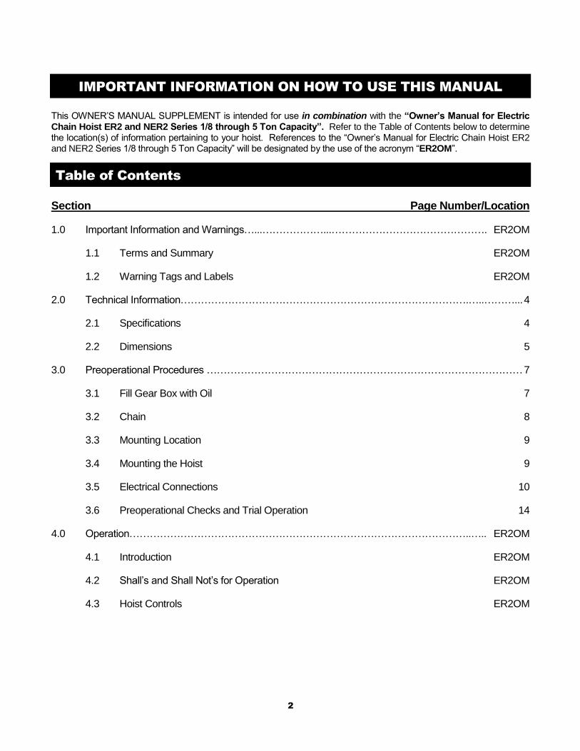
IMPORTANT INFORMATION ON HOW TO USE THIS MANUAL
This OWNER’S MANUAL SUPPLEMENT is intended for use in combination with the “Owner’s Manual for Electric Chain Hoist ER2 and NER2 Series 1/8 through 5 Ton Capacity”. Refer to the Table of Contents below to determine the location(s) of information pertaining to your hoist. References to the “Owner’s Manual for Electric Chain Hoist ER2 and NER2 Series 1/8 through 5 Ton Capacity” will be designated by the use of the acronym “ER2OM”.
Table of Contents
Section Page Number/Location
1.0 Important Information and Warnings…...………………...………………………………………. ER2OM
1.1 Terms and Summary ER2OM
1.2 Warning Tags and Labels ER2OM
2.0 Technical Information………………………………………………………………………….…..………... 4
2.1 Specifications 4
2.2 Dimensions 5
3.0 Preoperational Procedures ………………………………………………………………………………… 7
3.1 Fill Gear Box with Oil 7
3.2 Chain 8
3.3 Mounting Location 9
3.4 Mounting the Hoist 9
3.5 Electrical Connections 10
3.6 Preoperational Checks and Trial Operation 14
4.0 Operation………………………………………………………………………………………..….. ER2OM
4.1 Introduction ER2OM
4.2 Shall’s and Shall Not’s for Operation ER2OM
4.3 Hoist Controls ER2OM
3
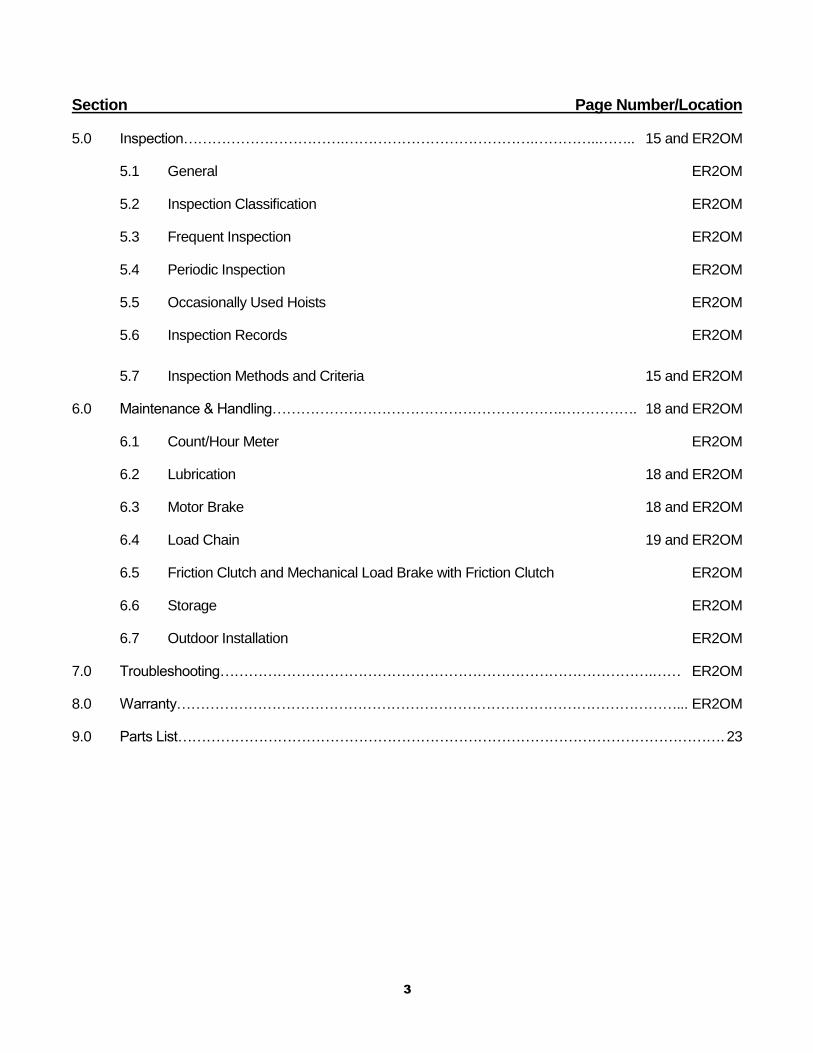
Section Page Number/Location
5.0 Inspection…………………………….………………………………….…………..…….. 15 and ER2OM
5.1 General ER2OM
5.2 Inspection Classification ER2OM
5.3 Frequent Inspection ER2OM
5.4 Periodic Inspection ER2OM
5.5 Occasionally Used Hoists ER2OM
5.6 Inspection Records ER2OM
5.7 Inspection Methods and Criteria 15 and ER2OM
6.0 Maintenance & Handling…………………………………………………….……………. 18 and ER2OM
6.1 Count/Hour Meter ER2OM
6.2 Lubrication 18 and ER2OM
6.3 Motor Brake 18 and ER2OM
6.4 Load Chain 19 and ER2OM
6.5 Friction Clutch and Mechanical Load Brake with Friction Clutch ER2OM
6.6 Storage ER2OM
6.7 Outdoor Installation ER2OM
7.0 Troubleshooting……………………………………………………………………………….…… ER2OM
8.0 Warranty……………………………………………………………………………………………... ER2OM
9.0 Parts List……………………………………………………………………………………………………. 23
4
2.0 Technical Information
2.1 Specifications
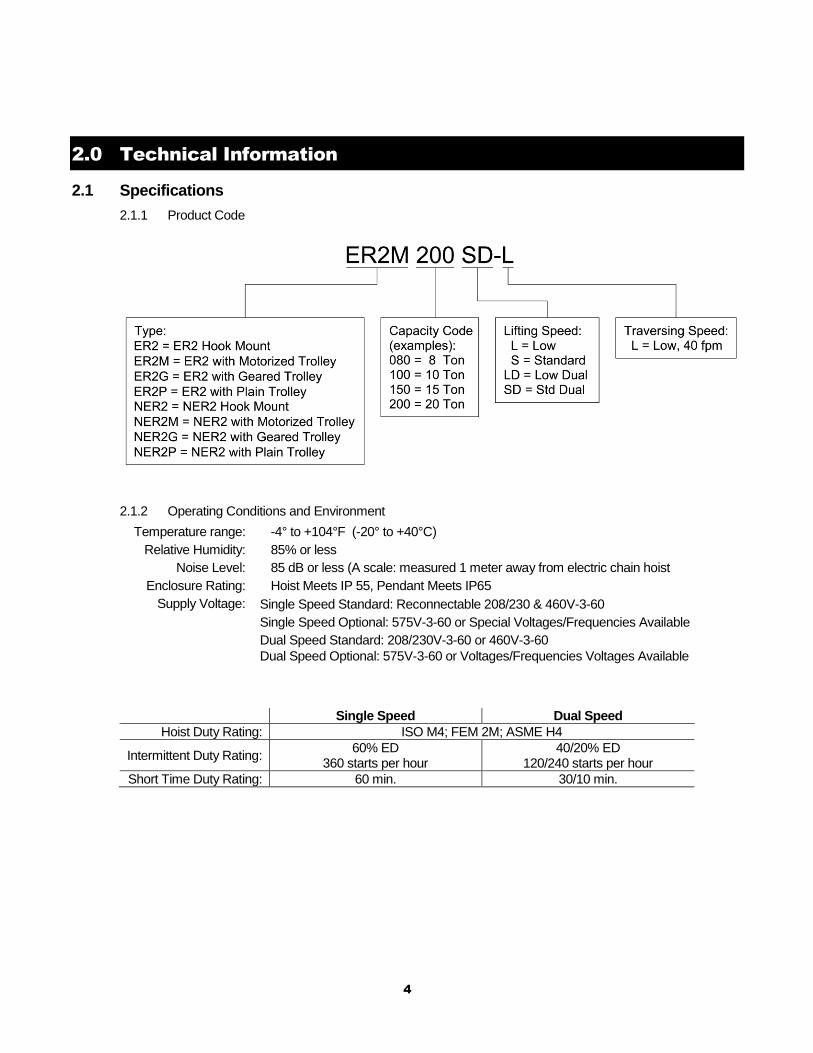
2.1.1 Product Code
2.1.2 Operating Conditions and Environment
Temperature range: -4° to +104°F (-20° to +40°C)
Relative Humidity: 85% or less
Noise Level: 85 dB or less (A scale: measured 1 meter away from electric chain hoist
Enclosure Rating: Hoist Meets IP 55, Pendant Meets IP65
Supply Voltage: Single Speed Standard: Reconnectable 208/230 & 460V-3-60
Single Speed Optional: 575V-3-60 or Special Voltages/Frequencies Available
Dual Speed Standard: 208/230V-3-60 or 460V-3-60
Dual Speed Optional: 575V-3-60 or Voltages/Frequencies Voltages Available
Single Speed Dual Speed
Hoist Duty Rating: ISO M4; FEM 2M; ASME H4
Intermittent Duty Rating: 60% ED
360 starts per hour 40/20% ED
120/240 starts per hour
Short Time Duty Rating: 60 min. 30/10 min.
5
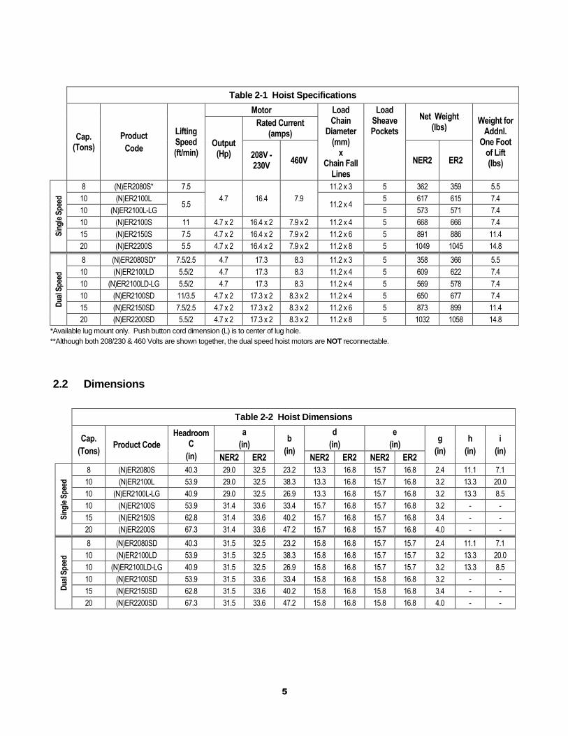
Table 2-1 Hoist Specifications
Cap. (Tons)
Product
Code
Lifting Speed (ft/min)
Motor Load Chain
Diameter (mm)
x Chain Fall
Lines
Load Sheave Pockets
Net Weight (lbs)
Weight for Addnl.
One Foot of Lift (lbs)
Output (Hp)
Rated Current (amps)
208V - 230V
460V NER2 ER2
Sin
gle
Sp
eed
8 (N)ER2080S* 7.5
4.7 16.4 7.9
11.2 x 3 5 362 359 5.5
10 (N)ER2100L 5.5 11.2 x 4
5 617 615 7.4
10 (N)ER2100L-LG 5 573 571 7.4
10 (N)ER2100S 11 4.7 x 2 16.4 x 2 7.9 x 2 11.2 x 4 5 668 666 7.4
15 (N)ER2150S 7.5 4.7 x 2 16.4 x 2 7.9 x 2 11.2 x 6 5 891 886 11.4
20 (N)ER2200S 5.5 4.7 x 2 16.4 x 2 7.9 x 2 11.2 x 8 5 1049 1045 14.8
Du
al S
pee
d
8 (N)ER2080SD* 7.5/2.5 4.7 17.3 8.3 11.2 x 3 5 358 366 5.5
10 (N)ER2100LD 5.5/2 4.7 17.3 8.3 11.2 x 4 5 609 622 7.4
10 (N)ER2100LD-LG 5.5/2 4.7 17.3 8.3 11.2 x 4 5 569 578 7.4
10 (N)ER2100SD 11/3.5 4.7 x 2 17.3 x 2 8.3 x 2 11.2 x 4 5 650 677 7.4
15 (N)ER2150SD 7.5/2.5 4.7 x 2 17.3 x 2 8.3 x 2 11.2 x 6 5 873 899 11.4
20 (N)ER2200SD 5.5/2 4.7 x 2 17.3 x 2 8.3 x 2 11.2 x 8 5 1032 1058 14.8
*Available lug mount only. Push button cord dimension (L) is to center of lug hole.
**Although both 208/230 & 460 Volts are shown together, the dual speed hoist motors are NOT reconnectable.
2.2 Dimensions
Table 2-2 Hoist Dimensions
Cap.
(Tons) Product Code
Headroom C
(in)
a
(in) b
(in)
d
(in)
e
(in) g
(in)
h
(in)
i
(in) NER2 ER2 NER2 ER2 NER2 ER2
Sin
gle
Sp
eed
8 (N)ER2080S 40.3 29.0 32.5 23.2 13.3 16.8 15.7 16.8 2.4 11.1 7.1
10 (N)ER2100L 53.9 29.0 32.5 38.3 13.3 16.8 15.7 16.8 3.2 13.3 20.0
10 (N)ER2100L-LG 40.9 29.0 32.5 26.9 13.3 16.8 15.7 16.8 3.2 13.3 8.5
10 (N)ER2100S 53.9 31.4 33.6 33.4 15.7 16.8 15.7 16.8 3.2 - -
15 (N)ER2150S 62.8 31.4 33.6 40.2 15.7 16.8 15.7 16.8 3.4 - -
20 (N)ER2200S 67.3 31.4 33.6 47.2 15.7 16.8 15.7 16.8 4.0 - -
Du
al S
pee
d
8 (N)ER2080SD 40.3 31.5 32.5 23.2 15.8 16.8 15.7 15.7 2.4 11.1 7.1
10 (N)ER2100LD 53.9 31.5 32.5 38.3 15.8 16.8 15.7 15.7 3.2 13.3 20.0
10 (N)ER2100LD-LG 40.9 31.5 32.5 26.9 15.8 16.8 15.7 15.7 3.2 13.3 8.5
10 (N)ER2100SD 53.9 31.5 33.6 33.4 15.8 16.8 15.8 16.8 3.2 - -
15 (N)ER2150SD 62.8 31.5 33.6 40.2 15.8 16.8 15.8 16.8 3.4 - -
20 (N)ER2200SD 67.3 31.5 33.6 47.2 15.8 16.8 15.8 16.8 4.0 - -
6
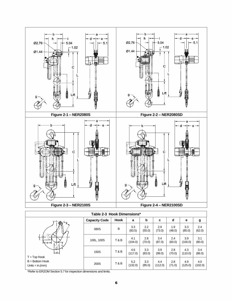
Figure 2-1 – NER2080S Figure 2-2 – NER2080SD
Figure 2-3 – NER2100S Figure 2-4 – NER2100SD
Table 2-3 Hook Dimensions*
T = Top Hook
B = Bottom Hook
Units = in.(mm)
Capacity Code Hook a b c d e g
080S B 3.3
(83.5) 2.2
(55.0) 2.9
(73.0) 1.9
(48.0) 3.3
(85.0) 2.4
(62.0)
100L, 100S T & B 4.1
(104.0) 2.8
(70.0) 3.4
(87.0) 2.4
(60.0) 3.9
(100.0) 3.1
(80.0)
150S T & B 4.6
(117.0) 3.3
(83.0) 3.9
(99.0) 2.8
(70.0) 4.3
(110.0) 3.4
(86.0)
200S T & B 5.2
(132.0) 3.3
(85.0) 4.4
(112.0) 2.8
(71.0) 4.9
(125.0) 4.0
(102.0)
*Refer to ER2OM Section 5.7 for inspection dimensions and limits.
7
3.0 Preoperational Procedures
3.1 Gear Box
3.1.1 The gearbox is filled with the correct amount of oil at the time of shipment. The oil level must be verified prior to operation. The ER2 and NER2 hoists have different checking procedures. Refer to Section 6.3 of the ER2OM for specific checking procedures. Use the 050L Capacity Code to determine the correct “Check Distance” for the ER2 Large Capacity hoist.
3.1.2 Refer to Section 6.3 of the ER2OM when replacing the gear oil. Use the 050L Capacity Code to determine the correct amount of gear oil.
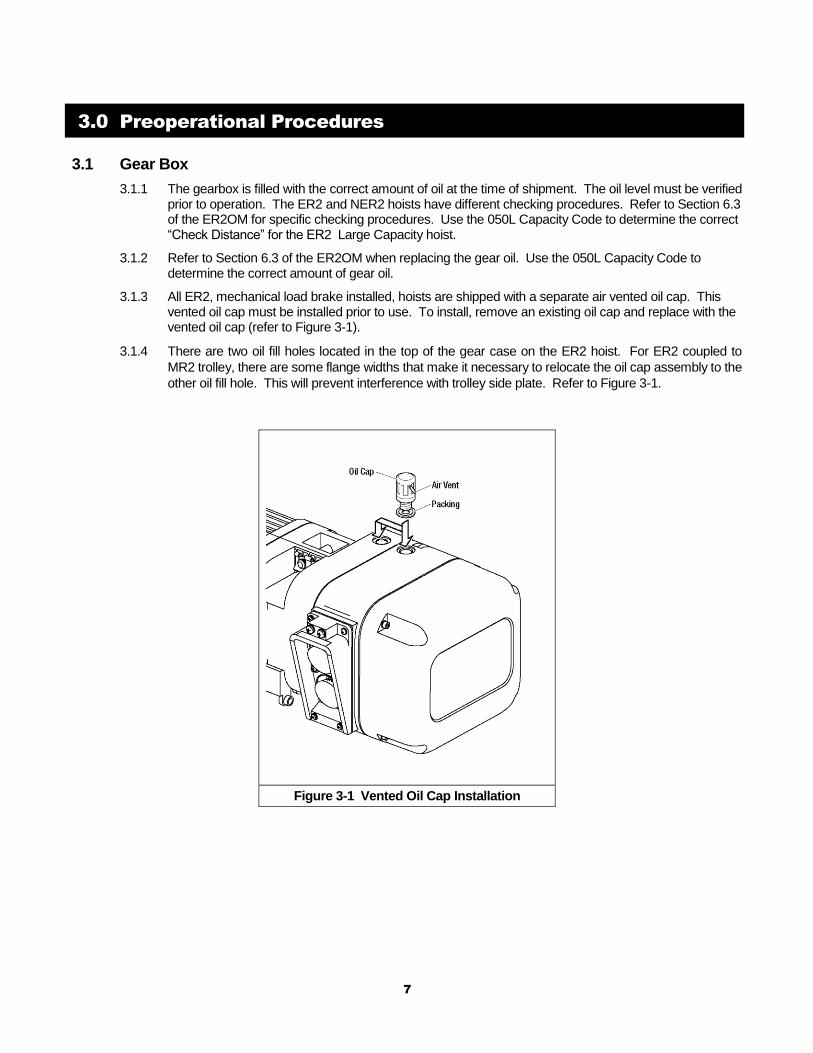
3.1.3 All ER2, mechanical load brake installed, hoists are shipped with a separate air vented oil cap. This vented oil cap must be installed prior to use. To install, remove an existing oil cap and replace with the vented oil cap (refer to Figure 3-1).
3.1.4 There are two oil fill holes located in the top of the gear case on the ER2 hoist. For ER2 coupled to
MR2 trolley, there are some flange widths that make it necessary to relocate the oil cap assembly to the
other oil fill hole. This will prevent interference with trolley side plate. Refer to Figure 3-1.
Figure 3-1 Vented Oil Cap Installation
8
3.2 Chain
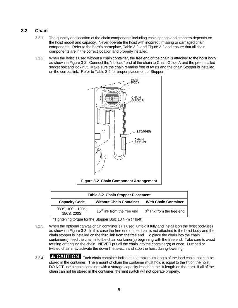
3.2.1 The quantity and location of the chain components including chain springs and stoppers depends on the hoist model and capacity. Never operate the hoist with incorrect, missing or damaged chain components. Refer to the hoist's nameplate, Table 3-2, and Figure 3-2 and ensure that all chain components are in the correct location and properly installed.
3.2.2 When the hoist is used without a chain container, the free end of the chain is attached to the hoist body as shown in Figure 3-2. Connect the “no load” end of the chain to Chain Guide A and the pre-installed socket bolt and lock nut. Make sure the chain remains free of twists and the chain Stopper is installed on the correct link. Refer to Table 3-2 for proper placement of Stopper.
Figure 3-2 Chain Component Arrangement
Table 3-2 Chain Stopper Placement
Capacity Code Without Chain Container With Chain Container
080S, 100L, 100S, 150S, 200S
15th link from the free end 3
rd link from the free end
*Tightening torque for the Stopper Bolt: 10 N-m (7 lb-ft)
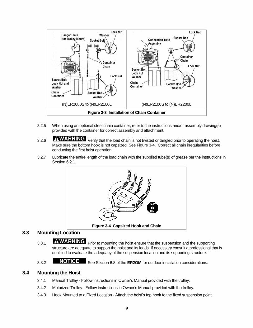
3.2.3 When the optional canvas chain container(s) is used, unfold it fully and install it on the hoist body(ies) as shown in Figure 3-3. In this case the free end of the chain is not attached to the hoist body and the chain stopper is installed on the third link from the free end. To place the chain into the chain container(s), feed the chain into the chain container(s) beginning with the free end. Take care to avoid twisting or tangling the chain. NEVER put all the chain into the container(s) at once. Lumped or twisted chain may activate the down limit switch and stop the hoist during lowering.
3.2.4 Each chain container indicates the maximum length of the load chain that can be stored in the container. The amount of chain the container must hold is equal to the lift on the hoist. DO NOT use a chain container with a storage capacity less than the lift length on the hoist. If all of the chain can not be stored in the container, the limit switch will not operate properly.
9
(N)ER2080S to (N)ER2100L
(N)ER2100S to (N)ER2200L
Figure 3-3 Installation of Chain Container
3.2.5 When using an optional steel chain container, refer to the instructions and/or assembly drawing(s) provided with the container for correct assembly and attachment.
3.2.6 Verify that the load chain is not twisted or tangled prior to operating the hoist. Make sure the bottom hook is not capsized. See Figure 3-4. Correct all chain irregularities before conducting the first hoist operation.
3.2.7 Lubricate the entire length of the load chain with the supplied tube(s) of grease per the instructions in Section 6.2.1.
Figure 3-4 Capsized Hook and Chain
3.3 Mounting Location
3.3.1 Prior to mounting the hoist ensure that the suspension and the supporting structure are adequate to support the hoist and its loads. If necessary consult a professional that is qualified to evaluate the adequacy of the suspension location and its supporting structure.
3.3.2 See Section 6.8 of the ER2OM for outdoor installation considerations.
3.4 Mounting the Hoist
3.4.1 Manual Trolley - Follow instructions in Owner’s Manual provided with the trolley.
3.4.2 Motorized Trolley - Follow instructions in Owner’s Manual provided with the trolley.
3.4.3 Hook Mounted to a Fixed Location - Attach the hoist’s top hook to the fixed suspension point.
10
3.4.4 Lug Mounted ER2080S and ER2100L-LG – To maintain proper balance when the hoist is not loaded, it is necessary to install a stabilizing shaft to prevent the hoist from pivoting on the main support shaft. Refer to Figure 2-1 and Figure 2-2 for the size and location of the main support and stablizing holes in the hoist’s top suspension plates.
3.4.5 Ensure that the fixed suspension point rests on the center of the hook’s saddle and that the hook’s latch is engaged.
3.5 Electrical Connections
3.5.1 Ensure that the voltage of the electric power supply is proper for the hoist or trolley.
3.5.2 Do NOT apply electronic soft-start control or voltage varying controls to the ER2 or NER2 hoist. Use of such devices may cause the motor brake and other electrical components to malfunction. Variable frequency drives MAY be used with the single speed ER2/NER2 hoists, contact Harrington Hoists, Inc. for more information.
3.5.3 Before proceeding, ensure that the electrical supply for the hoist or trolley has been de-energized (disconnected). Lock out and tag out in accordance with ANSI Z244.1 “Personnel Protection -Lockout/Tagout of Energy Sources”.
3.5.4 To avoid a shock hazard, DO NOT perform ANY mechanical or electrical maintenance on the dual speed ( VFD control) trolley or hoist within 5 minutes of de-energizing (disconnecting) the trolley or hoist. This time allows the internal VFD capacitor to safely discharge.
3.5.5 Do NOT remove power to the dual speed (VFD control) hoist or trolley during operation.
3.5.6 All dual speed hoists are equiped with a VFD. The VFD is used to control the high and low lifting speeds. The speeds come preset from the factory (See Table 3-6, ER2OM). Speed (frequency) can be customized. Refer to Section 3.6.10 of ER2OM, for hoist specific speed ranges and instructions.
3.5.7 The following instructions apply when the hoist is hook mounted to a fixed suspension point or installed on a manual trolley. The hoist is controlled by a pendant with two push buttons – one for lifting and one for lowering. Refer to the appropriate trolley Owner’s Manual if the hoist is installed on a motorized trolley. Special wiring considerations must be taken if the trolley is used with a trolley other than an MR2 model.
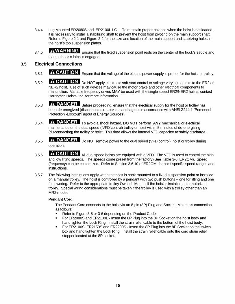
Pendant Cord
The Pendant Cord connects to the hoist via an 8-pin (8P) Plug and Socket. Make this connection as follows: Refer to Figure 3-5 or 3-6 depending on the Product Code. For ER2080S and ER2100L - Insert the 8P Plug into the 8P Socket on the hoist body and
hand tighten the Lock Ring. Install the strain relief cable to the bottom of the hoist body. For ER2100S, ER2150S and ER2200S - Insert the 8P Plug into the 8P Socket on the switch
box and hand tighten the Lock Ring. Install the strain relief cable onto the cord strain relief stopper located at the 8P socket.
11
Power Supply Cable - Hoist Connection
The Power Supply Cable connects to the hoist via a 4-pin (4P) plug and socket or a direct fitting depending on the product code. Make this connection as follows: Refer to Figure 3-5 or 3-6 depending on the product code. For ER2080S and ER2100L insert the 4P plug of the Power Supply Cable into the 4P Socket
on the hoist and hand tighten the Lock Ring. For ER2100S, ER2150S, and ER2200S – The power supply cable should be pre-installed to
the switch box and properly connected. Install the Cable Support Arm (pre-installed on the Power Supply Cable) on to the Socket
Holder or Switch Box depending on the product code. Use the pre-installed Machine Screws and Lock Washers.
Use care to avoid twisting or kinking the Power Supply Cable. Insert the 4P Plug into the 4P Socket on the hoist and hand-tighten the Lock Ring.
Figure 3-5 Pendant and Power Supply Cable Connections for ER2080S and ER2100L
12
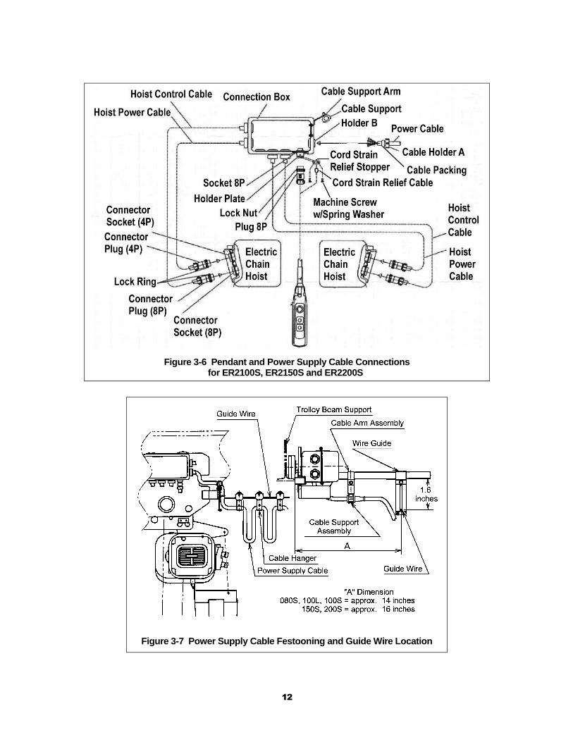
Figure 3-6 Pendant and Power Supply Cable Connections for ER2100S, ER2150S and ER2200S
Figure 3-7 Power Supply Cable Festooning and Guide Wire Location
13
Power Supply Cable - Installation
If the hoist is hook mounted to a fixed support ensure that the Power Supply Cable is properly installed and supported between the hoist and the electrical power supply. If the hoist is installed on a manual trolley, then the Power Supply Cable must be installed along the beam that the trolley runs on. For curved beams a special cable suspension system will be needed, and this instruction does not apply. For straight beams install the Power Supply Cable as follows: Refer to Figure 3-7. Install the Cable Hangers on to the Power Supply Cable spacing them every 5 feet. Install a Guide Wire system parallel to the Bridge Beam. Pass the Guide Wire through the
Cable Hangers and the Wire Guide. Make sure the Guide Wire is properly tensioned and the Power Supply Cable is not twisted or
kinked.
3.5.8 Connection to Electrical Power Source - The red, blue, and black wires of the Power Supply Cable should be connected to an Electric Power Disconnect Switch or Circuit Breaker. This connection should be made so that the hoist is phased properly. Refer to Section 3.6.11 for instructions on how to check for correct power supply phase connection.
3.5.9 Fuse/Breaker Capacity -The hoist's power supply should be equipped with overcurrent protection such as fuses, which should be selected for 110% to 120% of total listed full load amperage, and should be dual element time-delay fuses. Refer to the motor nameplate(s) for the full load amperage draw.
3.5.10 Grounding - An improper or insufficient ground connection creates an electrical shock hazard when touching any part of the hoist or trolley. In the Power Supply Cable the ground wire will be either Green with Yellow stripe or solid Green. It should always be connected to a suitable ground connection. Do not paint the trolley wheel running surfaces of the beam as this can affect grounding.
14
3.6 Preoperational Checks and Trial Operation
3.6.1 Refer to the hoist’s nameplate and record the hoist's Code, Lot and Serial Number in the space provided on the cover of this manual.
3.6.2 Confirm the adequacy of the rated capacity for all slings, chains, wire ropes and all other lifting attachments before use. Inspect all load suspension members for damage prior to use and replace or repair all damaged parts.
3.6.3 Verify and correct all chain irregularities prior to operating the hoist. Refer to Section 3.2 of this manual.
3.6.4 Measure and record the “k” dimension of all hooks on hoist. See Table 5-4 under Section 5 “Inspection”, of this manual.
3.6.5 Ensure that the hoist is properly installed to either a fixed point, or trolley, whichever applies.
3.6.6 If hoist is installed on a trolley, ensure that
trolley is properly installed on the beam, and stops for the trolley are correctly positioned and securely installed on the beam.
3.6.7 Ensure that all nuts, bolts and split pins (cotter pins) are sufficiently fastened.
3.6.8 Pull down on the Pendant and ensure that the Cord Strain Relief Cable takes the force, not the Pendant Cord.
3.6.9 Check supply voltage before everyday use. If the voltage varies more than 10% of the rated value, electrical devices may not function normally.
3.6.10 Confirm proper operation.
Before operating read and become familiar with Section 4 – Operation in the ER2OM.
Before operating ensure that the hoist (and trolley) meets the Inspection, Testing and Maintenance requirements of ANSI/ASME B30.16.
Before operating ensure that nothing will interfere with the full range of the hoist’s (and trolley’s) operation.
3.6.11 Proceed with trial operation to confirm proper operation.
Verify that the controls agree with hoist direction. Make sure that depression of the up button lifts the load chain and depression of the down button lowers the load chain hook. If the load chain does not move in the correct direction when the push buttons are pushed, the power supply is phased incorrectly. In this case, turn off the power source or breaker switch then reverse any two of the three wires at the power source. The hook will then move in accordance with the directions of the push button.
Perform inspections per Section 5.2, “Frequent Inspections” in the ER2OM.
15
5.0 Inspection
The information listed in this section is intended to supplement Section 5.7 of the ER2OM.
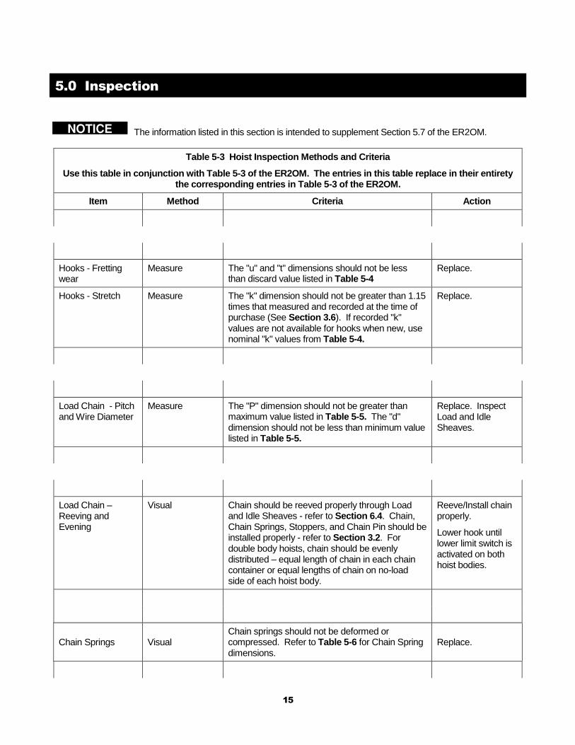
Table 5-3 Hoist Inspection Methods and Criteria
Use this table in conjunction with Table 5-3 of the ER2OM. The entries in this table replace in their entirety the corresponding entries in Table 5-3 of the ER2OM.
Item Method Criteria Action
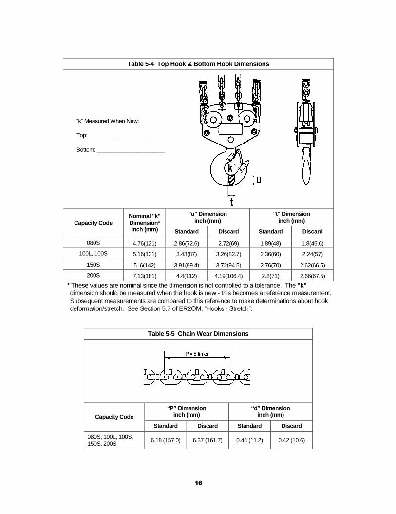
Hooks - Fretting wear
Measure The "u" and "t" dimensions should not be less than discard value listed in Table 5-4
Replace.
Hooks - Stretch Measure The "k" dimension should not be greater than 1.15 times that measured and recorded at the time of purchase (See Section 3.6). If recorded "k" values are not available for hooks when new, use nominal "k" values from Table 5-4.
Replace.
Load Chain - Pitch and Wire Diameter
Measure The "P" dimension should not be greater than maximum value listed in Table 5-5. The "d" dimension should not be less than minimum value listed in Table 5-5.
Replace. Inspect Load and Idle Sheaves.
Load Chain – Reeving and Evening
Visual Chain should be reeved properly through Load and Idle Sheaves - refer to Section 6.4. Chain, Chain Springs, Stoppers, and Chain Pin should be installed properly - refer to Section 3.2. For double body hoists, chain should be evenly distributed – equal length of chain in each chain container or equal lengths of chain on no-load side of each hoist body.
Reeve/Install chain properly.
Lower hook until lower limit switch is activated on both hoist bodies.
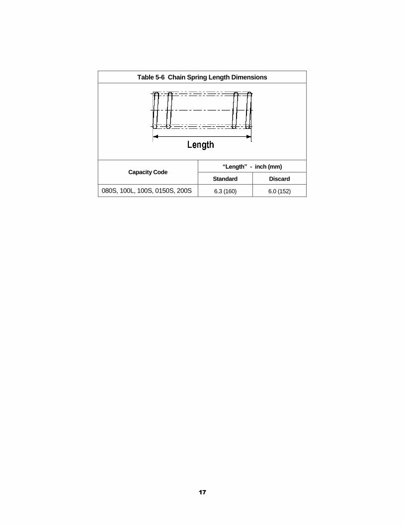
Chain Springs Visual Chain springs should not be deformed or compressed. Refer to Table 5-6 for Chain Spring dimensions.
Replace.
16
Table 5-4 Top Hook & Bottom Hook Dimensions
“k” Measured When New:
Top: _________________________
Bottom: ______________________
Capacity Code Nominal "k" Dimension* inch (mm)
"u" Dimension inch (mm)
"t" Dimension inch (mm)
Standard Discard Standard Discard
080S 4.76(121) 2.86(72.6) 2.72(69) 1.89(48) 1.8(45.6)
100L, 100S 5.16(131) 3.43(87) 3.26(82.7) 2.36(60) 2.24(57)
150S 5..6(142) 3.91(99.4) 3.72(94.5) 2.76(70) 2.62(66.5)
200S 7.13(181) 4.4(112) 4.19(106.4) 2.8(71) 2.66(67.5)
* These values are nominal since the dimension is not controlled to a tolerance. The "k"
dimension should be measured when the hook is new - this becomes a reference measurement.
Subsequent measurements are compared to this reference to make determinations about hook
deformation/stretch. See Section 5.7 of ER2OM, “Hooks - Stretch”.
Table 5-5 Chain Wear Dimensions
Capacity Code
“P” Dimension inch (mm)
“d” Dimension inch (mm)
Standard Discard Standard Discard
080S, 100L, 100S, 150S, 200S
6.18 (157.0) 6.37 (161.7) 0.44 (11.2) 0.42 (10.6)
17
Table 5-6 Chain Spring Length Dimensions
Capacity Code “Length” - inch (mm)
Standard Discard
080S, 100L, 100S, 0150S, 200S 6.3 (160) 6.0 (152)
18
6.0 Maintenance and Handling
6.2 Lubrication
6.2.1 Load Chain
Refer to 6.2.1 of the ER2OM.
6.2.2 Hooks and Suspension Components:
Refer to 6.2.2 of the ER2OM.
6.2.3 Gear Box:
Refer to 6.3 of the ER2OM except use the following table for checking oil level.
Table 6-1 ER2 (Mechanical Load brake Equipped) Gear Oil Check Distances
Capacity Code Check Distance
(inches) Check Distance
(millimeters)
080S, 100L, 100S, 0150S, 200S 5.12 130
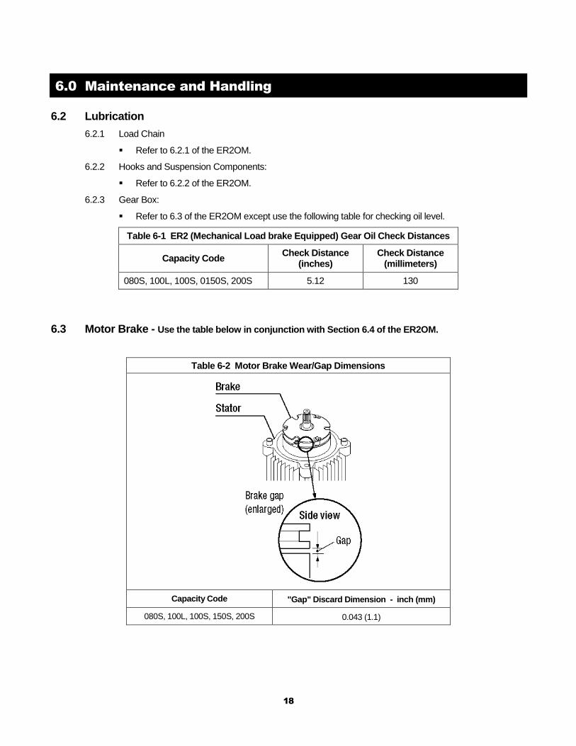
6.3 Motor Brake - Use the table below in conjunction with Section 6.4 of the ER2OM.
Table 6-2 Motor Brake Wear/Gap Dimensions
Capacity Code "Gap" Discard Dimension - inch (mm)
080S, 100L, 100S, 150S, 200S 0.043 (1.1)
19
6.4 Load Chain
6.4.1 Lubrication and Cleaning – refer to Section 6.2 of ER2OM.
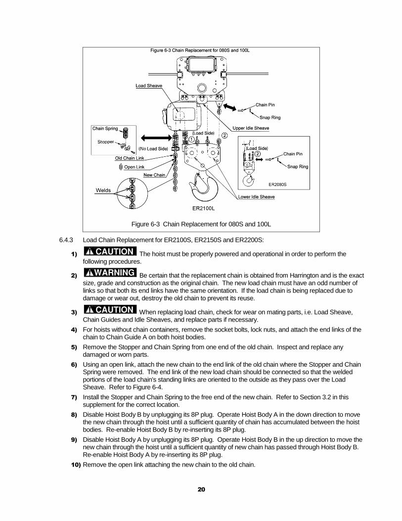
6.4.2 Load Chain Replacement for ER2080S and ER2100L:
1) The hoist must be properly powered and operational in order to perform the
following procedures.
2) Be certain that the replacement chain is obtained from Harrington and is the exact
size, grade and construction as the original chain. The new load chain must have an odd number of
links so that both its end links have the same orientation. If the load chain is being replaced due to
damage or wear out, destroy the old chain to prevent its reuse.
3) When replacing load chain, check for wear on mating parts, i.e. Load Sheave,
Chain Guides and Idle Sheaves, and replace parts if necessary.
4) For hoists without a chain container, remove the socket bolt, lock nut, and attach the no-load side of the
chain to Chain Guide A.
5) Remove the Stopper and Chain Spring from the no-load side of the chain for reuse on the new chain.
Inspect and replace any damaged or worn parts.
6) Using an open link, attach the new chain to the end link of the old chain on the no-load side. The end
link of the new load chain should be connected so that the welded portions of the load chain's standing
links are oriented to the outside as they pass over the Load Sheave. Refer to Figure 6-3.
7) Operate the hoist down to move the new chain though the hoist body. Stop when a sufficient amount
of new chain is accumulated on the load side.
8) Complete reeving as follows:
For ER2080S pull down on Part until new chain is fed through the upper and lower idle sheaves. Secure the new chain at Part directly below the upper suspension plates to prevent the new chain from running back through the idle sheaves. Remove the open link attaching the new chain to the old chain.
For ER2100L pull up on Part until the new chain is fed through the upper and lower idle sheaves. Secure the new chain at Part directly above the lower idle sheave to prevent the new chain from running back through the idle sheaves. Remove the open link attaching the new chain to the old chain.
9) Remove the Snap Ring and Chain Pin that attach the old chain to the chain holder for use on the new
chain. Inspect and replace any damaged or worn parts.
10) Connect the end link of the new chain to the chain holder with the Chain Pin and Snap Ring. Ensure
that the chain remains free of twists. Attach the remaining chain components to the chain referring to
Section 3.2 for the proper locations. For hoists without a chain container, attach the no-load side of the
chain to Chain Guide A with the socket bolt, and lock nut. See Figure 3-2.
11) Make sure the Stopper and Chain Springs are properly installed. Refer to Section
3.2.
12) After installation has been completed, perform steps outlined in Section 3.6 "Preoperational Checks
and Trial Operation".
20
Figure 6-3 Chain Replacement for 080S and 100L
6.4.3 Load Chain Replacement for ER2100S, ER2150S and ER2200S:
1) The hoist must be properly powered and operational in order to perform the following procedures.
2) Be certain that the replacement chain is obtained from Harrington and is the exact size, grade and construction as the original chain. The new load chain must have an odd number of links so that both its end links have the same orientation. If the load chain is being replaced due to damage or wear out, destroy the old chain to prevent its reuse.
3) When replacing load chain, check for wear on mating parts, i.e. Load Sheave, Chain Guides and Idle Sheaves, and replace parts if necessary.
4) For hoists without chain containers, remove the socket bolts, lock nuts, and attach the end links of the chain to Chain Guide A on both hoist bodies.
5) Remove the Stopper and Chain Spring from one end of the old chain. Inspect and replace any damaged or worn parts.
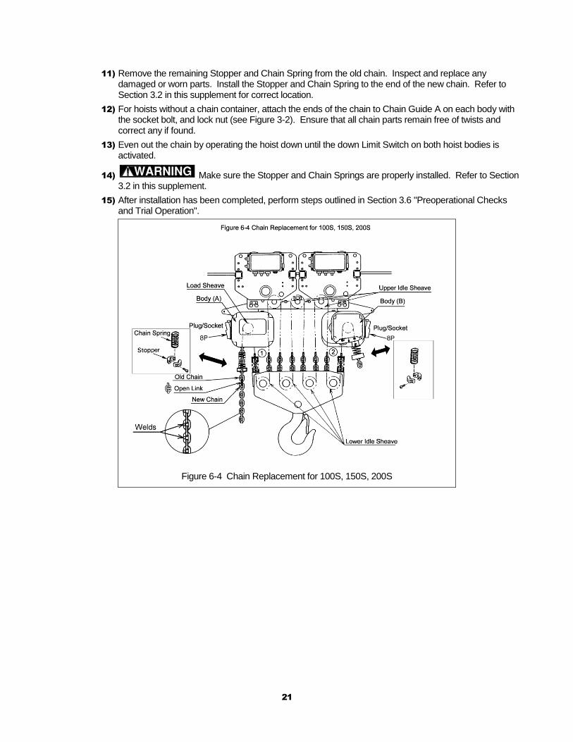
6) Using an open link, attach the new chain to the end link of the old chain where the Stopper and Chain Spring were removed. The end link of the new load chain should be connected so that the welded portions of the load chain's standing links are oriented to the outside as they pass over the Load Sheave. Refer to Figure 6-4.
7) Install the Stopper and Chain Spring to the free end of the new chain. Refer to Section 3.2 in this supplement for the correct location.
8) Disable Hoist Body B by unplugging its 8P plug. Operate Hoist Body A in the down direction to move the new chain through the hoist until a sufficient quantity of chain has accumulated between the hoist bodies. Re-enable Hoist Body B by re-inserting its 8P plug.
9) Disable Hoist Body A by unplugging its 8P plug. Operate Hoist Body B in the up direction to move the new chain through the hoist until a sufficient quantity of new chain has passed through Hoist Body B. Re-enable Hoist Body A by re-inserting its 8P plug.
10) Remove the open link attaching the new chain to the old chain.
21
11) Remove the remaining Stopper and Chain Spring from the old chain. Inspect and replace any damaged or worn parts. Install the Stopper and Chain Spring to the end of the new chain. Refer to Section 3.2 in this supplement for correct location.
12) For hoists without a chain container, attach the ends of the chain to Chain Guide A on each body with the socket bolt, and lock nut (see Figure 3-2). Ensure that all chain parts remain free of twists and correct any if found.
13) Even out the chain by operating the hoist down until the down Limit Switch on both hoist bodies is activated.
14) Make sure the Stopper and Chain Springs are properly installed. Refer to Section 3.2 in this supplement.
15) After installation has been completed, perform steps outlined in Section 3.6 "Preoperational Checks and Trial Operation".
Figure 6-4 Chain Replacement for 100S, 150S, 200S
22
This Page Intentionally Left Blank
10.3 H
ook P
arts
23
9.0 Parts List
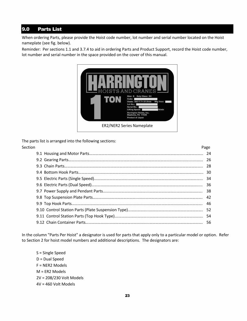
When ordering Parts, please provide the Hoist code number, lot number and serial number located on the Hoist nameplate (see fig. below).
Reminder: Per sections 1.1 and 3.7.4 to aid in ordering Parts and Product Support, record the Hoist code number, lot number and serial number in the space provided on the cover of this manual.
ER2/NER2 Series Nameplate
The parts list is arranged into the following sections:
Section Page
9.1 Housing and Motor Parts……………………………………………….……………………………………………….. 24
9.2 Gearing Parts…………………………………………………………………………………………........................... 26
9.3 Chain Parts………………………………………………………………….………………………………………………….. 28
9.4 Bottom Hook Parts………………………………………………………………………………………………………….. 30
9.5 Electric Parts (Single Speed)…………………………………………………………….……………………………... 34
9.6 Electric Parts (Dual Speed)…………………………………………………………….……………………………..... 36
9.7 Power Supply and Pendant Parts……………………………………...……………………………………………. 38
9.8 Top Suspension Plate Parts……………………………………...……………….……………………………………. 42
9.9 Top Hook Parts……………………………………...............................……………………………………………. 46
9.10 Control Station Parts (Plate Suspension Type)………………...……………………………………………. 52
9.11 Control Station Parts (Top Hook Type).…………………………...……………………………………………. 54
9.12 Chain Container Parts………………..…………………………………...……………………………………………. 56
In the column "Parts Per Hoist" a designator is used for parts that apply only to a particular model or option. Refer to Section 2 for hoist model numbers and additional descriptions. The designators are:
S = Single Speed
D = Dual Speed
F = NER2 Models
M = ER2 Models
2V = 208/230 Volt Models
4V = 460 Volt Models
24
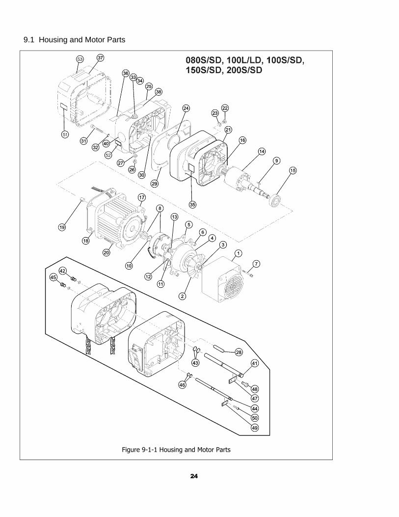
9.1 Housing and Motor Parts
Figure 9-1-1 Housing and Motor Parts
25
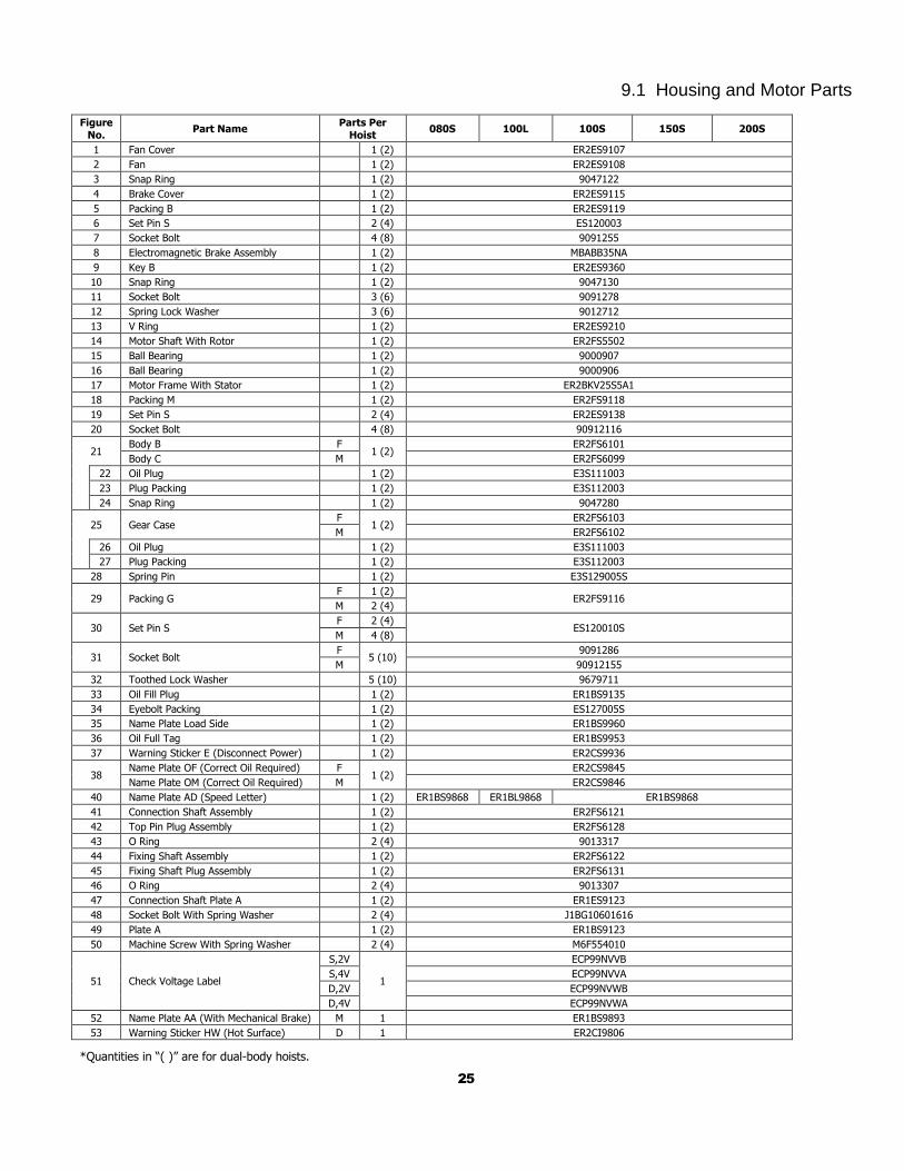
9.1 Housing and Motor Parts
Figure No.
Part Name Parts Per
Hoist 080S 100L 100S 150S 200S
1 Fan Cover 1 (2) ER2ES9107
2 Fan 1 (2) ER2ES9108
3 Snap Ring 1 (2) 9047122
4 Brake Cover 1 (2) ER2ES9115
5 Packing B 1 (2) ER2ES9119
6 Set Pin S 2 (4) ES120003
7 Socket Bolt 4 (8) 9091255
8 Electromagnetic Brake Assembly 1 (2) MBABB35NA
9 Key B 1 (2) ER2ES9360
10 Snap Ring 1 (2) 9047130
11 Socket Bolt 3 (6) 9091278
12 Spring Lock Washer 3 (6) 9012712
13 V Ring 1 (2) ER2ES9210
14 Motor Shaft With Rotor 1 (2) ER2FS5502
15 Ball Bearing 1 (2) 9000907
16 Ball Bearing 1 (2) 9000906
17 Motor Frame With Stator 1 (2) ER2BKV25S5A1
18 Packing M 1 (2) ER2FS9118
19 Set Pin S 2 (4) ER2ES9138
20 Socket Bolt 4 (8) 90912116
21 Body B F
1 (2) ER2FS6101
Body C M ER2FS6099
22 Oil Plug 1 (2) E3S111003
23 Plug Packing 1 (2) E3S112003
24 Snap Ring 1 (2) 9047280
25 Gear Case F
1 (2) ER2FS6103
M ER2FS6102
26 Oil Plug 1 (2) E3S111003
27 Plug Packing 1 (2) E3S112003
28 Spring Pin 1 (2) E3S129005S
29 Packing G F 1 (2)
ER2FS9116 M 2 (4)
30 Set Pin S F 2 (4)
ES120010S M 4 (8)
31 Socket Bolt F
5 (10) 9091286
M 90912155
32 Toothed Lock Washer 5 (10) 9679711
33 Oil Fill Plug 1 (2) ER1BS9135
34 Eyebolt Packing 1 (2) ES127005S
35 Name Plate Load Side 1 (2) ER1BS9960
36 Oil Full Tag 1 (2) ER1BS9953
37 Warning Sticker E (Disconnect Power) 1 (2) ER2CS9936
38 Name Plate OF (Correct Oil Required) F
1 (2) ER2CS9845
Name Plate OM (Correct Oil Required) M ER2CS9846
40 Name Plate AD (Speed Letter) 1 (2) ER1BS9868 ER1BL9868 ER1BS9868
41 Connection Shaft Assembly 1 (2) ER2FS6121
42 Top Pin Plug Assembly 1 (2) ER2FS6128
43 O Ring 2 (4) 9013317
44 Fixing Shaft Assembly 1 (2) ER2FS6122
45 Fixing Shaft Plug Assembly 1 (2) ER2FS6131
46 O Ring 2 (4) 9013307
47 Connection Shaft Plate A 1 (2) ER1ES9123
48 Socket Bolt With Spring Washer 2 (4) J1BG10601616
49 Plate A 1 (2) ER1BS9123
50 Machine Screw With Spring Washer 2 (4) M6F554010
51 Check Voltage Label
S,2V
1
ECP99NVVB
S,4V ECP99NVVA
D,2V ECP99NVWB
D,4V ECP99NVWA
52 Name Plate AA (With Mechanical Brake) M 1 ER1BS9893
53 Warning Sticker HW (Hot Surface) D 1 ER2CI9806
*Quantities in “( )” are for dual-body hoists.
26
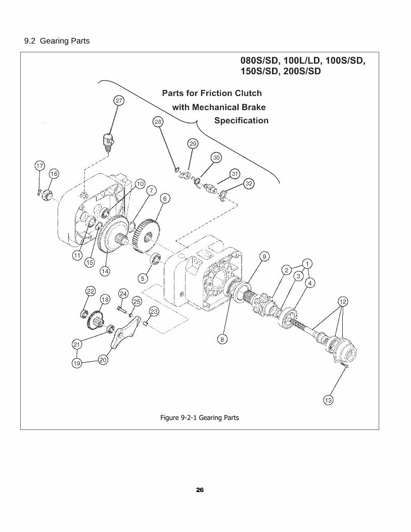
9.2 Gearing Parts
Figure 9-2-1 Gearing Parts
27
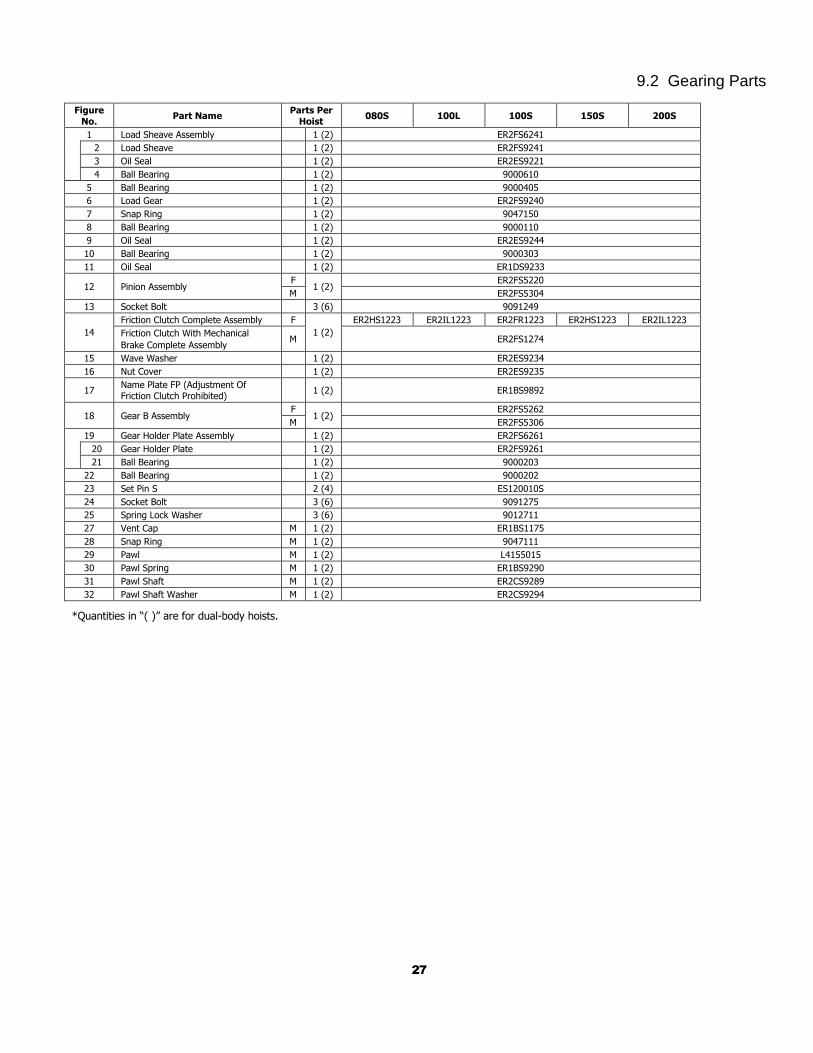
9.2 Gearing Parts
Figure No.
Part Name Parts Per
Hoist 080S 100L 100S 150S 200S
1 Load Sheave Assembly 1 (2) ER2FS6241
2 Load Sheave 1 (2) ER2FS9241
3 Oil Seal 1 (2) ER2ES9221
4 Ball Bearing 1 (2) 9000610
5 Ball Bearing 1 (2) 9000405
6 Load Gear 1 (2) ER2FS9240
7 Snap Ring 1 (2) 9047150
8 Ball Bearing 1 (2) 9000110
9 Oil Seal 1 (2) ER2ES9244
10 Ball Bearing 1 (2) 9000303
11 Oil Seal 1 (2) ER1DS9233
12 Pinion Assembly F
1 (2) ER2FS5220
M ER2FS5304
13 Socket Bolt 3 (6) 9091249
14
Friction Clutch Complete Assembly F
1 (2)
ER2HS1223 ER2IL1223 ER2FR1223 ER2HS1223 ER2IL1223
Friction Clutch With Mechanical
Brake Complete Assembly M ER2FS1274
15 Wave Washer 1 (2) ER2ES9234
16 Nut Cover 1 (2) ER2ES9235
17 Name Plate FP (Adjustment Of Friction Clutch Prohibited)
1 (2) ER1BS9892
18 Gear B Assembly F
1 (2) ER2FS5262
M ER2FS5306
19 Gear Holder Plate Assembly 1 (2) ER2FS6261
20 Gear Holder Plate 1 (2) ER2FS9261
21 Ball Bearing 1 (2) 9000203
22 Ball Bearing 1 (2) 9000202
23 Set Pin S 2 (4) ES120010S
24 Socket Bolt 3 (6) 9091275
25 Spring Lock Washer 3 (6) 9012711
27 Vent Cap M 1 (2) ER1BS1175
28 Snap Ring M 1 (2) 9047111
29 Pawl M 1 (2) L4155015
30 Pawl Spring M 1 (2) ER1BS9290
31 Pawl Shaft M 1 (2) ER2CS9289
32 Pawl Shaft Washer M 1 (2) ER2CS9294
*Quantities in “( )” are for dual-body hoists.
28
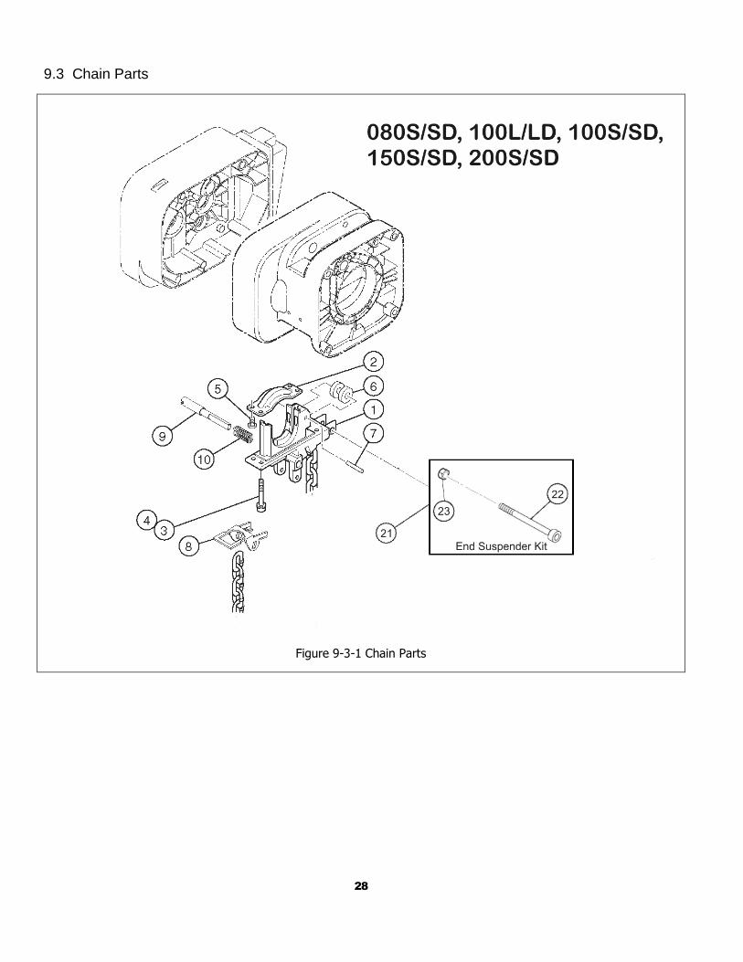
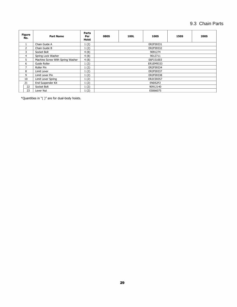
9.3 Chain Parts
Figure 9-3-1 Chain Parts
29
9.3 Chain Parts
*Quantities in “( )” are for dual-body hoists.
Figure No.
Part Name Parts Per
Hoist
080S 100L 100S 150S 200S
1 Chain Guide A 1 (2) ER2FS9331
2 Chain Guide B 1 (2) ER2FS9332
3 Socket Bolt 4 (8) 9091274
4 Spring Lock Washer 4 (8) 9012711
5 Machine Screw With Spring Washer 4 (8) E6F151003
6 Guide Roller 1 (2) ER1EM9333
7 Roller Pin 1 (2) ER2FS9334
8 Limit Lever 1 (2) ER2FS9337
9 Limit Lever Pin 1 (2) ER2FS9338
10 Limit Lever Spring 1 (2) ER2CS9357
21 End Suspender Kit 1 (2) ENDS2F2
22 Socket Bolt 1 (2) 90912140
23 Lever Nut 1 (2) ES066075
30
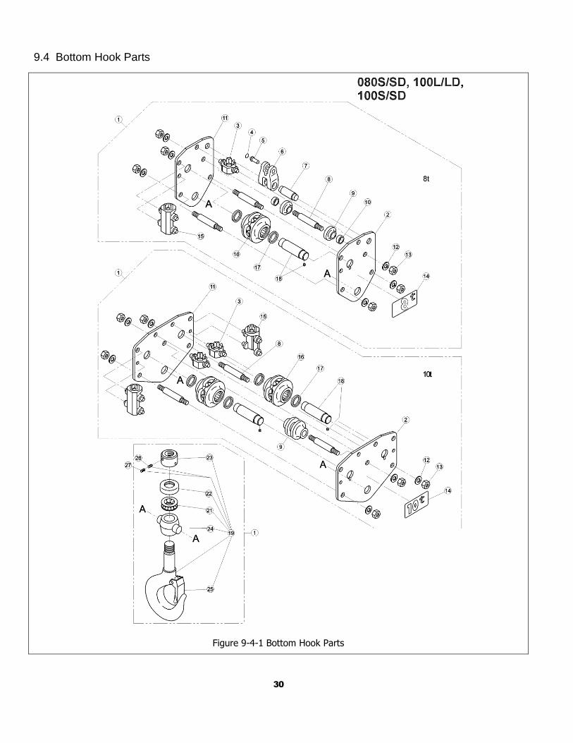
9.4 Bottom Hook Parts
Figure 9-4-1 Bottom Hook Parts
31
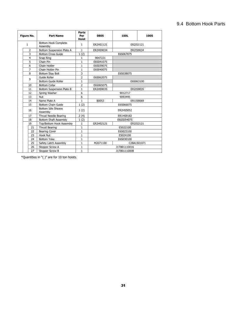
9.4 Bottom Hook Parts
Figure No. Part Name Parts Per
Hoist
080S 100L 100S
1 Bottom Hook Complete
Assembly 1 ER2HS1121 ER2IS1121
2 Bottom Suspension Plate A 1 ER2HS9034 ER2IS9034
3 Bottom Cross Guide 1 (2) E6S067075
4 Snap Ring 1 9047221
5 Chain Pin 1 E6S041075
6 Chain Holder 1 E6S039075
7 Chain Holder Pin 1 E6S040075
8 Bottom Stay Bolt 3 E6S038075
9 Guide Roller 2 E6S062075
Bottom Guide Roller 1 E6S063100
10 Bottom Collar 2 E6S065075
11 Bottom Suspension Plate B 1 ER2HS9035 ER2IS9035
12 Spring Washer 6 9012717
13 Nut 6 9093445
14 Name Plate A 1 80053 ER1IS9069
15 Bottom Chain Guide 1 (2) E6S066075
16 Bottom Idle Sheave
Assembly 1 (2) ER2HS5052
17 Thrust Needle Bearing 2 (4) ER1HS9182
18 Bottom Shaft Assembly 1 (2) E6S5054075
19 Top/Bottom Hook Assembly 1 ER2HS2121 ER2IS2121
21 Thrust Bearing 1 ES022100
22 Bearing Cover 1 E6S023100
23 Hook Nut 1 ES024100
24 Bottom Yoke 1 E6S030100
25 Safety Latch Assembly 1 M2071100 C2BA1501071
26 Stopper Screw A 1 J1TB01110016
27 Stopper Screw B 1 J1TB01110008
*Quantities in “( )” are for 10 ton hoists.
32
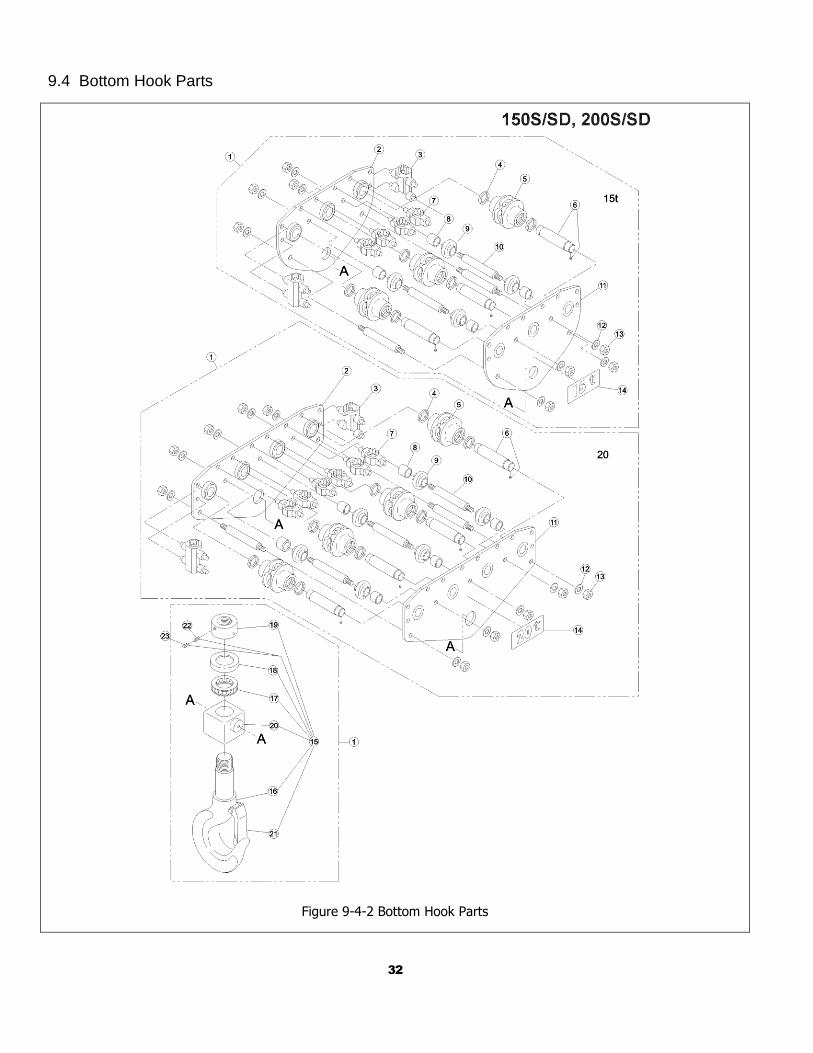
9.4 Bottom Hook Parts
Figure 9-4-2 Bottom Hook Parts
33
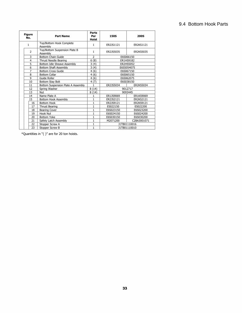
9.4 Bottom Hook Parts
Figure No.
Part Name Parts Per
Hoist
150S 200S
1 Top/Bottom Hook Complete
Assembly 1 ER2JS1121 ER2KS1121
2 Top/Bottom Suspension Plate B
Assembly 1 ER2JS5035 ER2KS5035
3 Bottom Chain Guide 2 E6S066150
4 Thrust Needle Bearing 6 (8) ER1HS9182
5 Bottom Idle Sheave Assembly 3 (4) ER2HS5052
6 Bottom Shaft Assembly 3 (4) E6S5054075
7 Bottom Cross Guide 4 (6) E6S067150
8 Bottom Collar 4 (6) E6S065150
9 Guide Roller 4 (6) E6S062075
10 Bottom Stay Bolt 4 (7) E6S038150
11 Bottom Suspension Plate A Assembly 1 ER2JS5034 ER2KS5034
12 Spring Washer 8 (14) 9012717
13 Nut 8 (14) 9093445
14 Name Plate A 1 ER1JS9069 ER1KS9069
15 Bottom Hook Assembly 1 ER2JS2121 ER2KS2121
16 Bottom Hook 1 ER2JS9121 ER2KS9121
17 Thrust Bearing 1 ES022150 ES022200
18 Bearing Cover 1 E6S023150 E6S023200
19 Hook Nut 1 E6S024150 E6S024200
20 Bottom Yoke 1 E6S030150 E6S030200
21 Safety Latch Assembly 1 M2071200 C2BA3001071
22 Stopper Screw A 1 J1TB01110016
23 Stopper Screw B 1 J1TB01110010
*Quantities in “( )” are for 20 ton hoists.
34
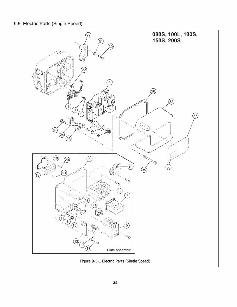
9.5 Electric Parts (Single Speed)
Figure 9-5-1 Electric Parts (Single Speed)
35
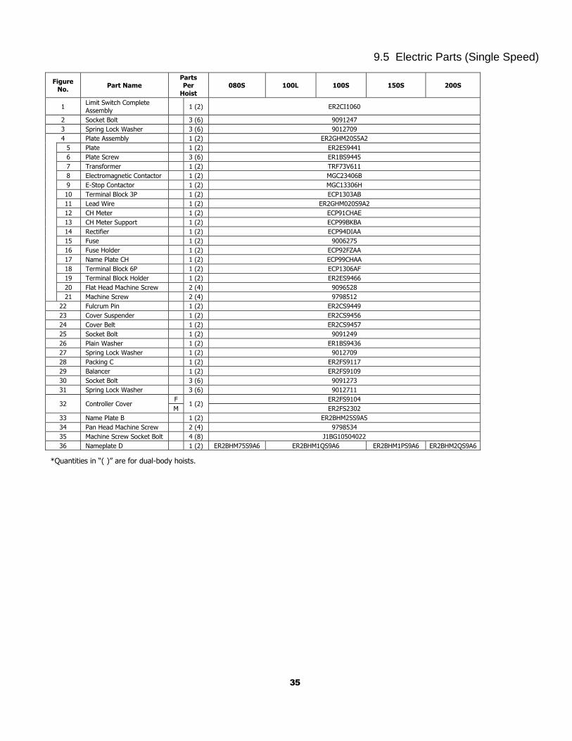
9.5 Electric Parts (Single Speed)
Figure No.
Part Name Parts Per
Hoist
080S 100L 100S 150S 200S
1 Limit Switch Complete
Assembly 1 (2) ER2CI1060
2 Socket Bolt 3 (6) 9091247
3 Spring Lock Washer 3 (6) 9012709
4 Plate Assembly 1 (2) ER2GHM20S5A2
5 Plate 1 (2) ER2ES9441
6 Plate Screw 3 (6) ER1BS9445
7 Transformer 1 (2) TRF73V611
8 Electromagnetic Contactor 1 (2) MGC23406B
9 E-Stop Contactor 1 (2) MGC13306H
10 Terminal Block 3P 1 (2) ECP1303AB
11 Lead Wire 1 (2) ER2GHM020S9A2
12 CH Meter 1 (2) ECP91CHAE
13 CH Meter Support 1 (2) ECP99BKBA
14 Rectifier 1 (2) ECP94DIAA
15 Fuse 1 (2) 9006275
16 Fuse Holder 1 (2) ECP92FZAA
17 Name Plate CH 1 (2) ECP99CHAA
18 Terminal Block 6P 1 (2) ECP1306AF
19 Terminal Block Holder 1 (2) ER2ES9466
20 Flat Head Machine Screw 2 (4) 9096528
21 Machine Screw 2 (4) 9798512
22 Fulcrum Pin 1 (2) ER2CS9449
23 Cover Suspender 1 (2) ER2CS9456
24 Cover Belt 1 (2) ER2CS9457
25 Socket Bolt 1 (2) 9091249
26 Plain Washer 1 (2) ER1BS9436
27 Spring Lock Washer 1 (2) 9012709
28 Packing C 1 (2) ER2FS9117
29 Balancer 1 (2) ER2FS9109
30 Socket Bolt 3 (6) 9091273
31 Spring Lock Washer 3 (6) 9012711
32 Controller Cover F
1 (2) ER2FS9104
M ER2FS2302
33 Name Plate B 1 (2) ER2BHM25S9A5
34 Pan Head Machine Screw 2 (4) 9798534
35 Machine Screw Socket Bolt 4 (8) J1BG10504022
36 Nameplate D 1 (2) ER2BHM75S9A6 ER2BHM1QS9A6 ER2BHM1PS9A6 ER2BHM2QS9A6
*Quantities in “( )” are for dual-body hoists.
36
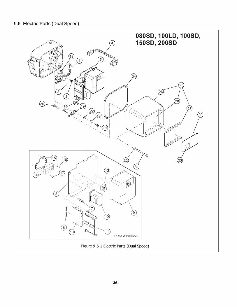
9.6 Electric Parts (Dual Speed)
Figure 9-6-1 Electric Parts (Dual Speed)
37
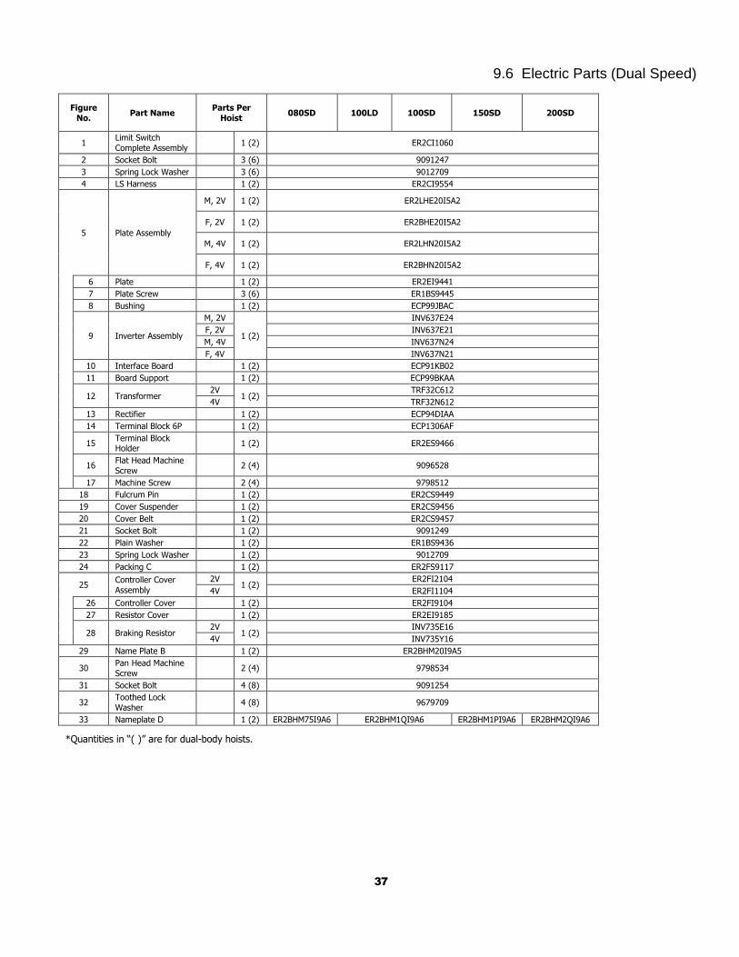
9.6 Electric Parts (Dual Speed)
Figure
No. Part Name
Parts Per
Hoist 080SD 100LD 100SD 150SD 200SD
1 Limit Switch
Complete Assembly 1 (2) ER2CI1060
2 Socket Bolt 3 (6) 9091247
3 Spring Lock Washer 3 (6) 9012709
4 LS Harness 1 (2) ER2CI9554
5 Plate Assembly
M, 2V 1 (2) ER2LHE20I5A2
F, 2V 1 (2) ER2BHE20I5A2
M, 4V 1 (2) ER2LHN20I5A2
F, 4V 1 (2) ER2BHN20I5A2
6 Plate 1 (2) ER2EI9441
7 Plate Screw 3 (6) ER1BS9445
8 Bushing 1 (2) ECP99JBAC
9 Inverter Assembly
M, 2V
1 (2)
INV637E24
F, 2V INV637E21
M, 4V INV637N24
F, 4V INV637N21
10 Interface Board 1 (2) ECP91KB02
11 Board Support 1 (2) ECP99BKAA
12 Transformer 2V
1 (2) TRF32C612
4V TRF32N612
13 Rectifier 1 (2) ECP94DIAA
14 Terminal Block 6P 1 (2) ECP1306AF
15 Terminal Block Holder
1 (2) ER2ES9466
16 Flat Head Machine
Screw 2 (4) 9096528
17 Machine Screw 2 (4) 9798512
18 Fulcrum Pin 1 (2) ER2CS9449
19 Cover Suspender 1 (2) ER2CS9456
20 Cover Belt 1 (2) ER2CS9457
21 Socket Bolt 1 (2) 9091249
22 Plain Washer 1 (2) ER1BS9436
23 Spring Lock Washer 1 (2) 9012709
24 Packing C 1 (2) ER2FS9117
25 Controller Cover
Assembly
2V 1 (2)
ER2FI2104
4V ER2FI1104
26 Controller Cover 1 (2) ER2FI9104
27 Resistor Cover 1 (2) ER2EI9185
28 Braking Resistor 2V
1 (2) INV735E16
4V INV735Y16
29 Name Plate B 1 (2) ER2BHM20I9A5
30 Pan Head Machine
Screw 2 (4) 9798534
31 Socket Bolt 4 (8) 9091254
32 Toothed Lock
Washer 4 (8) 9679709
33 Nameplate D 1 (2) ER2BHM75I9A6 ER2BHM1QI9A6 ER2BHM1PI9A6 ER2BHM2QI9A6
*Quantities in “( )” are for dual-body hoists.
38
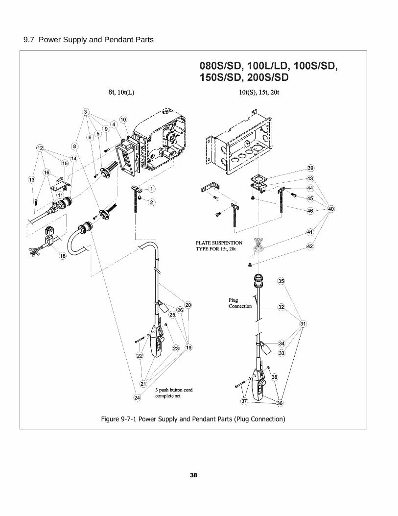
9.7 Power Supply and Pendant Parts
Figure 9-7-1 Power Supply and Pendant Parts (Plug Connection)
39
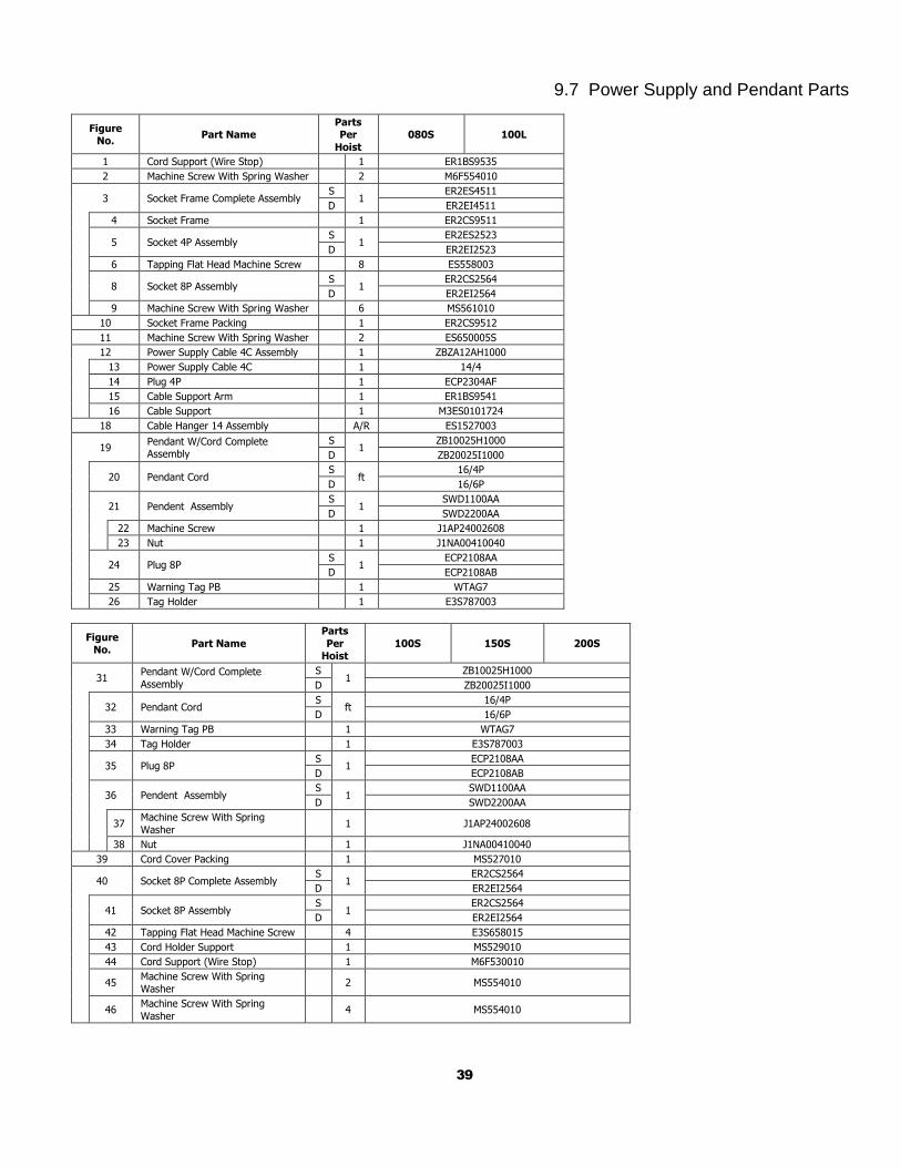
9.7 Power Supply and Pendant Parts
Figure No.
Part Name Parts Per
Hoist
080S 100L
1 Cord Support (Wire Stop) 1 ER1BS9535
2 Machine Screw With Spring Washer 2 M6F554010
3 Socket Frame Complete Assembly S
1 ER2ES4511
D ER2EI4511
4 Socket Frame 1 ER2CS9511
5 Socket 4P Assembly S
1 ER2ES2523
D ER2EI2523
6 Tapping Flat Head Machine Screw 8 ES558003
8 Socket 8P Assembly S
1 ER2CS2564
D ER2EI2564
9 Machine Screw With Spring Washer 6 MS561010
10 Socket Frame Packing 1 ER2CS9512
11 Machine Screw With Spring Washer 2 ES650005S
12 Power Supply Cable 4C Assembly 1 ZBZA12AH1000
13 Power Supply Cable 4C 1 14/4
14 Plug 4P 1 ECP2304AF
15 Cable Support Arm 1 ER1BS9541
16 Cable Support 1 M3ES0101724
18 Cable Hanger 14 Assembly A/R ES1527003
19 Pendant W/Cord Complete Assembly
S 1
ZB10025H1000
D ZB20025I1000
20 Pendant Cord S
ft 16/4P
D 16/6P
21 Pendent Assembly S
1 SWD1100AA
D SWD2200AA
22 Machine Screw 1 J1AP24002608
23 Nut 1 J1NA00410040
24 Plug 8P S
1 ECP2108AA
D ECP2108AB
25 Warning Tag PB 1 WTAG7
26 Tag Holder 1 E3S787003
Figure No.
Part Name
Parts
Per Hoist
100S 150S 200S
31 Pendant W/Cord Complete
Assembly
S 1
ZB10025H1000
D ZB20025I1000
32 Pendant Cord S
ft 16/4P
D 16/6P
33 Warning Tag PB 1 WTAG7
34 Tag Holder 1 E3S787003
35 Plug 8P S
1 ECP2108AA
D ECP2108AB
36 Pendent Assembly S
1 SWD1100AA
D SWD2200AA
37
Machine Screw With Spring
Washer 1 J1AP24002608
38 Nut 1 J1NA00410040
39 Cord Cover Packing 1 MS527010
40 Socket 8P Complete Assembly S
1 ER2CS2564
D ER2EI2564
41 Socket 8P Assembly S
1 ER2CS2564
D ER2EI2564
42 Tapping Flat Head Machine Screw 4 E3S658015
43 Cord Holder Support 1 MS529010
44 Cord Support (Wire Stop) 1 M6F530010
45 Machine Screw With Spring Washer
2 MS554010
46 Machine Screw With Spring
Washer 4 MS554010
40
9.7 Power Supply and Pendant Parts
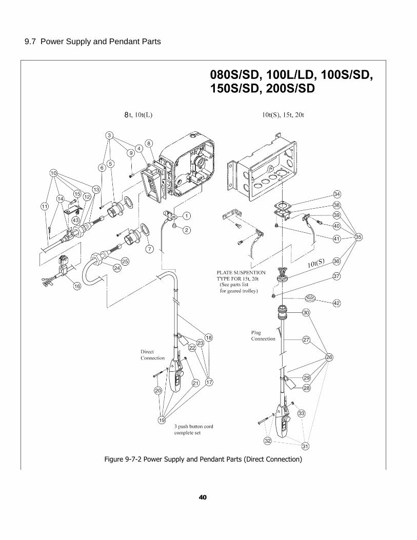
Figure 9-7-2 Power Supply and Pendant Parts (Direct Connection)
41
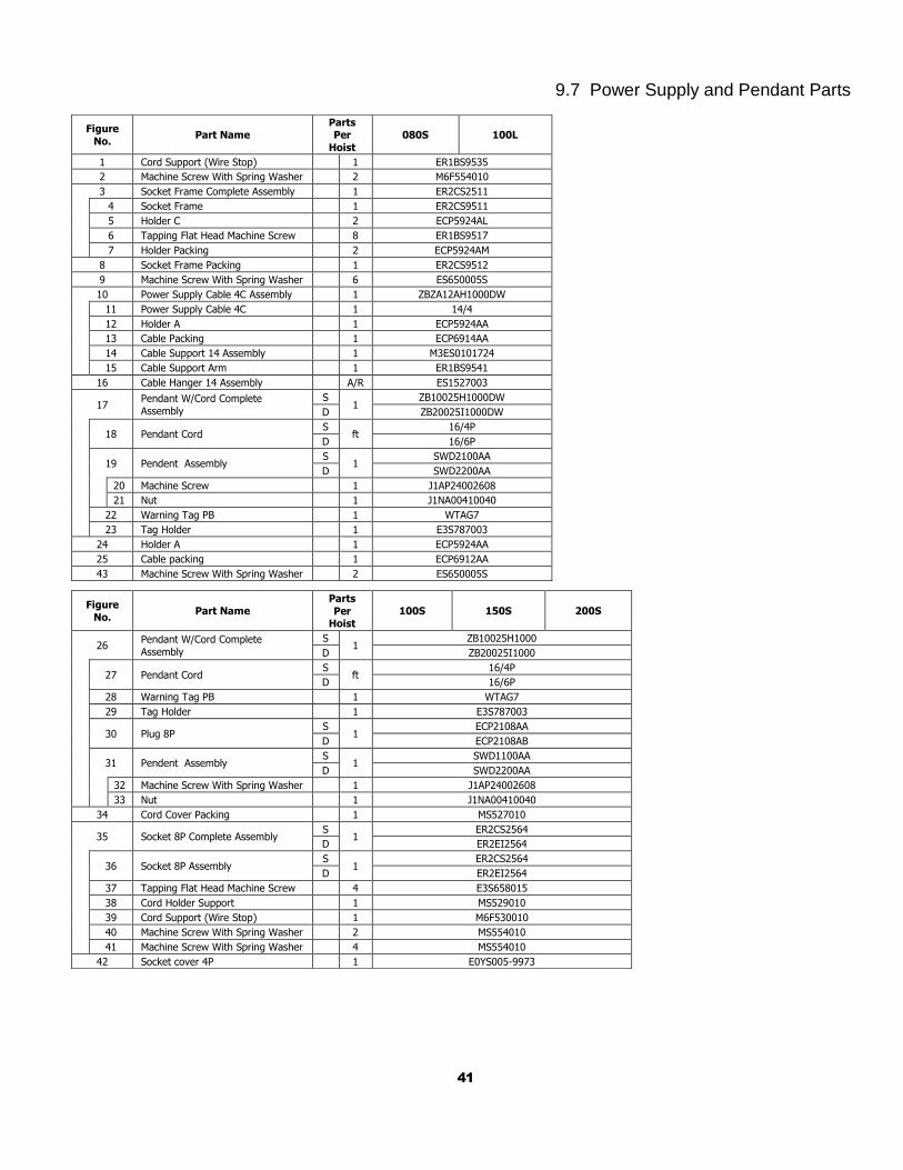
9.7 Power Supply and Pendant Parts
Figure
No. Part Name
Parts Per
Hoist
080S 100L
1 Cord Support (Wire Stop) 1 ER1BS9535
2 Machine Screw With Spring Washer 2 M6F554010
3 Socket Frame Complete Assembly 1 ER2CS2511
4 Socket Frame 1 ER2CS9511
5 Holder C 2 ECP5924AL
6 Tapping Flat Head Machine Screw 8 ER1BS9517
7 Holder Packing 2 ECP5924AM
8 Socket Frame Packing 1 ER2CS9512
9 Machine Screw With Spring Washer 6 ES650005S
10 Power Supply Cable 4C Assembly 1 ZBZA12AH1000DW
11 Power Supply Cable 4C 1 14/4
12 Holder A 1 ECP5924AA
13 Cable Packing 1 ECP6914AA
14 Cable Support 14 Assembly 1 M3ES0101724
15 Cable Support Arm 1 ER1BS9541
16 Cable Hanger 14 Assembly A/R ES1527003
17 Pendant W/Cord Complete
Assembly
S 1
ZB10025H1000DW
D ZB20025I1000DW
18 Pendant Cord S
ft 16/4P
D 16/6P
19 Pendent Assembly S
1 SWD2100AA
D SWD2200AA
20 Machine Screw 1 J1AP24002608
21 Nut 1 J1NA00410040
22 Warning Tag PB 1 WTAG7
23 Tag Holder 1 E3S787003
24 Holder A 1 ECP5924AA
25 Cable packing 1 ECP6912AA
43 Machine Screw With Spring Washer 2 ES650005S
Figure
No. Part Name
Parts
Per Hoist
100S 150S 200S
26 Pendant W/Cord Complete
Assembly
S 1
ZB10025H1000
D ZB20025I1000
27 Pendant Cord S
ft 16/4P
D 16/6P
28 Warning Tag PB 1 WTAG7
29 Tag Holder 1 E3S787003
30 Plug 8P S
1 ECP2108AA
D ECP2108AB
31 Pendent Assembly S
1 SWD1100AA
D SWD2200AA
32 Machine Screw With Spring Washer 1 J1AP24002608
33 Nut 1 J1NA00410040
34 Cord Cover Packing 1 MS527010
35 Socket 8P Complete Assembly S
1 ER2CS2564
D ER2EI2564
36 Socket 8P Assembly S
1 ER2CS2564
D ER2EI2564
37 Tapping Flat Head Machine Screw 4 E3S658015
38 Cord Holder Support 1 MS529010
39 Cord Support (Wire Stop) 1 M6F530010
40 Machine Screw With Spring Washer 2 MS554010
41 Machine Screw With Spring Washer 4 MS554010
42 Socket cover 4P 1 E0YS005-9973
42
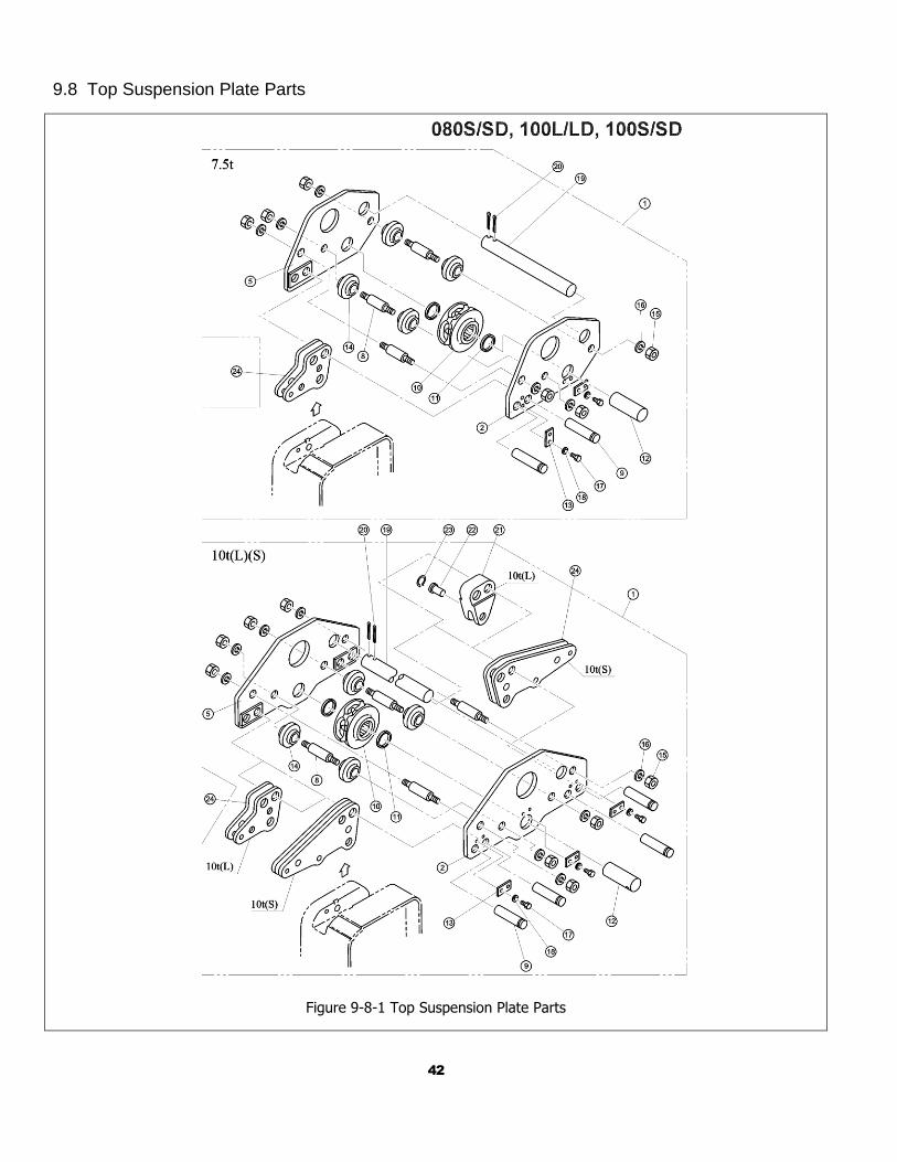
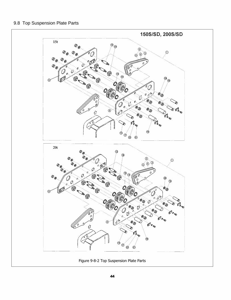
9.8 Top Suspension Plate Parts
Figure 9-8-1 Top Suspension Plate Parts
43
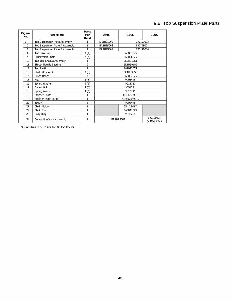
9.8 Top Suspension Plate Parts
Figure No.
Part Name Parts Per
Hoist
080S 100L 100S
1 Top Suspension Plate Assembly 1 ER2HS1003 ER2IS1003
2 Top Suspension Plate A Assembly 1 ER2HS5003 ER2IS5003
5 Top Suspension Plate B Assembly 1 ER2HS5004 ER2IS5004
8 Top Stay Bolt 3 (4) E6S007075
9 Suspension Shaft 2 (4) E6S008075
10 Top Idle Sheave Assembly 1 ER2HS5051
11 Thrust Needle Bearing 2 ER1HS9182
12 Top Shaft 1 E6S053075
13 Shaft Stopper A 2 (3) ER1HS9056
14 Guide Roller 4 E6S062075
15 Nut 6 (8) 9093445
16 Spring Washer 6 (8) 9012717
17 Socket Bolt 4 (6) 9091271
18 Spring Washer 4 (6) 9012711
19 Stopper Shaft 1 E6SE075S9010
Stopper Shaft (300) 1 E7SE075S9019
20 Split Pin 2 9009448
21 Chain Holder 1 ER1IL9017
22 Chain Pin 1 E6S041075
23 Snap Ring 1 9047221
24 Connection Yoke Assembly 1 ER2HS5005 ER2IS5005
(2 Required)
*Quantities in “( )” are for 10 ton hoists.
44
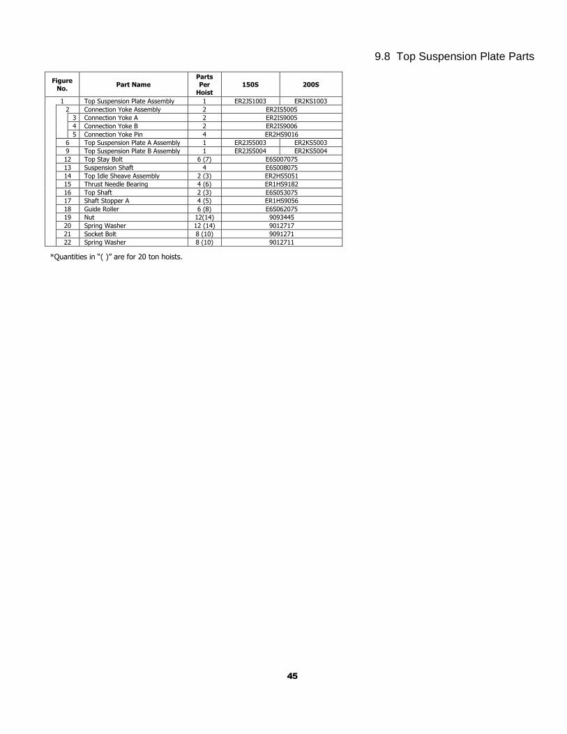
9.8 Top Suspension Plate Parts
Figure 9-8-2 Top Suspension Plate Parts
45
9.8 Top Suspension Plate Parts
Figure No.
Part Name Parts Per
Hoist
150S 200S
1 Top Suspension Plate Assembly 1 ER2JS1003 ER2KS1003
2 Connection Yoke Assembly 2 ER2IS5005
3 Connection Yoke A 2 ER2IS9005
4 Connection Yoke B 2 ER2IS9006
5 Connection Yoke Pin 4 ER2HS9016
6 Top Suspension Plate A Assembly 1 ER2JS5003 ER2KS5003
9 Top Suspension Plate B Assembly 1 ER2JS5004 ER2KS5004
12 Top Stay Bolt 6 (7) E6S007075
13 Suspension Shaft 4 E6S008075
14 Top Idle Sheave Assembly 2 (3) ER2HS5051
15 Thrust Needle Bearing 4 (6) ER1HS9182
16 Top Shaft 2 (3) E6S053075
17 Shaft Stopper A 4 (5) ER1HS9056
18 Guide Roller 6 (8) E6S062075
19 Nut 12(14) 9093445
20 Spring Washer 12 (14) 9012717
21 Socket Bolt 8 (10) 9091271
22 Spring Washer 8 (10) 9012711
*Quantities in “( )” are for 20 ton hoists.
46
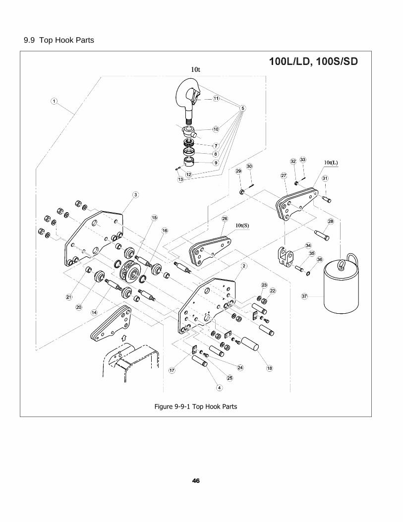
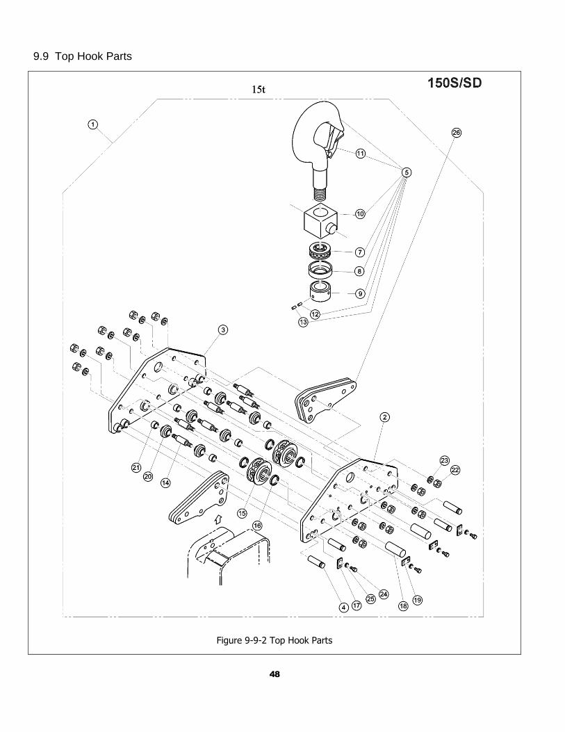
9.9 Top Hook Parts
Figure 9-9-1 Top Hook Parts
47
9.9 Top Hook Parts
Figure No.
Part Name Parts
Per Hoist
100L 100S
1 Top Hook Complete Assembly 1 ER2IS1011
2 Top Suspension Plate A Assembly 1 ER2IS5011
3 Top Suspension Plate B Assembly 1 ER2IS5012
4 Suspender Shaft B 4 E6S013100
5 Top/Bottom Hook Assembly 1 ER2IS2121
7 Thrust Bearing 1 ES022100
8 Bearing Cover 1 E6S023100
9 Hook Nut 1 ES024100
10 Bottom Yoke 1 E6S030100
11 Safety Latch Assembly 1 C2BA1501071
12 Stopper Screw A 1 J1TB01110016
13 Stopper Screw B 1 J1TB01110008
14 Bottom Stay Bolt 4 E6S038075 15 Bottom Idle Sheave Assembly 1 ER2HS5052
16 Thrust Needle Bearing 2 ER1HS9182
17 Shaft Stopper A 3 ER1IS9056
18 Top Shaft B 1 E6S057100
20 Guide Roller 4 E6S062075
21 Bottom Collar 4 E6S065075
22 Nut 8 9093445
23 Spring Washer 8 9012717
24 Socket Bolt 6 9091271
25 Spring Washer 6 9012711
26 Connection Yoke Assembly 2 ER2IS5005
27 Connection Yoke Assembly 1 ER2IL5155
28 Yoke Bolt 1 ER1ES9032
29 Slotted Nut 1 ES088020L
30 Split Pin 1 9009436
31 Chain Pin 1 ES041050
32 Slotted Nut 1 M2049030
33 Split Pin 1 9009424
34 Chain Holder 1 ER1IL9171
35 Chain Pin 1 E6S041075
36 Snap Ring 1 9047221
37 Balance Weight Assembly 1 7021002
48
9.9 Top Hook Parts
Figure 9-9-2 Top Hook Parts
49
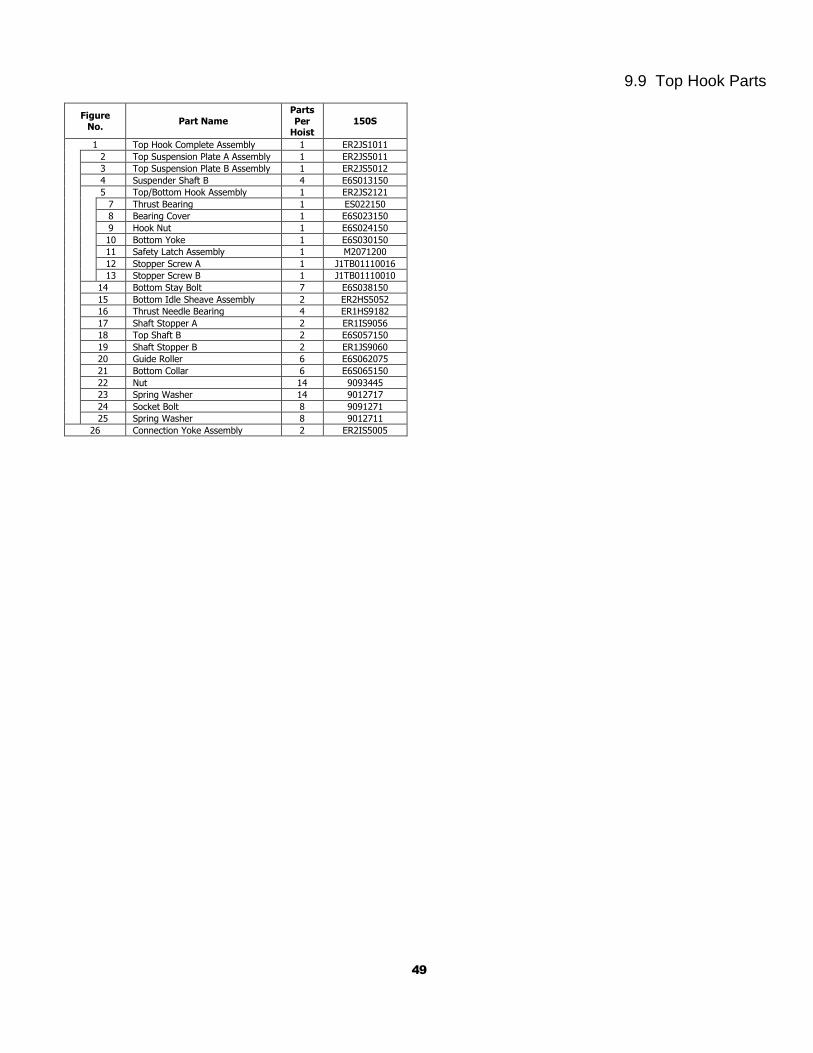
9.9 Top Hook Parts
Figure No.
Part Name Parts
Per Hoist
150S
1 Top Hook Complete Assembly 1 ER2JS1011
2 Top Suspension Plate A Assembly 1 ER2JS5011
3 Top Suspension Plate B Assembly 1 ER2JS5012
4 Suspender Shaft B 4 E6S013150
5 Top/Bottom Hook Assembly 1 ER2JS2121
7 Thrust Bearing 1 ES022150
8 Bearing Cover 1 E6S023150
9 Hook Nut 1 E6S024150
10 Bottom Yoke 1 E6S030150
11 Safety Latch Assembly 1 M2071200
12 Stopper Screw A 1 J1TB01110016
13 Stopper Screw B 1 J1TB01110010
14 Bottom Stay Bolt 7 E6S038150
15 Bottom Idle Sheave Assembly 2 ER2HS5052
16 Thrust Needle Bearing 4 ER1HS9182
17 Shaft Stopper A 2 ER1IS9056
18 Top Shaft B 2 E6S057150
19 Shaft Stopper B 2 ER1JS9060
20 Guide Roller 6 E6S062075
21 Bottom Collar 6 E6S065150
22 Nut 14 9093445
23 Spring Washer 14 9012717
24 Socket Bolt 8 9091271
25 Spring Washer 8 9012711
26 Connection Yoke Assembly 2 ER2IS5005
50
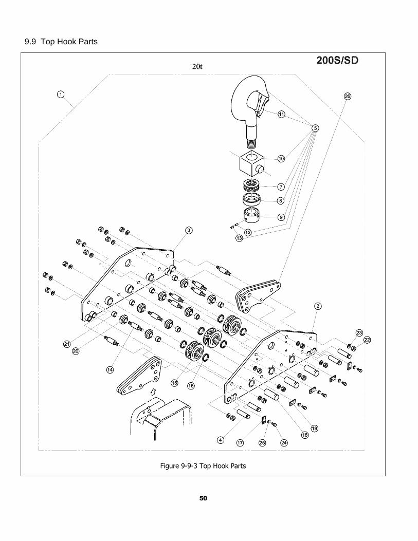
9.9 Top Hook Parts
Figure 9-9-3 Top Hook Parts
51
9.9 Top Hook Parts
Figure No.
Part Name Parts Per
Hoist
200S
1 Top Hook Complete Assembly 1 ER2KS1011
2 Top Suspension Plate A Assembly 1 ER2KS5011
3 Top Suspension Plate B Assembly 1 ER2KS5012
4 Suspender Shaft B 4 E6S013150
5 Top/Bottom Hook Assembly 1 ER2KS2121
7 Thrust Bearing 1 E6S038150
8 Bearing Cover 1 E6S023200
9 Hook Nut 1 E6S024200
10 Bottom Yoke 1 E6S030200
11 Safety Latch Assembly 1 C2BA3001071
12 Stopper Screw A 1 J1TB01110016
13 Stopper Screw B 1 J1TB01110010
14 Bottom Stay Bolt 8 E6S038150
15 Bottom Idle Sheave Assembly 3 ER2HS5052
16 Thrust Needle Bearing 6 ER1HS9182
17 Shaft Stopper A 2 ER1IS9056
18 Top Shaft B 3 E6S067150
19 Shaft Stopper B 3 ER1JS9060
20 Guide Roller 8 E6S062075
21 Bottom Collar 8 E6S065150
22 Nut 16 9093445
23 Spring Washer 16 9012717
24 Socket Bolt 10 9091271
25 Spring Washer 10 9012711
26 Connection Yoke Assembly 2 ER2IS5005
52
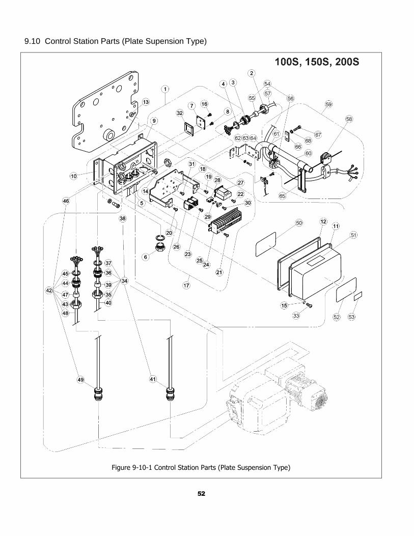
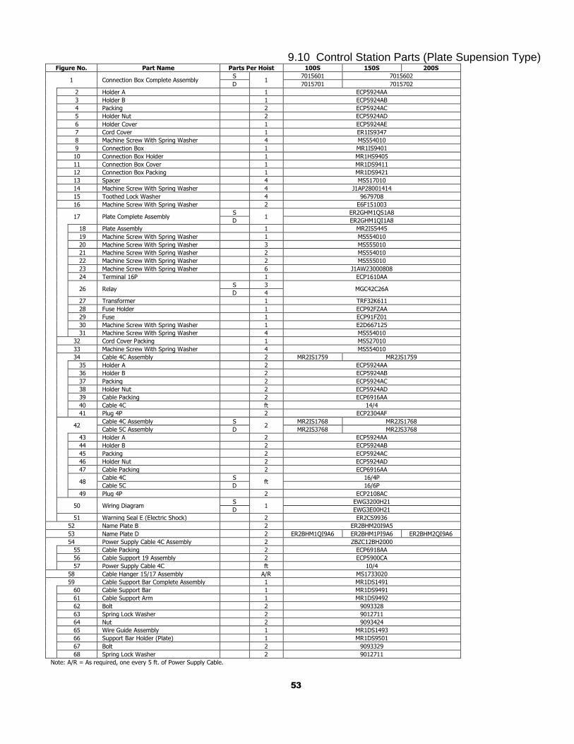
9.10 Control Station Parts (Plate Supension Type)
Figure 9-10-1 Control Station Parts (Plate Suspension Type)
53
9.10 Control Station Parts (Plate Supension Type) Figure No. Part Name Parts Per Hoist 100S 150S 200S
1 Connection Box Complete Assembly S
1 7015601 7015602
D 7015701 7015702
2 Holder A 1 ECP5924AA
3 Holder B 1 ECP5924AB
4 Packing 2 ECP5924AC
5 Holder Nut 2 ECP5924AD
6 Holder Cover 1 ECP5924AE
7 Cord Cover 1 ER1IS9347
8 Machine Screw With Spring Washer 4 MS554010
9 Connection Box 1 MR1IS9401
10 Connection Box Holder 1 MR1HS9405
11 Connection Box Cover 1 MR1DS9411
12 Connection Box Packing 1 MR1DS9421
13 Spacer 4 MS517010
14 Machine Screw With Spring Washer 4 J1AP28001414
15 Toothed Lock Washer 4 9679708
16 Machine Screw With Spring Washer 2 E6F151003
17 Plate Complete Assembly S
1 ER2GHM1QS1A8
D ER2GHM1QI1A8
18 Plate Assembly 1 MR2IS5445
19 Machine Screw With Spring Washer 1 MS554010
20 Machine Screw With Spring Washer 3 MS555010
21 Machine Screw With Spring Washer 2 MS554010
22 Machine Screw With Spring Washer 2 MS555010
23 Machine Screw With Spring Washer 6 J1AW23000808
24 Terminal 16P 1 ECP1610AA
26 Relay S 3
MGC42C26A D 4
27 Transformer 1 TRF32K611
28 Fuse Holder 1 ECP92FZAA
29 Fuse 1 ECP91FZ01
30 Machine Screw With Spring Washer 1 E2D667125
31 Machine Screw With Spring Washer 4 MS554010
32 Cord Cover Packing 1 MS527010
33 Machine Screw With Spring Washer 4 MS554010
34 Cable 4C Assembly 2 MR2IS1759 MR2JS1759
35 Holder A 2 ECP5924AA
36 Holder B 2 ECP5924AB
37 Packing 2 ECP5924AC
38 Holder Nut 2 ECP5924AD
39 Cable Packing 2 ECP6916AA
40 Cable 4C ft 14/4
41 Plug 4P 2 ECP2304AF
42 Cable 4C Assembly S
2 MR2IS1768 MR2JS1768
Cable 5C Assembly D MR2IS3768 MR2JS3768
43 Holder A 2 ECP5924AA
44 Holder B 2 ECP5924AB
45 Packing 2 ECP5924AC
46 Holder Nut 2 ECP5924AD
47 Cable Packing 2 ECP6916AA
48 Cable 4C S
ft 16/4P
Cable 5C D 16/6P
49 Plug 4P 2 ECP2108AC
50 Wiring Diagram S
1 EWG3200H21
D EWG3E00H21
51 Warning Seal E (Electric Shock) 2 ER2CS9936
52 Name Plate B 2 ER2BHM20I9A5
53 Name Plate D 2 ER2BHM1QI9A6 ER2BHM1PI9A6 ER2BHM2QI9A6
54 Power Supply Cable 4C Assembly 2 ZBZC12BH2000
55 Cable Packing 2 ECP6918AA
56 Cable Support 19 Assembly 2 ECP5900CA
57 Power Supply Cable 4C ft 10/4
58 Cable Hanger 15/17 Assembly A/R MS1733020
59 Cable Support Bar Complete Assembly 1 MR1DS1491
60 Cable Support Bar 1 MR1DS9491
61 Cable Support Arm 1 MR1DS9492
62 Bolt 2 9093328
63 Spring Lock Washer 2 9012711
64 Nut 2 9093424
65 Wire Guide Assembly 1 MR1DS1493
66 Support Bar Holder (Plate) 1 MR1DS9501
67 Bolt 2 9093329
68 Spring Lock Washer 2 9012711
Note: A/R = As required, one every 5 ft. of Power Supply Cable.
54
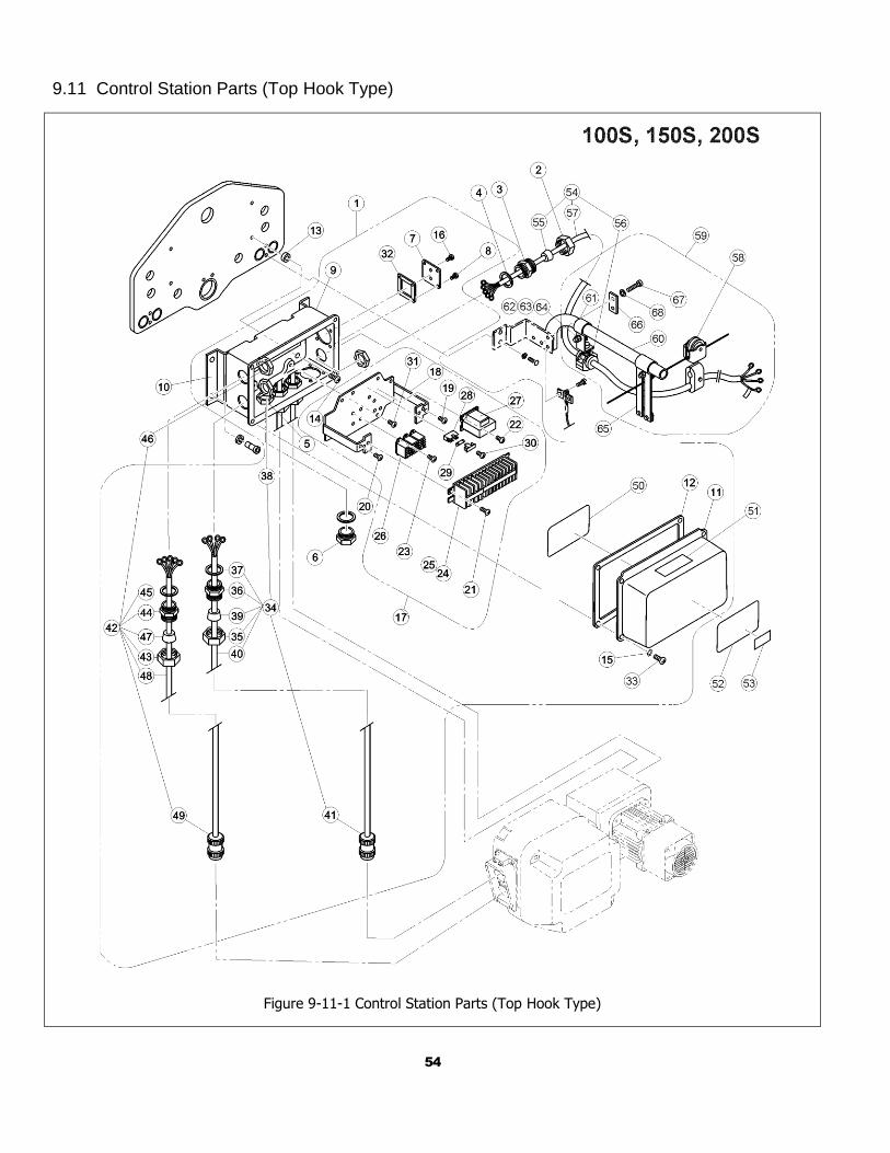
9.11 Control Station Parts (Top Hook Type)
Figure 9-11-1 Control Station Parts (Top Hook Type)
55
9.11 Control Station Parts (Top Hook Type) Figure No. Part Name Parts Per Hoist 100S 150S 200S
1 Connection Box Complete Assembly S
1 7015601 7015602
D 7015701 7015702
2 Holder A 1 ECP5924AA
3 Holder B 1 ECP5924AB
4 Packing 2 ECP5924AC
5 Holder Nut 2 ECP5924AD
6 Holder Cap 1 ECP5924AE
7 Cord Cover 1 ER1IS9347
8 Machine Screw With Spring Washer 4 MS554010
9 Connection Box 1 MR1IS9401
10 Connection Box Holder 1 MR1HS9405
11 Connection Box Cover 1 MR1DS9411
12 Connection Box Packing 1 MR1DS9421
13 Spacer 4 MS517010
14 Machine Screw With Spring Washer 4 J1AP28001414
15 Toothed Lock Washer 4 9679708
16 Machine Screw With Spring Washer 2 E6F151003
17 Plate Complete Assembly S
1 ER2GHM1QS1A8
D ER2GHM1QI1A8
18 Plate Assembly 1 MR2IS5445
19 Machine Screw With Spring Washer 1 MS554010
20 Machine Screw With Spring Washer 3 MS555010
21 Machine Screw With Spring Washer 2 MS554010
22 Machine Screw With Spring Washer 2 MS555010
23 Machine Screw With Spring Washer 6 J1AW23000808
24 Terminal 16P 1 ECP1610AA
26 Relay S 3
MGC42C26A D 4
27 Transformer 1 TRF32K611
28 Fuse Holder 1 ECP92FZAA
29 Fuse 1 ECP91FZ01
30 Machine Screw With Spring Washer 1 E2D667125
31 Machine Screw With Spring Washer 4 MS554010
32 Cord Cover Packing 1 MS527010
33 Machine Screw With Spring Washer 4 MS554010
34 Cable 4C Assembly 2 MR2IS1759 MR2JS1759
35 Holder A 2 ECP5924AA
36 Holder B 2 ECP5924AB
37 Packing 2 ECP5924AC
38 Holder Nut 2 ECP5924AD
39 Cable Packing 2 ECP6916AA
40 Relay Cable 4C ft 14/4
41 Plug 4P 2 ECP2304AF
42 Cable 4C Assembly S
2 MR2IS1768 MR2JS1768
Cable 5C Assembly D MR2IS3768 MR2JS3768
43 Holder A 2 ECP5924AA
44 Holder B 2 ECP5924AB
45 Packing 2 ECP5924AC
46 Holder Nut 2 ECP5924AD
47 Cable Packing 2 ECP6916AA
48 Cable 4C S
ft 16/4P
Cable 5C D 16/6P
49 Plug 4P 2 ECP2108AC
50 Wiring Diagram S
1 EWG3200H21
D EWG3E00H21
51 Warning Seal E (Electric Shock) 2 ER2CS9936
52 Name Plate B 2 ER2BHM20I9A5
53 Name Plate D 2 ER2BHM1QI9A6 ER2BHM1PI9A6 ER2BHM2QI9A6
54 Power Supply Cable 4C Assembly 2 ZBZC12BH2000
55 Cable Packing 2 ECP6918AA
56 Cable Support 19 Assembly 2 ECP5900CA
57 Power Supply Cable 4C ft 10/4
58 Cable Hanger 15/17 Assembly A/R MS1733020
59 Cable Support Bar Complete Assembly 1 MR1DS1491
60 Cable Support Bar 1 MR1DS9491
61 Cable Support Arm 1 MR1DS9492
62 Bolt 2 9093328
63 Spring Lock Washer 2 9012711
64 Nut 2 9093424
65 Wire Guide Assembly 1 MR1DS1493
66 Support Bar Holder (Plate) 1 MR1DS9501
67 Bolt 2 9093329
68 Spring Lock Washer 2 9012711
Note: A/R = As required, one every 5 ft. of Power Supply Cable.
56
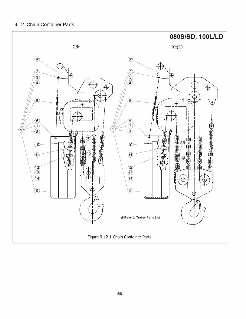
9.12 Chain Container Parts
Figure 9-12-1 Chain Container Parts
57
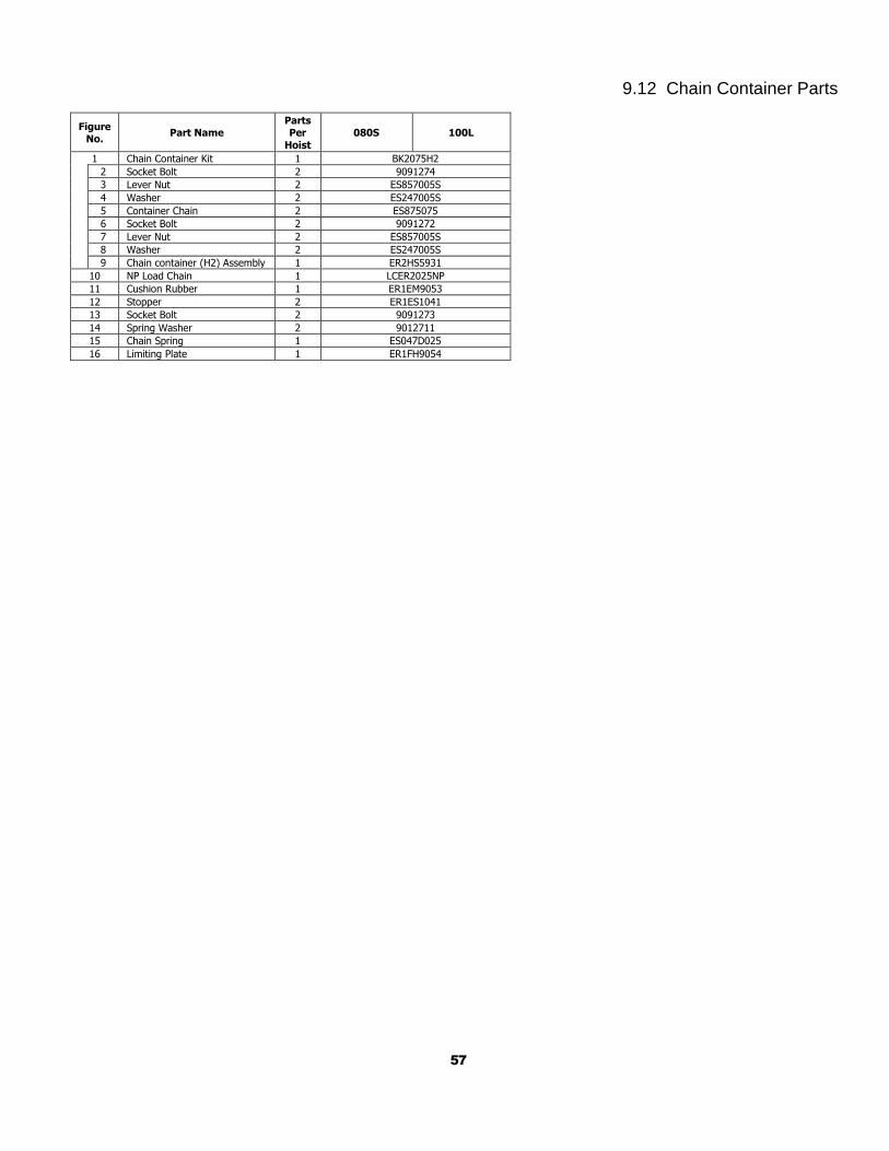
9.12 Chain Container Parts
Figure No.
Part Name Parts Per
Hoist
080S 100L
1 Chain Container Kit 1 BK2075H2
2 Socket Bolt 2 9091274
3 Lever Nut 2 ES857005S
4 Washer 2 ES247005S
5 Container Chain 2 ES875075
6 Socket Bolt 2 9091272
7 Lever Nut 2 ES857005S
8 Washer 2 ES247005S
9 Chain container (H2) Assembly 1 ER2HS5931
10 NP Load Chain 1 LCER2025NP
11 Cushion Rubber 1 ER1EM9053
12 Stopper 2 ER1ES1041
13 Socket Bolt 2 9091273
14 Spring Washer 2 9012711
15 Chain Spring 1 ES047D025
16 Limiting Plate 1 ER1FH9054
58
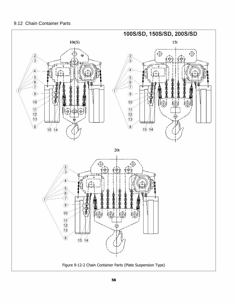
9.12 Chain Container Parts
Figure 9-12-2 Chain Container Parts (Plate Suspension Type)
59
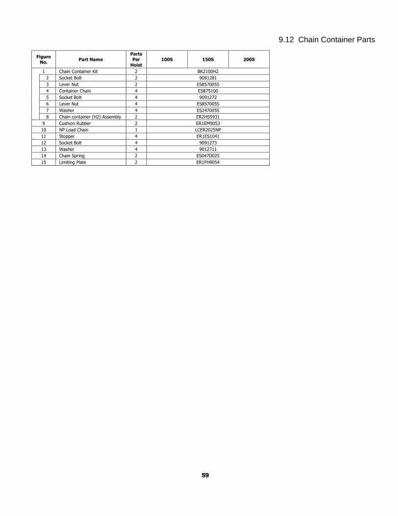
9.12 Chain Container Parts
Figure No.
Part Name Parts Per
Hoist
100S 150S 200S
1 Chain Container Kit 2 BK2100H2
2 Socket Bolt 2 9091281
3 Lever Nut 2 ES857005S
4 Container Chain 4 ES875100
5 Socket Bolt 4 9091272
6 Lever Nut 4 ES857005S
7 Washer 4 ES247005S
8 Chain container (H2) Assembly 2 ER2HS5931
9 Cushion Rubber 2 ER1EM9053
10 NP Load Chain 1 LCER2025NP
11 Stopper 4 ER1ES1041
12 Socket Bolt 4 9091273
13 Washer 4 9012711
14 Chain Spring 2 ES047D025
15 Limiting Plate 2 ER1FH9054

Harrington Hoists, Inc. 401 West End Avenue Manheim, PA 17545
www.harringtonhoists.com Toll Free: 800-233-3010 Phone: 717-665-2000
Fax: 717-665-2861
ER2LCOMSup-ENG


![[XLS] · Web viewHOIST HOIST EQUIPMENT ACTUATOR, MLG HOIST HOIST EQUIPMENT - ACTUATOR, MLG HOIST HOIST - CARDAN PIN HOIST HOIST-CARDAN PIN HOIST HOIST-DEVICE,FLAP TRACK 2-5 HOIST](https://img.pdfslide.us/doc/110x75/5b1fa5177f8b9aa64c8b4800/xls-web-viewhoist-hoist-equipment-actuator-mlg-hoist-hoist-equipment-actuator.jpg)