Embed Size (px)
Citation preview

Notice
Note that when converting this document from its original format to a .pdf file, some minor font and format changes may occur causing slight variations from the original printed document. When viewing and printing this document, we cannot guarantee that your specific PC or printer will support all of the fonts or graphics. Therefore, when you view the document, fonts may be substituted and your individual printer may not have the capability to print the document correctly.
NEC America, Inc.
Stock Number 750824
Document Revision 2
LEAST COST ROUTING MANUAL
and


NEC America, Inc. reserves the right to change the specifications, functions, orfeatures at any time without notice.
NEC America, Inc. has prepared this document for use by its employees andcustomers. The information contained herein is the property of NEC America, Inc.and shall not be reproduced without prior written approval from NEC America, Inc.
Electra Elite IPK, and Electra Elite registered trademarks of NEC America, Inc.Windows is a registered trademark of Microsoft Corporation.
Copyright 2003
NEC Infrontia, Inc.6535 N. State Highway 161
Irving, TX 75039-2402
Technology Development

LCR Manual i
___________________________________________________________________________________
___________________________________________________________________________________
TABLE OF CONTENTS
Chapter 1 Introduction
Section 1 Overview ................................................................................................ 1-1
Section 2 LCR Overview ....................................................................................... 1-1
2.1 Features Added with Software Versions ................................................1-1
2.1.1 LCR PC Programming Version ..................................................1-1
2.1.2 MIFM Software ...........................................................................1-2
2.1.3 Software Matrix ........................................................................1-3
2.2 MIFM-U10 ETU...................................................................................... 1-3
2.2.1 General ......................................................................................1-3
2.3 Programming System for LCR............................................................... 1-4
2.3.1 CPUI( )-U( ) ETU (Electra Elite IPK) ..........................................1-4
2.3.2 Programming System Memory Blocks .......................................1-5
2.4 Numbering Plan Support ....................................................................... 1-5
2.5 System/Station Speed Dial Considerations ........................................... 1-5
Chapter 2 PC Requirements and Software Installation
Section 1 PC Requirements .................................................................................. 2-1
1.1 PC Requirements ..................................................................................2-1
Section 2 Software Installation .............................................................................. 2-1
2.1 Installing the Electra Elite IPK LCR Software ........................................2-1
Section 3 Starting the LCR Program from a PC .................................................... 2-2
3.1 Starting LCR ..........................................................................................2-2
Document Revision 2 Electra Elite IPK___________________________________________________________________________________
ii Table of Contents
___________________________________________________________________________________
Chapter 3 PC to KSU Communication Methods
Section 1 Direct Connect .......................................................................................3-1
Section 2 Remote Connection (Built-in Modem Unit) ............................................3-2
Section 3 Remote Connection (External Modem) .................................................3-3
Section 4 LAN/WAN Connection ...........................................................................3-4
Chapter 4 Configuring the Communication Methods
Section 1 Direct Connection (Configuration) .........................................................4-1
1.1 Setting LCR for Direct Connection .........................................................4-1
Section 2 Remote Connection (via Built-in Modem Unit Configuration) ................4-3
2.1 Configuring LCR to Dial Remotely .........................................................4-4
Section 3 Remote Connection (via External Modem Configuration .......................4-4
Section 4 LAN/WAN Connection (Configuration) ..................................................4-5
4.1 Configuring LCR to Communicate via LAN/WAN ..................................4-5
Chapter 5 LCR Program Menus
Section 1 General Information ...............................................................................5-1
Section 2 LCR Program Screens ...........................................................................5-1
Section 3 Toolbar ...................................................................................................5-3
Section 4 LCR Pulldown Menus ............................................................................5-4
Chapter 6 LCR Programming
Section 1 Starting LCR Program ...........................................................................6-1
1.1 Starting from the Windows Desktop Screen ..........................................6-1
Section 2 Logging into the LCR Program ..............................................................6-1
Electra Elite IPK Document Revision 2
Key-Common Channel Interoffice Signaling Manual - iii
___________________________________________________________________________________
___________________________________________________________________________________
LCR Manual iii
___________________________________________________________________________________
2.1 Entering the Password for the First Time .............................................. 6-2
2.2 Changing an Existing Password ............................................................ 6-2
Section 3 Exiting the LCR Program ....................................................................... 6-2
Section 4 Errors while Entering Data ..................................................................... 6-3
Section 5 Programming LCR Tables ..................................................................... 6-4
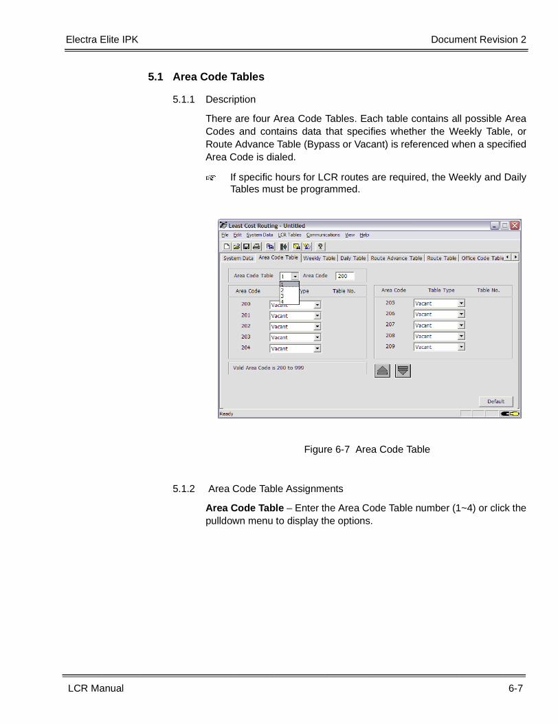
5.1 Area Code Tables ..................................................................................6-7
5.1.1 Description .................................................................................6-7
5.1.2 Area Code Table Assignments .................................................6-7
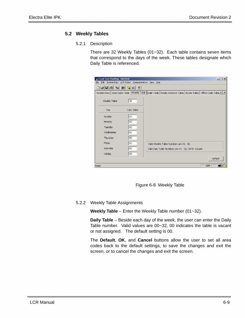
5.2 Weekly Tables ....................................................................................... 6-9
5.2.1 Description .................................................................................6-9
5.2.2 Weekly Table Assignments ........................................................6-9
5.3 Daily Tables ......................................................................................... 6-10
5.3.1 Description ...............................................................................6-10
5.3.2 Daily Table Assignments .........................................................6-10
5.4 Route Advance Tables ........................................................................ 6-11
5.4.1 Description ...............................................................................6-11
5.4.2 Route Advance Table Assignments .........................................6-12
5.5 Route Table ......................................................................................... 6-12
5.5.1 Description ...............................................................................6-12
5.5.2 Route Table Assignments ........................................................6-13
5.6 Office Code Table................................................................................ 6-16
5.6.1 Description ...............................................................................6-16
5.6.2 Office Code Table Assignments ..............................................6-17
5.7 Extra Code Tables ............................................................................... 6-18
5.7.1 Description ...............................................................................6-18
5.7.2 Extra Code Table Assignments ...............................................6-18
5.8 Home NPA Table (Home NPA Code).................................................. 6-19
5.8.1 Description ...............................................................................6-19
Document Revision 2 Electra Elite IPK___________________________________________________________________________________
iv Table of Contents
___________________________________________________________________________________
5.8.2 Home NPA Assignments ..........................................................6-19
5.9 Local Area Code Table ........................................................................ 6-20
5.9.1 Description ...............................................................................6-20
5.9.2 Local Area Code Table Assignments .......................................6-20
5.10 Pre Digit Tables ................................................................................... 6-21
5.10.1 Description ...............................................................................6-21
5.11 Holiday Tables ..................................................................................... 6-22
5.11.1 Description ...............................................................................6-22
5.11.2 Holiday Table Assignments ......................................................6-22
5.12 International / Operator Table .............................................................. 6-23
5.12.1 Description ...............................................................................6-23
5.12.2 International/Operator Call Table Assignments .......................6-23
5.13 OCC Table ........................................................................................... 6-24
5.13.1 Description ...............................................................................6-24
5.13.2 OCC Table Assignments ..........................................................6-24
5.14 Operator Call Time Out Table.............................................................. 6-25
5.14.1 Description ...............................................................................6-25
5.14.2 Operator Call Time Out Table Assignment ..............................6-25
5.15 Extra Add International / Operator Table ............................................. 6-26
5.15.1 Description ...............................................................................6-26
5.15.2 Extra Add International / Operator Table Assignments ............6-26
5.16 Extra Add OCC Table .......................................................................... 6-27
5.16.1 Extra Add OCC Table ..............................................................6-27
5.16.2 Extra Add OCC Table Assignments .........................................6-28
Section 6 Printing .................................................................................................6-29
6.1 Printing LCR Data Tables .................................................................... 6-29
Electra Elite IPK Document Revision 2
Key-Common Channel Interoffice Signaling Manual - v
___________________________________________________________________________________
___________________________________________________________________________________
LCR Manual v
___________________________________________________________________________________
Chapter 7 Error Messages
Section 1 Error Messages ..................................................................................... 7-1
Chapter 8 LCR Flowcharts
Section 1 LCR Flowcharts ..................................................................................... 8-1
1.1 General ..................................................................................................8-1
Chapter 9 LCR Job Specification Worksheets
Section 1 Worksheets ............................................................................................ 9-1
1.1 Area Code Tables (1~4) ......................................................................9-1
1.2 Schedule Tables ................................................................................... 9-3
1.3 Route Advance Tables .......................................................................... 9-7
1.4 Route Tables ........................................................................................ 9-9
1.5 Office Code Tables .............................................................................. 9-14
1.6 Local Area Code Tables ...................................................................... 9-16
1.7 Pre Digit Code Tables.......................................................................... 9-17
1.8 Holiday Tables .................................................................................... 9-18
1.9 International Operator Table ............................................................... 9-19
1.10 OCC Table .......................................................................................... 9-20
1.11 Extra Add International / Operator Table ............................................ 9-21
1.12 Extra Add OCC Table ......................................................................... 9-22
1.13 Operator Call Time Out Table.............................................................. 9-23

Document Revision 2 Electra Elite IPK___________________________________________________________________________________
vi Table of Contents
___________________________________________________________________________________
THIS PAGE INTENTIONALLY LEFT BLANK
LCR Manual vii
___________________________________________________________________________________
___________________________________________________________________________________
LIST OF FIGURES
Figure 1-1 CPUI( )-U( ) ETU ...........................................................................................................1-4
Figure 2-1 Starting LCR ..................................................................................................................2-2
Figure 2-2 Password Screen ..........................................................................................................2-3
Figure 3-1 Direct Connection Example ...........................................................................................3-1
Figure 3-2 Remote Connection (Built-in Modem) Example ............................................................3-2
Figure 3-3 Remote Connection (External Modem) Example ..........................................................3-3
Figure 3-4 LAN/WAN Connection ...................................................................................................3-4
Figure 4-1 Setup and Initialize Screen ............................................................................................4-1
Figure 4-2 Connection Type Screen ...............................................................................................4-2
Figure 4-3 Example of No Connection ............................................................................................4-3
Figure 4-4 Connection Type Screen ...............................................................................................4-4
Figure 4-5 Connection Type Screen ...............................................................................................4-5
Figure 4-6 Host Setup Screen ........................................................................................................4-6
Figure 4-7 IP Connection Setup Screen .........................................................................................4-6
Figure 4-8 Search for Device Screen .............................................................................................4-7
Figure 4-9 Device Search Results Screen ......................................................................................4-7
Figure 4-10 Example of IP Connection Setup ..................................................................................4-8
Figure 4-11 IP Connection Setup .....................................................................................................4-8
Figure 4-12 Successful Configuration Screen ..................................................................................4-9
Figure 4-13 Connect Screen ...........................................................................................................4-10
Figure 4-14 IP Address on Connect Screen ...................................................................................4-11
Figure 5-1 Least Cost Routing Software Screen Samples .............................................................5-2
Figure 5-2 File Menu .......................................................................................................................5-4
Figure 5-3 Edit Menu ......................................................................................................................5-6
Figure 5-4 System Data Menu ........................................................................................................5-7
Document Revision 2 Electra Elite IPK___________________________________________________________________________________
viii List of Figures
___________________________________________________________________________________
Figure 5-5 LCR Tables Menu ..........................................................................................................5-8
Figure 5-6 Communications Menu ................................................................................................5-11
Figure 5-7 Printing Menu ..............................................................................................................5-13
Figure 5-8 View Menu ...................................................................................................................5-14
Figure 5-9 Help Menu ...................................................................................................................5-15
Figure 6-1 Password Screen ..........................................................................................................6-1
Figure 6-2 Change Password Screen .............................................................................................6-2
Figure 6-3 Entry Errors ...................................................................................................................6-3
Figure 6-4 Error Message Display ..................................................................................................6-4
Figure 6-5 LCR System Data Flow (Domestic) ...............................................................................6-5
Figure 6-6 LCR System Data Flow (International/Operator Call) ....................................................6-6
Figure 6-7 Area Code Table ...........................................................................................................6-7
Figure 6-8 Weekly Table .................................................................................................................6-9
Figure 6-9 Daily Table ...................................................................................................................6-10
Figure 6-10 Route Advance Table ..................................................................................................6-11
Figure 6-11 Route Table .................................................................................................................6-13
Figure 6-12 Office Code Table ........................................................................................................6-16
Figure 6-13 Extra Code Table .........................................................................................................6-18
Figure 6-14 Home NPA Table .........................................................................................................6-19
Figure 6-15 Local Area Code Table ................................................................................................6-20
Figure 6-16 Pre Digit Table .............................................................................................................6-21
Figure 6-17 Holiday Table ...............................................................................................................6-22
Figure 6-18 International/Operator Table ........................................................................................6-23
Figure 6-19 OCC Table ...................................................................................................................6-24
Figure 6-20 Operator Call Time Out Table .....................................................................................6-25
Figure 6-21 International / Operator Table ......................................................................................6-26
Figure 6-22 Extra Add OCC Table ..................................................................................................6-27
Figure 6-23 LCR Print Screen .........................................................................................................6-29
Figure 6-24 Report Sample .............................................................................................................6-30
Electra Elite IPK Document Revision 2
Key-Common Channel Interoffice Signaling Manual - ix
___________________________________________________________________________________
___________________________________________________________________________________
LCR Manual ix
___________________________________________________________________________________
Figure 8-1 LCR Flowchart 1 ............................................................................................................8-2
Figure 8-2 LCR Flowchart 2 ............................................................................................................8-3
Figure 8-3 LCR Flowchart 3 ............................................................................................................8-4
Figure 8-4 International / Operator Call Flowchart ..........................................................................8-5
Figure 8-5 OCC Flowchart ..............................................................................................................8-6
Figure 8-6 International / Operator / OCC Continuation Flowchart .................................................8-7
Figure 9-1 Area Code Tables (Description) ....................................................................................9-1
Figure 9-2 Area Code Tables (Worksheet) .....................................................................................9-2
Figure 9-3 Weekly Schedule Tables (Description) .........................................................................9-3
Figure 9-4 Weekly Schedule Tables (Worksheet) ..........................................................................9-4
Figure 9-5 Daily Schedule Tables (Description) .............................................................................9-5
Figure 9-6 Daily Schedule Table (Worksheet) ................................................................................9-6
Figure 9-7 Route Advance Tables (Description) .............................................................................9-7
Figure 9-8 Route Advance Tables (Worksheets) ............................................................................9-8
Figure 9-9 Route Tables (Description) ............................................................................................9-9
Figure 9-10 Route Tables (Worksheets) .........................................................................................9-10
Figure 9-11 Route Tables (Worksheets) .........................................................................................9-11
Figure 9-12 Home NPA and Extra Code Tables (Description) .......................................................9-12
Figure 9-13 Home NPA and Extra Code Tables (Worksheet) ........................................................9-13
Figure 9-14 Office Code Tables (Description) ................................................................................9-14
Figure 9-15 Office Code Tables (Worksheet) .................................................................................9-15

Document Revision 2 Electra Elite IPK___________________________________________________________________________________
x List of Figures
___________________________________________________________________________________
THIS PAGE INTENTIONALLY LEFT BLANK
LCR Manual 1-1
___________________________________________________________________________________
___________________________________________________________________________________
Introduction Chapter 1
SECTION 1 OVERVIEW
The Least Cost Routing (LCR) program is a Windows application that allows the userto easily program and configure the LCR feature of the Electra Elite IPK and ElectraElite 48/192 systems from most any personal computer.
SECTION 2 LCR OVERVIEW
Least Cost Routing (LCR) is used by the system to select the most economical routewhen originating outside calls.
LCR requires the installation of an MIFM-U10 ETU with KMM(1.0)U unit and apersonal computer for programming Least Cost Routing Tables. Refer to Section 2.1Features Added with Software Versions
LCR can select lines for Foreign Exchange (FX), Specialized Common Carrier (SCC),outward Wide Area Telecommunications Service (WATS), Direct Distance Dial (DDD),and Tie lines (TIE).
LCR can be programmed (using various tables) to direct calls through the leastexpensive route based on the number dialed, the time of day, and the day of theweek.
LCR cannot access Common Control Switching Arrangement (CCSA) lines orincoming only lines, such as Direct Inward Dial (DID) or inward WATS lines. LCR canbe used also to route operator, credit card, or international calls. Manually selecting atrunk bypasses LCR.
2.1 Features Added with Software Versions
2.1.1 LCR PC Programming Version
• Version 1.00 -
� Initial Release
1-2 Introduction
___________________________________________________________________________________
___________________________________________________________________________________Document Revision 2 Electra Elite IPK
• Version 2.00 -
� Ability to route Operator/International and OCC calls throughLCR.
� Ability to select Route Advanced Blocks in a Route Table for usein the ISDN-PRI Call-by-Call feature.
• Version 3.00 -
� Ability to add extra code digits to Operator/International and OCCcalls routed through LCR.
• Version 4.00 -
� Added LAN/WAN Communication Method.
� Changed to TAB-based programming screens to look and feelmore like SAT.
2.1.2 MIFM Software
• Version 1.00 -
� Initial Release
• Version 2.00 -
� Ability to route Operator/International and OCC calls throughLCR.
� Ability to select Route Advanced Blocks in a Route Table for usein the ISDN-PRI Call-by-Call feature.
• Version 3.00 -
� Ability to add extra code digits to Operator/ International andOCC calls routed through LCR.
� Ability to analyze the incoming digits from a trunk group to berouted through LCR.
� Ability to select whether or not a station can print to SMDR(MB 4-56).
• Version 4.00 -
� Changed the number of supported Route Advance Blocks from16 to 32 for K-CCIS support.
• Version 5.00 -
� Increased the Caller ID Scrolling Buffer from 10 to 50 per station.
� Added Centralized Billing support for K-CCIS.
Electra Elite IPK Document Revision 2
LCR Manual 1-3
___________________________________________________________________________________
___________________________________________________________________________________
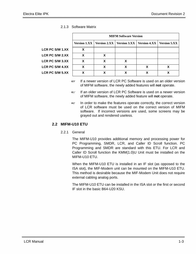
2.1.3 Software Matrix
� If a newer version of LCR PC Software is used on an older versionof MIFM software, the newly added features will not operate.
� If an older version of LCR PC Software is used on a newer versionof MIFM software, the newly added feature will not operate.
� In order to make the features operate correctly, the correct versionof LCR software must be used on the correct version of MIFMsoftware. If incorrect versions are used, some screens may begrayed out and rendered useless.
2.2 MIFM-U10 ETU
2.2.1 General
The MIFM-U10 provides additional memory and processing power forPC Programming, SMDR, LCR, and Caller ID Scroll function. PCProgramming and SMDR are standard with this ETU. For LCR andCaller ID Scroll function the KMM(1.0)U Unit must be installed on theMIFM-U10 ETU.
When the MIFM-U10 ETU is installed in an IF slot (as opposed to theISA slot), the MIF-Modem unit can be mounted on the MIFM-U10 ETU.This method is desirable because the MIF-Modem Unit does not requireexternal cabling analog ports.
The MIFM-U10 ETU can be installed in the ISA slot or the first or secondIF slot in the basic B64-U20 KSU.
MIFM Software Version
Version 1.XX Version 2.XX Version 3.XX Version 4.XX Version 5.XX
LCR PC S/W 1.XX X
LCR PC S/W 2.XX X X
LCR PC S/W 3.XX X X X
LCR PC S/W 4.XX X X X X X
LCR PC S/W 5.XX X X X X X
1-4 Introduction
___________________________________________________________________________________
___________________________________________________________________________________Document Revision 2 Electra Elite IPK
2.3 Programming System for LCR
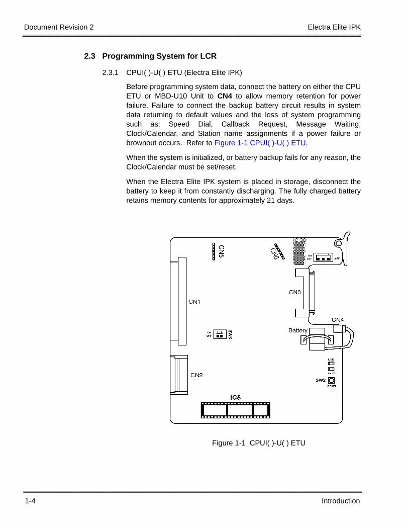
2.3.1 CPUI( )-U( ) ETU (Electra Elite IPK)
Before programming system data, connect the battery on either the CPUETU or MBD-U10 Unit to CN4 to allow memory retention for powerfailure. Failure to connect the backup battery circuit results in systemdata returning to default values and the loss of system programmingsuch as; Speed Dial, Callback Request, Message Waiting,Clock/Calendar, and Station name assignments if a power failure orbrownout occurs. Refer to Figure 1-1 CPUI( )-U( ) ETU.
When the system is initialized, or battery backup fails for any reason, theClock/Calendar must be set/reset.
When the Electra Elite IPK system is placed in storage, disconnect thebattery to keep it from constantly discharging. The fully charged batteryretains memory contents for approximately 21 days.
Figure 1-1 CPUI( )-U( ) ETU
Electra Elite IPK Document Revision 2
LCR Manual 1-5
___________________________________________________________________________________
___________________________________________________________________________________
2.3.2 Programming System Memory Blocks
LCR Class Selection (Memory Block: 4-40)
This Memory Block specifies the LCR class for each station. Thefollowing defines Class/Area Code Table configuration:
Class 0: No LCR
Class 1: Area Code Table 1
Class 2: Area Code Table 2
Class 3: Area Code Table 3
Class 4: Area Code Table 4
LCR Bypass
LCR Bypass is assigned by Class of Service (Memory Block: 1-8-08).Should a station user find it necessary to bypass LCR, the user candirectly access a CO line via a CO line key to bypass LCR.
LCR Recall
LCR Recall is assigned by Class of Service (Memory Block: 1-8-08).LCR Recall is used should a station user find it necessary to generate aFlash to the outside network.
2.4 Numbering Plan Support
Least Cost Routing supports the numbering plan using the following criteria.
� LCR supports the new NANP (Area Code Change N1/0X-NXX). (N = 0~9;X = 2~9)
2.5 System/Station Speed Dial Considerations
System/Station Speed Dial sometimes requires pause(s) between telephonenumbers. These pauses may cause the MIFM-U10 ETU to seize a Least CostRoute because the pauses may be considered digits dialed. Pauses should notbe stored in Speed Dial in systems with the LCR feature.
Pauses should be programmed as part of extra codes in the Extra Code AddTable.

1-6 Introduction
___________________________________________________________________________________
___________________________________________________________________________________Document Revision 2 Electra Elite IPK
THIS PAGE INTENTIONALLY LEFT BLANK
LCR Manual 2-1
___________________________________________________________________________________
___________________________________________________________________________________
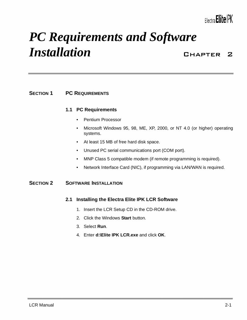
PC Requirements and Software Installation Chapter 2
SECTION 1 PC REQUIREMENTS
1.1 PC Requirements
• Pentium Processor
• Microsoft Windows 95, 98, ME, XP, 2000, or NT 4.0 (or higher) operatingsystems.
• At least 15 MB of free hard disk space.
• Unused PC serial communications port (COM port).
• MNP Class 5 compatible modem (if remote programming is required).
• Network Interface Card (NIC), if programming via LAN/WAN is required.
SECTION 2 SOFTWARE INSTALLATION
2.1 Installing the Electra Elite IPK LCR Software
1. Insert the LCR Setup CD in the CD-ROM drive.
2. Click the Windows Start button.
3. Select Run.
4. Enter d:\Elite IPK LCR.exe and click OK.
2-2 PC Requirements and Software Installation
___________________________________________________________________________________
___________________________________________________________________________________Document Revision 2 Electra Elite IPK
SECTION 3 STARTING THE LCR PROGRAM FROM A PC
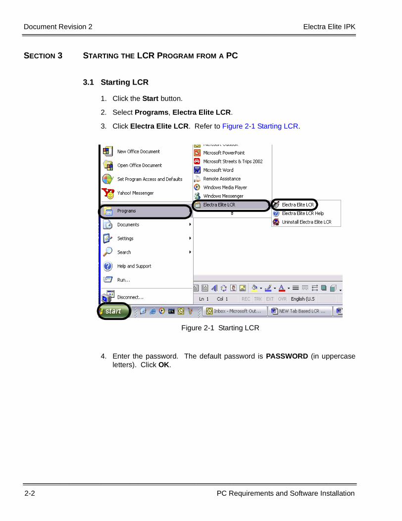
3.1 Starting LCR
1. Click the Start button.
2. Select Programs, Electra Elite LCR.
3. Click Electra Elite LCR. Refer to Figure 2-1 Starting LCR.
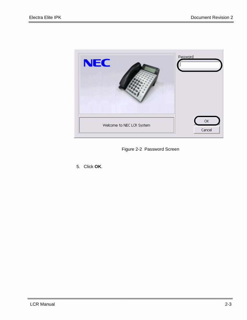
4. Enter the password. The default password is PASSWORD (in uppercaseletters). Click OK.
Figure 2-1 Starting LCR
Electra Elite IPK Document Revision 2
LCR Manual 2-3
___________________________________________________________________________________
___________________________________________________________________________________
5. Click OK.
Figure 2-2 Password Screen
2-4 PC Requirements and Software Installation
___________________________________________________________________________________
___________________________________________________________________________________Document Revision 2 Electra Elite IPK
THIS PAGE INTENTIONALLY LEFT BLANK
LCR Manual 3-1
___________________________________________________________________________________
___________________________________________________________________________________
PC to KSU Communication Methods Chapter 3
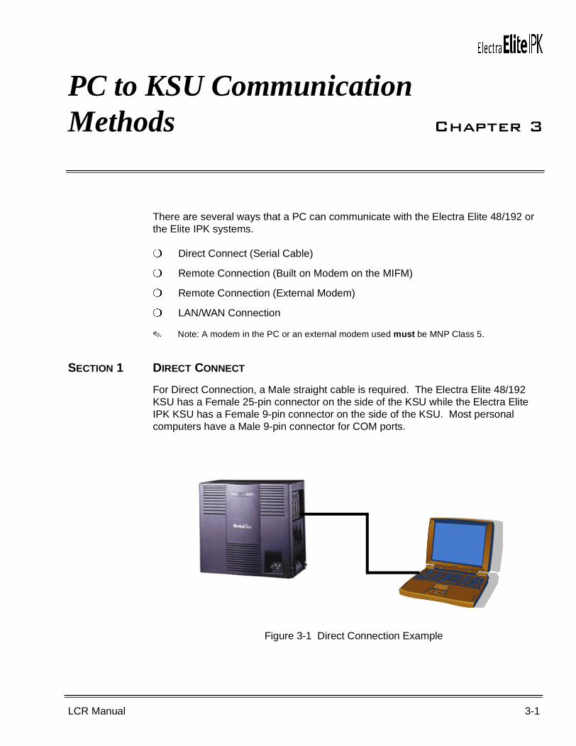
There are several ways that a PC can communicate with the Electra Elite 48/192 or the Elite IPK systems.
� Direct Connect (Serial Cable)
� Remote Connection (Built on Modem on the MIFM)
� Remote Connection (External Modem)
� LAN/WAN Connection
� Note: A modem in the PC or an external modem used must be MNP Class 5.
SECTION 1 DIRECT CONNECT
For Direct Connection, a Male straight cable is required. The Electra Elite 48/192 KSU has a Female 25-pin connector on the side of the KSU while the Electra Elite IPK KSU has a Female 9-pin connector on the side of the KSU. Most personal computers have a Male 9-pin connector for COM ports.
Figure 3-1 Direct Connection Example
3-2 PC to KSU Communication Methods
___________________________________________________________________________________
___________________________________________________________________________________Document Revision 2 Electra Elite IPK
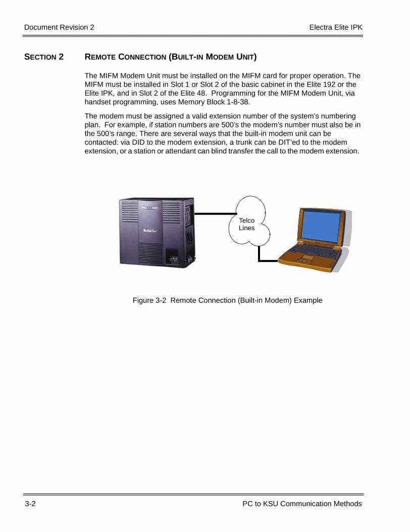
SECTION 2 REMOTE CONNECTION (BUILT-IN MODEM UNIT)
The MIFM Modem Unit must be installed on the MIFM card for proper operation. The MIFM must be installed in Slot 1 or Slot 2 of the basic cabinet in the Elite 192 or the Elite IPK, and in Slot 2 of the Elite 48. Programming for the MIFM Modem Unit, via handset programming, uses Memory Block 1-8-38.
The modem must be assigned a valid extension number of the system’s numbering plan. For example, if station numbers are 500’s the modem’s number must also be in the 500’s range. There are several ways that the built-in modem unit can be contacted: via DID to the modem extension, a trunk can be DIT’ed to the modem extension, or a station or attendant can blind transfer the call to the modem extension.
Figure 3-2 Remote Connection (Built-in Modem) Example
TelcoLines
Electra Elite IPK Document Revision 2
LCR Manual 3-3
___________________________________________________________________________________
__________________________________________________________________________________
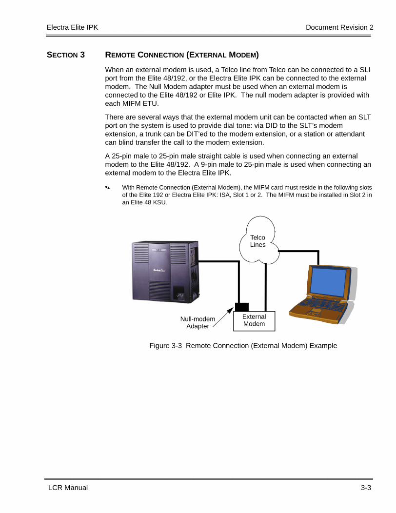
SECTION 3 REMOTE CONNECTION (EXTERNAL MODEM)
When an external modem is used, a Telco line from Telco can be connected to a SLI port from the Elite 48/192, or the Electra Elite IPK can be connected to the external modem. The Null Modem adapter must be used when an external modem is connected to the Elite 48/192 or Elite IPK. The null modem adapter is provided with each MIFM ETU.
There are several ways that the external modem unit can be contacted when an SLT port on the system is used to provide dial tone: via DID to the SLT’s modem extension, a trunk can be DIT’ed to the modem extension, or a station or attendant can blind transfer the call to the modem extension.
A 25-pin male to 25-pin male straight cable is used when connecting an external modem to the Elite 48/192. A 9-pin male to 25-pin male is used when connecting an external modem to the Electra Elite IPK.
� With Remote Connection (External Modem), the MIFM card must reside in the following slots of the Elite 192 or Electra Elite IPK: ISA, Slot 1 or 2. The MIFM must be installed in Slot 2 in an Elite 48 KSU.
Figure 3-3 Remote Connection (External Modem) Example
TelcoLines
External Modem
Null-modem Adapter
3-4 PC to KSU Communication Methods
___________________________________________________________________________________
___________________________________________________________________________________Document Revision 2 Electra Elite IPK
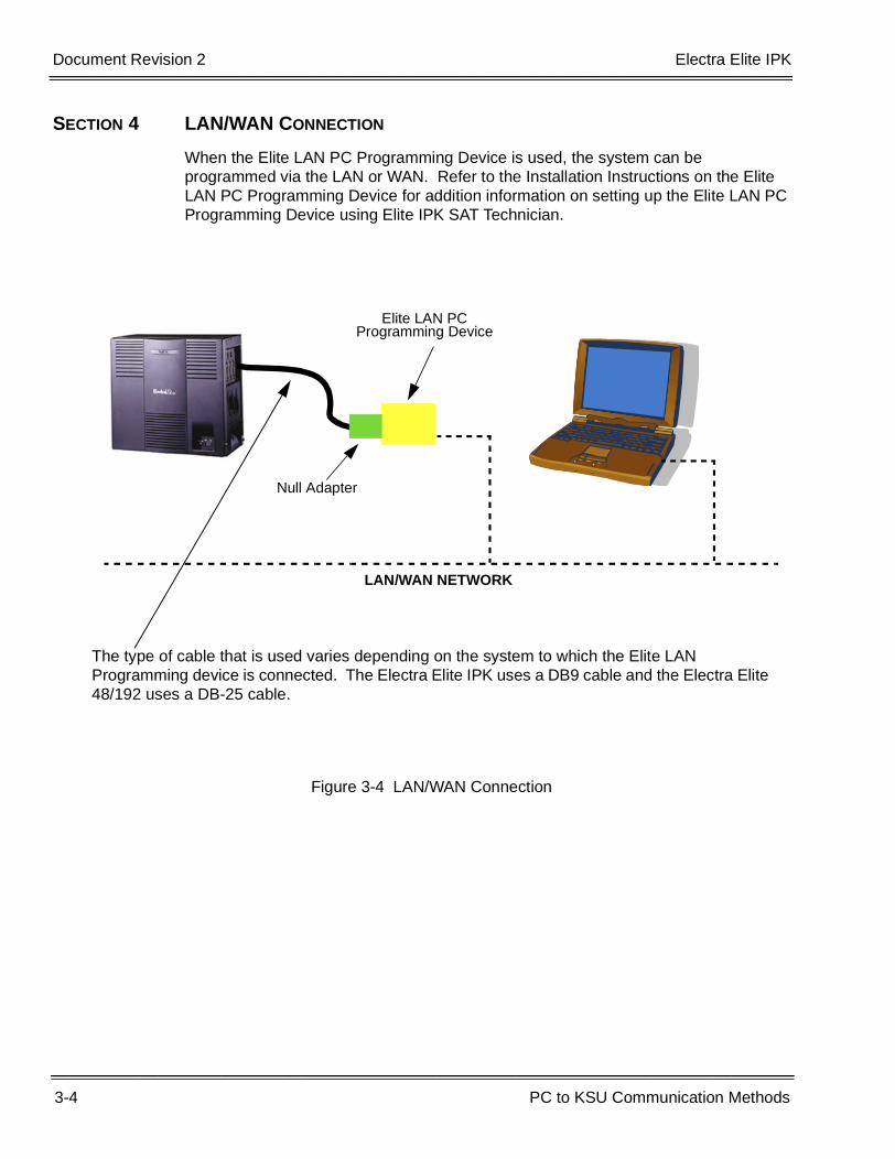
SECTION 4 LAN/WAN CONNECTION
When the Elite LAN PC Programming Device is used, the system can be programmed via the LAN or WAN. Refer to the Installation Instructions on the Elite LAN PC Programming Device for addition information on setting up the Elite LAN PC Programming Device using Elite IPK SAT Technician.
Figure 3-4 LAN/WAN Connection
Null Adapter
Elite LAN PCProgramming Device
LAN/WAN NETWORK
The type of cable that is used varies depending on the system to which the Elite LAN Programming device is connected. The Electra Elite IPK uses a DB9 cable and the Electra Elite 48/192 uses a DB-25 cable.
LCR Manual 4-1
___________________________________________________________________________________
___________________________________________________________________________________
Configuring the Communication Methods Chapter 4
SECTION 1 DIRECT CONNECTION (CONFIGURATION)
When configuring the communication for direct connection, the COM Port speed for COM 1 of the KSU must match the COM Port speed of the PC. For example, if the KSU is set for 38.4K bps then LCR must also be set for 38.4K bps. To set the COM port speed for COM 1 of the KSU, use Memory Blocks 1-8-35 and 1-8-36.
1.1 Setting LCR for Direct Connection
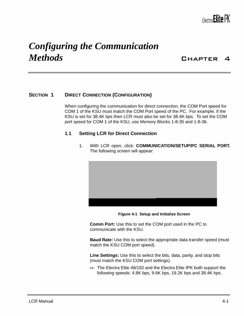
1. With LCR open, click: COMMUNICATION/SETUP/PC SERIAL PORT.The following screen will appear:
Comm Port: Use this to set the COM port used in the PC to communicate with the KSU.
Baud Rate: Use this to select the appropriate data transfer speed (must match the KSU COM port speed).
Line Settings: Use this to select the bits, data, parity, and stop bits (must match the KSU COM port settings).
� The Electra Elite 48/192 and the Electra Elite IPK both support the following speeds: 4.8K bps, 9.6K bps, 19.2K bps and 38.4K bps.
Figure 4-1 Setup and Initialize Screen
4-2 Configuring the Communication Methods
___________________________________________________________________________________
___________________________________________________________________________________Document Revision 2 Electra Elite IPK
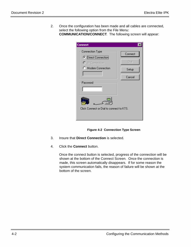
2. Once the configuration has been made and all cables are connected, select the following option from the File Menu: COMMUNICATION/CONNECT. The following screen will appear:
3. Insure that Direct Connection is selected.
4. Click the Connect button.
Once the connect button is selected, progress of the connection will be shown at the bottom of the Connect Screen. Once the connection is made, this screen automatically disappears. If for some reason the system communication fails, the reason of failure will be shown at the bottom of the screen.
Figure 4-2 Connection Type Screen
Electra Elite IPK Document Revision 2
LCR Manual 4-3
___________________________________________________________________________________
___________________________________________________________________________________
5. Once communication has been established, proceed to downloading or uploading the system data.
SECTION 2 REMOTE CONNECTION (VIA BUILT-IN MODEM UNIT CONFIGURATION)
When configuring the system for remote connection with a built-in modem unit, the MIFM with Modem Unit must be located in Slot 1 or 2 of the basic cabinet of the Electra Elite 192/Electra Elite IPK, and in the Slot 2 of the Electra Elite 48. The PC must have a working MNP Class 5 Modem. The maximum speed of data transfer rate for the built-in modem is 19.2K bps.
The modem extension must be assigned to the system before communication can be established. To assign the modem extension, use Memory Block 1-8-38. The number assigned here must comply with the system’s current numbering plan. There are several ways of getting a modem call to the built-in modem: by DID calls, DIT’ed calls, or by Blind Transfer by the Attendant or Station.
� If the modem extension is dialed internally, the modem will not answer.
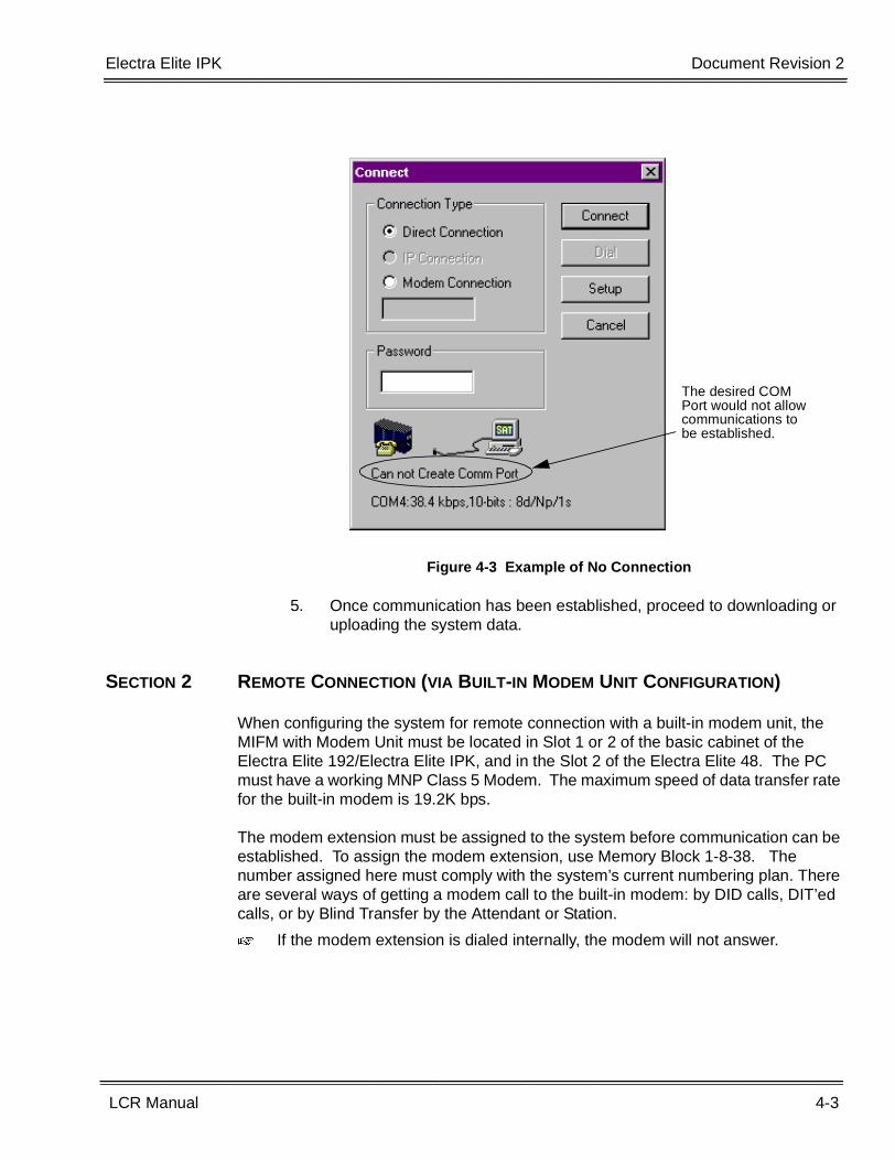
Figure 4-3 Example of No Connection
The desired COM Port would not allow communications to be established.
4-4 Configuring the Communication Methods
___________________________________________________________________________________
___________________________________________________________________________________Document Revision 2 Electra Elite IPK
2.1 Configuring LCR to Dial Remotely
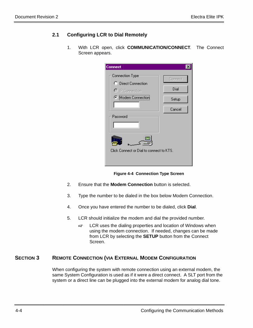
1. With LCR open, click COMMUNICATION/CONNECT. The ConnectScreen appears.
2. Ensure that the Modem Connection button is selected.
3. Type the number to be dialed in the box below Modem Connection.
4. Once you have entered the number to be dialed, click Dial.
5. LCR should initialize the modem and dial the provided number.
� LCR uses the dialing properties and location of Windows when using the modem connection. If needed, changes can be made from LCR by selecting the SETUP button from the Connect Screen.
SECTION 3 REMOTE CONNECTION (VIA EXTERNAL MODEM CONFIGURATION
When configuring the system with remote connection using an external modem, the same System Configuration is used as if it were a direct connect. A SLT port from the system or a direct line can be plugged into the external modem for analog dial tone.
Figure 4-4 Connection Type Screen
Electra Elite IPK Document Revision 2
LCR Manual 4-5
___________________________________________________________________________________
___________________________________________________________________________________
Refer to Section 2 Remote Connection (via Built-in Modem Unit Configuration) for configuring LCR to dial remotely.
SECTION 4 LAN/WAN CONNECTION (CONFIGURATION)
When the LAN/WAN configuration is used, the Elite LAN PC Programming Device must be installed. For detailed information on how to configure the Elite LAN PC Programming Device, refer to the Installation for Elite LAN PC Programming Instructions document.
4.1 Configuring LCR to Communicate via LAN/WAN
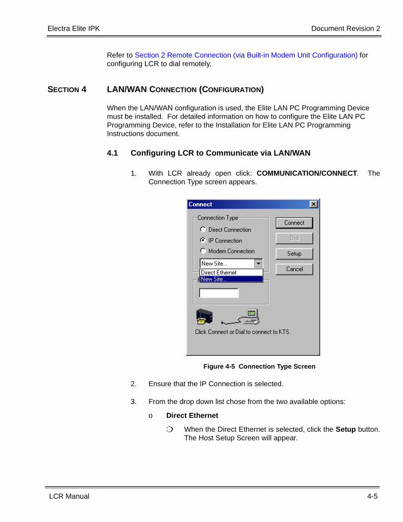
1. With LCR already open click: COMMUNICATION/CONNECT. TheConnection Type screen appears.
2. Ensure that the IP Connection is selected.
3. From the drop down list chose from the two available options:
o Direct Ethernet
� When the Direct Ethernet is selected, click the Setup button.The Host Setup Screen will appear.
Figure 4-5 Connection Type Screen
4-6 Configuring the Communication Methods
___________________________________________________________________________________
___________________________________________________________________________________Document Revision 2 Electra Elite IPK
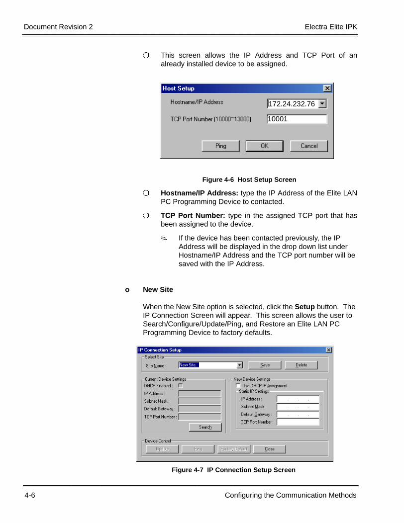
� This screen allows the IP Address and TCP Port of analready installed device to be assigned.
� Hostname/IP Address: type the IP Address of the Elite LANPC Programming Device to contacted.
� TCP Port Number: type in the assigned TCP port that hasbeen assigned to the device.
� If the device has been contacted previously, the IP Address will be displayed in the drop down list under Hostname/IP Address and the TCP port number will be saved with the IP Address.
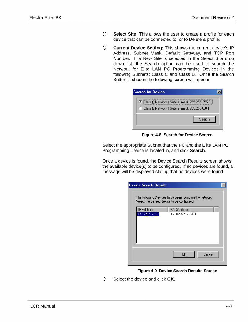
o New Site
When the New Site option is selected, click the Setup button. The IP Connection Screen will appear. This screen allows the user to Search/Configure/Update/Ping, and Restore an Elite LAN PC Programming Device to factory defaults.
Figure 4-6 Host Setup Screen
Figure 4-7 IP Connection Setup Screen
172.24.232.76
10001
Electra Elite IPK Document Revision 2
LCR Manual 4-7
___________________________________________________________________________________
___________________________________________________________________________________
� Select Site: This allows the user to create a profile for eachdevice that can be connected to, or to Delete a profile.
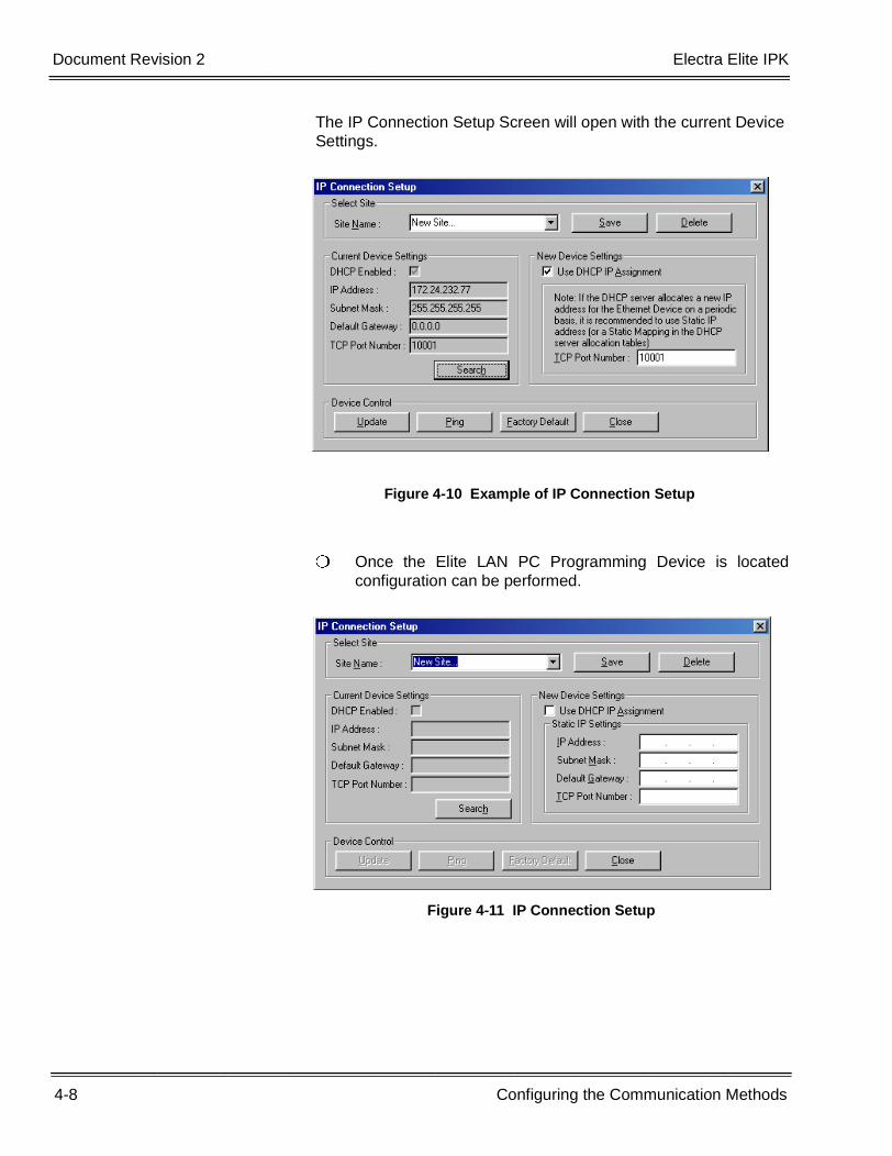
� Current Device Setting: This shows the current device’s IPAddress, Subnet Mask, Default Gateway, and TCP PortNumber. If a New Site is selected in the Select Site dropdown list, the Search option can be used to search theNetwork for Elite LAN PC Programming Devices in thefollowing Subnets: Class C and Class B. Once the SearchButton is chosen the following screen will appear.
Select the appropriate Subnet that the PC and the Elite LAN PC Programming Device is located in, and click Search.
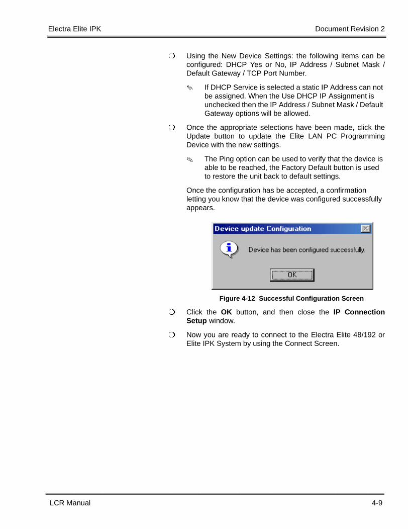
Once a device is found, the Device Search Results screen shows the available device(s) to be configured. If no devices are found, a message will be displayed stating that no devices were found.
� Select the device and click OK.
Figure 4-8 Search for Device Screen
Figure 4-9 Device Search Results Screen
4-8 Configuring the Communication Methods
___________________________________________________________________________________
___________________________________________________________________________________Document Revision 2 Electra Elite IPK
The IP Connection Setup Screen will open with the current Device Settings.
� Once the Elite LAN PC Programming Device is locatedconfiguration can be performed.
Figure 4-10 Example of IP Connection Setup
Figure 4-11 IP Connection Setup
Electra Elite IPK Document Revision 2
LCR Manual 4-9
___________________________________________________________________________________
___________________________________________________________________________________
� Using the New Device Settings: the following items can beconfigured: DHCP Yes or No, IP Address / Subnet Mask /Default Gateway / TCP Port Number.
� If DHCP Service is selected a static IP Address can not be assigned. When the Use DHCP IP Assignment is unchecked then the IP Address / Subnet Mask / Default Gateway options will be allowed.
� Once the appropriate selections have been made, click theUpdate button to update the Elite LAN PC ProgrammingDevice with the new settings.
� The Ping option can be used to verify that the device is able to be reached, the Factory Default button is used to restore the unit back to default settings.
Once the configuration has be accepted, a confirmation letting you know that the device was configured successfully appears.
� Click the OK button, and then close the IP ConnectionSetup window.
� Now you are ready to connect to the Electra Elite 48/192 orElite IPK System by using the Connect Screen.
Figure 4-12 Successful Configuration Screen
4-10 Configuring the Communication Methods
___________________________________________________________________________________
___________________________________________________________________________________Document Revision 2 Electra Elite IPK
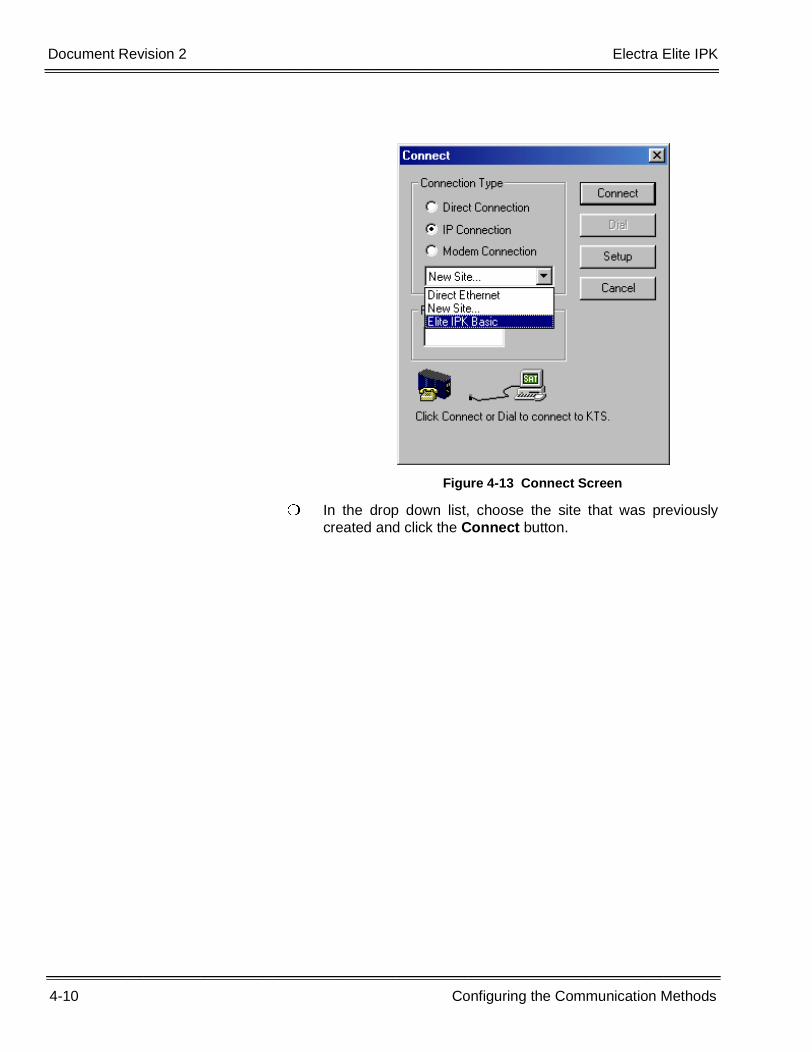
� In the drop down list, choose the site that was previouslycreated and click the Connect button.
Figure 4-13 Connect Screen
Electra Elite IPK Document Revision 2
LCR Manual 4-11
___________________________________________________________________________________
___________________________________________________________________________________
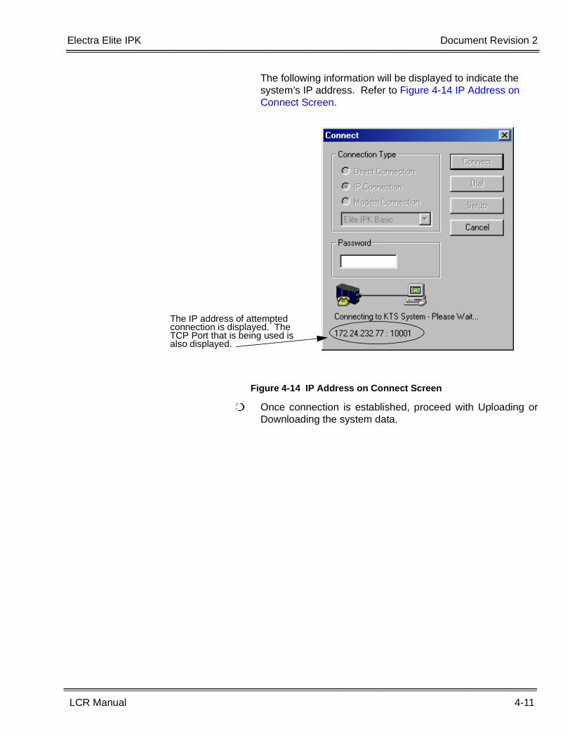
The following information will be displayed to indicate the system’s IP address. Refer to Figure 4-14 IP Address on Connect Screen.
� Once connection is established, proceed with Uploading orDownloading the system data.
Figure 4-14 IP Address on Connect Screen
The IP address of attempted connection is displayed. The TCP Port that is being used is also displayed.
4-12 Configuring the Communication Methods
___________________________________________________________________________________
___________________________________________________________________________________Document Revision 2 Electra Elite IPK
THIS PAGE INTENTIONALLY LEFT BLANK
LCR Manual 5-1
___________________________________________________________________________________
___________________________________________________________________________________
LCR Program Menus Chapter 5
SECTION 1 GENERAL INFORMATION
This chapter provides detailed information for programming using the Least CostRouting (LCR) software.
SECTION 2 LCR PROGRAM SCREENS
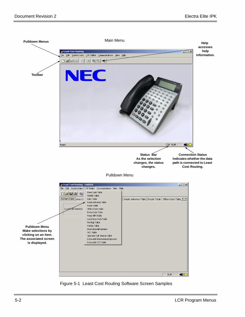
Main Menu
When the LCR software program is launched, the Main Menu screen is displayed.This screen allows the user to access the options used to program Least CostRouting. Figure 5-1 Least Cost Routing Software Screen Samples shows the menuand describes the layout.
Pulldown Menu
Pulldown menus are available for each function involved in programming Least CostRouting. To access the data associated with the function, click on the function nameon the Main Menu. Some options on the initial pulldown menu offer severalselections. An arrow to the right of the option name indicates additional selectionsare available. Refer to Figure 5-1 Least Cost Routing Software Screen Samples foran example of a Pulldown Menu.
5-2 LCR Program Menus
___________________________________________________________________________________
___________________________________________________________________________________Document Revision 2 Electra Elite IPK
Figure 5-1 Least Cost Routing Software Screen Samples
Pulldown Menus
Toolbar
Status BarAs the selection
changes, the status changes.
Helpaccesses
help information.
Pulldown MenuMake selections by clicking on an item.
The associated screen is displayed.
Pulldown Menu
Main Menu
Connection StatusIndicates whether the data path is connected to Least
Cost Routing.
Electra Elite IPK Document Revision 2
LCR Manual 5-3
___________________________________________________________________________________
__________________________________________________________________________________
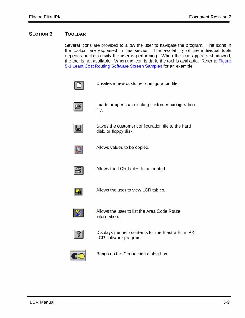
SECTION 3 TOOLBAR
Several icons are provided to allow the user to navigate the program. The icons inthe toolbar are explained in this section The availability of the individual toolsdepends on the activity the user is performing. When the icon appears shadowed,the tool is not available. When the icon is dark, the tool is available. Refer to Figure5-1 Least Cost Routing Software Screen Samples for an example.
Creates a new customer configuration file.
Loads or opens an existing customer configuration file.
Saves the customer configuration file to the hard disk, or floppy disk.
Allows values to be copied.
Allows the LCR tables to be printed.
Allows the user to view LCR tables.
Allows the user to list the Area Code Route information.
Displays the help contents for the Electra Elite IPK LCR software program.
Brings up the Connection dialog box.

5-4 LCR Program Menus
___________________________________________________________________________________
___________________________________________________________________________________Document Revision 2 Electra Elite IPK
SECTION 4 LCR PULLDOWN MENUS
This section explains each available LCR software pulldown menu.
File
The File pulldown menu provides options for basic file management.
New
Creates a new customer file.
Open
Loads an existing customer file.
Save
Saves the customer file. This option is only available when a customer file is open.
Figure 5-2 File Menu
Electra Elite IPK Document Revision 2
LCR Manual 5-5
___________________________________________________________________________________
__________________________________________________________________________________
Save As
The Save As menu saves a customer file using a new name. This option is onlyavailable when a customer file is open.
Change Password
Allows the user to change the LCR password.
Close
Closes the current customer file. This option is only available when a customer file isopen.
Exit
Exits the LCR software. If changes are not saved, the technician is prompted to savethe changes before the program shuts down.
5-6 LCR Program Menus
___________________________________________________________________________________
___________________________________________________________________________________Document Revision 2 Electra Elite IPK
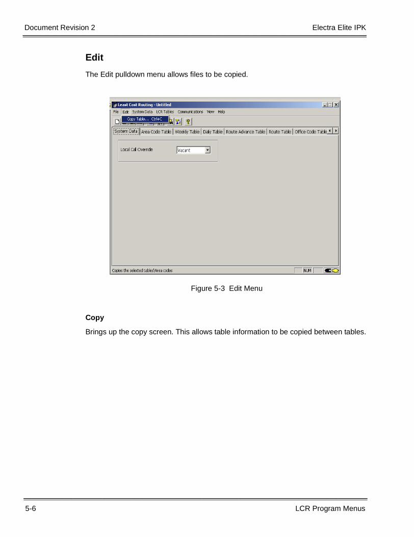
Edit
The Edit pulldown menu allows files to be copied.
Copy
Brings up the copy screen. This allows table information to be copied between tables.
Figure 5-3 Edit Menu
Electra Elite IPK Document Revision 2
LCR Manual 5-7
___________________________________________________________________________________
__________________________________________________________________________________
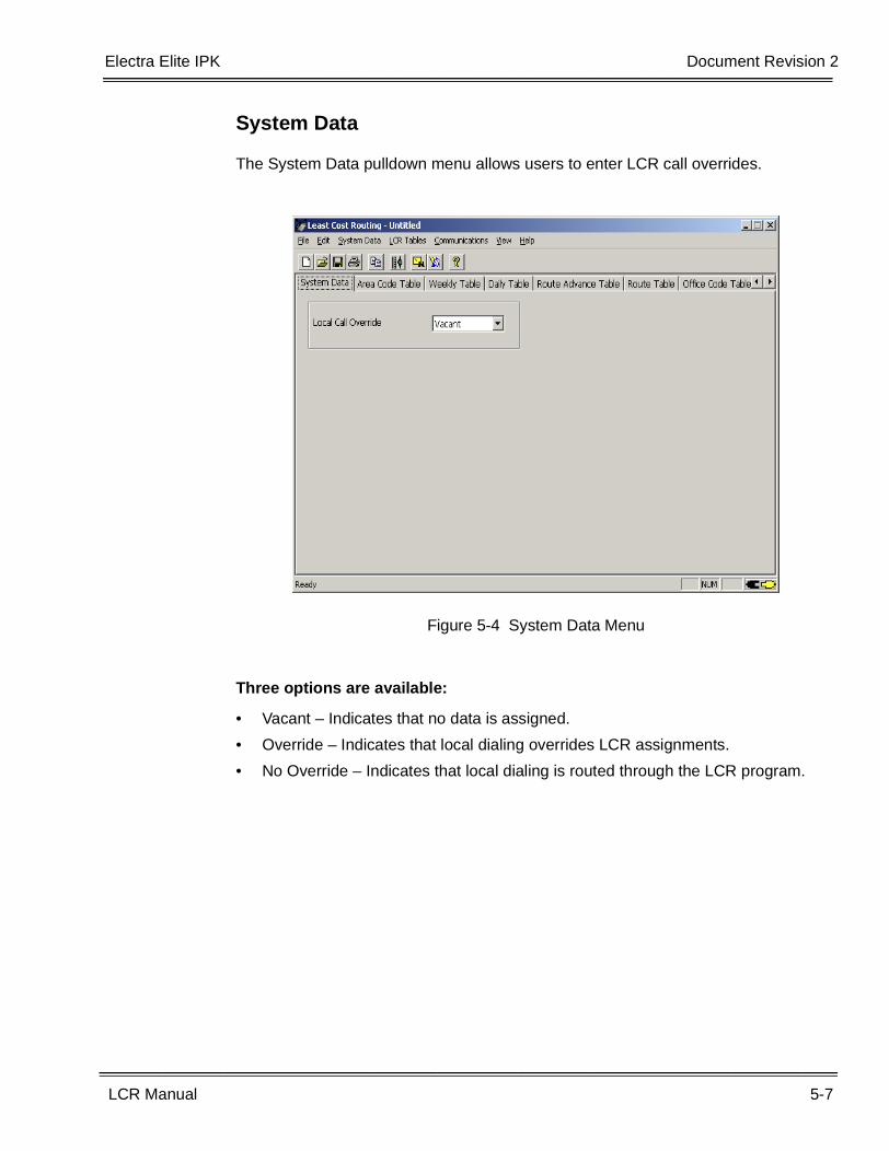
System Data
The System Data pulldown menu allows users to enter LCR call overrides.
Three options are available:
• Vacant – Indicates that no data is assigned.
• Override – Indicates that local dialing overrides LCR assignments.
• No Override – Indicates that local dialing is routed through the LCR program.
Figure 5-4 System Data Menu
5-8 LCR Program Menus
___________________________________________________________________________________
___________________________________________________________________________________Document Revision 2 Electra Elite IPK
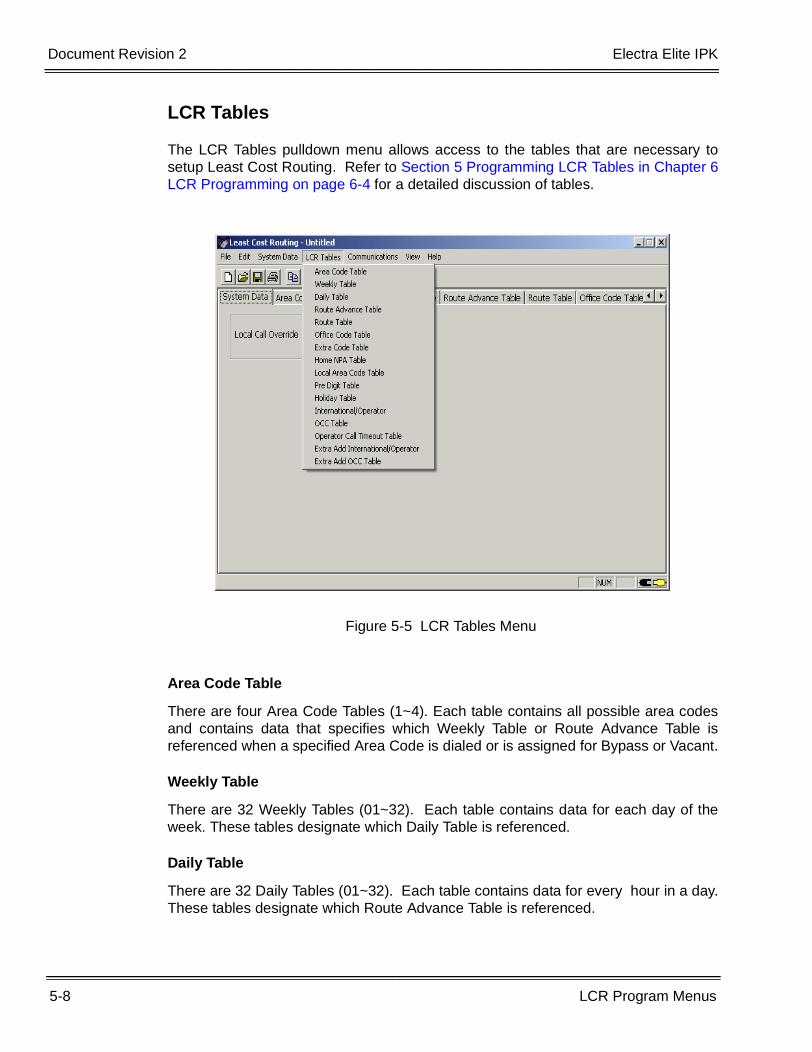
LCR Tables
The LCR Tables pulldown menu allows access to the tables that are necessary tosetup Least Cost Routing. Refer to Section 5 Programming LCR Tables in Chapter 6LCR Programming on page 6-4 for a detailed discussion of tables.
Area Code Table
There are four Area Code Tables (1~4). Each table contains all possible area codesand contains data that specifies which Weekly Table or Route Advance Table isreferenced when a specified Area Code is dialed or is assigned for Bypass or Vacant.
Weekly Table
There are 32 Weekly Tables (01~32). Each table contains data for each day of theweek. These tables designate which Daily Table is referenced.
Daily Table
There are 32 Daily Tables (01~32). Each table contains data for every hour in a day.These tables designate which Route Advance Table is referenced.
Figure 5-5 LCR Tables Menu
Electra Elite IPK Document Revision 2
LCR Manual 5-9
___________________________________________________________________________________
__________________________________________________________________________________
Route Advance Table
There are 64 Route Advance Tables (01~64). Each table can contain eight entries(1~8) that correspond to the Route Tables that are accessed [in priority order (1~8)].The LCR subsystem attempts to seize routes based on this order, starting with thefirst. If this route is unavailable, the second route is accessed. If no route is available,or if a lower priority route is not specified, the user is denied access to the outsidetrunks. The same Route Table can be assigned to different priority levels in the RouteAdvance Table.
Route Table
There are 256 Route Tables (001~256). The specified Route Table determines whichTrunk Group is selected and the digits to be dialed to complete a call routed usingLCR.
Office Code Table
There are 64 Office Code Tables (01~64). Each Office Code Table contains all thepossible Office Codes and a box that can be checked for each Office Code. Themeaning of the setting of each flag bit depends on whether the Office Code Table isreferenced by the Prefix Add/Check or Service Area Check parameters of a specifiedRoute Table.
Extra Code Table
There are 16 Extra Code Tables (01~16). Each Extra Code Table can contain amaximum of 32 digits.
Home NPA Table
There is one Home NPA Table. This table is used to enter the Area Code where thesystem resides. This assignment is very important and MUST be made when localcalls (calls dialed without an Area Code) are to be routed through LCR.
Local Area Code Table
A maximum of 16 local area codes can be assigned in this table. If a 1+ area codenumber is dialed or if only the area code is dialed, the area codes entered in this tableare routed through the LCR Area Code Table.
Pre Digit Table
This table defines any central office feature codes (such as Caller ID displaysuppression #64) that are dialed by a user. When these codes along with thetelephone number are dialed by the user, LCR recognizes the numbers as pre-digitcodes based on the entry in the Pre Digit Table. While LCR is determining callrouting, these codes are stored. Before LCR redials the number, stored feature codesare inserted in front of the telephone number.
5-10 LCR Program Menus
___________________________________________________________________________________
___________________________________________________________________________________Document Revision 2 Electra Elite IPK
Holiday Table
On selected days of the year, LCR can route all calls based on a holiday schedule.The holiday table applies to all area codes on the day in question. LCR routes arethen assigned based on time of day.
International / Operator Table
This table allows LCR to route calls to international or local operators via differentTrunk Group or Route Advance Block priorities. This table applies to all internationaloperator calls that are not set to bypass for the matching LCR class.
OCC Table
This table allows LCR to route calls dialed with OCC codes via different Trunk Groupor Route Advance Block priorities. This table applies to all calls that are dialed with anOCC Code LCR class. Each table has the ability to route 16 different OCC codes.
Operator Call Time out Table
This table sets a timer (in seconds) that determines how much time the caller has todial valid operator call access codes before the call times-out and starts processing.
Extra Add International / Operator Table
This table allows the same 16 Extra Code Tables (01~16) that is shared with thenormal LCR. Each Extra Code Table can contain a maximum of 32 digits. The ExtraCode Table adds extra digits that are inserted before the number dialed by the user.This option can also be used to access a PBX line where it is necessary to dial a PBXAccess Code or tandem access to a remote system line through a TIE line.
Extra Add OCC Table
This table allows the same 16 Extra Code Tables (01~16) that is shared with thenormal LCR. Each Extra Code Table can contain a maximum of 32 digits. The ExtraCode Table adds extra digits that are inserted before the number dialed by the user.This option can also be used to access a PBX line where it is necessary to dial a PBXAccess Code or tandem access to a remote system line through a TIE line.
Electra Elite IPK Document Revision 2
LCR Manual 5-11
___________________________________________________________________________________
__________________________________________________________________________________
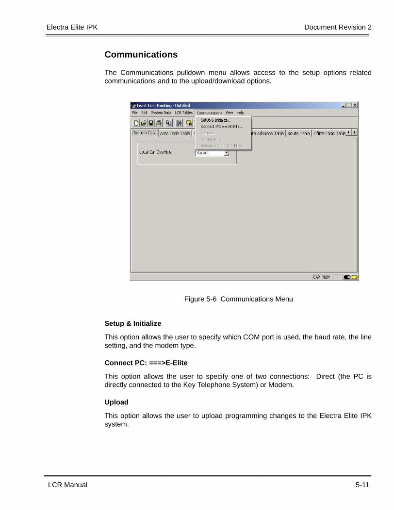
Communications
The Communications pulldown menu allows access to the setup options relatedcommunications and to the upload/download options.
Setup & Initialize
This option allows the user to specify which COM port is used, the baud rate, the linesetting, and the modem type.
Connect PC: ===>E-Elite
This option allows the user to specify one of two connections: Direct (the PC isdirectly connected to the Key Telephone System) or Modem.
Upload
This option allows the user to upload programming changes to the Electra Elite IPKsystem.
Figure 5-6 Communications Menu
5-12 LCR Program Menus
___________________________________________________________________________________
___________________________________________________________________________________Document Revision 2 Electra Elite IPK
Download
This option allows the user to download the current LCR configuration.
Release PC == X E-Elite
This option allows the user to disconnect the PC that was used to program LCR fromthe Electra Elite IPK system.
Electra Elite IPK Document Revision 2
LCR Manual 5-13
___________________________________________________________________________________
__________________________________________________________________________________
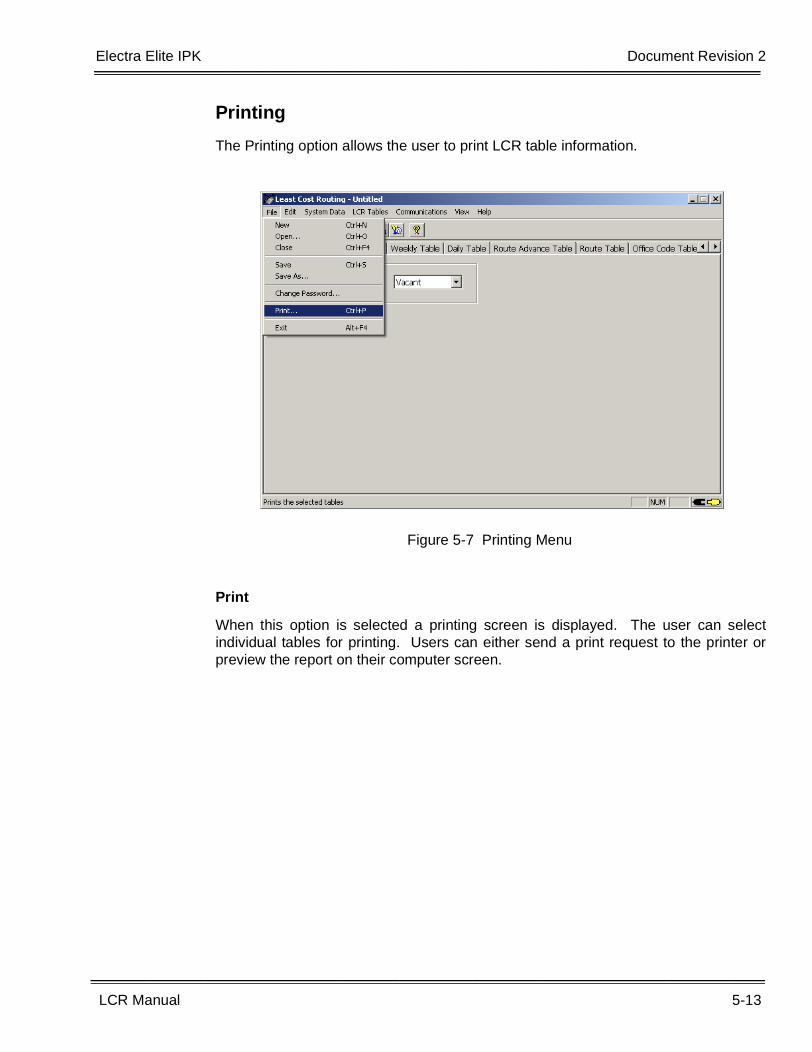
Printing
The Printing option allows the user to print LCR table information.
When this option is selected a printing screen is displayed. The user can selectindividual tables for printing. Users can either send a print request to the printer orpreview the report on their computer screen.
Figure 5-7 Printing Menu
5-14 LCR Program Menus
___________________________________________________________________________________
___________________________________________________________________________________Document Revision 2 Electra Elite IPK
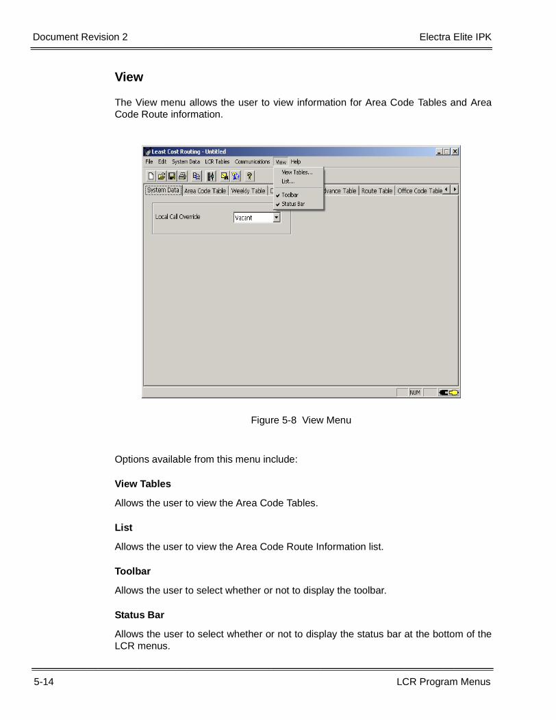
View
The View menu allows the user to view information for Area Code Tables and AreaCode Route information.
Options available from this menu include:
View Tables
Allows the user to view the Area Code Tables.
List
Allows the user to view the Area Code Route Information list.
Toolbar
Allows the user to select whether or not to display the toolbar.
Status Bar
Allows the user to select whether or not to display the status bar at the bottom of theLCR menus.
Figure 5-8 View Menu
Electra Elite IPK Document Revision 2
LCR Manual 5-15
___________________________________________________________________________________
__________________________________________________________________________________
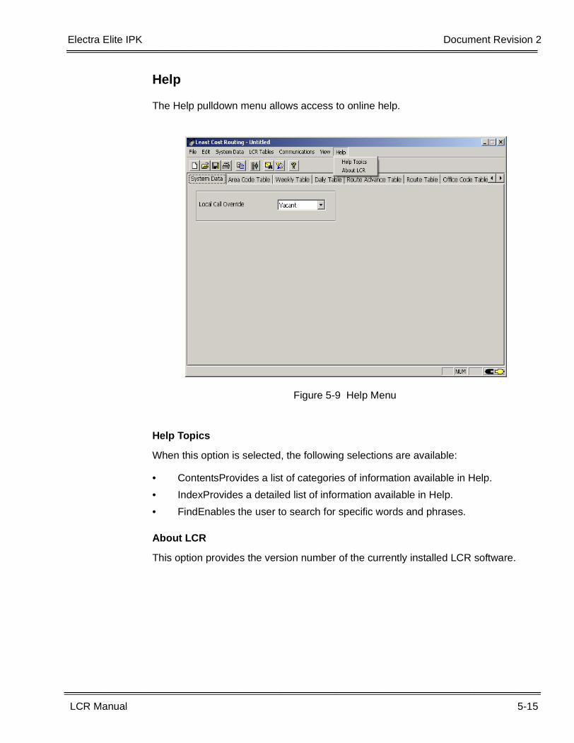
Help
The Help pulldown menu allows access to online help.
Help Topics
When this option is selected, the following selections are available:
• ContentsProvides a list of categories of information available in Help.
• IndexProvides a detailed list of information available in Help.
• FindEnables the user to search for specific words and phrases.
About LCR
This option provides the version number of the currently installed LCR software.
Figure 5-9 Help Menu
5-16 LCR Program Menus
___________________________________________________________________________________
___________________________________________________________________________________Document Revision 2 Electra Elite IPK
THIS PAGE INTENTIONALLY LEFT BLANK
LCR Manual 6-1
___________________________________________________________________________________
___________________________________________________________________________________
LCR Programming Chapter 6
SECTION 1 STARTING LCR PROGRAM
1.1 Starting from the Windows Desktop Screen
To run LCR from Windows:
1. Click Start from the Windows toolbar.
2. Select Programs, Electra Elite IPK LCR.
3. Click on Electra Elite IPK LCR.
4. Enter the password. The default password is PASSWORD (use alluppercase letters).
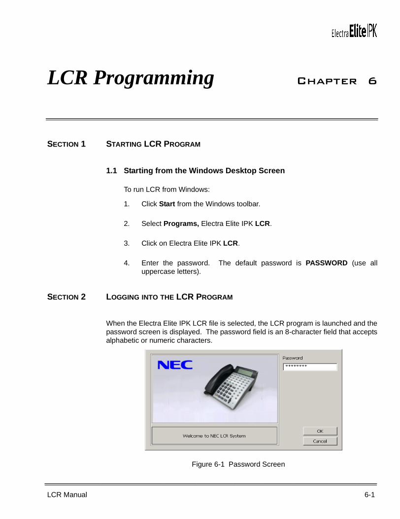
SECTION 2 LOGGING INTO THE LCR PROGRAM
When the Electra Elite IPK LCR file is selected, the LCR program is launched and thepassword screen is displayed. The password field is an 8-character field that acceptsalphabetic or numeric characters.
Figure 6-1 Password Screen
6-2 LCR Programming
___________________________________________________________________________________
___________________________________________________________________________________Document Revision 2 Electra Elite IPK
2.1 Entering the Password for the First Time
The default login code is PASSWORD (uppercase). After the password isentered, select OK. Refer to Figure 6-1 Password Screen.
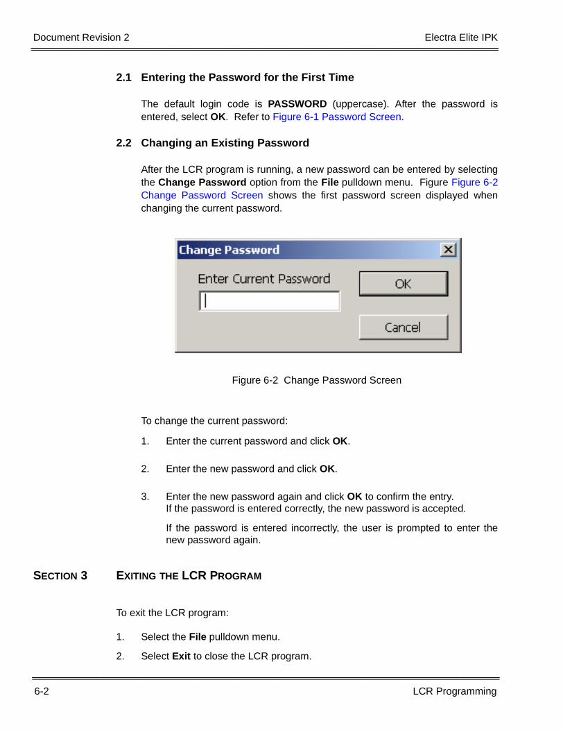
2.2 Changing an Existing Password
After the LCR program is running, a new password can be entered by selectingthe Change Password option from the File pulldown menu. Figure Figure 6-2Change Password Screen shows the first password screen displayed whenchanging the current password.
To change the current password:
1. Enter the current password and click OK.
2. Enter the new password and click OK.
3. Enter the new password again and click OK to confirm the entry.If the password is entered correctly, the new password is accepted.
If the password is entered incorrectly, the user is prompted to enter thenew password again.
SECTION 3 EXITING THE LCR PROGRAM
To exit the LCR program:
1. Select the File pulldown menu.
2. Select Exit to close the LCR program.
Figure 6-2 Change Password Screen
Electra Elite IPK Document Revision 2
LCR Manual 6-3
___________________________________________________________________________________
___________________________________________________________________________________
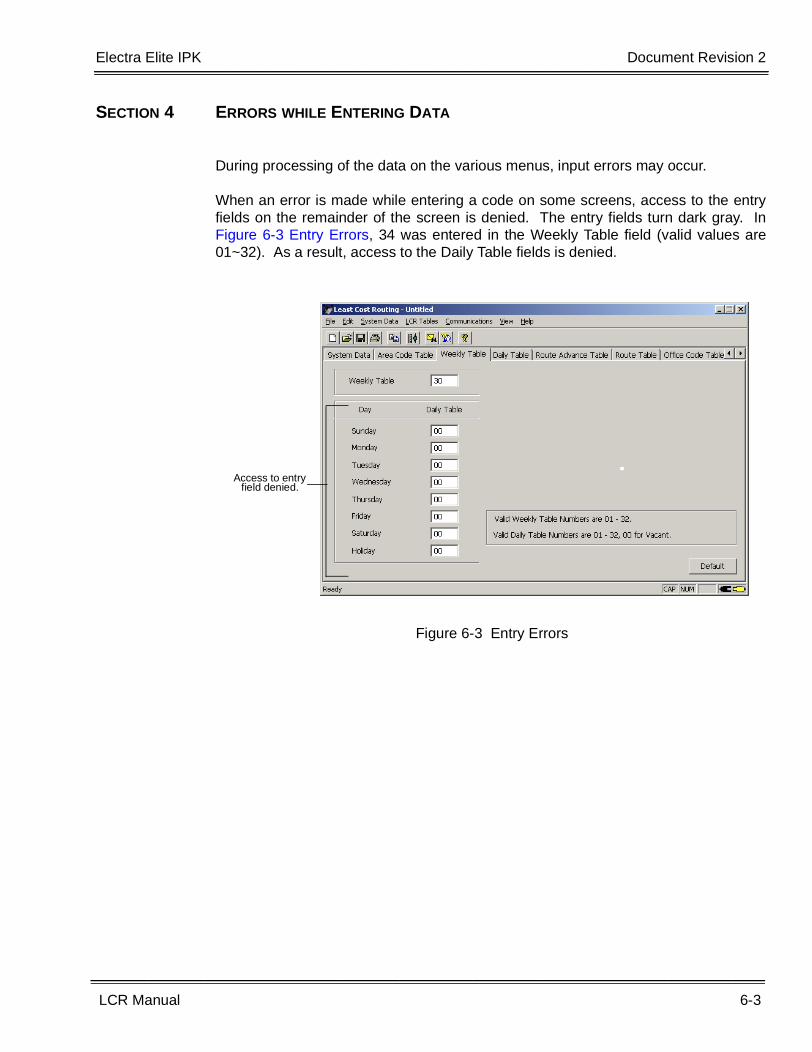
SECTION 4 ERRORS WHILE ENTERING DATA
During processing of the data on the various menus, input errors may occur.
When an error is made while entering a code on some screens, access to the entryfields on the remainder of the screen is denied. The entry fields turn dark gray. InFigure 6-3 Entry Errors, 34 was entered in the Weekly Table field (valid values are01~32). As a result, access to the Daily Table fields is denied.
Figure 6-3 Entry Errors
Access to entry field denied.
6-4 LCR Programming
___________________________________________________________________________________
___________________________________________________________________________________Document Revision 2 Electra Elite IPK
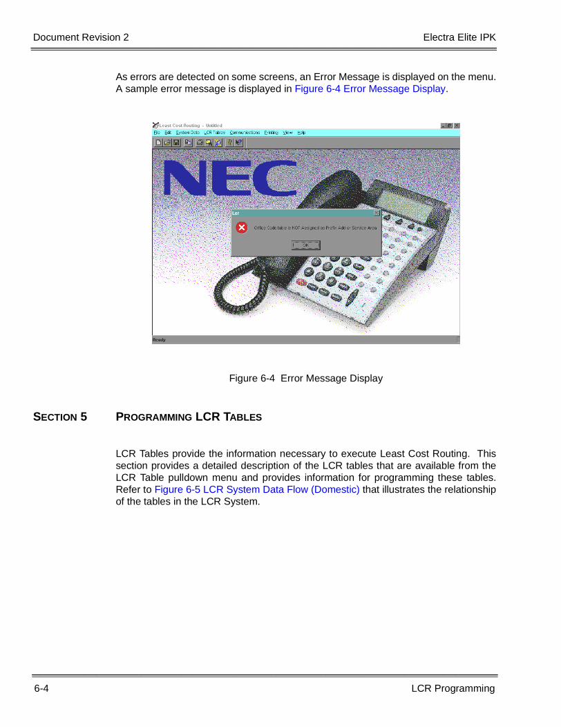
As errors are detected on some screens, an Error Message is displayed on the menu.A sample error message is displayed in Figure 6-4 Error Message Display.
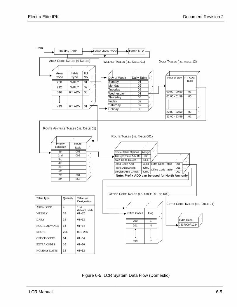
SECTION 5 PROGRAMMING LCR TABLES
LCR Tables provide the information necessary to execute Least Cost Routing. Thissection provides a detailed description of the LCR tables that are available from theLCR Table pulldown menu and provides information for programming these tables.Refer to Figure 6-5 LCR System Data Flow (Domestic) that illustrates the relationshipof the tables in the LCR System.
Figure 6-4 Error Message Display
Electra Elite IPK Document Revision 2
LCR Manual 6-5
___________________________________________________________________________________
___________________________________________________________________________________
Figure 6-5 LCR System Data Flow (Domestic)
AREA CODE TABLES (4 TABLES)
Area Code
Table Type
TblNo
200 WKLY 01
212 WKLY 02
516 RT ADV 05
713 RT ADV 01
�
������������������������������������
�����������������������������������
WEEKLY TABLES (I.E. TABLE 01)
Day of Week Daily TableSunday 01Monday 02Tuesday 05Wednesday 01Thursday 05Friday 02Saturday 32Holiday 00
�����������
����������
�����������
����������
��������������������
�������������������
������������
�����������
������������������������������
�����������
���������
�
����������������������������
�
����������������������������
��
��������������������������������������
����������������������������������
�
�����������������������������������
�������������������������������������
DAILY TABLES (I.E. TABLE 12)
Hour of Day RT. ADV. Table
00:00 - 00:59 03
01:00 - 01:59 00
22:00 - 22:59 02
23:00 - 23:59 01
����������
��������
���������������
��������
������
����������
�������
����������
�������
ROUTE ADVANCE TABLES (I.E. TABLE 01)
Priority Selection
Route
Table1st 001
2nd 0023rd4th
5th6th
7th 2348th 255
�
��������������������������������
��������������������������������
��������������������������������
��������������������������������
�������������������������������
�
��������������������������������
�������������������������������
�
�������������������������������
�
����������������������������
ROUTE TABLES (I.E. TABLE 001)
Route Table Options AssignTrkGrp/Route Adv Bl 02
Area Code Delete DELExtra Code Add ADD Extra Code Table 001
Prefix Add/Check CHKOffice Code Table
001Service Area Check CHK 002
�
��������������������������������������
�������������������������������������
��
��������������������������������������
�
��������������������������������������
��
������������������������������������
�������������������������������������
OFFICE CODE TABLES (I.E. TABLE 001 OR 002)
Office Codes Flag
200 S
201 N
999 P
�
����������������������������������
�
�����������������������������������
������������������������
�����������������������
��
����������������������������������
EXTRA CODE TABLES (I.E. TABLE 01)
Extra Code
7537000P1234
������������
���������
Table Type Quantity Table No. Designation
AREA CODE
WEEKLY
DAILY
ROUTE ADVANCE
ROUTE
OFFICE CODES
EXTRA CODES
HOLIDAY DATES
4
32
32
64
256
64
16
32
1~4(0 Not Used)01~32
01~32
01~64
001~256
01~64
01~16
01~32
From
�����������
���������
Holiday Table Home NPAHome Area Code
���������������
������������
�
��������������������������������������
����������
��������
���������������
Note: Prefix ADD can be used for North Am. only
6-6 LCR Programming
___________________________________________________________________________________
___________________________________________________________________________________Document Revision 2 Electra Elite IPK
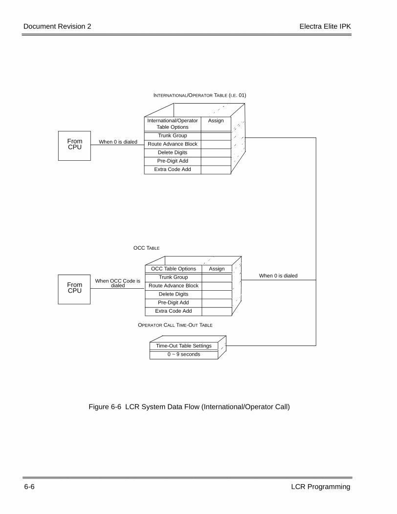
Figure 6-6 LCR System Data Flow (International/Operator Call)
International/Operator Table Options
Assign
Trunk Group
Route Advance Block
Delete Digits
Pre-Digit Add
Extra Code Add
��
�������������������������������������������������������������
�
��������������������������������������������
���������������������������������������������
������������������������������������������������
�������������������������������������������
�
����������������������������������������������������������
From CPU
When 0 is dialed
From CPU
When OCC Code is dialed
OCC TABLE
OCC Table Options Assign
Trunk Group
Route Advance Block
Delete Digits
Pre-Digit Add
Extra Code Add
����������������
��������������
�������������������������
���������������������
�
��������������������������������
�������������������������������
OPERATOR CALL TIME-OUT TABLE
Time-Out Table Settings
0 ~ 9 seconds�
������������������������������
�������������������
When 0 is dialed
INTERNATIONAL/OPERATOR TABLE (I.E. 01)
�
�����������������������������������������������������
������������
����������
�
�����������������������������������
Electra Elite IPK Document Revision 2
LCR Manual 6-7
___________________________________________________________________________________
___________________________________________________________________________________
5.1 Area Code Tables
5.1.1 Description
There are four Area Code Tables. Each table contains all possible AreaCodes and contains data that specifies whether the Weekly Table, orRoute Advance Table (Bypass or Vacant) is referenced when a specifiedArea Code is dialed.
� If specific hours for LCR routes are required, the Weekly and DailyTables must be programmed.
5.1.2 Area Code Table Assignments
Area Code Table – Enter the Area Code Table number (1~4) or click thepulldown menu to display the options.
Figure 6-7 Area Code Table
6-8 LCR Programming
___________________________________________________________________________________
___________________________________________________________________________________Document Revision 2 Electra Elite IPK
Area Code – Enter area code number (200~999). The number enteredin this field is displayed at the top of the Area Code list in the body of thescreen and the numbers in the remainder of the list are incremented inascending order. Area codes are listed on the screen in increments of10. The scroll buttons, located in the bottom right corner of the screen,allow the user to scroll up and down the list. The list is increased ordecreased by 10. (Refer to Figure 6-7 Area Code Table.) When theup/down button is pressed, the list decrements/increments by 10. Forexample, if the numbers 200~209 are displayed and the down scrollbutton is pressed, the numbers 210~219 are displayed.
Table Type - Specify table to which to assign the area code. The TableType options include:
� Vacant This selection specifies that no data is assigned to the selectedarea code. If Vacant is assigned, the call is not routed. This optionis the default setting.
� Weekly Tables This selection accesses the Weekly Table. Using this table resultsin the selection of the Route Advance Tables (via Daily Tables).Enter the desired table number in the field to the right of theselection. Valid table numbers are 01~32.
� Route Advance Table This selection accesses Route Advance Tables. Enter the desiredtable number in the field to the right of the selection. The valid tablenumbers are 01~64.
� Bypass This selection causes the selected Area Code to bypass LeastCost Routing and access Trunk Group 1.
Table No. – This allows the user to enter the table numbers. This field isnot displayed unless the Weekly or Route Advance Table Types areselected.
The Default, OK, and Cancel buttons allow the user to set all areacodes back to the default settings, to save the changes and exit thescreen, or to cancel the changes and exit the screen.
Electra Elite IPK Document Revision 2
LCR Manual 6-9
___________________________________________________________________________________
___________________________________________________________________________________
5.2 Weekly Tables
5.2.1 Description
There are 32 Weekly Tables (01~32). Each table contains seven itemsthat correspond to the days of the week. These tables designate whichDaily Table is referenced.
5.2.2 Weekly Table Assignments
Weekly Table – Enter the Weekly Table number (01~32).
Daily Table – Beside each day of the week, the user can enter the DailyTable number. Valid values are 00~32, 00 indicates the table is vacantor not assigned. The default setting is 00.
The Default, OK, and Cancel buttons allow the user to set all areacodes back to the default settings, to save the changes and exit thescreen, or to cancel the changes and exit the screen.
Figure 6-8 Weekly Table
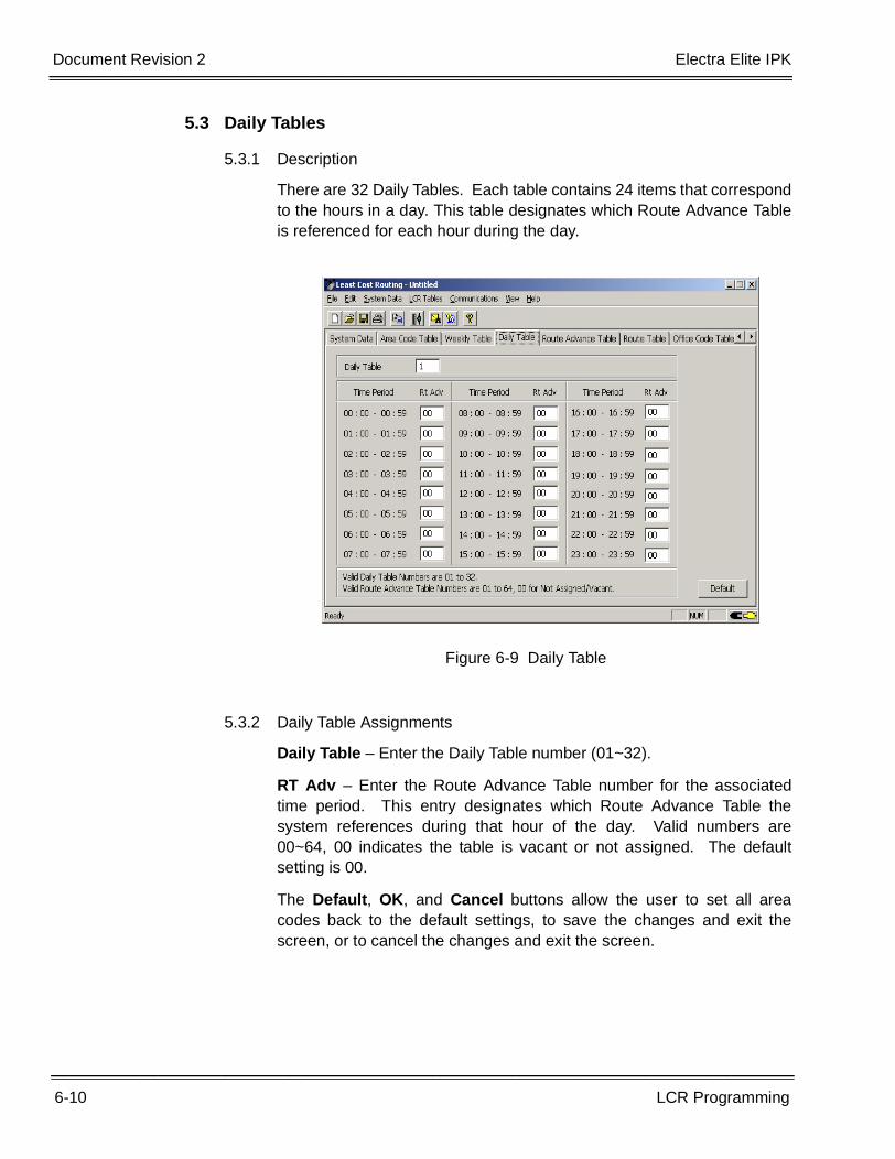
6-10 LCR Programming
___________________________________________________________________________________
___________________________________________________________________________________Document Revision 2 Electra Elite IPK
5.3 Daily Tables
5.3.1 Description
There are 32 Daily Tables. Each table contains 24 items that correspondto the hours in a day. This table designates which Route Advance Tableis referenced for each hour during the day.
5.3.2 Daily Table Assignments
Daily Table – Enter the Daily Table number (01~32).
RT Adv – Enter the Route Advance Table number for the associatedtime period. This entry designates which Route Advance Table thesystem references during that hour of the day. Valid numbers are00~64, 00 indicates the table is vacant or not assigned. The defaultsetting is 00.
The Default, OK, and Cancel buttons allow the user to set all areacodes back to the default settings, to save the changes and exit thescreen, or to cancel the changes and exit the screen.
Figure 6-9 Daily Table
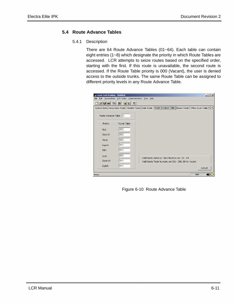
Electra Elite IPK Document Revision 2
LCR Manual 6-11
___________________________________________________________________________________
___________________________________________________________________________________
5.4 Route Advance Tables
5.4.1 Description
There are 64 Route Advance Tables (01~64). Each table can containeight entries (1~8) which designate the priority in which Route Tables areaccessed. LCR attempts to seize routes based on the specified order,starting with the first. If this route is unavailable, the second route isaccessed. If the Route Table priority is 000 (Vacant), the user is deniedaccess to the outside trunks. The same Route Table can be assigned todifferent priority levels in any Route Advance Table.
Figure 6-10 Route Advance Table
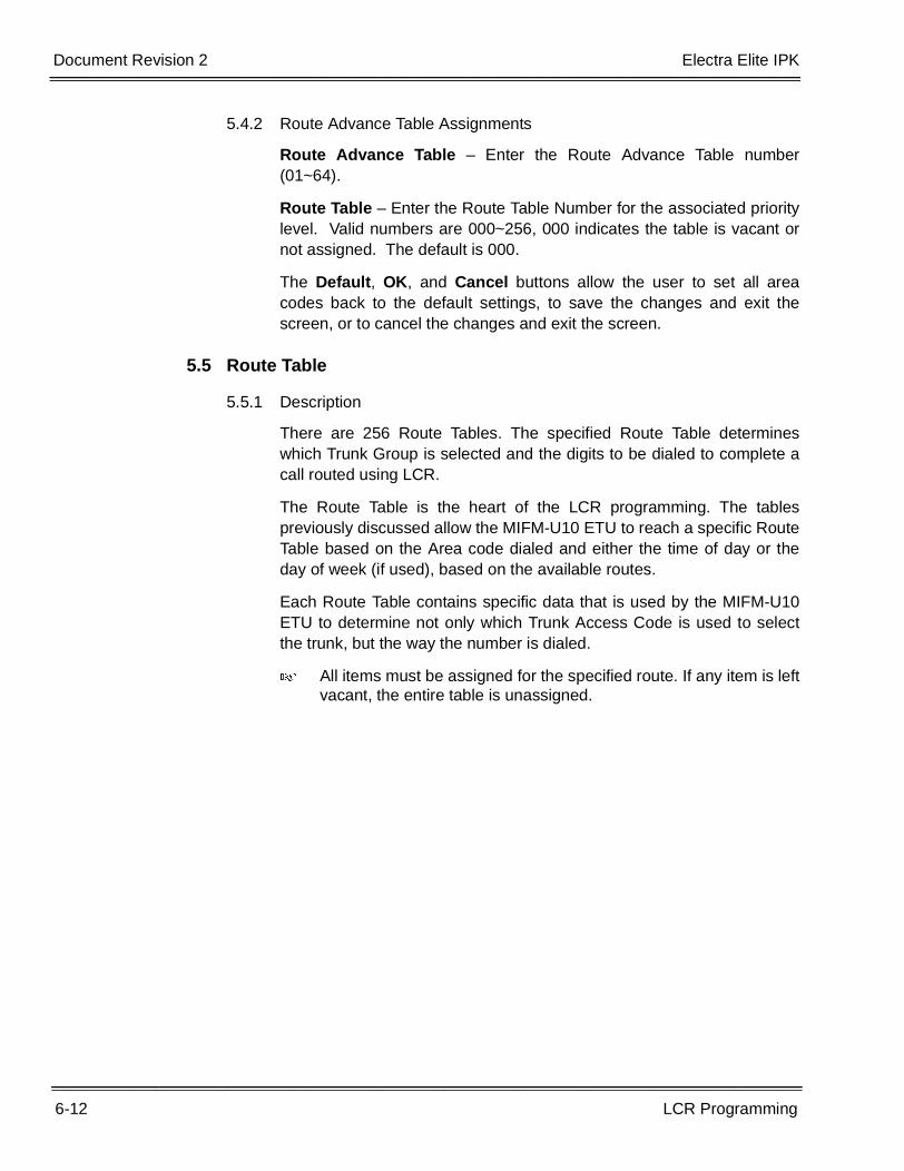
6-12 LCR Programming
___________________________________________________________________________________
___________________________________________________________________________________Document Revision 2 Electra Elite IPK
5.4.2 Route Advance Table Assignments
Route Advance Table – Enter the Route Advance Table number(01~64).
Route Table – Enter the Route Table Number for the associated prioritylevel. Valid numbers are 000~256, 000 indicates the table is vacant ornot assigned. The default is 000.
The Default, OK, and Cancel buttons allow the user to set all areacodes back to the default settings, to save the changes and exit thescreen, or to cancel the changes and exit the screen.
5.5 Route Table
5.5.1 Description
There are 256 Route Tables. The specified Route Table determineswhich Trunk Group is selected and the digits to be dialed to complete acall routed using LCR.
The Route Table is the heart of the LCR programming. The tablespreviously discussed allow the MIFM-U10 ETU to reach a specific RouteTable based on the Area code dialed and either the time of day or theday of week (if used), based on the available routes.
Each Route Table contains specific data that is used by the MIFM-U10ETU to determine not only which Trunk Access Code is used to selectthe trunk, but the way the number is dialed.
� All items must be assigned for the specified route. If any item is leftvacant, the entire table is unassigned.
Electra Elite IPK Document Revision 2
LCR Manual 6-13
___________________________________________________________________________________
___________________________________________________________________________________
5.5.2 Route Table Assignments
Route Table – Enter the Route Table number. Valid numbers are001~256. The information on the rest of the screen applies to thedesignated Route Table.
Trunk Group – Three selections are available for this option:
� Vacant – The Trunk Group is not assigned. Vacant is the defaultsetting.
� Trunk Group - When this is selected, another field is displayedallowing the user to enter the Trunk Group number. Valid TrunkGroups are 1~32.
� Local trunks should be assigned to Trunk Group 1 in systemdata. When a number is dialed that bypasses LCR, thesystem accesses Trunk Group 1 and dials the number.
� Route Advance - Selecting this displays another field that allowsthe user to enter the Route Advance Block number. Valid RouteAdvance Blocks are 1-32.
Figure 6-11 Route Table
6-14 LCR Programming
___________________________________________________________________________________
___________________________________________________________________________________Document Revision 2 Electra Elite IPK
Area Code Deletion – LCR is area code based. Therefore, an areacode is required to properly route calls. This selection identifies whetheror not the area code, dialed by the caller, is dialed out on a selectedtrunk. After a Route Table and a Trunk Group are selected (dependingon the trunk service provided) the area code may or may not be requiredto complete the call. Valid entries for this option include:
� Vacant – Indicates that no data is assigned. This is the defaultsetting.
� Do Not Delete – This selection should be assigned if the areacode is required as part of the dialed number.
� Delete – This selection should be assigned if the area code mustbe deleted to complete the call on the selected Trunk Group.
� LCR always inserts the Home NPA (local area code) forrouting only when local calls are routed using LCR. If theHome NPA is required for dialing, the Home NPA must beadded via the Extra Code Add Table.
Extra Code Add – In some applications, it may be necessary to add anExtra Code in front of the number to be dialed. Three selections areavailable for this option:
� Add Table – When this is selected, another field is displayedallowing the user to enter the Extra Code Table number. ValidExtra Code Table numbers are 1~16. This number is added to thebeginning of the dialed number.
� Do Not Add – Select this option when no extra codes are to beused when the number is dialed.
� Vacant – Select this option when no data is assigned. This is thedefault setting.
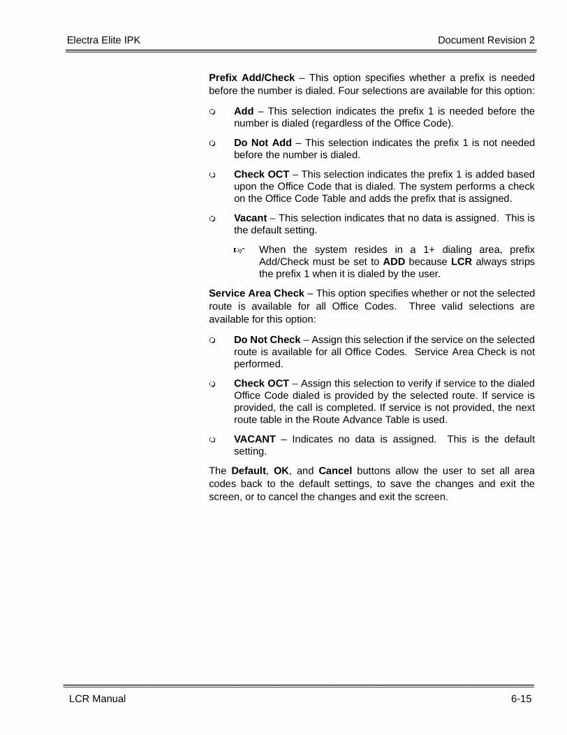
Electra Elite IPK Document Revision 2
LCR Manual 6-15
___________________________________________________________________________________
___________________________________________________________________________________
Prefix Add/Check – This option specifies whether a prefix is neededbefore the number is dialed. Four selections are available for this option:
� Add – This selection indicates the prefix 1 is needed before thenumber is dialed (regardless of the Office Code).
� Do Not Add – This selection indicates the prefix 1 is not neededbefore the number is dialed.
� Check OCT – This selection indicates the prefix 1 is added basedupon the Office Code that is dialed. The system performs a checkon the Office Code Table and adds the prefix that is assigned.
� Vacant – This selection indicates that no data is assigned. This isthe default setting.
� When the system resides in a 1+ dialing area, prefixAdd/Check must be set to ADD because LCR always stripsthe prefix 1 when it is dialed by the user.
Service Area Check – This option specifies whether or not the selectedroute is available for all Office Codes. Three valid selections areavailable for this option:
� Do Not Check – Assign this selection if the service on the selectedroute is available for all Office Codes. Service Area Check is notperformed.
� Check OCT – Assign this selection to verify if service to the dialedOffice Code dialed is provided by the selected route. If service isprovided, the call is completed. If service is not provided, the nextroute table in the Route Advance Table is used.
� VACANT – Indicates no data is assigned. This is the defaultsetting.
The Default, OK, and Cancel buttons allow the user to set all areacodes back to the default settings, to save the changes and exit thescreen, or to cancel the changes and exit the screen.
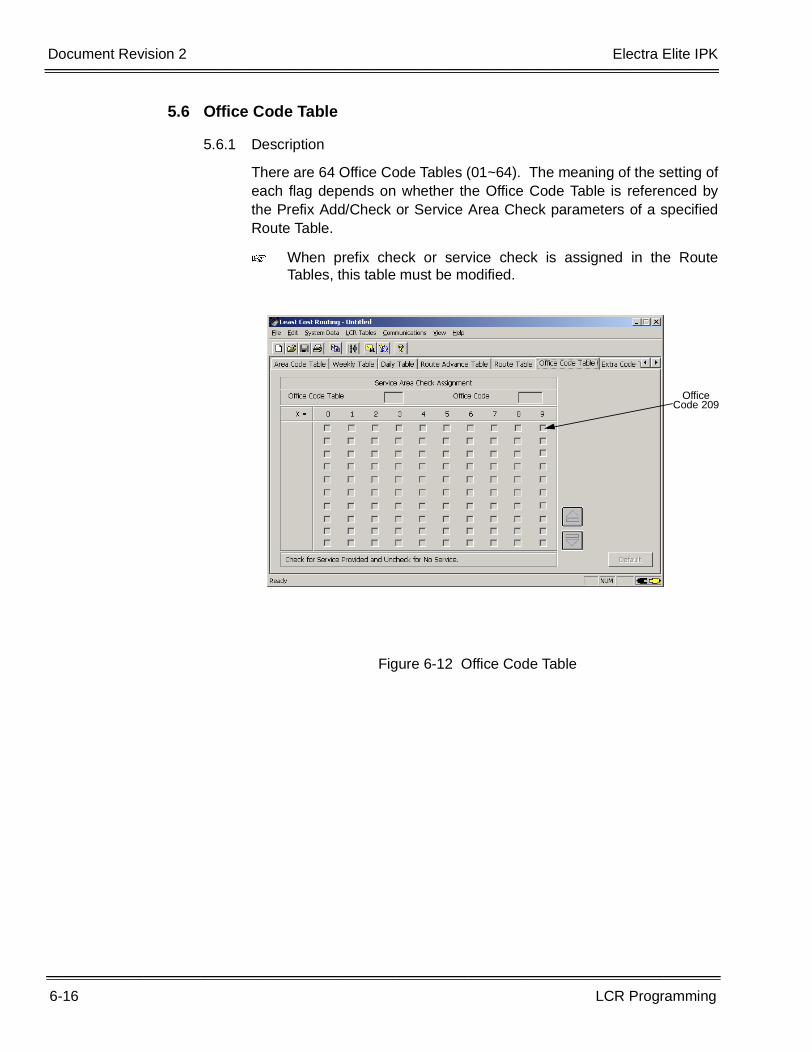
6-16 LCR Programming
___________________________________________________________________________________
___________________________________________________________________________________Document Revision 2 Electra Elite IPK
5.6 Office Code Table
5.6.1 Description
There are 64 Office Code Tables (01~64). The meaning of the setting ofeach flag depends on whether the Office Code Table is referenced bythe Prefix Add/Check or Service Area Check parameters of a specifiedRoute Table.
� When prefix check or service check is assigned in the RouteTables, this table must be modified.
Figure 6-12 Office Code Table
Office Code 209
Electra Elite IPK Document Revision 2
LCR Manual 6-17
___________________________________________________________________________________
___________________________________________________________________________________
5.6.2 Office Code Table Assignments
Office Code Table – Enter the Office Code Table number (01~64).
Office Code – Enter the Office Code number (200~999). The OfficeCode number (200~999) can be entered in the box. The body of thescreen displays 100 office codes at a time. The X= at the top of thescreen indicates the third digit of the office code. The 2-digit numberwith the X appended to it (displayed on the left side of the screen),indicates the first two digits of the office code. To find the number 209,find 20X on the left side of the screen and then find the number 9 (listedin the row above the check boxes). Refer to Figure 6-12 Office CodeTable.
The Office Code number that is entered in the field at the top of thescreen determines the areas codes listed in the remainder of the screen.For example, when any 3-digit number beginning with 2 is entered in theOffice Code field, all 200 office codes are displayed (20X ~ 29X).
The scroll buttons, located in the bottom right corner of the screen, allowthe user to scroll up/down the list in increments of 100. (Refer to Figure6-7 Area Code Table.) When the up/down button is pressed, the listdecrements/increments by 100. For example, if the numbers 200~299are displayed and the down scroll button is pressed, the numbers300~399 are displayed.
Prefix Add/No Prefix – To assign prefix 1 to the dialed office code, clickin the blank associated with the office code. A check mark is placed inthe box. If no prefix is dialed, either leave the box blank (default setting)or if a check is in the box, click inside the box to remove it.
The Default, OK, and Cancel buttons allow the user to set all areacodes back to the default settings, to save the changes and exit thescreen, or to cancel the changes and exit the screen.
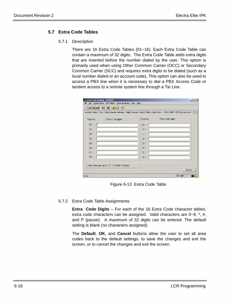
6-18 LCR Programming
___________________________________________________________________________________
___________________________________________________________________________________Document Revision 2 Electra Elite IPK
5.7 Extra Code Tables
5.7.1 Description
There are 16 Extra Code Tables (01~16). Each Extra Code Table cancontain a maximum of 32 digits. The Extra Code Table adds extra digitsthat are inserted before the number dialed by the user. This option isprimarily used when using Other Common Carrier (OCC) or SecondaryCommon Carrier (SCC) and requires extra digits to be dialed (such as alocal number dialed or an account code). This option can also be used toaccess a PBX line when it is necessary to dial a PBX Access Code ortandem access to a remote system line through a Tie Line.
5.7.2 Extra Code Table Assignments
Extra Code Digits – For each of the 16 Extra Code character tables,extra code characters can be assigned. Valid characters are 0~9, *, #,and P (pause). A maximum of 32 digits can be entered. The defaultsetting is blank (no characters assigned).
The Default, OK, and Cancel buttons allow the user to set all areacodes back to the default settings, to save the changes and exit thescreen, or to cancel the changes and exit the screen.
Figure 6-13 Extra Code Table
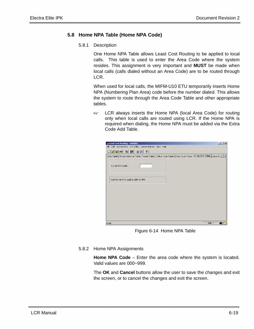
Electra Elite IPK Document Revision 2
LCR Manual 6-19
___________________________________________________________________________________
___________________________________________________________________________________
5.8 Home NPA Table (Home NPA Code)
5.8.1 Description
One Home NPA Table allows Least Cost Routing to be applied to localcalls. This table is used to enter the Area Code where the systemresides. This assignment is very important and MUST be made whenlocal calls (calls dialed without an Area Code) are to be routed throughLCR.
When used for local calls, the MIFM-U10 ETU temporarily inserts HomeNPA (Numbering Plan Area) code before the number dialed. This allowsthe system to route through the Area Code Table and other appropriatetables.
� LCR always inserts the Home NPA (local Area Code) for routingonly when local calls are routed using LCR. If the Home NPA isrequired when dialing, the Home NPA must be added via the ExtraCode Add Table.
5.8.2 Home NPA Assignments
Home NPA Code – Enter the area code where the system is located.Valid values are 000~999.
The OK and Cancel buttons allow the user to save the changes and exitthe screen, or to cancel the changes and exit the screen.
Figure 6-14 Home NPA Table
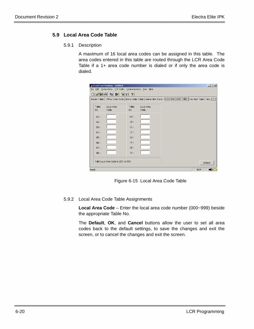
6-20 LCR Programming
___________________________________________________________________________________
___________________________________________________________________________________Document Revision 2 Electra Elite IPK
5.9 Local Area Code Table
5.9.1 Description
A maximum of 16 local area codes can be assigned in this table. Thearea codes entered in this table are routed through the LCR Area CodeTable if a 1+ area code number is dialed or if only the area code isdialed.
5.9.2 Local Area Code Table Assignments
Local Area Code – Enter the local area code number (000~999) besidethe appropriate Table No.
The Default, OK, and Cancel buttons allow the user to set all areacodes back to the default settings, to save the changes and exit thescreen, or to cancel the changes and exit the screen.
Figure 6-15 Local Area Code Table
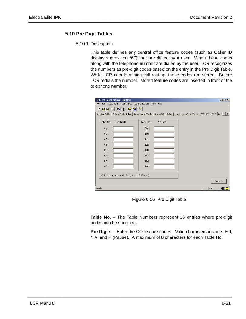
Electra Elite IPK Document Revision 2
LCR Manual 6-21
___________________________________________________________________________________
___________________________________________________________________________________
5.10 Pre Digit Tables
5.10.1 Description
This table defines any central office feature codes (such as Caller IDdisplay supression *67) that are dialed by a user. When these codesalong with the telephone number are dialed by the user, LCR recognizesthe numbers as pre-digit codes based on the entry in the Pre Digit Table.While LCR is determining call routing, these codes are stored. BeforeLCR redials the number, stored feature codes are inserted in front of thetelephone number.
Table No. – The Table Numbers represent 16 entries where pre-digitcodes can be specified.
Pre Digits – Enter the CO feature codes. Valid characters include 0~9,*, #, and P (Pause). A maximum of 8 characters for each Table No.
Figure 6-16 Pre Digit Table
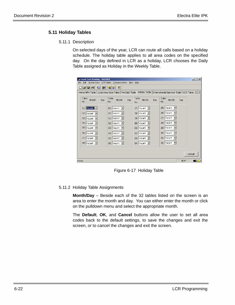
6-22 LCR Programming
___________________________________________________________________________________
___________________________________________________________________________________Document Revision 2 Electra Elite IPK
5.11 Holiday Tables
5.11.1 Description
On selected days of the year, LCR can route all calls based on a holidayschedule. The holiday table applies to all area codes on the specifiedday. On the day defined in LCR as a holiday, LCR chooses the DailyTable assigned as Holiday in the Weekly Table.
5.11.2 Holiday Table Assignments
Month/Day – Beside each of the 32 tables listed on the screen is anarea to enter the month and day. You can either enter the month or clickon the pulldown menu and select the appropriate month.
The Default, OK, and Cancel buttons allow the user to set all areacodes back to the default settings, to save the changes and exit thescreen, or to cancel the changes and exit the screen.
Figure 6-17 Holiday Table
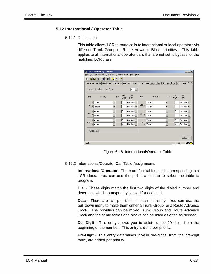
Electra Elite IPK Document Revision 2
LCR Manual 6-23
___________________________________________________________________________________
___________________________________________________________________________________
5.12 International / Operator Table
5.12.1 Description
This table allows LCR to route calls to international or local operators viadifferent Trunk Group or Route Advance Block priorities. This tableapplies to all international operator calls that are not set to bypass for thematching LCR class.
5.12.2 International/Operator Call Table Assignments
International/Operator - There are four tables, each corresponding to aLCR class. You can use the pull-down menu to select the table toprogram.
Dial - These digits match the first two digits of the dialed number anddetermine which route/priority is used for each call.
Data - There are two priorities for each dial entry. You can use thepull-down menu to make them either a Trunk Group, or a Route AdvanceBlock. The priorities can be mixed Trunk Group and Route AdvanceBlock and the same tables and blocks can be used as often as needed.
Del Digit - This entry allows you to delete up to 20 digits from thebeginning of the number. This entry is done per priority.
Pre-Digit - This entry determines if valid pre-digits, from the pre-digittable, are added per priority.
Figure 6-18 International/Operator Table
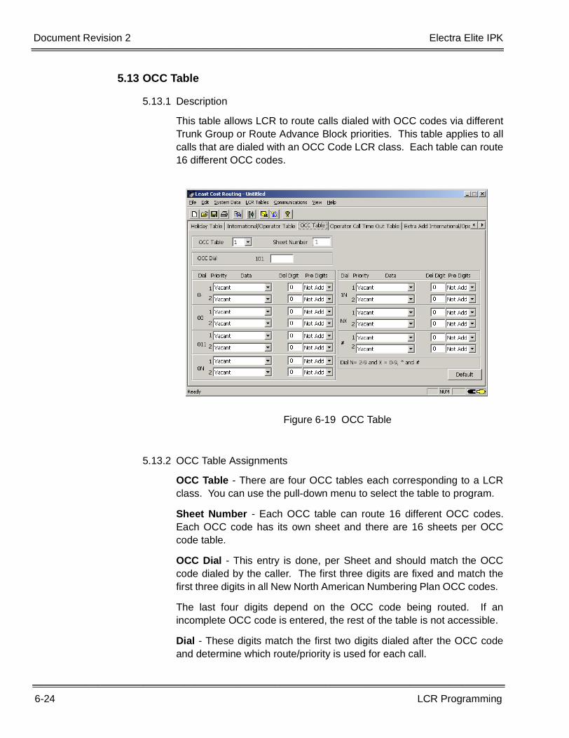
6-24 LCR Programming
___________________________________________________________________________________
___________________________________________________________________________________Document Revision 2 Electra Elite IPK
5.13 OCC Table
5.13.1 Description
This table allows LCR to route calls dialed with OCC codes via differentTrunk Group or Route Advance Block priorities. This table applies to allcalls that are dialed with an OCC Code LCR class. Each table can route16 different OCC codes.
5.13.2 OCC Table Assignments
OCC Table - There are four OCC tables each corresponding to a LCRclass. You can use the pull-down menu to select the table to program.
Sheet Number - Each OCC table can route 16 different OCC codes.Each OCC code has its own sheet and there are 16 sheets per OCCcode table.
OCC Dial - This entry is done, per Sheet and should match the OCCcode dialed by the caller. The first three digits are fixed and match thefirst three digits in all New North American Numbering Plan OCC codes.
The last four digits depend on the OCC code being routed. If anincomplete OCC code is entered, the rest of the table is not accessible.
Dial - These digits match the first two digits dialed after the OCC codeand determine which route/priority is used for each call.
Figure 6-19 OCC Table
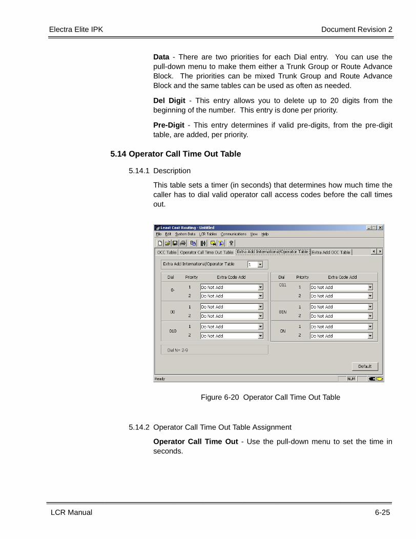
Electra Elite IPK Document Revision 2
LCR Manual 6-25
___________________________________________________________________________________
___________________________________________________________________________________
Data - There are two priorities for each Dial entry. You can use thepull-down menu to make them either a Trunk Group or Route AdvanceBlock. The priorities can be mixed Trunk Group and Route AdvanceBlock and the same tables can be used as often as needed.
Del Digit - This entry allows you to delete up to 20 digits from thebeginning of the number. This entry is done per priority.
Pre-Digit - This entry determines if valid pre-digits, from the pre-digittable, are added, per priority.
5.14 Operator Call Time Out Table
5.14.1 Description
This table sets a timer (in seconds) that determines how much time thecaller has to dial valid operator call access codes before the call timesout.
5.14.2 Operator Call Time Out Table Assignment
Operator Call Time Out - Use the pull-down menu to set the time inseconds.
Figure 6-20 Operator Call Time Out Table
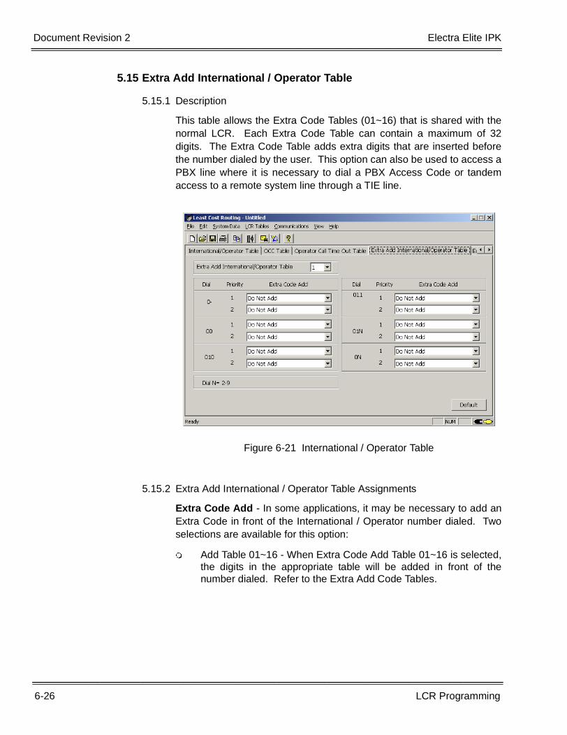
6-26 LCR Programming
___________________________________________________________________________________
___________________________________________________________________________________Document Revision 2 Electra Elite IPK
5.15 Extra Add International / Operator Table
5.15.1 Description
This table allows the Extra Code Tables (01~16) that is shared with thenormal LCR. Each Extra Code Table can contain a maximum of 32digits. The Extra Code Table adds extra digits that are inserted beforethe number dialed by the user. This option can also be used to access aPBX line where it is necessary to dial a PBX Access Code or tandemaccess to a remote system line through a TIE line.
5.15.2 Extra Add International / Operator Table Assignments
Extra Code Add - In some applications, it may be necessary to add anExtra Code in front of the International / Operator number dialed. Twoselections are available for this option:
� Add Table 01~16 - When Extra Code Add Table 01~16 is selected,the digits in the appropriate table will be added in front of thenumber dialed. Refer to the Extra Add Code Tables.
Figure 6-21 International / Operator Table
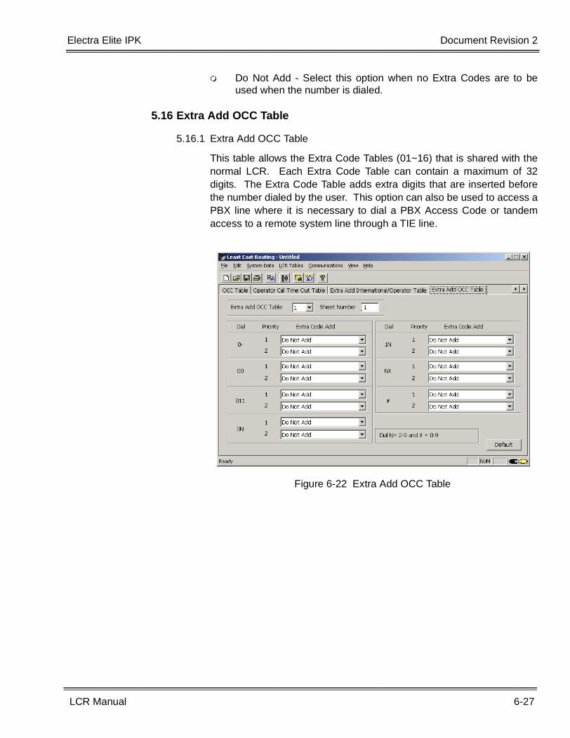
Electra Elite IPK Document Revision 2
LCR Manual 6-27
___________________________________________________________________________________
___________________________________________________________________________________
� Do Not Add - Select this option when no Extra Codes are to beused when the number is dialed.
5.16 Extra Add OCC Table
5.16.1 Extra Add OCC Table
This table allows the Extra Code Tables (01~16) that is shared with thenormal LCR. Each Extra Code Table can contain a maximum of 32digits. The Extra Code Table adds extra digits that are inserted beforethe number dialed by the user. This option can also be used to access aPBX line where it is necessary to dial a PBX Access Code or tandemaccess to a remote system line through a TIE line.
Figure 6-22 Extra Add OCC Table
6-28 LCR Programming
___________________________________________________________________________________
___________________________________________________________________________________Document Revision 2 Electra Elite IPK
5.16.2 Extra Add OCC Table Assignments
Extra Code Add - In some applications, it may be necessary to add anExtra Code in front of the OCC number dialed. Three selections areavailable for this option:
Extra Add OCC Table - There are four OCC Tables each correspondingto a LCR class. You can use the pull-down menu to select the table toprogram.
Sheet Number - Each OCC table has the ability to route 16 differentOCC codes. Each OCC code has its own sheet and there are 16 sheetsper OCC Code Table.
Extra Code Add - In some applications, it may be necessary to add anExtra Code in front of the International / Operator number dialed. Twoselections are available for this option:
• Add Table 01~16 - When this selection is made, the Extra Code AddTable needs to be filled in for the appropriate digits to be added.Refer to the Extra Code Add Tables. This number is added to thebeginning of the dialed number.
• Do Not Add - Select this option when no Extra Codes are to be usedwhen the number is dialed.
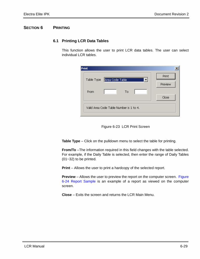
Electra Elite IPK Document Revision 2
LCR Manual 6-29
___________________________________________________________________________________
___________________________________________________________________________________
SECTION 6 PRINTING
6.1 Printing LCR Data Tables
This function allows the user to print LCR data tables. The user can selectindividual LCR tables.
Table Type – Click on the pulldown menu to select the table for printing.
From/To –The information required in this field changes with the table selected.For example, if the Daily Table is selected, then enter the range of Daily Tables(01~32) to be printed.
Print – Allows the user to print a hardcopy of the selected report.
Preview – Allows the user to preview the report on the computer screen. Figure6-24 Report Sample is an example of a report as viewed on the computerscreen.
Close – Exits the screen and returns the LCR Main Menu.
Figure 6-23 LCR Print Screen
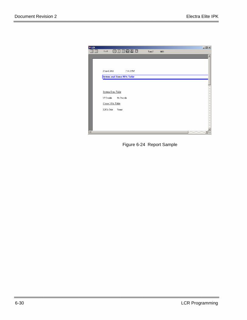
6-30 LCR Programming
___________________________________________________________________________________
___________________________________________________________________________________Document Revision 2 Electra Elite IPK
Figure 6-24 Report Sample
LCR Manual 7-1
___________________________________________________________________________________
___________________________________________________________________________________
Error Messages Chapter 7
SECTION 1 ERROR MESSAGES
The following error messages are used in this system.
Message: Function not available
Meaning: Attempted to use a function that has not been implemented
Message: Table number MUST be 01~32
Meaning: Attempted to specify an invalid table number (00 or 33~99)
Message: Table number MUST be 01~64
Meaning: Attempted to specify an invalid table number (00 or 65~99)
Message: Table number MUST be 1~4
Meaning: Attempted to specify an invalid table number (0 or 5~9)
Message: Area Code MUST be 200~999
Meaning: Attempted to specify an invalid Area Code (000 or 199)
Message: Table number MUST be 001~256
Meaning: Attempted to specify an invalid table number (000 or 257~999)
7-2 Error Messages
___________________________________________________________________________________
___________________________________________________________________________________Document Revision 2 Electra Elite IPK
Message: Office Code Tables MUST be different for Prefix Add and Service Area
Meaning: Attempted to specify the same Office Code Table as a Prefix Addfunction and as a Service Area function
Message: Office Code Table ALREADY assigned for Service Area Check
Meaning: Attempted to specify the Office Code Table as a Service Area functionwhen it is defined as a Prefix Add function
Message: Office Code Table ALREADY assigned for Prefix Add Check
Meaning: Attempted to specify the Office Code Table as a Service Area functionwhen it is defined as a Service Area function
Message: Office Code MUST be 200~999
Meaning: Attempted to specify an invalid Office Code (000~199)
Message: Office Code Tables MUST be assigned as Prefix Add or Service Area
Meaning: Attempted to bypass the Office Code Table assignment
Message: Office Code Table IS NOT ASSIGNED as Prefix Add or Service Area
Meaning: Attempted to bypass the Office Code Table assignment
Message: View NOT ALLOWED for this item
Meaning: Attempted to view an item that has no view screen
Message: Memory cannot be allocated
Meaning: Insufficient memory to perform the selected function
Message: Connected to Key System
Meaning: Attempted to initialize the communications values when the computer isconnected and accessing the Key System
Message: Bad port used
Meaning: An invalid serial port number was detected (INTERNAL)
Message: Bad Line Rate
Meaning: An invalid transmission rate was detected (INTERNAL)
Message: Bad Char Mode
Meaning: An invalid character mode was detected (INTERNAL)
Electra Elite IPK Document Revision 2
LCR Manual 7-3
___________________________________________________________________________________
___________________________________________________________________________________
Message: Bad Init Comm
Meaning: Attempted to initialize; the serial port failed (INTERNAL)
Message: No connection/access to Key System
Meaning: Attempted to up/down load before successfully connecting to the KeySystem
Message: Invalid Password! Please try again
Meaning: Attempted to specify an invalid password
Message: Invalid Password! Exiting to DOS
Meaning: Incorrect Password entered three times
Message: Invalid disk drive selected
Meaning: Attempted to specify an incorrect or nonexistent disk drive
Message: Customer directory not created
Meaning: Attempted to create a directory when a file exists with the same name (ordirectory creation privileges are denied)
Message: Window Display error (INTERNAL)
Meaning: An error was detected when attempting to display a window
Message: Mismatch Count Error (INTERNAL)
Meaning: An error was detected when attempting to retrieve an item from aselection list
Message: Item Count Error (INTERNAL)
Meaning: An error was detected when attempting to retrieve the default item froma selection list
Message: List Number Error (Internal)
Meaning: An invalid selection list was detected
Message: Unknown List Error
Meaning: An unknown error was detected during selection list processing
Message: File Create Error
Meaning: A creation error was detected during file processing
Message: File CRC Error
Meaning: A checksum error was detected during file processing
7-4 Error Messages
___________________________________________________________________________________
___________________________________________________________________________________Document Revision 2 Electra Elite IPK
Message: File Write Error
Meaning: A write error was detected during file processing
Message: File Close Error
Meaning: A close error was detected during file processing
Message: File Read Error
Meaning: A read error was detected during file processing
Message: In-line Tag Table item not found (Internal)
Meaning: The selected menu item could not be located
LCR Manual 8-1
___________________________________________________________________________________
___________________________________________________________________________________
LCR Flowcharts Chapter 8
SECTION 1 LCR FLOWCHARTS
1.1 General
This chapter contains flowcharts that show how the CPU routes a number whenit is dialed. Where applicable, the associated Memory Blocks that should beprogrammed are shown.
The following flowcharts are presented:
• LCR Flowchart 1 - Refer to Figure 8-1 LCR Flowchart 1.
• LCR Flowchart 2 - Refer to Figure 8-2 LCR Flowchart 2.
• LCR Flowchart 3 - Refer to Figure 8-3 LCR Flowchart 3.
• International/Operator Call Flowchart - Refer to Figure 8-4 International /Operator Call Flowchart.
• OCC Flowchart - Refer to Figure 8-5 OCC Flowchart.
• International/Operator/OCC Continuation Flowchart - Refer to Figure 8-6International / Operator / OCC Continuation Flowchart.
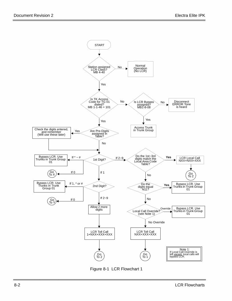
8-2 LCR Flowcharts
___________________________________________________________________________________
___________________________________________________________________________________Document Revision 2 Electra Elite IPK
Figure 8-1 LCR Flowchart 1
START
Station assigned LCR Class?
MB 4-40
Normal Operation(No LCR)
Yes
No
2nd Digit?
If 2~9
Allow 2 more digits
LCR Toll Call1+NXX+XXX+XXX
Go To 2
LCR Local CallNXX+NXX+XXX
Do the 1st~3rd digits match the Local Area Code
Table?
Yes
Is TK Access Code for TG 01
dialed?MB 1-1-46 = 101
No Is LCR Bypass assigned?MB1-8-08
Disconnect ERROR Tone
is heard
No
Yes
Are Pre-Digits assigned in
Table?
Check the digits entered, and remember
(Will use these later)Yes
Yes
Access Trunk in Trunk Group
No
1st Digit?If * ~ #Bypass LCR. Use
Trunks in Trunk Group 01
If 0Go To X
If 1
If 1, * or #Bypass LCR. Use Trunks in Trunk
Group 01
If 0Go To Y
If 2~9
No
Do the digits equal
N11?
Bypass LCR. Use Trunks in Trunk Group
01Yes
Local Call Override?(see Note 1)
No
Bypass LCR. Use Trunks in Trunk Group
01
Override
No Override
LCR Toll CallNXX+XXX+XXX
Go To 1
Note 1:If Local Call Override is left vacant, local calls will bypass LCR.
Go To 2
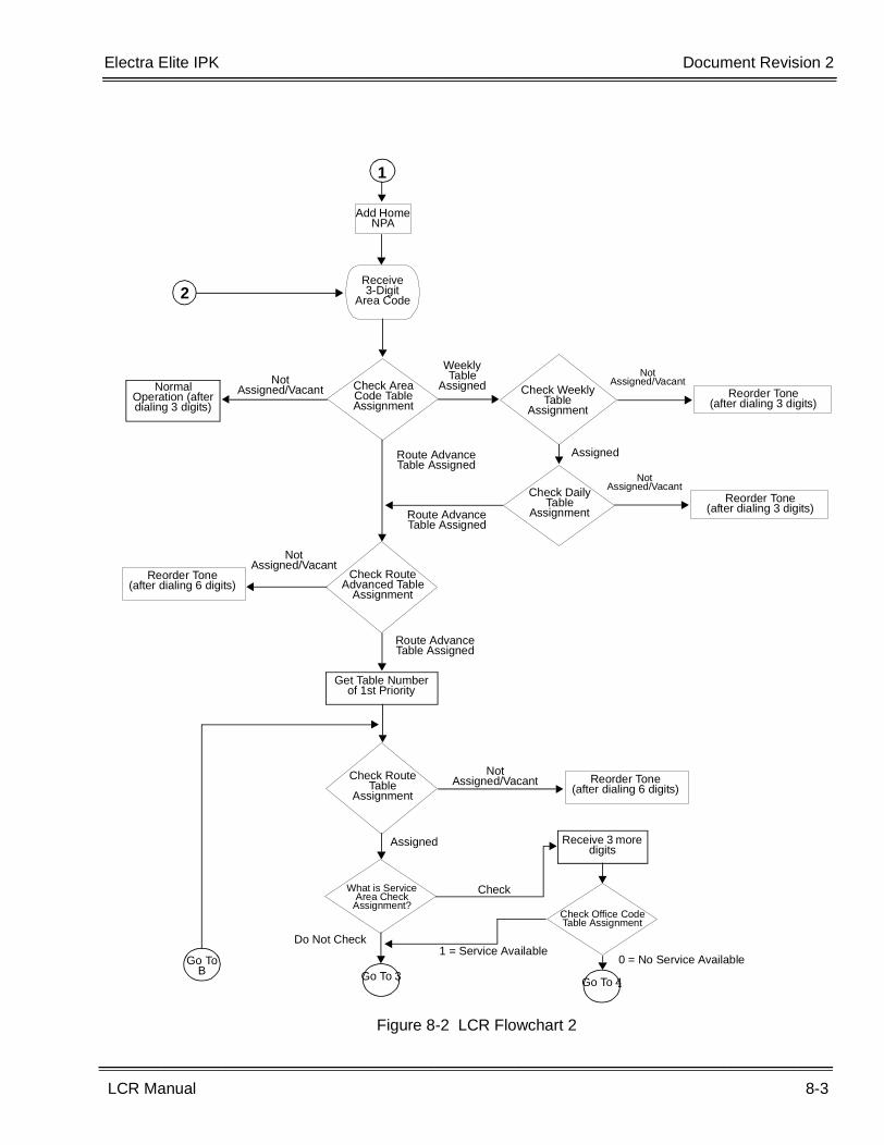
Electra Elite IPK Document Revision 2
LCR Manual 8-3
___________________________________________________________________________________
___________________________________________________________________________________
Figure 8-2 LCR Flowchart 2
Receive 3-Digit
Area Code
Add Home NPA
1
2
Check Weekly Table
Assignment
Reorder Tone(after dialing 6 digits)
Not Assigned/Vacant
Route Advance Table Assigned
Reorder Tone(after dialing 3 digits)
Not Assigned/Vacant
Weekly Table
AssignedNormal Operation (after dialing 3 digits)
Check Area Code Table Assignment
Check Daily Table
Assignment
Assigned
Route Advance Table Assigned
Not Assigned/Vacant
Reorder Tone(after dialing 3 digits)
Check Route Advanced Table
Assignment
Not Assigned/Vacant
Route Advance Table Assigned
Get Table Number of 1st Priority
Go To B
Check Route Table
Assignment
Reorder Tone(after dialing 6 digits)
Not Assigned/Vacant
Assigned
What is Service Area Check
Assignment?
Go To 3
Receive 3 more digits
Check
Do Not Check
Check Office Code Table Assignment
Go To 4
0 = No Service Available1 = Service Available
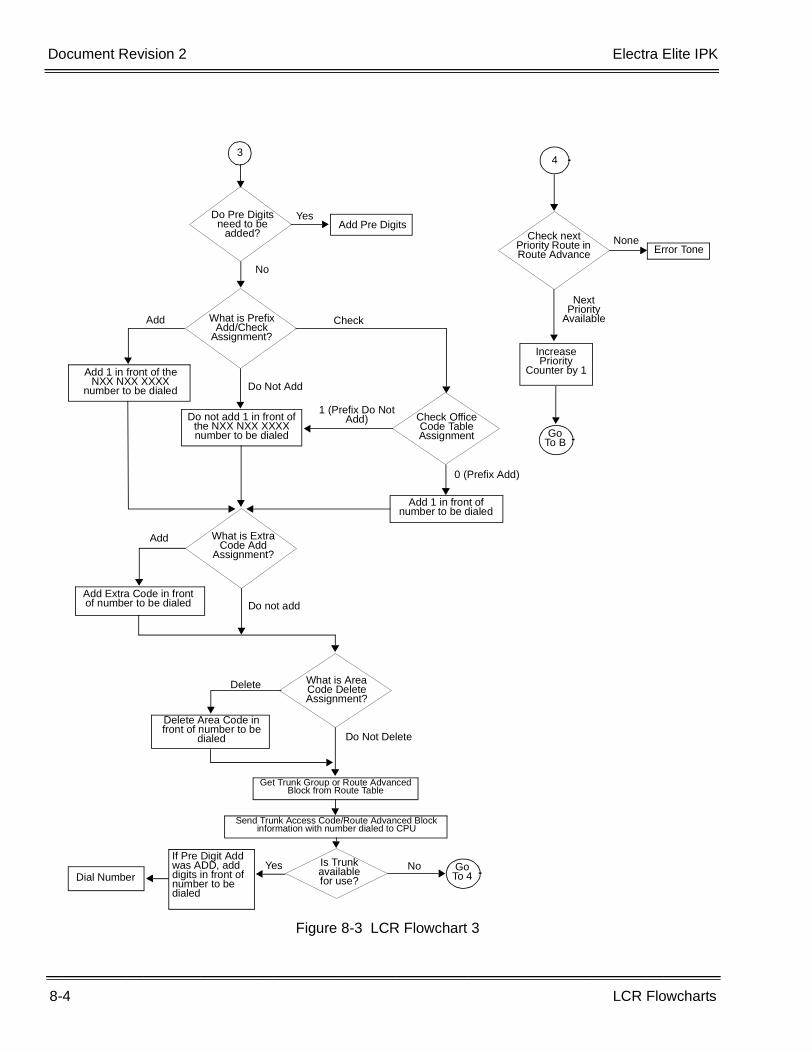
8-4 LCR Flowcharts
___________________________________________________________________________________
___________________________________________________________________________________Document Revision 2 Electra Elite IPK
Figure 8-3 LCR Flowchart 3
3
Do Pre Digits need to be
added?Add Pre Digits
Yes
No
What is Prefix Add/Check
Assignment?
4
Check next Priority Route in Route Advance Error Tone
None
Next Priority
Available
Increase Priority
Counter by 1
Go To B
Add 1 in front of the NXX NXX XXXX
number to be dialed
Check
Do not add 1 in front of the NXX NXX XXXX number to be dialed
Check Office Code Table Assignment
1 (Prefix Do Not Add)
0 (Prefix Add)
Add 1 in front of number to be dialed
What is Extra Code Add
Assignment?
Add
Add Extra Code in front of number to be dialed Do not add
What is Area Code Delete Assignment?
Dial Number
If Pre Digit Add was ADD, add digits in front of number to be dialed
Is Trunk available for use?
Yes No Go To 4
Delete Area Code in front of number to be
dialed
Delete
Do Not Delete
Get Trunk Group or Route Advanced Block from Route Table
Send Trunk Access Code/Route Advanced Block information with number dialed to CPU
Add
Do Not Add
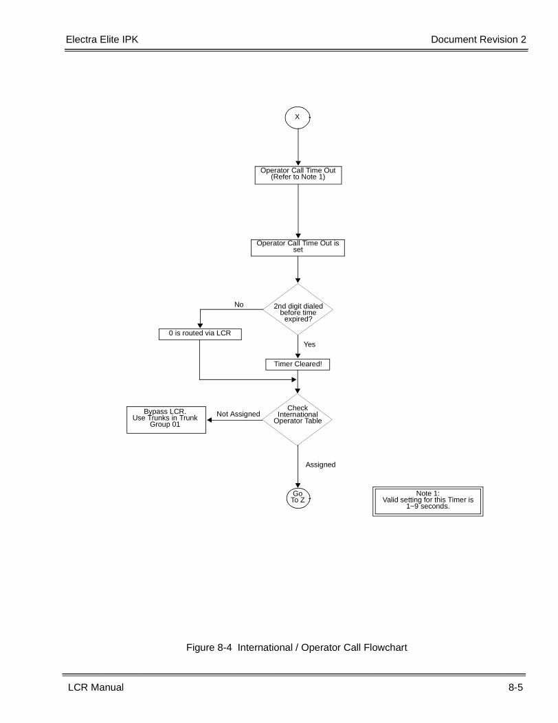
Electra Elite IPK Document Revision 2
LCR Manual 8-5
___________________________________________________________________________________
___________________________________________________________________________________
Figure 8-4 International / Operator Call Flowchart
X
Operator Call Time Out (Refer to Note 1)
Operator Call Time Out is set
2nd digit dialed before time
expired?
Yes
Timer Cleared!
0 is routed via LCR
No
Check International
Operator TableNot AssignedBypass LCR.
Use Trunks in Trunk Group 01
Go To Z
Assigned
Note 1:Valid setting for this Timer is
1~9 seconds.
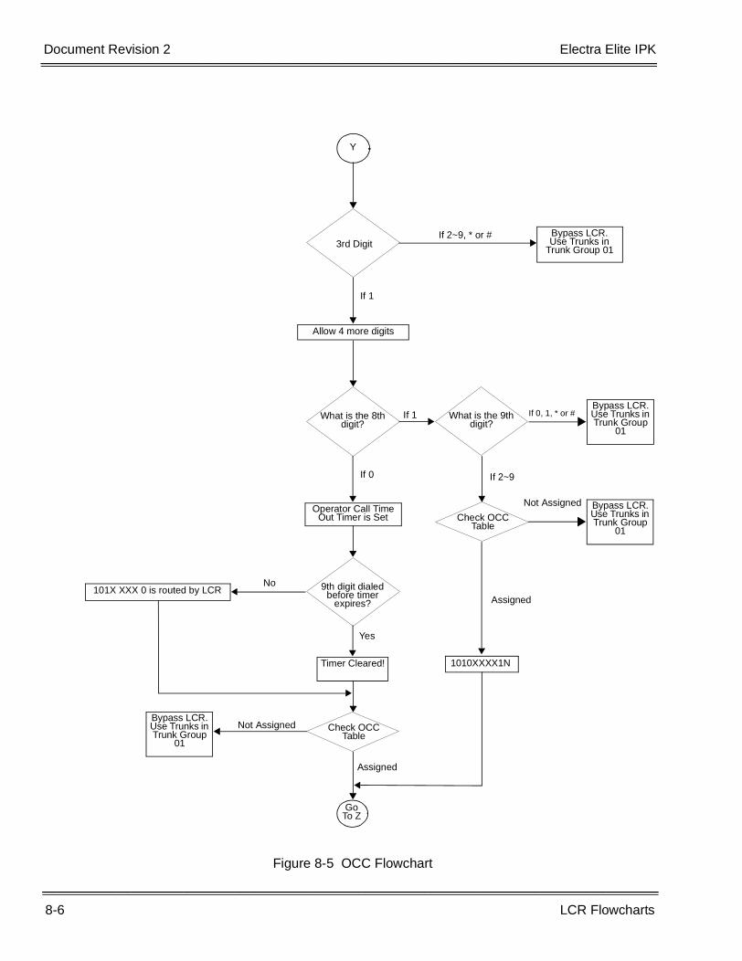
8-6 LCR Flowcharts
___________________________________________________________________________________
___________________________________________________________________________________Document Revision 2 Electra Elite IPK
Figure 8-5 OCC Flowchart
Y
3rd DigitIf 2~9, * or # Bypass LCR.
Use Trunks in Trunk Group 01
If 1
Allow 4 more digits
What is the 8th digit?
If 1 What is the 9th digit?
Bypass LCR.Use Trunks in Trunk Group
01
If 0, 1, * or #
If 0
Operator Call Time Out Timer is Set
9th digit dialed before timer
expires?
Yes
No101X XXX 0 is routed by LCR
Timer Cleared!
Check OCC Table
Bypass LCR.Use Trunks in Trunk Group
01
Not Assigned
Go To Z
Assigned
If 2~9
Check OCC Table
Bypass LCR.Use Trunks in Trunk Group
01
Not Assigned
1010XXXX1N
Assigned
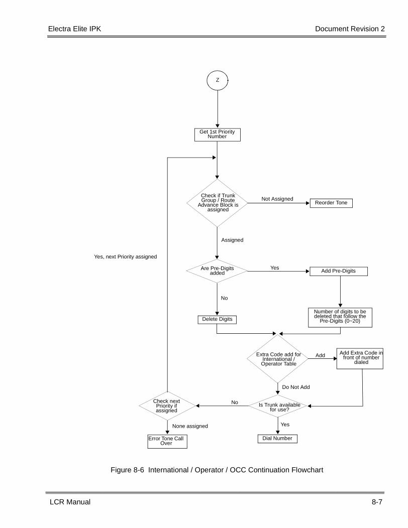
Electra Elite IPK Document Revision 2
LCR Manual 8-7
___________________________________________________________________________________
___________________________________________________________________________________
Figure 8-6 International / Operator / OCC Continuation Flowchart
Z
Get 1st Priority Number
Check if Trunk Group / Route
Advance Block is assigned
Reorder ToneNot Assigned
Assigned
Are Pre-Digits added Add Pre-DigitsYes
No
Delete DigitsNumber of digits to be deleted that follow the
Pre-Digits (0~20)
Extra Code add for International / Operator Table
Add Extra Code in front of number
dialedAdd
Is Trunk available for use?
Do Not Add
Yes
Dial Number
Check next Priority if assigned
No
Error Tone Call Over
None assigned
Yes, next Priority assigned

8-8 LCR Flowcharts
___________________________________________________________________________________
___________________________________________________________________________________Document Revision 2 Electra Elite IPK
THIS PAGE INTENTIONALLY LEFT BLANK
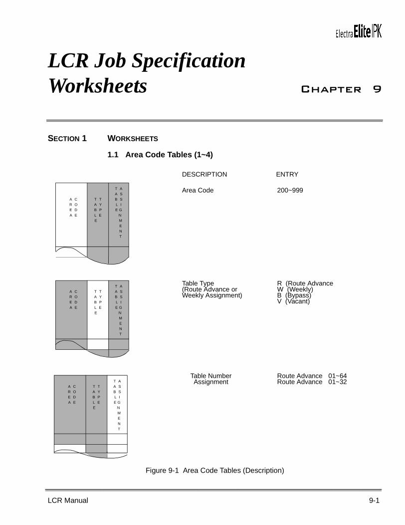
LCR Manual 9-1
___________________________________________________________________________________
___________________________________________________________________________________
LCR Job Specification Worksheets Chapter 9
SECTION 1 WORKSHEETS
1.1 Area Code Tables (1~4)
Figure 9-1 Area Code Tables (Description)
A CR OE DA E
T TA YB PL E E
T AA SB SL IE G N M E N T
A CR OE DA E
T TA YB PL E E
T AA SB SL IE G N M E N T
A CR OE DA E
T TA YB PL E E
T AA SB SL IE G N M E N T
Area Code
Table Type (Route Advance or Weekly Assignment)
R (Route AdvanceW (Weekly)B (Bypass)V (Vacant)
Table Number Assignment
Route Advance 01~64Route Advance 01~32
DESCRIPTION ENTRY
200~999
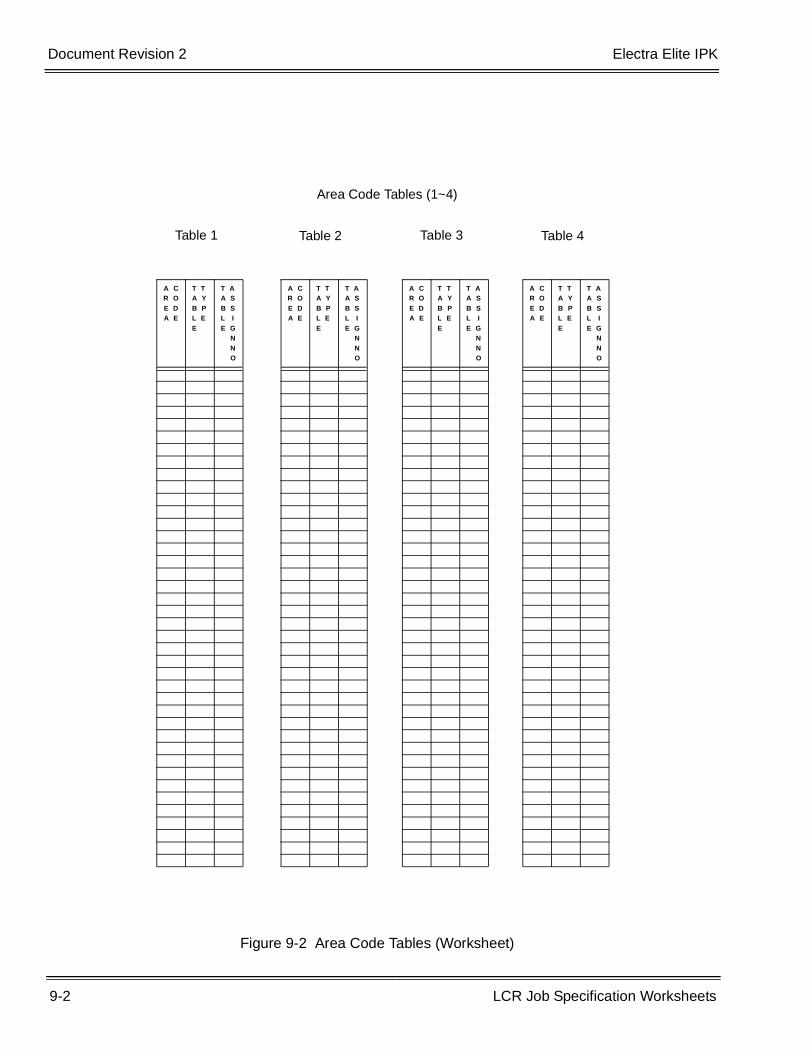
9-2 LCR Job Specification Worksheets
___________________________________________________________________________________
___________________________________________________________________________________Document Revision 2 Electra Elite IPK
Figure 9-2 Area Code Tables (Worksheet)
A CR OE DA E
T TA YB PL EE
T AA SB SL IE G N N O
A CR OE DA E
T TA YB PL EE
T AA SB SL IE G N N O
A CR OE DA E
T TA YB PL EE
T AA SB SL IE G N N O
A CR OE DA E
T TA YB PL EE
T AA SB SL IE G N N O
Table 1 Table 2 Table 3 Table 4
Area Code Tables (1~4)
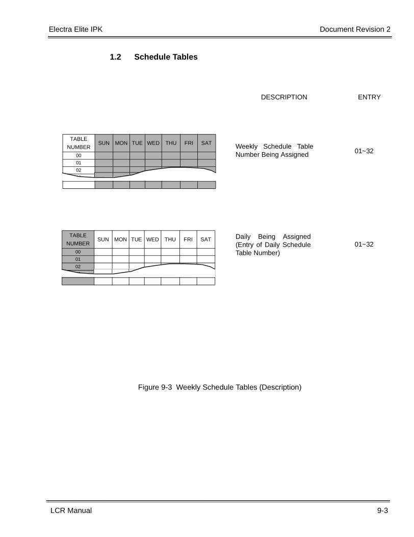
Electra Elite IPK Document Revision 2
LCR Manual 9-3
___________________________________________________________________________________
___________________________________________________________________________________
1.2 Schedule Tables
Figure 9-3 Weekly Schedule Tables (Description)
TABLE NUMBER
SUN MON TUE WED THU FRI SAT
00
01
02
03
Weekly Schedule TableNumber Being Assigned 01~32
Daily Being Assigned(Entry of Daily ScheduleTable Number)
01~32TABLE
NUMBERSUN MON TUE WED THU FRI SAT
00
01
02
03
DESCRIPTION ENTRY
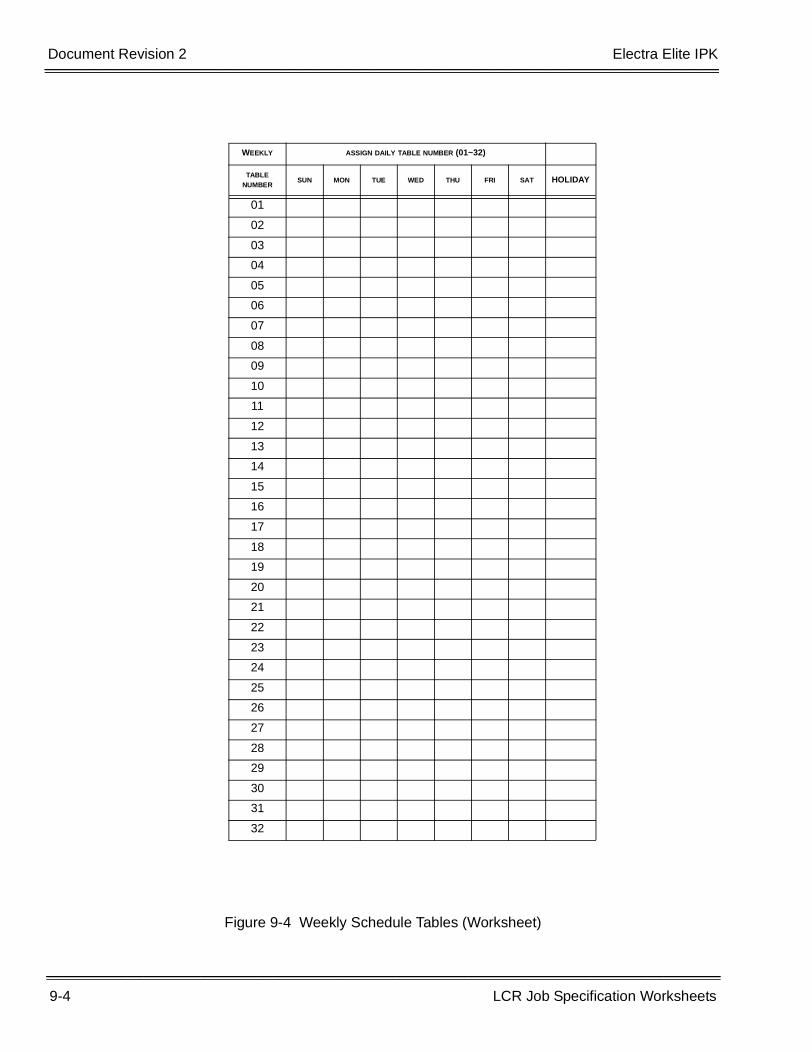
9-4 LCR Job Specification Worksheets
___________________________________________________________________________________
___________________________________________________________________________________Document Revision 2 Electra Elite IPK
Figure 9-4 Weekly Schedule Tables (Worksheet)
WEEKLY ASSIGN DAILY TABLE NUMBER (01~32)
TABLE NUMBER
SUN MON TUE WED THU FRI SAT HOLIDAY
01
02
03
04
05
06
07
08
09
10
11
12
13
14
15
16
17
18
19
20
21
22
23
24
25
26
27
28
29
30
31
32

Electra Elite IPK Document Revision 2
LCR Manual 9-5
___________________________________________________________________________________
___________________________________________________________________________________
Figure 9-5 Daily Schedule Tables (Description)
TABLE
01 02 03 04 05
01
02
03
32
TABLE
01 02 03 04 05
01
02
03
32
Daily Schedule TableNumber Being Assigned 01~32
Hourly Assignment(Entry of RouteAdvance Table)
01~64
DESCRIPTION ENTRY
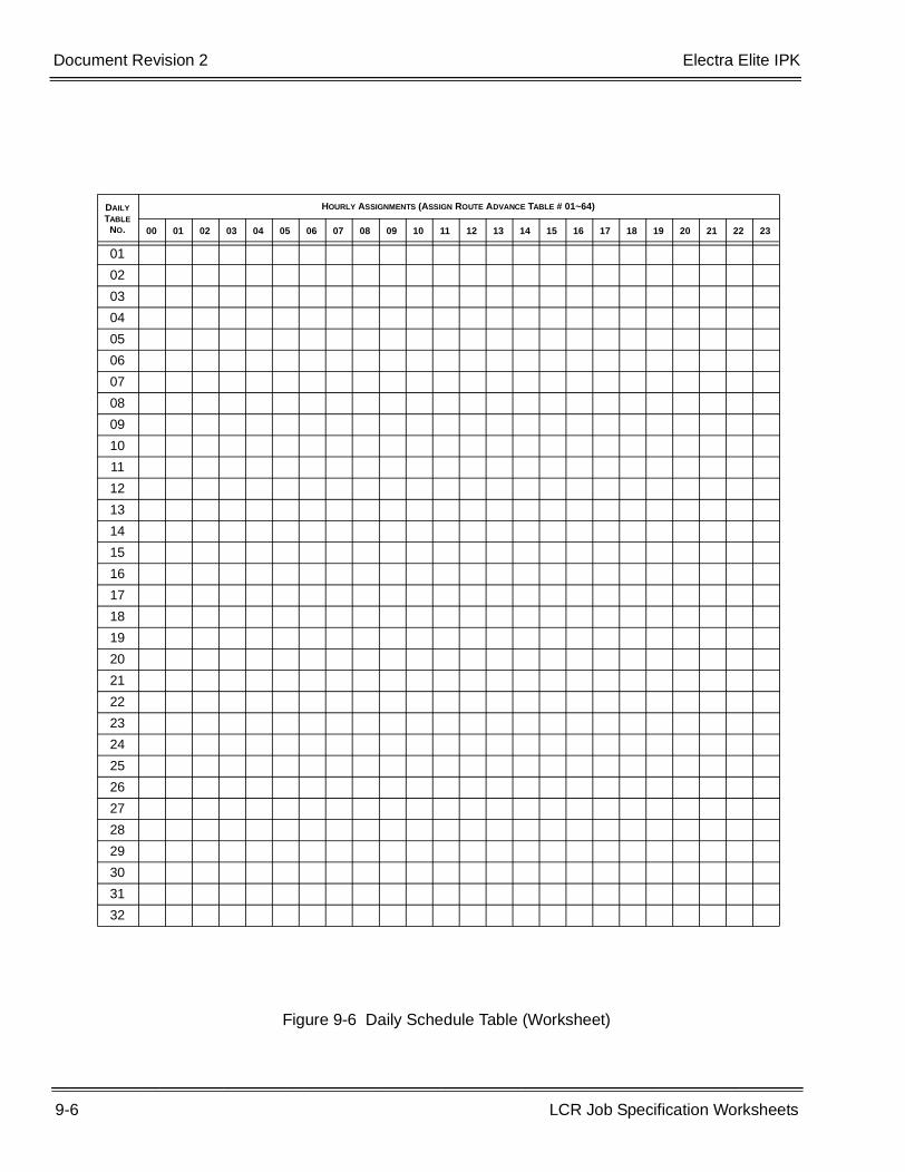
9-6 LCR Job Specification Worksheets
___________________________________________________________________________________
___________________________________________________________________________________Document Revision 2 Electra Elite IPK
Figure 9-6 Daily Schedule Table (Worksheet)
DAILY TABLE
NO.
HOURLY ASSIGNMENTS (ASSIGN ROUTE ADVANCE TABLE # 01~64)
00 01 02 03 04 05 06 07 08 09 10 11 12 13 14 15 16 17 18 19 20 21 22 23
01
02
03
04
05
06
07
08
09
10
11
12
13
14
15
16
17
18
19
20
21
22
23
24
25
26
27
28
29
30
31
32
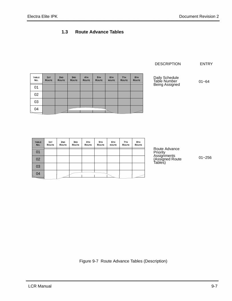
Electra Elite IPK Document Revision 2
LCR Manual 9-7
___________________________________________________________________________________
___________________________________________________________________________________
1.3 Route Advance Tables
Figure 9-7 Route Advance Tables (Description)
TABLE NO.
1ST ROUTE
2ND ROUTE
3RD ROUTE
4TH ROUTE
5TH ROUTE
6TH ROUTE
7TH ROUTE
8TH ROUTE
01
02
03
04
TABLE NO.
1ST ROUTE
2ND ROUTE
3RD ROUTE
4TH ROUTE
5TH ROUTE
6TH ROUTE
7TH ROUTE
8TH ROUTE
01
02
03
04
Daily Schedule Table Number Being Assigned
01~64
Route Advance Priority Assignments (Assigned Route Tables)
01~256
DESCRIPTION ENTRY
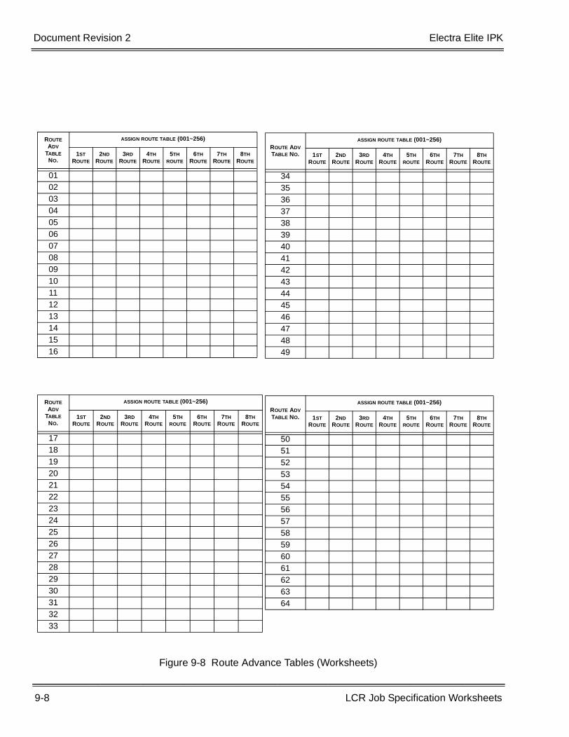
9-8 LCR Job Specification Worksheets
___________________________________________________________________________________
___________________________________________________________________________________Document Revision 2 Electra Elite IPK
Figure 9-8 Route Advance Tables (Worksheets)
ROUTE ADV
TABLE NO.
ASSIGN ROUTE TABLE (001~256)
1ST ROUTE
2ND ROUTE
3RD ROUTE
4TH ROUTE
5TH ROUTE
6TH ROUTE
7TH ROUTE
8TH ROUTE
01020304050607080910111213141516
ROUTE ADV
TABLE NO.
ASSIGN ROUTE TABLE (001~256)
1ST ROUTE
2ND ROUTE
3RD ROUTE
4TH ROUTE
5TH ROUTE
6TH ROUTE
7TH ROUTE
8TH ROUTE
1718192021222324252627282930313233
ROUTE ADV TABLE NO.
ASSIGN ROUTE TABLE (001~256)
1ST ROUTE
2ND ROUTE
3RD ROUTE
4TH ROUTE
5TH ROUTE
6TH ROUTE
7TH ROUTE
8TH ROUTE
34353637383940414243444546474849
ROUTE ADV TABLE NO.
ASSIGN ROUTE TABLE (001~256)
1ST ROUTE
2ND ROUTE
3RD ROUTE
4TH ROUTE
5TH ROUTE
6TH ROUTE
7TH ROUTE
8TH ROUTE
505152535455565758596061626364
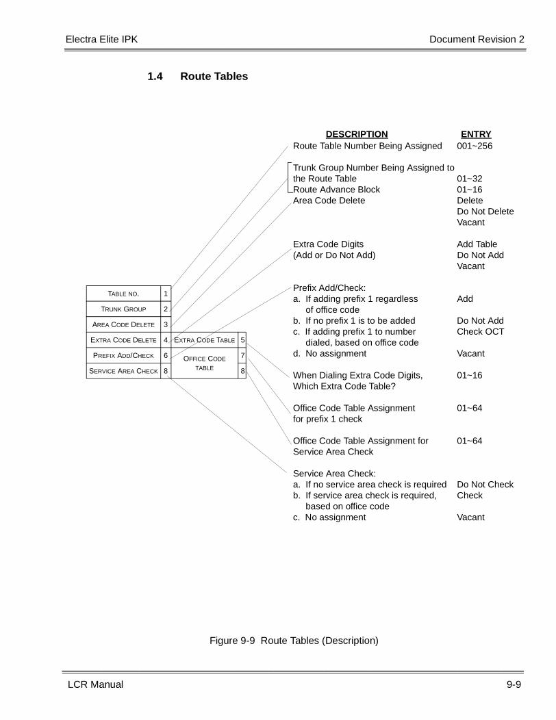
Electra Elite IPK Document Revision 2
LCR Manual 9-9
___________________________________________________________________________________
___________________________________________________________________________________
1.4 Route Tables
Figure 9-9 Route Tables (Description)
DESCRIPTION ENTRYRoute Table Number Being Assigned 001~256
Trunk Group Number Being Assigned to the Route Table 01~32Route Advance Block 01~16Area Code Delete Delete
Do Not DeleteVacant
Extra Code Digits Add Table(Add or Do Not Add) Do Not Add
Vacant
Prefix Add/Check:a. If adding prefix 1 regardless Add of office codeb. If no prefix 1 is to be added Do Not Addc. If adding prefix 1 to number Check OCT dialed, based on office coded. No assignment Vacant
When Dialing Extra Code Digits, 01~16Which Extra Code Table?
Office Code Table Assignment 01~64for prefix 1 check
Office Code Table Assignment for 01~64Service Area Check
Service Area Check:a. If no service area check is required Do Not Checkb. If service area check is required, Check based on office codec. No assignment Vacant
TABLE NO. 1
TRUNK GROUP 2
AREA CODE DELETE 3
EXTRA CODE DELETE 4 EXTRA CODE TABLE 5
PREFIX ADD/CHECK 6 OFFICE CODE TABLE
7
SERVICE AREA CHECK 8 8
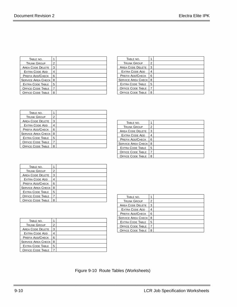
9-10 LCR Job Specification Worksheets
___________________________________________________________________________________
___________________________________________________________________________________Document Revision 2 Electra Elite IPK
Figure 9-10 Route Tables (Worksheets)
TABLE NO. 1TRUNK GROUP 2
AREA CODE DELETE 3EXTRA CODE ADD 4
PREFIX ADD/CHECK 6SERVICE AREA CHECK 8EXTRA CODE TABLE 5OFFICE CODE TABLE 7OFFICE CODE TABLE 8
TABLE NO. 1TRUNK GROUP 2
AREA CODE DELETE 3EXTRA CODE ADD 4
PREFIX ADD/CHECK 6SERVICE AREA CHECK 8EXTRA CODE TABLE 5OFFICE CODE TABLE 7OFFICE CODE TABLE 8
TABLE NO. 1TRUNK GROUP 2
AREA CODE DELETE 3EXTRA CODE ADD 4
PREFIX ADD/CHECK 6SERVICE AREA CHECK 8EXTRA CODE TABLE 5OFFICE CODE TABLE 7OFFICE CODE TABLE 8
TABLE NO. 1TRUNK GROUP 2
AREA CODE DELETE 3EXTRA CODE ADD 4
PREFIX ADD/CHECK 6SERVICE AREA CHECK 8EXTRA CODE TABLE 5OFFICE CODE TABLE 7
TABLE NO. 1TRUNK GROUP 2
AREA CODE DELETE 3EXTRA CODE ADD 4
PREFIX ADD/CHECK 6SERVICE AREA CHECK 8EXTRA CODE TABLE 5OFFICE CODE TABLE 7OFFICE CODE TABLE 8
TABLE NO. 1TRUNK GROUP 2
AREA CODE DELETE 3EXTRA CODE ADD 4
PREFIX ADD/CHECK 6SERVICE AREA CHECK 8EXTRA CODE TABLE 5OFFICE CODE TABLE 7OFFICE CODE TABLE 8
TABLE NO. 1TRUNK GROUP 2
AREA CODE DELETE 3EXTRA CODE ADD 4
PREFIX ADD/CHECK 6SERVICE AREA CHECK 8EXTRA CODE TABLE 5OFFICE CODE TABLE 7OFFICE CODE TABLE 8
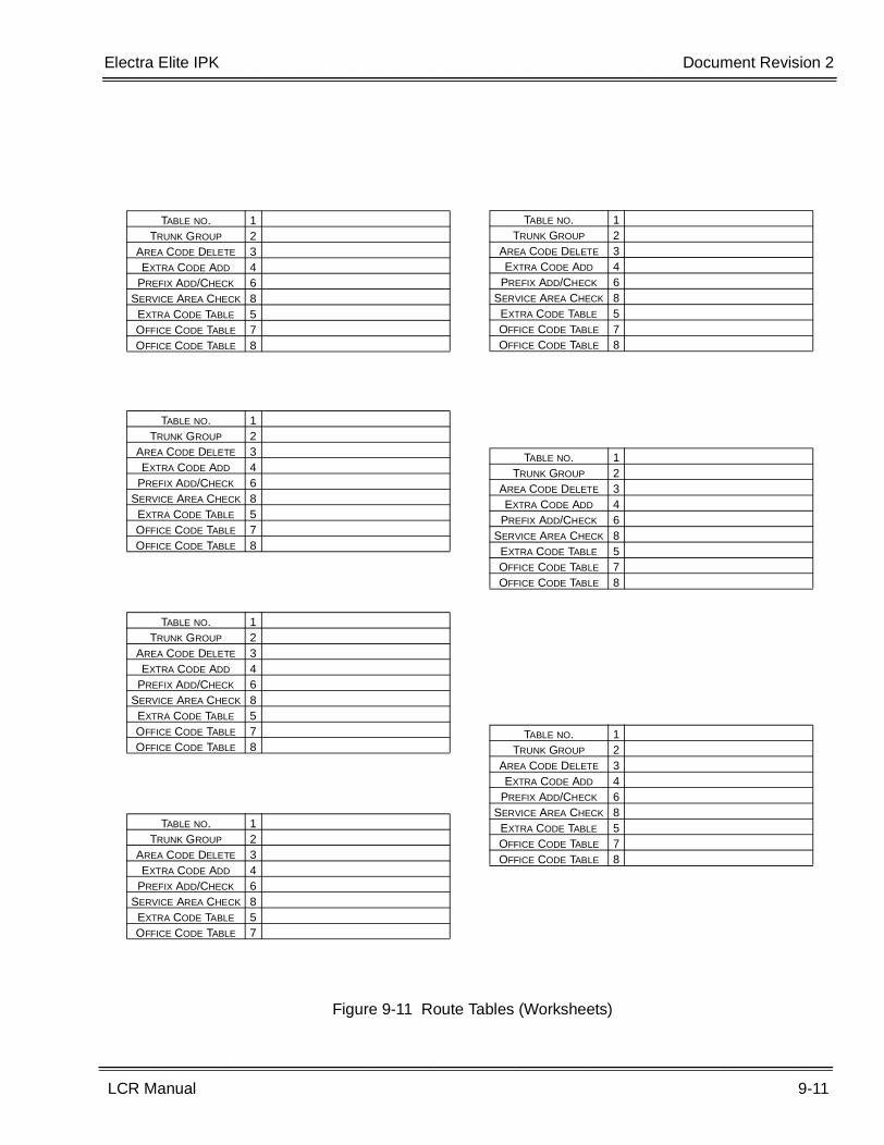
Electra Elite IPK Document Revision 2
LCR Manual 9-11
___________________________________________________________________________________
___________________________________________________________________________________
Figure 9-11 Route Tables (Worksheets)
TABLE NO. 1TRUNK GROUP 2
AREA CODE DELETE 3EXTRA CODE ADD 4
PREFIX ADD/CHECK 6SERVICE AREA CHECK 8EXTRA CODE TABLE 5OFFICE CODE TABLE 7OFFICE CODE TABLE 8
TABLE NO. 1TRUNK GROUP 2
AREA CODE DELETE 3EXTRA CODE ADD 4
PREFIX ADD/CHECK 6SERVICE AREA CHECK 8EXTRA CODE TABLE 5OFFICE CODE TABLE 7OFFICE CODE TABLE 8
TABLE NO. 1TRUNK GROUP 2
AREA CODE DELETE 3EXTRA CODE ADD 4
PREFIX ADD/CHECK 6SERVICE AREA CHECK 8EXTRA CODE TABLE 5OFFICE CODE TABLE 7OFFICE CODE TABLE 8
TABLE NO. 1TRUNK GROUP 2
AREA CODE DELETE 3EXTRA CODE ADD 4
PREFIX ADD/CHECK 6SERVICE AREA CHECK 8EXTRA CODE TABLE 5OFFICE CODE TABLE 7
TABLE NO. 1TRUNK GROUP 2
AREA CODE DELETE 3EXTRA CODE ADD 4
PREFIX ADD/CHECK 6SERVICE AREA CHECK 8EXTRA CODE TABLE 5OFFICE CODE TABLE 7OFFICE CODE TABLE 8
TABLE NO. 1TRUNK GROUP 2
AREA CODE DELETE 3EXTRA CODE ADD 4
PREFIX ADD/CHECK 6SERVICE AREA CHECK 8EXTRA CODE TABLE 5OFFICE CODE TABLE 7OFFICE CODE TABLE 8
TABLE NO. 1TRUNK GROUP 2
AREA CODE DELETE 3EXTRA CODE ADD 4
PREFIX ADD/CHECK 6SERVICE AREA CHECK 8EXTRA CODE TABLE 5OFFICE CODE TABLE 7OFFICE CODE TABLE 8
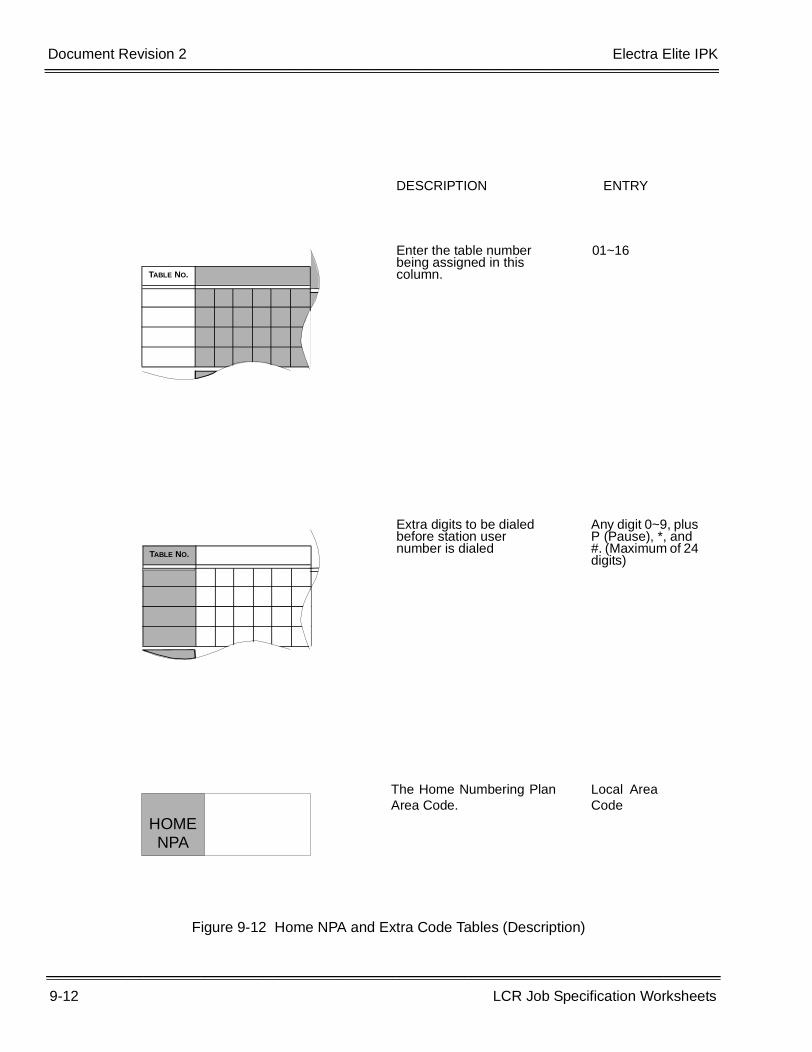
9-12 LCR Job Specification Worksheets
___________________________________________________________________________________
___________________________________________________________________________________Document Revision 2 Electra Elite IPK
Figure 9-12 Home NPA and Extra Code Tables (Description)
TABLE NO.
TABLE NO.
HOME NPA
DESCRIPTION ENTRY
Enter the table number being assigned in this column.
01~16
Extra digits to be dialed before station user number is dialed
Any digit 0~9, plus P (Pause), *, and #. (Maximum of 24 digits)
The Home Numbering PlanArea Code.
Local AreaCode
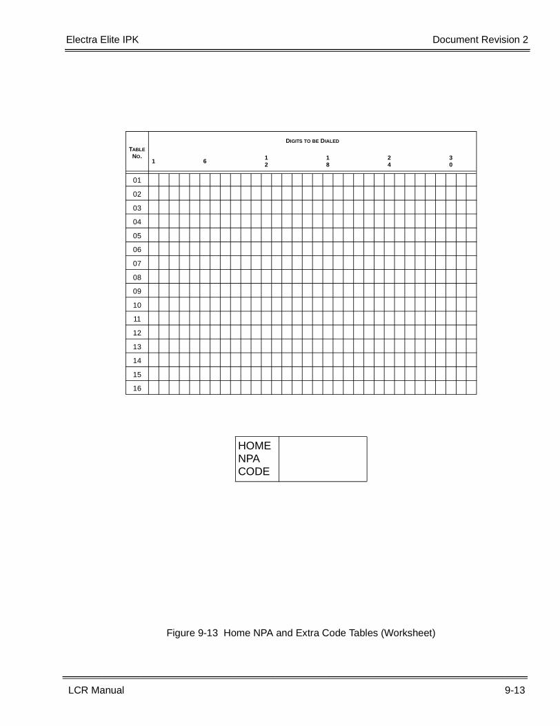
Electra Elite IPK Document Revision 2
LCR Manual 9-13
___________________________________________________________________________________
___________________________________________________________________________________
Figure 9-13 Home NPA and Extra Code Tables (Worksheet)
TABLE NO.
DIGITS TO BE DIALED
1 6 12
18
24
30
01
02
03
04
05
06
07
08
09
10
11
12
13
14
15
16
HOME NPA CODE
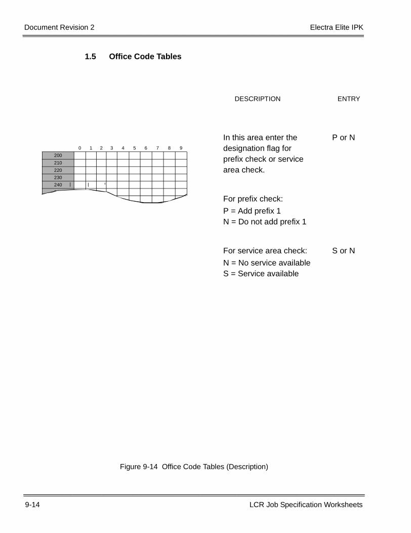
9-14 LCR Job Specification Worksheets
___________________________________________________________________________________
___________________________________________________________________________________Document Revision 2 Electra Elite IPK
1.5 Office Code Tables
Figure 9-14 Office Code Tables (Description)
0 1 2 3 4 5 6 7 8 9
200
210
220
230
240
250
In this area enter the P or Ndesignation flag forprefix check or servicearea check.
For prefix check:
P = Add prefix 1N = Do not add prefix 1
For service area check: S or N
N = No service availableS = Service available
DESCRIPTION ENTRY
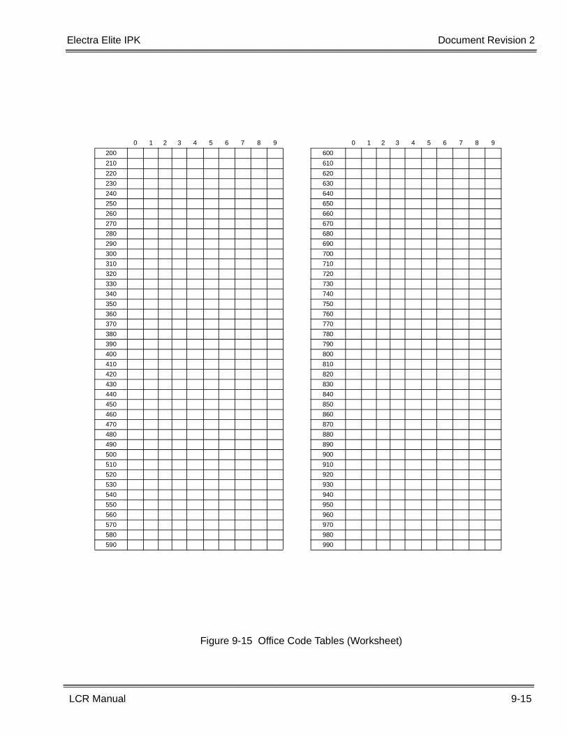
Electra Elite IPK Document Revision 2
LCR Manual 9-15
___________________________________________________________________________________
___________________________________________________________________________________
Figure 9-15 Office Code Tables (Worksheet)
0 1 2 3 4 5 6 7 8 9
200
210
220
230
240
250
260
270
280
290
300
310
320
330
340
350
360
370
380
390
400
410
420
430
440
450
460
470
480
490
500
510
520
530
540
550
560
570
580
590
0 1 2 3 4 5 6 7 8 9
600
610
620
630
640
650
660
670
680
690
700
710
720
730
740
750
760
770
780
790
800
810
820
830
840
850
860
870
880
890
900
910
920
930
940
950
960
970
980
990
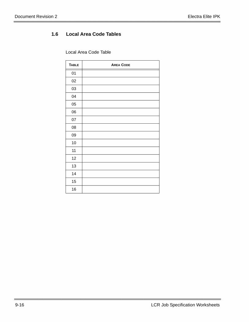
9-16 LCR Job Specification Worksheets
___________________________________________________________________________________
___________________________________________________________________________________Document Revision 2 Electra Elite IPK
1.6 Local Area Code Tables
Local Area Code Table
TABLE AREA CODE
01
02
03
04
05
06
07
08
09
10
11
12
13
14
15
16
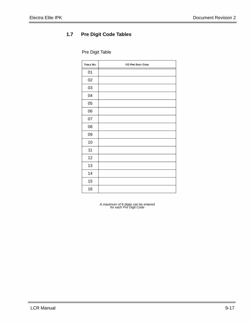
Electra Elite IPK Document Revision 2
LCR Manual 9-17
___________________________________________________________________________________
___________________________________________________________________________________
1.7 Pre Digit Code Tables
Pre Digit Table
TABLE NO. CO PRE DIGIT CODE
01
02
03
04
05
06
07
08
09
10
11
12
13
14
15
16
A maximum of 8 digits can be entered for each Pre Digit Code
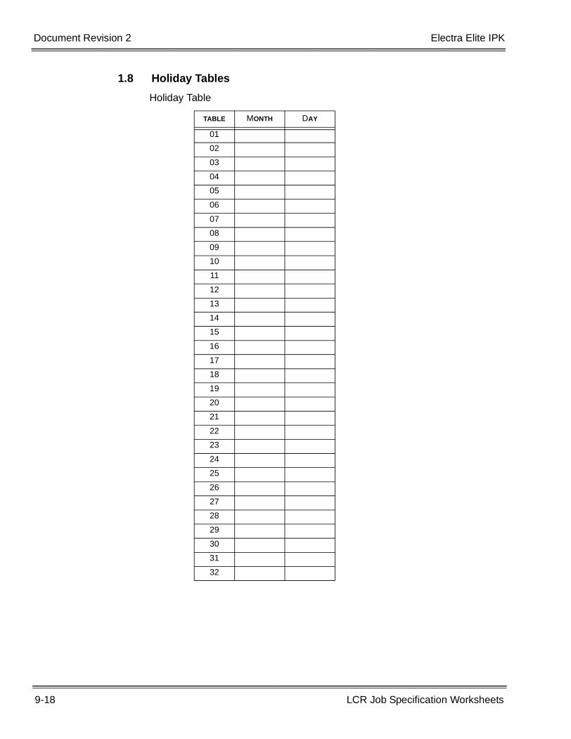
9-18 LCR Job Specification Worksheets
___________________________________________________________________________________
___________________________________________________________________________________Document Revision 2 Electra Elite IPK
1.8 Holiday Tables
Holiday Table
TABLE MONTH DAY
01
02
03
04
05
06
07
08
09
10
11
12
13
14
15
16
17
18
19
20
21
22
23
24
25
26
27
28
29
30
31
32
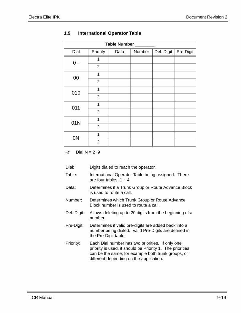
Electra Elite IPK Document Revision 2
LCR Manual 9-19
___________________________________________________________________________________
___________________________________________________________________________________
1.9 International Operator Table
Table Number ________
Dial Priority Data Number Del. Digit Pre-Digit
0 -1
2
001
2
0101
2
0111
2
01N1
2
0N1
2
� Dial N = 2~9
Dial: Digits dialed to reach the operator.
Table: International Operator Table being assigned. There are four tables, 1 ~ 4.
Data: Determines if a Trunk Group or Route Advance Block is used to route a call.
Number: Determines which Trunk Group or Route Advance Block number is used to route a call.
Del. Digit: Allows deleting up to 20 digits from the beginning of a number.
Pre-Digit: Determines if valid pre-digits are added back into a number being dialed. Valid Pre-Digits are defined in the Pre-Digit table.
Priority: Each Dial number has two priorities. If only one priority is used, it should be Priority 1. The priorities can be the same, for example both trunk groups, or different depending on the application.
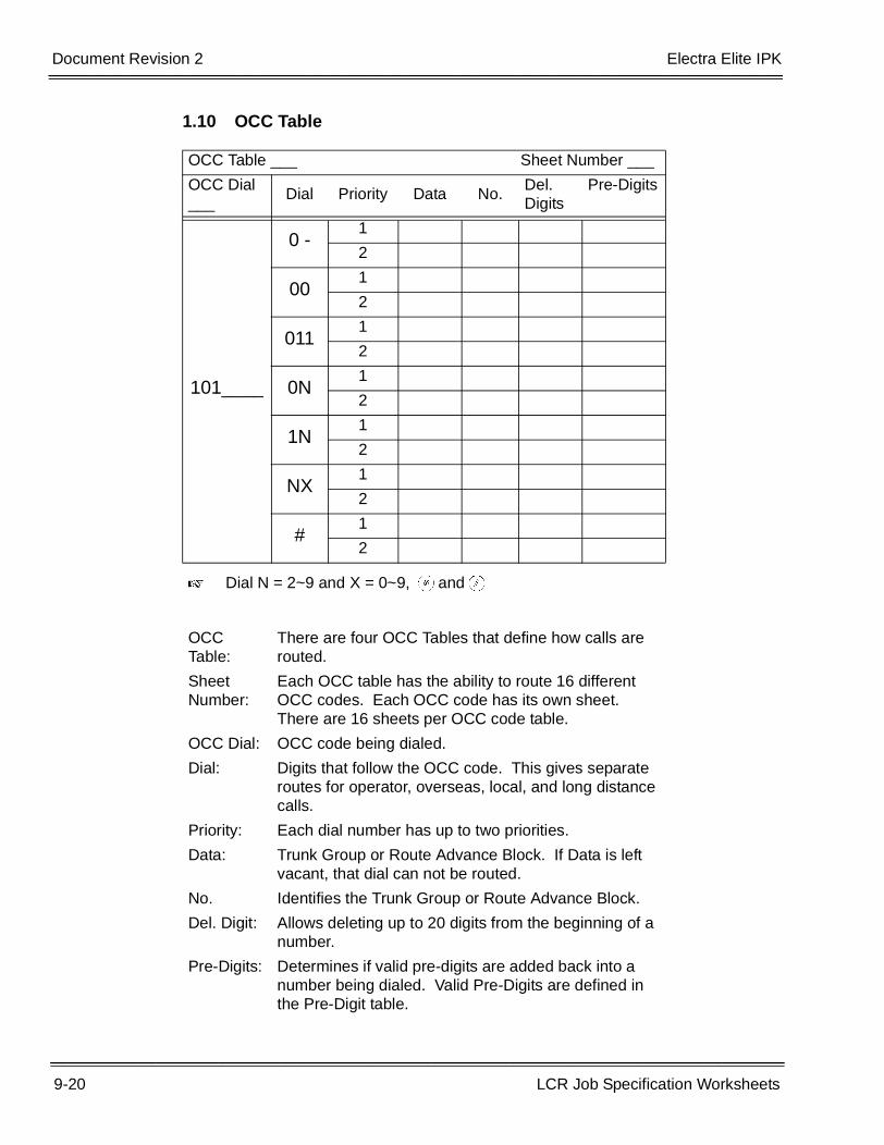
9-20 LCR Job Specification Worksheets
___________________________________________________________________________________
___________________________________________________________________________________Document Revision 2 Electra Elite IPK
1.10 OCC Table
OCC Table ___ Sheet Number ___
OCC Dial ___
Dial Priority Data No.Del. Digits
Pre-Digits
101____
0 -1
2
001
2
0111
2
0N1
2
1N1
2
NX1
2
#1
2
� Dial N = 2~9 and X = 0~9, JandL
OCC Table:
There are four OCC Tables that define how calls are routed.
Sheet Number:
Each OCC table has the ability to route 16 different OCC codes. Each OCC code has its own sheet. There are 16 sheets per OCC code table.
OCC Dial: OCC code being dialed.
Dial: Digits that follow the OCC code. This gives separate routes for operator, overseas, local, and long distance calls.
Priority: Each dial number has up to two priorities.
Data: Trunk Group or Route Advance Block. If Data is left vacant, that dial can not be routed.
No. Identifies the Trunk Group or Route Advance Block.
Del. Digit: Allows deleting up to 20 digits from the beginning of a number.
Pre-Digits: Determines if valid pre-digits are added back into a number being dialed. Valid Pre-Digits are defined in the Pre-Digit table.
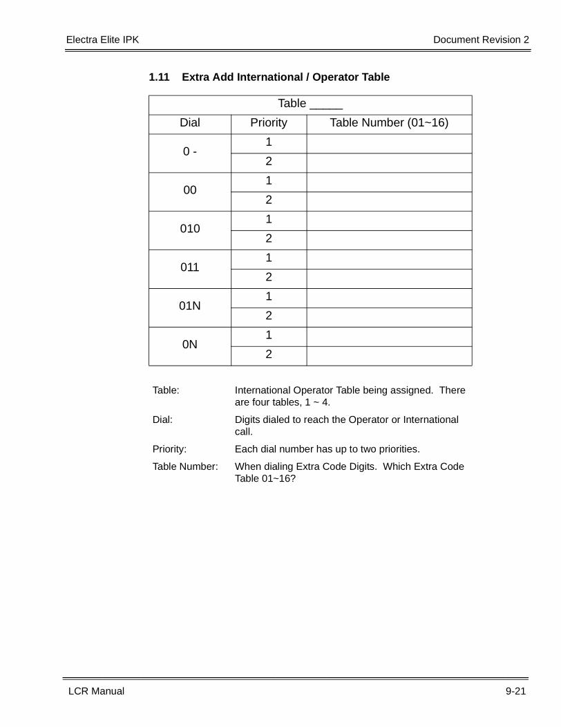
Electra Elite IPK Document Revision 2
LCR Manual 9-21
___________________________________________________________________________________
___________________________________________________________________________________
1.11 Extra Add International / Operator Table
Table _____
Dial Priority Table Number (01~16)
0 -1
2
001
2
0101
2
0111
2
01N1
2
0N1
2
Table: International Operator Table being assigned. There are four tables, 1 ~ 4.
Dial: Digits dialed to reach the Operator or International call.
Priority: Each dial number has up to two priorities.
Table Number: When dialing Extra Code Digits. Which Extra Code Table 01~16?
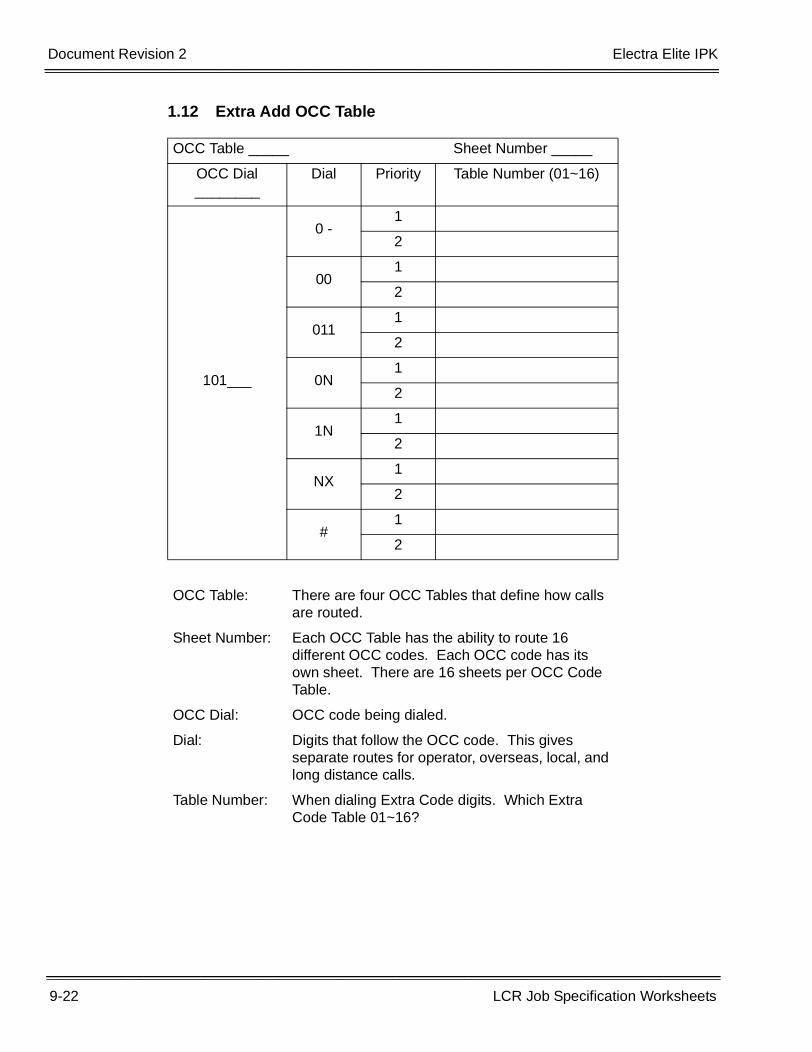
9-22 LCR Job Specification Worksheets
___________________________________________________________________________________
___________________________________________________________________________________Document Revision 2 Electra Elite IPK
1.12 Extra Add OCC Table
OCC Table _____ Sheet Number _____
OCC Dial________
Dial Priority Table Number (01~16)
0 -1
2
001
2
0111
2
101___ 0N1
2
1N1
2
NX1
2
#1
2
OCC Table: There are four OCC Tables that define how calls are routed.
Sheet Number: Each OCC Table has the ability to route 16 different OCC codes. Each OCC code has its own sheet. There are 16 sheets per OCC Code Table.
OCC Dial: OCC code being dialed.
Dial: Digits that follow the OCC code. This gives separate routes for operator, overseas, local, and long distance calls.
Table Number: When dialing Extra Code digits. Which Extra Code Table 01~16?
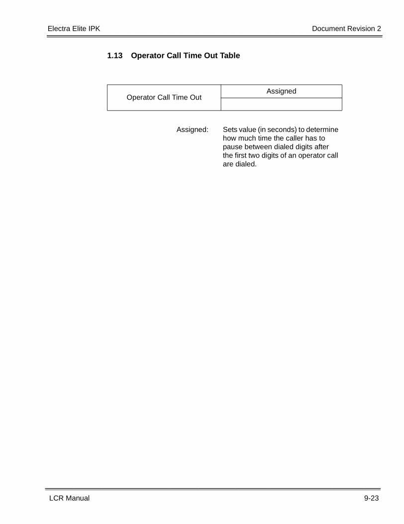
Electra Elite IPK Document Revision 2
LCR Manual 9-23
___________________________________________________________________________________
___________________________________________________________________________________
1.13 Operator Call Time Out Table
Operator Call Time OutAssigned
Assigned: Sets value (in seconds) to determine how much time the caller has to pause between dialed digits after the first two digits of an operator call are dialed.
9-24 LCR Job Specification Worksheets
___________________________________________________________________________________
___________________________________________________________________________________Document Revision 2 Electra Elite IPK
THIS PAGE INTENTIONALLY LEFT BLANK

LEAST COST ROUTING MANUAL
NEC America, Inc.
Document Revision 2
and