Embed Size (px)
Citation preview
NASA CR-
FINAL REPORT
ADVANCED LIFE SYSTEMS HARDWARE
DEVELOPMENT FOR FUTURE MISSIONS
Contract NAS 9-13603
Submitted to
NATIONAL AERONAUTICS AND SPACE ADMINISTRATION
Lyndon B. Johnson Space CenterHouston, Texas
By
TELECARE, INC.8575 Mosley Road
Houston, Texas 77034
fe&FfH A-Rf WsA'RfE- -4i*»^L@|KftfB)Hf'- - ^Fiaai -fteipS'-r't •(It'e^Ga'te- -'i65 p" ^ • €'§i&L
January, 1975
ELECARE8575 MOSLEY ROAD. HOUSTON, TEXAS 77034 • (713) 944-5753
https://ntrs.nasa.gov/search.jsp?R=19750009893 2018-07-17T13:13:47+00:00Z
FINAL REPORT
ADVANCED LIFE SYSTEMS HARDWARE
DEVELOPMENT FOR.FUTURE MISSIONS
Contract-MAS 9-13603
Submitted to
NATIONAL AERONAUTICS AND SPACE ADMINISTRATION
Lyndon B. Johnson Space Center
Houston, Texas
By
TELECARE, INC.
8575 Mosley Road
Houston, Texas 77034
January,, -1975
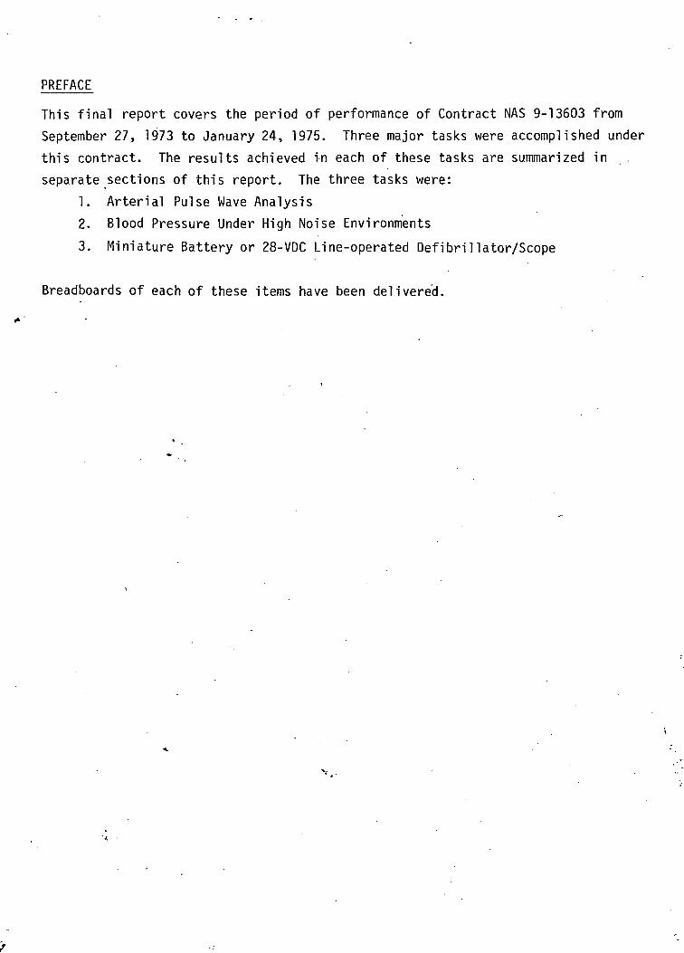
PREFACE
This final report covers the period of performance of Contract NAS 9-13603 from
September 27, 1973 to January 24, 1975. Three major tasks were accomplished under
this contract. The results achieved in each of these tasks are summarized in .
separate sections of this report. The three tasks were:
1. Arterial Pulse Wave Analysis
2. Blood Pressure Under High Noise Environments
3. Miniature Battery or 28-VDC Line-operated Defibrillator/Scope
Breadboards of each of these items have been delivered.
TECHNICAL REPORT
ARTERIAL PULSE WAVE ANALYSIS
ARTERIAL PULSE WAVE ANALYSIS
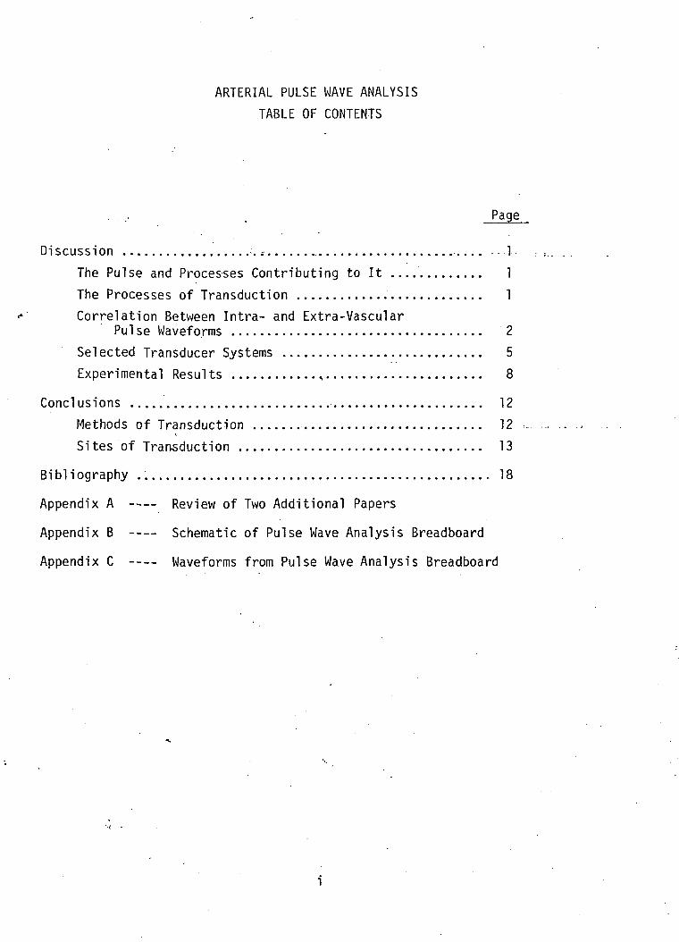
TABLE OF CONTENTS
- • -• . . Page
Discussion •..- — . - 1
The Pulse and Processes Contributing to It 1
The Processes of Transduction 1
Correlation Between Intra- and Extra-VascularPul se Waveforms 2
Selected Transducer Systems 5
Experimental Results % 8
Conclusions 12
Methods of Transduction 12
Sites of Traasduction 13
Bi bli ography 18
Appendix A Review of Two Additional Papers
Appendix B Schematic of Pulse Wave Analysis Breadboard
Appendix C Waveforms from Pulse Wave Analysis Breadboard

A REVIEW OF PULSE PRESSURE
WAVEFORM MEASUREMENT
DISCUSSION
•The Pulse and Processes Contributing to It
• The palpable pulse is a consequence of a regional volume and pressure changing
process within the vascular system. The two processes are not in phase with
the volume pulse generally leading the pressure pulse in the order of 0. 005
seconds. An examination of the pulse formation in an externalized vessel
suggests that the vessel does-not behave as a simple visco-elastic tube. These
findings show that a regional increase in pressure is preceded by a regional
increase in volume. Concomitant with the radial motion of the vessel wall,
there is a longitudinal motion which may be quite large in relation to the radial1 2motion. ' It is usually this longitudinal motion that results in a straightening
of the vessel: a motion that contributes in a major fashion to the palpable2
pulse in the radial artery. While a shortening of the vessel with pulse
propagation is the usual observation, a lengthening of a vessel with pulse1
propagation may also occur.
As the pulse wave (volume and pressure) propagates along the vascular system,3-5the wave changes shape. As a consequence of this change in shape,
peripheral pulse waveforms may not always reflect what is occurring in the
central vascular system. For example, during periods of vascular stenosis
in a peripheral artery, a flow into limb segments distal to the stenosis may•*.
be adequate although a palpable pulse may not be present.
The Processes of Transduction
Pressure-pulse waveform transducers are sensitive either to the pressure• /.
present at the vessel wall or to the volume of blood filling a region of tissue.
The pressure determination requires the transducer to contact the vessel
wall through the intervening tissue. Some deformation of the vessel wall is
required for such a measurement which can, in turn, change how the wall
responds to the pressure. Regardless of how the pressure is transduced,
the transducer must be in intimate contact with the vessel wall iri order to
sense the intra-vascular pressures exerted on the wall. Since the transducer,
is responding to a hydraulic process, it is often optimally coupled to the
vessel in order to obtain the best reproduction of intra-vascular pressures
as possible. ' In other words, it must successfully communicate with the
vessel wall through the intervening tissue and "float" on the vessel without
^distorting the waveform. This approach obviously necessitates a transducer
designed specifically for each size of vessel to be examined. Further, the
transducer must then be placed correctly on the vessel.
Correlation Between Intra- and Extra-Vascular Pulse Waveforms
.. .When >.dis cuss ing the pulse waveform, , it is. important to specify where in.the
vascular system the, pulses are taken. This is a consequence of the change,
in shape that occurs as the pulse is propagated through the arterial system.
A further complication occurs with the application of the sensing transducer
which'-has the potential to-distort the measured waveform -when the transducer
is in intimate contact with the vessel.
The most uncomplicated method of obtaining pulse waveforms is using a
pressure cuff as a sensing device. Dontas used such a device to examine - -
some of the properties of the cuff in sensing the pulse pressure waveform.
Simultaneously, an intra-arterial catheter was placed under the region of
measurement for the cuff. Several sites on the arm and the carotid artery
were examined in this fashion. - -- - - - - . • ; . . . . •
The pressure waveform was found to increase in amplitude when the counter*• 10pressure exerted by the cuff increased. The optimum intra-cuff pressure
x.
--for-the best- correlation between-intra^and extra-arterial pressure's-was
determined to be 40 mm Hg. Cuff pressures exceeding diastolic pressure
were observed to transform carotid and upper brachial artery waveforms
-2-
to more peripheral-vessel-looking waveforms. With the use of vasoactive
agents, Dontas observed that external pulses do not reflect intra-arterial
pressures when the vessel wall tension changes. However, the extra-
arterial pulses best resembled intra-arterial pulses when the cuff pressure
•was kept slightly below the diastolic pressure.
Robinson examined the relationship between the carotid extra-vascular
-waveform sensed with a pressure cuff, and its intra-vascular shape in patients
. with cardiac abnormalities. While the extra- and intra-vascular recordings
were not identical and suffered considerable variation from case to case, the
•" way the waveforms differed was almost always the same. High-frequency
components of the intra-vascular recording were attenuated in the extra-
vascular recordings, but not lost entirely. Robinson further observed that
the brachial artery often showed intra-'vascular pressure differences from
the carotid internal and external recordings that would preclude some
-- diagnoses from the radial -artery waveform; and he concluded that carotid
artery pulse waveforms contain information on aortic pressures that is lost,
in brachial artery measurements.
Impedance plethysmography has received'a great deal of attention concerning
the relationship between extra-vascular impedance and intra-vascular
pressure recordings. ' ' The changes in pulse wave contour associated
with segments of the human lower limb have been closely examined. These
' changes in shape follow the kinds of changes observed for intra-vascular-3 4
pressure waveform mappings. ' The primary premise is that impedance
plethysmographic techniques are measuring the tissue volume-impedance
changes between sensing electrodes due to blood flow into the sensed region.
~ In" spite of this supposition, the1 impedance waveform is observed to be
highly correlated with the intra-vascular pressure waveform. ' Indeed,
Mohammad and Coulter have determined by Fourier analysis that the harmonic
content for intra-vascular pressure waveforms and extra-vascular impedance12
waveforms is nearly the same. 'However, a critical analysis of impedance
plethysmographic techniques suggests that the entity sensed by the impedance14
plethysmograph may not be tissue volume impedance at all. Rather, Hill
-3-

et al. have stated that skin-electrode interface, straingauge-type transduction14
may be occurring. This type of transduction would explain the close
correspondence observed between intra- and extra- vascular recordings.
Since mechanical straingauges are manufactured that can be calibrated
better than impedance plethysmographs, Hill et al suggested that a standard
straingauge would be a better choice than the impedence plethysmograph for .,. 14
extra-vascular recordings.
Heyman has carefully examined intra- and extra-vascular recordings of the
pulse pressure with an externally positioned piezoelectric crystal. Heyman
f pbserved in both man and dog that extra-vascular pressure waveforms
.occurred .before the intra-vas.cular pressure recordings in the majority (66%)
of the observed subjects. The remaining subjects (34%) produced intra- and
extra-vascular recordings close in shape, phase, and amplitude. With the
occurrence of vasoactivity, the observed differences in the two recordings
. .increased with intra- and. extra-vas.cular-waveforms changing- simultaneously^ -
but in opposite directions. These kinds of changes were noted in both
humans and dogs. These changes in the extra-arterial waveform with vaso-
activity observed by Heyman are similar to those observed by Dontas using
the pressure cuff.
While Heyman1 s crystal pickup device was rather elaborate, a simple crystal
system has been reported by Abbott and Hemsley which was produced from a
phonograph crystal pickup and showed-an excellent correspondence between* -
extra- and intra-vascular waveforms. However, Abbott and Hemsley did
not examine waveform changes with variations in vasomotor tone.
' Ghlebus--has reported-on the relationship between several extra-arterial pulse
measurement devices and intra-arterial pressure waveforms. One of
the devices functions in an unknown manner but the remaining were crystal•«.
microphones and photoelectric receivers. Chlebus found the bestv,
correspondence between intra—and extra-vascular recordings with the so called
"resonance electrosphygmometer, " the operation of which is unknown at this
time. Reasons for this ignorance will be explained later. However, sequential
-4-
readings with piezoelectric crystals and photoelectric systems showed a17
large variation in reading to reading for both devices. In many instances,
these variations were statistically significant and had little relation to intra-
vascular pressure recordings. Simultaneous photoelectric and piezoelectric
recordings were shown to differ significantly not only between one another but
with intra-arterial pressure recordings. The variations were found to be ., i
strongly influenced by the "loading" of the device to the vessel wall, that is,17
the pressure applied to the vesseLby the crystal or photoelectric receivers.
The resonance electrosphygmograph, however, is reported to measure vessel
wall displacement some four millimeters from the vessel and, thus, does
"not "load" the vessel wall.
It is evident from these studies that considerable differences between intra-
and extra-vascular recordings can arise from changes in vasomotor tone9and transducer application. Such changes may preclude definitive diagnoses
- in* some individuals'and-may-•fur-ther'-specify some of the measurement
strategy. - .
Selected Transducer Systems
' Of-the many systems available to determine the pulse waveform, only a few
show real promise for development into specifically useful devices. Most
of these devices are presently used clinically for evaluation of pulse wave-
forms obtained from various sites on the body. All are subject to the
•r problems inherent to any attempt to transduce waveforms by contact-with
vessels and surrounding tissue. Except for mechanical straingauges, none
of the devices allow for an absolute measurement. Thus, the measurements
remain largely qualitative in nature.
A primary system is simply a straingauge placed in contact -with a vessel
wall or with a digit and held in place with a circumferential strappingA— ft 1 ft *"
system. ' Reported experience with such devices show some potential
for calibration to absolute values. ' Qne could calibrate "by taking
systolic and diastolic pressures with a sphygmomanometer before using the
device to obtain waveforms. Some difficulties associated with straingauges
-5-
include positioning of the transducer on the vessel and coupling the signal
over to the transducer. ' This later problem has produced a number of
experimental devices that use a \vater chamber to couple to the vessel wall
and carefully designed "platens" that reliably transduce the pressure exerted -/_ o
on the vascular wall. While the transducer may be successfully coupled
to the vessel wall,. that coupling has a good potential for changing the entity .9being measured. This is not an easy problem to overcome and several
i good engineering attempts have been made to compensate for these/ _Q io on
deficiencies. ' ' The successes have not been excitingly great.
*•' Positioning the transducer will not be an easy problem to solve because a
j--.-"la-rge "-transducer doe s> not- couple -well to the vessel wall and a small one •• '
requires an exact positioning over the vessel wall. Deep lying vessels and
those with a poorly palpable pulse will'make this kind of transduction difficult
at best.
Piezoelectric microphones, like straingauges, can be obtained with considerable
"flatness" in the passband of measurement. Further, they can be cut to many
sizes, loaded, damped, shaped, and are very sensitive -when coupled into
modern high-gain, high-impedance amplifiers. Unfortunately, piezoelectric
devices lack any possibility of being calibrated in absolute values. There is
the further problem of loading the vessel being measured with the microphone17and distorting the measured waveform. However, in spite of these
limitations, the piezoelectric, contact microphone is commonly used to obtain
carotid artery pulses for diagnosis in cardiology. Along with the pressure24
waveform, and EGG and heart sounds are also recorded. Two major
manufactured devices used clinically are the Hewlett-Packard Pulse Wave
Pickup microphone'system-(Model 2105ID) and the Electronrcs for Medicine
contact microphone system (Models A161 and PS-IB). There are numerous
articles showing a developing analytical base for qualitative analysis of the*• 21-24 29
waveforms obtained with these crystal microphones. '
Interestingly, there has not developed a common or successful "loading"
technique for the use of these devices; and, since all are hand-held in
-6-
position, they are subject to the vibration and pressure judgements of the
person holding the device. Hand-held devices can be a source of noise, for
example, experience in ultrasound shows that a hand-held ultrasound
transducer becomes a major source of noise in many ultrasound techniques.
While the clinical use of a sensing cuff for carotid pressures is uncommon in,
the U. S. , the British have approached the cuff constructively and use it for
qualitative evaluation of pulse waveforms. ' Sensing of pulse waveforms
in the upper limbs with a cuff has been experimented with in our laboratory
in order to understand some of its limitations.
* * -•»
Another technique worthy of exploration.is ultrasound ranging. The basic
concept is simply one of ranging on a vessel wall to follow its motion.
It could be argued that this may be more a volume sensing process than a
pressure sensing process. The results of some experimentation with
. ultrasound will be presented in more detail later in the report.
Along with the more obvious techniques listed above is what may be called
a "mystery transducer. " Chlebus has presented a quantitative evaluation
of this device versus intra-vascular-pressure waveforms in a Western17
publication. However, the technical aspects of the device including its
means of transduction are still published only in Polish. The device is
called a "resonance electrosphymograph" and is purported to transduce the
-pulse waveform at a distance of four millimeters from the vessel wall. The
published correlative study suggested a good correspondence between the
transduced waveform and the intra-vascular waveform. The device is
worthy of some further investigation to determine the means of transduction
and its potential application to clinical measurements in the U. S; Evidently,
the device was designed and manufactured in Poland and knowledge of this
device has extended little beyond. Reports in Western journals suggest a-. 17 27
rather widespread clinical use of this device in Poland. ' Copies of the•*j
— Polish papers concerning the-basis of-ope ration for this device have "been
ordered and an interpreter located. While this will be of little value to the
present program, the potential applicability of such a device warrants some' f-_
scrutiny.
-7-
Experimental Results
A large number of experiments were conducted by Telecare, Inc. in order
to better understand some of the parameters associated with obtaining pulse
waveforms. Since many of these techniques are well established, the main
thrust of the experimentation was directed at the quality of the waveforms and
what variables are present in obtaining the waveform.
All the microphone and cuff displays and recordings \vere made with an
Electronics for Medicine, Model DR-8 recorder. Ultrasound techniques
were examined using an SKI Ekoline 20 and a Physionics Engineering, Inc.
.Somascope, Model TMA-2 in conjunction with the Electronics for Medicine
Model DR-8 recorder. . . . . . .
Since the pressure cuff -was the most simple approach, an adult size cuff
(15 cm wide) was used to detect pressure waveforms in the arms of three
subjects. The results were.generally the same as reported by Dontas.
There is a direct relationship between the intra-cuff pressures and the
magnitude of the recorded pressure waveform. The optimum waveforms
were consistently obtained with cuff pressures of 40 to 60 mm Hg. A
combination of the pressure cuff and the Hewlett-Packard microphone,
which was connected to the intra-cuff air volume, produced a system that
was sensitive to the cuff pressure for waveform amplitudes, but, unlike a
pressure straingauge, did not require re-zeroing for changes in intra-
cuff static pressures. The microphone proved to be quite sensitive when " • •'•• ••"•'
coupled to the pressure cuff and pressure waveforms were obtainable in
subjects in whom pressure waveforms were difficult to obtain by other
means.
The digit plethysmograph was also briefly examined in terms of its position
dependence and temperature dependent vasoactivity. Results indicated that*.
a cold subject simply did not produce a pulse waveform much larger than• > < • . .
muscle tremor-signals. While the weightlessness of space takes: away the
digit-heart level relationship as a variable, normal vasoactivity in the
digits produces wide variability in the size and shape of the transduced' /„
waveforms.
-8-
:. . » r .
Several microphones were examined \vhich were of the piezoelectric type.
The Hewlett-Packard and Electronics for Medicine microphones are routinely
used in cardiology for carotid artery waveforms and apexcardiography. Thus,
a rather broad experience background is available for microphones and their
application to cardiology. Included in the microphone examination was the
NASA type with a contact face 3. 9 centimeters in diameter. Some
experimentation with these devices showed them to be pressure sensitive,
with some waveform amplitude variations occurring with variation in applied
pressure. Clinically these devices are seldom held in position with anything
but the hand. There has not developed a standardized approach to minimizing
- these observed variations. This fact may help explain the relegation of pulse
- .waveformuanalysisito a minor role in cardiovascular diagnosis. - - . - . : ^ • - . . T . - . - J ^1 =
While ultrasound ranging is considered one of the techniques worthy of
exploration, it does not represent an "off-the-shelf" technology. Ultrasound
••- has been included because of the-technological explosion presently occurring
in ultrasound and its potential for utilization.
The signal is obtained by echo ranging off the vessel wall that is in motion
as-a consequence of the volume and-pressure changes within-the vessel. The
signal presentation was amplitude versus time: an "A mode" presentation.
The resulting signal was an amplitude varying signal rather than a time
displaced signal. This was a-some what unexpected result but-a-ft-er some -•
consideration of the arterial motion amplitude involved and the resolving28ability of ultrasound, the result is quite in line with the facts.
-Measurements o f radial a n d longitudinal vessel motion during-pulse wave • • • • • •
propagation support the notion that radial movement is very small in
peripheral arteries. If the equipment being used has a resolution of 1-2*" 28millimeters, then vessel motion less than this value will not be detected.
•»
However, a varying amplitude is detectable by two means: 1) some variation
in the acoustical impedances at the interface between the vessel wall and
either the,intra-or extra-vascular fluids, and 2) a change in vessel position
-9-
that increases the amount of acoustical energy scattered back to the
transducer.
A problem assuming major proportions in this technique is transducer
noise. The major source of noise is a consequence of using a hand-held device.
The vessel signal is further masked by signals coming from the transducer-
skin interface, and ringing of the crystal. Most of the vessels of interest
are close to the surface and standard clinical transducers focused at 10 and
15 centimeters are not optimal for this technique. One method of moving
the signal out of the noise is an"extension" made of water or Lucite which
would change the absolute positioning between the transducer and the vessel
- wall. -The results can be summarized- as follows. The technique: - 1) does -•
show a pulse related signal change, 2) does require a modification of
transducer configuration to shorter focal lengths and movement of the signal
out of the noise, 3) does require a coupling material consistent with
:contemporary- ultrasonic techniques, 4): does have a potential worth exploring, -
and 5) does require the development of new ultrasound technology or the
reapplication of existing technology to display the pulse events as a waveform.
Assuming some -improved technique -for displaying the information, the
question of what pulse events are being transduced still needs to be answered.
In order to provide a means of evaluating different techniques of transduction,
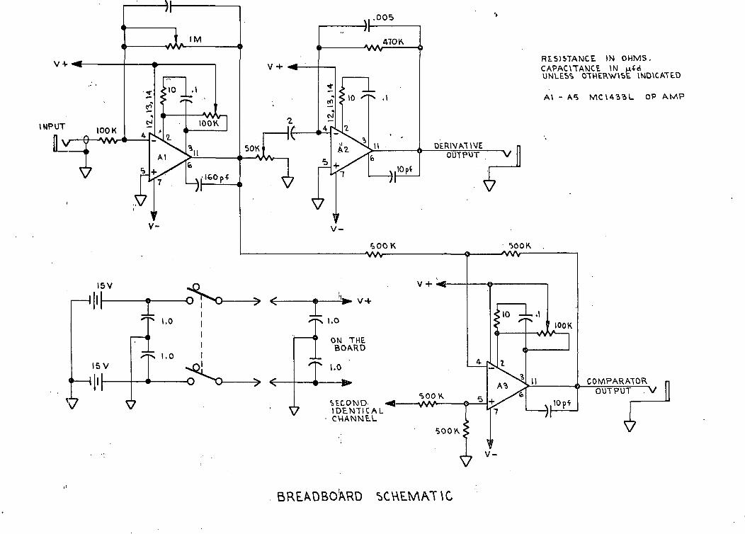
an analytical circuit was constructed. --This device was developed with -the •'
concept of examining waveforms for comparison as well as diagnostic
parameters. Mason, et al._ have presented good empirical data to support
the use of the first and second derivatives of pulse pressure waveforms in
is. - - Thus,- -the-bread-board circuit was designed as a-two^ehannel
input and derivatives of these inputs as outputs from the circuit. Dontas
and Cottas have demonstrated the analytical advantages of using a*• 13
differential amplifier as a comparator. In order to provide a scalar\'
comparison-technique between two -waveforms, a comparator was also "
incorporated into the bread board permitting a comparison of the two input
channels. .Because of severe time limitations, the circuit has not yet been
-10-

fully evaluated but will be delivered as a part of this contract for potential
use in any follow-on activity.
-11-
CONCLUSIONS
Methods of Transduction
Of the many devices and techniques available to obtain pulse waveforms,
none fall into a category of Optimum. All have drawbacks that prevent
definitive evaluations of pulse waveforms. Indeed, the system being measured
can present a number of changes that will defeat the measuring technique being
used. Results of comparisons between intra- and extra-vascular pressure
recordings suggest that changes in vasomotor tone and transducer-vessel
pressures may be the greatest contributors to the divergence of extra- ,
vascular waveforms from intra-vascular waveforms. Fortunately, many
of the changes can be understood and contingency alternatives could possibly
be included into the analysis. However, changes in the transducer-vessel
relationship can vary subtly and there is.,always a doubt about the measure-
ments being made and -what conclusions can be safely drawn from them. It
is evident from the literature and experimentation in this laboratory that
no single recommended transducer can be chosen. Although the capabilities
of some transduction techniques do, not. .overlap with other techniques, the
requirement for intimate communication between the vessel and the transducer
establishes a common set of problems for each of the transducers. Just how
common these problems are can be seen in the way transduced waveforms
change in a like manner for different, measurement techniques when vasomotor
tone changes.
It is with these common problems and deficiencies in mind that a different
proposal for research effort is made., *Whil,e an improvement in-technology-i-s
possible for all the devices that were examined, none of these improvements
would, in all probability, drastically change the results obtainable with the
device. Thus, it may be more profitable to develop a strategy or approach*^••--.with-.multiplei.inst.rum.ent.ati.Qn j-ather^thaii a single device capable of "doing
it all. "
-12-
Incorporated into this overall strategy might be a computer system capable of32-34analyses. Indeed, the correlative analysis between data from multiple
34instruments could be handled by a small special-purpose computer. With
the combination of volume and pressure pulses, a consideration of vascular
perfusion is also possible. Transduction could be made with any of the
devices listed in the selected transducer section. However, a technology
that would permit the integration of information from several transducers
at different sites would be required. .This technology might involve
improvement of several devices for compatibility within a multiple transducer
measurement strategy.
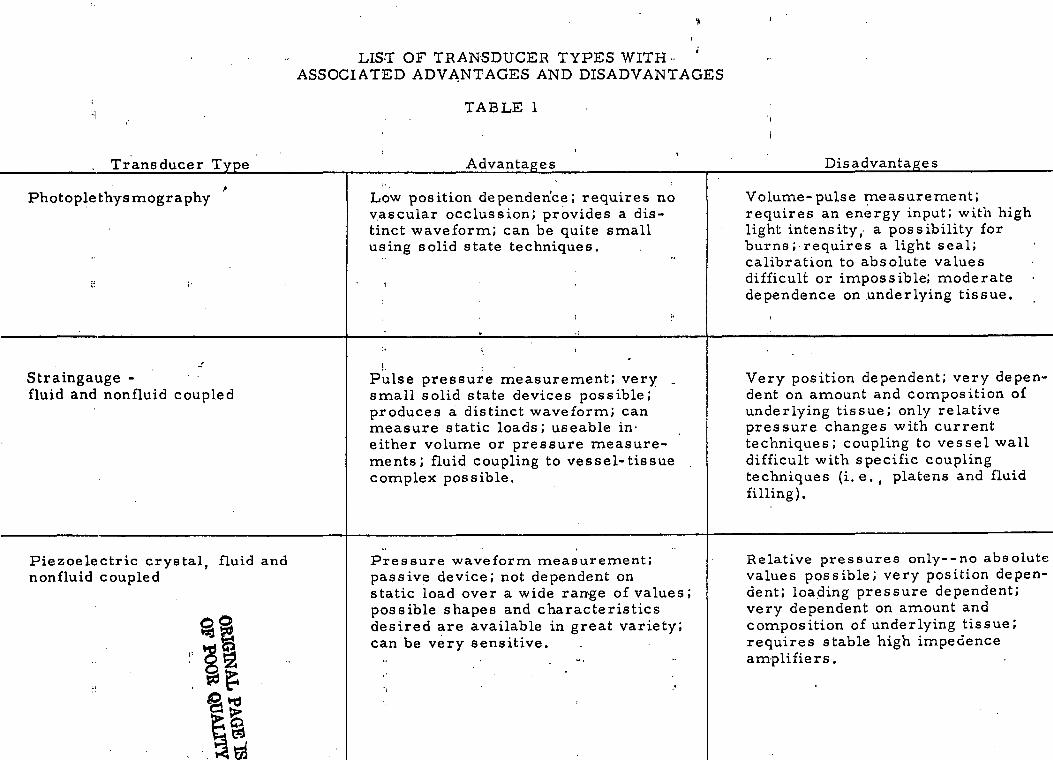
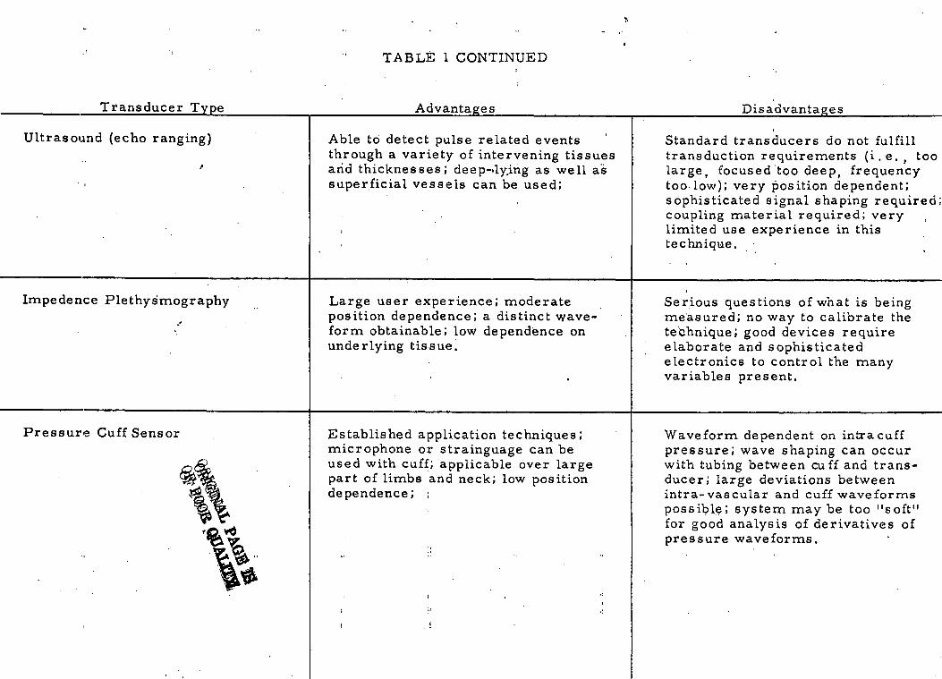
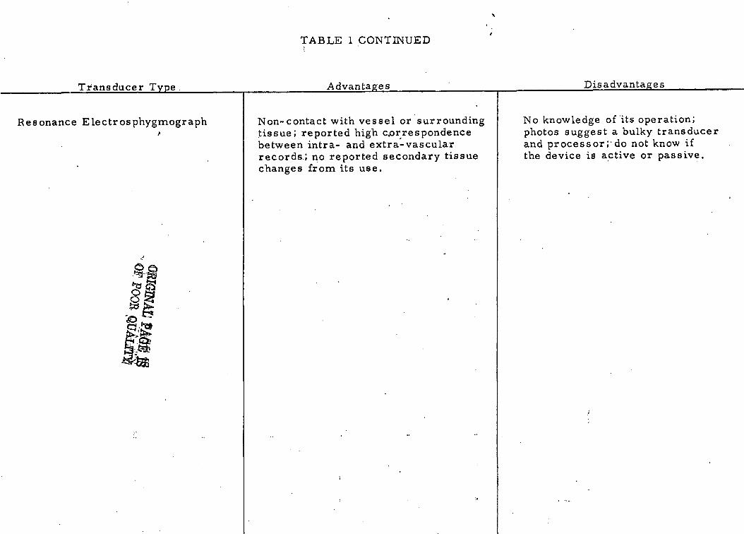
A-s.ummary--.of the devices considered .worth further investigation is shown->-
in Table I. For each of the devices a brief list of advantages and dis-
advantages is provided.
Sites o f Transduction • • - . . > . . ; . . . i . • i
The brachial artery has been the more common site to determine blood
pressure. This preference for the brachial artery may stem largely from
its closeness to the surface and ease of placing cuffs around the limb.
"However,* othe*- -sites are--available where -arteries are palpable.: Beyond the •-'
availability of the pulse, the amount of diagnostic information within the
pulse becomes important. It has been asserted that the brachial and radial
artery pulses contain less information about central pressure events than
the-carotid artery. No comparison between the temporal artery and
aortic pressures was readily found in the literature. However, the temporal
artery is an attractive site for measurements since it is close to central
arteries and has little overlying tissue to make coupling to a transducer
difficult.-"HoweveT-^-it-'is *a= small•-• a-rtery-and may present waveforms-"•-'—* •"«•-«
consistent with its size.
Other sites deserving consideration include the carotid artery, brachial\.,
and radial-arteries, and the femoral artery. The carotid-artery'and- :T-'~^~-
perhaps the temporal artery provide a good source of pulse pressure wave-
forms that are closely correlated with central pulse pressures. The
-13-
W-
o
ffiW
CO
OF TRANSDUCE' ADVANTAGES j
Og wuo
TABLE 1
Disadvantages
,
toQ)bl
rt"Srt
TD(UOK^
?•
H0uT3toCrtj-,H
._r!bO
Volume-pulse measurement;requires an energy input; with hilight intensity ,- a possibility forburns ; requires a light seal;calibration to absolute valuesdifficult or impossible; moderatedependence on underlying tissue.
oa ito
.C
O -rt
^(D
"T3
««*
ro
•S rt
g
«f " v
•
_ rO
f %
0}
T-l
«T-I
Q)
0 o cr ^H
S ^^ J
'U
"en r« O
X
C
C
Q.
CX. to (,)
tu to • " 4->
"O ,2
S
j*
'C
"o £ o>
0
U «
2 T
J4J
0 -rt
• r4
^ .—
4ro
tjj rt
°5
r—
1
jj
™
3
gj)
^
0
rt
C 'S
:
-
J
>'JJ 3
V
o.rtUDOC03>N
^
: :u
ao"o0,
ic<y ,^4
O-
rt ""^
^
Very position dependent; very dedent on amount and composition <underlying tissue; only relativepressure changes with currenttechniques; coupling to vessel wadifficult with specific couplingtechniques ( i .e . , platens and flu;filling).
*>» ; . .
y m
JH m
C
Jj
030) r-4 rt 1. "
Tj
' > a « -S S Iii
«> ',: CD Q> 0C
jo S
7; g
to0)
r N
-5 oo
C
<+H
0 r]
^0)
™
CU
CO
3
" >
^ to Q
J G
O™
Q
) -0
I* G
. « no
0 rt a^| .
0
**
'•" O
^
n.. .^
rt (Q
O
O
^
03
^
rt
g rrj tD
»t T3
•-*•*-* n
X
O00
:L
rt ii\
D
V^!
«^ -rt
u
« ^
.3
(X.
CX, to
">
2J
** *"
^u
3 " ~ ,5J
0
• • 3
m
Jj Q
Jm rt
^
rt
* C
d^
C °
0
•£
S S
-•• - :.P
c ^ S •" S °PH
CD
CL C 0>
C O
T300UTJ
'3VHC0
O00 C
3rt -gW
) ^
c"^^ *o
2 '3
cod
0) 1
•" G
r2
^^
C
L..
Relative pressures only--no abs<values possible; very position dedent; loading pressure dependentvery dependent on amount andcomposition of underlying tissue;requires stable high impedenceamplifiers.
01
r3
W
0
^
rt o
-r^J-3
j^ —
»0)
£ *+-» W
>
Su O
<
rH
J_>
?-t
4-J
j (U
9^ fj ~^
- to
Q
rt ™
M
rt "^
^ rt
Cg
O<
(J) ^
3
-r-l<D
m
T
»
*^ "0 0
0 0
g « ? -g
3 .^
8S
-S5
**tt
•« h
oo rt
C""
0
0
0
>
0
,^
cj >
CX
rt to.
S > ° 2 0 >,0
T3
m
Vi JH
<U T
3
rt rt
0
rt
0
r-H
rrt 'V
5
>
J3 0
0M
S 'rt
U
••-*
^|
rt^
10 V
^ 03
.rt
^ to
,3 en co
C1 ^*
rt 4-> O
0
rt -
- •"
fii a
to a, ro
o
crtT3
_Q3
/vB'tf fTMALi PA
GE
*^*.
OF
POO
E O
PA
Ifl*rt
•-!.j ^
ID^*
o ^So ^
"" i S*jl
Oo uJS
-o •
: •••••<u
-^o J2N
C0
G
SI c
QWD2OUwJPQ<qH
DisadvantagesCOCOcun)4->aci>T3
<coa>•HM0)o3T3COnSf-i
H
O
T3
0
a)
-
Standard transducers do not fulfi l ltransduction requirements ( i . e . , tlarge, focused too deep, frequencytoo low); very position dependent;sophisticated signal shaping requircoupling material required; verylimited use experience in thistechnique.
COCO
;COd rtCO
.m
C
O ^
->-> £ <o
C
5 ..
«\ >**\ *^
(U
OO
rjj
>
C
CO
Q)
<" '2
rt
CO
T3
CO
50 •*
0) >
-C
0
, -
•"
»H
••"'.
0rt £
^^
"« £ 1
" c
h .5
C
L g
«*s SCO
°
r£ W
. ™
r—
t
*3 >».. <u^"S
«»
S
»s:s'cu
™ <»
4J
>
CO
r-l
<u C
rtTJ
™ •;*
.n
rj U
.^°
M
I'S J«
d^-£ »*•to
o a>
7^ h 13
a<%
Jc
'C
3 •
- -
<i -i_>
rt co
'oo «.
C• r^CiOCrt)Ho^C0CO
'UCr^
- —
6COn)Vi^_iP
1
Serious questions of what is beingmeasured; no way to calibrate thetechnique; good devices requireelaborate and sophisticatedelectronics to control the manyvariables present.
cu> g
U
«»
°U
/ _^
-" ^
CO
a jj O
h o
C<i>
5 oj
-o .S-o
\J 4->
rf
S 2 «c ^
ex
•- co
CO
rtT,
S » ^
• 2 0
°
i ii
"^ •
'
h
C .. C
OCO
CO
" ? d
CLi'a ®
-
^^ ,.-ii C
O* g 3
S •CO
C
O
M
T->
^ °- c •"
S -S -3 s°«
-2 Sd
C 43
>,0
0^
CO
-r-l L
.
S3-- fi S
2
CO
t, T
J*
0
o
CM
a»A
d
>^r!r±
*CL
n)M? -
g'CO>N
^c1 *
0>^—
1d<COUcT
JCOaccI-H
Waveform dependent on intracuffpressure; wave shaping can occurwith tubing between cuff and trans-ducer; large deviations betweenintra- vascular and cuff waveformspossible; system may be too "soft"for good analysis of derivatives ofpressure waveforms.
l
.COM
g
M
f
O
* «
^ '"
CO n
(o -t->•3 •"
1-1
T<
7-T*
C
~* C
O
•^ rt h 0
c S ° o-
p ° >o ^
O
CO
u
?CO
W)
nj O
•" rd
,55 -•
C
d rQ
-.
o W
) n) J«i• r-l
C
0
U4J
-r-l -1
-1
fl),r*
n* •—
t ;r
r , ,
O. C
U
*•" n
• rl J->
C
lirQr—
* rn
M
^1
o, ro a
c«x n 4;. m
- .--.:
_ .-,. -.rt 0 ««
m
'Q a> o -S
«S
S
r-
B 0
,JS
O
.rt
r;
2 -S •- ^ «£
0- &
*« T
3x> 2
°
cnj
w ro
jj
flj•*-» "
to h a
W
S
03 rt
OJ
;
- -
H
C
d
CL
T3
c^^^_ji^
3^
*C
\^^^^^^^^^oS
^^^^
Qr*
^\cvfC'~fj£!vO
^ *•;
>g\a?*C
grt»-iOCOcCO
COx-(**-!_{3
04>Ii•jCOCOCOM&
(4<DOQ
)
COcuCrt>TDrtCO•i-iP
> «
5 *
o rt
G
a.
O
OC
a,
°Z
e ofst a.
ill2
co V
,
£5
_
O T
35
^0
^g a. rt £ (1)
bOC••- 4 co
"2 *C
C
0)dCOCO
rt
QWOu9rt>no
H-
0 Ssi
b. C
w
n'
•-" Q
0) o
COco ,£
(U bO
C
*0 •-
u a>1
3G
coO
C
O
rtvco
TJ
(U0)
CO
^
c *•o S o »<u
, 5T" 4
S 2 h 6
o i o
o
^
C C
HCU
-r-l
*«H
^ C
tb to
•- C
O T3
CO
0) »-i
bD>
O
C
u u rt
CO CO
^CX
I M
U
3Jn0)U3T3COhH
ca-rtMboOfibOexCOOoCO
WCOocrtCoo>CO
more distal the artery, the less it can be related to central pressures,
but the more it can provide information on the pressures and flow into the
limb being examined.
Important too is what diagnostic information the measurement is being
used to detect. One does not examine for peripheral vascular disease in the.
carotid artery. However, while central pressures may give little information
on-atherosclerotic disease, the-blood^flow into the pinna of the ear may.
These considerations lead to a conclusion that a combinational measurement
at more than one site with more than just pressure measurements may
-provide the needed level of reliability for diagnosis. Supporting such a
"multiple1'riieasure'rnent-idea is the fact-that the cardiovascular "system-is - • - • • • •
attempting to preserve tissue perfusion and regulates this perfusion by
baroreceptors centrally and peripherally as well as tissue-vessel responses
to low oxygen tensions in self-regulating vascular beds. The great questions
"diagrib'stically are: whether tissue-perfusion is adequate an4 whether blood-
pressure is being*controlled within normal ranges.
-17-
BIBLIOGRAPHY
1. Heyman, F. "The Arterial Pulse as Recorded Longitudinally, Radially,and Intra-arterially on the Femoral Artery of Dogs." Acta MedicaScandinavia 170;77-81r 1961.
2. Stead, E. A. "Pressures and Pulses." Circulation 31:381-484'rApril 1965.
3. Remington, J. W. "Contour Changes of the Aortic Pulse During Propa-gation, n'Ajnejuc^n_J^u^jiaj_^^h^sj^logY 1 99:331-334, I960.
4. Meisner, J. E. , and J. W. Remington. "Pulse Contour Changes inCarotid and Foreleg Arterial System, " American Journal of- Physiology202:527-535, 1962.
5. Cachovan, M. , J. Linhart, I. Perovsky. "Morphology of the PulseWave Curve from Various Segments of the Lower Limb in Man, "Angiology 19:381-392, 1968.
6. Pressman,, G. L. , P. M. Newgard. "A Transducer for the ContinpusExternal Measurement of Arterial Blood Pressure." IEEE Trans-actions of Biomedical Electronics 10:73-81. April 1963.
7. Pressman, G. L. , P. M. Newgard. Development of a. Blood PressureTransducer for the Temporal Artery. NASA-CR-293, Sept. 1965.
8. Davis, M. , B. Gilmore, E. Freis. "Improved Transducer for ExternalRecording of Arterial Pulse Waves." IEEE Transactions on Bio-medical Electronics. 10:173- 175. 1963.
9. Freis, E. D. "Transducer Application and Carotid Pulse Contours,"Cardiologia 50:61-64. 1967.
10. Dontas, A. S. "Comparison of Simultaneously Recorded Intra- Arterialand Extra-Arterial Pressure Pulses in Man, " American HeartJournal 59:576-590, I960.
11. Robinson, B. "The Carotid Pulse II: Relation of External Recordingsto Carotid, Aortic, and Brachial Pulses, "British Heart Journal25: 61-6,8, Jan. 1.963.
12. Mohammad, S. F. , N. A. Coulter. "Relationships of Arterial Pressureand Electrical Impedance Associated with the Femoral VascularBed of the Dog," American Journal of Medical Electronics 4:132-1351965. !
-18-
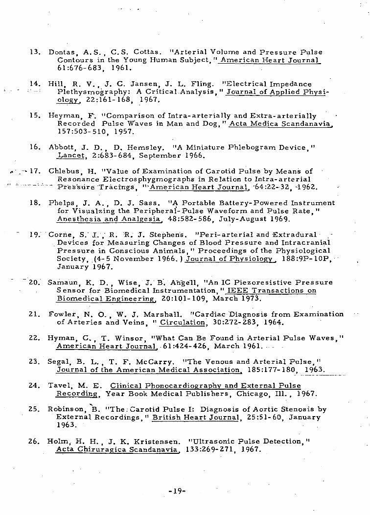
13. Dontas, A.S. , C.S. Cottas. "Arterial Volume and Pressure PulseContours in the Young Human Subject, " American Heart Journal61:676-683, 1961.
14. Hill, R. V. , J. C. Jansen, J. L. Fling. "Electrical Impedance; Plethysmography: A Critical Analysis. " Journal of Applied Physi-
ology. Z2:161-168, 1967.
15. Heyman, F. "Comparison of Intra-arterially and Extra-arteriallyRecorded Pulse Waves in Man and Dog. " Acta Medica ScandanaviaJ
157:503-510, 1957.
16. Abbott, J. D. , D. Hemsley. "A Miniature Phlebogram Device, "Lancet, 2:683-684, September 1966.
. - 17. Chlebus, H. "Value of Examination of Carotid Pulse by Means ofResonance Electrosphygmographs in Relation to Intra-arterialPressure'Tracings, "'American Heart Journal^ '64:2-2- 32, -1962.
18. Phelps, J. A. , D. J. Sass. "A Portable Battery-Powered Instrumentfor Visualzing the Peripheral-Pulse Waveform and Pulse Rate,"Anesthesia and Analgesia. 48:582-586. July-August 1969.
19. Corhe, S. J. , R. R. J. Stephen's. "Peri-arterial and Extradural .-Devices for Measuring Changes of Blood Pressure and IntracranialPressure in Conscious Animals," Proceedings of the PhysiologicalSociety, (4-5 November 1966. ) Journal of Physiology^ 188:9P-10P,January 1967.
20. Samaun, K. D. , Wise, J. B. Angell, "An 1C Piezoresistive PressureSensor for Biomedical Instrumentation. " IEEE Transactions onBiomedical Engineering. 20:101-109, March 1973.
21. Fowler, N. O. , W. J. Marshall. "Cardiac Diagnosis from Examinationof Arteries and Veins, " Circulation. 30:272-283, 1964.
22. Hyman, C, , T. Winsor, "What Can Be Found in Arterial Pulse Waves,"American Heart Journal. - 61:424-426. March 1961. .— -
23. Segal, B. L. , T. F. McCarry. "The Venous and Arterial Pulse, "Journal of the American Medical Association. 185:177-180, 1963.
24. Tavel, M. E. Clinical Phonocardiography and External PulseRecording^ Year Book Medical Publishers, Chicago, 111. , 1967.
*».25. Robinson, B. "The. Carotid Pulse I: Diagnosis of Aortic Stenosis by
External Recordings " British Heart Journal 25:51-60, January1963.
26. Holm, H. H. , J. K. Kristensen. "Ultrasonic Pulse Detection, "Acta Chiruragica Scandanavia. 133:269-271, 1967.
-19-

27. Aleksandro, D. , A. Horst. "Problems of Atherosclerosis in Poland, "Circulation. 20:922, 1959.
28. Goldberg, B. B. Diagnostic Ultrasound in Clinical Medicine, MedcomPress. New York, 1973.
29. Masumi, R. A. , R. Zeis, N. Ali, D. T. Mason. "External Venousand Arterial Pulses,11 from Noninvasive Cardiology, edited byArnold M. Weissler, Grune and Stratton, New York, 1974.
30. Mason, D. T. , E. Braunwald, J. Ross, A. G. Morrow. "Diagnostic"Value of the First and Second Derivatives of the Arterial PressurePulse in Aortic Valve Disease and in Hypertrophic Subaortic Stenosis,"Circulation. 30:90-100, 1964.
-31. Simmons, E. M. , H. Leader, S. A. Friedman, B. Davis, D. Lee,T. Winsor, C. A. Caceres, "A Computer Program for the PeripheralPulse Wave. " American Journal of Cardiologyr 19:827-831, 1967.
32. Kyle, M. C. , J. D. Klingeman,, E. D. Fries. "Computer Identificationof Brachial Arterial Pulse Waves," Computers and BiomedicalResearch. 2:151-159, 1968.
33. Rautaharju, -P. M. "Hybrid and Small Sepcial-Pur pose Computers inElectrocardiographic, Ballistocardiographic and Pulse WaveResearch. " Annals of the New York Academy of Sciences. 126:906-918, August 1965..
34. "How the Ear May Reveal the Heart," Medical World News 15:23,December 20, 1974.
-20-
kPPENDlX A
Review of
u«
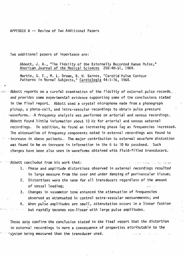
APPENDIX A — Review of Two Additional Papers
Two additional papers of importance are:
Abbott, J. A., "The Fidelity of the Externally Recorded Human Pulse,"American Journal of the Medical Sciences 258:40-51, 1969.
Martin, G. E., M. L. Brown, R. H. Barnes, "Carotid Pulse ContourPatterns in Normal Subjects," Cardiologia 44:1-16, 1964.
Abbott reports on a careful examination of the fidelity of external, pulse-records.,. .and provides some experimental evidence supporting some of the conclusions statedin the final report. Abbott used a crystal microphone made from a phonographpickup, a photo-cell, and intra-vascular recordings to obtain pulse pressure
»waveforms.--A frequency analysis was performed on arterial and venous recordings.Abbott found little information about 10 Hz for arterial and venous external
/recordings. In addition, he found an increasing phase lag as frequencies increased.The attenuation of frequency components noted in external recordings was found to
-increase in obese patients.- The-major contribution to external waveform distortionwas found to be an increase in information in the 6 to 10 Hz passband. Suchchanges have been also seen in waveforms obtained with fluid-filled transducers.
Abbott concluded from his work that: . ...-.?- ,.-.,:. .--..-.1. Phase and amplitude distortions observed in external recordings resulted
in large measure from the over and under damping of perivascular tissue;2. Distortions were the same for all transducers regardless of the amount
o f vessel loading; . - : - . : •3. Changes in vasomotor tone enhanced the attenuation of frequencies
observed as attenuated in control extra-vascular measurements; and•*,
4. When pulse amplitudes are small, attenutation occurs in a linear fashionbut rapidly becomes non-linear with large pulse amplitudes.
These data confirm the conclusion stated in the final report that the distortionin external recordings is more a consequence of properties attributable to the
"system being measured than the transducer used. - •-- -
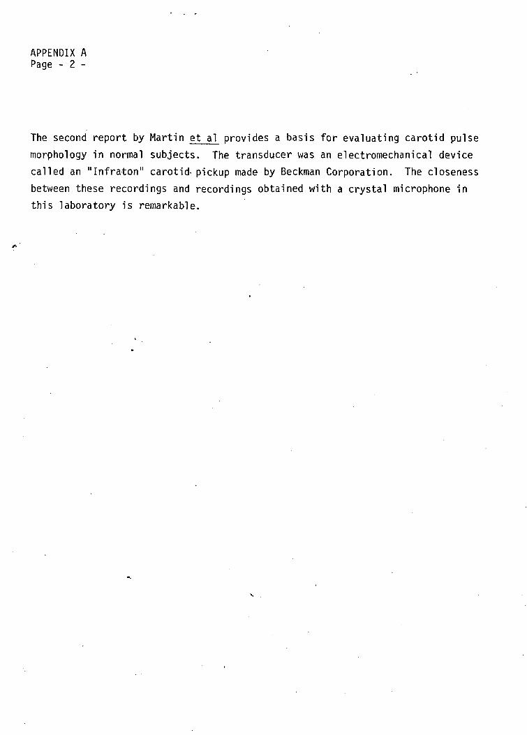
APPENDIX APage - 2 -
The second report by Martin et al^ provides a basis for evaluating carotid pulsemorphology in normal subjects. The transducer was an electromechanical devicecalled an "Infraton" carotid- pickup made by Beckman Corporation. The closenessbetween these recordings and recordings obtained with a crystal microphone inthis laboratory is remarkable.

APPENDIX B
Schematic of Pulse Wave Analysis Breadboard
BLANK NOT
OuJ
H
T K
T1
,OcQoc:to
APPENDIX C
Waveforms from Pulse Wave Analysi:Breadboard
, ,J tif AH*
PACE SUNK NOT FILMED!

Blood PressureUnder High Noise
Environments
ELANS
Blood Pressure Under High Noise Environments
Literature Study
In accordance with the Statement of Work, it is the purpose of the first part of
this effort to search current literature in order to establish what the "state of
the art" is in blood pressure microphones and to recommend future efforts at im-
proving the noise rejection characteristics of a blood pressure microphone.
Specifically, a "best" choice technique for optimum detection of blood pressure
"Korotkoff" sounds in high ambient noise environments must be determined. In
order to assist in determining what a best technique might be, a list of desirable
properties has been established.
1. Maximum signal-plus-noise-to-noise ratio
2. Inherent artifact rejection characteristics
3. Small enough for use with a cuff and thin enough to prevent
pressure amplification under cuff
4. Rugged
5. Lighweight
6. Noise cancelling and directional
7. Inexpensive
8. A constant amplitude sensitivity to dynamic pressures in a
large static pressure field. r -... .
All of the above criteria are based on the premise that the device is compatible
with existing Skylab blood pressure system design.
In addition to the above general overview of the problem, specific topics are
of particular interest including investigation of geo-phone type transducers
and special noise-cancelling type microphones.
Of primary importance are sources of artifact and noise which may mask signals
of interest. Ambient noise, of course, could consist of any frequency, amplitude,
and duty cycle making a generalized definition impossible. Artifact sources,
however, generally consist of erratic sensor-patient motion and external forces
causing vibration of the microphone directly or indirectly. Artifact disturbances
sometimes can be controlled by soliciting user cooperation during critical-' ' y
measurement cylles. However, efforts to design against artifact not be disregarded
since artifacts may be beyond the control of the user such as in environmental
vibration.
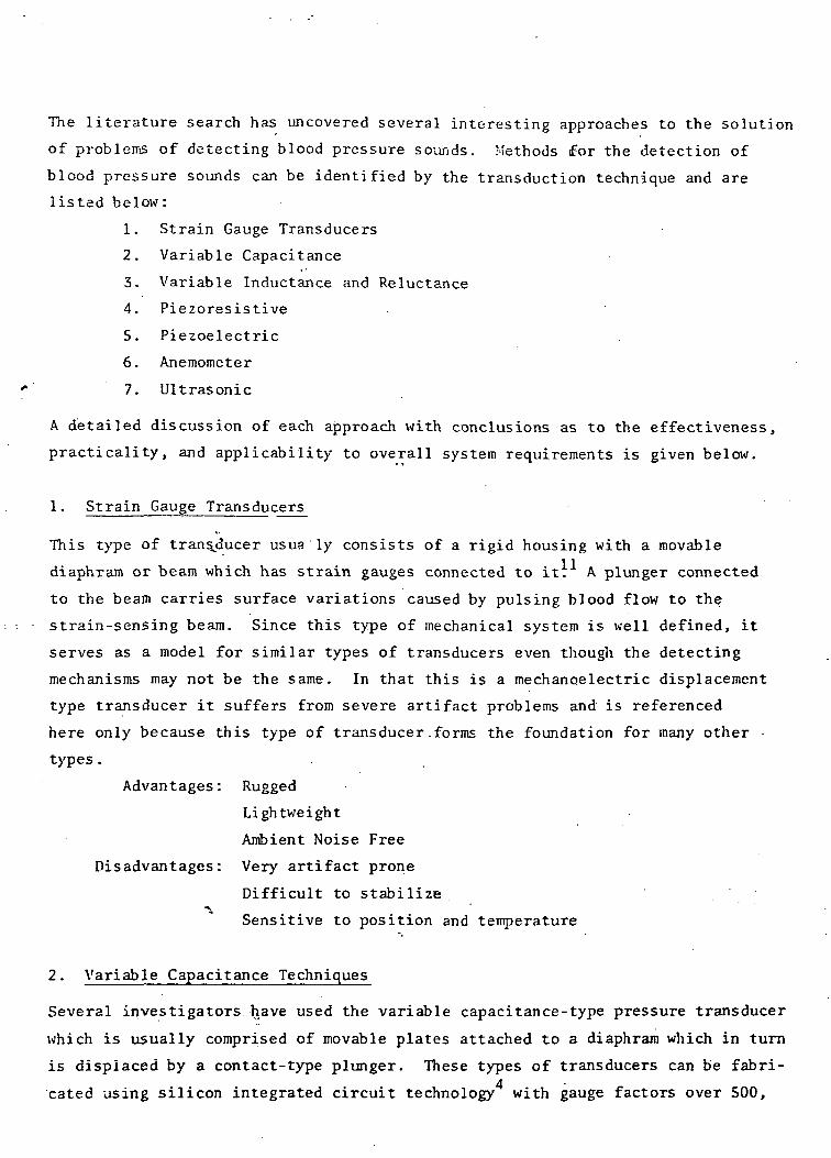
The literature search has uncovered several interesting approaches to the solution
of problems of detecting blood pressure sounds. Methods for the detection of
blood pressure sounds can be identified by the transduction technique and are
listed below:
1. Strain Gauge Transducers
2. Variable Capacitance
3. Variable Inductance and Reluctance
4. Piezoresistive
5. Piezoelectric
6. Anemometer
7. Ultrasonic
A detailed discussion of each approach with conclusions as to the effectiveness,
practicality, and applicability to overall system requirements is given below.
1. Strain Gauge Transducers
This type of transducer usus ly consists of a rigid housing with a movable
diaphram or beam which has strain gauges connected to it. A plunger connected
to the beam carries surface variations caused by pulsing blood flow to the
strain-sensing beam. Since this type of mechanical system is well defined, it
serves as a model for similar types of transducers even though the detecting
mechanisms may not be the same. In that this is a mechano.electric displacement
type transducer it suffers from severe artifact problems and is referenced
here only because this type of transducer-forms the foundation for many other
types.
Advantages: Rugged
Lightweight
Ambient Noise Free
Disadvantages: Very artifact prone
Difficult to stabilize•
Sensitive to position and temperature
2. Variable Capacitance Techniques
Several investigators have used the variable capacitance-type pressure transducer
which is usually comprised of movable plates attached to a diaphram which in turn
is displaced by a contact-type plunger. These types of transducers can be fabri-4cated using silicon integrated circuit technology with gauge factors over 500,
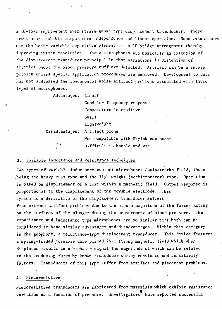
a 10-to-l improvement over strain-gauge type displacement transducers. These
transducers exhibit temperature independence and linear operation. Some researchers
use the basic variable capacitive element in an RF bridge arrangement thereby
improving system resolution. These microphones are basically an extension of
the displacement transducer principal in that variations in distention of
arteries under the blood pressure cuff are detected. Artifact can be a severe
problem unless special application procedures are employed. Development to date
has not addressed the fundamental noise artifact problems associated with these
types of microphones.
Advantages: Linear
Good low frequency response
Temperature insensitive
Small
Lightweight
Disadvantages: Artifact prone
Non-compatible with Skylab equipment
bifficult to handle and use*
3. Variable Inductance and Reluctance Techniques
Two types of variable inductance contact microphones dominate the field, those
being the heavy mass type and the lightweight (accelerometer) type. Operation
is based on displacement of a core within a magnetic field. Output response is
proportional to the displacement of the movable electrode. This
system as a derivative of the displacement transducer suffers
from extreme artifact problems due to the minute magnitude of the forces acting
on the surfaces of the plunger during the measurement of blood pressure. The
capacitance and inductance type microphones are so similar that both can be
considered to have similar advantages and disadvantages. Within this category
is the geophone, a reluctance-type displacement transducer. This device features
a spring-loaded moveable core placed in c. strong magnetic field which when
displaced results in a biphasic signal the magnitude of which can be related
to the producing force by known transducer spring constants and sensitivity
factors. Transducers of this type suffer from artifact and placement problems.
4. Piezoresistive
Piezoresistive transducers are fabricated from materials which exhibit resistance9
variation as a function of pressure. Investigators 'have reported successful
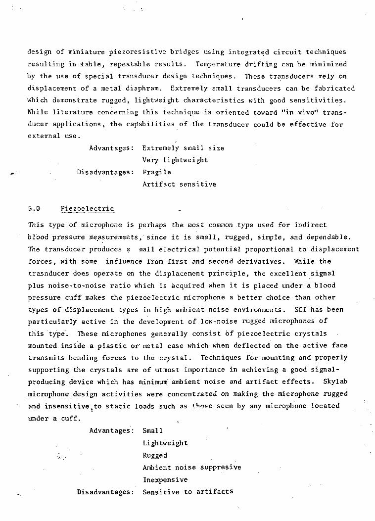
design of miniature piezoresistive bridges using integrated circuit techniques
resulting in ±able, repeatable results. Temperature drifting can be minimized
by the use of special transducer design techniques. These transducers rely on
displacement of a metal diaphram. Extremely small transducers can be fabricated
which demonstrate rugged, lightweight characteristics with good sensitivities.
While literature concerning this technique is oriented toward "in vivo" trans-
ducer applications, the capabilities of the transducer could be effective for
external use.
Advantages: Extremely small size
Very lightweight
Disadvantages: Fragile
Artifact sensitive
5.0 Piezoelectric
This type of microphone is perhaps the most common .type used for indirect
blood pressure measurements, since it is small, rugged, simple, and dependable.
The transducer produces a mall electrical potential proportional to displacement
forces, with some influence from first and second derivatives. While the
trasnducer does operate on the displacement principle, the excellent signal
plus noise-to-noise ratio which is acquired when it is placed under a blood
pressure cuff makes the piezoelectric microphone a better choice than other
types of displacement types in high ambient noise environments. SCI has been
particularly active in the development of low-noise rugged microphones of
this type. These microphones generally consist of piezoelectric crystals
mounted inside a plastic or metal case which when deflected on the active face
transmits bending forces to the crystal. Techniques for mounting and properly
supporting the crystals are of utmost importance in achieving a good signal-
producing device which has minimum ambient noise and artifact effects. Skylab
microphone design activities were concentrated on making the microphone rugged
and insensitive^to static loads such as those seen by any microphone located
under a cuff.
Advantages: Small
Lightweight
• ' • > . . • Rugged
Ambient noise suppresive
Inexpensive
Disadvantages: Sensitive to artifacts
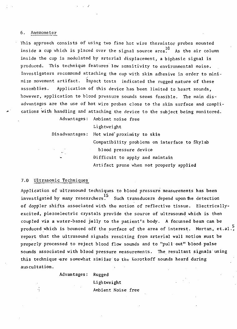
6. Anemometer
This approach consists of using two fine hot wire thermistor probes mounted
inside a cup which is placed over the signal source area. As the air column
inside the cup is modulated by arterial displacement, a biphasic signal is
produced. This technique features low sensitivity to environmental noise.
Investigators recommend attaching the cup with skin adhesive in order to mini-
mize movement artifact. Impact tests indicated the rugged nature of these
assemblies. Application of this device has been limited to heart sounds,
however, application to blood pressure sounds seems feasible. The main dis-
advantages are the use of hot wire probes close to the skin surface and compli-
cations with handling and attaching the device to the subject being monitored.
Advantages: Ambient noise free
Lightweight
Disadvantages: Hot wire" proximity to skin
Compatibility problems on interface to Skylab
- • • • blood pressure device
Difficult to apply and maintain
Artifact prone when not properly applied
7.0 Ultrasonic Techniques
Application of ultrasound techniques to blood pressure measurements has been
investigated by many researchers. Such transducers depend upon the detection
of doppler shifts associated with the motion of reflective tissue. Electrically-
excited, piezoelectric crystals provide the source of ultrasound which is then
coupled via a water-based jelly to the patient's body. A focussed beam can be
produced which is bounced off the surface of the area of interest. Mortan, et.al. ,
report that the ultrasound signals resulting from arterial wall motion must be
properly processed to reject blood flow sounds and to "pull out" blood pulse
sounds associated with blood pressure measurements. The resultant signals using
this technique -are somewhat similar to the Korotkoff sounds heard during
auscultation. -
Advantages: Rugged
Lightweight
; Ambient Noise free
Disadvantages: Coupling jelly must be used
Artifact noise susceptable
Expensive
Additional circuitry required to interface to
Skylab Blood Pressure Device
Conclusions
Based on this literature search, "state-of-the-art" blood pressure microphone
appear not to have changed radically, nor is there evidence of new types that
solve old problems. The most promising improvements so far appear in reports
made by Geddes and Moore whereby placement of piezoelectric crystals inside
the blood pressure cuff instead of below the distal end or inside a pocket
under the inflatable bladder improves signal amplitude resulting in an overall
improvement of signal-to-noise ratio. -Intrinsic noise may or may not be an
important factor in this respect. If the signal + noise-to-noise ratio is high,
then processing the signal for accurate determination of systolic and diastolic
blood pressure can be accomplished. This implies that intrinsic noise levels
are not extremely important as long as their ratio-to-signal is low.
The problem of developing a microphone system which demonstrates improved rejection
of artifact and ambient noise is best approached by considering (1) multiple
crystal systems which may display common mode signal rejecting characteristics,
(2) microphones within the bladder of the blood pressure cuff to determine the
effects of such placement and improvements, if any, on the rejection of ambient
noise and artifact, (3) improved packaging of our existing single crystal type,
such as lead encasement on the back side with increased mass and possible reduction
of artifact effects, and (4) modifications to the cuff assembly for improvement
of the system. Directivity and its relationship to position sensitivity will be
studied. Compafison analysis to the Littman Stethoscope and why this technique
is so effective will be made in an effort to develop a microphone with much«.
improved artifact and ambient noise rejection effects.
1. K . S . Lion, Instrumentation in Scientific Research. New York:McGraw-Hill , 1959.
2. L.Cromwell , F.J. Weibell, E .A. Pfeiffer, L . B . Usselman, Biomedical Instru-mentation and Measurements. New Jersey:Prentice-Hall, Inc., 1973.
3. Peter Strong, Biophysical Measurements. Oregon:Tketronix, Inc., 1971.
4. W . D . Frobenius, A.C. Sanderson, H . C . Nathanson, "A Microminiature Solid-StateCapacitive Blood Pressure Transducer with Improved Sensitivity," IEEETransactions on Biomedical Engineering, pp. 312-314, July 1973.
5. A . R . Soffel, "A New Low-Noise Condenser Microphone," Journal of the AudioEngineering Society, vol. 14, pp. 240-243, July 1966.
6. E. Van Vollenhoven, "Calibration of Contact Microphones Applied to the HumanChest Wall," Medical 5 Biological Engineering, vol. 9, pp. 365-373, 1971.
7. K.Ikegaya, N. Suzumura, and T. Fun'ada, "Absolute Calibration of Phonocardio-graphic Microphones and Measurements of Chest Wall Vibration," Medical and_Biological Engineering, vol. 9, pp. 683-692, 1971.
8. Harry F. Olson, "Calibration of Microphones by the Principles of Similarityand Reciprocity," Journal of the Audio Engineering Society, vol. 17, number 6,pp. 654-656, December 1969.
9. Samaun, Kensall D. Wise, and James B. Angell, "An 1C Piezoresistive PressureSensor for Biomedical Instrumentation," IEEE Transactions on BiomedicalEngineering, vol. BME-20, no. 2, pp-101-109, March 1973.
10. D . E . Laughlin and R .P . Mahoney, "New Phonocardiographic Transducers Uti l izingthe Hot-Wire Anemometer Principle," Medical., and Biological Engineering, vol. ;0,pp. 43-55, 1972.
11. G .L . Pressman .and P.M. Newgard, "A Transducer for the Continuous ExternalMeasurement of Arterial Blood Pressure, IEEE Transactions on Bio-MedicalElectronics, pp. 73-81, April 1963.
12. Amiram Ur and Michael Gordon, "Origin of Korotkoff Sounds," American Journalof Physiology, vol. 218, no. 2, pp. 524-529, February 1970.
13. L.A. Geddes and A.G. Moore, "The Efficient Detection of Korotkoff Sounds,"Medical § Biological Engineering, voi: 6, pp. 603-609, 1968.
14. John M. Lagerwerff and Robert S. Luce, "Artifact Suppression in Indirect BloodPressure Measurements," Aerospace Medicine, pp. 1157-1161, October 1970.
15. J.L. Morgan, "Doppler Shifted Ultrasound," Advance, pp. 503-506, March 1969.
Experimental Results
Experiments were undertaken to investigate the possibility of improving the
performance of microphones presently used in blood pressure measurement
instruments. Our efforts were broken into three categories: (1) investi-
gation of other sensor types, (2) hypothetical improvement of existing
sensors, and (3) experimental evaluation. Testing was performed on a dummy
arm which simulated an arterial pulse wave. Artifacts were simulated in a
repeatable manner to evaluate the artifact rejection performance of each
sample. Each microphone was also'evaluated during actual blood pressure
measurements using a standard blood pressure measuring system.
The microphone found most successful at this time is manufactured by^Telecare
for several commercial applications. Simple in concept, it is fundamentally a
piezoelectric crystal bonded to a thin- sheet of brass for strengthening.
This crystal assembly is potted in a protective case using soft silicone
rubber. The crystal is edge-supported in such a manner that forces on the
surface of the potting product flexure charges on the crystal. A trans-
conductance amplifier converts these dynamic charge currents to a voltage
signal. In practice, there is no clear distinction between the response of
the crystal when loaded with a force and the response when subjected to
acceleration normal to the surface of the crystal. Although the physical
phenomena of these stimuli are greatly different, flexure charges are
generated in either case. Since pressure loading and unloading is always
present during a useful measurement cycle, it appears desirable to. investigate
any sensor type which would respond to acceleration only. Several geophones
were acquired in order to assess their performance. These transducers were
found to be extremely sensitive to forces tangential to the axis of orientation
and required extreme overdamping such that they could not be considered useful
in this application. The geophones having a frequency response low enough to
pick up Korotkoff sound frequencies necessary for determining systolic pressure
could only be used when positioned parallel to the earth's gravity axis due to
the low spring constant of the core support springs in the device. Also, due
to the bulky size of commercially available geophones, application of these
devices to this study was abandoned.
Earlier, the response of the crystal microphone had been described as flexure
response caused either by force loading or acceleration. Artifacts, then,
must be classifiable as either force or acceleration, or both. Considering,
the physical placement of the microphone under the distal edge of the cuff,
it appears that force loading, but not acceleration, could be caused by any
added force on the exterior of the inflated cuff. We have referred to this
force loading as a "cuff bump." Similarly, lateral translation, but not
force loading, could be caused by movement of the arm other than muscle
flexing. We have called this translation effect an "elbow bump."
The small physical size of the crystals normally used in these microphones
suggested the possibility th&t additional crystals might be incorporated into
the microphone housing and arranged in a manner such as to aid artifact
rejection. Two arrangements, shown in Figures^lb and Ic, appeared possible.
Microphone "A" was built with two crystals mounted back-to-back with material
separating the two brass discs only at the edges. The crystals were electri-
cally connected in parallel. This unit would appear to reduce the effect of
acceleration as acceleration would deform the crystals equal amounts in
opposite directions. Charges produced from each crystal in opposite phase
would thus cancel. However, the sensitivity of the top crystal to localized
forces, such as arterial pulses, should be essentially unchanged. (Neglecting
the increased capacitance.)
Microphone "B" was built with two crystals mounted back-to-back, but the
crystals were electrically connected in reverse phase; i.e., the opposite of .
Microphone "A", the concept being that incremental pressure loading deforms
the crystals in the same direction with the reverse-phase wiring allowing
the charges to cancel. Similarly, the presence of localized forces, such as
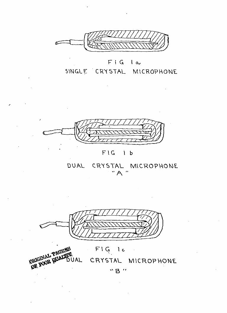
F I G l a ,
SINGLE CRYSTAL MICROPHONE
F I G
CRYSTAL MICROPHONE
F\ G U
CRYSTAL
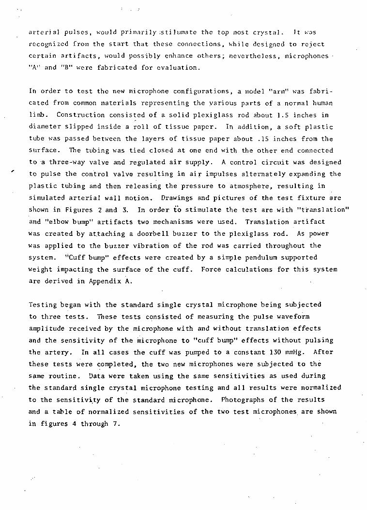
arterial pulses, would primarily ;sti lumate the top most crystal. It was
recognized from the start that these connections, while designed to reject
certain artifacts, would possibly enhance others; nevertheless, microphones
"A" and "B" were fabricated for evaluation.
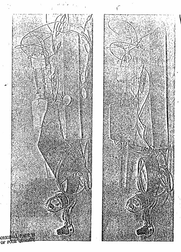
In order to test the new microphone configurations, a model "arm" was fabri-
cated from common materials representing the various parts of a normal human
limb. Construction consisted of a solid plexiglass rod about 1.5 inches in
diameter slipped inside a roll of tissue paper. In addition, a soft plastic
tube was passed between the layers of tissue paper about .15 inches from the
surface. The tubing was tied closed at one end with the other end connected
to a three-way valve and regulated air supply. A control circuit was designed
to pulse the control valve resulting in air impulses alternately expanding the
plastic tubing and then releasing the pressure to atmosphere, resulting in
simulated arterial wall motion. Drawings and pictures of the test fixture are
shown in Figures 2 and 3. In order to stimulate the test are with "translation"
and "elbow bump" artifacts two mechanisms were used. Translation artifact
was created by attaching a doorbell buzzer to the plexiglass rod. As power
was applied to the buzzer vibration of the rod was carried throughout the
system. "Cuff bump" effects were created by a simple pendulum supported
weight impacting the surface of the cuff. Force calculations for this system
are derived in Appendix A.
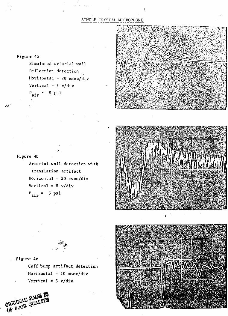
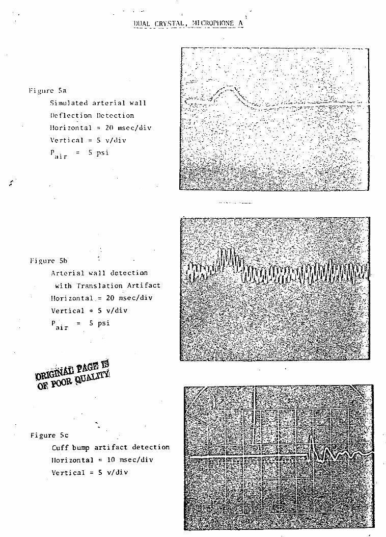
Testing began with the standard single crystal microphone being subjected
to three tests. These tests consisted of measuring the pulse waveform
amplitude received by the microphone with and without translation effects
and the sensitivity of the microphone to "cuff bump" effects without pulsing
the artery. In all cases the cuff was pumped to a constant 130 mmHg. After
these tests were completed, the two new microphones were subjected to the
same routine. Data were taken using the same sensitivities as used during
the standard single crystal microphone testing and all results were normalized
to the sensitivity of the standard microphone. Photographs of the results
and a table of normalized sensitivities of the two test microphones are shown
in figures 4 through 7.
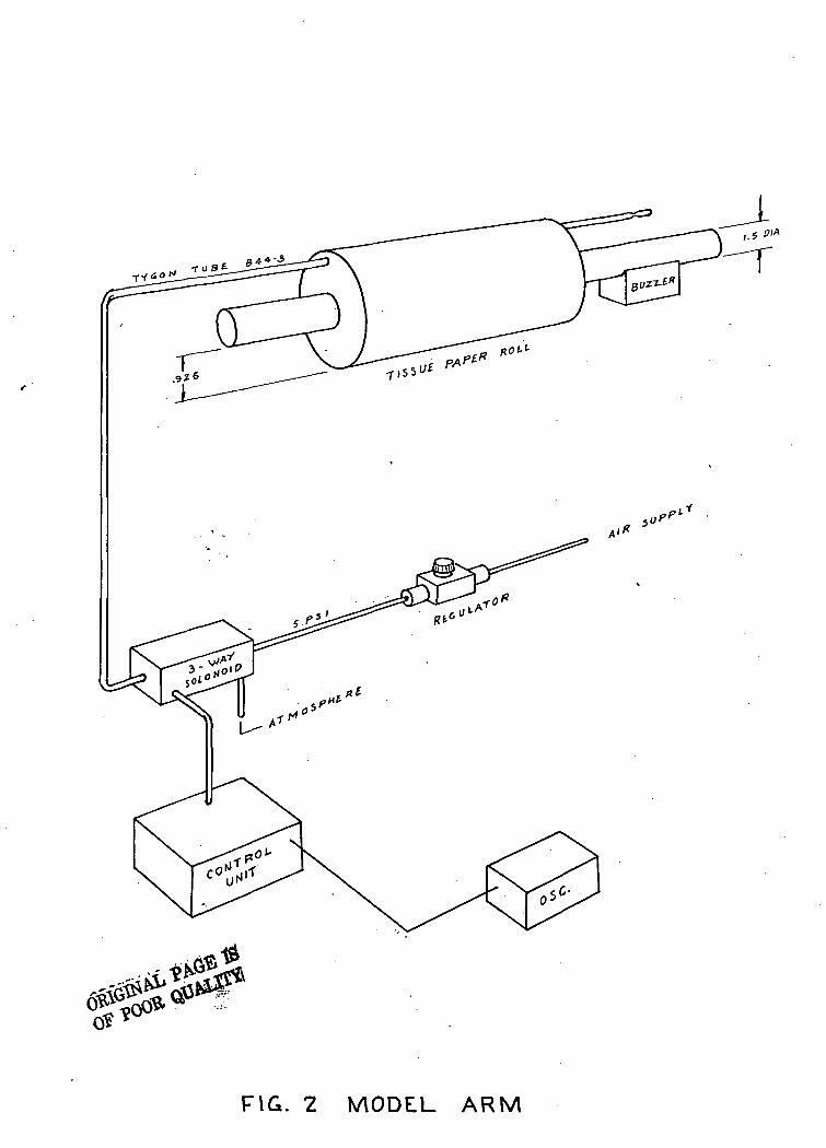
FIG. 2 MODEL ARM
^
/ -*3.asr»iS>/"<t!.- lKrT«'S1.?-« '/'•fs'-'e-.f^.'
SINGLE CRYSTAL MICROPHONE
Figure 4a
Simulated arterial wall
Deflection detection
Horizontal = 20 msec/div
Vertical = 5 v/div
P . = 5 psiair r
Figure 4b
Arterial wall detection with
translation artifact
Horizontal = 20 msec/div
Vertical = 5 v/div
P . = 5 psiair v
Figure 4c
Cuff bump artifact detection
Horizontal = 10 msec/div
Vertical = 5 v/div
DUAL CRYSTAL, MICROPHONE A
:igurc 5a
Simulated arterial wall
Deflection Detection
Horizontal = 20 msec/div
Vertical = 5 v/div
air 5 psi
Figure 5b
Arterial wall detection
with Translation Artifact
Horizontal.= 20 msec/div
Vertical = 5 v/div
air= 5 psi
Figure 5c
Cuff bump artifact detection
Horizontal = 10 msec/div
Vertical = 5 v/div
^ W ^ Sr -'im£ £fe'3&2;g&&
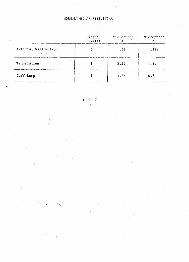
NORMALIZED SENSITIVITIES
Single Mi crophoneA
MicrophoneB
Arterial Wal l Motion
Translation
Cuff Bump
1
1
1
.35
2.57
1.26
.425
1.41
10.8
FIGURE 7
In addition to the previous tests each of the three microphones were used on
a standard SCI blood pressure measuring system in order to determine their
overall sensitivity to Korotkoff sounds during actual measurement cycles. A
subjective evaluation of the rejection of normal artifacts associated with
taking blood pressure was also made. Strip chart recordings were made on each
of the three microphones evaluating unfiltered Korotkoff sound sensitivity
as well as sensitivity to sounds in the frequency bands of interest for
optimum detection of systolic and diastolic blood pressure. It is, of course,
imperative that any transducer used be capable of responding to these frequencies
for accurate detection of these events. These recordings are shown in
Figures 8 through 10.
SCHIIUR BECKMAN INS1BUMFNIS INC.. o'-.i oim
TtTFRTrTPARK, ItL KI*TIO t>« OVA.
! I" i 1
_, rj~±fT •"4 , 11JIi I < ! ] J ,i vJ.-a&rJi
17D3X1 jTT J7 i i-l I TTTiJTTL1JJ1?•:.! I •'
BECKMAN 'INSTRUMENTS INC, «f«t DWS.O-. SCHILLER PARK, 111. name «
=. a*HJF:a^F fc- c;
BECKMAN INSTRUMENTS INC, omn tuvixx. SCHIllER PARK. IU. mKiio M
FIG. 8 STANDARD SINGLECRYSTAL MIC.
EfCKV.A.N INSIRUMSNIS !NC..o..«i.
J_LUJ_ LL J jM 1= I r i i i
-i-t:i n:\W-\:l" 1- ftp i-.E'-Ai J ---J , 1 . 1 _ i_i_J_i_j -frilf<--—* 1 L__ 1 L J
~f i T i iLL-i-U-o-J ' ! Jl J LJ_L i I
•tttttttb
WCKMAN, INSTRUMENTS INC. omci KYU.OH. SCHILLER PACK, ILL RWUD «
LZ--TsJSg;g---f -4 cAifrf:? -ifjiffj-
MOM. SCHIILEB PARK. HI. rc«n> M u.u. BECKMAN INSTRUMENTS INC, on«n moxn. SCHILLER PARK. ILL n>«» « ux*.
«"
f=S
-tr-
:
Sar
••;«:ir«
••Z::i-i
•--.-
•:::
:::i|
fr:
"3
ij—
=-:;_:::
.H
/
55f
TTT
rr-i
==T
rS
q=_
-I::
:-i
H;H:
SiJ
us
:•:.-
.r.:
fe
•:•:
: :i
:;'::::l
min?fit
-T1
rs:
-=:
•Hi.".
•:=i•:!
JfoIEifis.rut
ni£53
"T
52
=3
1*
:::•l*i;::
%&
cii
bd
=3-T"
3s:sj-
'"'p
d;r-
:::
iUTti«:
In?Jtn
ati
"rrt
—
si: r.
:r!
jii
Bia£K:
55
"
1
r.t
Lr3_u:
J:
n:
i::
•tH
Vf
I«L
:TT:
S
NFi:iH
-£
•nS
uj:
&
in:
M-iH
=ri:;~
Si
^
1
3=
t;;~i::
£;!•;^:f
Hit
e,t
.-t
;=
r-if$
•Hfe'HH
Hjl
M
-11
•B::«
oa
. | l
€"=
t«>1
rio:
:mS:
:ni
rrff
nn
HHr=;r-H
un
•m
:;;(
•r-:
ss
u:-;tru.-m
":::
IjJ-J
^g
un-
baj:H
J«
:iH
rar>=^iH
::::
li?«
'•ft
1
r.r
r.t:
|::qu:irrt
; :i::.H
::;;
i!
" T
IJTj
!!:i
ri'iH'i
Fsi™f
^i;
:=::
iir*
LIn :
ill:
•'•'-
-•i
^Pli;
:i
V
H:
•1=
.':::
n:t
.::i
Ml-irt
:';-inti l
ili-":lj ^:
:::
Ji:t32
i
;iii!iii
|ii:
••j:
:;;;
1a
Hit:;
!.:
lt-1iHf
d
::'.!
liii
;i"
:;^::::rr":
"I:
JfS
:li:
>SiI "
FIti i
: ii •
i !:
Pi
i:
'::
: ;;
•!;!
HrlfU
fiiil:;
iiU
nnir::
:.:;
:H
rr;
1!H-.1
HI
I3
ri
-::
•Hi
i;r^
H1"1
--
Hf:
*?;
rr^
;••;::::
FIG.
=n
•:•£
Kli
:.e
•V:
H:•if
in*
^H
;=
-,n"
~
b"5:i:;
IH:
CL;
Hi?
b.-::-.
•fn
i£
Hi;
1:4a
n::::
:••-
::--rr
•s;^u
1
15
•31
'"":
.1:1
iHr
rn;
•3
3U
FtS
IH
.-t;::i
.:
:;i
ir.
^
in?HT
:"i
»
°:ii
Tl.t
i:::-~
M
Uif
Hif
'''I
iHiK.I
•M:
VTT:
«^i;
Hr'
liif
iHi;Hr
H
fin:!!
•;i;
&
Ifir
a-.i
Si
"i:
:;,•
j>-ipj
JP
JUI'.r.i.«ai
=!rHr::~
.!u
iii
;il•!!
a!"
t
9 MICROPHONE A
feir
K rr...n.
a;:
i. :
ili:
•i:i
n^
lift!iff
!£•
..I
lir"i:
:::j
r^rHi£
HH1
i-H,
tm:
. .:
.•i
;'.•.:j|ii-:
Hi;
^u55
asrrrr;
I:1:ii1;'r
??m
bn
".'
;l:j
fJH:rrp
Hf
HE
ah
^. .• •:
^:::
•-N
Hii
ni;
:
::.t
r|
•:~Si
3Hi
USHfr
nt
tf--HiJH
TU;
::::
:."::
at
HH
^=:
!,"
»:;:
::r.
F:;:•^r
_—
iiiigi*£
55
J1I
=:
=f?
-~:
•Hi
[H:
IS*IH;
Ht;
i-.h
«:i
:::
;i:*.rtr
:?=H
dir
;Dl
rrn
i: :
=--•
•l-i.'
'.-.-:-.
s
ffl|
mj
;-jjHH"ii
1
liu
-j:t
:-.:
~.*
:^_
N
d3nlit:
IT::h^^TT
in:
>•.'•,
;|j:
::::
~~
s-iin
~ii::.:
:iH
;;Hi'11
;;.::
:H!
^:i
•Id,in
::!:
Oi:
J
i— iprtr
:r:
^n
j:.. • :t
^
!!;i
•;::
.::
::s
::::
:.-;
"^:
-v
=5-
•:~..£
•^£:
tio
"=?
;;;•
Hi;
::•;
HH:.H
-.-;:
•=%
™
•i.-.
-•::
P
^r:3
-^]
ri:::
:»:
^
:..-
••r
^n
*nn
HH
H;:
—H:u=•HI:
1
mi
H•:=:
:-r-
d•n:
^~
7~
HH
up
~?=
na
=,
~-r
:H
nn:--j
^i
**tl
-•
F=
•H:
:/-a
:r:
-J:
:;
gj
:p.:
~ 5
E::
ss
.-=:
:H:
::
:":::=;
=~
iiti
HH
::r
~
.-::
TtH
im
•i
; H
: :::-J.
iii!^rt
IHi
-"
:r.-
—
r.H
HH
::.:
:'•;;
ihi^=
nil
?m
-.-
^H
HT:
-: =::u:.n
:H:•_•:;
.--
-:
:=:
:=
iiiisfe4U
•ini
:::r
iir
"i:
•H:
::
::::
:L::
T
-..H ~
••-.; ~
H^H,
Hi; 5"
-in:
•- ' -
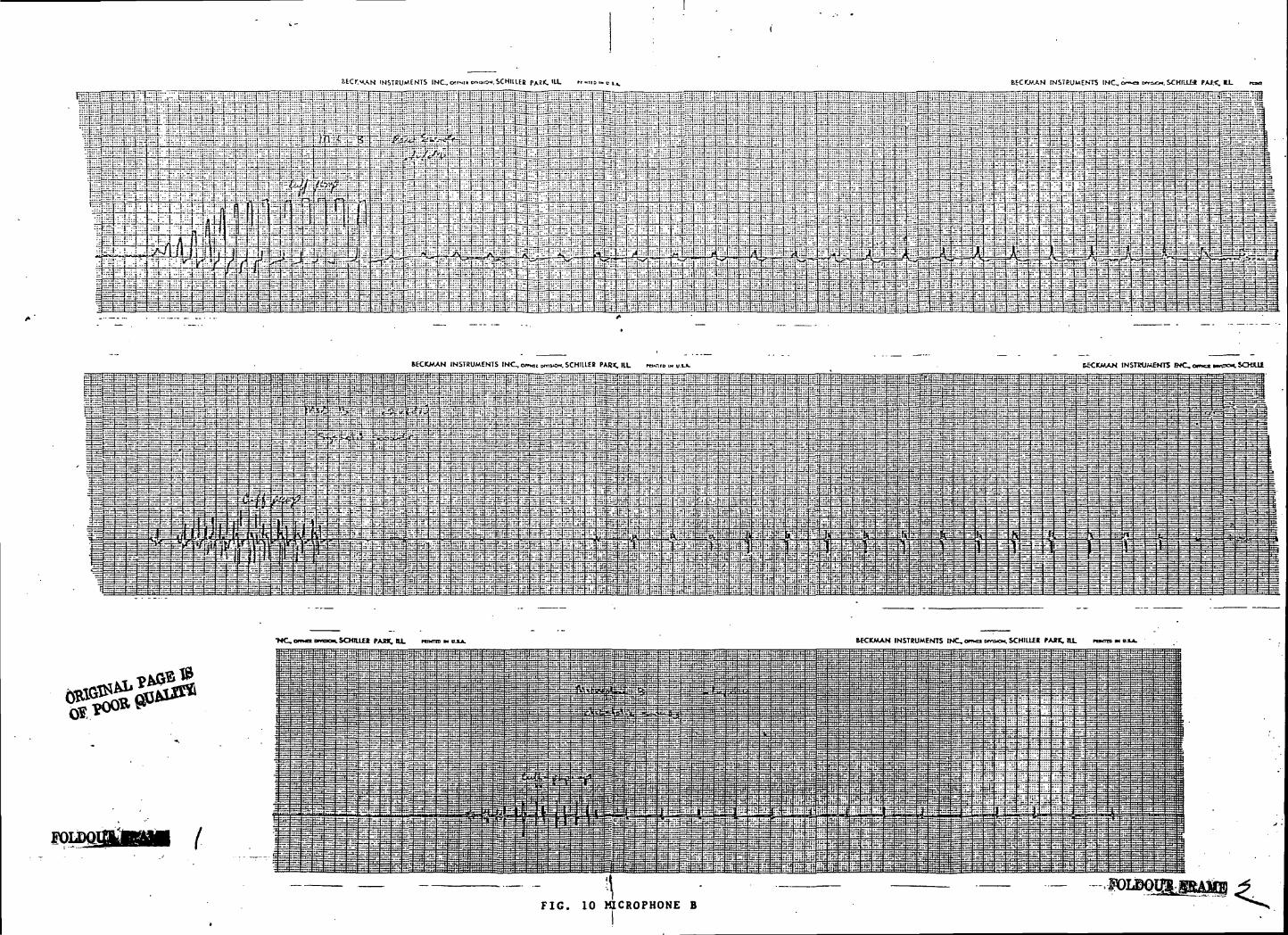
BEC>".MAN INSTRUMENTS INC, cNSTRUMENTS INC.. <xr.«io...»o*.scHtiiEs
MCKMAN INSTRUMENTS INC, omc, HTOKW. SCHIUEt PAR*, lit m«-.r HECKMAN INSTRUMENTS WC,e iSCKUi
- " ^ - • - • - - - - - - -jid^s^ggl l =-'~;1£3±£3''=sS—Ji.- - .- ~&r~f.~4~-ii.r^^nnjr^ j---" — ?rtr "" f""" 1*r'^-^ g~r ;?i.''! ^t^r' i-**-
CfR
•NC,am<XDmKM.SCHIU£R PARK, U. rams m KCKMAN INSTRUMENTS INC, on>o> cmixx. SCHILLER PARK. ILL
FOLD01
FIG. 10 MICROPHONE B
AOl C_
TCP
-7=1
irv\
l^A
2L«-Vt ( '
-WW-!5 - I A A
-».W.'—1
V
^ x
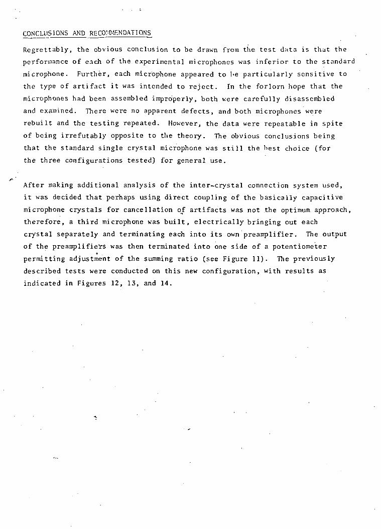
CONCLUSIONS AND RECOMMENDATIONS
Regrettably, the obvious conclusion to be drawn from the test data is that the
performance of each of the experimental microphones was inferior to the standard
microphone. Further, each microphone appeared to l>e particularly sensitive to
the type of artifact it was intended to reject. In the forlorn hope that the
microphones had been assembled improperly, both were carefully disassembled
and examined. There were no apparent defects, and both microphones were
rebuilt and the testing repeated. However, the data were repeatable in spite
of being irrefutably opposite to the theory. The obvious conclusions being
that the standard single crystal microphone was still the best choice (for
the three configurations tested) for general use.
s-'After making additional analysis of the inter-crystal connection system used,
it was decided that perhaps using direct coupling of the basically capacitive
microphone crystals for cancellation of artifacts was not the optimum approach,
therefore, a third microphone was built , electrically bringing out each
crystal separately and terminating each into its own preamplifier. The output
of the preamplifiers was then terminated into one side of a potentiometert
permitting adjustment of the summing ratio (see Figure 11). The previously
described tests were conducted on this new configuration, with results as
indicated in Figures 12, 13, and 14.
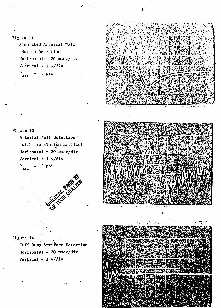
Figure 12
Simulated Arterial Wall
Motion Detection
Horizontal: 20 msec/div
Vertical = 1 v/div
air = 5 psi
Figure 13
Arterial Wall Detection
with translation artifact
Horizontal = 20 msec/div
Vertical = 1 v/div
air .= 5 psi
*&&*££$ *S«2g^p^sgeS*•% •HJiESsaSsSSi
Figure 14
Cuff Bump Artifact Detection
Horizontal = 2t) msec/div
Vertical = 1 v/div
The summing potentiometer was ad jus ted for m i n i m u m re ject ion of s igna l w i t h
maximum rejection of t r ans la t ion a r t i f a c t . R e s u l t i n g l y the signal a m p l i t u d e
in the test configuration was five times less than the standard s ingle crystal
microphone. After scaling all resulting data by a factor of 5 normal ized
sensitivity ratios were calculated as shown below.
Single Crystal Dual Crystal
Arterial Wal l Motion 1 , 1.125
Translation 1 2
Cuff Bump ' 1 .555
As indicated significant reduction of cuff bump was achieved with the new
microphone. Further adjustment of the .summing potentiometer resulted in
further rejection of cuff bump artifact as well as signal amplitude. The
best overall summing ratio for this„microphone was attained when adjustment
for minimum translation artifact was made.
FINAL CONCLUSIONS
Although the final microphone does afford a means for minimization of certain
artifacts signal levels, desired sounds signals are also affected, in addition,
choosing a minimization adjustment for some artifact results in the enhancement
of others as predicted at the outset of this investigation. It is our opinion
that due to the difficulty in making a best choice for summing the two
microphone signals, the Telecare single crystal microphone is still a best choice
for detection of Korotkoss sounds with good rejection of artifact.
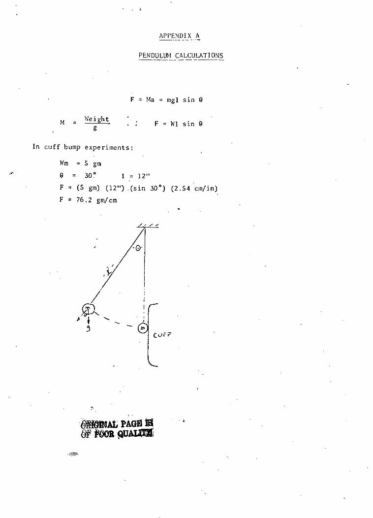
APPENDIX A
PENDULUM CALCULATIONS
M = Weightg
F = Ma = mgl sin 9
F = Wl sin 0
In cuff bump experiments:
Wm = 5 gm
9 = 30° 1 = 12"
F = (5 gm) (12") .(sin 30°) (2.54 cm/in)
F = 76.2 gm/cm
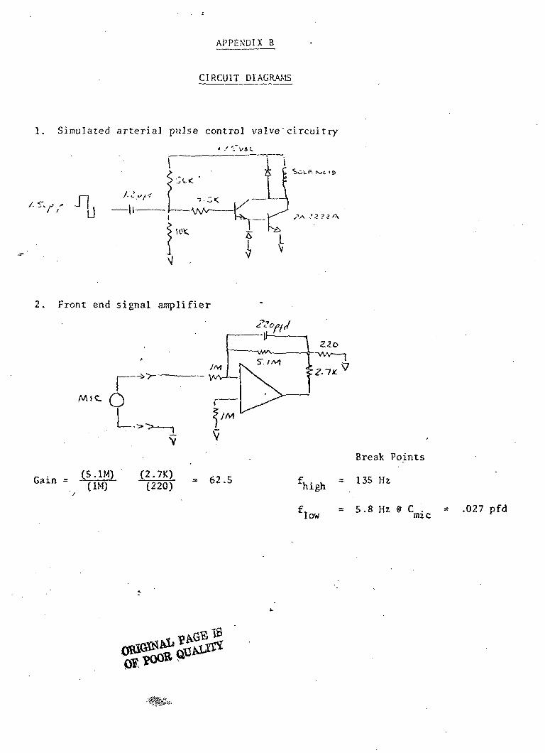
APPENDIX B
CIRCUIT DIAGRAMS
1. Simulated arterial pulse control valve'circuitry
* .' -~l/6C
2. Front end signal amplifier
Break Points
W V135HZ
= .027 pfd
Miniature Battery or 28 VDC
Line-operated Defibrillater/Scope

Miniature Battery or 28 VDC Line-operated Defibrillator/Scope
Major effort was expended on the Defibrillator/Scope. Several meetings on the
subject were held with the Technical Monitor. The results of the configuration
decisions are shown by .the front panel drawing on the next page. The unit
was delivered and has been found to function well.
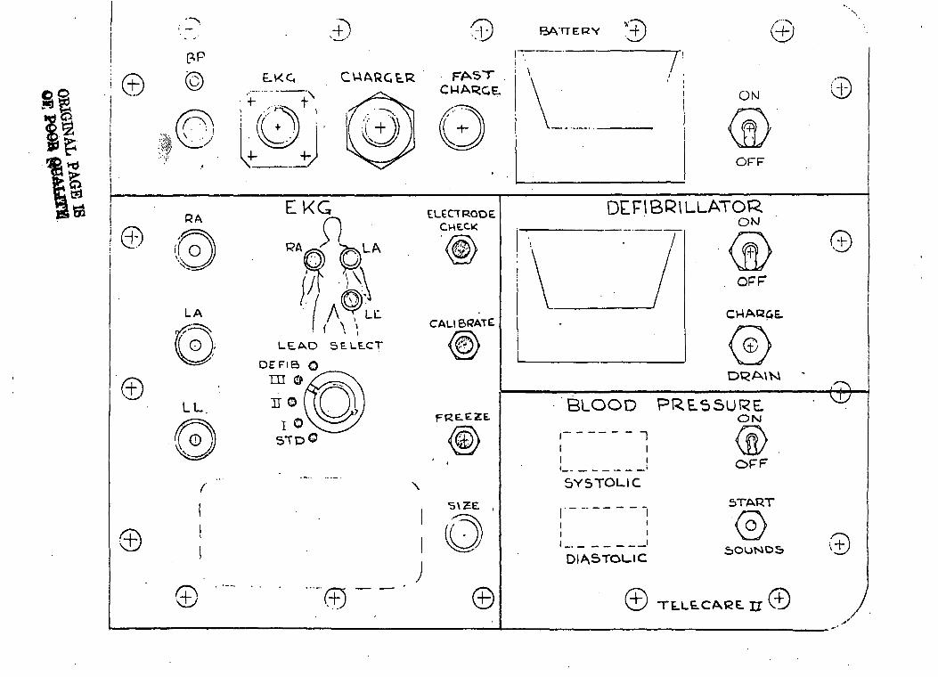
©
Ut1
!..4-
'
©©
SCO
lOoz0
0uJUuJ_JuJh
"i
.4-'
(Cco©
©©