Embed Size (px)
Citation preview
ELE B7 ELE B7 Power Systems Engineering Power Systems Engineering
Power SystemPower System
ComponentsComponents’’
ModelingModeling
Section III : Transformer Model
Slide # 2
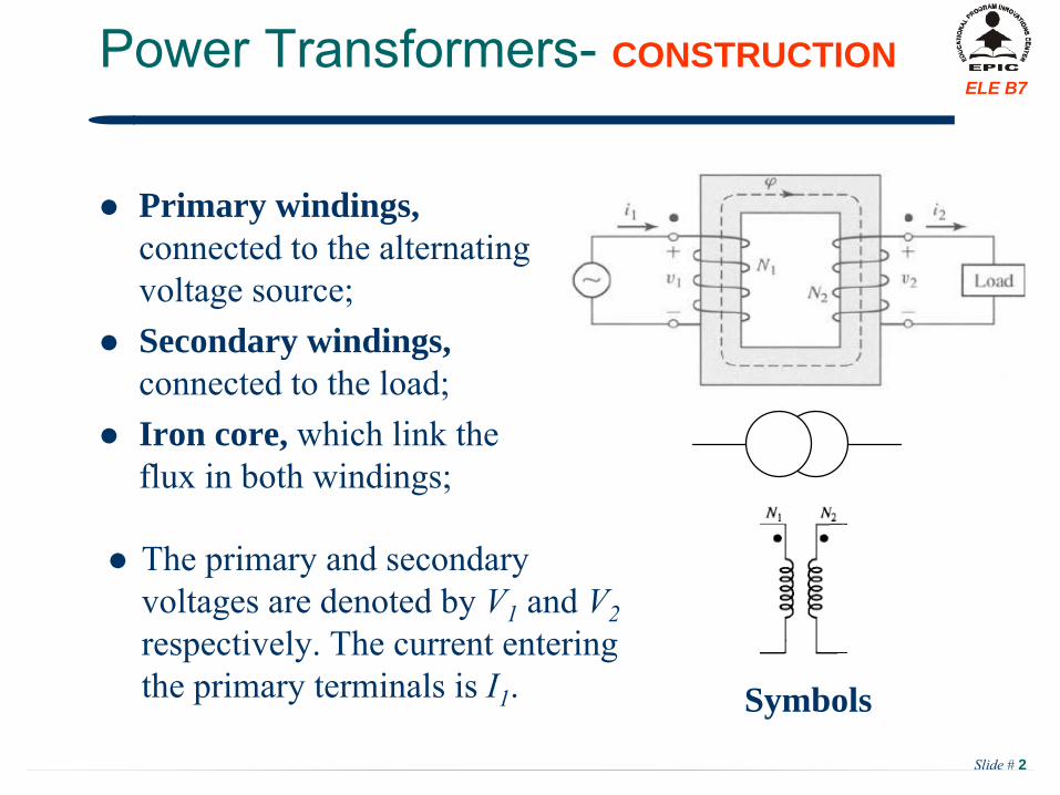
ELE B7Power Transformers-
CONSTRUCTION
Primary windings, connected to the alternating voltage source;
Secondary windings, connected to the load;
Iron core, which link the flux in both windings;
Symbols
The primary and secondary voltages are denoted by V1
and V2
respectively. The current entering the primary terminals is I1
.
Slide # 3
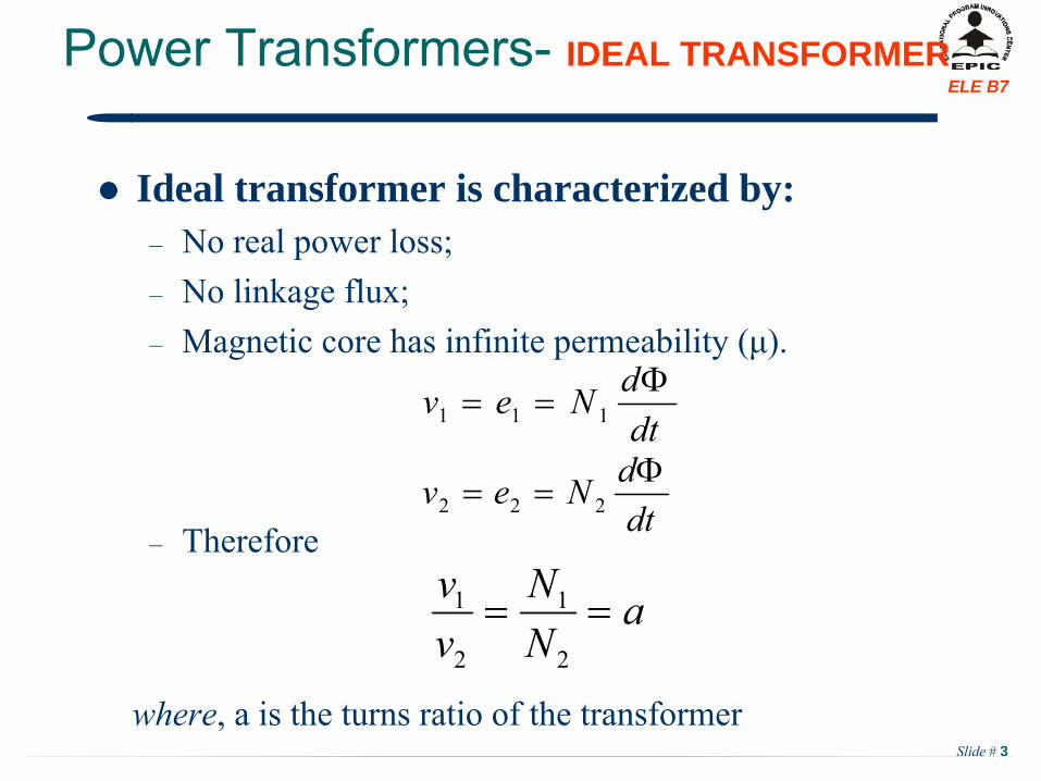
ELE B7Power Transformers-
IDEAL TRANSFORMER
Ideal transformer is characterized by:–
No real power loss;
–
No linkage flux;–
Magnetic core has infinite permeability (μ).
–
Therefore
dtdNev
111
dtdNev
222
aNN
vv
2
1
2
1
where, a is the turns ratio of the transformer
Slide # 4
ELE B7
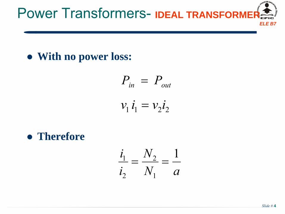
With no power loss:
Therefore
outin PP
2211 iviv
aNN
ii 1
1
2
2
1
Power Transformers-
IDEAL TRANSFORMER
Slide # 5
ELE B7Power Transformers-
REAL TRANSFORMER
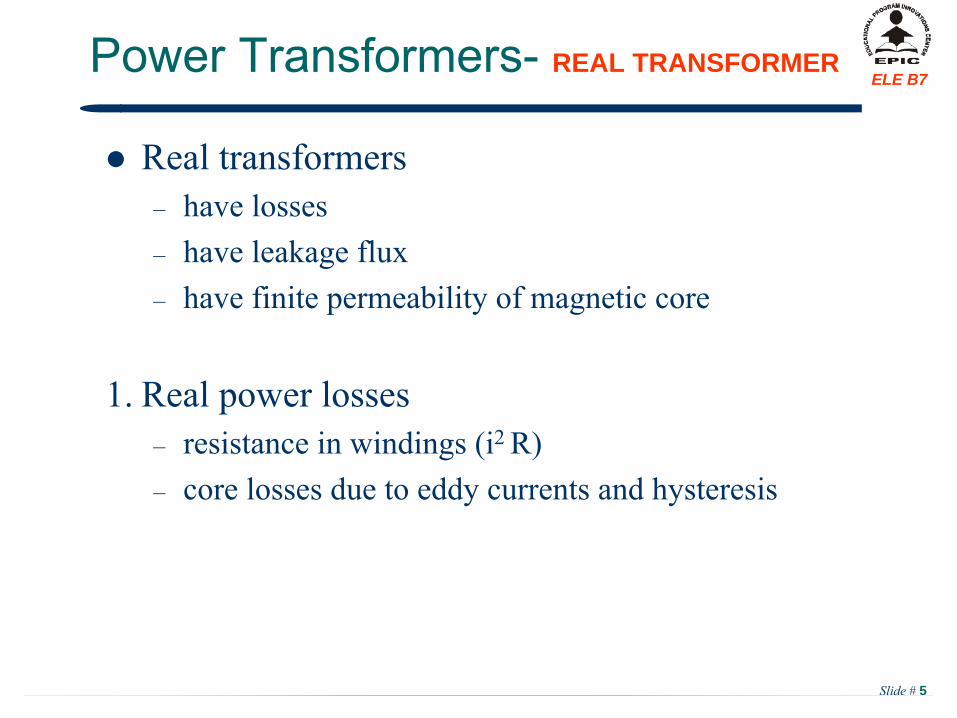
Real transformers–
have losses
–
have leakage flux–
have finite permeability of magnetic core
1.
Real power losses–
resistance in windings (i2 R)
–
core losses due to eddy currents and hysteresis
Slide # 6
ELE B7Power Transformers-
REAL TRANSFORMER
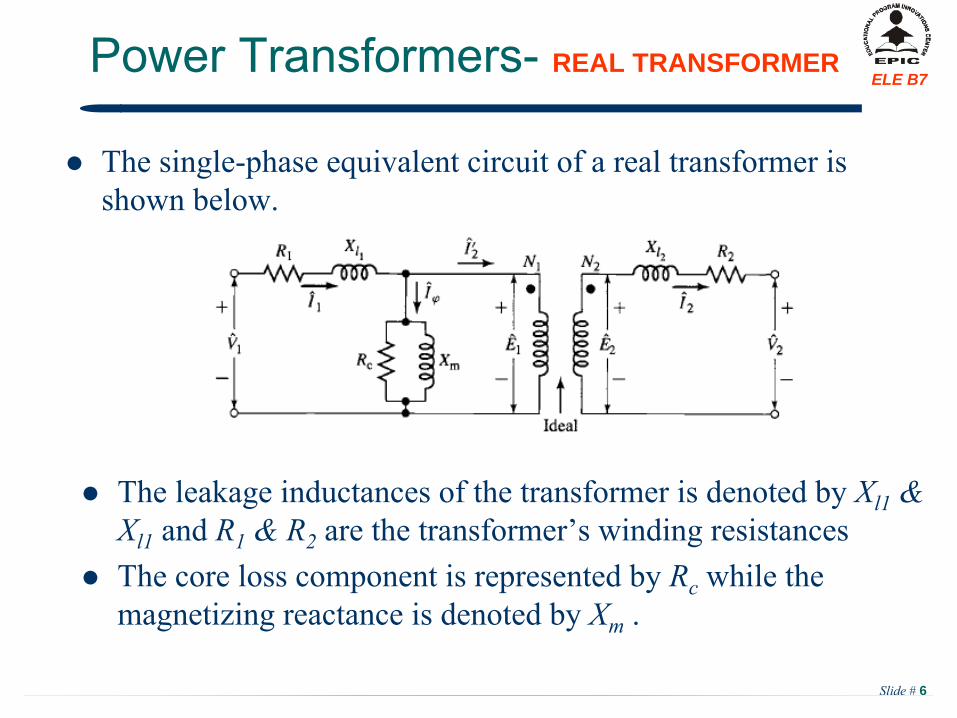
The single-phase equivalent circuit of a real transformer is shown below.
The leakage inductances of the transformer is denoted by Xl1
& Xl1
and R1
& R2
are the
transformer’s winding resistances
The core loss component is represented by Rc
while the magnetizing reactance is denoted by Xm
.
Slide # 7
ELE B7Power Transformers-
Approximate Circuits
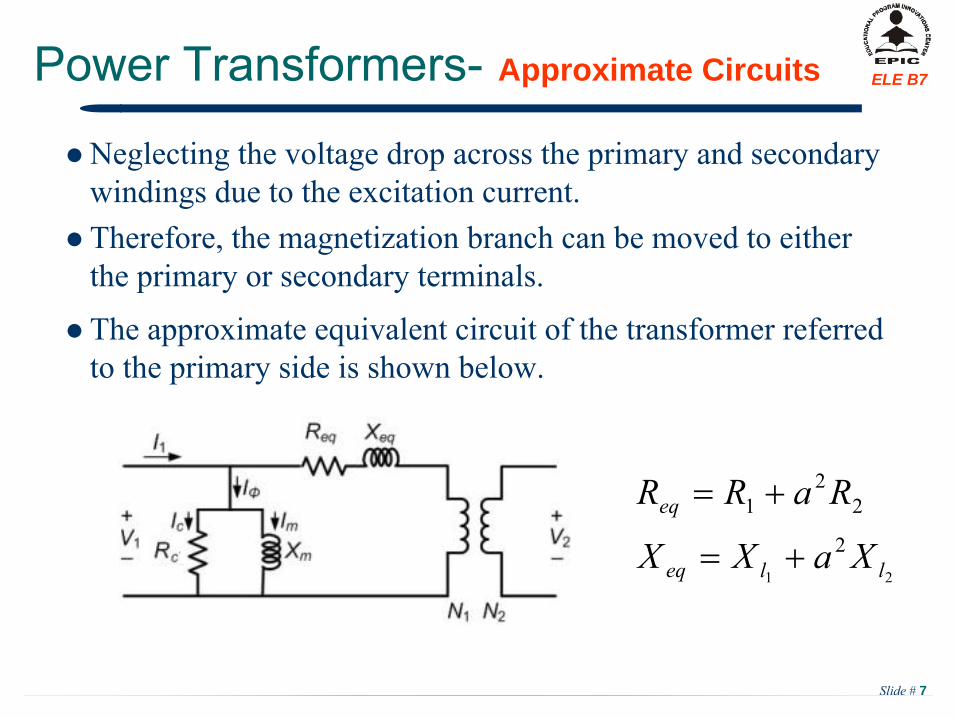
Neglecting the voltage drop across the primary and secondary windings due to the excitation current.
Therefore, the magnetization branch can be moved to either the primary or secondary terminals.
21
2
22
1
lleq
eq
XaXX
RaRR
The approximate equivalent circuit of the transformer referred to the primary side is shown below.
Slide # 8
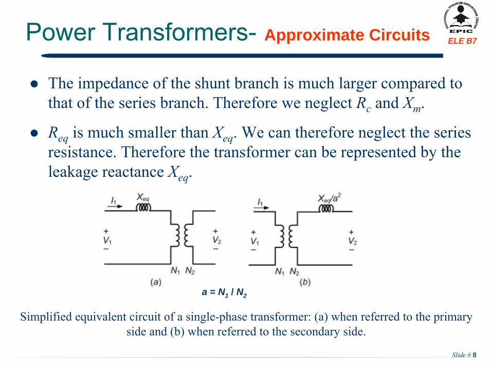
ELE B7Power Transformers-
Approximate Circuits
The impedance of the shunt branch is much larger compared to that of the series branch. Therefore we neglect Rc
and Xm
.
Req
is much smaller than Xeq
. We can therefore neglect the series resistance. Therefore the transformer can be represented by the leakage reactance Xeq
.
Simplified equivalent circuit of a single-phase transformer: (a) when referred to the primary side and (b) when referred to the secondary side.
a = N1 / N2
Slide # 9
ELE B7Power Transformers-
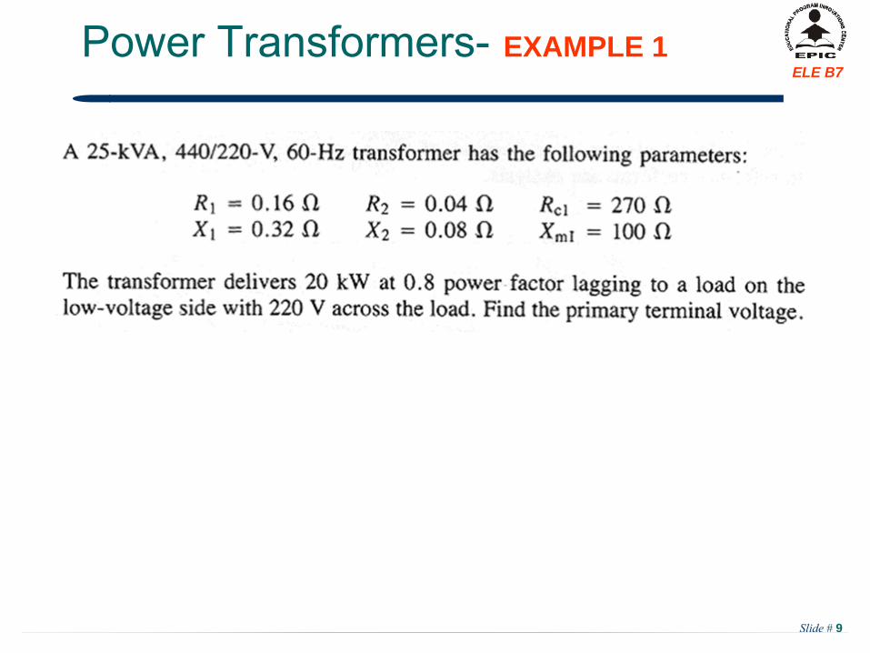
EXAMPLE 1
Slide # 10
ELE B7Power Transformers-
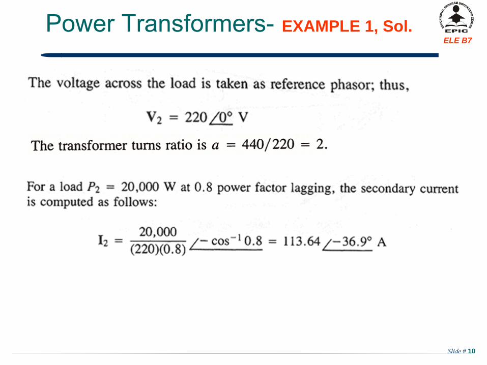
EXAMPLE 1, Sol.
Slide # 11
ELE B7Power Transformers-
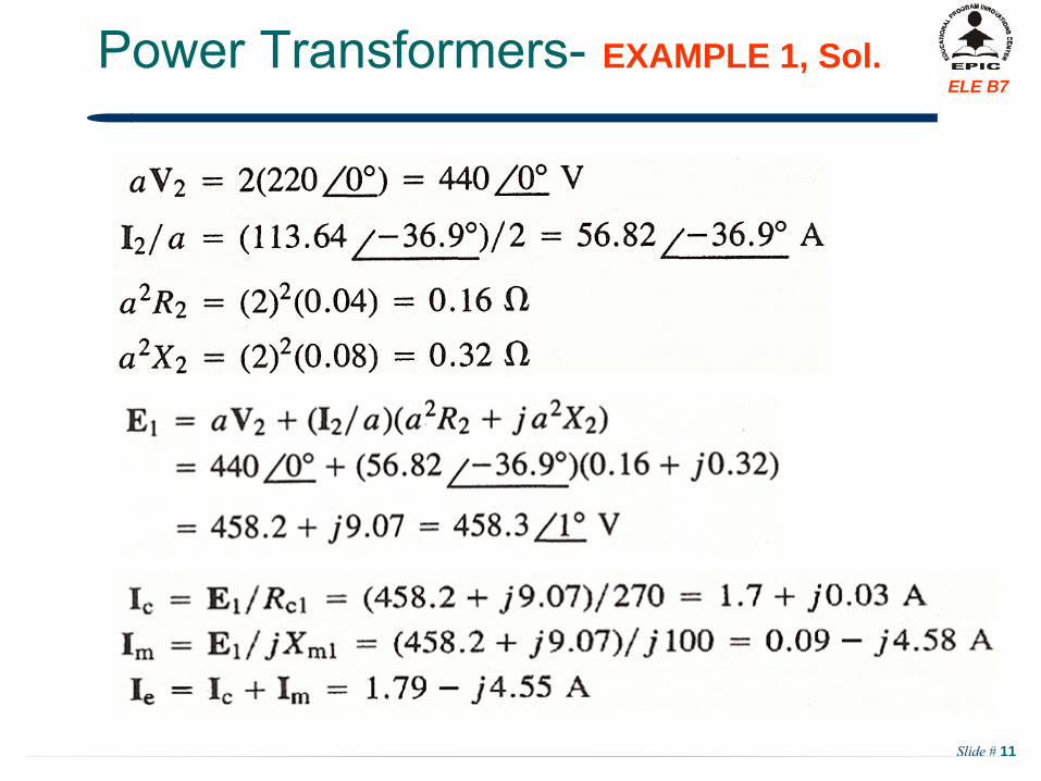
EXAMPLE 1, Sol.
Slide # 12
ELE B7Power Transformers-
EXAMPLE 1, Sol.
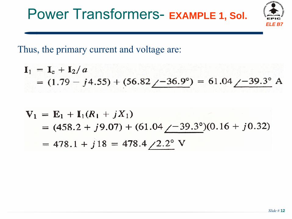
Thus, the primary current and voltage are:
Slide # 13
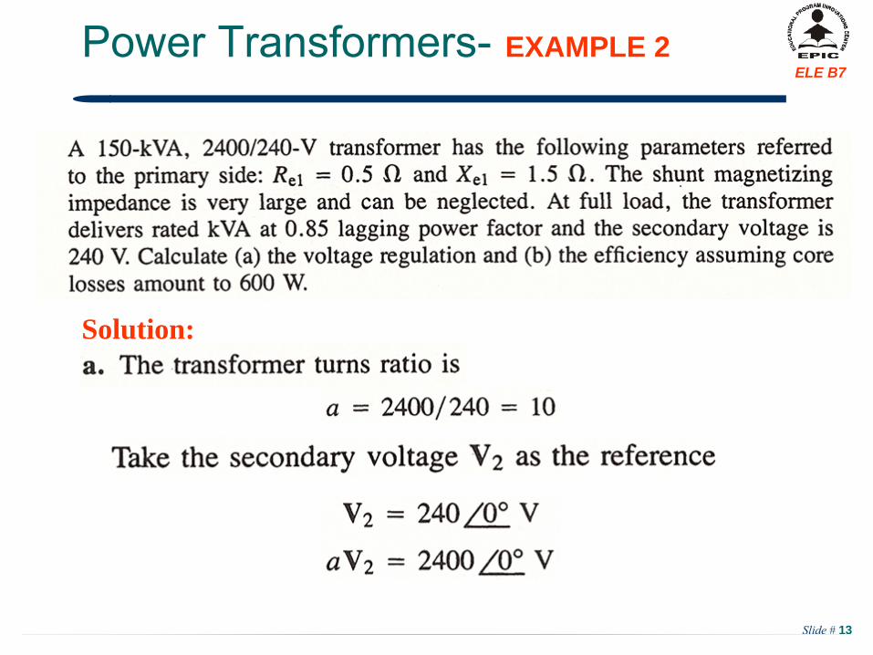
ELE B7Power Transformers-
EXAMPLE 2
Solution:
Slide # 14
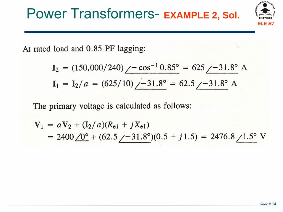
ELE B7Power Transformers-
EXAMPLE 2, Sol.
Slide # 15
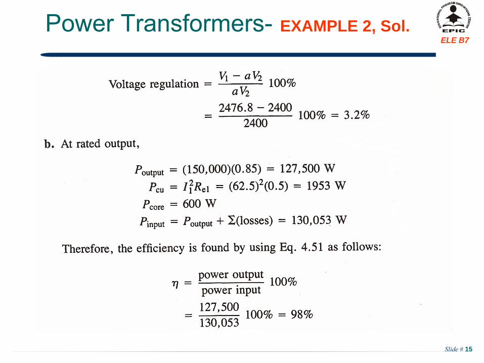
ELE B7Power Transformers-
EXAMPLE 2, Sol.
Slide # 16
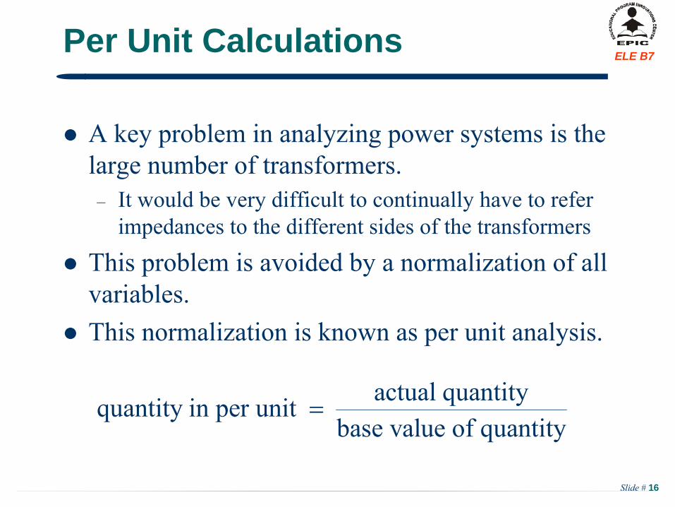
ELE B7Per Unit Calculations
A key problem in analyzing power systems is the large number of transformers.
–
It would be very difficult to continually have to refer impedances to the different sides of the transformers
This problem is avoided by a normalization of all variables.
This normalization is known as per unit analysis.
actual quantityquantity in per unit base value of quantity
Slide # 17
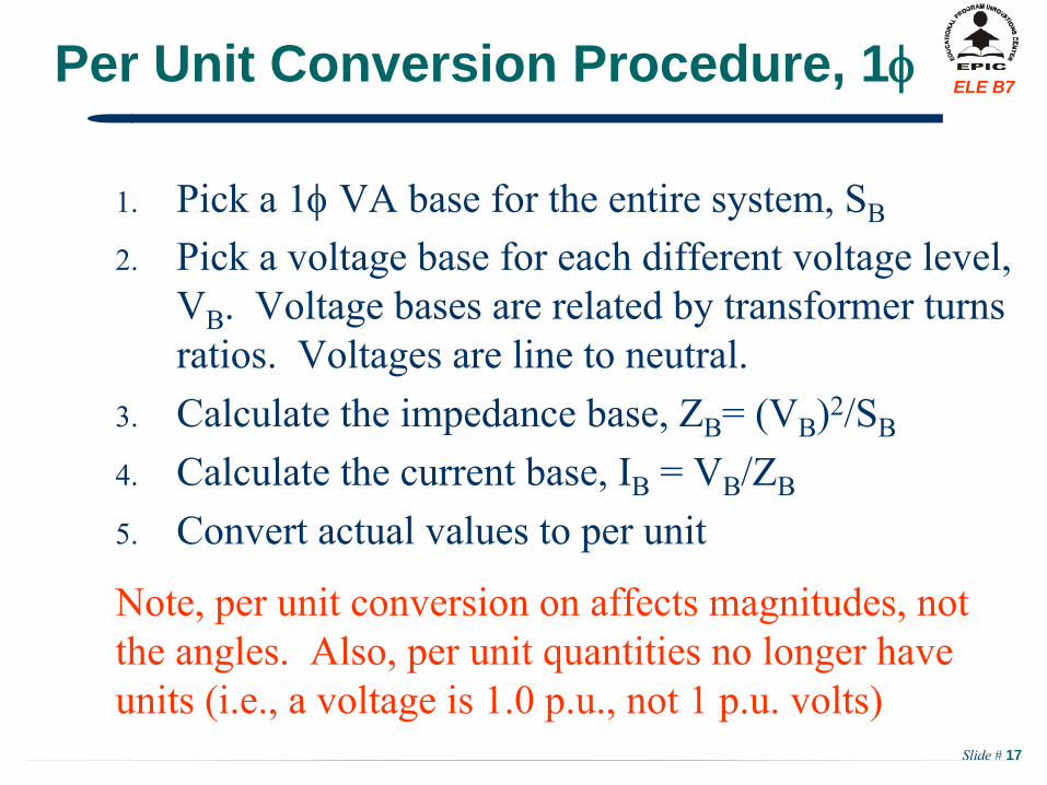
ELE B7Per Unit Conversion Procedure, 1
1.
Pick a 1
VA base for the entire system, SB
2.
Pick a voltage base for each different voltage level, VB
. Voltage bases are related by transformer turns ratios. Voltages are line to neutral.
3.
Calculate the impedance base, ZB
= (VB
)2/SB
4.
Calculate the current base, IB
= VB
/ZB
5.
Convert actual values to per unit
Note, per unit conversion on affects magnitudes, not the angles. Also, per unit quantities no longer have units (i.e., a voltage is 1.0 p.u., not 1 p.u. volts)
Slide # 18
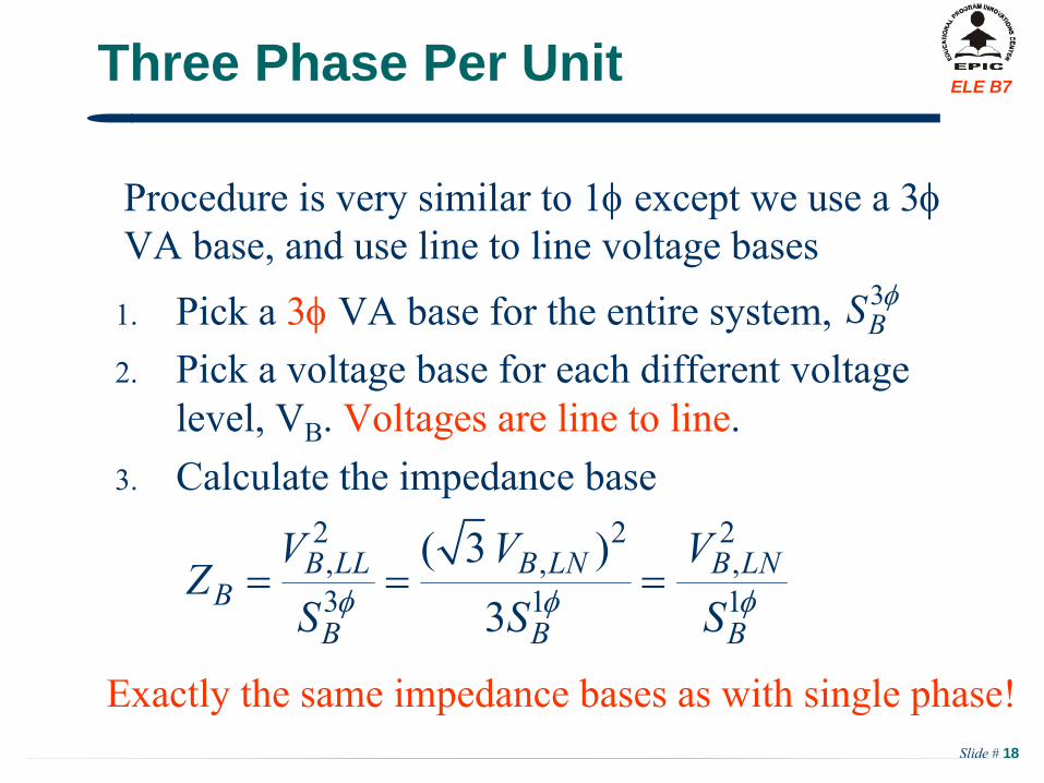
ELE B7Three Phase Per Unit
1.
Pick a 3
VA base for the entire system, 2.
Pick a voltage base for each different voltage level, VB
. Voltages are line to line. 3.
Calculate the impedance base
Procedure is very similar to 1
except we use a 3VA base, and use line to line voltage bases
3BS
2 2 2, , ,3 1 1
( 3 )3
B LL B LN B LNB
B B B
V V VZ
S S S
Exactly the same impedance bases as with single phase!
Slide # 19
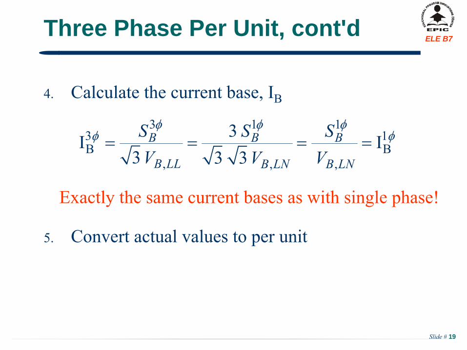
ELE B7Three Phase Per Unit, cont'd
4.
Calculate the current base, IB
5.
Convert actual values to per unit
3 1 13 1B B
, , ,
3I I3 3 3
B B B
B LL B LN B LN
S S SV V V
Exactly the same current bases as with single phase!
Section IV: Synchronous Machine Model
Slide # 21
ELE B7Synchronous Generator-
CONSTRUCTION
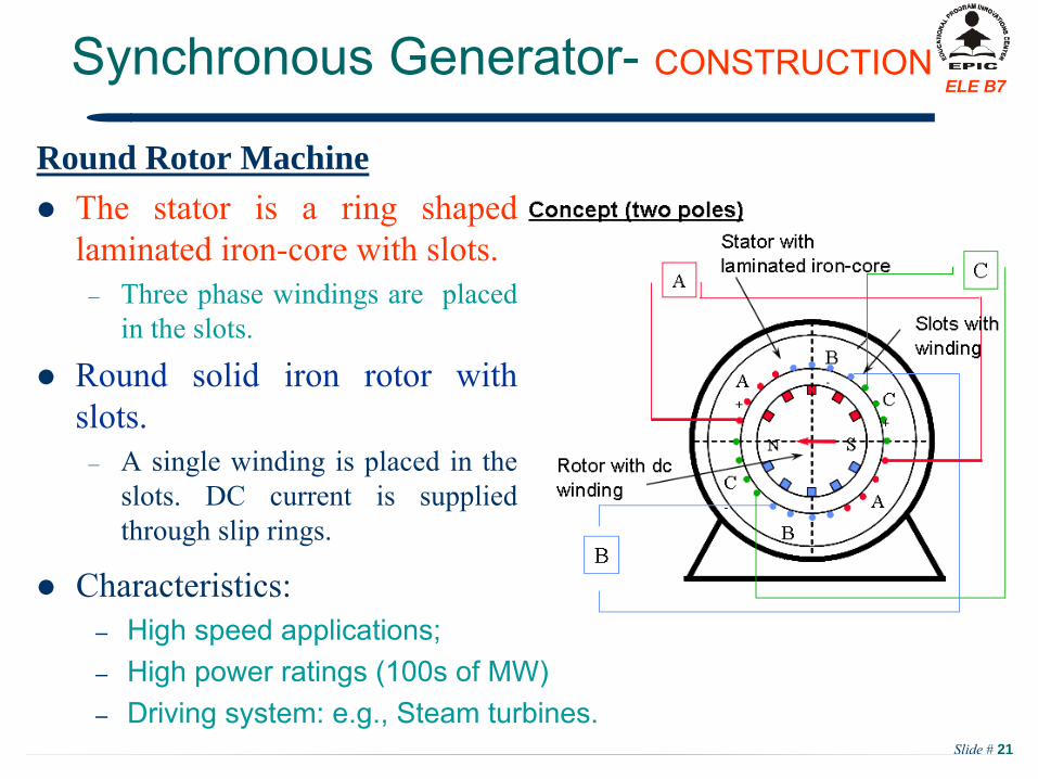
Round Rotor Machine
The stator is a ring shaped laminated iron-core with slots.
–
Three phase windings are placed in the slots.
Round solid iron rotor with slots.
–
A single winding is placed in the slots. DC current is supplied through slip rings.
Characteristics:
–
High speed applications;–
High power ratings (100s of MW)–
Driving system: e.g., Steam turbines.
Slide # 22
ELE B7Synchronous Generator-
CONSTRUCTION
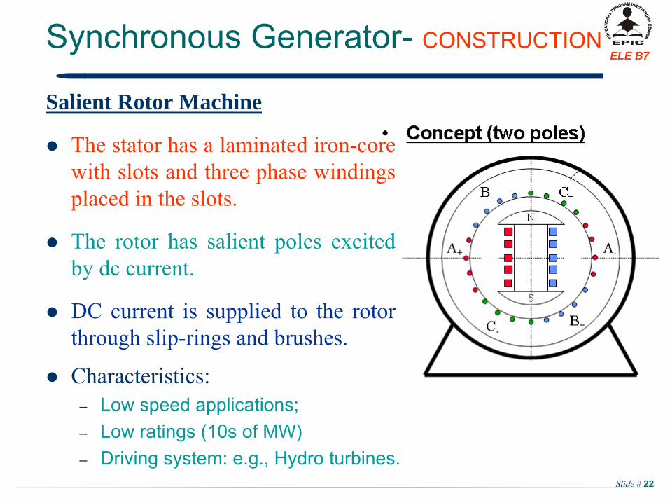
Salient Rotor Machine
The stator has a laminated iron-core with slots and three phase windings placed in the slots.
The rotor has salient poles excited by dc current.
DC current is supplied to the rotor through slip-rings and brushes.
Characteristics:
–
Low speed applications;–
Low ratings (10s of MW)–
Driving system: e.g., Hydro turbines.
Slide # 23
ELE B7
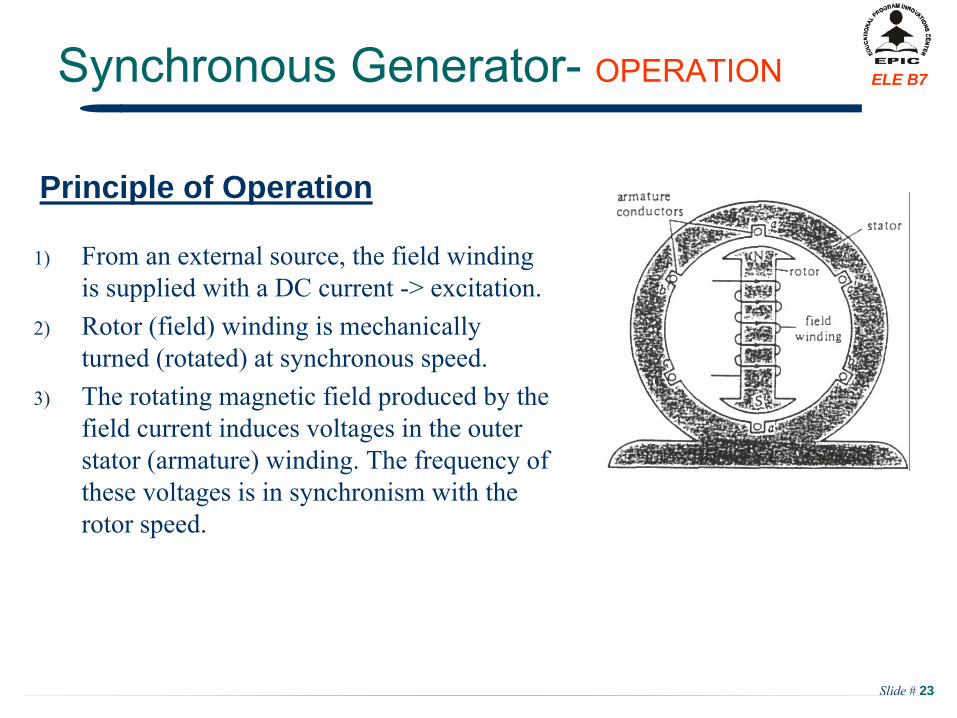
1)
From an external source, the field winding is supplied with a DC current -> excitation.
2)
Rotor (field) winding is mechanically turned (rotated) at synchronous speed.
3)
The rotating magnetic field produced by the field current induces voltages in the outer stator (armature) winding. The frequency of these voltages is in synchronism with the rotor speed.
Principle of Operation
Synchronous Generator-
OPERATION
Slide # 24
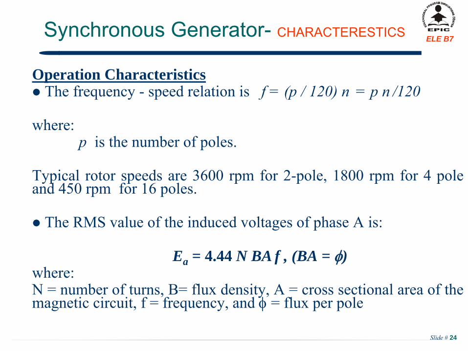
ELE B7
Operation Characteristics The frequency -
speed relation is f = (p / 120) n
= p n
/120
where:p
is the number of poles.
Typical rotor speeds are 3600 rpm for 2-pole, 1800 rpm for 4 pole and 450 rpm for 16 poles.
The RMS value of the induced voltages of phase A is:
Ea = 4.44 N BA f , (BA = )where:N = number of turns, B= flux density, A = cross sectional area of the magnetic circuit, f = frequency, and
= flux per pole
Synchronous Generator-
CHARACTERESTICS
Slide # 25
ELE B7
Round Rotor Type1)
DC current in the field winding produces the main flux, f .2)
f
induces an emf, Ea , in the armature winding. 3)
Depending on the load condition, the armature current
IA is established. In the following discussions, it is assumed to be a
lagging power factor.4) IA produces its own flux due to armature reaction, EAR is the
induced emf
by AR .5)
The resulting phasor, Eresultant = Ea + EAR is the “true”
induced emf
that is available.
Synchronous Generator-
Equivalent Circuit
Slide # 26
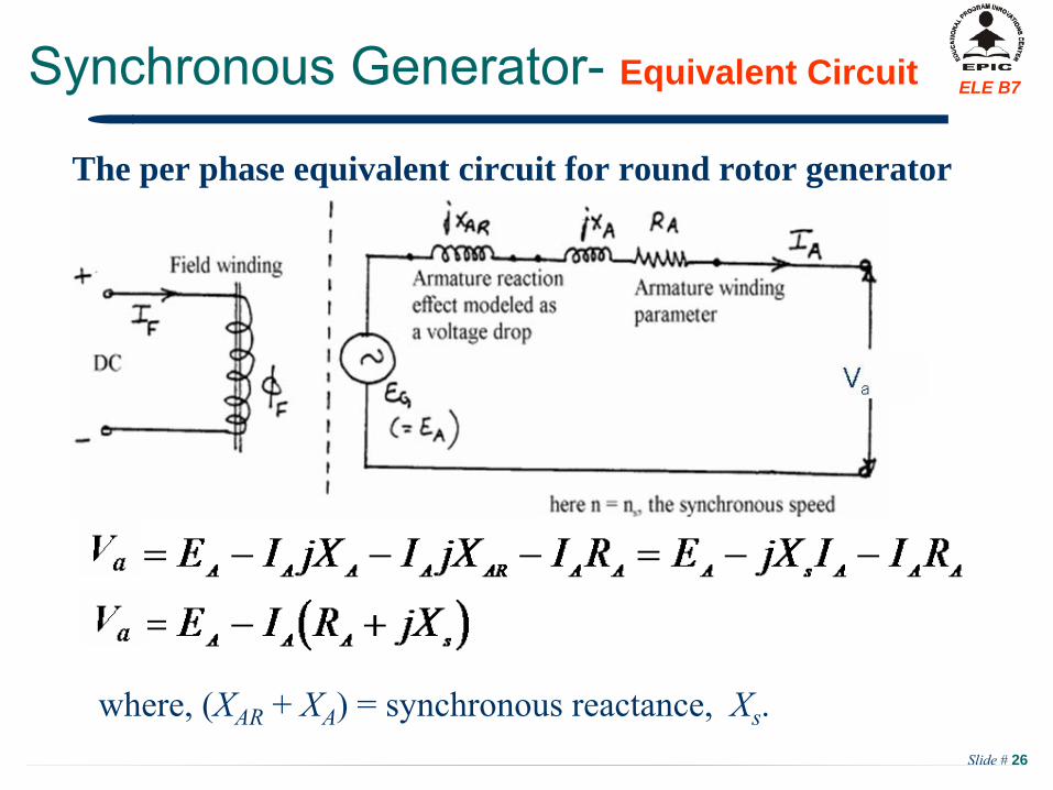
ELE B7Synchronous Generator-
Equivalent Circuit
The per phase equivalent circuit for round rotor generator
where, (XAR
+ XA
) = synchronous reactance, Xs
.
Slide # 27
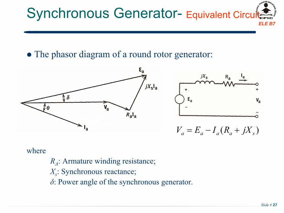
ELE B7Synchronous Generator-
Equivalent Circuit
The phasor diagram of a round rotor generator:
whereRA
: Armature winding resistance;Xs
: Synchronous reactance;δ: Power angle of the synchronous generator.
)( saaaa jXRIEV
Slide # 28
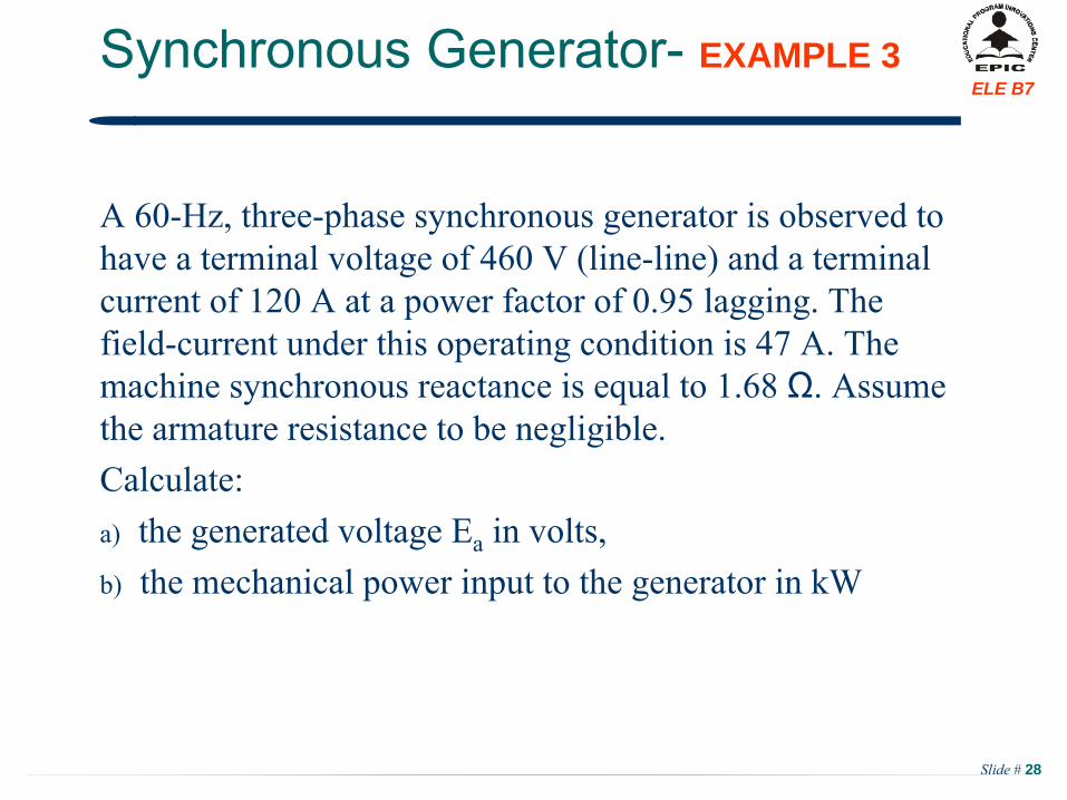
ELE B7Synchronous Generator-
EXAMPLE 3
A 60-Hz, three-phase synchronous generator
is observed to have a terminal voltage of 460 V
(line-line) and a terminal
current of 120 A at a power factor of 0.95 lagging. The field-current
under this operating condition is 47 A. The
machine synchronous reactance is equal to 1.68 Ω. Assume the armature resistance to be
negligible.
Calculate:a) the generated voltage Ea
in volts,b) the mechanical
power input to the generator
in kW
Slide # 29
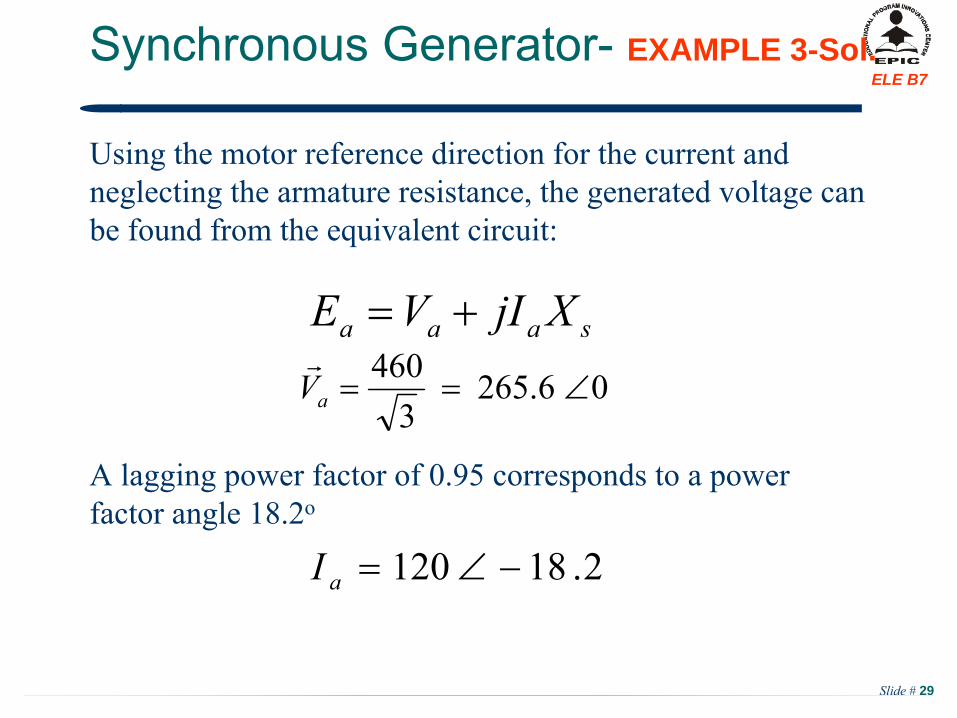
ELE B7Synchronous Generator-
EXAMPLE 3-Sol.
Using the motor reference direction for the current and neglecting the armature resistance,
the generated voltage can
be found from the equivalent circuit:
A lagging power factor of 0.95 corresponds to a power factor angle 18.2o
saaa XjIVE
06.2653
460aV
2.18120 aI
Slide # 30
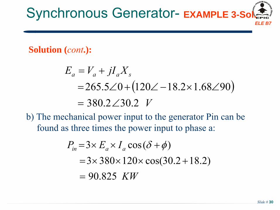
ELE B7Synchronous Generator-
EXAMPLE 3-Sol.
Solution (cont.):
b) The mechanical power input to the generator Pin can be found as three times the power input to phase a:
V
XjIVE saaa
2.302.3809068.12.1812005.265
KW
IEP aain
825.90)2.182.30cos(1203803
)(cos3
Slide # 31
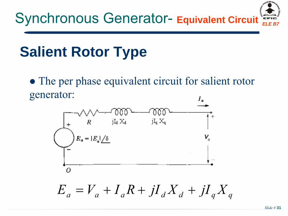
ELE B7Synchronous Generator-
Equivalent Circuit
The per phase equivalent circuit for salient rotor generator:
qqddaaa XjIXjIRIVE
Salient Rotor Type
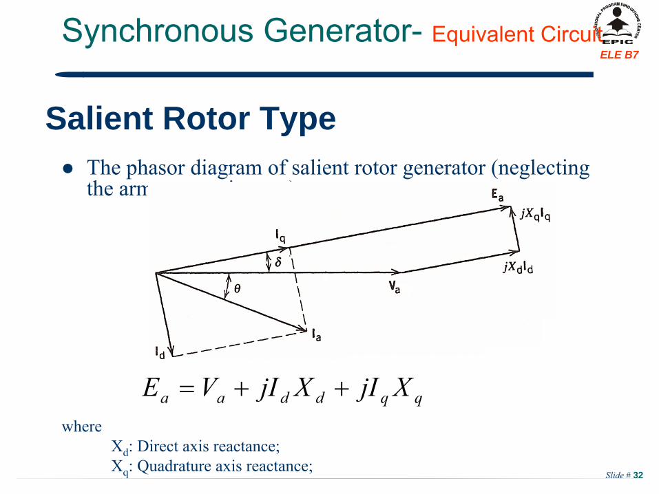
Slide # 32
ELE B7
The phasor diagram of salient rotor generator (neglecting the armature resistance):
whereXd
: Direct axis reactance;Xq
: Quadrature axis reactance;
Synchronous Generator-
Equivalent Circuit
qqddaa XjIXjIVE
Salient Rotor Type
Slide # 33
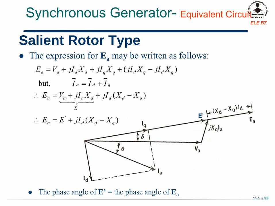
ELE B7Synchronous Generator-
Equivalent Circuit
)(
)(,but
)(
'
'
qdda
qdd
E
qaaa
qda
qdqdqqddaa
XXjIEE
XXjIXjIVEIII
XjIXjIXjIXjIVE
Salient Rotor Type
The expression for Ea may be written as follows:
The phase angle of E’ = the phase angle of Ea
Slide # 34
ELE B7Synchronous Generator-
EXAMPLE 4
Slide # 35
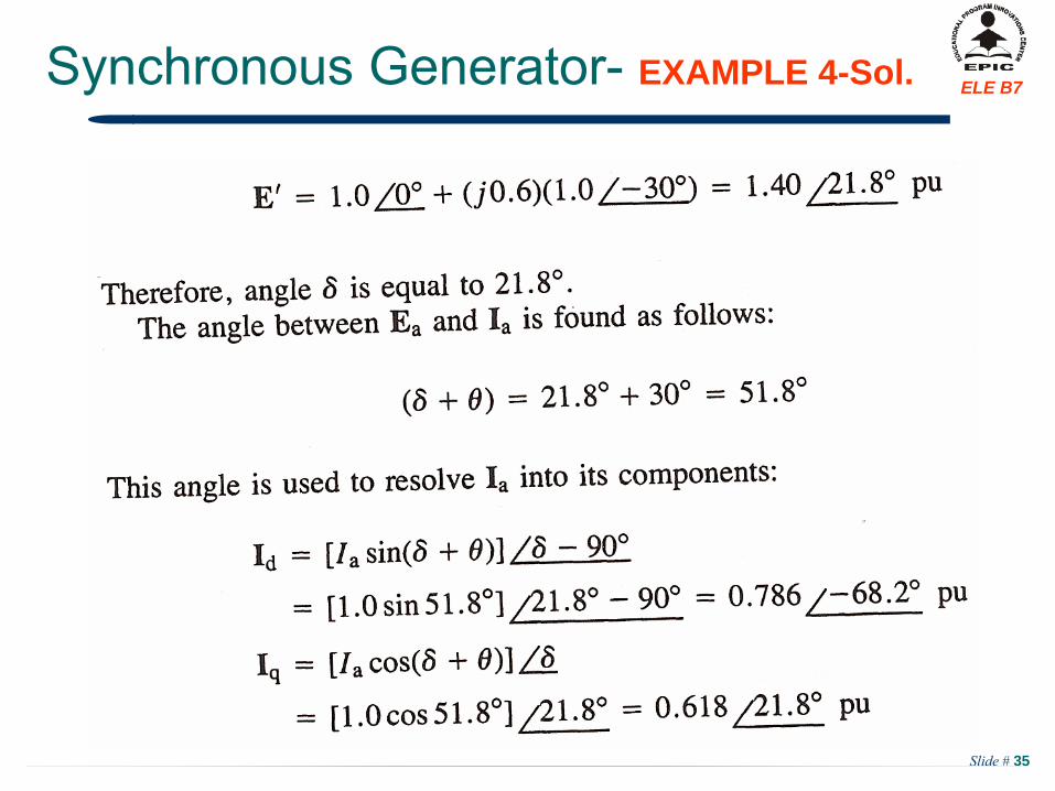
ELE B7Synchronous Generator-
EXAMPLE 4-Sol.
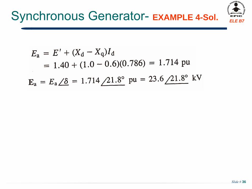
Slide # 36
ELE B7Synchronous Generator-
EXAMPLE 4-Sol.
Slide # 37
ELE B7Synchronous Generator-
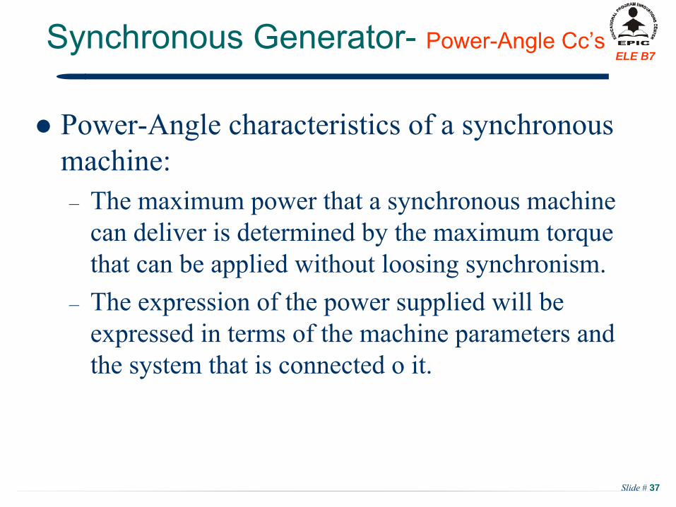
Power-Angle Cc’s
Power-Angle characteristics of a synchronous machine:–
The maximum power that a synchronous machine can deliver is determined by the maximum torque that can be applied without loosing synchronism.
–
The expression of the power supplied will be expressed in terms of the machine parameters and the system that is connected o it.
Slide # 38
ELE B7Synchronous Generator-
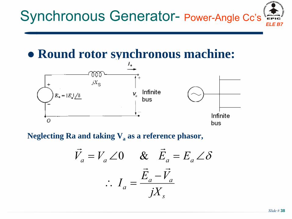
Power-Angle Cc’s
Round rotor synchronous machine:
Neglecting Ra and taking Va as a reference phasor,
s
aaa
aaaa
jXVEI
EEVV
&0
Slide # 39
ELE B7Synchronous Generator-
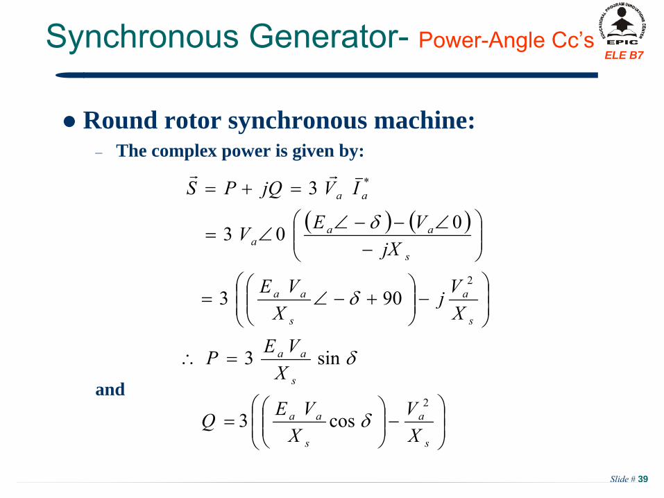
Power-Angle Cc’s
Round rotor synchronous machine:–
The complex power is given by:
and
s
a
s
aa
s
aa
s
a
s
aa
s
aaa
aa
XV
XVEQ
XVEP
XVj
XVE
jXVEV
IVjQPS
2
2
*
cos3
sin3
903
003
3
Slide # 40
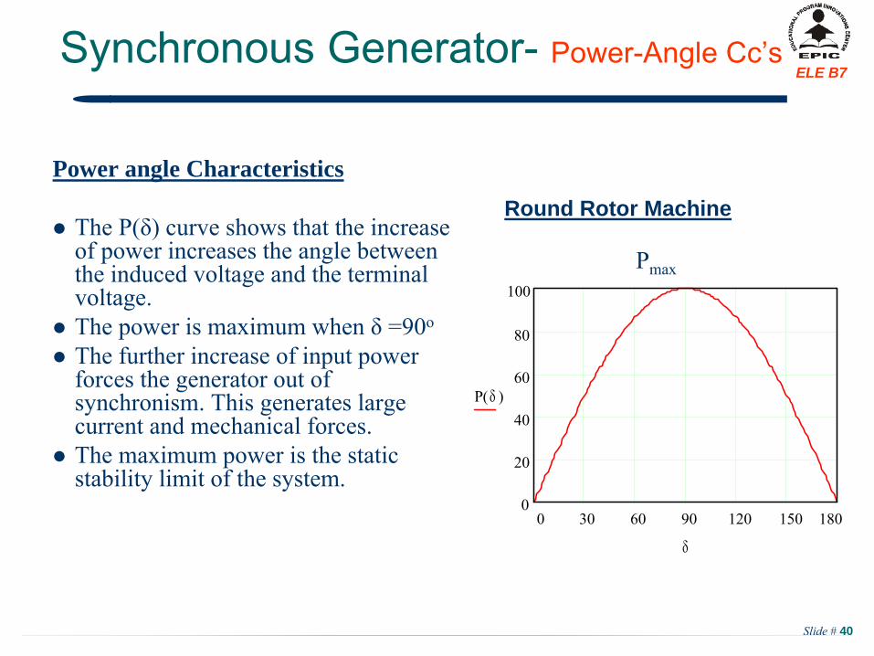
ELE B7Synchronous Generator-
Power-Angle Cc’s
Power angle Characteristics
The P(δ) curve shows that the increase of power increases the angle between the induced voltage and the terminal voltage.
The power is maximum when δ
=90o
The further increase of input power forces the generator out of synchronism. This generates large current and mechanical forces.
The maximum power is the static stability limit of the system.
Round Rotor Machine
0 30 60 90 120 150 1800
20
40
60
80
100
P( )
Pmax
Slide # 41
ELE B7Synchronous Generator-
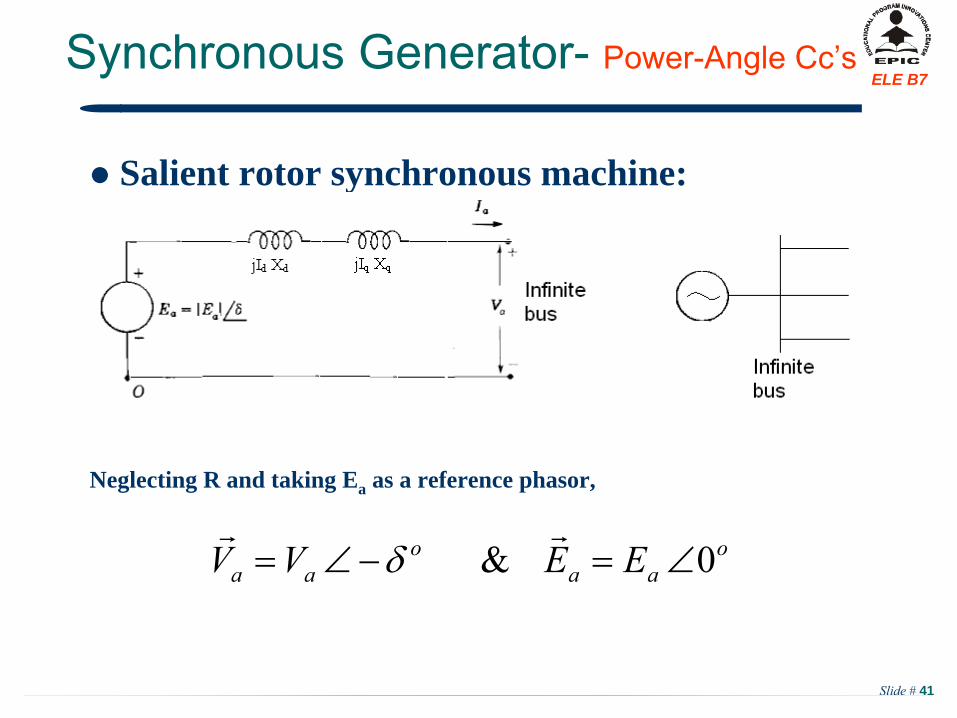
Power-Angle Cc’s
Salient rotor synchronous machine:
Neglecting R and taking Ea as a reference phasor,
oaa
oaa EEVV 0&
Slide # 42
ELE B7Synchronous Generator-
Power-Angle Cc’s
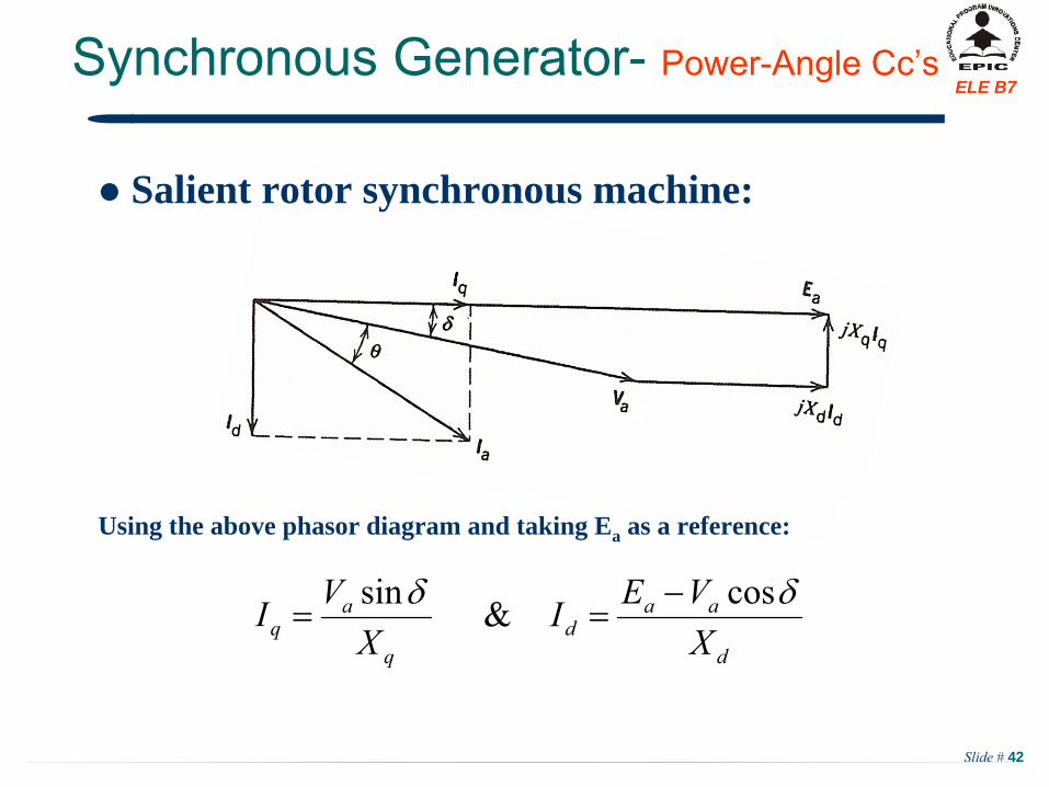
Salient rotor synchronous machine:
Using the above phasor diagram and taking Ea as a reference:
d
aad
q
aq X
VEIX
VI cos&sin
Slide # 43
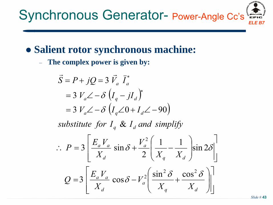
ELE B7Synchronous Generator-
Power-Angle Cc’s
Salient rotor synchronous machine:–
The complex power is given by:
dqa
d
aa
dq
a
d
aa
dq
dqa
dqa
aa
XXV
XVEQ
XXV
XVEP
simplifyandIIforsubstitute
IIV
jIIV
IVjQPS
222
2
*
*
cossincos3
2sin112
sin3
&
9003
3
3
Slide # 44
ELE B7Synchronous Generator-
Power-Angle Cc’s
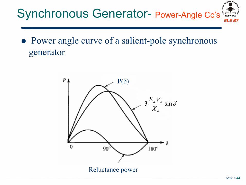
Power angle curve of a salient-pole synchronous generator
P(δ)
Reluctance power
sin3d
aa
XVE
Slide # 45
ELE B7Synchronous Generator-
Power-Angle Cc’s
Salient rotor synchronous machine:
Observations:–
The first term of the active power is identical to the power delivered by a round rotor synchronous generator;
–
The second term represents the effect of generator saliency, and it is called reluctance power;
–
In salient pole machine, Xd
> Xq. When a salient machine approaches a round rotor, the values of Xd
& Xq
will both approach Xs
and P &Q of salient pole machine are reduced to that of round rotor machine.
Slide # 46
ELE B7Synchronous Generator-
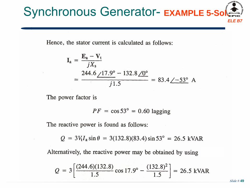
EXAMPLE 5
A 25 kVA, 230 V three phase, four pole, 60 Hz, Y-connected synchronous generator has a synchronous reactance of 1.5 /phase and a negligible armature resistance. The generator is connected
to
an infinite bus of constant voltage (230 V) and frequency (60 Hz), find:a.
The generated EMF (Ea
) when the machine is delivering rated kVA
at 0.8 power factor lagging.
b.
If the field current If
is increased by 20 % without changing the power input find the stator current Ia
.c.
With the field excitation current If
as in part (a), the input power from prime mover is increased very slowly. What is the steady state limit? Determine the stator current Ia
, power factor, and reactive power
Slide # 47
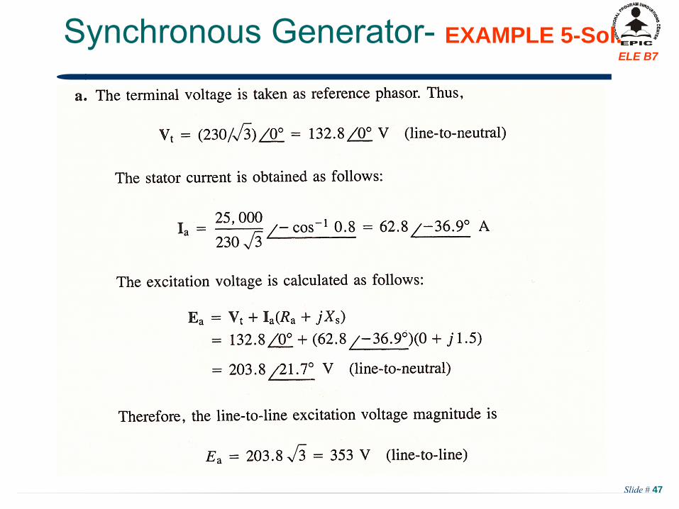
ELE B7Synchronous Generator-
EXAMPLE 5-Sol.
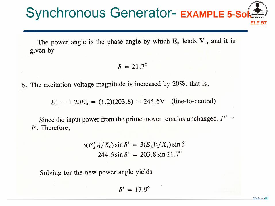
Slide # 48
ELE B7Synchronous Generator-
EXAMPLE 5-Sol.
Slide # 49
ELE B7Synchronous Generator-
EXAMPLE 5-Sol.
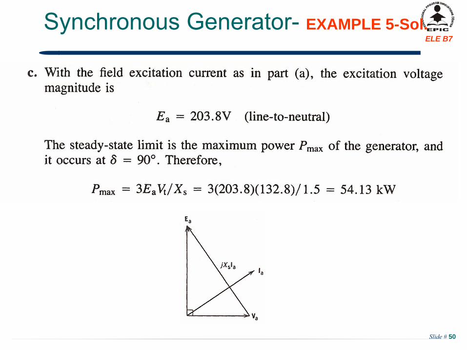
Slide # 50
ELE B7Synchronous Generator-
EXAMPLE 5-Sol.

Slide # 51
ELE B7Synchronous Generator-
EXAMPLE 5-Sol.
From the previous phasor diagram,
Slide # 52
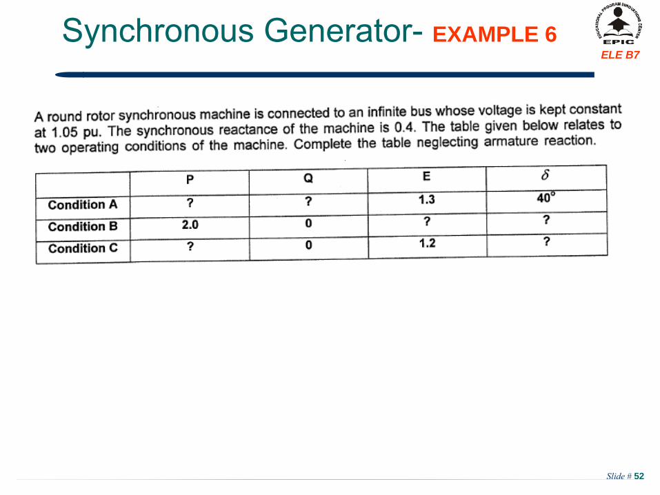
ELE B7Synchronous Generator-
EXAMPLE 6
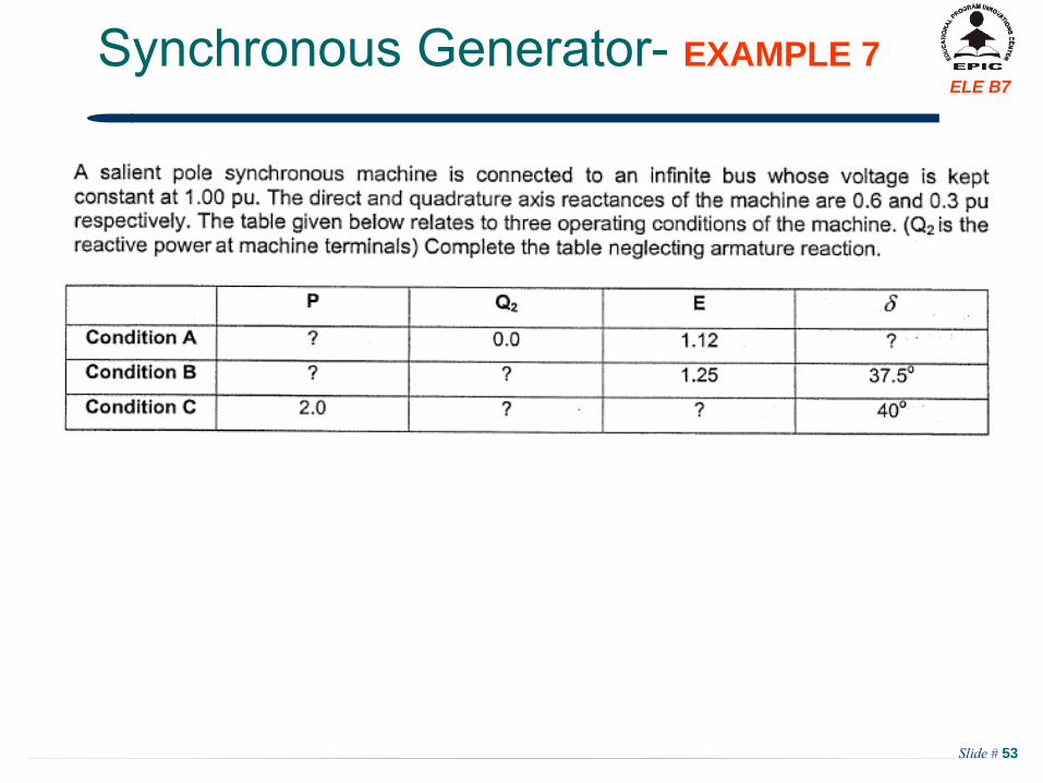
Slide # 53
ELE B7Synchronous Generator-
EXAMPLE 7