Embed Size (px)
Citation preview
NORTHERN WATER SERVICES BOARD
ELDAS - ANOLE WATER SUPPLY
CONTRACT NO. NWSB/T/CW/039/2015-2016
VOLUME 11
SPECIFICATIONS AND
HYDROGEOLOGICAL
SURVEYS
JUNE 2016
,
EMPLOYER: Chief Executive Officer Northern Water Services Board, P. O. Box 495, GARISSA
PROJECT MANAGER: Technical Services Manager Northern Water Services Board P. O. Box 495 GARISSA
1
TABLE OF CONTENTS
STANDARD TECHNICAL SPECIFICATIONS
1 GENERAL SPECIFICATIONS
1.1 Introduction
1.2 Extent of Contract
1.3 Precedence of Contract Documents
1.4 Standards
1.5 Quality of Materials and Workmanship
1.6 Trade Names
1.7 Samples
1.8 Testing
1.9 Programme for Execution of works
1.10 Substantial (Practical Completion)
1.11 Nominated Sub-contractors and Nominated Suppliers
1.12 Entry upon Land, working site and adjoining lands
1.13 Preservation of survey beacons
1.14 Land for camp sites
1.15 Existing Services
1.16 Damage to services
1.17 Temporary Roads and traffic control
1.18 Road closure
1.19 Road & Railway crossing and traffic control
1.20 Protection from water
1.21 Weather Conditions
1.22 Protection from weather
1.23 Explosives and blasting
1.24 Liaison with Police
1.25 Provision of water
1.26 Temporary lighting and power
1.27 Sanitation
1.28 Medical facilities
1.29 Signboards
1.30 Setting out and survey equipment
1.31 Backfilling of Holes and Trenches
1.32 Inspection of works
1.33 Testing of Water-Retaining structures
1.34 Testing of Roofs
1.35 Cleaning and sterilization of water-retaining structure
1.36 Contractor's Superintendence
1.37 Normal Working Hours

2
1.38 Compliance with statutes and Local Regulations
1.39 Accommodation for workmen
1.40 Storage Spaces and sheds
1.41 Office for Contractor
1.42 Office for Engineer's Representative
1.43 Telephone
1.44 Housing for Resident staff
1.45 Maintenance of Resident staff housing, furniture and Equipment
1.46 Attendance upon Resident Engineer and his staff
1.47 Insurance
1.48 Transports for Engineer's Representative
1.49 Removal of Camps
1.50 Site Meetings
2 SITE CLEARANCE
2.1 Clearance of Trees, Bushes
2.2 Damage to lands
2.3 Clearing the site on completion
3 EARTHWORKS
3.1 General
3.2 Classification of Excavations
3.3 Stripping of Top soil
3.4 Excavation in open cut
3.5 Borrow Pits
3.6 Hardcore Filling
3.7 Earth Filling
3.8 Grass Planting and Topsoil
3.9 Anti-Proofing
4 CONCRETE WORKS
4.1 General
4.2 Materials and tests
4.3 Pre-cast concrete units
4.4 Workmanship
5 BUILDERS WORK
5.1 Cocrete Block walling
5.2 Plasterwork and other floor wall and ceiling finishes
3
5.3 Carpentry and joinery
5.4 Roofing
5.5 Steelwork
5.6 Ironmongery and other fittings
5.7 Glazing
5.8 Painting, Decorating and other surface treatment
6 PIPEWORK
6.1 Materials
6.2 Handling and storing materials
6.3 Excavation of trenches
6.4 Laying and jointing
6.5 Concrete manholes and plot chambers
6.6 Testing
6.7 Refilling of Trenches
7 PLUMBING AND DRAINAGE
7.1 General
7.2 Plumbing
8 ROAD WORKS AND FOOTPATHS
8.1 General
8.2 Roads and paved areas
8.3 Fencing
9 MECHANICAL INSTALLTIONS
9.1 General
9.2 Spare Parts
9.3Storage of Materials
9.4 Description of services
9.5 Maintenance Manual
9.6 Motors
9.7 Engines
9.8 Pumps
9.9 Chemicals Dosing Equipment
9.10 Pressure Gauges
10 ELECTRICAL WORKS

4
10.1 General
10.2 Regulations
10.3 Materials
10.4 Workmanship
10.5 Main Switchboard
10.6 Switchgear
10.7 Motor starters
10.8 Wiring
10.9 Cable and conductors
10.10 Conduits
10.11 Boxes
10.12 Light fittings
10.13 Light switches
10.14 Power Installation
10.15 Earthing and Bonding
10.16 Testing
10.17 Handing over
11 DRILLING OF BOREHOLES
12 SHALLOW WELLS
5
STANDARD TECHNICAL SPECIFICATIONS
1 GENERAL SPECIFICATIONS
1.1 Introduction
These specifications cover the construction of the works as shown on the drawings and listed in the
Bills of Quantities and shall be read in conjunction with the contract documents as listed in
volume 1, instructions to Tenderer.
All references given are intended solely for the convenience of those using the above clauses in the
documents, which may, in the opinion of the Engineer have any bearing on the point in
question.
1.1.1 Location
The location of the works is described in volume 1.
1.1.2Scope of Works
The scope of the works is described in volume 1 and in the specific drawings.
1.2Extent of Contract
The works specified under this contract shall include all general works preparatory to the
construction of the works and materials and work of any kind necessary
1.3 Precedence of Contract Documents
Should the provisions of any clauses of any or all of the Contract Document to be shown to be
mutually at variance or exclusive, the following order of precedence shall be applied in
order to establish which of the said provisions, mutually at variance or exclusive, shall be
deemed to be true and correct intent of the contract entered into by Employer, and the
contractor shall forthwith be absolved from any liability under the provisions not so proved
to be the true and correct intent of the contact, provided that in the execution of the contract
the contractor has, or shall have complied with such true and correct intent.
(i) Provision of the Standard or Special Specifications shall take precedence over those of the
General Conditions of Contract.
(ii) Provision of volume 1 shall take precedence over the standard specifications unless otherwise
indicated.

6
(iii) Details shown or noted on the contract drawings shall take precedence over the requirements of
both the standard and volume 1.
(iv) Detail drawing shall take precedence over General Drawings.
(v) Within the Standard Specifications, the provisions of any section particular to the provisions at
variance shall take precedence over the general section, and within any section
clauses particular to the provisions at variance shall take precedence over those not
so particular. The foregoing order of precedence shall apply also to sections and
clauses of the special specifications.
(vi) Where there is conflict in units of measurement quoted in standard specifications and units
quoted in Bills of Quantities the units in latter will apply.
Notwithstanding any fore written provisions, should the application of the foregoing order of
precedence fail to resolve any variance or mutual exclusions as to the true and correct intent
of the contract to the satisfaction of the Engineer, the Engineer may exercise the right to
arbitrarily give a ruling as to the true and correct intention of the contract, and the contractor
shall have the right to claim additional payment for any additional expense incurred by him
as a consequence of such variance or exclusion and arbitrary ruling.
1.4Standards
In the specifications, Bills of Quantities, and Drawings reference has been made to relevant British
Standard Specifications and Codes of Practice- to which the materials and workmanship
should comply with. However, the materials and workmanship complying with equivalent
Kenya Bureau of Standards (K.B.S) or International Standards Organisation (I.S.O.)
Standard for that particular material or workmanship will also be acceptable.
Mixture of different standards in one trade will not be allowed. For instance, if pipes are to be
provided to I.S.O Standard, then all the pipes in the works are to be to I.S.O. Standard.
Where the dimension in one standard does not completely correspond to the dimensions of the
other standard, which is being used for construction of works, ruling of the Engineer will be
sought and any decision given by the Engineer will be final and binding upon the contractor.
1.5Quality of Materials and Workmanship
The materials and workmanship shall be of the best of their respective kinds and shall be to the
approval of the Engineer. In reading of these specifications, the words” to the approval of
the Engineer" shall be deemed to be included in the description of all materials incorporated
in the works, whether manufactured or natural, and in the description of all operations for
the due execution of the works.
7
No materials of any description shall be used without prior approval by the Engineer and any
condemned as unfit for use in the works shall be removed immediately from the site, and
without recompense to, the contractor. All works or parts thereof shall be in accordance
with the latest edition of either Kenya Bureau of Standards (K.B.S.) specification or British
Standard(B.S.) specifications and British Codes of Practice(C.P.) as published by British
Standards Institution.
All materials shall be of approved manufacture and origin and the best quality of their respective
kind, equal to sample and delivered on to the site a sufficient period before they are required
to be used in the works to enable the Engineer to take such samples as he may require for
testing or approval, and the contractor shall furnish any information required by the
Engineer as to the quality, weight, strength, description, etc. of the materials. No materials
of any description shall be used without prior approval by the Engineer and any condemned
as unfit for use in the works shall be removed immediately from the site by, and without
recompense to, the contractor.
1.6Trade Names
Trade Names and Catalogue Reference are given solely as the guide to the quality and alternative
manufacturers of the materials or goods of equivalent quality will be accepted at the
discretion of the Engineer.
1.7Samples
Samples of all materials shall be deposited with the Engineer and approved prior to ordering or
delivery to site. The Engineer reserves his right to test any sample to destruction and retain
samples until the end of the maintenance period. No payment will be made for samples and
the contractor must in the rates of prices allow for costs of samples. All materials delivered
to site shall be equal or better in all respect than the samples delivered to the Engineer.
All sampling of materials on the site must be done by or in the presence of the Engineer. All other
samples will be deemed not to be valid under the contract.
All materials delivered to the site or intended for the works not equal or better than the samples
approved by the Engineer shall be removed and replaced at the contractor's expense.
1.8 Testing
As provided in clause 36 of the conditions of contract and in accordance with the specification
quoted for any material used on works of this contract, tests may be called upon by the
Engineer to be carried out at the place of manufacture or on the site. The contractor may
assume that the tests will be required on soils, workmanship, and materials whether natural

8
or manufactured to verify their compliance with the specifications. Samples of all such
materials and manufactured articles together with all necessary labour, materials, plant and
apparatus for sampling and for carrying out of the tests shall be supplied by the contractor at
his own expense.
1.9Programme for the Execution of Works
(i)In accordance with clause 14 of the conditions of contract, the contractor upon receiving
Engineer's order to commence shall within 28 days draw up a working programme
setting out order in which the works are to be carried out with appropriate dates
thereof together with delivery dates for materials. The contractor shall together with
his work programme supply an expenditure chart showing monthly anticipated
expenditure.
(ii)The programme shall be deemed to have taken into account normal variations in climatic
conditions to provide for completion of the works in the order and within the times
specified therein.
(iii)The order in which it is proposed to execute the permanent works shall be subject to adjustment
and approval by the Engineer, and contractor's price shall be held to include for any
reasonable and necessary adjustment required by the Engineer during the course of
the works.
(iv)The contractor shall carry out the contract in accordance with the programme agreed with the
Engineer, but he shall in no manner be relieved by the Engineer,s approval of the
programme of his obligations to complete the works in the prescribed order and by
the prescribed completion date and he shall from time to time review his progress
and make such amendments to his rate or executions of the works as may be
necessary to fulfil these obligations.
(v)Once the proposed programme is approved by the Engineer, the contractor shall not depart from
the programme without the written consent of the Engineer. In the event of
unforeseen difficulties or disturbances arising, which forces the contractor to depart
from the approved programme of works, he shall advise the Engineer in writing of
such occurrences without delay and submit proposals for any necessary remedial
measures, for which he shall obtain the Engineer's approval before putting such
measures into effect.
(vi)The contractor shall furnish the Engineer with a monthly statement of all works done on the
contract and of all materials on site.
1.10Substantial (Practical) Completion

9
Substantial or Practical Completion of works is to be understtod as a state of completion, which
leaves out only minor outstanding items that can be readily completed within a period of
less than one month without interfering with the normal operation of the works.
The works will not be considered as substantially or practically completed without the works being
capable of being used by the Employer in accordance with the purpose of the works. This
means amongst other things, that all final tests have been carried out, the pumping stations
and treatment plant fully operational to the required capacity, all storage tanks filled up,
operation manuals provided, and clearance of the site upon completion of the works has
been carried out, all to the satisfaction of the Engineer.
The contractor shall allow for a period of one month for the completion by others of as built
drawings before the works are handed over to the Employer.
1.11Nominated Sub-contractors and Nominated suppliers
The contractor shall be responsible for Nominated Sub-contractor in every respect. In particular, it
shall be the Contractor's responsibility to ensure that each sub-contractor commences and
completes the work in a manner so as to conform with the working programme, as specified
above.
It is also the responsibility of the contractor to ensure a satisfactory progress of the works and to
ensure that the works are completed to a standard satisfactory to the Engineer.
The contractor shall accept liability for and bear the cost of General and Specific Attendance on
Nominated Sub-contractors which shall be deemed to include for:-
(i)Allowing the use of standing scaffolding, providing special scaffolding, maintenance and
alteration of all scaffolding, retention of all scaffolding until such time as all
relevant Sub-contractor's works are complete and removal of all scaffolding on
completion.
(ii)Providing equipment and labour for unloading and hoisting sub-contractor's materials.
(iii)Providing space for office accommodation, and for storage of plant and materials; allowing use
of sanitary accommodation; the supply of all necessary water, power, lighting and
watching and clearing away all rubbish.
Cutting away for and making good after the work of sub-contractors as may be required will be
measured and valued separately in the Bills of Quantities.
Before placing any orders with nominated sub-contractors or nominated suppliers, the contractor
10
should enter into an agreement with the nominated sub-contractor/nominated suppliers to
ensure that the conditions and delivery of materials to site comply with the conditions of
contract and the working programme.
Particular clause should be inserted in the agreement with the nominated supplies ensuring the
validity of the rates for the supply of materials as per the delivery schedule.
Nominated suppliers who are unable to meet the delivery schedule will not be given allowance for
any increases in prices incurred after the delivery time agreed in the delivery schedule.
1.12Entry upon Land, Working site and Adjoining Lands
The employer shall provide land, right of ways and leaves for the works specified in the contract.
If nothing else is mentioned, the contractor will be allotted for execution of the works only the
actual area as necessary for the extent of the construction.
The contractor shall give notice to the Engineer at least 30 days before he wishes to enter onto the
land required to carry out the contract.
The contractor shall not enter onto any land or commence any operations until such time as he
receives formal confirmation from the Engineer that all necessary compensation formalities
have been completed and that permission has been obtained from the landowner to enter the
land and commence operations. Should the contractor enter onto land or commence
operations without first obtaining this confirmation, he shall be liable in whole or in part, at
the sole discretion of the Engineer, for all additional costs and/or legal charges which might
arise therefore.
The contractor shall on his own accord obtain rights of admission, and rights of using all other areas
which are necessary for storing and manufacturing, or for setting up site offices and resident
engineer's office or whatsoever will be necessary.
No separate payment will be made to the contractor on account of these items and the contractor
must make due allowance for them in his rates.
The contractor shall take care to prevent injury, damage and trespass on lands, fences and other
properties near and adjacent to the works and must in this connection make all necessary
arrangements with adjoining landowners, or into the case of Government property with
officers appointed for this purpose, and ensure the workmen's observance of all Government
rules and ordinances regarding game protection and other matters and provide, maintain and
clear away on completion of the works, all temporary fencing which may be required for
execution of the works.
11
Before completion of the works, the contractor must make good or compensate any such injury,
damage or trespass on lands, fences and other properties which have no otherwise been
provided for in the contract
1.13Preservation of Survey Beacons
Ordinance Survey Beacons, Bench marks, etc., or around the site of the works shall not be disturbed
unless permission has been obtained by the Engineer from the Survey of Kenya.
In the event of unauthorised disturbance of such beacons, bench marks, etc., in the course of the
works being carried out, the contractor shall be responsible for reporting same to the
Engineer and the Survey of Kenya, and for payment of any fees due to said Survey of Kenya
for replacement of such disturbed beacons, bench marks, etc. The contractor shall not
replace such disturbed beacons bench marks, etc. on his own accord.
1.14Land for Camp Sites
The employer shall make available free of charge to the contractor all land on under or through
which the works other than Temporary works are to be executed or carried out all as
indicated onto the drawings or as detailed in the specifications. Such land shall exclude
land for Resident Engineer's offices and the land required by the contractor for his own
camps, offices, houses, temporary works or any other purpose.
1.15Existing Services
Drains, pipes, cables and similar services encountered in the course of the works shall be guarded
from damage by the contractor at his own costs to safeguard a continued uninterrupted use
to the satisfaction of the owners thereof, and the contractor shall not store materials
otherwise occupy any part of the site in a manner likely to hinder the operation of such
services.
The contractor shall on the Engineer's direction arrange for the construction of permanent or
temporary diversions of the said drains etc., together with their reinstatement in liason with
the respective departments, bodies, corporations or authorities. No services may be
tampered with by the contractor and all works in connection with any kind
of services shall be carried out by their respective owners.
It is the responsibility of the contractor to inform the Engineer immediately any existing service is
exposed.
1.16Damage to Services
12
The contractor shall be held liable for all damage and interference to mains and pipes, to electric
cables or lines of any kind either above or below ground caused by him or his sub-
contractors in execution of the works, whether such services are located on the contract
drawings or not. The contractor must make good or report to the appropriate authorities the
same without delay and do any further work considered by the Engineer or owner. The
contractor shall provide for these contingencies in his rates.
1.17Temporary Roads and Traffic
The contractor shall provide and maintain all temporary roads, bridges and other work required for
the construction of the works including access to quarries, borrow-pits, accommodation etc.
1.18Road Closure
Where a road used by the contractor for delivery of any materials used in the works is closed under
section 71 of the Traffic Ordinance Act 1962 or amendments thereto, the contractor shall
obey such closure order and use alternative roads.
1.19Road and Railway Crossing and Traffic Control
Wherever the pipeline is crossing the classified roads and railway line, the contractor will contact
the relevant authorities in advance and obtain necessary permission to dig across the road
and railway-line in accordance with requirements of the authorities concerned and shall pay
any royalties connected with this work, and the contractor will provide temporary detour
road together with any warning signs necessary. There will be no separate payment for this
and cost of all expenses connected with road and railway crossing for which no separate
items have been included in the Bills of Quantities.
1.20Protection from Water
Unless otherwise mentioned, the contractor shall keep the whole of the works free from water and
allow in his rates for all dams, coffer dams, pumping, pilling, shoring, temporary drains,
slumps, etc., necessary for this purpose and shall make good at his own costs all damage
caused thereby.
1.21Weather Conditions
The contractor shall be deemed to take into account all possible weather conditions when preparing
his tender and he shall not be entitled for extra payment by the reason of the occurrence or
effect of high winds, excessive rainfall, temperature or any other meteorological
phenomena.
1.22Protection from Weather

13
All materials shall be stored on site in a manner approved by the Engineer's Representative and the
contractor shall carefully protect from the weather all works and materials which may be
affected thereby.
No separate payment will be made for this and contractor will allow in his rates for this.
1.23Explosives and Blasting
At works requring the use of explosives, the contractor shall employ men experienced in blasting,
and these men must be in possession of a current blasting certificate. The purchase,
transport, storage and use of explosives shall be carried out in accordance with the most
recent Explosives Ordinance and rules issued by the Government and the contractor shall
allow in his rates for excavation and quarrying for all expenses incurred in meeting these
requirements, including the provision of suitable stores. Blasting operations shall be carried
out with as little interference as possible to traffic or persons and the rates shall include for
all flagging, watching, barricades and clearance of debris.
In all cases previous permission from the Engineer must be obtained before commencing any
blasting operation.
If, in the opinion of the Engineer, blasting would be dangerous to persons or property, or it is
carried out in a reckless manner, the Engineer can prohibit any further use of explosives.
1.24Liason with Police, etc,
The contractor shall keep himself in close contact with the police, Labour Officers and other
officials in the areas concerned regarding their requirements in the control of workmen,
passage through townships, or other matters and shall provide all assistance and/or facilities
which may be required by such officials in execution of their duties in connection with the
works.
1.25Provision of Water
The contractor shall provide water for use in the works. He shall supply all hydrants, hose, cocks,
vessels and appliances necessary for the distribution there-of and shall provide pumps,
tanks, carts, vessels and appliances, transport and labour when and where-ever it is
necessary for water to be carted for use at the works. All water used in connection with the
works shall if possible be obtained from a public water supply and the contractor shall make
all necessary arrangements and pay all the charges for connections to mains and for water
used.
1.26Temporary Lighting and Power
14
The contractor shall provide all artificial lighting and power for use on the works, including all sub-
contractors and Specialists' requirements and including all temporary connections, wiring,
fittings, etc., and clear away on completion. The contractor shall pay all fees and charges
and obtain all permits in connection therewith.
1.27Sanitation
The site shall be kept in a clean and proper sanitary condition. No nuisance shall be committed on
or around the work, and latrines for the workmen and staff shall be provided in accordance
with the requirements of the Medical Officer or Sanitary Authorities. The contractor shall
be responsible for the sanitary discipline of his labour.
1.28Medical Facilities
The contractor's attention is drawn to Legal Notice No. 79 of 22nd September, 1978 by which it is
mandatory that every contractor employing more than twenty people should appoint(in
writing) a safety supervisor. A safety supervisor advices the management on all matters
regarding safety, hygiene and welfare of the people affected by the Contractor's undertaking
on the site. The safety officer may in addition carry out other duties.
The contractor shall provide adequate first aid equipment on the site, and ensure that at least two of
his site staff are competently trained in first aid.
1.29Signboards
The contractor shall erect signboards in prominent positions adjacent to the works to the
satisfaction of the Engineer.
1.30Setting out and Survey Equipment
The contractor must before commencing any construction works, make sure that levels shown on
the drawings correspond with levels found on the site.
Should any discrepancy be discovered between the levels shown on the drawings and those found
on the site, which may affect the levels and dimensions of any part of the works, the
contractor shall notify the Engineer, who if necessary, will issue drawings showing the
amended levels and dimensions.
The Contractor shall allow for in his rates, the cost of the necessary qualified and experienced staff
to set out the works and during the continuance of the contract for the sole use of the
Engineer, provide approved new and accurate instruments together with all other requisites,
all necessary chairmen and other attendance and transport required for setting out and
checking the works or purposes in connection therewith.
15
The major requirements are as a minimum but not limited to the following:
Description
No.
(a)2 m ranging rods 6
(b)Modern Universal Theodolite and Tripod 1
(c)Automatic Level and Tripod 1
(d)4m leveling staff with levelling bubble 2
(e)100 m steel tape 2
(f)50 m steel tape 2
(g)3 m pocket tapes3
The contractor shall clear the site and set out the works well in advance to enable the Engineer to
inspect and approve the setting out prior to commencement of the works.
1.31Backfilling of Holes and Trenches
The contractor shall immediately upon approval of any work at his own expense and to the
satisfaction of the Engineer backfill all holes, trenches and temporary quarries which have
been made.
1.32Inspection of Works
The contractor must give due notice in writing to the Engineer's Representative when any part of
the works are ready for inspection.
1.33Testing of Water Retaining Structures
All water retaining structures shall on completion be tested for water tightness in the following
manner:-
The structure shall be filled with portable water in stages and held at each stage for such time as the
Engineer may require. Should any dampness or leakage occur at any stage, the water shall
be drained off and the defects made good. The procedure shall be continued and finally the
structure shall after a period allowed for absorption remain full for seven days. Within
those seven days, the level of the structure of the water should be recorded and
16
measurements made at intervals of 24 hours. The total leak must not exceed 0.3% of the
total volume of water in the tested structure.
If the structure does not satisfy the conditions of the test, and the daily drop in water level is
decreasing, the period of test may be extended for a further 7 days, and if the specified limit
is then not exceeded, the structure may be considered as satisfactory.
1.34Testing of Roofs
Where structures are used for the storage of portable water, adequate precautions should be taken to
ensure that the roof is watertight in order to give protection against a potential source of
pollution.
The roof should be tested by lagoning the concrete slab to a minimum depth of 75mm for a period
of 3 days, the roof slab should be regarded as satisfactory if no damp patches occur on the
soffit. The roof screed should be completed immediately after testing.
1.35Cleaning and Sterilizing Water Retaining Structures
The interior of all potable water retaining structures shall be thoroughly cleaned and washed after
the water tightness test has been approved by the Engineer in order to remove all
contaminations.
The structure shall then be filled to overflow level with clean water containing 50 parts per million
of chlorine and left for a period of at least 24 hours. The chlorinated water shall then be
drained away and the structures refilled with clean water from which samples shall be taken
for bacteriological examination and for tests of residual chlorine. If any of the results of the
tests are unsatisfactory when compared with those of the control sample of the supply water,
the sterilizing process shall be repeated until the results of the tests are satisfactory.
1.36Contractor's Superintendence
The contractor shall give or provide all necessary superintendence during the execution of the
works and as long thereafter as the Engineer may consider necessary for proper fulfilling of
the contractor's obligations under the contract.
1.37Normal Working Hours
The contractor shall inform the Engineer in writing, at the time of submitting the work programme,
the normal working hours. The contractor shall respect all public holidays. Where the
contractor wishes to work outside these hours, he shall request the Engineer in writing at
least 24 hours in advance for consideration.
1.38Compliance with Statutes and Local Regulations
17
In addition to requirements of clause 26 of the general conditions of contract, the contractor shall be
responsible for acquainting himself with all current valid statute ordinance or bye-laws or
regulations which may affect the works and shall include these in the item provided in the
Bills of Quantities. This applies to training levy and other similar taxes for which no claim
on the part of the contractor other than the one inserted in the bills of quantities will be
allowed.
1.39Accommodation for Workmen
The contractor shall provide and maintain suitable shelters and mess facilities for his workmen and
supervisory staff. The contractor shall throughout the contract provide an adequate supply
of potable water for the workmen.
1.40Storage Spaces and sheds
Suitable temporary stores and workshops shall be erected and later removed on completion of the
works.
1.41Office for Contractor
The Contractor shall erect an office near the works on a site to be approved by the Engineer. This
office shall be kept open at all hours during which the work is in progress.
Any notice to be given to or served upon the Contractor shall be deemed and taken to be effectively
given or served upon by the delivery there-of at such office on the site.
1.42Office for the Engineer's Representative
The Contractor shall provide and maintain an office inclusive of furniture, staff etc to enable the
Engineer's Representative perform his duties. This will be as provided in the B.O.Q. The
facilities shall revert to the Contractor when not needed or otherwise as specified in the
B.O.Q.
The Contractor shall be paid for Resident Engineer's Office in the following manner:
(i)40%(Forty per cent) of the sum when the offices have been erected, furnished, equipped and
handed over to the Engineer.
(ii)40%(Forty per cent) of the sum in equal monthly instalments spread over the period from the
time the offices are taken over by the Engineer until the end of the Contract. (in the
event of an interim certificate not being issued in any month, then the instalment
shall be added to the subsequent certificate).

18
(iii)20% (Twenty per cent) of the sum when the building has been removed and the site is left neat
and tidy to the satisfaction of the Engineer.
All the above payments of the sums be subjected to deductions of retention money. No payment for
offices will be made unless their erection has been ordered in writing by the Engineer.
1.43Telephones
The Contractor shall arrange to provide one post office telephone for the exclusive use of the
Resident Engineer. The telephone shall be installed in the Resident Engineer's Office, on
the onset of the Contract.
Upon the completion of the contract, the contractor shall arrange to provide telephone installations
in the treatment plant.
A provision sum item has been allowed in the Bills of Quantities for the payment of the cost of
telephone installations and telephone Bills.
1.44Housing for the Engineer's staff
A Provisional Sum has been entered in the Bills of Quantities to cater for the housing needs of the
resident staff. This sum shall be paid to the contractor as a reimbursement of renting
approved accommodation for these staff. The contractor shall further furnish these houses
as scheduled.
1.45Maintenance of the Resident Engineer's Staff Houses, offices, furniture and Equipment
For the entire duration of the Contract, the contractor will:-
(i)For rented houses, ensure that the Landlord attends to any maintenance problems regularly. The
furniture shall be maintained by the contractor.
(ii)Keep all buildings provided by him, for the use of the Resident Engineer and his staff, in well
maintained, clean and fully habitable condition, and shall maintain all access roads,
car parks, footpaths, fences, gates, drains, potable water supplies, gas, electricity and
water-borne sewage disposal system in good stage of repair, all to the satisfaction of
the Engineer.
(iii)The Contractor shall also provide an adequate refuse collection for all houses and offices
provided by him.
19
(iv)The Contractor shall maintain all furniture and equipment provided by him in a reasonable state
of repair and usable condition and shall replace promptly any item which becomes
unserviceable or is lost.
(v)The Contractor shall provide day and night watchmen for the Resident Engineer’s staff houses
whether rented or constructed by him.
1.46Attendance Upon Resident Engineer and his Staff
For the duration of the Contract:-
(i)The Contractor shall provide all assistance including labourers, chainmen, clerks and junior staff
as and when required by the Resident Engineer for checking, setting out, surveying
measuring or for testing of work. The Contractor shall also provide a full time in
Resident Engineer's office.
(ii)The Contractor shall provide all tools and protective clothing, wooden pegs, iron pins and
pickets, water cement and aggregate for concreting, transport for labourers and
materials as may be required by the Resident Engineer and his staff for checking,
setting out, surveying, measuring or testing of the work.
1.47Insurance
All buildings, furniture and equipment provided by the contractor for the Engineer's Representative
shall be insured by the Contractor against loss or damage by accident, fire, theft and other
risks ordinarily insured against for the duration of the Contract. The theft shall include
personal belongings of the tenants in the Resident Engineer's staff houses.
1.48Transport for Engineer's Representative
The Engineer's Representative shall have exclusive right of use of the vehicles stated in the Bills of
Quantities and drivers shall be at the Engineer's Representative's disposal within all working
hours.
The contractor shall bear all costs of purchasing the vehicle's road licenses, comprehensive
insurances, safety belts, car identity protection, drivers, maintenance, fuel and lubricants and
must keep the vehicles clean and in a good roadworthy condition throughout the contract.
The vehicle is however, to be registered in the joint names of contractor and the employer.
All maintenance shall be carried out at the prescribed intervals by an approved dealer.
In the event of service and repairs with duration of more than one day, the contractor shall provide
suitable replacement vehicles to the approval of the Engineer.
20
The costs of the above shall upon presentation of receipts be paid against the Provisional Sums
entered in the Bills of Quantities.
At the completion of the works, the Contractor will bring each vehicle to the relevant dealer for
testing. The dealer shall then recommend to the Engineer any necessary repairs in addition
to the ordinary service. Upon such recommendation, the Engineer will give the necessary
instructions.
The Contractor shall be solely responsible for safe custody of the vehicles during the construction
period. In case of theft or loss of any vehicle, the Contractor shall replace such vehicle at
his own cost. The registration book (Log book) shall be deposited with the Engineer's
Representative and only taken by the Contractor when renewing road licenses or similar
activity.
1.49Removal of Camps
On the completion of the Contract, the Contractor shall if so requested take down and remove all
structures connected with his camp, and shall take up all pipes, drains and culverts, backfill
trenches, fill up all latrine pits, soakways and other sewage disposal excavations and shall
restore the site as far as practicable to its origin condition and leave it neat and tidy to the
satisfaction of the Engineer.
1.50Site Meetings
Site meetings will normally be held monthly, but will be called for whenever the progress of the
works so require or when demanded by the Engineer.
The Contractor shall at all meetings be represented by a responsible representative other than the
Site Agent, who has the powers to commit the contractor in all matters concerning the
contract.
In the event, no responsible representative of the contractor is present at the meetings; any decision
taken by the Engineer at the meeting will be binding upon the contractor.
21
2SITE CLEARANCE
2.1Clearance of Trees, Bushes, Scrub, Huts, etc.
The contractor shall unless otherwise directed cut down all trees, remove bushes, plantations, crops
and other vegetable growth and grub up all roots, take down all huts, buildings, walls fence
and any other obstruction except services mentioned in clause 2.13 and handle and transport
salvaged usable materials, to a site approved by the Engineer. All salvaged and usable
materials are the property of the respective owners. The clearing and demolition here-in
described shall be carried out to a width of the minimum excavation plus 1.50m on either
side.
With exception of the salvaged material fore-mentioned, the contractor shall destroy or otherwise
remove the whole of the rubbish from the site to an approved tip or number of tips provided
by him.
Trees shall be cut down to as near the ground level as possible and the rates entered in the Bills of
Quantities shall include for cutting down, removing branches and foliage, cutting into
suitable lengths, grubbing up stumps and roots, stacking up, burning or disposing of as
directed.
Before commencing any site clearance, general clearance, clearance of pipelines etc. , the contractor
shall inform the Engineer’s Representative of his intention. The Engineer's Representative
will be visiting the section of works concerned, determine the extent of the clearance
expressly required.
2.2Damage to Lands, etc.
Except where necessary for the proper execution of the works, the contractor shall not interfere with
any fence, hedge, trees, land or crop forming the boundary of the site, or elsewhere. In the
event of any interference, the contractor shall make good any damage to such fence, hedges,
tree, land or crop to the satisfaction of the Engineer and the owner thereof.
Where the work is to be executed in private land, the Employer will be responsible for negotiating
and obtaining rights of way and the serving of all notices as may be required upon the
owners and/or occupiers of the land and it shall be the obligation of the contractor to keep
the Employer and the Engineer fully informed concerning the rate of progress and of his
intention to enter and begin work within any way leave as provided for under the condition
of contract and required by this specification.
2.3Clearing the Site on Completion
On completion of the works, the contractor shall clear the site of all plant, building, spoils, dumps,

22
rubbish, etc. and leave the site to the satisfaction of the Engineer.
Borrow pits and temporary quarries shall be made good and covered with vegetable soil. Dumps
for waste material shall be covered with at least 0.5m of soil of which at least a 0.10m layer
in top shall be vegetable soil.
23
3 EARTHWORKS
3.1General
Excavation shall be made to such lengths, depths and inclinations as may be necessary for the
construction of the works or as shown on the drawings or as the Engineer may direct.
3.2Classification of Excavation
The Engineer or his Representative and the Contractor or his Representative shall be present during
classification of materials.
Where the terms "rock excavation" and "common excavation" or "excavation" are used in these
specifications, the following definitions shall apply.
3.2.1Rock Excavation
Rock excavation includes all solid rock in place which cannot be removed until loosened by
blasting, barring, wedging, and all boulders or detached pieces of solid rock more than 0.25
cubic metre in volume. Solid rock under this class, is defined as sound rock of such
hardness and texture that it cannot be loosened or broken down by hand- drifting picks.
All materials containing more than 50% by volume of boulders exceeding 0.25 cubic metre in
volume shall be classified as rock excavation.
3.2.2Common Excavation
Common excavation includes all material other than rock excavation: including, but not restricted
to earth, gravel, and also sush hard and compact material as hardpan, cemented gravel, and
soft or disintegrated rock together with all boulders or detached pieces of solid rock not
exceeding 0.5 cubic metre in volume.
3.3Stripping of Topsoil
3.3.1Stripping
Stripping shall consist of removing, transporting and disposing of topsoil, stumps, roots, buried
logs, debris, humus and similar objectionable matter.
Areas to be stripped are all areas required for the permanent constructional works, borrow-pits and
embankment fills.
The limits of stripping shall extend 2 metres beyond the limits of excavation or toes of fills.
24
The depth of skipping shall normally be 0.2m, but deeper stripping might be needed to remove
stumps.
3.3.2Disposal
Materials from stripping suitable as topsoil shall be spread in approved areas. All other non-
combustible materials shall be buried in approved disposal area; covered with a minimum
of 0.5m of excavation spoil. these disposal areas shall be left with neatly graded surfaces
and stable slopes that assure drainage. Alternatively, the non-combustible material shall be
removed from the area by the contractor.
3.4Excavation in Open Cut
3.4.1General
All open cut excavation shall be performed in accordance with this section to the lines, grades and
dimensions shown on the drawings or as directed by the Engineer. The Engineer reserves
his right to at any time during the progress of the work to vary the slopes or dimensions of
the excavations from those previously specified.
Any damage to the works due to the contractor's operations, including shattering of the material
beyond the required excavation lines, shall be repaired at the expense of and by the
contractor. All excess excavations and over-excavation shall be filled with compacted
concrete grade 10 furnished and placed at the expense of and by the contractor.
All excavation for structure foundations shall be performed in the dry.
If excavations are carried out in roads, footpaths, separators, or within 5m of buildings, the
contractor is requested to execute the work in a way that will minimise damage and
disturbances.
3.4.2Mechanical Excavation
(a)A mechanical excavator shall be employed only if the sub-soil is suitable and will allow
timbering of trenches or other excavations to be kept sufficiently closed up to ensure
that no slips fall or disturbance of the ground takes place or there are no pipes,
cables, mains or other services or property which may be disturbed or damaged by
its use.
(b)When mechanical excavators are used, a sufficient depth of material shall be left over the bottom
of the excavation to ensure that the ground at finished excavation level is not
damaged or disturbed in any way. The excavations shall then be compacted by hand
25
to the finished levels required.
3.4.3Rock Excavation
The contractor shall trim all rock faces in cuttings according to the dimensions shown on the
drawings and upon completion leave them safe from rock falls to the satisfaction of the
Engineer.
3.4.4Foundation for Structures
(a)Common Material
The bottom and side slopes of common material upon or against which concrete is to be placed
shall be finished accurately to the established lines and grades, and loose materials
on surfaces so prepared shall be moistened with water and tamped or rolled with
suitable tools and equipment to form a firm foundation for the concrete structure. If,
at any point, material is excavated beyond the established excavationlines, then the
over-excavation resulting voids shall be filled with consolidated concrete grade 10
at the contractors expense.
If the excavation is carried out in advance, a protective layer of 150mm thickness shall be left above
the foundation level until immediately before the contractor is ready to pour the
blinding concrete.
(b)Rock Materials
The bottom and side slopes of rock material upon or against which concrete is to be placed shall be
excavated to the required dimensions as shown on the drawings or established by
the Engineer. No material will be permitted to extend within the neat lines of the
structure. If at any point in the rock material, material is excavated beyond the
limits required to receive the structure, the additional excavation shall be filled
solidly with concrete grade 10.
All soft or loose materials shall be removed by the use of stiff, brooms, picks, hammer or jets and
cavities backfilled with concrete grade 10, grout or compacted rockfill as directed.
(c)Levels and Dimensions of Foundations
Levels and dimensions of foundations shown on the drawing may be changed by the Engineer to
suit actual site conditions.
The additional volume shall be measured net and paid according to the rates in the Bills of
Quantities.
26
3.4.5Trench Excavations for Pipe Laying
All surface material including top soil which differs in any nature whatsoever from the sub-strata,
shall in every case be carefully set aside and stored separately from other excavated
material. No extra claim will be allowed for setting aside surface matter or topsoil for later
use.
Trench excavation shall be carried out with great care, true to line and gradient and as near as
practicable to the size required for construction of the permanent work. Nowhere shall the
external dimensions of the excavations be less than the dimensions of the permanent work
shown on the drawings or as directed by the Engineer.
If the bottom of the excavation becomes weathered prior to pipe laying, due to fault of the
contractor, the weathered soil shall be replaced with suitable compacted material to the
original formation level at the contractor's expense. The pipe trench shall be excavated to a
depth of 150mm below the invert level of the pipe and refilled with sand, gravel or other
selected materials free from stones and well rammed in order to provide a smooth bed for
the pipes.
Where concrete pipes are laid in concrete, the pipe trench shall be excavated to a depth of 150mm
below the invert level or the pipe and the width shall be equal to the breadth of concrete
bedding for the pipes plus 150mm on either side.
Excavation for pipe trenches shall be of sufficient depth to give a minimum cover of 600mm over
the top of the pipe. Where pipes/sewers cross under roads, minimum cover shall be
900mm, or such cover as may be directed by the Road Authority.
Where the pipeline is required to be laid at depth, which does not satisfy the minimum cover
conditions set out above, the ground surfaces shall be brought up to the required level by
banking the backfill or as directed by the Engineer.
No pipes shall be laid and no excavation filled in or covered with concrete until the formation has
been inspected and permission to proceed with the work obtained.
Where P.V.C. or Polythene pipes are being laid, the bottom of the trench must be completely free
from stones, and a smooth bed of fine material must be provided. Where the bed of the
trench for P.V.C. or Polythene pipes is excavated in rock, it must be excavated to a depth of
not less than 100mm below the bottom of the pipe, and refilled with selected fine granular
material to make a smooth bed for the pipe.
The width of the trench to be excavated will depend on the size and type of pipe being laid.
27
Sufficient width must be excavated to allow the pipe to be correctly bedded and aligned,
and to allow for the joints to be correctly made.
Any excavated material stored on site for backfilling or other purposes shall be deposited alongside
the excavation at a minimum distance of 0.5m in such a manner that it will cause no
damage and as little inconvenience as possible.
3.4.6Timbering of Excavation
The contractor shall supply and fix outside the limits of the permanent works all the timber
necessary for support of sides and bottoms of the excavations, for the security of adjacent
structures and properties and for every other purpose for which it may be required, all to the
satisfaction of the Engineer. The contractor shall maintain such supports until in the
opinion of the Engineer, the works is sufficiently advanced to permit the withdrawal of the
support. Such withdrawal shall be executed only under the personal supervision of a
competent foreman.
The Engineer may order excavations to be timbered or to be close timbered or may order timbering
to be driven ahead of the excavation, or may order the adoption of any other method of
supporting the sides and bottoms of the excavations as may appear to be necessary, and the
contractor shall adopt and shall make no charge for executing the adopted method.
The contractor shall be responsible for any injury to the work and any consequential damage
cauased by or arising out of the insufficiently of the support he provides for his excavations
or caused by or arising out of the removal of that support, and any advice permission,
approval or instruction given by the Engineer relative to that support or removal thereof
shall not relieve the contractor of his responsibility.
Any instruction given by the Engineer will be directed to the provision of stronger support than that
proposed by the contractor, and will be given only when, in the opinion of the Engineer, the
support proposed by the contractor is insufficient.
Where timber has been used in excavations any such timber left in position shall be at the expense
of the contractor except where the Engineer has ordered the timber to be left in place or if
any timber should be left in place with the prior approval of the Engineer. the timber
approved or ordered to be left in place will be paid for at the rates entered in the Bills of
Quantities.
For the purpose of this clause, the words "timber" and "timbering" shall be construed to include
trench sheeting and steel or concrete sheet, piling or any other means adopted by the
contractor for supporting excavations.
28
3.4.7Refilling Excavations
The refilling of excavations shall be commenced as soon as practicable after the permanent works
have been tested where so required and inspected and approved by the Engineer. In
particular, the back filling of trenches shall be carried out expeditiously to reduce lengths of
trenches open at any one time.
Backfilling shall be executed with selected materials in 150mm layers(300mm layers of a
mechanical hammer is used) each layer being well rammed and watered to obtain the
maximum compaction. Care shall be taken to ensure that no stone or other material, which
could damage pipes or other work, is placed within 300mm of such work.
As soon as P.V.C. or Polythene pipes are laid and jointed in their final positions, they should be
protected from possible damage by carefully backfilling of fine granular material brought up
to about 150mm over the top of the pipe, for the full width of the trench, and well
compacted.
Joints must be left open for inspection until the pressure test is completed.
Backfilling over steel pipes shall be generally as described above, except that the initial protective
filling around the pipe is not necessary.
3.4.8Reinstatement of Surfaces
Generally, all trenches and backfilled excavations shall be reinstated to equal surfaces as before
excavation.
Trenches in any existing road shall be refilled to the level of natural soil below the road with sub-
soil in 75mm layers, each layer being carefully tamped with rammers. the remaining top
layer shall be filled to the road surface with materials equal in type, quantity and
compaction to materials used for the existing road.
The trench shall then be left to settle for 30 days. At the expiration of this period, the surface shall
be made up to level and tamped or rolled to the approval of the Engineer, who will decide
on the particular surfacing employed in accordance with the existing surface of the road.
Before expiration of the maintenance period, the contractor shall make good any defaults in
reinstatements.
3.4.9Removal of Surplus Excavated Material
Excavated material, which is not needed either for backfilling trenches or other excavations or use
in embankments or otherwise, shall be removed and disposed of to tipping places obtained
29
by the contractor. All rubbish and waste material shall similarly be removed by the
contractor. All surplus excavated material shall be spread and levelled in the tipping places
in accordance with such directions as the Engineer may give, and the contractor's rates for
disposal shall include for the costs of such operations.
The contractor shall take every practical precaution against causing any nuisance, damage, injury or
inconvenience in the handling, stacking, carting or disposal of excavated materials or any
other operation matter or thing in connection therewith.
No excavated material shall be placed in any position here it may be washed away or may be liable
to fall or spread into any private property or across a road or footpath, should such occur,
the contractor shall forthwith remove the same at his own costs.
Should the Engineer direct the contractor to tip certain surplus excavated materials in a particular
place (other than the tipping places obtained by the contractor) the contractor shall abide by
such instruction and shall make no charge in consequence thereof unless the place specified
entails a longer haul than what would be incurred by tipping at the place obtained by the
contractor.
In the case of bulk excavations, the contractor shall unless otherwise directed by the Engineer prior
to the commencement of any excavation prepare grid plans of the various sites showing the
existing ground levels at intervals of not more than 10m. For any particular part of
excavation, the mean ground level shall be determined from the aforesaid grid plan and the
depth shall be calculated from the above mean ground level
Rates for excavation shall also include for working in a manner that causes no interference with the
stability of adjacent structures and properties; for the cost of all timber or other support left
in place unless ordered or approved to be left in place by the Engineer: for ground
stabilization by means of de-watering, chemical processes or other approved method
whether affected by floods, storms or otherwise; for the provision and sealing of temporary
channels, drains and dumps; for temporarily storing excavated materials required for
backfill or other purposes; for temporarily supporting, protecting, diverting, maintaining
utility services; for maintaining flows in sewers and water found necessary for the proper
execution and safety of the works.
3.5Borrow Pits
No borrow pits will be allowed to be opened on the site unless permission in writing has been
obtained from the Engineer.
Before the excavation of an approved borrow area is commenced, the contractor shall clear the
surface and strip the topsoil in accordance with clauses 3.
30
Borrow excavations shall be regular in width and shape and shall be properly graded and drained
and finished with neatly trimmed slopes, and if so directed soiled and grassed.
3.6Hardcore Filling
Hardcore fill shall consist of clean hard broken stone or rubble with measurements not below
200mm and not exceeding 500mm in any one direction with sufficient murram added to fill
the interstices. The hardcore shall be well packed, rammed and where possible rolled with a
5 ton roller. Where rolling is impossible, compaction shall be by hand or by mechanical
tampers. Before any concrete is laid on hardcore, the hardcore shall be levelled and blinded
with fine stone chipping, rolled and watered as necessary. Hardcore filling is measured
after compaction.
3.7Earth Filling
3.7.1General
Earth not suitable to be used in filling may at any time be rejected by the Engineer. If there is a
deficit of soil, the contractor shall from approved borrow pits supply selected material in the
ordered amount.
Before earth filling, the sand or gravel bedding of the pipes, according to the drawings shall be
made. Soil filled to 500mm over the top of pipes shall be free from stones and be filled in
by hand with the utmost care to avoid replacement of pipes.
3.7.2Compaction of Fill
The 500mm fill over the pipe shall be compacted carefully by hand. In other areas, after removal of
topsoil as specified, fill material shall be spread in even layers over the full width of the area
to be filled. Each layer shall not exceed 300mm in thickness after compaction.
The water content of the earth fill material prior to and during compaction shall be distributed
uniformly throughout each layer of the material. The allowable ranges of placement water
content are based on design considerations. In general, the average placement water content
will be required to be maintained at the Proctor Laboratory Standard Optimum Condition.
This standard optium water content is defined as, "That water content which will result in a
maximum dry unit weight of the soil when subjected to the standard Proctor Compaction
Test".
Proctor compaction tests are to be carried out in accordance with BS 1377 and the contractor shall
provide the Engineer with facilities to carry out such tests, or cover the cost of tests carried
out elsewhere.

31
As far as practicable, the material shall be brought to the proper water content in the borrow pit
before excavation. Supplementary water, if required, shall be added to the material by
sprinkling on the earth fill and shall be mixed uniformly throughout the layer.
Compaction of fill shall be carried out to 95 per cent standard proctor if not otherwise indicated on
the drawings.
In case of unsatisfactory compaction test results, the contractor shall re-compact or remove the fill
to the satisfaction of the Engineer.
The number of tests to be made shall be agreed upon by the Engineer and the contractor at
commencement of the work.
The machinery the contractor intends to use for compaction(pneumatic, vibrating, static or other
rollers) must be approved by the Engineer before employment.
The contractor shall take care that each separate layer is formed with side slopes to ensure that
water cannot gather on the surface, thus causing softening of the soil. Compaction shall
start from the side of the embankment and continue towards the middle.
Earth fill shall be measured after compaction.
3.8Grass Planting and Top Soil
Top soil shall be selected vegetable soil, well compacted and except where otherwise specified of
150mm thickness.
The contractor shall trim the faces of the side slopes to open channels and elsewhere where directed
to the dimensions, inclinations and curves shown on the drawings, remove all excess
material and make good all depressions with suitable material.
Where instructed by the Engineer, the contractor shall plant Kikuyu or other approved grass at the
rate of 16 plants per m2 corresponding to 250mm c/c. The Engineer shall satisfy himself
that natural growth of grass will not take place within a reasonable time before instructing
the contractor to grass specified areas.
The contractor shall be responsible for obtaining suitable grass plants and for making all necessary
arrangements with the owners and/or occupiers of the land from which they are to be
obtained. The contractor shall be responsible for the preparation of the embankment for
planting, and for maintaining adequate grass cover and necessary watering during the
Contract and Maintenance Period.

32
3.9Ant-Proofing
Where an ant-proof course has been specified, it should be made by application of Rentokil Termite
Soil Concentrate or equal diluted one part concentrate to forty parts water(by weight) at the
rate of 5 litres solution to 1 square metre to the whole area of the building immediately
before(36 hours maximum) the concrete is poured. Additionally to all critical areas, i.e.
both sides of wall foundations, piers and porches the application should be 5 litres per
running metre. Treatment should not be made when the soil is excessively wet.
Precautions should be taken to prevent disturbance of the treated areas before they are
covered.
33
4 CONCRETE WORKS
4.1 General All materials and workmanship for concrete shall comply with BS 8110 and BS 8007
where applicable. 4.2 Materials and Tests 4.2.1 Cement Cement shall be ordinary Portland Cement complying with BS 12. The cement shall be
delivered in properly sealed, unbroken bags. Rapid hardening Portland cement complying with BS 12 may be used with the approval of
the Engineer. Quantities in excess of one ton shall be stored in a water-proof shed with a raised floor.
The cement shall be used in the order in which it has been received. Quantities of less than one ton for early use may be stored on a raised floor and covered
by a water-proof tarpaulin. Any cement damaged by water or proving defective shall be removed from the site
immediately. 4.2.2 Aggregates for Concrete The aggregate shall comply in all respects with the requirements of BS 882. The aggregate shall be free from dust, decomposed material, clay, earthy matter, foreign
substance or friable, then or laminated material. The fine aggregate shall be of approved river sand.
Coarse and fine aggregate shall be stored on the sites in separate heaps so that no
possibility of any intermixing of the two shall occur. Any materials, which have been intermixed, shall be removed by the Contractor forthwith.
A sample of all aggregates shall be delivered to the site for the approval of the Engineer,
and it shall remain on the site until all concrete work is finished. Should the Engineer so require, the Contractor shall furnish a certificate from an
34
approved testing laboratory in connection with each source of fine and coarse aggregates showing that materials comply with the specification. All such testing shall be carried out at the Contractor's expense.
4.2.3 Water All water to be used for concrete, mortar and curing shall be of good drinkable quality,
free from humus acid, chemicals, salts or other matters that in any way whatsoever, may be harmful to the concrete, either by diminishing the strength or causing a discolouration of the concrete.
Generally, water from public mains shall be used, but if this is not possible, the Contractor
shall obtain water from other sources approved by the Engineer. The Contractor may be requested to provide test analysis according to BS 3148 from an approved laboratory.
4.2.4 Admixture Admixture of any kind of accelerating the setting of cement, plasticisers, water proofers,
etc shall not be used except by written permission of the Engineer. The Contractor must by request supply all details of any admixture.
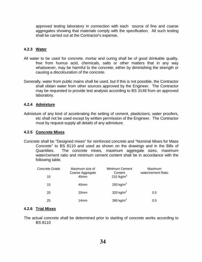
4.2.5 Concrete Mixes Concrete shall be "Designed mixes" for reinforced concrete and "Nominal Mixes for Mass
Concrete" to BS 8110 and used as shown on the drawings and in the Bills of Quantities. The concrete mixes, maximum aggregate sizes, maximum water/cement ratio and minimum cement content shall be in accordance with the following table.
Concrete Grade Maximum size of
Coarse Aggregate
Minimum Cement
Content
Maximum
water/cement Ratio
10
15
20
25
40mm
40mm
20mm
14mm
210 /kg/m3
250 kg/m3
320 kg/m3
390 kg/m3
0.5
0.5
4.2.6 Trial Mixes The actual concrete shall be determined prior to starting of concrete works according to
BS 8110
35
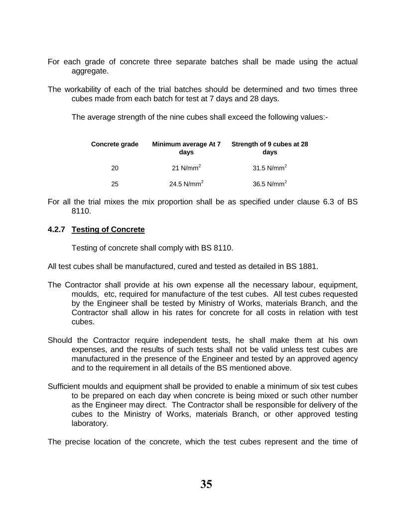
For each grade of concrete three separate batches shall be made using the actual
aggregate. The workability of each of the trial batches should be determined and two times three
cubes made from each batch for test at 7 days and 28 days. The average strength of the nine cubes shall exceed the following values:-
Concrete grade Minimum average At 7
days
Strength of 9 cubes at 28
days
20
25
21 N/mm2
24.5 N/mm2
31.5 N/mm2
36.5 N/mm2
For all the trial mixes the mix proportion shall be as specified under clause 6.3 of BS
8110. 4.2.7 Testing of Concrete Testing of concrete shall comply with BS 8110. All test cubes shall be manufactured, cured and tested as detailed in BS 1881. The Contractor shall provide at his own expense all the necessary labour, equipment,
moulds, etc, required for manufacture of the test cubes. All test cubes requested by the Engineer shall be tested by Ministry of Works, materials Branch, and the Contractor shall allow in his rates for concrete for all costs in relation with test cubes.
Should the Contractor require independent tests, he shall make them at his own
expenses, and the results of such tests shall not be valid unless test cubes are manufactured in the presence of the Engineer and tested by an approved agency and to the requirement in all details of the BS mentioned above.
Sufficient moulds and equipment shall be provided to enable a minimum of six test cubes
to be prepared on each day when concrete is being mixed or such other number as the Engineer may direct. The Contractor shall be responsible for delivery of the cubes to the Ministry of Works, materials Branch, or other approved testing laboratory.
The precise location of the concrete, which the test cubes represent and the time of
36
placing, shall be noted on the drawings or elsewhere. Where the concrete in the work is compacted by mechanical vibration, the test cubes
shall be compacted by mechanical vibration, and where the concrete in the work is compacted by hand, the test cubes shall also be compacted by hand as specified in BS 1881.
The Engineer may in the Laboratory make test cubes for any purpose from site materials,
and the Contractor shall supply such materials required free of charge. The test cubes shall be stored at the site of construction at a place free from vibration
under damp sacks for 24 hours after which time they shall be removed from their moulds, marked and buried in damp sand or under water until the time for delivery to the testing laboratory.
The cubes shall then be paced in damp sand or other suitable damp material and sent to
the testing laboratory, where they shall be similarly stored until the date of test. Test cubes shall be kept on the site for as long as practicable but for at least three-fourths of the period before testing, except for tests at ages less than seven days.
4.2.8 Standards for Acceptance of Cubes Tests The result of all cube tests shall be accepted by the Contractor and Engineer as true
results of the crushing strength of the cubes. The cube strength shall be calculated from the maximum load sustained by the cube at failure.
The appropriate strength required may be considered to be satisfied if the requirements in
BS 5328: Part 4, clause 3.16, are fulfilled. If the tests fail to give the required strength, further testing of the concrete shall be carried
out. If these tests fail to prove the strength of the concrete used, the Contractor shall at his own expense remove and replace all such concrete as directed by the Engineer.
4.2.9 Slump Tests Concrete consistency shall be determined by a slump test carried out in accordance with
BS 1881 and at the Contractor's expense. Unless otherwise specified by the Engineer, the following are the slump for the particular
class of work. Compaction by vibrator or Compaction by hand
37
Reinforced Concrete 30 to 60 mm Mass Concrete 0 to 30 mm, 30 to 80 mm Concrete having a slump test value exceeding the values here-in specified may be
rejected by the Engineer. 4.2.10Steel Reinforcement Steel for reinforced concrete shall be stored under cover clear of the ground and shall
comply with BS 4449, BS 4461 and BS 4483. All steel reinforcement shall be supplied by an approved manufacturer, and the
Contractor may be required to obtain a manufacturer's test certificate in respect of steel reinforcement supplied. In the absence of such a test certificate, the Contractor may be required to submit samples to be tested at the Contractors expense in such a manner as the Engineer may determine.
4.3 Precast Concrete Units Precast concrete shall be cast in properly made strong moulds true to the shapes
required. For work described "Finished Fair" the moulds shall be lined with hardboard, sheet metal or other approved material.
The concrete shall be thoroughly tamped in the moulds and shall not be removed from
them until 7 days after placing the concrete, but the sides may be removed after 3 days, provided the moulds are such that the sides are easily removable without damaging the concrete.
The precast work shall be cast under sheds and shall remain under same for 7 days in
the moulds and a further 7 after removal from the moulds. During the whole of the period, the concrete shall be shielded by sacking or other approved material kept wet. It shall then be removed from the sheds and stacked in the open for at least 7 days to season.
All precast work shall be cast in lengths convenient for handling unless otherwise
described. 4.4 Workmanship 4.4.1 Inspection of Reinforcement and Formwork No concreting shall commence until the reinforcement and formwork have been
38
inspected and approved by the Engineer. Reinforcement in walls and columns shall be inspected and approved before being enclosed in the formwork. Before concreting any part of the work, the Contractor shall give at least 24 hours notice in writing to the Engineer and obtain his approval.
The concrete shall be placed in layers as directed by the Engineer over the whole area to
be concreted and the second layer shall not be commenced until the first is completed. Sloping beds will not be allowed when placing concrete. Should any accidental segregation occur, the affected area shall be thoroughly turned over by hand until homogeneous mix has been obtained.
4.4.2 Mixing Concrete Concrete for grade 20 and grade 25 shall be mixed by weight batching only, unless
approval has been obtained from the Engineer for the concrete materials to be mixed by volume. Concrete for grade 10 and 15 can be mixed by volume.
The weight of coarse and fine aggregate in each batch shall be so computed that each
batch contains one or more full 50 Kg bags of cement. All concrete is to be mechanically mixed in a batch mixer of an approved type. The dry
materials for concrete shall be mixed in the mixer until a uniform colour is obtained after which the gauged quantity of water shall be gradually added. After all the water has been added, the mixer shall continue to mix for a period of not less than two minutes.
The mixers shall be equipped with an adjustable device capable of supplying a
predetermined amount of water. On the completion of each mixed batch of concrete, the mixer drum shall be completely
emptied before a fresh batch is placed therein. On the cessation of work, the mixer and all handling plant shall be washed out and shall always be left clean and free from hardened concrete.
Any mix considered to be unsatisfactory by the Engineer for any reason, will be
discharged to waste at the Contractor's expense, as and where directed by the Engineer, well clear of all mixed and placing operations in such a manner as to avoid the risk of defective concrete being incorporated in the works.
The mixer shall be maintained in a first class condition throughout the contract and any
mixer or plant, which is faulty in any respect, shall not be used. The drums of all mixers shall revolve at the speed recommended by the makers. A mixer which has been out of use for more than 20 minutes shall be thoroughly cleaned out
39
before ant fresh concrete is mixed. The Contractor shall always have one spare mixer ready on the site to avoid interruption
in the mixing and casting of concrete. 4.4.3 Transport and Placing of Concrete Concrete shall be transported in a manner which shall avoid a segragation of the
constituent material, and placing in the forms shall be completed before the concrete has taken its initial set. In no case shall concrete be placed dint he works more than 30 minutes after mixing. Concrete shall not be dropped through a height greater than 1.2m. Chutes may be used if they are constantly kept free from coatings or hardened concrete or other obstructions. Pumping of concrete through delivery pipes may be used, but only with the prior approval of the Engineer.
Concrete of any unit or section of the work shall be carried out in one continuous
operation, and no interruption of the concreting will be allowed without the approval of the Engineer.
The concrete shall be placed in layers as directed by the Engineer over the whole area to be concreted and the second layer shall not be commenced until the first is completed. Sloping beds will not be allowed when placing concrete. Should any accidental segregation occur, the affected area shall be thoroughly turned over by hand until a homogeneous mix has been obtained.
When concreting walls and columns, the mix proportions of the first 250mm depth of
concrete placed in contact with the horizontal joint should be adjusted by reducing the amount of coarse aggregate.
4.4.4 Compaction After the concrete has been placed in a position it shall be compacted by vibration with a
rigid poker type with internal vibrator approved by the Engineer. The Concrete shall be worked well up against the form, joints and around the reinforcement and be free from voids and other imperfections. Under no circumstances shall the concrete be shifted or transported inside the form with vibrator.
The Contractor shall always have one spare vibrator ready on the site to avoid
interruption in the mixing, casting and vibrating of concrete. In the case of reinforced concrete, a competent steel fixer shall be in constant attendance
during the placing of concrete to adjust and correct the position of the
40
reinforcement, if so required, immediately before the concrete is placed. In no case shall the vibrators be attached to or be allowed to come into contact with the reinforcement.
Each freshly placed layer of concrete must be thoroughly compacted and worked into the
preceding one but care shall be taken that no damage is done to previous work that has already set. Excessive compaction of concrete shall be avoided.
The upper surface of slabs shall be compacted by approved external vibrator. 4.4.5 Placing of Concrete under Water Concrete shall only be placed under water with the prior approval of the Engineer who
shall likewise approve the methods to be used and the precautions necessary to prevent loss of material. In no circumstances shall concrete be dropped or placed in water in a loose condition or be placed in flowing water. In all cases the cement content shall be increased by 25% for each class of concrete at the Contractors' Expense.
4.4.6 Placing of Concrete on Earth Surface Earth surfaces on which concrete is to be placed shall be clean, firm and free from
standing or flowing water. After the excavation has been completed to the approved lines, levels and dimensions it shall be kept as damp as practicable to reduce absorption of water from the concrete to a minimum. No concrete shall be placed until the prepared earth surface has been approved by the Engineer.
4.4.7 Construction and Expansion Joints The position and arrangement of construction and expansion joints shall be as shown on
the drawings. Where additional joints are requested, the positions must be approved by the Engineer.
All construction joints shall be rebated to form a key with subsequent work. Concreting of
any unit or section of the work shall be carried out in one continuous operation up to construction joints and no interruption of the concreting will be allowed without approval.
Where shown on the drawings, construction and expansion joints shall be provided with
water bars of P.V.C or other approved material. The widths and shapes of the water bars shall be as specified on the drawings and all joints shall be used. The trade mark of the water bars shall be approved by the Engineer before commencement of work, and fixing and jointing of water bars shall be approved by
41
the Engineer before commencement of work, and fixing and jointing of water bars shall be approved by the Engineer before costing.
The fusing of water bars shall be performed in a way so as to secure that the two bars are
joined over the entire width. The fused joint shall be able to withstand tension and shall be intact after 10 consecutive bendings. The Engineer may request that the fusing is carried out by specialists.
Where shown on the drawings, joints shall be provided with a joint sealing compound.
The sealing compound shall be a two component polysulphide rubber sealing compound complying with BS 4254, and the trade mark shall be approved by the Engineer. The compound shall be placed in a chase made by a fillet strip in the formwork. The concrete shall be dry and a suitable primer shall be applied to the joint before applying the sealant. The procedure for the workmanship shall be approved by the Engineer before commencement of work, but the Contractor shall have the full responsibility for the watertightness of the joints.
It should be noted that the lower part of the concrete walls shall be cast together with the
floor slab and no joint directly on the slab will be permitted. Before depositing fresh concrete against which the already set, the face of the latter shall
be roughened to expose the coarse aggregate, all cement latency removed whilst the concrete is still green and the surface thoroughly wetted with water and cleared of foreign matter. Cement mortar grout mixed in the proportion of one partof cement to two parts of sand shall be spread to a thickness of 5mm over the face of the set concrete before fresh concrete is deposited.
4.4.8 Curing and protection of Concrete Curing shall be as soon as the surface of the concrete has hardened sufficiently. All
exposed concrete surfaces shall be cured for a period of seven days by covering them with a layer of sand, hessian canvas or other approved material kept damp. Concrete shall be protected from sun, wind, heavy rains and flowing water for at least three days after placing.
4.4.9 Finishes of Horizontal Surfaces Concrete surfaces for floor shall be true to level and falls as shown on the drawings.
Water coming to the surface when vibrating shall be removed. After casting the surface shall be smoothened with a wooden flat. After some hours, when the surface has dried up, the surface shall be towelled smooth with a steel trowel.
All other horizontal surfaces shall have the same surface finish except for the final
42
towelling with steel trowel. 4.4.10 Finishes of Vertical Surfaces The shuttering for exposed concrete faces shall be so constructed that the latter shall be
true to line and surface. The concrete shall be consolidated as specified against the shuttering to keep the face of the work free from honeycombing and other blemishes.
After removal of the shuttering, no concrete surfaces shall be treated in any way until they
have been inspected by the Engineer. If upon removal of the shuttering, the line of surface of the work is, in the opinion of the
Engineer, unsightly and not in accordance with the requirements of the contract, the Contractor shall at his own expense cut out and make good such portions of the work as the Engineer directs.
Rendering over defective surfaces shall not be permitted. Areas of honeycombing shall
with the approval of the Engineer be made good immediately upon removal of the shuttering, and isolated superficial air and water holes shall be filled. Care shall be taken not to leave mortar or cement on parts of the surface which have been cast smooth and without pores.
Unless otherwise instructed, the face of exposed concrete placed against shuttering shall
after removal of the shuttering be rubbed down woth a carborundum stone or in other approved manner to remove fins and other irregularities, and washed perfectly clean.
Concealed concrete faces shall be left as from the shuttering, except that surfaces with
honeycombing shall be made good. 4.4.11 Accuracy of Finish The arrangement of all formwork shall be made in such a way that all dimensions shall
comply as exactly as possible with those given on the drawings. The following tolerance shall be respected.
Foundations = 50 mm Position of columns and Walls = 5 mm Thickness of walls = 5 mm Lateral dimensions of columns = 5 mm Level of slabs, beams = 5 mm Slab thickness = 5 mm Lateral dimensions of beams = 5 mm
43
Plumb of columns and walls = 3 mm in each storey (non/accumulative) Window and door opening sizes = 5 mm Surfaces and edges must not show any noticeable wrapping. On a length of less than
10m the deviation may be 10mm at the most. The Contractor shall be responsible for the cost of all corrective measures required by the
Engineer to rectify work which is not constructed within the tolerance set out above.
4.4.12Construction of Formwork All formwork shall be substantially and rigidly constructed of timber or steel or pre-cast
concrete or other approved materials and shall be true to the shape, line, level and dimensions shown on the drawings.
Timber shall be well seasoned, free from loose knots and or forkworm of exposed
concrete faces be planned to thickness. Faces in contact with concrete shall be free from adhering grout, projecting nails, splits, or other defects that will mark the concrete surface. Formwork for foundations and other concealed work may be undresses or rough timber.
All joints shall be sufficiently tight to prevent leakage of cement grout and to avoid the
formation of fins or other blemishes, and all faulty joints shall be caulked. All formwork shall be thoroughly cleaned and coated with an approved type of oil before
it is fixed in position. Immediately before concreting the formwork shall be watered thoroughly and washed out to remove sawdust, shavings, or other rubbish. Where the appearance of the concrete face is important, the position and direction of the joints shall be as directed.
Filet strips shall be fixed in the formwork to form a chamber 20mm by 20mm on all
external corners of the concrete. Openings for inspection of the inside of the formwork for walls, beams and similar work
and for the escape of wash water shall be formed in such a way that they can be conveniently closed before starting to place the concrete.
Connections between formwork elements shall be constructed to allow for easy removal
of the formwork, and shall be either nailed, screwed, bolted, clamped, braced or otherwise fixed securing a sufficient strength to retain the correct shape and line during compaction of the concrete.

44
Bracing members placed in the formwork to keep two sides of formwork in exact position shall be approved by the Engineer. Holes in the concrete after bracing arrangement shall be made good by plugging with approved material.
Top formwork shall be provided to concrete faces where the slope exceeds 1 vertical to
21/2 horizontal. Such formwork shall be counterweighed or otherwise anchored floating.
The formwork shall be so designed that the formwork for soffits of slabs and for sides of
beams, columns and walls may be removed first leaving the formwork for the soffits of beams and their supports in position. Wedging or other suitable ways of adjustment shall be provided to allow accurate adjustments of the formwork and to allow a gradual removal of the same without jarring the concrete.
On demand the Contractor shall provide such drawings and calculations as necessary for
determination of the structural strength of the formwork. The Engineer's approval of such drawings and calculations will not relieve the Contractor of his responsibilities under the contract.
Formwork shall be erected true to line and braced and shutted to prevent deformation
under the weight and pressure of the wet concrete, construction loads, wind pressure or other forces. Forming for beam soffits shall be erected with an upward camber as shown on the drawings or as directed by the Engineer or of 2mm for each 1m of horizontal span.
Re-proping of beams will not be approved except when props are re-instated to relieve
the beams of loads in excess of the design load. Vertical; props shall be supported on folding wedges on sole-plates, or other measures shall be taken whereby the props can be gently lowered vertically when commencing to remove the formwork.
If, in the opinion of the Engineer, the formwork is faulty, inadequate or does not comply
with the specifications, then the Contractor shall at his own cost modify the formwork until it meets the approval of the Engineer.
4.4.13 Mould Oil All faces of formwork that will come in contact with wet concrete shall be treated with
approved mould oil or other coating to prevent adherence to the concrete. Such coatings shall be insoluble in water, non-staining, nor injurious to the concrete,
45
shall not become flaky and shall not be removable by rain or wash-water. Liquids that retard the setting of cement shall only be applied to the shuttering when approved. Mould oils and similar coatings shall be kept free from contact with the reinforcement.
4.4.14 Holes for Pipes, Cast-in Items etc., General The Contractor shall be responsible for the co-ordination with the sub-contractors for the
setting out and fixing of all pipes and holes, pockets and chases for pipes. Sleeves provided by the sub-contractors are to be accurately set out and cast in and cutting away in completed concrete work is to be minimized.
Details of all holes etc. required in a structural work for services must be submitted to the
Engineer who will assess the necessity for extra trimming reinforcement. No opening, holes, chases, etc, are to be formed in the concrete without the approval of
the Engineer and details of fixtures or fixings to be cast in must be approved. 4.4.15 Pipes through Water Retaining Walls Pipes passing through water retaining walls and floors shall, wherever possible, be built
into the stricture in-situ. Shuttering shall be formed closely to the outside of the pipe, and concrete shall be placed and compacted thoroughly round the pipe.
Pipes, bolts and other steel items cast into the concrete in water retaining structures must
not in any way be in contact with the steel reinforcement. When not possible to build in place, pipes shall pass through preformed holes. Holes
shall be formed with formwrok which shall be stripped cleanly and without shock to the concrete. As soon as the shuttering is tripped, the hole shall be thoroughly wire brushed to expose the aggregate. The hole shall be as neat as possible to allow the pipe to be passed through the wall, while the corners shall be chamfered or rounded.
The pipe shall be set and the hole filled up as soon as possible. Immediately before
filling, the hole shall be continuously soaked so as to saturate the concrete, and the surface coated with a stiff mix of 1:1 sand grout. Shutters shall be fixed true to the faces of the wall, and stiff mix of concrete packed in until the hold is completely filled, particulat care to be taken to ensure that the spaces beneath the invert of the pipes and beneath the slopping soffit of the hole are completely filled. Shuttering shall be stripped as soon as possible and filling rubbed smooth. The filling and the surrounding concrete shall be kept wet for 7 days after filling.
46
4.4.16 Removal of Formwork Formwork shall be left in position until the concrete has attained sufficient strength to be
self-supporting. The Contractor shall be responsible for the safe removal of the formwork without shock or vibration - which would damage the concrete.
Any work showing sign of damage through premature removal of formwork or through
premature loading shall be entirely reconstructed at the contractor's expense. The Engineer may delay the time of removal of formwork if necessary. Subject to the above, the minimum period for removal of formwork shall generally be as follows:-
Slabs Soffits (props left under) 7 days Props 21 days Beams Sides 3 days Soffits 21 days Walls and Columns (unloaded) 3 days When formwork is removed after 3 days, it will be necessary to ensure that the exposed
surfaces of the concrete are kept thoroughly wet for the period of curing. 4.4.17 Reinforcement All bending, cutting and fixing to comply with BS 8110 and BS 4466. Normally bending
schedules are incorporated into the Contract Drawings, but the Contractor shall satisfy himself about their accuracy and about their complete coverage of the work involved. Any omission, inaccuracy or other errors observed by the Contractor shall be reported to the Engineer before commencement of the work.
In case of errors in bending schedules, no extra payment will be approved, provided the
reinforcement is shown correctly on the contract drawings. Bars shall be of the shown lengths, and lapping, except where indicated on the drawings,
is not permitted unless approved by the Engineer. Spacing between bars shall not differ more than 5mm from the required spacing. Any
inaccuracy in the total length of a bar as cut shall be compensated for in the end hooks or other approved parts of the bar.
The internal radius of a bend shall neither be less than allowed by BS 4466 nor less than
the radius given in the Bending Schedule. The steel reinforcement shall be assembled and fixed in the form of a rigid case. To prevent displacement before or during concreting the bars shall be secured one to the other with approved binding wire at each intersection. In slabs and walls binding at every second
47
intersection is sufficient. Concrete cover blocks (mix 1:3) shall unless otherwise directed be used between the
reinforcement, the bottoms and sides of the forms to ensure the specified concrete cover to the bars. Variations of cover shall be kept within plus/minus 3mm from the specified cover.
The minimum clear horizontal distance between adjacent bars shall be of 25mm or the
diameter of the bar whichever is the biggest, and 25mm vertically. Space bars shall be inserted at such intervals that the bars do not perceptibly sag. Projecting bars shall be adequately protected against displacement both during and after concreting.
At the time of fixing and when concrete is being placed, all reinforcement shall be free
from oil, painting, grease, dust and scale or any other coating which would destroy and bond with the concrete. The Contractor must obtain the Engineer's approval of the reinforcement when places, before any concreting is commenced.
48
5.0 MASONRY WORKS 5.1 Concrete Block walling 5.1.1 Precast Concrete Blocks Concrete Blocks shall comply with BS 6073. The blocks shall be solid or hollow as
specified on the drawings, with a minimum comprehensive strength of 3.5 N/mm2, tested as described in BS 6073.
All blocks must be left with goods sharp edges. The standard face size of blocks for use
in the works shall be 440mm x 190mmx190mm and this size of blocks shall be used whenever practicable.
The Contractor shall be responsible for making test blocks and experimenting with
available materials to ascertain what mix will be necessary to attain the required strength. If suitable materials are not available locally, the Contractor shall obtain them from other approved sources.
Manufacture shall be carried out under shelter and after casting, the blocks shall be
struck under shelter to protect them from sun and weather, and properly cured by covering with sand or sacks and sprayed daily for not less than 14 days.
5.1.2 Wall reinforcement Reinforcement in walls made of solid blocks shall where so specified consist of a 25mm
wide strip of "Exmet" or similar block reinforcement centrally in joints at a approximately 450mm centre (vertically) for the fullness of the walls, lapped and crumped 300mm at running joints and full width of walls at angles and intersections.
5.1.3 Sand The sand for mortar shall be fine sand. 5.1.4 Mortar The cement mortar shall consist of 1 part of Portland cement to 4 parts of sand by volume
or as specified on the drawing. 5.1.5 Damp-Proof Coarse
49
All Damp-proof coarse shall be of bituminous felt to BS 743 weighing not less than 3 Kg/m2 free from tears and holes, lapped 150mm at running joint and for full width of wall at angles and intersection and bended and including at 12mm leveled screed of cement mortar.
5.1.6 Workmanship Blocks shall be laid in regular even courses and shall be bedded in cement mortar
consisting of 1 part of cement to 3 parts of sand or as indicated on the drawing. All bends and vertical joints shall be filled completely with mortar when the blocks are laid. All exposed faces of wall for plastering are to be left rough and the joints raked out while
mortar is green to form adequate key. All other faces shall be cleaned down on completion with wire brush or as necessary and
mortar dropping, smear marks, etc removed. Where block work faces are to be left exposed, blocks shall be chosen for their uniformity,
and unmarked faces and unbroken arises and shall be finished with a fair face and pointed with a neat joint recessed from the face pf the blocks.
5.1.7 Block work Tanks The concrete blocks shall be solid, type A with a minimum comprehensive strength of
7N/mm2, tested as described in BS 2028 for circular block work tanks, the blocks shall be manufactured as the required shape to fit the curvature of the tank, and all block shall be immersed in water for 24 hrs before being laid.
Internal plaster shall be of mix 1:2, made water proof by use of approved additive. 5.2 Plaster Work 5.2.1 Lime The lime for plastering shall comply with BS 890 clause "A" for non-hydraulic lime and
shall be as obtainable and to approved.
50
5.2.2 Composition of Plaster A mix referred as 1:4 or other mixes as specified on the drawing shall be used. 5.2.3Surfaces All surfaces to be paved or plastered must be brushed clean and well wetted before each
coat is applied. All cement pavings and plaster shall be kept continuously damp in the interval between application of coats and for seven days after the application of the final coat.
5.2.4Partially or wholly set materials Partially or wholly set materials will not be allowed to be used or remixed. the plaster
mixes etc. must be used within one hour of being combined with water. 5.2.5Samples The contractor shall prepare sample areas of the screed, pavings and plastering as
directed until the quality, texture and finish required is obtained and approved by the Engineer, after which all work executed shall conform with the respective approved samples.
5.2.6Finish Generally All screed and pavings shall be finished smooth, even and truly level unless otherwise
specified. Rendering and plastering shall be finished plumb, square, smooth and even. All surfaces to be plastered shall be thoroughly wetted before any plastering is
commenced. No plastering will be allowed to take place until all chases for services have been cut,
services installed and chased made good. On no account may finished plaster surface be chased and made good. All work shall be to the approval of the Engineer and any work not complying with the
above shall be hacked away and replaced at the Contractor's expense.
51
5.2.7Arises and Angles All arises and angles shall be clean and sharp or slightly rounded or thumb-covered as
directed including neatly forming mitres. 5.2.8Making Good All making good shall be cut out to a rectangular shape, the edges undercut to form
dovetail key and finished flush with the face of surrounding paving or plaster. All cracks, blisters and other defects shall be cut out and made good and the whole of the works shall be perfect on completion.
5.2.9Cement Pavings, Screed etc. Cement screed shall consist of cement and sand mix 1:2 laid in panels and finished with
a steel trowel if not otherwise specified. Where specified as waterproof "pudlo" or similar waterproofing compound shall be added
to the cement paving or screed strictly in accordance with the manufacturer's instructions.
Where practicable, screed is to be laid while the concrete is still green. When this is not
practicable, the concrete is to be well washed and brushed perfectly clean with a steel wire brush, to remove laitance and to give a roughened face as a key and then kept wet for at least seven days before the screed is laid. On the day of laying the surface is to be only damp with all surplus water removed and has to be painted with cement and sand mix 1:1 grout immediately before commencing laying of the screed. The grout is to be applied continuously in front of the screed, and not in large areas that will dry out before the screed is applied.
Screed shall be protected during the first stage of hardening from harmful effects of sunshine, drying winds, rain or water. In exposed positions, the screed shall be covered with a well wetted layer of sawdust, hessian or other approved material, and this layer shall be damp for at least seven days, during which period no traffic is to be allowed over the screed.
5.2.10 Cement Rending Cement rending shall consist of cement and sand mix 1:4 to not less than 15mm finished
thickness and be furnished to a true and even surface.
52
5.3Carpentry and Joinery 5.3.1 Timber Materials All timber shall be in accordance with the latest approved grading rules issued by the
Government of Kenya or other competent authority (legal notice No. 358). The quality shall be as first (or prime) grade. All timber works to be carried out in
accordance with BS 1186 and CP 112. Any of the following timber may be used: Standard Common Name Botanical Name Podocarpus Podocarpus Spp CedarJuniperus Procera African Mahogany(Munyama)Khaya anthotheca MiningaPterocarpus Angloensis MvuleChrophora Excelsa All timber shall be free of live borer beetle or other insect atteck when brought upon the
site. The contractor shall be responsible upto the end of the maintenance period for executing at his own cost all work necessary to eradicate insect atteck of timber which becomes evident-including the replacement of timber attacked or suspected of being attacked, notwithstanding that the timber concerned may have already been inspected and passed as fit for use.
All timber shall be seasoned to a moisture content of not more than 15%. 5.3.2Boards and Sheets Fibreboard Shall be 12mm "Celotex" or other approved fibreboard complying with BS
1142, Part 3 Plywood Shall be laminated board faced on in both sides with 4mm plywood. Exposed
edges shall be lipped with 20mm hardwood and rates shall include for leaping.
Plastic Sheeting Shall be 45mm thick, and shall be obtained from an approved
manufacturer. The doors shall comply with BS 459, Part 2. External doors shall be framed, ledged and braced as shown on the drawings, and they shall comply with BS 459, Part 4.
53
5.3.3Workmanship All timber shall be as long as possible and practicable to eliminate joints. Where joints
are unavoidable, surfaces shall be in contact over the whole area of the joint before fastenings are applied.
No nails, screws or bolts are to be fixed in any split end. If splitting is likely, or is
encountered in the course of the work, holes for nails must be bent at right angles to the grain.
All exposed surfaces of joinery work shall be wrought and all arises "eased off" by
planning and sand papering to an approved finish suitable to the specified treatment.
Where intended to be in contact with stone, concrete blocks, cement or plaster, the backs
and other faces of all doors, windows and other frames and linings, posts, architectural skirting, fillets and fascias shall be treated with two coats of wood preservative before fixing.
Bottom edges of doors shall be painted with one coat of approved primer before fixing. Any fixed joinery which in the opinion of the Engineer is liable to become bruised or
damaged in any way shall be completely cased and protected by the contractor until the completion of the works.
5.3.4Inspection and Testing The Engineer shall be given facilities for inspection of all works in progress whether in
workshop or on site. Such tests will be carried out by the Forestry Department. 5.3.5Clearing Up The contractor is to clear out and destroy or remove all cut ends, shavings and other
wood waste from all parts of the building and the site as the work progresses and at the conclusion of the work.
This is to prevent accidental borer infestation and to discourage termites and decay. 5.4Roofing 5.4.1Asbestos Roof Sheeting The floor sheeting and fittings shall be "Super-Seven" corrugated asbestos cement

54
roofing, manufactured by the Kenya Asbestos Cement Company Limited laid and fixed in strict accordance with the manufacturers instructions.
Fixing to be of approved type and quality. 5.4.2Protection All roof surfaces shall be kept clean and protected and handed over watertight at
completion. 5.5Steelwork 5.5.1Materials All materials shall be the best of their respective kinds and free from defects. The
materials in all stages of transportation handling and stacking shall be kept clean and injury from breaking, bending and distortion prevented.
All steel and steel sections shall comply with BS 4, BS 4360 and BS 4848. All steel shall be of approved manufacture and the contractor shall on request deliver to
the Engineer a manufacturers test certificate for all steel used. All structural steel shall be of grade 43A according to BS 4360. Steel for handrails, screens etc. can be of lower grade, but all steel shall be weldable and
the grade shall be approved by the Engineer. Electrodes shall be of a class appropriate to the steel. Bolts and nuts shall be according
to BS 4190. 5.5.2Workmanship Workmanship for all steelwork shall generally follow the requirements in BS 449 and BS
5135. The contractor shall prepare all the necessary workshop drawings, which shall be
approved by the Engineer. The Engineer's approval shall not in any way relieve the contractor of his responsibility for the workshop drawings being in accordance with the contract drawings and specifications.
All welding of structural steel shall be carried out in the contractors workshop and the
whole structure or pars thereof shall be test assembled in the workshop before
55
delivery to the site. Should any doubt arise as to the quality of the steel or the welds, the Engineer may
require testing carried out. If the results show insufficient quality of materials or workmanship, the contractor shall cover all expenses related to the tests and shall replace and rectify all materials and welds found unsatisfactory.
5.5.3 Ladders Ladders and tanks etc shall be galvanized steel pipes in accordance with BS 1387
"Medium clause" and shall be made to the dimensions on the drawing. 5.6Ironmongery and other Fittings All ironmongery shall be approved by the Engineer. The approved samples shall be
regarded as the standard for work. 5.6.1Locks All locks and ironmongery shall be with screws, etc. to match. Before the door etc. is
painted, handles shall be removed, carefully stored and refixed after completion of painting. Locks shall be oiled and left in perfect working order.
25mm diameter rubber door stops shall be provided at all doors and securely plugged
and screwed to floors or walls. All external doors shall be provided with locks of cylinder type. All internal doors to be
provided with approved latch locks and handles. All locks shall have two keys with attached labels with door references before being handed over to the Engineer.
5.6.2Sanitary Fittings All sanitary fittings shall be of approved manufacture and installed in accordance with the
manufacturer's recommendation. 5.7 Glazing 5.7.1Glass All glass shall comply with BS 952 and be free from flaws, bubbles, specks and other
imperfections. Glass panes shall be cut to sizes to fit the opening with not more than 2mm play all round
and where puttied shall be clipped to the frames.
56
Clear sheet glass shall be of ordinary glazing quality 5.7.2Cleaning Etc On completion, remove all broken, scratched or cracked panes and replace with new to
the satisfaction of the Engineer. Clean inside and out with approved liquid cleaner. On no account shall windows be cleaned by scrapping with glass.
5.8Painting, Decorating and other surface Treatment 5.8.1Approved Specialist An approved specialist must execute all work under this trade unless the Engineer agrees
otherwise. The paint shall be of approved manufacture. 5.8.2General The contractor shall so arrange his programme of work that all other trades are
completed and the workmen are away from the area to be painted, when painting begins. Before painting, the contractor must remove all concrete and mortar dropping and the like from all work to be decorated and remove all stains as to obtain uniform colour to work to be oiled and polished.
All plaster, metal, wood and other surfaces which are to receive finishes of paint, stain,
and distemper or paint work of any description are to be carefully inspected by the contractor before he allows any of his painters to commence work.
5.8.3Painting Generally All materials to be applied externally shall be of exterior quality and/or recommended by
the manufacturers for external use, all in accordance with BS 4800 or similar. All materials shall be delivered on site intact in the original sealed drums of tins and shall
be mixed and applied strictly in accordance with the manufacturer's instruction and to the approval of the Engineer.
Unless specially instructed or approved by the Engineer, no paints are to be thinned or
otherwise adulterated, but are to be used as supplied by the manufacturers and direct from the tins.
The priming, undercoats and finishing coats shall each be of differing tints and the
priming and undercoats shall be the correct brands and tints to suit the respective
57
finishing coats in accordance with the manufacturer's instruction. No painting is to be done in wet weather or on surfaces which are not thoroughly dry. Each coat shall be properly dry and in the case of oil or enamel paints shall be well
rubbed down with fine glass paper before the next coat is applied. The paint work shall be finished smooth and free from brush marks.
5.8.4Preparation and priming of plaster etc. surfaces Surfaces shall be perfectly smooth, free from defects and ready for decoration. All such
surfaces shall be allowed to dry for a minimum period of six weeks, stopped with approved plaster compound stopping and rubbed down flush, as necessary, and then be thoroughly brushed down and left free from all efflorescence, dirt and dust immediately prior to decorating.
Plaster surfaces, which are to be finished with emulsion, oil or enamel paint, shall be
primed with an alkali resisting primer complying with the particular paint manufacturer's specification and applied in accordance with their instructions.
Fibreboard or similar surfaces shall be lightly brushed down to remove all dirt, dust and
loose particles and have all nail holes or other defects stopped with an approved plaster compound stopping rubbed down flush and left with a texture to match surrounding material.
5.8.5Preparation and Priming of Metalwork All surfaces shall be thoroughly brushed down with wire brushes and scraped were
necessary to remove all scale, ruast, etc. immediately prior to decorating. Where severe rust exists and if approved by the Engineer, a proprietary de-rusting solution may be used in accordance with the manufacturer's instructions.
Shop primed and unprimed surfaces shall be given one coat of metal chromate primer or
lead oxide primer. Galvanized surfaces shall be treated before priming with an approved proprietary mordant
or de-greasing solution. The surfaces shall be thoroughly washed down with water, allowed to dry and primed at last.
Coated surfaces already treated with bituminous solution, shall be scraped to remove soft
parts and then receive two isolating coats of aluminium primer or other approved ant-tar primer.
5.8.6Preparation and Priming Woodwork
58
All woodwork shall be rubbed down, all knots, covered with a thick coat of good shellac or
aluminium knotting; primed with one coat of approved ready-mixed proprietary wood primer and all cracks, nail holes, defects and uneven surfaces, etc. , stopped and faced up with hard stopping rubbed down flush.
5.8.7Wood Preservative All woodwork in contact with walling or plaster shall be treated after cutting and
preparation but before assembly or fixing with one coat of approved wood preservative. The solution is to be brushed on all faces of all timbers, unless exposed to view and painted.
5.8.8Cement Paint Shall be super snowcem or equal and approved. Two coats shall be applied after
preparation as specified above. 5.8.9Emulsion Paint After preparation as specified above, a minimum of three coats shall be applied using a
thinning medium or water only if and recommended by the manufacturer. An approved plaster primer tinted to match may be substituted for the first coat. 5.8.10Enamel Paint Apply two undercoats and one finishing coat, after preparation and priming as
specified above. 5.8.11Lining of Chemical Tanks The lining of chemical tanks with "EPOBOND" and "EPOFLOOR" shall be carried out by
specialists approved for such work by the manufacturer or his agent 5.8.12Cover Up Cover all floors, fittings, etc. with dust sheets when executing all painting and decoration
work. 5.8.13Clean and Touch Up

59
Paint splashes, spots and stains shall be removed from floors, woodwork, etc., any
damaged surfaces touched up and the whole of the work left clean and perfect upon completion and during the maintenance period.
60
6 PIPE WORKS
6.1Materials 6.1.1Concrete Pipes General Precast concrete pipes and fittings shall comply with BS 5911: Part 100. Minimum crushing test loads shall be as specified in Table 7 of the said standard. Where plot chambers are connected directly to the main sewer, the connection shall be
done by oblique-angled junctions with an angle of 450 Concrete pipes with flexible joints The joints of pipes and junction shall be of a type which is able to maintain a maximum
angular and straight movement as shown in the following table, without loss of water tightness under the pressure stated in clause 7.7 Testing.
Internal Diameter 150 225 300 375 450 525
Angular movement 1.670 1.190 0.890 0.720 0.60 0.50.4
Concrete pipes with rigid joints The joints of pipes and junctions shall be sealed with mortar mix 1:3. 6.1.2Unplasticised Polyvnyl chloride (UPVC) Pipes All UPVC pipes and fittings shall comply with ISO-standard 4435 or BS 4660:1973/78 and
BS 5481:1977. Nominal outside diameter and nominal wall thickness of the PVC pipes are shown in the
following table: -
Nominal Outside diameter in mm
160 200 250 315
Class 41 Nominal wall thickness in mm
3.9 4.9 6.1 7.7
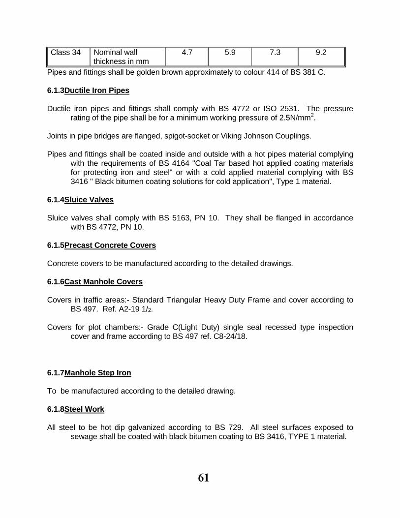
61
Class 34 Nominal wall thickness in mm
4.7 5.9 7.3 9.2
Pipes and fittings shall be golden brown approximately to colour 414 of BS 381 C. 6.1.3Ductile Iron Pipes Ductile iron pipes and fittings shall comply with BS 4772 or ISO 2531. The pressure
rating of the pipe shall be for a minimum working pressure of 2.5N/mm2. Joints in pipe bridges are flanged, spigot-socket or Viking Johnson Couplings. Pipes and fittings shall be coated inside and outside with a hot pipes material complying
with the requirements of BS 4164 "Coal Tar based hot applied coating materials for protecting iron and steel" or with a cold applied material complying with BS 3416 " Black bitumen coating solutions for cold application", Type 1 material.
6.1.4Sluice Valves Sluice valves shall comply with BS 5163, PN 10. They shall be flanged in accordance
with BS 4772, PN 10. 6.1.5Precast Concrete Covers Concrete covers to be manufactured according to the detailed drawings. 6.1.6Cast Manhole Covers Covers in traffic areas:- Standard Triangular Heavy Duty Frame and cover according to
BS 497. Ref. A2-19 1/2. Covers for plot chambers:- Grade C(Light Duty) single seal recessed type inspection
cover and frame according to BS 497 ref. C8-24/18. 6.1.7Manhole Step Iron To be manufactured according to the detailed drawing. 6.1.8Steel Work All steel to be hot dip galvanized according to BS 729. All steel surfaces exposed to
sewage shall be coated with black bitumen coating to BS 3416, TYPE 1 material.
62
6.2Handling and Storing Materials 6.2.1General The method of transportation, handling and storing of pipes and fittings shall be in
accordance with the manufacturer's recommendations. Pipes, valves, specials and other materials shall be handled, moved, lifted or lowered with
the least possible impact. Handling equipment shall be of approved type. In slinging pipes, only flat slings shall be used and the use of chain slings, hooks or other devices working on scissors or grab principles shall not be permitted. Pipes shall be slung from two or more points as the Engineer may direct and the slinging, lifting and lowering shall be in the hands of a competent and experienced man. Care shall be taken to keep pipes and fittings clean and free from soil, mud, dirty water, solvents chemicals etc.
Subject to the requirements of inspection before acceptance, protective bolsters, caps or
discs on the ends of flanges of pipes or specials shall not be removed until the pipes or specials are about to be lowered into the trench. Every precaution shall be taken to prevent damage to internal linings of external coatings.
Pipes in storage shall be supported clear of the ground on approved supports and
adequately braced to prevent rolling. They shall not be stacked more than four tiers high without the approval of the Engineer.
Materials of different classification shall be stored separately. All pipes and associated material shass at all times be protected from sun and wether to
the satisfaction of the Engineer. No valves shall be lifted by the spindle. No valves, fittings or specials shall be stacked more than one tier high without the
permission of the Engineer, and they shall not be stored in a dirty place or condition and shall not be allowed to become embedded in earth, sand, stone, aggregate, water, fuel, or any other deleterious matter.
Valves and their ancillary equipment shall be protected before and after erection against
collapse of earthworks, falls of materials, concrete and cement droppings, wood and other matter.
Shortly before the laying or fixing any valve, pipe or fitting the contractor shall in the
presence of the Engineer or his representative carefully examine each valve, pipe
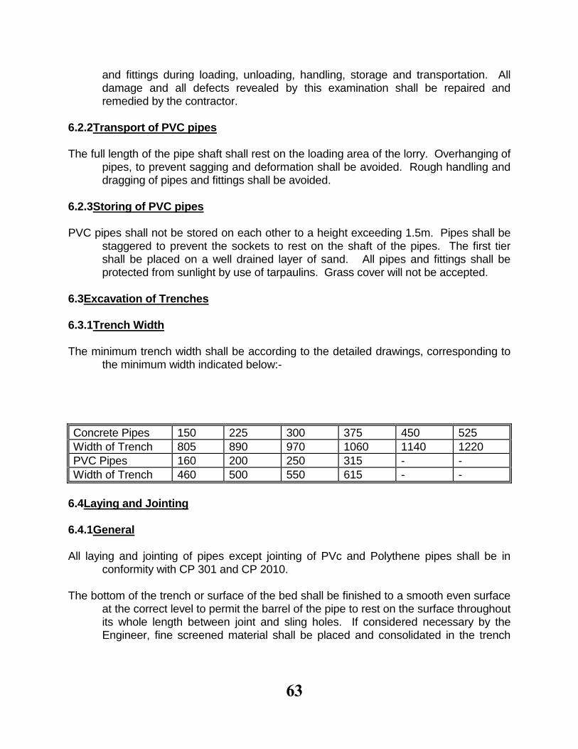
63
and fittings during loading, unloading, handling, storage and transportation. All damage and all defects revealed by this examination shall be repaired and remedied by the contractor.
6.2.2Transport of PVC pipes The full length of the pipe shaft shall rest on the loading area of the lorry. Overhanging of
pipes, to prevent sagging and deformation shall be avoided. Rough handling and dragging of pipes and fittings shall be avoided.
6.2.3Storing of PVC pipes PVC pipes shall not be stored on each other to a height exceeding 1.5m. Pipes shall be
staggered to prevent the sockets to rest on the shaft of the pipes. The first tier shall be placed on a well drained layer of sand. All pipes and fittings shall be protected from sunlight by use of tarpaulins. Grass cover will not be accepted.
6.3Excavation of Trenches 6.3.1Trench Width The minimum trench width shall be according to the detailed drawings, corresponding to
the minimum width indicated below:-
Concrete Pipes 150 225 300 375 450 525
Width of Trench 805 890 970 1060 1140 1220
PVC Pipes 160 200 250 315 - -
Width of Trench 460 500 550 615 - -
6.4Laying and Jointing 6.4.1General All laying and jointing of pipes except jointing of PVc and Polythene pipes shall be in
conformity with CP 301 and CP 2010. The bottom of the trench or surface of the bed shall be finished to a smooth even surface
at the correct level to permit the barrel of the pipe to rest on the surface throughout its whole length between joint and sling holes. If considered necessary by the Engineer, fine screened material shall be placed and consolidated in the trench

64
bottom to provide such a bed. The bottom of the trench and pipe bed shall be inspected by the Engineer, and only when passed as satisfactory shall pipe laying commence.
Each pipe shall be laid accurately to line, level and gradient sothat, except where
otherwise directed, the finished pipe line shall be in a straight line both in horizontal and vertical plans.
The levels and gradients shown on the drawing shall be rigidly adhered to unless
otherwise ordered by the Engineer. Where lines of pipe are to be constructed, the contractor shall provide and fix, at such
points as may be directed, properly painted and securely positioned sight rails, the levels and positions of which shall be examined and checked by the Engineer before the rails are used and as often thereafter as may be necessary.
There shall at no time be less than three sight rails in position on each length of pipeline
under construction to any one gradient, and the sight rails shall be situated vertically above the line of pipes, or immediately adjacent thereto.
Pipes shall be lowered singly into the trench, brought to the correct alignment and
inclination bedded throughout their length, and properly jointed strictly in accordance with the manufacturer's instructions. Unless otherwise approved by the Engineer, pipes shall be laid in an upstream direction and the socket of the pipes shall face upstream and every pipe shall be concentric with the previous.
Notwithstanding any flexibility provided in pipe joints, pipes must be securely positioned to
prevent movement during and after the making of a joint. On screw and socket joints threads shall be coated with an approved tape to ensure watertightness.
Long radius curves in the pipeline shall be negotiated by deflections taken up in the joints
or pipes of one or more lengths of pipes. The deflection at each of the various types of joint of pipes used in the works shall not exceed the manufacturer's specifications.
The contractor shall take care that all pipes and couplings are clean and free of foreign
matter before subsequent sections are jointed. The contractor shall obtain from the manufacturer or other approved supplier the
necessary tackle required for the proper jointing of the pipes. The contractor shall make himself and his employees acquainted with and comply with
the instructions issued by the manufacturers of the various types of proprietary
65
joints and couplings for incorporation in the works. The contractor shall be responsible for obtaining copies of such instructions.
Pipes shall not be cut without the permission of the Engineer. The cut shall be made with
an approved mechanical pipe cutter and the edges of the cut shall be clean, true and square. Threading of steel pipes shall be done with an approved device.
Subject to the permission of the Engineer, pipes shall be covered over with approved fill
material upon successful completion of laying and joining. Joints shall be left exposed until completion of the pressure test.
Fill for surrounding and cushioning shall consist of uniformly readily compatible material
free from tree roots, vegetable matter, building rubbish and excluding clay lumps retained on a 75mm sieve and stone retained on a 25mm sieve.
Adequate precautions shall be taken by way of back-filling or other means to anchor each
pipe securely to prevent flotation of the pipeline in the event of the trench being flooded or during concreting.
Upon successful completion of the pressure test, the pipeline shall be back-filled as
specified. 6.4.2Concrete Pipes (a)General Each concrete pipe or joint, immediately before being laid, shall be carefully brushed out
and tested for soundness by striking with a hammer, and any pipe or joint which does not ring true or which shows in any way other way any sign of being defective, shall be rejected.
Concrete pipes will be laid either in sand, gravel or concrete bedding. In cases of a sand or gravel bedding, the contractor shall ensure that each pipe is
supported throughout it's length by the barrel according to the bedding factor. The pipe is to be supported at least by the quarter of the barrel for bedding factor 1.9.
The pipes has to be bedded on a firm foundation of sand gravel which does not contain
any hard lumps. Joint holes are to be formed in the sand to enable joints to be made and inspected but
they are to be as short as practicable.
66
In cases of concrete bedding the contractor shall lay the pipes on precast concrete stools of the same quality of concrete used for bedding, and the stools should have the same curvature as the pipes barrel. The pipes should be adjusted to the required levels and after checking jointing and testing them, concrete for bedding will be poured and compacted well at the underside of the barrel and socket of the pipes.
(b)Concrete pipes with flexible joints Concrete pipes with flexible joints will be laid in sand gravel or concrete bedding. (c)Concrete pipes with rigid joints Concrete pipes with rigid joints will always be laid in concrete bedding with the appropriate
bedding factor. The rigid joints for concrete spigot and socket pipes shall be made as follows:- (1)Before commencing the jointing operation, the socket of the previously placed pipe and
the spigot of the new pipe shall be cleaned and thoroughly soaked with water.
(2)The spigot shall be wrapped one complete lap with tarred hempen spun yarn and the
new pipe shall be carefully drawn towards the previously laid pipe so that the spigot enters the full depth into the socket of the previously laid pipe.
The new pipe shall then be adjusted and fixed in its correct position in line, level and gradient and the tarred yarn shall be caulked tightly home into the socket.
On completion of this operation, the yarn shall not fill more than one quarter of the total
depth of the socket. (3)The remainder of the socket shall be completely filled with cement mortar consisting of
one part of cement to three parts of sand. The mortar filling shall terminate flush with the socket and shall be neatly trowelled to a smooth finish around the pipe.
(4)To assist the curing of the mortar, the contractor shall cover the joints immediately after
they are made with a layer of hessian which shall be kept continuously wet during daylight hours and he shall further adopt such other measures as the Engineer may direct.
Provided the contractor has the Engineer's written consent other means of jointing may
be adopted.
67
(d)PVC Pipes The pipes shall be laid on smooth soil and must never be surrounded with concrete. The
soil must not contain hard lumps. In road reserves, all PVC pipes should be protected by concrete slabs, when the distance
from road surface to top of pipe is less than 1200mm. (e)Steel Pipes Steel pipes and fittings shall conform to the relevant BS or KBS standards. 6.5Concrete Manholes and Plot Chambers Manholes shall be constructed on sewer lines in the positions indicated on the plan
drawings or wherever ordered by the Engineer. Manholes on pipe sewers shall be constructed with an in-situ base as detailed on the
drawings which shall be raised to form the benching and channels shall be carefully formed to shape according to the number, diameter and positions of the incoming and outgoing pipes. The channels in the manhole bases shall have circular inverts. The benching shall be sloped towards the channels at a gradient of 1 in 5.
Benching shall be carried out in concrete mix 1:3:6 and rendered with 10mm 1:3 cement
mortar. The ends of all pipes entering and leaving the manholes are to be carefully cut to shape to suit the internal dimensions of the manholes.
Precast concrete chamber rings shall have a wall thickness of at least 150mm. The
lowest chamber ring shall be bedded in 1:2 cement mortar. Adjacent chamber rings shall have ogee joints, chamber rings bearing on manhole bases
shall have the appropriate edge square. This edge shall contain a shallow u-chase to assist the bedding of the rings or slabs.
Plot chambers of blockwork shall be carried out as specified on the drawings and
reinforced with hoop irons in every shift. The blockwork shall be rendered internally with 10mm cement mortar, 1:3. Step irons as detailed on the drawings shall be provided in manholes deeper than 1.20m.
6.6 Testing
68
A water test shall be applied for concrete pipes as specified in B.S., C.P. 301 after laying
and jointing the pipeline and before backfilling or placing concrete surround or bedding concrete, to reveal cracked or porous pipes and faulty joints. Any leakages including excessive sweating which causes a drop in the test water level, will be visible, and the defective part of the work shall be rectified.
Should the Engineer so direct, manholes shall be tested by completely filling with water,
and there shall be no appreciable loss over a period of 2 hours. On completion of works, or at suitable intervals during construction, infiltration tests shall
be carried out. The permissible amount of infiltration shall be 2 litres of water per minute per kilometre of sewer line of any diameter.
The test should be carried out by inserting suitable strutted plugs in the low end of the
pipelines and in the connections, if necessary, and by filling the system with water. For small pipes, a knuckle bend may be temporarily jointed in at the top and a sufficient length of vertical pipe jointed to it in order to provide the required test head. Alternatively, the required test head may be applied by means of a small bore pipe leading from a suitable container and connected to a plug.
Precautions should be taken by strutting or otherwise to prevent any movement of the
pipeline during the test. A test pressure of 1.2m head of water above the soffit of the drain should be applied at
the high end but not more than 2.4m. at the low end. Steeply graded drains should be tested in stages where the above maximum head would be exceeded if the whole section were tested at once.
The loss of water over a period of 30 minutes should be measured by adding water from
a measuring vessel at regular intervals of 10 minutes and noting the quantity required to maintain the original water level in the standpipe. The average quantity of water added for drains up to 300mm nominal bore should not exceed 0.06 litre per hour per 100 linear metres per millimetre of nominal bore of the drain.
A water test shall be applied for P.V.C pipes as specified in DIN 4033 paragraph 7.2 after
laying and jointing the pipeline and before backfilling to reveal faulty joints. No backfilling of the trench will be allowed before the water test has been carried out successfully.
The water test for P.V.C. pipe shall be carried out as follows: The pipeline shall be filled with water and air pockets shall be removed. The pipeline
69
shall for at least 1 hour be exposed for an internal pressure of 5m water column . Eventually water losses occuring during that time shall be restored. Testing is to be carried out for a period of 15 minutes where the pipes are exposed under internal pressure of 5m water column. During that time there must be no loss of water.
6.7Refilling of Trenches 6.7.1Refilling in common Excavation The back filling of trenches shall be carried out expeditiously so as to reduce lengths of
trenches open at any one time. The back filling to a depth of 250mm above the top of the construction shall be placed immediately the work is ready to receive it, in order to protect the construction from the sun.
Backfill to a depth of min. 300mm above the top of the pipe shall be suitable fine material
with max. particle size 20mm, placed in layers of 50mm kept at the same level on each side of the pipe and rammed to a density of 90% modified AASHO.
Further back filling shall be executed with selected materials in 150mm layers(300mm
layers if a mechanical rammer is used) each layer being well rammed and watered to obtain the maximum compaction. Care shall be taken to ensure that no stone or other material which could damage pipes or other work is placed within 500mm of such work.
If the original soil is not water bearing, the cohesionless material used for refilling should
at intervals be interrupted by barriers of impermeable material in order to prevent a flow along the trench.
6.7.2Refilling in Rock The fill material in rock excavation shall consist of soil of friable nature not exceeding
20mm and approved by the Engineer. Rock fill must only be used when a layer of minimum 500mm sand, gravel or soil of friable nature has been carefully compacted by hand over the top of the pipe and then only when approved by the Engineer.
70
7PLUMBING AND DRAINAGE
7.1General Testing, cleansing and sterilization are to be carried out as specified in section 6-
Pipeworks. All work shall comply with CP 310, CP 301 or CP 308. 7.2Plumbing The entire works must be carried out in strict accordance with the local Authorities. By-
Laws and to the satisfaction of the Engineer. 7.2.1Tubing Galvanized mild steel tubing shall comply with BS 1387 'Medium" with screwed and
socketed joints made in approved jointing compound. Fittings for the same shall be galvanized malleable iron to BS 143. Pipes shall be cut by
hacksaw or other method which does not reduce the diameter of the pipe or form a bead or feather, which might restrict the flow of water.
Copper tubing shall be light gauge, to conform to BS 2871, and the fittings shall be
capillary or compression fittings of approved manufacture complying with BS 864: Part 2.
All brass work and fittings shall be in accordance with BS 1010 for draw of taps and stop
valves and BS 1212 for ball valves. All tubing described as chased into walls shall have the wallface neatly cut and chased,
the tubing wedged and fixed and plastered over. All formed bends shall be made so as to retain the full diameter of the pipe. Bends shall be formed with approved tools to an internal radius of not less than eight
times the outside diameter of the pipe. Bending of tubes shall only take place when suitable fittings are not available, and unions
shall be incoporated in the system in order to facilitate easy repair or augmentation to the system.
71
7.2.2Cold Water Storage Tank Cold water storage tanks shall be of galvanised steel or of approved quality . The tank if
galvanized should be supplied with a galvanized sheet iron or fibre glass removable dust covers with edges turned down 25mm to suit the exact size of tank.
7.2.3Sanitary Fittings Connections to sanitary fittings shall be made with a 450mm copper tubing bent to shape
as required with copper to iron couplings at each end. All waste fittings shall be provided with copper "S" or "P" traps, complying with BS 1184,
minimum size 40mm. They shall be properly connected to tails of waste fittings with screwed or other approved joints, and be complete with openings for cleaning. Traps to sinks shall be unpolished, and those to lavatory basins shall have a chromium plated finish.
7.2.4Cast Iron Soil and Ventilation Pipes The soil, waste and vent pipes shall be coated cast iron spigot and socket pipes to BS
416 medium grade. Pipes described as fixed to walls are to be secured at least 25mm clear of finished wall
surface with strong cast iron holderbat clamps in two sections bolted together, one section to have lewised end for building into walls, fixed not more than 2 apart.
Pipes shall be jointed with asbestos yarn and caulked with molten lead or jointed with an
approved special jointing compound. Ventilation pipes shall normally be brought up above the roofs and shall be fitted with an
approved galvanized wire grating. Where a ventilating pipe passes through a roof, the contractor shall provide a 24 gauge
galvanized sheet metal flashing of approved size to suit the roof dressed tightly against pipe and over and under roof finish-and sealed to the Engineer's approval.
7.2.5Manholes Manholes shall be constructed on sewer lines in the positions indicated, or wherever
ordered by the Engineer.
72
The manholes shall be constructed in accordance with drawings of typical and special
manholes. Manholes on pipe sewers shall be constructed with an insitu base in concrete grade 15,
which shall be raised to form the benching and invert of the manhole. The benching and channels shall be carefully formed to shape according to the number,
diameter and positions of the incoming and ougoing pipes. The channels shall have circular inverts. The benching shall be sloped towards the channels at a gradient of 1 in 6, or as otherwise detailed on the drawing.
Benching shall be carried out in concrete Grade 15 and rendered with 1:3 cement mortar.
The ends of all pipes entering and leaving the manholes are to be carefully cut to shape to suit the internal dimensions of the manholes. All pipes entering and leaving manholes are to be as short as possible.
Manholes of precast concrete rings to be carried out as per BS 556. Chambers of blockwork shall be carried out as specified on the drawings. The blockwork
shall be rendered internally with cement mortar 1:3. Ladders or steps irons as detailed on the drawings shall be provided in manholes deeper
than 1.20m. 7.3Drainage 7.3.1Cast Iron Drain Pipes Shall be coated cast iron spigot and socket pipes conforming with BS 437 in all respects,
and with fittings to BS 1130. Pipes shall be jointed with asbestos yarn and caulked with molten lead or jointed with an approved special jointing compound.
7.3.2Open Drains or Channels Sight rails shall be fixed at intervals not exceeding 50m. The excavation for the drains shall be neatly taken out to the required levels and
gradients so as to avoid any unnecessary under-filling. Where underfilling is required, it shall be laid in 100mm layers of approved granular material, each layer being well rammed. The earth sides above the drains shall be neatly dressed off

73
to such slope as the Engineer may direct. The invert and sides of the drains shall, where specified, consist of precast concrete
elements as specified in section 5 and on the drawings, jointed with cement mortar, the joints being neatly struck as the work proceeds.
74
8ROAD WORKS, FOOTPATHS AND FENCING
8.1General All materials and workmanship not described in this section are deemed to comply to the
relevant specifications of the work in hand contained in other sections of these specifications.
8.2Roads and Paved Areas For earthworks see section 3. 8.2.1Subgrade The subgrade shall be shaped to the correct cambers, gradients and levels as shown on
the drawing for the full width of the crown. All fill and top 150mm subgrade shall be compacted to at least 100% B.S. standard
Compaction. The subgrade shall be constructed in such a manner and to such levels that no single
point deviates more than 30mm from the stipulated levels. Subgrade should be kept continuously drained and any damage caused by water
accumulating on or running off the surface shall be made good at the Contractor's expense.
Before any material is laid on subgrade, the subgrade shall be cleaned off all foreign
matter, any pot holes, loose material, ruts corrugation, depressions and any other defects due to improper drainage, traffic or any other cause and shall be corrected to the satisfaction of the Engineer. Any discrepancies shall be made good to the Engineer's approval before any work on the base may start.
The Engineer's approval of the subgrade shall in no way relieve the contractor of any
obligations under the contract. 8.2.2Base Course (a)Graded Stone base Course Where this type of base course is specified, stone used for this comply with the following
requirements:
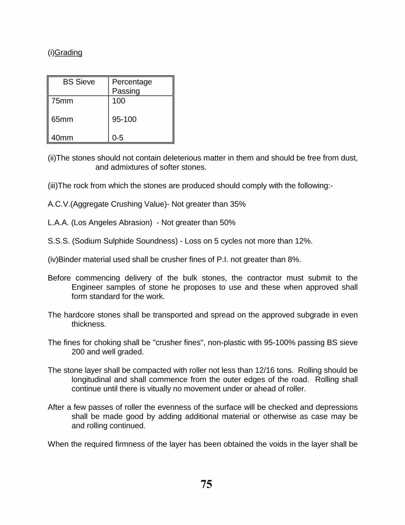
75
(i)Grading
BS Sieve Percentage Passing
75mm 65mm 40mm
100 95-100 0-5
(ii)The stones should not contain deleterious matter in them and should be free from dust,
and admixtures of softer stones. (iii)The rock from which the stones are produced should comply with the following:- A.C.V.(Aggregate Crushing Value)- Not greater than 35% L.A.A. (Los Angeles Abrasion) - Not greater than 50% S.S.S. (Sodium Sulphide Soundness) - Loss on 5 cycles not more than 12%. (iv)Binder material used shall be crusher fines of P.I. not greater than 8%. Before commencing delivery of the bulk stones, the contractor must submit to the
Engineer samples of stone he proposes to use and these when approved shall form standard for the work.
The hardcore stones shall be transported and spread on the approved subgrade in even
thickness. The fines for choking shall be "crusher fines", non-plastic with 95-100% passing BS sieve
200 and well graded. The stone layer shall be compacted with roller not less than 12/16 tons. Rolling should be
longitudinal and shall commence from the outer edges of the road. Rolling shall continue until there is vitually no movement under or ahead of roller.
After a few passes of roller the evenness of the surface will be checked and depressions
shall be made good by adding additional material or otherwise as case may be and rolling continued.
When the required firmness of the layer has been obtained the voids in the layer shall be
76
filled with the crusher fines. The fines shall be spread in thin layer and should be brushed and rolled down into the voids. Water shall be sprayed evenly over the surface during this process to ensure complete filling of all the void.
The finished level of the surface should be true to shape and level specified so that no
point on the finished surface deviates by 20mm of the specified levels. (b)Gravel Base Gravel for base, where specified, shall confirm with the following requirements: (i)California Bearing Ratio(CBR) Minimum CBR after 4 days soak shall be 18%. (ii)Grading The gravel shall have a grading as per grading envelop shown in the attached curve. (iii)Plasticity P.I: 30 maximum. PM. 200 min and 1200 max. (iv)Nodule Hardness Nodule hardness shall be good. Compaction top base course gravel shall be carried out to 98% BS compaction. 8.2.3Wearing Course (a)Gravel Wearing Course (Murram Finish) Gravel shall be from approved source and quarried so as to exclude vegetable matter,
loam, top soil or clay. The gravel shall comply with the requirements of clause 8.2.29 (b) and compaction carried out to 100% BS compaction.
The Contractor shall set out the lines and levels of the edges of the carriage way by
means of wooden pegs or steel pins to the width and levels shown on the drawings or as directed by the Engineer. The distance between pegs shall not be greater than 20m where road is straight and gradient uniform and not more than 10m where the road is on horizontal curves or vertical curve.
77
Gravel wearing course material shall be spread in a uniform layer across the full width
required and scarified so that the maximum size of any particle not greater than one half of the compacted thickness of the layer is excluded. It shall then be mixed, watered if directed by the Engineer, graded and compacted to at least 100% B.S. Compaction and graded to final level. Waterlogged gravel should be allowed to dry to its O.m.c. before it is processed and compacted.
The compacted thickness of any layer shall not exceed 150mm and where a greater
compacted thickness is required and material shall be laid and processed in two layers. Any oversize material, which cannot be broken down to the required size, shall be removed to a soil dump.
The tolerances on levels permitted shall be as follows: Thickness25mm Variation 3m straight edge25mm Camber25mm (b)Premix (Asphaltic Concrete) Finish The premix surfacing shall consist of a prime coat and a 40mm thick wearing course. Prime Coat The primer used shall be MCI applied between the temperature 450C-850c at the rate of 1
litre/m2. 8.2.4Paving Slabs and Kerbstones Precast concrete paving slabs and kerbstones shall be made to the sides indicated in the
Bills of Quantities and the drawings. The casting shall be carried out as specified in section 4 and the laying as specified in clause 7.3.2-open drains.
8.3Fencing All fencing shall be erected in exact vertical position and to straight lines as shown on the
drawings. The materials and workmanship shall comply with the recommendations in BS 1722.
78
8.3.1Concrete Posts Precast concrete posts shall be cast of concrete grade 20 as specified in section 4, to the
sizes shown on the drawings. The posts shall be securely placed in preformed holes and cast in concrete to depths as
shown on the drawings. Bracing shall be provided at all corners, and at intervals of not more than 50metres on
straight lines of fencing. Maximum distance between posts is 2.5m. 8.3.2Chain Link The chain link fencing shall be supplied in rolls of 2130mm(7feet) width and shall be with
65mm mesh of 12 1/2 gauge, fitted to 4 rows of line wires with binding wire at 130mm centres.
The cranked top of the posts shall be fitted with 3 strands of 12 1/2 gauge barbed wire
with four point barbs at 150mm centres. All members of the fencing shall be hot dip galvanized.
8.3.3Gates If not otherwise stated, gates shall be 4metres wide double leaf gates, made from 40mm
galvanized steel tube frame(medium class) with 8 gauge galvanized weld mesh to the frame. Bracing, hinges, tower bolts and locking arrangement shall be as shown on the drawing or of other approved type. the top of the gates shall be fitted with 3 strands of 12 1/2 gauge barbed wire.

79
9 MECHANICAL INSTALLATION 9.1 General The workmanship and the materials covered by this section shall include the supply and
installation of all pumps, mortar and chemical dozer and ancillary equipment. All materials and equipment shall be obtained from reputable manufacturer who have well
established agents in Kenya, local agents shall be able to provide an efficient service of equipment and must have ample stocks of all expendable items such as gaskets, filters fuses, indicator lamps etc.
The Engineer reserves his right to reject any manufacturer or agents who does not fulfill
the above requirements. It is the responsibility of the Contractor to provide evidence that the equipment is in
compliance with this specification and that the equipment will operate satisfactorily, under the conditions under which it is installed.
All equipment offered shall comprise of a complete installation kit such as Bolts, gaskets,
Screens, belt guards etc or the satisfaction of the Engineer. Details of concrete plants for pumps and mortar shall be supplied by the Contractor at
least six weeks before he intends to install the equipment. 9.2 Spare Parts The Contractor shall submit with his tender a guarantee from the supplier that will hold for
sufficient number of spare parts for the maintenance of the equipment. 9.3 Storage of Material The Contractor shall provide weatherproof lock-up sheds for the safe storage and custody
of material for the works, and shall move such sheds and make good damage of disturbed surfaces upon completion to the satisfaction of the Engineer.
9.4 Description of Services The Contractor shall supply, transport, deliver, install, connect, commission and hand
over all equipment and materials specified in the specification, drawing and bill of quantities in a clean complete and in every detailed working conditions.
He shall carry out all tests specified in this specification or in a relevant standard together

80
with any test which might be requested by the Engineer in connection with the use of special materials or equipment.
Further more, the Contractor shall provide guarantee initial free maintenance, instruction
manuals and careful instructions of the Employers staff. 9.5 Maintenance Manual Upon completion, the Contractor shall furnish the Engineer with six copies of a manual
size A4 of loose leaf type containing all the foreign items. Description of equipment Full operation and maintenance instructions Valves operation Fault finding chart Emergency procedures Maintenance and service period Lubricating instructions Primary and secondary spares Recording drawing - size A4 The manual shall be specially written and not a standard manufacturers manual unless
approved by the Engineer. All instructions shall be written into the manual with reference to the drawings. All valves, terminals, controls of the plant shall be labeled to correspond with
maintenance and operation manual. The work shall not be considered to be complete for purposes of taking over until such
instructions and drawings has been supplied to the Employer. 9.6 Motors All motors shall unless otherwise stated be suitable for 415/240 volts 3 phase 50 cycles 4
wire power supply and shall be executed for star-delta starters as specified. The motors shall be constructed in accordance with CP 1015 and shall be protected as
specified in section 10 - Electrical works. The motor speed shall not exceed 2900 RPM. The motor shall be foot mounted squirrel
cage, dump proof or totally enclosed suitable for an ambient temperature of 30oc. The motor shall be designed for continuous running. Each motor shall be capable of an
81
overload of 10% above its rated output and the rated voltage for a period of 1 hr without sustaining damage.
The rated output of motor shall be the maximum horsepower absolved by the pump
under the described conditions of head and discharge plus an allowance for loss of power in coupling. Etc.
Electrically driven pump shall unless otherwise stated be directly coupled via flexible
coupling to the motor and motors and pumps shall be fitted to common rigid steel frames bolted to concrete plains. Proper alignment of mortar and pumps must be guaranteed.
9.7 Engines The engines shall be of diesel type with a maximum speed of 3000 RPM designed for
continuous running. The Engines shall be directly coupled via flexible coupling to the pumps. Engine and
Pump must be fitted to a common rigid steel frame bolted to concrete plinth. Proper alignment of engine and pump must be guaranteed. The engine shall be supplied with hand starter couplings, tachometer, hand throttle control, hand stop control, silencer, fuel tank for at least 300 hours running of the engines and necessary tool kit for minor repair.
9.8 Pumps The pumps shall be of the centrifugal type with Cast Iron casings. The shaft shall be
prepared for direct connection via flexible coupling of the motors. Pump casing shall have interchangeable, bronze wear rings. The impellers shall be of
bronze or high grade cast iron dynamically balance to ensure smooth running. The propeller shaft shall be of steel and fitted with renewable bronze protecting sleeves
wherever it is in contact with the pumped water. Mechanical seals shall be provided unless approved otherwise. It shall be stated in the tender documents if other materials are offered. For horizontal
type pumps, the propeller shaft shall be carried by oil or grease lubricated ball or other bearing if heavy duty type.
The pump casing bearing, shaft, impellers and gaskets must be executed of materials
suitable for many years continuous operation in water system.
82
If materials other than cast Iron, bronze or stainless are included in the pump, it cannot be
approved unless a written guarantee for 10 years performance is produced, giving free checking and replacement in case of fault.
The performance curves efficiency curves and power demand curves (characteristics
curves) shall accompany the tender with clear indicator of the capacity and efficiency of the pump with the specified head.
9.9 Chemical dosing Equipment The chemical dosing equipment shall consist of gravity dosers, tube and connection as
shown on the drawing. 9.10 Pressure Gauges The pressure gauges shall be wall-mounted gauges in metric unit completed with
connection to delivery side of pumps, copper pipe from pipe to gauge supplied with isolating cock.
83
10 ELECTRICAL WORKS 10.1 General The quality of material and workmanship specified in his section is for all items forming
part of Electric Installation as shown in the drawing, bill of quantities and these specifications.
10.2 Regulations All the electrical works carried out strictly in accordance with the following: - i) The 13th Edition of the Regulations for electrical equipment of Building issued by
the Institute of Electrical Engineer of Great Britain with Kenya amendments. ii) The Licenses by-laws The Government Electrical Specification/GES No. 1 and No. 2 The power act The Relevant British standard Specifications and codes of practice published by the
British Institution/here-in after referred to as BS an CP respectively). Specification The contract drawing and the working drawing produced by the Contractor and approved
by the Engineer. The Engineers Instructions. The Contractor shall undertake all modifications demanded by the authorities inorder to
comply with the regulation and produce all certificates if any from the authority without change. After completion of the work the Contractor shall deliver a complete set of as built drawings showing the complete installation including all alterations and modifications. The set of drawings shall include but is not limited to all floor plans and diagrams.
10.3 Material All materials, fittings and accessories are to be new and in accordance with the
requirement of the current rules and regulations where such exist with the relevant KBS standards, BS or others.
The Contractor shall be required by the Engineer to submit samples for his approval
before placing an order. The Contractor will be entirely responsible for all materials apparatus, equipment etc
furnish by him in connection with his work and shall take all special care to protect all parts of finished work from damage until handed over to the Employer.
Competent workmen under skilled and experienced supervision shall carry out the work. The Engineer shall have the right to have any part of the work taken down or changed at
the Contractors expense which is executed in an unsatisfactory manner.
84
10.4 Workmanship The routes of services and approximate positions of operator are shown on the contract
drawings but the exact positions shall be determined by approved dimensional detail on working drawing or on site by the Engineer in consultation with the Contractor.
10.5 Main Switchboard The main switchboard shall be free standing type switchboard with front access. The switchboard shall be constructed fully wired and checked out at the factory and shall
require a minimum of installation work on site, Modular construction shall be used wherever practicable, and provision shall be made for simplified servicing replacement and maintenance throughout without major dismantling.
The enclosure shall be suitable for containing circuit breakers motor starters and metering
equipment from KP&C where spaces on the switchboard are provided for future circuit components, all ancillary ports shall be installed initially. Full safety precautions shall be provided in all cases.
10.6 Switch gear The switchgear for others apart from boreholes will be as per clause 2 where applicable. 10.7 Motor Starters Motor starters for the backwash pumps shall be automatic direct on line. Contractor type
fitted wire double pole incoming mechanically interlocked circuit breaker housed in a damp and dust proof steel enclosure.
10.8 Wiring All wiring must be carried out in PVC single core copper cables to BS. 10.9 Cable and Conductors All cables shall conform to relevant BS. No cable dimensions shall be smaller than 1.5sq.
mm for light and control circuits shall be used. All low voltage cables shall be thoroughly soldered or joined with connectors of absolutely
reliable type which hold the conductors in a firm grip, without damaging the wire and without any possibilities of the vibrating loose.
10.10 Conduits Plastic conduits shall be of the best quality new super high impact grade, heavy gauge
class "A" rigid PVC, suitable for plain connection.
85
In no case shall conduits smaller than 20mm shall be used. 10.11 Boxes All conduit boxes in connection with plastic Conduit shall be of plastic. All boxes shall
match to the equipment installed in the box. 10.12 Light fitting All light fittings shall be cleared and installed in complete working order before handing
over. 10.13 Light Switches Light switches shall be 5 or 20 Amperes according to the load switches 10.14 Power Installation The installation for power shall be concealed in wells and floors in PVC conduits. All
adaptors shall be solid bronze or brass pattern with standard thread. 10.15 Earthing and Bonding Earthing and bonding shall be carried out to the requirement of the current 14th edition of
the TEE regulation and GES 1 and 2. In particular attention is drawn to IEE regulation D5, D6, D7 and D29.
10.16 Testing All tests prescribed in the 14th Edition of the regulations for the electrical equipment of the
Institution of Electrical Engineers, together with all amendments as applicable, shall be carried out by the Contractor on the completed installations.
10.17 Handing Over The Contract works shall be considered complete and the maintenance and defects
liability period shall commence only when the contract work and supporting services has been tested, commissioned and operated to the satisfaction of the Engineer and officially approved and accepted by the Employer.
86
11 BOREHOLES
Application for drilling of a borehole shall be submitted by the client to the relevant
authority upon which hydrological survey will be carried out by a qualified hydrogeologist.
The survey report will include among other things the geophysical site, expected water
level, yield, quality and soil formations etc. 11.1 Drilling Drilling shall be done by a registered Borehole drilling contractor with the relevant
authority (MENR). 11.1.1 Diameter of Boreholes All boreholes shall be straight, vertical and shall be drilled to provide for a finished
borehole of at least 152mm cased diameter after allowing for 50mm thick gravel pack and temporary casing as found necessary.
11.1.2 Materials Gravel pack and tests (copy) All materials used in the borehole construction other than temporary works shall comply
with the relevant standards specifications. A tolerance dimensions will be permitted provided that the material quality is not inferior to specification and the works is in no way impaired.
11.1.2.1 Borehole Casing (Steel) Borehole casing shall be made from steel pipe manufactured to API specifications 5L or
BS 3601 and of internal diameter 152mm and 4.0mm thick. Casing shall be epoxy coated and lined to American standard WWAC 213/C 210 or BS
BGC/PS/CW6 or German standard DIN30671 or any other Internationally recognized standard to resist underground colosion
Casing shall have self-centering sockets and spigot ends for fillet to prevent damage to
the internal epoxy lining and supplied in 6m length. 11.1.2.2 Borehole Screens Screens shall be slotted steel pipes manufactured to API specification 5L or BS 3601 11.1.3 Borehole Construction The contractor shall install plain steel casing and screens to the required depth, install
87
gravel pack of 2 - 4mm thickness to annular thickness of 50mm around the casing or as specified by the Engineer. The bottom of the production casing shall be sealed by welded steel plug of 6" diameter and 4mm thickness.
The Contractor shall be responsible for the provision of temporary casing as necessary,
insertion and removal of which shall be at his cost. 11.1.4 Borehole Development After insertion of the casing, screen and gravel pack each borehole shall be developed to
clear gravel pack and clean and develop the aquifer method of development and time spent as proposed by the Contractor must be approved by the Engineer.
The methods of development shall be chosen among the following; - Surging and pumping - Hydraulic jetting, single pipe system open to atmosphere. 11.1.5 Test Pumping After development of the borehole is complete, test pumping for yield shall be carried out.
The Contractor shall provide and install the necessary pumping equipment capable of pumping the estimated yield against the estimated head below ground level but with suitable throttling devises so that the discharge may be reduced.
The pumping unit shall be complete prime mover and all auxiliaries shall be capable of
being operated for a period of 24 hrs uninterrupted. It shall also have all discharge pipework and suitable discharge measuring devices subject to approval of the Engineer.
On completion of the test pumping the borehole shall be caped by a welded cap of 6"
diameter and 4mm thickness. 11.1.6 Water Sample The Contractor shall be responsible for taking samples of water at the end of test
pumping of boreholes for bacteriological and chemical testing to a competent and authorized laboratory. The water samples shall be supplied in sterilized containers of not less than 300ml for bacteriological test and a five litres clean container for chemical tests.
11.1.6.1 Boreholes Disinfection The boreholes are to be disinfected after development and test pumping, additionally
wherever a borehole for human consumption has been temporary out of use the Borehole shall be disinfected before production resumes.
The Contractor is supposed to keep his drilling equipment in normal hygienic condition
and the Engineer can demand the equipment to be disinfected.
88
11.1.7 Borehole Civil Works 11.1.7.1 Gantry Gantry of 7.1 m height above the ground shall be provided and fabricated from DN
150mm flanged class B water pipes they shall have a hook on the top beam for chain block under ascending steps made from DN13mm GS water pipes on both column. The Gantry shall be finished in a heat resistant non-peeling of Aluminum paint.
11.1.7.2 Storage Tank A suitable storage tank as approved by the Engineer will be constructed with a capacity of
at least 50% of the daily water demand as required in standard design manual of the MENR shall be provided.
11.1.7.3 Pump House A standard pump house as approved by the Engineer shall be constructed. The standard
drawing of pump house shall be provided upon request by the MENR. 11.1.7.4 Water Trough Livestock water troughs as approved by the Engineer will be constructed at 50m from the
borehole. 11.1.7.5 Communal Water Point A Communal water point as approved by the Engineer shall be constructed at 10m from
the Borehole with a standpipe and proper drainage shall be allowed. A concrete approx. of 2x3m shall be provided around the borehole. Security fencing shall be provided by the Contractor as approved by the Engineer. 11.2.0 Borehole Equipment 11.2.1 Pumping set and associated switch gear The pumping sets shall be multistage centrifugal type running a full load speed of not less
than 2850RPM. The entire pump set body (Dump and Mortar), including the Impellers, Strainer, Cable guard, non-return valve shall be made of heavy duty stainless steel material.
AISI 316 or equivalent heavy duty grade stainless material grade. The bearing shall be
water lubricated type, water resistant. The pump efficiency at the duty point shall not be less than 58%.
89
The motor shall be a two pole canned asynchronous three phase, 415 VAC squirrel cage Induction type. It shall be continuously rated and of minimum class B insulation.
The pump set shall be supplied complete with the Cable, water tight cable, connector
splicing unit. 11.2.2 Switch gear Switchgear shall be 3 phase, 415 VAC, 50 HZ. It shall be in water tight, front access
hedged door colosion, resistant, lockable metal enclosure, comprising of the following components among other fully wired and labeled.
The starter shall be of high quality durable type e.g. ASEA, MEM, CRABTREE,
SIEMENS, etc - Appropriate rating Contactor - Appropriate thermal over load. - Start stop/resist push button - Integral TPN MCCB (MCB) type 3 - Over/under voltage and phase failure protection relay set at 380 and 450 VAC - Water level control relay - Pilot indication light (green marked pump run red marked overload - Tripped
yellow marked borehole low - Hours run counter range 0 - 99999 hrs - Cable terminal blocks All switch gear enclosures shall be fabricated from heavy gauge spangled galvanized
glass protected sheet steel of minimum thickness of 1.5mm they shall be finished to tone heat resistant impeeling of stove grey enamel paint or epoxy powder coating.
11.2.3 Electrical generating set and associated switch gear. Generating sets and switch gear shall comply with the following conditions: Generating sets and switch gear shall be tropicalised able to operate continuously at their
full load at the stated site climate and geographical conditions. The generating set upto and including 22.4 KVA shall be air cooled and hand crank
started and those above 22.4 KVA shall be both electric and hand crank started and water cooled.
The engine and the alternator shall be directly coupled and mounted on a robust vibration less steel base frame with coupling protection guard lifting eyes and mounting holes, fuel and terminals connected to the engine fuel pump. The set shall be supplied with appropriate strength size bolts, washer and nuts.
The generating set shall have a full load speed of 1500 RPM. 11.2.3.1 Engine

90
The engine shall be heavy duty 4 stroke direct injection cold starting type under the stated
site conditions of latitude ambient temperature and humidity, the engine shall be able to operate for continuously and efficiently at the rated power
11.2.3.2 Electrical Starting System This is recommended for Generating set of rated 22.5 KVA and above. The electric
starting up system shall either be 12VDC or 24VDC completely wired labeled and comprising of the following components among others;
a) Heavy duty starter mortar Terminal and associated cables Full charged heavy duty batteries ( load acid or Nickel cadminium) Trickle charge unit Automatic cut-off device full charge The engine key start switch system and charger panel comprising of DC battery charger
ammeter, DC voltmeter, battery low indication lights, charger fault indication light.
On sudden application of full load rated at 0.8 laging PF (power factor) the voltage recovery to within 3% of the steady state value shall be within the range of 0.2 seconds.
The alternator shall be able to sustain overload equivalent to a full voltage current of 3 times full load rated volume for 5 seconds depending on voltage and output.
The phase sequence shall be red, yellow, blue for clockwise rotation when viewed from the dry end.
The alternator shall be protected against radio frequency interference. The alternator stator core assembly shall consist of insulated low loss electrical sheet
steel lamination jig build and welded under controlled pressure to withstand Engine vibrations and load/fault induced forces, pressed into the frame and torque pinned. The frame shall be cast steel type
Head treated monitoring steel brackets at least 3 Kg of fine resistant heat laying wire material.
11.2.3.3 Exhaust System The Exhaust system shall comprise of the following: - Exhaust silencer Flexible/rapid heat treated steel exhaust piping (minimum 2m), flexible bellows, 1m of
heat treated steel pipe and shall be able to deliver power in excess of 10% higher its rated value for 1 hr in any period of 24 hrs consecutive running.
The specific fuel consumption shall not exceed 0.3l per kW/h.
91
The fuel system shall be gravity feed type and fuel tank shall be constructed from rust protected steel material of minimum thickness 1.75mm and zinc coated. All surfaces shall be cleaned primed and finished in gloss enamel.
Fuel tank shall be of a capacity to last 12 hrs of continuous operational at full load
complete with wall mounting GS bracket (wall mounting type, fuel content gauge, fuel cap, drain cork, vent pipe, 3m of steel/copper fuel feed and leak return line complete with fittings.
The engine starting system shall be either manual hand crank, electric or both. Hand crank starting shall be applicable to generating sets rated upto 22.5 KVA and shall
comprise of a high quality, durable hardened steel crank tool with handle. 11.2.3.4 Alternator Alternator shall be heavy duty industrial 4 pole 3 phase 415/240VAC 50/60HZ 4 wire
series-star connected type. It shall be brushless self exiting. Self regulating drip proof screen protected continuous
related at full load class H insulation. The alternator shall meet the following conditions among others.
Voltage regulations shall be maintained within the limits of +- 2.5% from low load to full
load including cold and hot variations at any power faction, between 0.8 lagging and unit inclusive of speed variation of + or - 3%.
The total RMS wave form distortion (line to line and line to Neutral) shall be of order 2%
on open circuit and the corresponding on load figure of 3.5% and the bearing shall be ball bearing type sealed for life.
11.2.3.5 Instrumentation and switch gear Cubicle The generating and switch gear cubicle shall be mounted on a vibration less frame and
will comprise of the following components among others fully wired and labeled; 1No. 75x75mm flash mounting AC voltmeter range 0 - 500VAC couple with phase
selector switch and protection fuses. 3No. 75x75mm flash mounting AC meters with 3No. current transformer (for generating
sets rated 20 KVA and above). 415 VAC TPN type 3 MCCB (MCB) type Dorman MEM, SIEMEN, ASEA or any other as
recommended by the Engineer. Frequency range meter 45 - 65 HZ. Hours run Counter (240 VAC) range 0 - 99999 hrs. Engine low pressure, Engine high oil temperature , Engine high water temperature,
radiator water level low, Over/low speed automatic shutdown protection devices with associated ED or CRYSTAL LIQUID indicator lights cable terminal blocks.
92
12 SHALLOW WELLS 12.1.1 Diameter and Depth The diameter of a dug well shall be at least 1.2m to allow two men to work together during
the digging. Slightly smaller diameter may be used if digging is to be done by one man only.
The wells shall be dug at least 3m below the expected water level. 12.1.2 Lining Most dug wells needs an inner lining of materials such as Brick, stone masonry, concrete
rings, cast in-situ or pre-cast concrete rigs. Backfiilled dug wells with 100 - 150mm can also be a good solution.
- Sinking a dug well by excavation from the inside is very often a good and safe
technique however in very loose soil (fine or medium sand) in thick layers over 3 m other methods for instant hand drilling shall be used.
- In consolidated ground (e.g. Rock) the well may stand unlined but the upper part should always have a lining.
- The section of the well penetrating the aquifer requires a lining with opening or perforations to allow the groundwater to enter.
- Any backfilling at the same level as the aquifer should be made with the gravel. - However, in fine and sand aquifers, the lining should be without perforations and
the groundwater should enter only through the bottom of the well. - The bottom should be covered with graded gravel e.g. 3 layers each 150mm thick
with grain sizes 1 - 2mm for the deepest layer than 4 -8 mm and 20 - 30mm effective size at the top.
12.1.3 Protection The space between the walls of the dug well and the lining should be sealed with puddled
clay or with cement grout. The sealing should be between the ground surface and the aquifer or down at least 2m below the ground surface.
- The wall lining should be extended approximately 0.5 m above the ground to form
a wall round the well. - A concrete apron should be constructed on the ground surface about 2m all round
the well. - The well top should be sealed with watertight slab. - A manhole that can be tightly and securely locked shall be provided for Inspection
and Disinfection.

93
HYDRO GEOLOGICAL SURVEY
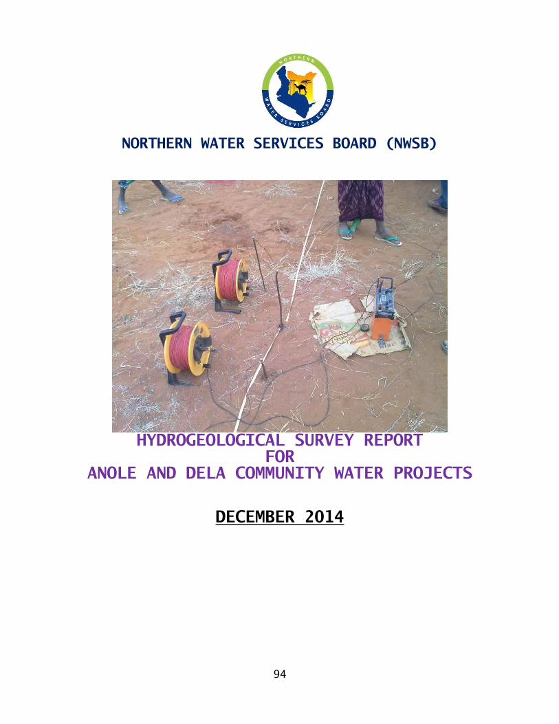
94
NORTHERN WATER SERVICES BOARD (NWSB)
HYDROGEOLOGICAL SURVEY REPORT
FOR
ANOLE AND DELA COMMUNITY WATER PROJECTS
DECEMBER 2014
95
`
HYDROGEOLOGICAL SURVEY REPORT
CLIENT:
THE FUND MANAGER
ELDAS CONSTITUENCY DEVELOPMENT FUND
P.O. BOX
WAJIR
PROJECT: ANOLE AND DELA COMMUNITY WATER SUPPLY PROJECT
CATEGORY: OFFICIAL L.R. NO. – NOT SURVEYED
LOCALITY: ELDAS AREA
DISTRICT: WAJIR WEST
SELECTED BOREHOLE SITE
LOCATION COORDINATES
Map Sheet No. Series SK 81-A
02.5025100 N
39.5663260 E
ELEVATION: APPROXIMATELY 423m ASL BY GPS METER
INVESTIGATING GEOLOGISTs H.K. KAMUNGE/M.O. AMIMO
Contents ABBREVIATIONS AND GLOSSARY OF TERMS ......................... 97
1.1 .......................................................................................... GLOSSARY OF TERMS .. 97 INTRODUCTION ............................................... 101
96
2.1 ....................................................................................................... HYDROGEOLOGY . 101 PROJECT LOCATION ........................................... 103
3.1 .................................................................................................................. Location . 103 3.2 ................................................................................ Nature of the Project . 103 3.3 .......................................................................................... Project Ownership . 103 3.4 ......................................... Site alternative and proposed action . 103 3.5 ....................................................................................................... PhysiographyError! Bookmark not defined.
HYDROLOGY, HYDROCHEMISTRY AND STRUCTURAL GEOLOGY ........... 104
4.1 .............. Recharge Mechanisms within the Aquifer Systems . 104 4.2 .................................................................................................................. Drainage . 104 4.3 .................................................................................................................... Climate . 104 4.4 ....... Geobotany, Geochemistry and Stratigraphic History . 104
GEOPHYSICS: ................................................ 105
5.1 ....................................................................................................... Introduction . 105 RECOMMENDATIONS AND CONCLUSIONS ............................ 107
6.1 ..................................................................................... Recommended BH site 108 Appendix 1 ................................................. 109
VES/IP 002/2012 ......................................... 110
VES 002/2012 ............................................ 110
The modeled geophysical curve ........................... 110
VES 003/2012 ............................................ 111
VES 004/2012 ............................................ 112
VES 005/2012 ............................................ 113 APPENDIX II - LICENSED BOREHOLE CONTRACTORS IN KENYAError! Bookmark not defined.
APPENDIX III - Drilling .................................... 114
9.1 .......................................................................................................... Well Design . 116
Casing and Screens ...................................... 116 9.2 .......................................................................................................... Gravel Pack . 116 9.3 .......................................................................................... Well Construction . 117 9.4 ............................................................................................. Well Development . 117 9.5 ....................................................................................................... Well Testing . 119 9.6 ........................................................................................Legal Requirements . 120 9.7 ..................................................................................................... Pumping Plant . 120
97
1.0 ABBREVIATIONS AND GLOSSARY OF TERMS
ABBREVIATIONS (S.I. Units throughout, unless indicated
otherwise)
agl above ground level
amsl above mean sea level
bgl below ground level
E East
EC electrical conductivity (S/cm)
hr hour
l litre
m metre
N North
PWL pumped water level
Q discharge (m3
/hr)
s drawdown (m)
S South
SWL static water level
T transmissivity (m2
/day)
VES Vertical Electrical Sounding
W West
WAB Water Apportionment Board
WSL water struck level
S/cm micro-Siemens per centimetre: Unit for
electrical conductivity
°C degrees Celsius: Unit for temperature
" Inch
1.1 GLOSSARY OF TERMS
Alluvium General term for detrital material deposited by flowing water.
Aquiclude An impermeable geological formation or structure, which transmits little or no water.
Aquifer A geological formation or structure which stores and transmits water and which is able to supply water to wells, boreholes or springs.
Back reef Landward side of a reef, including the area and the deposits between the reef and the mainland/. Deposits are usually a mixture of terrestrial and marine materials, originating from respectively the landward and seaward sides.
Coastal Plain Plain of low elevation along the coast usually
98
composed of ~unconsolidated fluviatile or marine sediments.
Colluvium a General Term for detrital material deposited by hill slope gravitational processes, with or without water as an agent, usually of mixed texture.
Conductivity Transmissivity per unit length (m/day).
Confined aquifer A formation in which the groundwater is isolated from the atmosphere by impermeable geologic formations. Confined water is generally at greater pressure than atmospheric, and will therefore rise above the struck level in a borehole.
Consolidated Said of a deposit that has become firm and coherent (as opposed to unconsolidated).
Delta Deposit of sediments made by a stream at its place of entrance into an open body of surface water (sea or lake).
Development In borehole engineering, this is the general term for procedures applied to repair the damage done to the formation during drilling. Often the borehole walls are partially clogged by an impermeable “wall cake”, consisting of fine debris crushed during drilling, and clays from the penetrated formations. Well development removes these clayey cakes, and increases the porosity and permeability of the materials around the intake portion of the well. As a result, a higher sustainable yield can be achieved.
Drawdown The lowering of the water level in response to pumping. When water is pumped from a well or borehole, the level goes down: the resulting gradient is the driving force that makes water flow towards the well. The lower the drawdown under a given discharge, the higher the capacity of the source.
Evaporation Loss of water from a land area through transpiration from plants and evaporation from the surface.
Gradient The rate of change in total head per unit of distance, which causes flow in the direction of the lowest ~head.
Head Energy contained in a water mass, produced by
elevation, pressure, and/or velocity.
Heterogeneous Not uniform in structure or composition (as opposed to homogeneous).
99
Hydraulic head Energy contained in a water mass, produced by elevation, pressure or velocity.
Hydrogeological Those factors that deal with subsurface waters and related geological aspects of surface waters.
Infiltration Process of water entering the soil through the ground
surface.
Interface Boundary surface between two bodies of different physical and/or chemical properties. Here used for the contact between fresh and salt water: saline interface.
Lacustrine Referring to generally fine-grained, lake deposits
Lagoon Elongated an shallow tidal depression between the coast line and an offshore bar, barrier or reef, which separates the lagoon from the open sea.
Limestone Carbonate rock consisting almost entirely of calcium-
carbonate (CaCO3)
Marl A mixture of limestone and clayey material.
Perched aquifer Unconfined groundwater separated from an underlying main aquifer by and unsaturated zone. Downward percolation hindered by an impermeable layer.
Percolation Process of water seeping through the unsaturated zone, generally from a surface source to the saturated zone.
Permeability The capacity of a porous medium for transmitting fluid.
Piezometric level An imaginary water table, representing the total head in a ~confined aquifer, as defined by the level to which water would rise in a well.
Porosity The portion of bulk volume in a rock or sediment that is occupied by openings, whether isolated or connected.
Pumping test A test that is conducted to determine aquifer
and/or well characteristics.
Recharge General term applied to the passage of water from surface or subsurface sources (e.g. rivers, rainfall, lateral
100
groundwater flow) to the aquifer zones.
Reworked Sedimentary particles, fossils etc. that have been eroded from an older formation and incorporated in a younger one.
Salt water intrusion Encroachment of saline water into the fresh water zone, either in a lateral or vertical direction. Often induced by man-made (over-) abstraction from wells and boreholes.
Specific capacity The rate of discharge from a well per unit
drawdown.
Static water level The level of water in a well that is not being affected by pumping. (Also known as "rest water level")
Transmissivity A measure for the capacity of an aquifer to conduct water through its saturated thickness (m2/day).
Unconfined Referring to an aquifer situation whereby the water table is exposed to the atmosphere through openings in the overlying materials (as opposed to ~confined conditions).
Yield Volume of water discharged from a well

101
2.0 INTRODUCTION
The borehole sites are within Eldas Town in Wajir west District, located some 130 Kilometers to the northwestern sides of wajir town/ Centre, and approximately 30 kms away from Della Township on an all-weather stretch, which weaves its way through a series of hills and plains. This is along Wajir –wagalla-tulatula-malka gufu-buna Road. We surveyed the riverine locality along the tributary course way, and and several other sites within Dela and Anole as well. The area has an abundance of drainage, mainly off-shoots of several laghas, and the thermal gradients are almost 40 degrees. Anole and Dela area did not have a promising site, and as such, we sought the advice of the area chief as to where next we could locate the site for the two centers. He took us downstream of a lagha, located westwards, 2km away from Eldas Town. Some 7-10 cubic meters per hour discharge, or even more, of water, would be available from the well, and this would be sufficient for the task at hand. In order to meet the demand for the Two centres and for augmentation of Eldas Town water supply, about 4 sites were located.
2.1 HYDROGEOLOGY
The Project Area is dominated by thick successions of light to dark complexioned Miocene-Pliocene Sediments and Calcareous/Jurassic Limestone series, overlying the highly to slightly weathered Basement gneisses. The climate characteristic is typical of the desert climatic parameters, at least from the Biogeography. In the upper Stratigraphic columns, there are sequences of weathered gneisses, laterites, sandstones, gravels, and calcareous sediments, mainly in the 30-80m bgl depth range and in the 80-125m depth range. There is a minor fracture in the 125-175m depth range, from the geophysical curves generated. The major recharge parameter will be the flow within the well-defined fault line recharging the existing Borehole. The waters likely to be found here are derived of meteoric origin, from the annual episodes of rainfall. In the upper depths before 100m, no weathering influence is picked upon the geophysical curves generated. The units are fractured at these depth ranges, and are responsible for storage of juvenile waters that are deemed Syngenetic in formation as the parent aquifer rock units. The storage of the juvenile waters would be in the depths 50-125m, mainly within mineralogical sequences rich in calcareous sediments, biotite gneisses, hornblende gneisses, granitoid gneisses and the hybrid units of hornblende-biotite gneisses. Some of
102
these Precambrian species are quite highly weathered at these depth ranges. Groundwater storage in the upper sediments would be within these weathered outfits and the Fluviolacustrine deposits of Quartzites, laterites, granitoid gneisses and the gravels. In the lower deep-seated aquifers, the replenishment to the borehole would be through flow of other regional aquifer bodies into the borehole. The poor degrees of fracturing render the area a moderate groundwater potential zone. In summary, groundwater in the upper sediments shall enjoy annual precipitation recharge through direct infiltration, while the deep-seated zones shall be recharged via regional flow aided by the northwest-southeast trending minor fault. Evapo-transpiration rates of up to 2,000mm per annum over- shadow the annual rains of up to 600mm per annum.
103
3.0 PROJECT LOCATION
3.1 Location
The project area, Eldas, lies within the Wajir west District situated in the N. E. Province of Kenya within the Wajir County and is headquartered at eldas town, which has a DC. It is located on the southwestern sides of the main catchments course way, some 130 kilometers away from Wajir. The area is defined by longitudes and latitudes 39.566320E and 02.502510N respectively at an altitude of approximately 423m above sea level. Oblique dipping sediments litter the terrain, comprising mainly the flood-prone Miocene Pliocene sediments.
3.2 Nature of the Project
This is a community project meant to enhance the rapid settlement of the local populations by having rapid absorption of children into schools for academic and spiritual growth. At the moment, settled life is in place, but a good number of the locals are still in the bush herding livestock. The project shall have a daily requirement of approximately 200 cubic meter of water, computed from the population figures. This is a figure presumed to include daily domestic requirements as well. The borehole will be developed upon drilling completion and should be preferably encased with steel iron-casings. Once the productivity of the borehole has been determined, a suitable submersible pump will be installed to pump water into the proposed storage tanks. The schematic design and the detailed itemization for the proposed borehole shall be the subject of phase two work for the planning and designing unit, but shall be predicated on the borehole performance in terms of aquifer yields and recharge.
3.3 Project Ownership
The proposed site is a public facility owned by the residents of Eldas constituency. At an appropriate stage, the community will be trained on management related issues pertaining to sanitation, as well as borehole operations and maintenance.
3.4 Site alternative and proposed action
All the surveyed sites are productive in equal measure, but the recharge potential is higher in the area located 7.0 kilometers away from town. The area within the centre has potential, but remarkably brackish, that is to say unbearably saline.
3.5 Physiographic
The area stands at an average altitude of 423 Metres above sea level within a gently dipping terrain punctuated with several major hills, dry ephemeral courses, and flood plains both on the south eastern and north western flanks. The rivers
104
radiate from the Moyale and Marsabit areas and the Ethiopian Highland
4.0 HYDROLOGY, HYDROCHEMISTRY AND STRUCTURAL
GEOLOGY
4.1 Recharge Mechanisms within the Aquifer Systems
Very little geological & structural evidence avails itself for scrutiny, of faulting, shearing and fracturing of the Jurassic sediments on the surface, alluding to moderate forces of Global tectonics. Much of the north westerly – southeasterly directed stress fields helped sculpture the terrain into its present geological state. This plate tectonic-attributed phenomenon post dated a major eruption in the Ethiopian Highlands. Several large catchment basins formed after the event, the major reservoir components of which are mainly the highly porous and permeable weathered gneisses. As a result, most streams in the area are ephemeral. Owing to the relatively low fractions of clays in the upper beds, there is a zero possibility of the borehole water stuck occasioning bacteriological contamination. Also, the great depths at which the reservoirs form offer no favorable thermodynamic parameters to aid the biological processes responsible for such a scenario. The aquifers are not prone to biological contamination, as no human settlements had ever been established there.
4.2 Drainage
The drainage is predominantly dendritic, with water flowing from the hills into the Ethiopian highland Catchments catchment zone into the Kenyan portions in Gurar Hills, Basanija, Dunto, Qudama, Bute, Danaba, and the many other ephemeral stream Courses. Owing to the relatively flat nature of the terrain, there are high flooding risks. Understandably, flooding takes place occasionally, at the expense of the lives of both livestock and human persons. This is normally from the fast-flowing ephemeral streams.
4.3 Climate
The project area falls within zone 7 of the classification of climatic/ecological zones of Africa, that is to say arid to semi arid with temperatures averaging 30 to 34 degrees per day and occasioning evapo-transpiration rates of up to 2000mm per annum. The rainfall average falls well below 600mm per year. In the evenings, however, the temperatures may fall to absolute zero, thus initiating freeze thaw shattering, thereby exfoliating rocks.
4.4 Geo botany, Geochemistry and Stratigraphic History of the Eldas sediments
At the eldas sites investigated, it is noted that a good number of the acacia- allied tree species are growing along a certain pattern or geometric orientation, parallel to the river flow-course. These trees are spaced at an interval averaging
105
20 to 50m apart. There is a higher density of these trees as one nears the river courses, albeit dry ones. A close study of the surface geomorphology and/or Geo botany suggests that the project area is located in the minor fault line that runs across. The trees growth would naturally be impeded by saline environment-induced ensuing reverse osmosis, a process that would drain the plant transport system of all its vital metabolic water within the xylem and phloem tubes. The fact that these trees grow here is a testimony to the relative absence of anomalous salinity levels and cements the fact that a river or a lake system did traverse this terrain in the geological periods pre-dating the tectonics accompanying the Precambrian Orogeny.
5.0 GEOPHYSICS:
5.1 Introduction
In order to determine the Projects Area’s hydro-stratagraphy and aquifer suitability, a total of 5No. Vertical Electrical Soundings were undertaken using an ABEM SAS 4000 Terrameter. Schlumberger arrays were used so that current electrode spreads of up to 250m against potential spreads of between 5m and 25m were employed to conduct the surveys. Copper electrodes were used for the potentials, while steel iron electrodes were used for the currents.
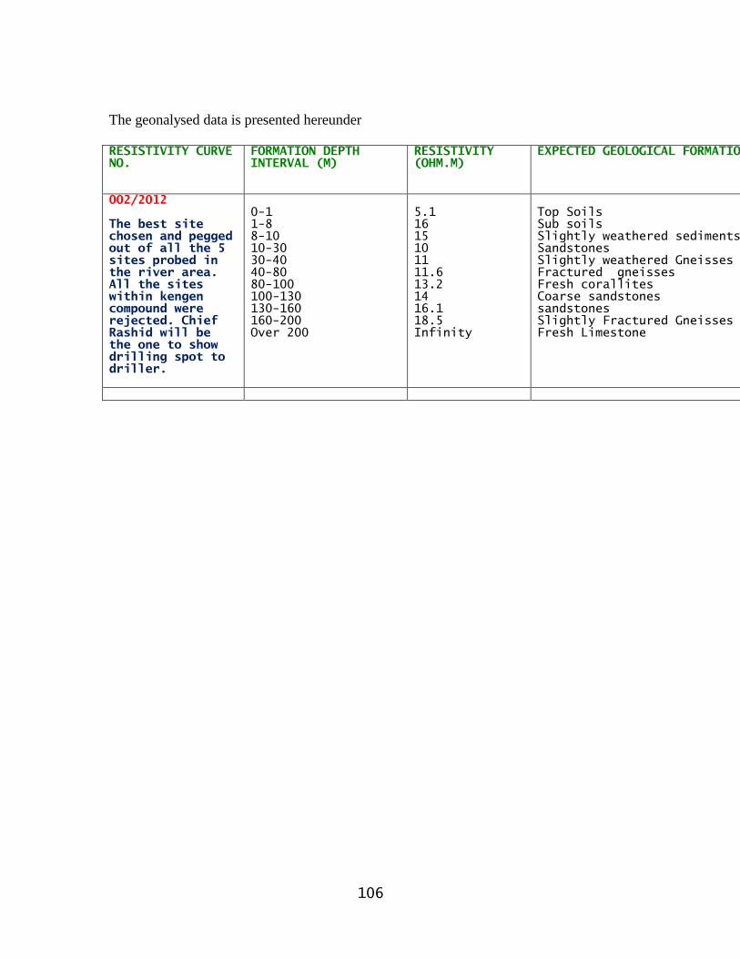
106
The geonalysed data is presented hereunder
RESISTIVITY CURVE
NO.
FORMATION DEPTH
INTERVAL (M)
RESISTIVITY
(OHM.M)
EXPECTED GEOLOGICAL FORMATION
002/2012
The best site
chosen and pegged
out of all the 5
sites probed in
the river area.
All the sites
within kengen
compound were
rejected. Chief
Rashid will be
the one to show
drilling spot to
driller.
0-1
1-8
8-10
10-30
30-40
40-80
80-100
100-130
130-160
160-200
Over 200
5.1
16
15
10
11
11.6
13.2
14
16.1
18.5
Infinity
Top Soils
Sub soils
Slightly weathered sediments
Sandstones
Slightly weathered Gneisses
Fractured gneisses
Fresh corallites
Coarse sandstones
sandstones
Slightly Fractured Gneisses
Fresh Limestone
107
6.0 RECOMMENDATIONS AND CONCLUSIONS
From the foregoing synthesis of Eldas Area’s hydrology, geophysics, hydrogeology and stratigraphy, the sites investigated bear moderate groundwater potential. The 5No sites investigated possess reliable borehole potential. The client is hence advised to sink 1No borehole at the pegged spot site Reference No eldas-002/2011 the last site we visited in the lagha zone with chief rashid hassan to a maximum depth of 175 meters. These sites are known to area chief, mr rashid hassan. It is also approximately sketched in the attached Map Extract. Other recommendations include:- (i) Installation of an Airline (Piezometer) in the borehole to aid regular
measurements of Static Water Levels. (ii) Installation of a Master Meter in the borehole to aid the measurement of
groundwater abstraction rate periodically. (iii) Undertaking a full Physical, Chemical and Bacteriological Analyses of
water samples collected from the borehole before assigning it any use. (iv) The formations bearing or harboring water are either very loose or highly
weathered. It would be thus prudent to deploy a mudflow rotary rig or a cable tool percussion one to do the drilling.
(v) The community should insist on supervision by a Government or Board Officer through out the Drilling.
Piecemeal shipment of vital drilling materials like temporary casings, drilling foam, bentonite, screens, et cetera, must never be condoned. All these must be first at site before commencement of drilling in order to avoid borehole collapse occasioned by delayed execution midway through the drilling progress.
B.M.O AMIMO
HYDROGEOLOGIST
NORTHERN WATER SERVICES BOARD
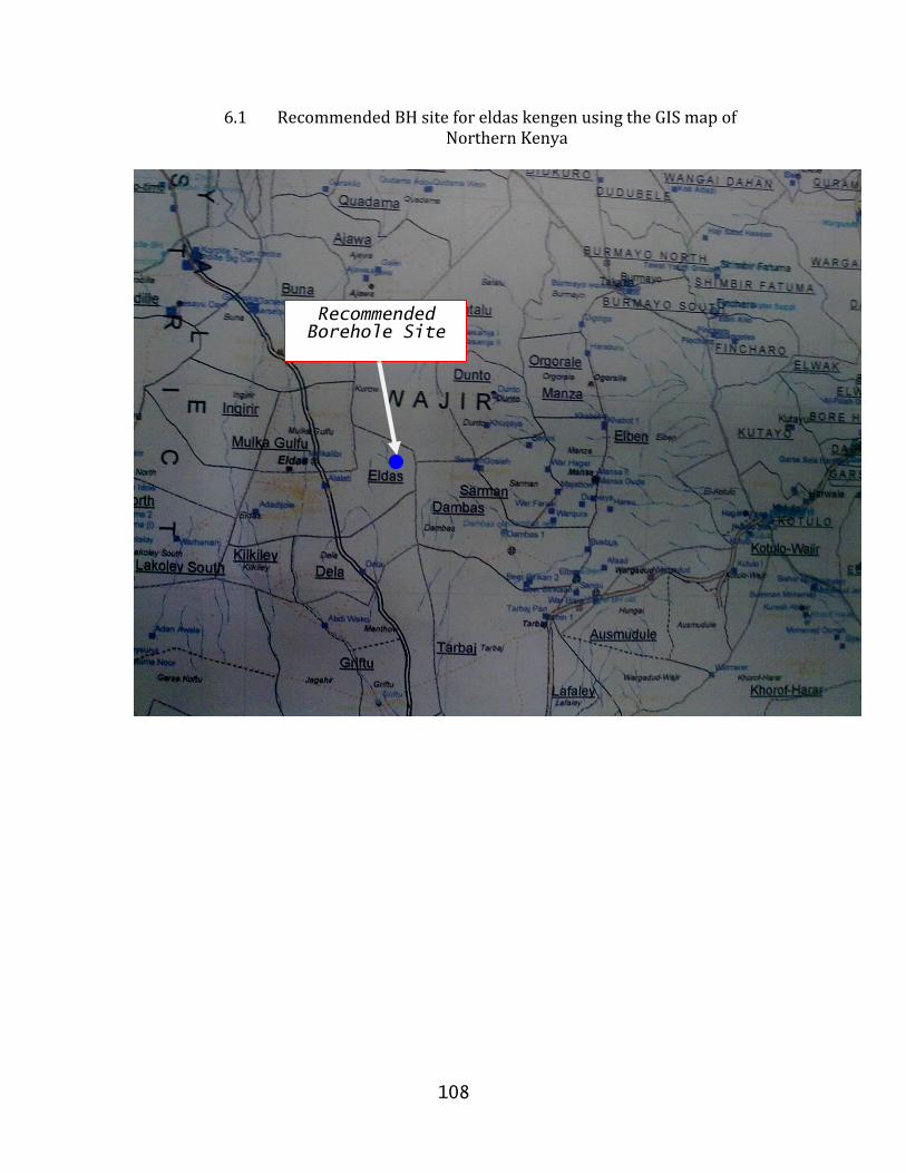
108
6.1 Recommended BH site for eldas kengen using the GIS map of Northern Kenya
Recommended
Borehole Site

109
7.0 Appendix 1
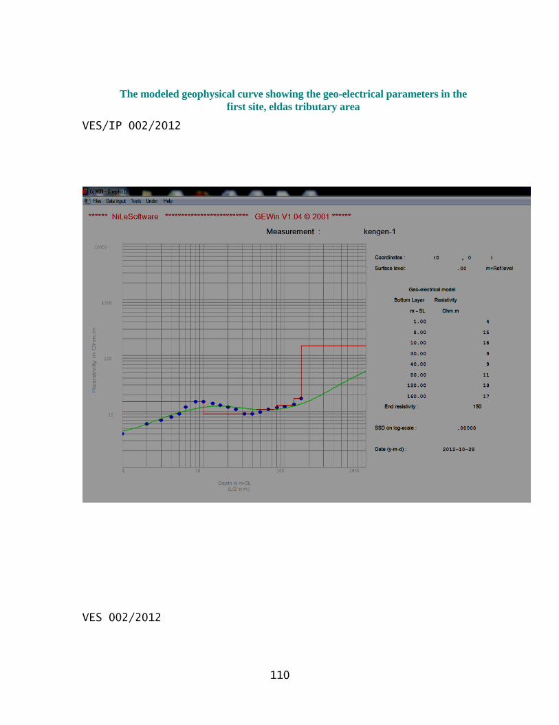
110
VES/IP 002/2012
VES 002/2012
The modeled geophysical curve showing the geo-electrical parameters in the
first site, eldas tributary area
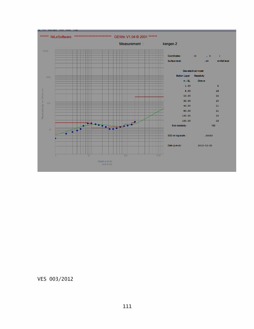
111
VES 003/2012
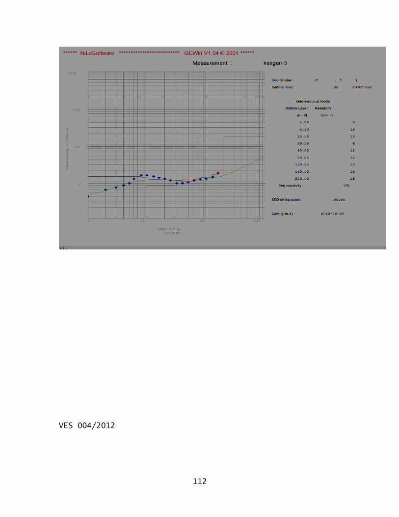
112
VES 004/2012
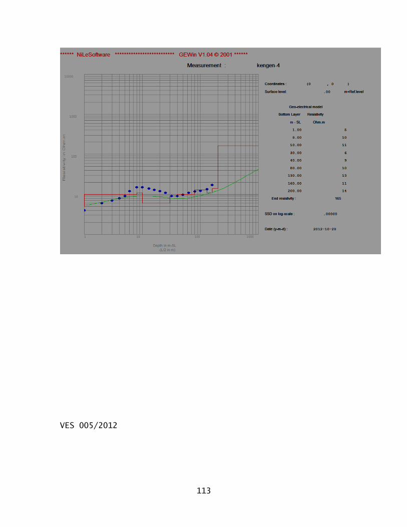
113
VES 005/2012
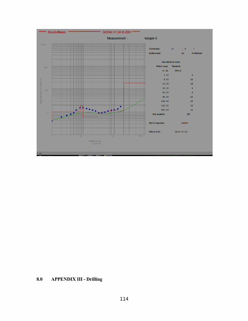
114
8.0 APPENDIX III - Drilling
115
Drilling should be carried out at a diameter of not less than 10”, using a rotary type machine. The drilling rig should be able to drill to a depth of at least 200m, at the specified diameter. The rig and the drilling method adopted must be suitable for drilling through both unconsolidated material, and hard, compact volcanic rocks. The rotary drilling technique offers very high penetration rates in all types of materials, rig mobilisation and demobilisation are rapid, minimal casings are required during drilling exercise and reliable yield estimates can easily be made during drilling.
Drilling additives to be used (e.g. foam or polymer) must be non-toxic and bio-degradable. In no circumstances will bentonic additives considered to be acceptable, as they may plug the aquifer zones and are extremely difficult to remove during development.
Previously percussion tools were used for drilling; this method will however considerably prolong the required time for drilling, which may be undesirable if water is required at short notice. Another main disadvantage is that no reliable yield estimates can be made during drilling. As a result, a reliable judgement whether to stop or continue drilling at a certain depth can not be made. In addition, borehole development techniques will be less efficient than with a rotary plant compressor. This may reduce the capacity of the borehole, and may fail to stop the intake of fine sediments during pumping. In case of friable materials and/or loose sediments, bentonite is used to stabilise the materials when drilling using percussion technique. The sticky clay-based mud seals the aquifer pores reducing the aquifer transmissivity and hence borehole yields. In rotary drilling, the biodegradable polymers or foam is used to stabilise collapsing formations. This biodegradable mud can easily be removed during borehole development.
On the other hand, the percussion method is considerably cheaper (about 15%) than the modern rotary technique, partly because of the lower drilling rates, but also due to the often much lower sum charged for mobilisation. However, it must be noted that the initial savings may be off-set against the continuing costs of labour, fuel, etc., the prolonged absence of a water source, and the time input of the Client and his representatives. Regarding the long time required when applying the percussion drilling technique, the Client must realise that drilling activities could come to a stand-still during the rainy season.
Geological rock samples should be collected at 2 metre intervals. Water struck and rest levels should be carefully recorded, as well as water quality and estimates of the yield of individual aquifers encountered.
Great care should be taken that the water quality of the different aquifers is accurately determined. Upon the first strike, drilling fluids should be effectively flushed, and after sufficient time, a water sample should be taken of the air-blown (rotary) or bailed (percussion) yield. On-site analysis using an EC meter, and preferably a portable laboratory, is recommended.
116
8.1 Well Design
The design of the well should ensure that screens are placed against the optimum aquifer zones. The final design should be made by an experienced Hydro-geologist.
8.2 Casing and Screens
The well should be cased and screened at 8” diameter, (high class Casings and screens) in order to avoid collapsing and sediment intake. Screen slots should be a maximum of 1.5 mm in size. The minimum open area of the screens should be 5%.
8.3 Gravel Pack
The use of a gravel pack is recommended within the aquifer zone, because the aquifer could contain sands or silts, which are finer than the screen slot size. A 10" diameter borehole screened at 8" will leave an annular space of approximately 1", which is sufficient to allow the insertion of fine, quartzitic gravel. The grain size of the gravel pack should be within the range of 2 to 5 mm, and granules should be rounded to well-rounded. Over 95% should be siliceous.
Gravel pack should be washed down with copious volumes of water to avoid bridging. The best method, which is unfortunately rarely used, involves the insertion with a tremie pipe.
117
8.4 Well Construction
In installing screen and casing, centralizers at 6 metre intervals should be used to ensure centrality within the borehole. This is particularly important to insert the artificial gravel pack all around the screen. If installed, gravel packed sections should be sealed off at the top and bottom with clay or bentonite seals (2 m). In this case, it is also recommended to install a 3 m long, cement grout plug at the surface, to prevent contamination from entering the borehole.
The remaining annular space should be backfilled with inert material (drill cuttings may be used), and the top five metres grouted with cement to ensure that no surface water at the well head can enter the well bore and thus prevent contamination.
8.5 Well Development
Once screen, gravel pack, seals and backfill have been installed, the well should be developed. Development is the term used to describe the procedures designed to maximise well yield. Although an expensive element in the completion of a well, the additional costs are usually justified by longer well-life, greater efficiencies, lower operational and maintenance costs and a more constant yield.
Development has two broad objectives, which can be divided into borehole and aquifer stimulation:
Ø To repair the damage done to the aquifer material during drilling and restore the natural hydraulic properties.
In both cable tool (i.e. percussion) and air hammer drilling, the bit action chips and crushes the rock, and mixes it with water and other fine material into thick mud slurry. The pounding of the bit forces this slurry into the openings in the wall of the borehole, thus blocking the pores and impeding the flow of water from the aquifer. A thick "wallcake" may form, especially when clay additives (such as bentonite) are used during drilling or where natural clays occur in the penetrated formations. This cake, if not removed, may virtually plug the borehole, and significantly reduce the discharge. It should be noted that the maximum yield of a formation can only be realised if all the fractures and crevices are unblocked and able to supply water to the well.
Borehole development techniques are applied to break down and remove the impermeable layer of clayey material from the borehole wall. Swabbing, wall-scratching, airlift rawhiding and polyphosphate dosing are all borehole development techniques.
Ø To alter the characteristics of the aquifer volume in the vicinity of the borehole, by improving hydraulic contact between the aquifer and the hole. This is essentially aquifer development, and is also known as aquifer stimulation.
Polyphosphate dosing, hydrofracturing and acidification are examples of aquifer
118
stimulation techniques.
The development methods to be applied depend on the available equipment, and differ significantly between percussion and rotary drilling (the latter being superior, when it comes to efficiency):
Development with a percussion rig: if a cable tool rig has been deployed the available development techniques are relatively simple, but less effective than the methods used in modern rotary drilling. The following measures are recommended:
Ø Backwashing and bailing: using a surge block with rubber flaps slightly smaller than the internal diameter of the hole, start near the top of the water bearing zones and surge downwards (surging upwards may lead to the surge block sand-locking, which can jeopardise the hole). Bail the borehole clean periodically. Repeat this cycle until no more material is brought up, bailed water is clear and electrical conductivity is stable.
Ø Polyphosphate dosing: percussion equipment does not include mud pumps and drill pipe, so jetting is impossible. Polyphosphate dosing comprises no more than simply pouring water with dissolved sodium hexametaphosphate and calcium hypochlorite into a pipe, the base of which is located near the bottom of the hole. The polyphosphate is allowed to act for 12 hours or overnight.
Ø Repeat the backwashing and bailing cycle until the water is clear and electrical conductivity stable.
If a rotary rig equipped with a strong air compressor is available, more effective development techniques can be applied:
Ø Airlift rawhiding, into and through the aquifer zones. This should continue until the water lifted is clean and clear, with electrical conductivity stable. Rawhiding comprises cyclic airlifting: once the airlift has been established, air supply is cut off and water allowed to cascade down the hole. This creates overpressures across the borehole wall, which agitates the formation and enhances cleaning. The airlift is then started again and the cycle repeated.
Ø Water jetting with an on-wall velocity of 30 m/s: at least 0.3 m3 of fluid should be jetted per linear metre of screen. The water used for jetting must be absolutely clean, and it is dissolved as in the polyphosphate dosing described under Section 4.2. The jetting tool should be so constructed that the jet openings are not more than 1" (25 mm) from the borehole wall. Jetting should start from the top of the water bearing formation rotating downwards. After the entire saturated zone has been jetted, the hole should be left for at least 12 hours or overnight, to
119
allow the hexametaphosphate to work on the “wallcake” and any clayey material in the aquifer material.
Ø Airlift rawhiding again, from the bottom of the hole, until airlifted water is absolutely clean and electrical conductivity stable.
During development, an estimate of the bailed or air-blown yield should be made. This usually gives a fair indication of the final range of abstraction that can be expected from the borehole.
The use of over pumping as a means of development is not advocated, since it only increases permeability in zones, which are already permeable.
8.6 Well Testing
After development and preliminary tests, a step-drawdown test and a 24-hour long- d-uration well test at constant discharge rate should be carried out. Well tests have to be performed on all newly-completed wells: apart from providing information on the quality of drilling, design and development, it also enables the Hydro-geologist to compute sustainable abstraction rates, design drawdown, and other important well and aquifer parameters.
During the test, the well is pumped from a measured static water level (SWL) at a known yield. Simultaneously, the discharge rate and the pumped water level (PWL) as a function of time are recorded. After stopping the pump, recovery is measured until the water level has returned within 5% of the original level, in comparison with the total pumped drawdown.
The specific capacity and the efficiency of a borehole are determined during a step-drawdown test. Simultaneously, target yields for the constant discharge test can be set. The step-drawdown test usually comprises 4 to 6 steps of 60 to 90 minutes each. The pumping rates are increased step-by-step, e.g. by gradually opening a gate valve. Recovery may be measured after the last step, but this is not really necessary if a constant discharge test is conducted as well. However, before starting the constant discharge test, 95% of the pumped drawdown must be recovered, or, alternatively, no increase in level must be observed for a period of more than 4 hours.
The constant discharge test allows calculation of specific aquifer parameters, such as transmissivity, hydraulic conductivity and storage coefficient. In addition, the sustainable volume of abstraction, the design drawdown and the final pump specification and setting can be determined. The minimum duration of the test should be 24 hours, followed by 12 hours of recovery observations, or alternatively until 95% of the total drawdown has been regained.
120
8.7 Legal Requirements
It is a legislated condition imposed by the Water Appointment Board (through the Water Amendment Bill 1992), that all boreholes in Kenya be equipped with a flow meter and a means by which water levels can be measured. These measures have been designed to allow the collection of data, which will enable both the authorities and the borehole operators to learn more about the reliability and limitations of their groundwater resources.
Flow meters are readily available in Kenya, e.g. of the helical-flow type such as manufactured by Kent (UK) or Arad (Israel). The easiest method of water level monitoring is through a narrow (1.25” to 2”) dipper line which is installed along the rising main. An electric dipper should be used to measure water levels directly, with an accuracy of approximately 1 cm. An electrical dipper with a length of 100 metres would cost about US $ 550 in Europe, but more than double this amount in Kenya.
8.8 Pumping Plant
Several options are open to the Client:
a) Submersible pumps: Currently, these are arguably the most popular borehole pumps in Kenya. Electrical submersibles are efficient and require little maintenance, though of course they do require electrical power on site, e.g. from a generator set.
b) Electrical solar submersible pumps: These are as yet relatively little used in Kenya, mainly because the plant is comparatively expensive. Generally, solar pumps are not routinely stocked by the main pump suppliers.
c) Turbine or Mono pumps: Given the yield requirements of the Client, both turbine and Mono-type pumps would be needlessly expensive.
d) Reciprocating pumps: Formerly the most popular type of pump used in Kenya. With the introduction of electrical submersibles and modern wind pumps, reciprocating pumps (e.g. manufactured by Deming, Southern Cross, etc.) have gradually fallen out of favour. However, when it comes to simplicity and robustness, coupled with a wide range of power plant (almost any suitable diesel driving belt), there is little to beat a reciprocating pump.
To avoid sediment ingress, and ensure a long lifespan of both the borehole and the pumping unit, the permanent pump should be installed at least 2 m above, and certainly not within, the screened section.

121
HYDROGEOLOGICAL SURVEY REPORT
AND
GEOPHYSICAL SITE INVESTIGATIONSFOR
PROPOSED COMMUNITY WATER SUPPLY BOREHOLE
IN
MAJABOW WEST AREA – ELDAS CONSTITUENCY - WAJIR
FOR
CCDDFFEELLDDAASS CCOONNSSTTIITTUUEENNCCYYPP..OO.. BBOOXX 449911 –– 7700220000,,
WWAAJJIIRR..
REPORT NO. GLEAC/801/364C
Compiled by:
W.M. NNGECU & OKUOMA P. N. (REG. HYDROGEOLOGISTS).GREELAND EAST AFRICA CONSULTANTS LIMITED,P.O. BOX 32957 - 00600,NAIROBI, KENYA.
April, 2016

SUMMARY
The Management Committee of Eldas Constituency Development Fund (CDF) through the Honourable
(MP) Aden Keinan commissioned Greenland E. A. Consultants Limited a private Borehole and water
infrastructural development to carry out an intensive investigation with regard to groundwater potential,
viability and economic abstraction for domestic use by the Community.
The brunt of water shortage is borne by rural populations who also incur huge losses in livelihood in times
of drought. Rural water schemes with household connections exist mainly in the relatively productive
regions of the country. In the arid and semi- arid areas the main sources of water are boreholes, dams, pans,
and rock catchments, subsurface and sand dams where communities draw water from communal water
points.
The Government has been funding activities meant to improve water services in rural areas. With the
creation of the CDF kitty in 2003, most of the funds have been used to augment and maintain the existing
rural water supplies and developing small community water projects. There is substantial benefit from CDF
Kitty, donor funding and on top of contribution from the communities themselves.
Kenya is a water scarce country with less than 1000m3 of water available per capita. Inland lakes and oceans
are salty, groundwater is expensive to exploit owing to depths and ground formations while few rivers are
perennial. Environmental degradation complicates the matter coupled with poor land use, exposing human
lives to hazardous effects from surface run off and not only livelihood but equally minimize amount of
water retained on land after rains. The result is insufficient recharge to the aquifers and reduction in river
flows.
The way forward is in the design of any water structure developed must be well thought to minimize
damages, siltation, evaporation and any other cause of unnecessary water loss. Afforestation, catchment
protection and proper land use will contribute immensely towards increasing water per capita thus
improving both environment and livelihood in the rural areas.
Strong political engagement in adopting approaches to sustainable service delivery through a charter of
excellence for rural water supplies, a large population without access to drinking water and sanitation will
decrease by a big margin with respect to time.
TABLE OF CONTENTS Page
SUMMARY
TABLE OF CONTENTS
ABBREVIATIONS AND GLOSSARY OF TERMS
1.0 INTRODUCTION ..........................................................................................................................1
2.0 BACKGROUND INFORMATION ....................................................................................................2
2.1 Location and Physiography ...............................................................................................22.2 Rainfall and Climate .........................................................................................................22.3 Socio - Economics.............................................................................................................22.4 Approximate demand....................... ………………………………………………………………….2
3.0 GEOLOGY AND HYDROGEOLOGY ...............................................................................................3
3.1 Regional Geology...............................................................................................................33.2 Geology of the Project Area ..............................................................................................33.3 Basement System Hydrogeology........................................................................................33.4 Ground Water Quality .......................................................................................................4
4.0 EXISTING BOREHOLES .................................................................................................................5
5.0 GEOPHYSICAL INVESTIGATIONS ................................................................................................6
5.1 Basic principles.................................................................................................................65.2 General.............................................................................................................................75.3 Methods...........................................................................................................................75.4 Fieldwork..........................................................................................................................85.5 The results and interpretation.............................................................................................8
6.0 CONCLUSIONS AND RECOMMENDATIONS ................................................................................10
APPENDIX
Drilling
Site sketch
Map Extracts
Geophysical Data and Curves
Letters from Local administration Chief.
ABBREVIATIONS AND GLOSSARY OF TERMS
ABBREVIATIONS: (NOTE: SI spellings used throughout).
Km/m kilometers/metres
m bgl metres below ground level
amsl above mean sea level
WRL water rest level (in m bgl) (the piezometric level or water table, see below)
WSL water struck level (in m bgl)
VES Vertical Electrical Sounding
GLOSSARY OF TERMS: (> refers to another entry in this Glossary)
Aquifer A geological formation or structure which transmits water and which supplieswater to wells, boreholes or springs.
Basement Basement rocks of Precambrian (Achaean) age.
Confined Confined aquifers are those in which the piezometric level is higher (i.e., at agreater elevation relative to sea level) than the elevation at which the aquifer wasencountered.
Intercalated Interbedded - a lava flow may occur between layers of sediment, or vice-versa.
Erosional Ancient erosion surfaces now covered by younger surface material. Inhydrogeology, ES's frequently make good aquifers, especially where the erosiondebris left behind is coarse in texture. ES's are a frequent occurrence in basalticsuites. Also termed 'Old Land Surfaces'.
Phenocrysts The larger crystals in > porphyritic rocks. In phonolites, these are usually crystalsof the minerals orthoclase and nepheline.
Porphyritic A rock containing large crystals (> phenocrysts) in a finer groundmass.
Recharge The general term applied to the passage of water from surface sources (i.e., fromrivers or rainfall) into the groundwater store.
Unconformable The representation in physical geology (i.e., in the rock record) of a break in theordered succession of rocks.
Volcanics Here used as a generic term describing geological material of volcanic origin.
1
1.0 INTRODUCTION.
Greenland E. A. Limited was commissioned to carry out Hydrogeological and Geophysical investigations
for community borehole at Majabow West area, Anole Division; Eldas sub county/constituency in Wajir
County.
The objective of the study was to carry out a detailed assessment of groundwater availability, quality and
sustainability to meet the community’s water demand. The context of investigations comprised a
preliminary reconnaissance survey of the project site in an attempt to evaluate the catchment factors,
recharge and groundwater discharge aspects.
The reconnaissance survey also entailed evaluation of the potential outputs from the existing boreholes
around the area and a detailed inventory of available geological data, studies on borehole drilling records
and other information relevant to the site.
At the site, comprehensive geophysical measurements were carried out to confirm the
hydrogeological conditions and identify optimum and suitable site locations. This was done
through extensive resistivity vertical electrical soundings (VES) application.
The maximum separation used was AB/2 = 200m which was considered effective; in deep
penetration of the sedimentary strata. After the fieldwork, compilation and evaluation of all the
data collected both from the office and in the field was carried out and then compiled under this
design report.
Having identified the problem, the area MP through the CDF kitty has thus come to the aid of the locals
to solve the rampant water shortage to circumvent outbreak of waterborne diseases as well enhance
hygiene through construction of improved toilet for the community and residents. These noble
interventions are timely and have received support of all stakeholders in the water and health sectors
alike.

2
2.0 BACKGROUND INFORMATION.
2.1 Geographical Location/Physiography.
The investigated and proposed borehole water project is located on grid reference of 37N 0583509,
UTM 0275285 at an average elevation of 448 metres above mean sea level. The project area falls in
a flat area drained by small seasonal streams.
The general topography of larger part of Wajir is plains. There are few seasonal streams nearby
which have water during rainny season and immediately after, otherwise they are dry most part of
the year.
The area is covered by acacia trees, shrubs and grass, the flat topographic terrain interrupted by few
gullies otherwise known as lagas. The soils are composed of reddish sandy and gravelly underlain
by weathered and fractured to fresh rocks of the Basement system.
2.2 Rainfall and Climate.
Generally the area displays a bi-modal sort of rainfall distribution with two rainy seasons lasting
from about March to May and Mid-October to Mid-December. Mean annual rainfall is
approximately 400 mm. Basically the area is semi-arid with seasonal dry and wet periods with
occasional floods during wet periods. Temperatures are generally high throughout the year.
2.3 Socio - Economics.
The principle land use in this area is mainly for livestock husbandry. The main animals reared by
the community members are camels, cows, goats and sheep. The community leads a nomadic
lifestyle and often migrates with their animals in search for water and pasture.
2.4 Approximate Demand.
Large amount of water will be required for domestic purposes within the community since the area
does not have public water supply system. The water source should be reliable enough to support
livelihood and animals.
3
3.0 GEOLOGY AND HYDROGEOLOGY.
3.1 Regional Geology.
The solid geology of the project area is predominantly covered by Rocks of the Basement system.
These rocks are mainly biotite hornblende gneisses, quartzites, granite gneisses, muscovite
gneisses, hornblende gneisses and qurtzo-feldspathic gneisses overlain by reddish brown gravelly
sandy soils in some areas. Quartz floats are common at the surface possibly derived from the
numerous quartz veins or quartz rich pegmatites cutting the rocks. The Basement rocks are exposed
at Eldas.
3.2 Geology of the Project Site.
The project area is covered mainly by alluvium or gravelly soils, sandy weathering products of
gneisses with clayey sub-soils particularly along the valleys. Areas within the open valleys are
covered by thick layers of top sandy gravelly deposits underlain by weathered, fractured to fresh
basement rocks. High grounds are generally covered by thin top sandy gravelly soils above
weathered, fractured to fresh basement rocks. Quarts floats are common in the area.
3.3 Basement System Hydrogeology.
Two different types of aquifers are encountered in Basement rocks - those associated with fault and
fracture features, the better by far of the two, and those associated with weathered rock, usually
encountered beneath the soil cover and overlying compact, or un-weathered rock.
These latter aquifers, located in the regolith, are highly variable in terms of potential yield since the
physical transmission of water within the aquifer body itself is dependent upon the total clay
fraction present after weathering of the parent rock which itself depends on the chemical
constituents of the parent rock and the mechanism of weathering.
4
Faults and fractures, associated with major movements of the Earth's crust, lead to the formation of
coarser material: this, together with the larger volume of potential storage brought about by the
fault, leads to rather better potential yields, especially where a borehole is sited so as to intersect
fault features at depth.
3.4 Groundwater Quality.
Generally, Basement complex waters are permanently hard, with low Total Dissolved solids (TDS)
and fluoride content seldom exceeding World Health Organization limits. However, at local level
significant peak concentrations of chloride, sulphate, fluoride, sodium, calcium and potassium ions
can occur, especially where groundwater is shallow, groundwater flow is low or absent and the
evapo-transpiration rate is high.
The factors which determine the degree of salinity in Basement Rocks are as follows:-
Evaporation and Transpiration
Direct evaporation by the heat of the sun and preferential uptake of certain mineral ions by plants
can, in certain environments, lead to salinisation.
Dissolution of Evaporites
The process of evapotranspiration may, in arid conditions, lead to the precipitation of salts in the
unsaturated zone (soil). These salts may then be carried down to the groundwater store during
periods of rain, thus leading to high ion concentrations in space and time. This process is
excerbated in an intensely seasonal climatic regime, such as is present in the study area.
Dissolution of Host Rock
Given relatively long residence times and fairly high ambient temperatures in groundwater systems,
progressive salinity of groundwater can be expected via the host rock.
This will vary according to local geology, local structures (which may speed the passage of water
through an aquifer by means of faults, etc, and so limit retention time), local climate and so on.
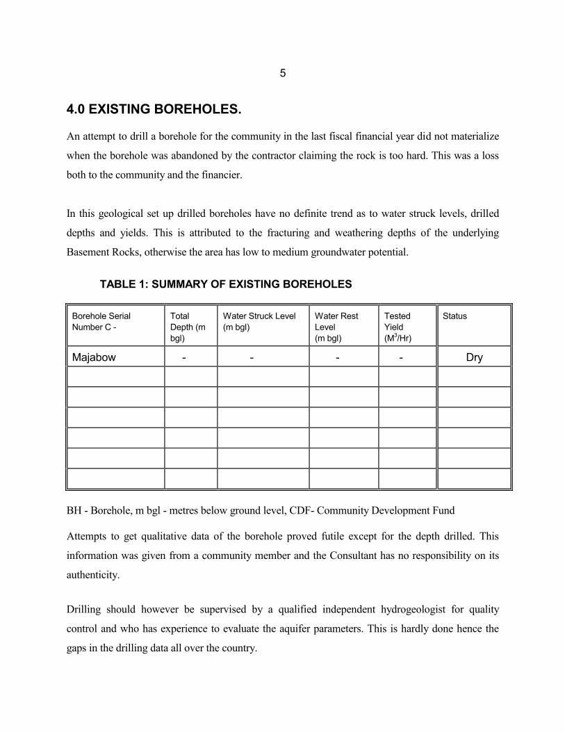
5
4.0 EXISTING BOREHOLES.
An attempt to drill a borehole for the community in the last fiscal financial year did not materialize
when the borehole was abandoned by the contractor claiming the rock is too hard. This was a loss
both to the community and the financier.
In this geological set up drilled boreholes have no definite trend as to water struck levels, drilled
depths and yields. This is attributed to the fracturing and weathering depths of the underlying
Basement Rocks, otherwise the area has low to medium groundwater potential.
TABLE 1: SUMMARY OF EXISTING BOREHOLES
Borehole SerialNumber C -
TotalDepth (mbgl)
Water Struck Level(m bgl)
Water RestLevel(m bgl)
TestedYield(M3/Hr)
Status
Majabow - - - - Dry
BH - Borehole, m bgl - metres below ground level, CDF- Community Development Fund
Attempts to get qualitative data of the borehole proved futile except for the depth drilled. This
information was given from a community member and the Consultant has no responsibility on its
authenticity.
Drilling should however be supervised by a qualified independent hydrogeologist for quality
control and who has experience to evaluate the aquifer parameters. This is hardly done hence the
gaps in the drilling data all over the country.
6
5.0 GEOPHYSICAL INVESTIGATIONS.
A great variety of geophysical methods are available to assist in the assessment of geological
subsurface conditions. In the present survey, the resistivity method (also known as the geo-electrical
method) and the Horizontal Electrical Profiling (HEP) methods has been used. The latter was used
to detect any anomalous conductive zones in the subsurface, which might be associated with faulted
or fractured zones.
Vertical Electrical Soundings (VES) were carried out to probe the conditions at such anomalous
zones within the sub-surface and to confirm the existence of groundwater. The VES probes the
resistivity layering below the site of measurement. The techniques are described below.
7.1 Basic Principles of the Resistivity Method
The electrical properties of the upper parts of the earth's crust are dependant upon the lithology,
porosity, the degree of pore space saturation and the salinity of the pore water. Saturated rocks have
lower resistivities than unsaturated and dry rocks. The higher the porosity of the saturated rock, the
lower its resistivity, and the higher the salinity of the saturating fluids, the lower the resistivity. The
presence of clays and conductive minerals also reduces the resistivity of the rock.
The resistivity of earth materials can be studied by measuring the electrical potential distribution
produced at the earth's surface by an electric current that is passed through the earth. The resistance
R of a certain material is directly proportional to its length L and cross-sectional area A, expressed
as: R = Rs *L/A (in Ohm) (1)
Where Rs is known as the specific resistivity, characteristic of the material and independent of its
shape or size. With Ohm's Law
R = dV/I (Ohm) (2)
Where dV is the potential difference across the resistor and I is the electric current through the
resistor; the specific resistivity may be determined by:
Rs = (A/L) *(dV/I) (in Ohm.m) (3)
7
5.2 General.
The field investigations carried out in the project area to evaluate the groundwater potential of this
area included the following:
- Geomorphological interpretation and hydrogeological reconnaissance to establish overview
impression of the area;
- Execution of geo-electrical measurements comprising the following:
- Horizontal Electrical Profiling using ABEM Terrameter SAS 300C;
- Vertical Electrical Sounding using the ABEM Terrameter SAS 300C.
5.3 Methods.
5.3.1 Horizontal Electrical Profiling (HEP).
These were carried out to determine changes in electrical properties laterally with a constant
electrode spacing and interpreted as a continuous profile. The electrode spacing controls both the
profiling depth and the resolution of the survey.
The probe depth on all the profiles was maintained at a depth of 50 metres with a constant interval
of 10 metres from one station to the other.
The observed resistivity values are plotted on logarithimic paper and the graph obtained depicts
lateral resistivity variation at constant depth. Geological structures such as faults, fractures, burried
stream channels that may conduct groundwater, can be inferred.
5.3.2 Vertical Electrical Soundings (VES).
Vertical Electrical Soundings were carried out to probe the electrical properties and depth to sub-
surface layered formations below the site of measurement at the most significant anomalous zones.
When carrying out a resistivity sounding, electric current is led into the ground by means of two
electrodes and the potential field generated by the current is measured.
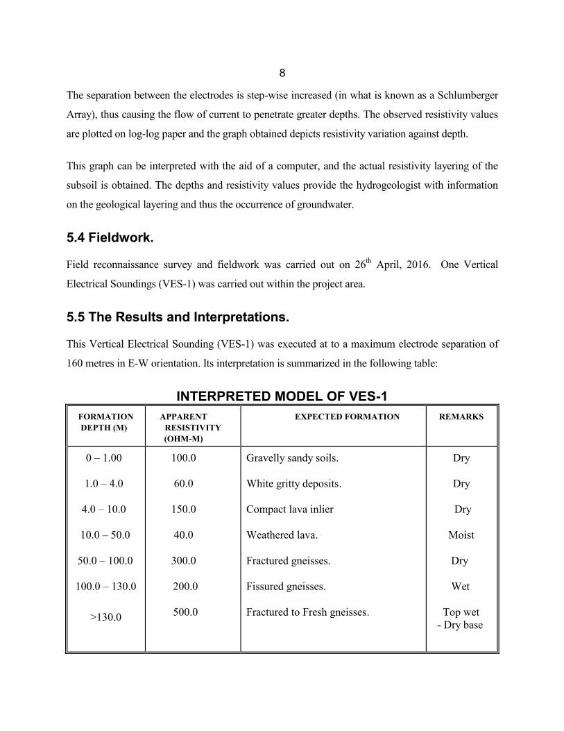
8
The separation between the electrodes is step-wise increased (in what is known as a Schlumberger
Array), thus causing the flow of current to penetrate greater depths. The observed resistivity values
are plotted on log-log paper and the graph obtained depicts resistivity variation against depth.
This graph can be interpreted with the aid of a computer, and the actual resistivity layering of the
subsoil is obtained. The depths and resistivity values provide the hydrogeologist with information
on the geological layering and thus the occurrence of groundwater.
5.4 Fieldwork.
Field reconnaissance survey and fieldwork was carried out on 26th April, 2016. One Vertical
Electrical Soundings (VES-1) was carried out within the project area.
5.5 The Results and Interpretations.
This Vertical Electrical Sounding (VES-1) was executed at to a maximum electrode separation of
160 metres in E-W orientation. Its interpretation is summarized in the following table:
INTERPRETED MODEL OF VES-1FORMATIONDEPTH (M)
APPARENTRESISTIVITY(OHM-M)
EXPECTED FORMATION REMARKS
0 – 1.00
1.0 – 4.0
4.0 – 10.0
10.0 – 50.0
50.0 – 100.0
100.0 – 130.0
>130.0
100.0
60.0
150.0
40.0
300.0
200.0
500.0
Gravelly sandy soils.
White gritty deposits.
Compact lava inlier
Weathered lava.
Fractured gneisses.
Fissured gneisses.
Fractured to Fresh gneisses.
Dry
Dry
Dry
Moist
Dry
Wet
Top wet- Dry base
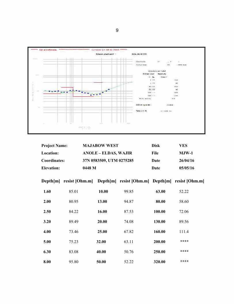
9
Project Name: MAJABOW WEST Disk VES
Location: ANOLE – ELDAS, WAJIR File MJW-1
Coordinates: 37N 0583509, UTM 0275285 Date 26/04/16
Elevation: 0448 M Date 05/05/16
Depth[m] resist [Ohm.m] Depth[m] resist [Ohm.m] Depth[m] resist [Ohm.m]
1.60 85.01 10.00 99.85 63.00 52.22
2.00 80.95 13.00 94.87 80.00 58.60
2.50 84.22 16.00 87.53 100.00 72.06
3.20 89.49 20.00 74.08 130.00 89.56
4.00 73.46 25.00 67.82 160.00 111.4
5.00 75.23 32.00 63.11 200.00 ****
6.30 83.08 40.00 50.76 250.00 ****
8.00 95.80 50.00 52.22 320.00 ****
10
6.0 CONCLUSION AND RECOMMENDATIONS.
On the basis of the foregoing discussion, it can be concluded that the project area is covered by
thin top soils. The top soils are underlain by weathered, fractured to fresh Rocks of the Basement
System mainly biotite hornblende gneisses, quartzites, granite gneisses, muscovite gneisses,
hornblende gneisses and qurtzo-feldspathic gneisses overlain by reddish brown gravelly sandy
soils in some areas.
From the existing borehole in the project area and in general it is expected to have low to
medium groundwater potential depending on the depth of weathering and fracturing zones of the
Basement rocks and the size of the catchment area.
All in all, it can be concluded that chances of striking enough quantity of water at the selected
borehole site is good taking into consideration that this site has fair groundwater recharge from
sizable catchment area.
On the basis of geological, hydrogeological and geophysical data it is recommended that a
borehole should be drilled at the selected site of VES-1. The proposed borehole should be drilled
to a depth of 100 metres minimum and 130 maximum below ground level.
The quality of groundwater is expected to be good though it might be slightly saline.
The proposed borehole should be lined with casings and screens of 152 mm minimum diameter
and should be gravel packed.
The proposed borehole should be installed with the following:-
1. Water master meter for monitoring groundwater abstraction.
2. Airline for monitoring water table fluctuation.
Finally drilling work should not commence until groundwater permits are obtained from Water
Resources Management Authority of Ministry of Water and Irrigation.
11
APPENDIX - Drilling
Drilling should be carried out at a diameter of not less than 8”, using either a rotary type machine.
The drilling rig should be able to drill to a depth of at least 160-m, at the specified diameter. The rig
and the drilling method adopted must be suitable for drilling through both unconsolidated material,
and hard, compact rocks. The rotary drilling technique offers very high penetration rates in all types
of materials, rig mobilisation and demobilisation are rapid, minimal casings are required during
drilling exercise and reliable yield estimates can easily be made during drilling.
Drilling additives to be used (e.g. foam or polymer) must be non-toxic and bio-degradable. In no
circumstances will bentonic additives considered to be acceptable, as they may plug the aquifer
zones and are extremely difficult to remove during development.
Percussion method will however considerably prolong the required time for drilling, which may be
undesirable if water is required at short notice. Another main disadvantage is that no reliable yield
estimates can be made during drilling. As a result, a reliable judgement whether to stop or continue
drilling at a certain depth can not be made. In addition, borehole development techniques will be
less efficient than with a rotary plant compressor. This may reduce the capacity of the borehole, and
may fail to stop the intake of fine sediments during pumping. In case of friable materials and/or
loose sediments, bentonite is used to stabilise the materials when drilling using percussion
technique. The sticky clay-based mud seals the aquifer pores reducing the aquifer transmissivity and
hence borehole yields. In rotary drilling, the biodegradable polymers or foam is used to stabilise
collapsing formations. This biodegradable mud can easily be removed during borehole
development.
On the other hand, the percussion method is considerably cheaper than the modern rotary technique,
partly because of the lower drilling rates, but also due to the often much lower sum charged for
mobilisation. However, it must be noted that the initial savings may be offset against the continuing
costs of labour, fuel, etc., the prolonged absence of a water source, and the time input of the Client
and his representatives. Regarding the long time required when applying the percussion drilling
technique.
12
Geological rock samples should be collected at 2 metre intervals. Water struck and rest levels
should be carefully recorded, as well as water quality and estimates of the yield of individual
aquifers encountered.
Great care should be taken that the water quality of the different aquifers is accurately determined.
Upon the first strike, drilling fluids should be effectively flushed, and after sufficient time, a water
sample should be taken of the air-blown (rotary) or bailed (percussion) yield. On-site analysis using
an EC meter, and preferably a portable laboratory, is recommended.
Well Design
The design of the well should ensure that screens are placed against the optimum aquifer zones. The
final design should be made by an experienced hydrogeologist.
Casing and Screens
The well should be cased and screened, in order to avoid collapsing and sediment intake.
Considering the moderate depth of the borehole, it is recommended to use Mild steel casings and
screens of 6" diameter. They should be machine cut not gas-slotted. Screen slots should be a
maximum of 1.5 mm in size. The minimum open area of the screens should be 5%.
Gravel Pack
The use of a gravel pack is recommended within the aquifer zone, because the aquifer could contain
sands or silts, which are finer than the screen slot size. An 8" diameter borehole screened at 6" will
leave an annular space of approximately 1", which is sufficient to allow the insertion of fine,
quartzitic gravel. The grain size of the gravel pack should be within the range of 2 to 5 mm, and
granules should be rounded to well rounded. Over 95% should be siliceous.
Gravel pack should be washed down with copious volumes of water to avoid bridging. The best
method, which is unfortunately rarely used, involves the insertion with a tremie pipe.
13
Well Construction
In installing screen and casing, centralizers at 6 metre intervals should be used to ensure centrality
within the borehole. This is particularly important to insert the artificial gravel pack all around the
screen. If installed, gravel packed sections should be sealed off at the top and bottom with clay or
bentonite seals (2 m). In this case, it is also recommended to install a 3 m long, cement grout plug at
the surface, to prevent contamination from entering the borehole.
The remaining annular space should be backfilled with inert material (drill cuttings may be used),
and the top five metres grouted with cement to ensure that no surface water at the well head can
enter the well bore and thus prevent contamination.
Well Development
Once screen, gravel pack, seals and backfill have been installed, the well should be developed.
Development is the term used to describe the procedures designed to maximize well yield.
Although an expensive element in the completion of a well, the additional costs are usually justified
by longer well life, greater efficiencies, lower operational and maintenance costs and a more
constant yield.
Development has two broad objectives, which can be divided into borehole and aquifer stimulation:
To repair the damage done to the aquifer material during drilling and restore the natural hydraulic
properties.
In both cable tool (i.e. percussion) and air hammer drilling, the bit action chips and crushes the
rock, and mixes it with water and other fine material into thick mud slurry. The pounding of the bit
forces this slurry into the openings in the wall of the borehole, thus blocking the pores and
impeding the flow of water from the aquifer. A thick "wall cake" may form, especially when clay
additives (such as bentonite) are used during drilling or where natural clays occur in the penetrated
formations. This cake, if not removed, may virtually plug the borehole, and significantly reduce the
discharge. It should be noted that the maximum yield of a formation can only be realized if all the
fractures and crevices are unblocked and able to supply water to the well.
14
Borehole development techniques are applied to break down and remove the impermeable layer of
clayey material from the borehole wall. Swabbing, wall-scratching, airlift raw hiding and
polyphosphate dosing are all borehole development techniques.
To alter the characteristics of the aquifer volume in the vicinity of the borehole, by improving
hydraulic contact between the aquifer and the hole. This is essentially aquifer development, and is
also known as aquifer stimulation.
Polyphosphate dosing, hydro fracturing and acidification are examples of aquifer stimulation
techniques. The development methods to be applied depend on the available equipment, and differ
significantly between percussion and rotary drilling (the latter being superior, when it comes to
efficiency):
Development with a percussion rig: if a cable tool rig has been deployed the available development
techniques are relatively simple, but less effective than the methods used in modern rotary drilling.
The following measures are recommended:
1Backwashing and bailing: using a surge block with rubber flaps slightly smaller than the internal
diameter of the hole, start near the top of the water bearing zones and surge downwards (surging
upwards may lead to the surge block sand-locking, which can jeopardize the hole). Bail the
borehole clean periodically. Repeat this cycle until no more material is brought up, bailed water is
clear and electrical conductivity is stable.
1Polyphosphate dosing: percussion equipment does not include mudpumps and drillpipe, so jetting
is impossible. Polyphosphate dosing comprises no more than simply pouring water with dissolved
sodium hexametaphosphate and calcium hypochlorite into a pipe, the base of which is located near
the bottom of the hole.
Recommended concentrations are 3.8 kg/m3 of sodium hexametaphosphate (a locally available,
common food additive and clay disaggregant known under the trade names “Calgon” or “SHMP”),
and 1.5 kg/m3 of calcium hypochlorite. The polyphosphate is allowed to act for 12 hours or
overnight.
15
Repeat the backwashing and bailing cycle until the water is clear and electrical conductivity stable.
If a rotary rig equipped with a strong air compressor is available, more effective developmenttechniques can be applied:
Airlift rawhiding, into and through the aquifer zones. This should continue until the water lifted is
clean and clear, with electrical conductivity stable. Rawhiding comprises cyclic airlifting: once the
airlift has been established, air supply is cut off and water allowed to cascade down the hole. This
creates overpressures across the borehole wall, which agitates the formation and enhances cleaning.
The airlift is then started again and the cycle repeated.
Water jetting with an on-wall velocity of 30 m/s: at least 0.3 m3 of fluid should be jetted per linear
metre of screen. The water used for jetting must be absolutely clean, and it is dissolved as in the
polyphosphate dosing described under Section 4.2. The jetting tool should be so constructed that
the jet openings are not more than 1" (25 mm) from the borehole wall. Jetting should start from the
top of the water bearing formation rotating downwards. After the entire saturated zone has been
jetted, the hole should be left for at least 12 hours or overnight, to allow the hexametaphosphate to
work on the “wall cake” and any clayey material in the aquifer material.
Airlift raw hiding again, from the bottom of the hole, until airlifted water is absolutely clean and
electrical conductivity. During development, an estimate of the bailed or air-blown yield should be
made. This usually gives a fair indication of the final range of abstraction that can be expected from
the borehole. The use of over pumping as a means of development is not advocated, since it only
increases permeability in zones, which are already permeable.
Well Testing
After development and preliminary tests, a step-drawdown test and a 24-hour long-duration well
test at constant discharge rate should be carried out. Well tests have to be performed on all newly-
completed wells: apart from providing information on the quality of drilling, design and
development, it also enables the hydrogeologist to compute sustainable abstraction rates, design
drawdown, and other important well and aquifer parameters.
16
During the test, the well is pumped from a measured static water level (SWL) at a known yield.
Simultaneously, the discharge rate and the pumped water level (PWL) as a function of time are
recorded. After stopping the pump, recovery is measured until the water level has returned within
5% of the original level, in comparison with the total pumped drawdown.
The specific capacity and the efficiency of a borehole are determined during a step-drawdown test.
Simultaneously, target yields for the constant discharge test can be set. The step-drawdown test
usually comprises 4 to 6 steps of 60 to 90 minutes each. The pumping rates are increased step-by-
step, e.g. by gradually opening a gate valve. Recovery may be measured after the last step, but this
is not really necessary if a constant discharge test is conducted as well. However, before starting the
constant discharge test, 95% of the pumped drawdown must be recovered, or, alternatively, no
increase in level must be observed for a period of more than 4 hours.
The constant discharge test allows calculation of specific aquifer parameters, such as transmissivity,
hydraulic conductivity and storage coefficient. In addition, the sustainable volume of abstraction,
the design drawdown and the final pump specification and setting can be determined. The
minimum duration of the test should be 24 hours, followed by 12 hours of recovery observations, or
alternatively until 95% of the total drawdown has been regained.
Legal Requirements
It is a legislated condition imposed by the Water and Irrigation and Water Act 2002, that all
boreholes in Kenya be equipped with a master/flow meter and a means by which water levels can
be measured. These measures have been designed to allow the collection of data, which will enable
both the authorities and the borehole operators to learn more about the reliability and limitations of
their groundwater resources.
The easiest method of water level monitoring is through a narrow (1.25” to 2”) dipper line which is
installed along the rising main. An electric dipper should be used to measure water levels directly,
with an accuracy of approximately 1 cm. An electrical dipper should also be equipped in the
borehole to monitor water rest level.
17
Pumping Plant
Several options are open to the Client:
a) Submersible pumps:
Currently, these are arguably the most popular borehole pumps in Kenya. Electrical submersibles
are efficient and require little maintenance, though of course they do require electrical power on
site, e.g. from a generator set.
b) Electrical solar submersible pumps:
These are not widely used mainly because the plant is comparatively expensive. Generally, solar
pumps are not routinely stocked by the main pump suppliers.
c) Turbine or Mono pumps:
Given the yield requirements of the Client, both turbine and Mono-type pumps would be needlessly
expensive.
d) Reciprocating pumps:
Formerly the most popular type of pump used in Kenya. With the introduction of electrical
submersibles and modern windpumps, reciprocating pumps. They have gradually fallen out of
favour. However, when it comes to simplicity and robustness, coupled with a wide range of power
plant (almost any suitable diesel driving belt), there is little to beat a reciprocating pump.
e) Solar Submersibles pumps:
Solar submersible pumps have come up in the market as the most economical in running costs for
its natural resource. However, the initial installation cost is high, it promotes green energy and is
most recommended where there is no electricity.
To avoid sediment ingress, and ensure a long lifespan of both the borehole and the pumping unit,
the permanent pump should be installed at least 2 m above, and certainly not within, the screened
section.