Embed Size (px)
Citation preview

En
glis
h
Elcometer Protovale 331
Concrete Covermeter
Model B
Operating Instructions

En
glis
hR
The Elcometer Protovale 331 Concrete Covermeter has been tested inaccordance with EU regulations governing Electro-magneticcompliance and it meets the required directives.
Note: Readings may be affected if the unit is operated within a radio frequencyelectromagnetic strength of greater than 3 V/m.
, CoverMaster® and are registered trademarks ofElcometer Instruments Ltd.
All other trademarks acknowledged.© Copyright Elcometer Instruments Ltd. 2005.
All rights reserved. No part of this Document may be reproduced, transmitted,transcribed, stored (in a retrieval system or otherwise) or translated into anylanguage, in any form or by any means (electronic, mechanical, magnetic,optical, manual or otherwise) without the prior written permission ofElcometer Instruments Ltd.
Doc.No. TMA-0312 Issue 01Text with Cover No: 19344

CONTENTS
R
CONTENTSSection Page
1 About your Covermeter. . . . . . . . . . . . . . . . . . . . . . . . . . . . . . . . . . . 1
2 Quick-start . . . . . . . . . . . . . . . . . . . . . . . . . . . . . . . . . . . . . . . . . . . . . 4
3 Getting started . . . . . . . . . . . . . . . . . . . . . . . . . . . . . . . . . . . . . . . . . . 43.1 The power supply. . . . . . . . . . . . . . . . . . . . . . . . . . . . . . . . . . . . . . . . . 43.2 Fitting search heads. . . . . . . . . . . . . . . . . . . . . . . . . . . . . . . . . . . . . . . 63.3 The controls . . . . . . . . . . . . . . . . . . . . . . . . . . . . . . . . . . . . . . . . . . . . . 73.4 Switching the Covermeter on and off . . . . . . . . . . . . . . . . . . . . . . . . . 103.5 The display. . . . . . . . . . . . . . . . . . . . . . . . . . . . . . . . . . . . . . . . . . . . . 103.6 Selecting a language . . . . . . . . . . . . . . . . . . . . . . . . . . . . . . . . . . . . . 123.7 Computer interface . . . . . . . . . . . . . . . . . . . . . . . . . . . . . . . . . . . . . . 123.8 Using the earphone . . . . . . . . . . . . . . . . . . . . . . . . . . . . . . . . . . . . . . 133.9 Zeroing the Covermeter . . . . . . . . . . . . . . . . . . . . . . . . . . . . . . . . . . . 13
4 The menus . . . . . . . . . . . . . . . . . . . . . . . . . . . . . . . . . . . . . . . . . . . . 14
5 Locating reinforcement bars . . . . . . . . . . . . . . . . . . . . . . . . . . . . . 165.1 Before you start . . . . . . . . . . . . . . . . . . . . . . . . . . . . . . . . . . . . . . . . . 165.2 To locate a single layer of reinforcement bars . . . . . . . . . . . . . . . . . . 165.3 To locate two layers of reinforcement bars . . . . . . . . . . . . . . . . . . . . 175.4 To determine the orientation of a reinforcement bar . . . . . . . . . . . . . 195.5 Practice . . . . . . . . . . . . . . . . . . . . . . . . . . . . . . . . . . . . . . . . . . . . . . . 195.6 Surface mapping . . . . . . . . . . . . . . . . . . . . . . . . . . . . . . . . . . . . . . . . 20
6 Measuring depth of cover . . . . . . . . . . . . . . . . . . . . . . . . . . . . . . . . 216.1 Before you start . . . . . . . . . . . . . . . . . . . . . . . . . . . . . . . . . . . . . . . . . 216.2 Procedure . . . . . . . . . . . . . . . . . . . . . . . . . . . . . . . . . . . . . . . . . . . . . 216.3 Accuracy . . . . . . . . . . . . . . . . . . . . . . . . . . . . . . . . . . . . . . . . . . . . . . 22

CONTENTS
R
7 Selecting a bar size . . . . . . . . . . . . . . . . . . . . . . . . . . . . . . . . . . . . . 23
8 Adjusting sensitivity . . . . . . . . . . . . . . . . . . . . . . . . . . . . . . . . . . . . 24
9 Measuring welded mesh and joined bars . . . . . . . . . . . . . . . . . . . 25
10 Search heads . . . . . . . . . . . . . . . . . . . . . . . . . . . . . . . . . . . . . . . . . . 27
11 Error messages . . . . . . . . . . . . . . . . . . . . . . . . . . . . . . . . . . . . . . . . 30
12 Personalised welcome screen . . . . . . . . . . . . . . . . . . . . . . . . . . . . 31
13 Storage . . . . . . . . . . . . . . . . . . . . . . . . . . . . . . . . . . . . . . . . . . . . . . . 32
14 Maintenance . . . . . . . . . . . . . . . . . . . . . . . . . . . . . . . . . . . . . . . . . . . 32
15 Upgrading your Covermeter . . . . . . . . . . . . . . . . . . . . . . . . . . . . . . 32
16 Related equipment. . . . . . . . . . . . . . . . . . . . . . . . . . . . . . . . . . . . . . 33
17 Technical data . . . . . . . . . . . . . . . . . . . . . . . . . . . . . . . . . . . . . . . . . 34
18 Accessories . . . . . . . . . . . . . . . . . . . . . . . . . . . . . . . . . . . . . . . . . . . 36
19 Index . . . . . . . . . . . . . . . . . . . . . . . . . . . . . . . . . . . . . . . . . . . . . . . . . 37

ABOUT YOUR COVERMETER
R
hank you for your purchase of this Elcometer Protovale 331 Model BConcrete Covermeter. Welcome to Elcometer.
Elcometer are world leaders in the design, manufacture and supply ofinspection equipment for concrete and coatings.Our concrete inspection products include a comprehensive range of concrete,and civil engineering inspection equipment. Our coatings products cover allaspects of coating inspection, from development through application to postapplication inspection.The Elcometer Protovale 331 Model B Concrete Covermeter is a world beatingproduct. With the purchase of this Covermeter you now have access to theworldwide service and support network of Elcometer. For more information visitour website at www.elcometer.com
1 ABOUT YOUR COVERMETER
The Elcometer Protovale 331 Model B Concrete Covermeter is a handheldCovermeter for fast and accurate location, orientation and measurement ofconcrete reinforcement bars.
Locate • Identify orientation • Measure depth of cover
The Covermeter is available in three versions; Model B (entry level), Model S(intermediate level) and Model T (data logging). This manual describes theoperation of the Elcometer Protovale 331 Model B.All versions of the Covermeter feature an easy-to-use menu-driven graphicalinterface which guides the user during setup of the Covermeter and duringmeasurement.A range of fully interchangeable search heads is available to suit yourrequirements. Search heads include a keypad which allows remote operationof the Covermeter. See “Search heads” on page 27 for full details.
To maximise the benefits of your new Elcometer Protovale 331 ConcreteCovermeter please take some time to read these Operating Instructions.Do not hesitate to contact Elcometer or your Elcometer supplier if youhave any questions.
T
1

ABOUT YOUR COVERMETER
R
1.1 Features• Menu-driven backlit graphical user interface• 3 sizes of search head + borehole probe• Weather proof to IP65• International standard bar size database in memory• Multiple languages• UpgradeableIf you require more advanced features such as statistics or memory forreadings, Elcometer Protovale 331 models ‘S’ and ‘T’ provide this facility. YourElcometer Protovale 331 model ‘B’ can be upgraded to a model ‘S’ or ‘T’ - see“Upgrading your Covermeter” on page 32. Contact Elcometer or your localElcometer supplier for more details.
1.2 What this box contains• Elcometer Protovale 331 Model B Concrete Covermeter• Standard search head• Search head connecting cable• Rechargeable battery pack and battery charger• Earphone• Shoulder strap• Plastic carrying case• Operating instructions
2

ABOUT YOUR COVERMETER
R
Figure 1. Elcometer Protovale 331 Model B Concrete Covermeter
1.3 StandardsThe Elcometer Protovale 331 Model B Concrete Covermeter can be used inaccordance with the following National and International Standards:ACI 318 BS1881:204 CP 110DIN 1045 EC2 SIA 162
1.4 Conventions in these instructionsA simple menu structure helps you get the most from your Covermeter - see“The menus” on page 14. There are many references to this menu structure inthese instructions. As an example, the LANGUAGE option which is in SETUP from the MAINMENU would be shown in these instructions as:
MENU / SETUP / LANGUAGEThese instructions include images of Elcometer Protovale 331 screens withunits set to millimetres (mm). Similar screens will be seen when the Covermeteris set to inches.
3

QUICK-START
R
2 QUICK-START
To configure the Covermeter quickly and start taking readings:1. Charge the batteries. . . . . . . . . . . . see page 42. Fit search head . . . . . . . . . . . . . . . see page 63. Switch on . . . . . . . . . . . . . . . . . . . . see page 104. Select language . . . . . . . . . . . . . . . see page 125. Zero the Covermeter . . . . . . . . . . . see page 136. To locate a bar . . . . . . . . . . . . . . . . see page 167. To measure depth of a bar . . . . . . . see page 21For an overview of your Covermeter menus and functions, see pages 14 to 15.
3 GETTING STARTED
This section of the instructions is intended for first-time users of the Covermeter.It contains essential information about batteries, assembling the Covermeter,the controls and the display. At the end of this section you will be ready to takereadings.
3.1 The power supplyYour Covermeter is powered by a rechargeable Lithium-Iona battery pack whichcan be charged inside or outside the Covermeter.One battery pack is supplied with the Covermeter. To increase productivity onsite, Elcometer recommends that you purchase a spare battery pack which canbe charged while you are using your Covermeter. To order an additional batterypack (see “Accessories” on page 36), contact Elcometer or your localElcometer supplier.
Charging the batteriesThe rechargeable battery must be fully charged before using the Covermeter forthe first time. Use the charger supplied with your Covermeter to charge thebattery; use of any other type of charger is a potential hazard, may damage yourCovermeter and will invalidate the warranty. Do not attempt to charge any otherbatteries with the supplied charger.Always charge the battery indoors. To prevent overheating, ensure that thecharger is not covered.
a. The Covermeter is not designed to operate using dry cell batteries.
4
GETTING STARTED
R
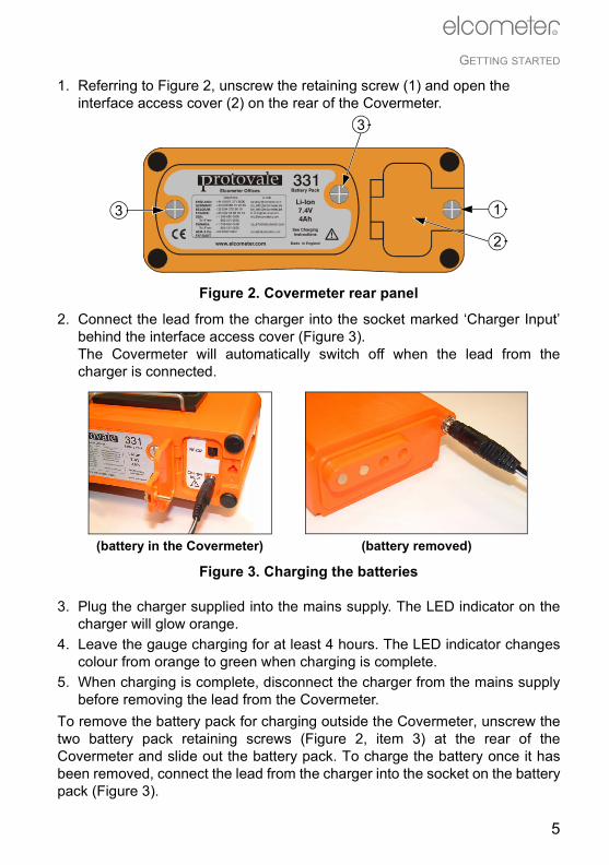
1. Referring to Figure 2, unscrew the retaining screw (1) and open the interface access cover (2) on the rear of the Covermeter.
Figure 2. Covermeter rear panel
2. Connect the lead from the charger into the socket marked ‘Charger Input’behind the interface access cover (Figure 3).The Covermeter will automatically switch off when the lead from thecharger is connected.
Figure 3. Charging the batteries
3. Plug the charger supplied into the mains supply. The LED indicator on thecharger will glow orange.
4. Leave the gauge charging for at least 4 hours. The LED indicator changescolour from orange to green when charging is complete.
5. When charging is complete, disconnect the charger from the mains supplybefore removing the lead from the Covermeter.
To remove the battery pack for charging outside the Covermeter, unscrew thetwo battery pack retaining screws (Figure 2, item 3) at the rear of theCovermeter and slide out the battery pack. To charge the battery once it hasbeen removed, connect the lead from the charger into the socket on the batterypack (Figure 3).
331
Made In Englandwww.elcometer.com
Li-Ion7.4V4Ah
Battery Pack
See ChargingInstructions
Elcometer Offices
!
1
2
3
3
(battery in the Covermeter) (battery removed)
5

GETTING STARTED
R
Do not allow metallic objects to come into contact with the batteryterminals; this may cause a short circuit and result in permanentdamage to the battery.
Battery condition indicatorThe state of charge of the battery is shown by a symbol on the display:
3.2 Fitting search headsThe Covermeter must be switched off when search heads are fitted orremoved.Connect the search head to the Covermeter using the supplied connectingcable. The connecting cable is fitted with a metal screw-type connector at eachend. To fit a connector, align the keyway, push the connector into place andthen tighten the metal collar.A range of search heads is available for your Covermeter - see “Search heads”on page 27 for full details. The search head icon on the reading screenindicates the type of search head connected to the Covermeter:
Narrow pitch
Standard
Deep cover
Borehole probe - set to forward-looking operation
Borehole probe - set to sideways-looking operation
Symbol Battery charge/action required
70% to 100%
40% to 70%
20% to 40%
10% to 20%, charging recommended
<10%, Covermeter beeps every 10 seconds and symbol flashes - immediate charging required
5 loud beeps, Covermeter switches off automatically
6

GETTING STARTED
R
The Covermeter must be zeroed after a search head has been fitted - thedisplay will show PLEASE ZERO and the ZERO softkey will flash to remind you.The metal and plastic bracket on the outside of the main unit is a storage clipfor standard and narrow pitch search heads. The bracket provides a convenientplace to store the search head while the Covermeter is not in use.
Figure 4. Search head storage clip
3.3 The controlsAll functions of the Covermeter can be controlled using the keypad on the mainunit. There are two types of keys on the keypad; fixed function keys and ‘soft’keys (Figure 5).
Figure 5. Elcometer Protovale 331 Concrete Covermeter main keypad
ALL DIMENSIONS IN m.m.MenuEsc
R
Fixed function keys
‘Soft’ keys
7

GETTING STARTED
R
Fixed function keys
SoftkeysThese are the four keys located immediately below the display.
Key Name FunctionsScrollUp
Scrolls up through menus and lists of valuesIncreases sensitivity
Scroll Down
Scrolls down through menus and lists of valuesDecreases sensitivity
Menu/Esc
Accesses menusEscapes from menusDiscards values entered on display
On/Off Switches the Covermeter on or off
Enter Selects menu itemsToggles tick boxes on/offConfirms values entered on display
The function of these keys varies and is defined by symbols and text on the screen
MenuEsc
8

GETTING STARTED
R
Search head keypadThe search head is fitted with a keypad which mimicsthe functions of some of the keys on the main unit.Use the keys on the search head in the same way asyou use the keys on the main unit.The function of the Enter and Menu/Esc keysis identical to the corresponding keys on the main unit.The function of the Scroll Up/ZERO and ScrollDown/SIZE keys depends upon whether thereading screen is displayed or not.
Key Name FunctionsScrollUp/ZERO
Zeros the Covermeter (only when the display shows the reading screen)Scrolls up through menus and lists of valuesIncreases numerical values
Scroll Down/SIZE
Bar size selection (only when the display shows the reading screen)Scrolls down through menus and lists of valuesDecreases numerical values
Enter Selects menu itemsToggles tick boxes on/offConfirms values entered on display
Menu/Esc
Accesses menusEscapes from menusDiscards values entered on display
MenuEsc
0
R
Figure 6. Search head keypad
MenuEsc
0
0
MenuEsc
9

GETTING STARTED
R
3.4 Switching the Covermeter on and offNote: Before switching the Covermeter on for the first time read “Selecting alanguage” on page 12.To switch the Covermeter on, press .To switch the Covermeter off, press and hold for two seconds. TheCovermeter will beep, two single tones followed by a double tone, and will thenswitch off.The Covermeter includes an automatic switch off feature which will help toextend the battery life (time between charges). The automatic switch off timecan be set to OFF, 5, 6, 7, 8, 9 or 10 minutes.
MENU / SETUP / AUTO SWITCH OFFA countdown timer is displayed on the screen 60 seconds before theCovermeter automatically switches off. The timer counts down from 60 to 0 towarn you that the Covermeter is about to switch off. Press any key while thecountdown timer is displayed to cancel automatic switch off.
3.5 The displayTake some time to familiarise yourself with the information displayed on thescreen of your Covermeter. The screen shows:• Welcome information• Measurement information• Menus to configure the Covermeter and control functions• Help and miscellaneous informationWhen the Covermeter is switched on an opening (welcome) informationscreenb may be displayed briefly before the main reading screen appears.The information displayed depends upon whether you are takingmeasurements, reviewing readings or setting up the Covermeter.
b. The opening (welcome) screen can be disabled.
MENU / SETUP / OPENING SCREEN.Customised welcome screens can be created on a PC and downloaded into thegauge - see “Personalised welcome screen” on page 31.
10

GETTING STARTED
R
The main screen displayed (while you are taking measurements) is the ReadingScreen. The components of the reading screen are described below:
Refer to page numbers in brackets ( ) for more information.
SymbolsA wide range of symbols is used on the display. The meaning of all thesesymbols is stored in the Covermeter.
MENU / ABOUT / HELP
LCD contrastAdjust the contrast of the display to suit lighting conditions.
MENU / SETUP / LCD CONTRAST
Signal strength indicator bar (16) Battery condition indicator (6)
Bar size/number (23) Depth of cover (21)
Sensitivity (24) Search head type (6)
Softkey function indicators (8)
11

GETTING STARTED
R
BacklightThe display includes a backlight which illuminates the display for 10 secondsafter any key is pressed and during measurements. Switch the backlight on oroff as required. Switching the backlight off will increase battery life.
MENU / BACKLIGHT
3.6 Selecting a languageYour Covermeter has a number of built-inlanguages. When the Covermeter is switchedon for the first time after dispatch from theElcometer factory the display will show thelanguage selection screen (Figure 7).
At first switch on
1. Press or to locate language required.
2. Press to activate the selected language.The Covermeter operates in the new language until changed.
At any time1. Switch Covermeter off.2. Press and hold left hand softkey.3. Press to switch on Covermeter.
The display will show the language selection screen with the currentlanguage highlighted by the cursor.
4. Release left hand softkey.5. Press or to locate language required.6. Press to activate the selected language.Alternatively, select a language at any time.
MENU / SETUP / LANGUAGE
3.7 Computer interfaceYour Covermeter is fitted with an RS232 interface. The interface is locatedunder the interface access cover at the rear of the Covermeter - see Figure 2and Figure 3 on page 5.
Figure 7. Language selection screen
12

GETTING STARTED
R
This 5-pin RS232 interface is used with an optional data transfer cable (see“Accessories” on page 36) to connect the Covermeter to the RS232 portc of acomputer. When the Covermeter is connected to a computer you can:• Download personalised screens to the Covermeter (see “Personalised
welcome screen” on page 31).
3.8 Using the earphoneTo use the earphone, plug the connector into the 3.5 mm socket marked onthe front of the Covermeter. Replacement earphones are available as anoptional accessory - see “Accessories” on page 36.
3.9 Zeroing the CovermeterThis action is requested by the Covermeter whenever it is switched on, andperiodically thereafter (at least once every 10 minutes). The user can optionallyzero the instrument at any time.If zeroing is required, the cover display is blanked, the user is prompted, and nofurther readings can be entered until zeroing is completed.To zero the Covermeter, hold the search head in the air well away from anymetal and press the ZERO softkey. Zeroing is complete when the ZERO softkeyindicator stops flashing. Sometimes more than one press of the ZERO softkeywill be required; this is quite normal.
c. An RS232 to USB transfer cable is available which allows you to connect yourCovermeter to a USB port on your computer. See “Accessories” on page 36 forordering details.
13

THE MENUS
R
4 THE MENUS
To access the menus press the MENU softkey. To return to the reading screenquickly, press and hold the MENU softkey.
4.1 MENUBACKLIGHT . . . . . . . . . . .Toggles the display backlight on or offSETUP. . . . . . . . . . . . . . . .Opens Setup menu . . . . . . . . . See 4.2 SETUP ABOUT . . . . . . . . . . . . . . .Opens About menu . . . . . . . . . See 4.3 ABOUT RESET. . . . . . . . . . . . . . . .Opens Reset menu . . . . . . . . . See 4.4 RESET Note: When Backlight is on, the display is illuminated for approximately 10 seconds afterany key is pressed and during measurements.
MENUBACKLIGHT SETUP ABOUT RESET
SETUPUNITSBEEP VOLUME 3LANGUAGEAUTO SWITCH OFF 5OPENING SCREENLCD CONTRAST
ABOUTGAUGE INFORMATIONPROBE INFORMATIONCONTACTHELP
RESETINTL GAUGEUSA GAUGE
14

THE MENUS
R
4.2 SETUPUNITS . . . . . . . . . . . . . . . .Use Scroll keys to select measurement units (mm/inch)
and then press EnterBEEP VOLUME. . . . . . . . .Use Scroll keys to select beep volume 0 (off) to 5 (maximum)
and then press EnterLANGUAGE. . . . . . . . . . . .Use Scroll keys to select menu language and then press
enterAUTO SWITCH OFF . . . . .Use Scroll keys to select auto switch off time, 5 to 10 minutes
or off and then press EnterOPENING SCREEN . . . . .Press Enter to toggle the opening screen on or offLCD CONTRAST. . . . . . . .Use Scroll keys to select LCD contrast, 0 to 8
and then press Enter
4.3 ABOUTGAUGE INFORMATION . .Press Enter to display technical information about the
CovermeterPROBE INFORMATION . .Press Enter to display technical information about the search
headCONTACT . . . . . . . . . . . . .Press Enter to display Elcometer offices worldwide and
(if programmed) Supplier contact detailsHELP . . . . . . . . . . . . . . . . .Press Enter to display an explanation of all the symbols
used on the display
4.4 RESETINTL GAUGE. . . . . . . . . . .Press Enter to Reset Covermeter to International settingsd
(DD/MM/YYYY date format, metric units, etc.)USA GAUGE . . . . . . . . . . .Press Enter to Reset Covermeter to USA settingse
(MM/DD/YYYY date format, imperial units, etc.)Note: The Covermeter will display a Yes/No confirmation screen before reset isactivated.
d. International settings can also be activated at switch on:Press and hold third softkey and switch on gauge.
e. USA settings can also be activated at switch on:Press and hold fourth softkey and switch on gauge.
15

LOCATING REINFORCEMENT BARS
R
5 LOCATING REINFORCEMENT BARS
This section describes how to set up and use your Covermeter to locatereinforcement bars.
5.1 Before you start• Are you using the correct search head?
See “Search heads” on page 27.
5.2 To locate a single layer of reinforcement bars1. Connect the search head to the Covermeter.2. Switch on the Covermeter.3. Zero the Covermeter.4. Adjust sensitivity - see “Adjusting sensitivity” on page 24.5. Align the search head parallel to the reinforcement bars being sought.6. Maintain the alignment of the search head and move the search head
across the search area (Figure 8).
Figure 8. Align search head and scan across bars
MenuEsc
0
R
MenuEsc
0
R
16

LOCATING REINFORCEMENT BARS
R
When the search head is approaching a reinforcement bar:• The Covermeter will start to emit a sound which will increase in pitch as
the search head moves closer to the bar.• The signal strength indicator bar on the display will increase in length.• The depth of cover on the display will show a number.• The LED on the search head will start to glow.The search head is aligned directly over a reinforcement bar when:• The pitch of the sound is at its highest.• The signal strength indicator bar is at its maximum.• The depth of cover is at its minimum.• The LED is glowing at its most intense.
7. Record the position of the reinforcement bar (using chalk or similar).
5.3 To locate two layers of reinforcement barsLayers of reinforcement bars are typically orientated at right angles to eachother. To locate individual layers of reinforcement bars, carry out the procedurein section 5.2 for each layer.
If the bars in the two layers are of similar size (Figure 9):Search for the nearer layer first; it gives a stronger signal, and is least influencedby the other bars. Then search for the second layer, this time scanning the headin lanes between the previously located positions of the first layer of bars.• The first scan locates the nearer (top) layer.• The second scan locates the second (bottom) layer.
Figure 9. Scanning layers of bars of equal size
Second scan
First scan
17

LOCATING REINFORCEMENT BARS
R
If the bars in the nearer layer are thin compared with those in the deeper layer (Figure 10):Search for the deeper layer first; it gives a stronger signal, and is leastinfluenced by the other bars. Then search for the nearer layer, this timescanning the head in lanes between the now-known positions of the deeperlayer of bars.• The first scan locates the second (bottom) layer.• The second scan locates the nearer (top) layer.
Figure 10. Scanning layers of bars of different size
(This situation is typical of a nearer layer consisting of relatively thin tie-wires orstirrups, and the deeper layer consisting of much larger main structural bars.)
First scan
Second scan
18

LOCATING REINFORCEMENT BARS
R
5.4 To determine the orientation of a reinforcement bar1. Locate the position of the reinforcement bar - see “To locate a single layer
of reinforcement bars” on page 16.2. Hold the search head over the bar. Move the search head side-to-side and
rotate the head clockwise/anti-clockwise until the signal is at a maximum(Figure 11).When the signal is at its maximum, the search head is aligned parallel withthe reinforcement bar.
Figure 11. Determining orientation of a reinforcement bar
5.5 PracticeBecause your Covermeter is unaffected by the nature of the material coveringthe reinforcing bars, the easiest way to practice location and orientationtechnique is to use uncovered bars which you can see. A block of wood orplastic 20 mm to 45 mm thick can be held between the search head and thebars to simulate the depth of concrete cover.Start from the simplest situation, a single straight bar, and progress throughparallel bars, lapped bars, and crossing bars. As you develop skill andconfidence with uncovered bars, move on to locating bars in more realisticsituations.
MenuEsc
0
R
19
LOCATING REINFORCEMENT BARS
R
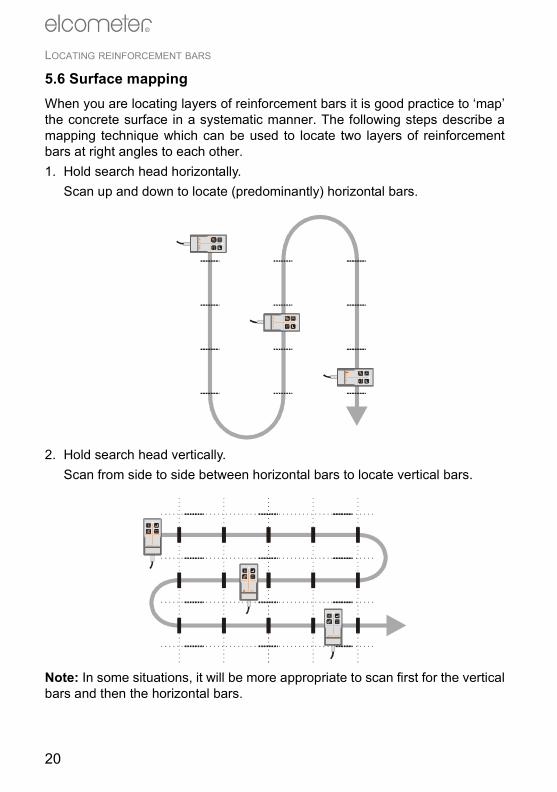
5.6 Surface mappingWhen you are locating layers of reinforcement bars it is good practice to ‘map’the concrete surface in a systematic manner. The following steps describe amapping technique which can be used to locate two layers of reinforcementbars at right angles to each other.1. Hold search head horizontally.
Scan up and down to locate (predominantly) horizontal bars.
2. Hold search head vertically.Scan from side to side between horizontal bars to locate vertical bars.
Note: In some situations, it will be more appropriate to scan first for the verticalbars and then the horizontal bars.
Menu
Esc
0
R
Menu
Esc
0
R
Menu
Esc
0
R
MenuEsc
0
R
MenuEsc
0
R
MenuEsc
0
R
20

MEASURING DEPTH OF COVER
R
6 MEASURING DEPTH OF COVER
This section describes how to set up and use your Covermeter to measure thedepth of cover over reinforcement bars.
6.1 Before you start• Are you using the correct search head?
See “Search heads” on page 27.
• What units of measurement do you want to use?See “SETUP” on page 15.
6.2 Procedure1. Connect the search head to the Covermeter.2. Switch on the Covermeter.3. Zero the Covermeter.4. Select bar diameter - see “Selecting a bar size” on page 23.5. Adjust sensitivity - see “Adjusting sensitivity” on page 24.6. Locate the reinforcement bar using the sound, the LED and the display as
indicators.7. The reading of cover is continuously updated on the display in large digits.
If you are satisfied that the search head is directly over the reinforcementbar, record the depth of cover reading and move on to the next bar.
21

MEASURING DEPTH OF COVER
R
6.3 AccuracyThe reading of cover will only be accurate if all the following conditions aresatisfied:• The instrument has been zeroed.• The search head is over the centre-line of the bar.• The search head is parallel to the bar.• The search head is not over, or near, any other bars which might affect the
readingf.If the reinforcement bar is too deep to measure successfully (over-range), thedepth of cover will be displayed as infinite (Figure 12).
Figure 12. Depth of cover over-range (infinite)
f. If reinforcement bars are too close together to measure with the standard searchhead, try using the narrow pitch search head. See “Accessories” on page 36 forordering details.
22

SELECTING A BAR SIZE
R
7 SELECTING A BAR SIZE
The dimensions of reinforcement bars are stored within the Covermeter. Thedimensions are grouped into four standard series; Metric, Imperial, ASTM/Canadian and Japanese.To select a bar size, display the reading screen and press the BAR softkey toaccess Bar Size selection. Press the SERIES softkey to select the appropriateseries and then use or to adjust the bar size. Press to accept thebar size and return to the Reading Screen.
The bar sizing functions of the Covermeter will display any measured bar sizeto the nearest size in the selected series.
Metric Imperial ASTM/Canadian Japanese
Bar size
Diam.(mm)
Bar size
Diam.(inch)
Bar size
Area(mm2)
Bar size
Diam(mm)
5 5 #2 0.250 10M 100 6 65.5 5.5 #3 0.375 15M 200 9 96 6 #4 0.500 20M 300 10 107 7 #5 0.625 25M 500 13 138 8 #6 0.750 30M 700 16 169 9 #7 0.875 35M 1000 19 1910 10 #8 1.000 45M 1500 22 2211 11 #9 1.125 55M 2500 25 2512 12 #10 1.250 29 2914 14 #11 1.375 32 3216 16 #12 1.500 35 3518 18 #13 1.625 38 3820 20 #14 1.750 41 4122 22 #15 1.875 44 4425 25 #16 2.000 48 4828 28 #18 2.250 51 5132 32 57 5736 3640 4044 4450 50
23

ADJUSTING SENSITIVITY
R
8 ADJUSTING SENSITIVITY
The sensitivity setting is indicated by the variable wedge-shaped symbol on the display. To increase the sensitivity,press . To decrease the sensitivity, press .Typically, set the sensitivity to produce a slow ‘clicking’ soundin the absence of metal. With the sensitivity set at this level you will be able todifferentiate quickly between bars of the same size located at different depths.If the sensitivity is optimised, the pitch of the sound will consistently give a goodguide to the extent of cover; shallower-than-average bars will produce a clearlynoticeable, more intense sound, which will draw your attention to such bars.However, if the sensitivity has been adjusted to an arbitrary level, the necessarydegree of consistency may not be achieved.To improve audible resolution when locating closely spaced reinforcement barsit may be beneficial to reduce the sensitivity below the optimum level describedin the previous paragraphs.It is also possible to reduce sensitivity deliberately so that bars of adequatecover are not indicated, but bars of shallower cover are. Please note that thismethod will not confirm the presence of bars with adequate or deeper cover.During a search the sound from the speaker and the brightness of the LED mayreach their maximum level before the signal has reached its maximum. If thisoccurs, reduce the sensitivity until the sound and LED are again respondingreadily to changes.Note: Reducing the sensitivity does not reduce the overall sensitivity of theinstrument, but will reduce the sound and LED indications to zero when thesearch head is removed from the region of high signal strength. This may causedeeply covered bars to be missed.If the sensitivity is reduced to the minimum setting, the locatesound is muted (indicated by a crossed-out loudspeakersymbol on the screen).The sensitivity setting only affects the locate sound and thebrightness of the LED on the search head; it does not affect the covermeasurement.
24

MEASURING WELDED MESH AND JOINED BARS
R
9 MEASURING WELDED MESH AND JOINED BARS
The procedures for locating and measuring depth of cover of welded mesh andjoined bars are similar to those for reinforcement bars as described in sections5 and 6 (pages 16 to 22). This section highlights the additional factors whichmust be considered when measuring welded mesh or joined bars.When searching for isolated reinforcing bars, the Covermeter induces eddycurrents within the individual bars. Welded mesh reinforcements howevercreate current loops which produce additional strong signals.When searching for welded mesh reinforcements, it is common to encounterthree levels of signal:
Very strong signalsVery strong signals are obtained when the search head is across the centre barof a double or ‘figure-of-eight’ loop. These locations must not be used for covermeasurements.
Figure 13. Strong signals at centre of ‘figure-of-eight’
MenuEsc
0
R
Menu
Esc
0
R
25

MEASURING WELDED MESH AND JOINED BARS
R
Minimum strength signalsMinimum signals are obtained when the search head is over the centre of asingle loop.
Figure 14. Minimum strength signals at centre of single loop
Ordinary strength signalsOrdinary strength signals are obtained when the head is accurately aligned withthe middle of a side. Only this type of signal is suitable for measuring depth ofcover.
Figure 15. Ordinary strength signals from middle of one side of a loop
MenuEsc
0
R
Menu
Esc
0
R
MenuEsc
0
R
Menu
Esc
0
R
26

SEARCH HEADS
R
10 SEARCH HEADS
Four types of search head are available for your Covermeter; Standard, NarrowPitch, Deep Cover and Borehole Probe. Your Covermeter is supplied with aStandard search head which will be suitable for almost all your measurementrequirements.To order any of these search heads see “Accessories” on page 36.All search heads are fully interchangeable. Changing from one type of searchhead to another is quick and easy; simply switch off the Covermeter, swapsearch heads, switch on again and zero the Covermeter.
Figure 16. Search head search fields
Use the Narrow Pitch search head when the reinforcement bars are closetogether, i.e. when the pitch of the reinforcement bars is narrow.Use the Deep Cover head to measure depth of cover over reinforcement barsdeep within the structure. Because the Deep Cover search head only resolvesbars if they are adequately spaced (centre-to-centre pitch more than about 1½times their cover), for covers shallower than 70 mm, the Standard search headshould be used in preference.
Borehole ProbeThe Borehole Probe is used to locate reinforcement bars, tendon ducts andother metallic objects in the vicinity of holes drilled into concrete. The probe willalso measure depth of cover over a limited range, making it ideal whenattempting to drill through a structure without making contact with reinforcementbars or tendon ducts. The Borehole Probe is available in two lengths; 400 mm(16") and 1000 mm (40").
Narrow Pitch Standard Deep Cover Borehole Probe
27

SEARCH HEADS
R
The Borehole Probe has two search fields; forwards looking and sidewayslooking. Readings can be taken looking forward from the end of the probe orlooking sideways (at right angles to the axis of the probe) - Figure 17. A switchg
on the handle controls which search field is active.
Figure 17. Borehole probe search fields
The body of the probe has a scale marked every 10 mm (0.5") along its length.Use this scale to measure the depth of reinforcement bars located to one sideof the hole. The scale indicates distance from the centre of the sideways lookingsensor in the probe. To measure the depth of the borehole, add 15 mm (0.6")to the reading taken from the scale.The sideways looking search field is located on the side of the Borehole Probemarked with the scale.To scan for reinforcement bars to the side of the borehole: Set the switchto the sideways looking position and move the Borehole Probe into the drilledhole, slowly rotating the probe through 360° (Figure 18 overleaf).To scan for reinforcement bars or ducts in line with (in front of) the end ofthe borehole: Set the switch to the forward looking position and push theBorehole Probe into the drilled hole slowly.
g. Whenever the position of the switch is changed, the Covermeter must be zeroed.
28
SEARCH HEADS
R
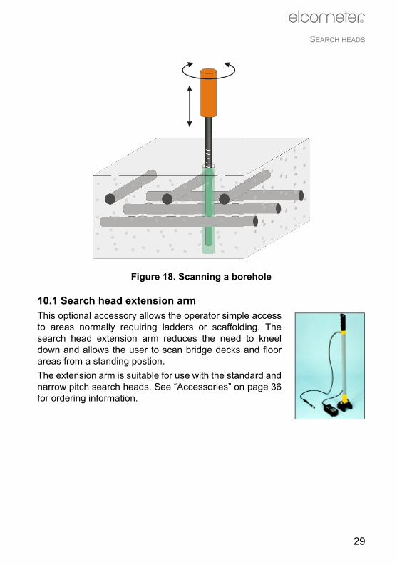
Figure 18. Scanning a borehole
10.1 Search head extension armThis optional accessory allows the operator simple accessto areas normally requiring ladders or scaffolding. Thesearch head extension arm reduces the need to kneeldown and allows the user to scan bridge decks and floorareas from a standing postion.The extension arm is suitable for use with the standard andnarrow pitch search heads. See “Accessories” on page 36for ordering information.
29

ERROR MESSAGES
R
11 ERROR MESSAGES
Under certain conditions the Covermeter will display error messages (Figure19). These messages are normally cleared by pressing any one of the softkeys.The cause of the error will be indicated by the message and should be correctedbefore proceeding.
* Contact Elcometer or your Elcometer Supplier to arrange return.
Figure 19. Example error message - search head not connected
Table 1: Error messages
Error message Causes Action to take
#1 - PROBE Search head-to-gauge communication failure.
Remove search head and refit.If error persists, return to Elcometer*.
#2 - PROBE Corrupt data output from probe.
Try new search head.If error persists, return to Elcometer*.
#3 - PROBE Internal error. Return to Elcometer*.#4 - PROBE Search head power supply
fault.Remove probe. If error persists, the Covermeter is faulty. If error clears, the probe is faulty.Return faulty part to Elcometer*.
#5 - PROBE Internal error. Remove search head and refit.If error persists, return to Elcometer*.
PROBE UNSUPPORTED
Old Covermeter software does not support new search head.
Return to Elcometer* for software upgrade.
PROBE CHANGED
Probe has been changed and is not compatible with current batch.
Change to probe used when batch was created.
VALUE TOO LARGE
Numerical error. Switch Covermeter off then on again.If error persists contact Elcometer.
CLOCK Internal error. Return to Elcometer*.LANGUAGE MEMORY
Software error. Return to Elcometer*.
30

PERSONALISED WELCOME SCREEN
R
12 PERSONALISED WELCOME SCREEN
A personalised welcome screen can be designed on a computer and thendownloaded into the Covermeter.Screen dimensions are 128 pixels x 64 pixels. The welcome screen is typicallyused to personalise the Covermeter with a logo, serial number, user name, etc.This is the first screen displayed when the Covermeter is switched on.
12.1 Creating the screen1. Download Elcometer ‘Welcome Screen Wizard’ software. This software is
available free of charge from the downloads section of the Elcometer website, www.elcometer.com
2. Connect Covermeter to PC using optional Data Transfer Cable - see“Accessories” on page 36.
3. Switch on the Covermeter.4. Ensure that the reading screen is displayed.5. Run ‘Welcome Screen Wizard’ software and follow the on-screen
instructions.
12.2 Deleting the screen1. Run the ‘Welcome Screen Wizard’ software.2. Click ‘Next’.3. Select ‘Create a new screen setup’.4. Click ‘Next’.5. Select ‘Disabled’.6. Click ‘Next’.Follow the remaining on-screen instructions to delete the welcome screen.
31

STORAGE
R
13 STORAGE
This Covermeter incorporates a Liquid Crystal Display (LCD). If thedisplay is heated above 50°C (120°F) it may be damaged. This canhappen if the Covermeter is left in a car parked in strong sunlight.Always store the Covermeter in its case when it is not being used.
14 MAINTENANCE
You own one of the finest covermeters in the world. If looked after, it will last alifetime.Regular calibration checks over the life of the Covermeter are a requirement ofquality management procedures, e.g. ISO 9000, and other similar standards.For checks and certification contact Elcometer or your Elcometer supplier.The Covermeter does not contain any user-serviceable components. In theunlikely event of a fault, the Covermeter should be returned to your Elcometersupplier or directly to Elcometer.Contact details can be found:• Stored in the Covermeter ( MENU / ABOUT / CONTACT).• On the outside cover of these operating instructions.• At www.elcometer.com
15 UPGRADING YOUR COVERMETER
Gain extra functionality from your Covermeter by upgrading your ElcometerProtovale 331 model ‘B’ to a model with higher specification.Upgrading your Covermeter to a model ‘S’ will provide you with the followingadditional features:• Automatic bar sizing• Orthogonal bar sizing• Minimum / maximum cover limits• Maximum PIP mode• Memory of up to 1000 readings in a single linear batch• Statistics• Data transfer cable
32

RELATED EQUIPMENT
R
• EDTS+ data transfer software• CoverMaster® SoftwareUpgrading your Covermeter to a model ‘T’ will provide all the features of amodel ‘S’ plus:• Memory of over 65 000 readings in multiple linear and grid batches• Batch header fields for text, notes, etc.• Date and time stamping of measurementsUpgrading of your Covermeter must be carried out by Elcometer or your localElcometer supplier.Your upgraded Covermeter will be returned to you with:• A CD ROM containing EDTS+ data transfer software and CoverMaster
software.• A data transfer cable.• Operating instructions for a model ‘S’ or model ‘T’ Covermeter.For more information, or to arrange to have your Covermeter upgraded, contactElcometer, your Elcometer supplier or visit www.elcometer.com
16 RELATED EQUIPMENT
Elcometer produces a wide range of concrete and coatings inspectionequipment. Users of the Elcometer Protovale 331 Concrete Covermeter mayalso benefit from the following Elcometer products:• Elcometer Adhesion and Bond Strength Testers• Elcometer Concrete Crack Microscopes• Elcometer Concrete Moisture Meters• Elcometer Concrete Test HammersFor further information contact Elcometer, your Elcometer supplier or visitwww.elcometer.com
33
TECHNICAL DATA
R
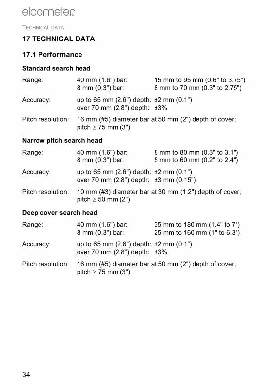
17 TECHNICAL DATA
17.1 Performance
Standard search head
Range: 40 mm (1.6") bar: 15 mm to 95 mm (0.6" to 3.75")8 mm (0.3") bar: 8 mm to 70 mm (0.3" to 2.75")
Accuracy: up to 65 mm (2.6") depth: ±2 mm (0.1")over 70 mm (2.8") depth: ±3%
Pitch resolution: 16 mm (#5) diameter bar at 50 mm (2") depth of cover;pitch ≥ 75 mm (3")
Narrow pitch search head
Range: 40 mm (1.6") bar: 8 mm to 80 mm (0.3" to 3.1")8 mm (0.3") bar: 5 mm to 60 mm (0.2" to 2.4")
Accuracy: up to 65 mm (2.6") depth: ±2 mm (0.1")over 70 mm (2.8") depth: ±3 mm (0.15")
Pitch resolution: 10 mm (#3) diameter bar at 30 mm (1.2") depth of cover;pitch ≥ 50 mm (2")
Deep cover search head
Range: 40 mm (1.6") bar: 35 mm to 180 mm (1.4" to 7")8 mm (0.3") bar: 25 mm to 160 mm (1" to 6.3")
Accuracy: up to 65 mm (2.6") depth: ±2 mm (0.1")over 70 mm (2.8") depth: ±3%
Pitch resolution: 16 mm (#5) diameter bar at 50 mm (2") depth of cover;pitch ≥ 75 mm (3")
34
TECHNICAL DATA
R
17.2 PhysicalWeight: 1.54 kg (3.4 lb)(including Standard search head)
Dimensions: 230 mm x 130 mm x 125 mm(including search head and lead) (9" x 5.1" x 4.9")
Operating temperatureh: 0°C to 50°C(32°F to 120°F)
Case: High impact ABS
17.3 Power supplyInternal rechargeable Lithium Ion batteryi.Fuse rating of charger: 3 ABattery life. Up to 32 hours continuous use without backlight. Up to 20 hourswith backlight.
17.4 CertificationA calibration certificate is supplied as standard with the Covermeter.
17.5 PackagingThe Covermeter is packed in cardboard and plastic packaging. Please ensurethat this packaging is disposed of in an environmentally sensitive manner.Consult your Local Environmental Authority for further guidance.
h. Operation outside these limits depends upon climatic conditions.i. Battery packs must be disposed of carefully to avoid environmental contamination.
Please consult your local environmental authority for information on disposal in yourregion. Do not dispose of the battery pack in a fire.
35
ACCESSORIES
R
18 ACCESSORIES
Your Covermeter is complete with all the items required to get started.The following optional accessories are available from Elcometer, or yourElcometer supplier. To place an order please quote the sales part numberwhich follows the description of each accessory.
Rechargeable battery pack: TW33119038
Search head - standard: TW33119124-1
Search head - narrow pitch: TW33119124-2
Search head - deep cover: TW33119171
Search head - borehole probe, 400 mm (metric): TW33119223-1
Search head - borehole probe, 1000 mm (metric): TW33119223-2
Search head - borehole probe, 16" (imperial): TW33119223-3
Search head - borehole probe, 40" (imperial): TW33119223-4
Search head extension arm: TW33119222
Search head connecting cable: TW33119201
Earphone: TW99912220
Calibration check block: TW33119218
Data transfer cablej (Covermeter to PC): T99916217
RS232 to USB transfer cable: T99916716
Elcometer Protovale 331 Model B to S upgrade TWUPGRADE0-A +TWUPGRADE0-B
Elcometer Protovale 331 Model B to T upgrade TWUPGRADE1-A +TWUPGRADE1-B
Calibration certificateCertificates traceable to National Standards including UKAS and NIST areavailable on request.
j. A 9-pin to 25-pin adapter may be required for certain PC RS232 ports.
36

INDEX
R
19 INDEX
AAccessories 36Accuracy
Depth of cover 22ASTM/Canadian bar size 23
BBacklight 12Bar size
Manual selection of 23Batteries
Charging 4Life of 35
Battery condition indicator 6Battery pack 4Borehole Probe 27
CCalibration 32Calibration certificates 36Certification 35Charger 4Charging the batteries 4Computer
Connection cable 36Cover 21
DData transfer cable 36Deep Cover search head 27Depth of cover 21Dimensions 35
EEarphones 13Elcometer Protovale 331
Features 2Overview 1
Error messages 30
FFeatures 2Fitting a search head 6
HHeadphones 13
IImperial bar size 23Interface 12
Access cover 5RS232 12
JJapanese bar size 23Joined bars 25
KKeypad
Function 8Main unit 7Search head 9
LLanguage, selecting 12LCD contrast 11LED
Illuminated 17Liquid Crystal Display 32Locating 16
Single layer of bars 16Two layers of bars 17
37

INDEX
R
MMaintenance 32Mapping 20Menu items
ABOUT 15AUTO SWITCH OFF 10BACKLIGHT 12BAR 23CONTACT 32HELP 11LCD CONTRAST 11MENU 14RESET 15SERIES 23SETUP 15ZERO 13
Menus 14Metric bar size 23Muting the sound 24
NNarrow Pitch search head 27
OOn/off 10Opening screen
Creating 31Orientation 19Over-range 22
PPackaging 35PC
Data transfer cable 36
Power on/off 10Power supply 4, 35
QQuick-start 4
SScreen
Welcome information 10Screen symbols 11
Battery condition 6Search head
Borehole Probe 27Deep Cover 27
Specifications 34Extension arm 29Fitting 6Narrow Pitch 27
Specifications 34Overview 27Standard 27
Specifications 34Storage clip 7
Sensitivity 24Sound
Muting 24Standard search head 27Standards 3Storage 32Surface mapping 20Switching on/off 10
UUpgrading 32
WWeight 35Welcome screen
Creating 31
38

INDEX
R
Welded mesh 25
ZZeroing the Covermeter 13
39

INDEX
R
40