Embed Size (px)
DESCRIPTION
ELCO, Wellhead Running Procedures
Citation preview

1
FIELD INSTALLATION PROCEDURES
13‐5/8” API 5M x 13‐3/8” SOW CASING HEAD, 13‐5/8” API 5M x 11” API 10M CASING SPOOL,
11” API 10M x 11” 10M TUBING SPOOL, 11” API 10M x 3‐1/16” 10M DOUBLE MASTER TREE,
AND
RELATED RUNNING EQUIPMENT
13-3/8” x 9-5/8” x 7” Casing Program
3-1/2” 7.7# JFE BEAR Tubing Program
Copy
Prepared for: Harvest
Well #’s:
The information contained in this procedure is subject to change without notice.
© 2011 ELCO All rights reserved. Printed in the USA
First Edition (September 2011)
2
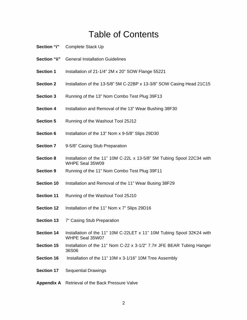
Table of Contents Section “i” Complete Stack Up
Section “ii” General Installation Guidelines
Section 1 Installation of 21-1/4” 2M x 20” SOW Flange 55221
Section 2 Installation of the 13-5/8” 5M C-22BP x 13-3/8” SOW Casing Head 21C15
Section 3 Running of the 13” Nom Combo Test Plug 39F13
Section 4 Installation and Removal of the 13” Wear Bushing 38F30
Section 5 Running of the Washout Tool 25J12
Section 6 Installation of the 13” Nom x 9-5/8” Slips 29D30
Section 7 9-5/8” Casing Stub Preparation
Section 8 Installation of the 11” 10M C-22L x 13-5/8” 5M Tubing Spool 22C34 with WHPE Seal 35W09
Section 9 Running of the 11” Nom Combo Test Plug 39F11
Section 10 Installation and Removal of the 11” Wear Busing 38F29
Section 11 Running of the Washout Tool 25J10
Section 12 Installation of the 11” Nom x 7” Slips 29D16
Section 13 7” Casing Stub Preparation
Section 14 Installation of the 11” 10M C-22LET x 11” 10M Tubing Spool 32K24 with WHPE Seal 35W07
Section 15 Installation of the 11” Nom C-22 x 3-1/2” 7.7# JFE BEAR Tubing Hanger 36S06
Section 16 Installation of the 11” 10M x 3-1/16” 10M Tree Assembly
Section 17 Sequential Drawings
Appendix A Retrieval of the Back Pressure Valve
*DIMENSIONS ARE SUBJECT TO CHANGE ACCORDING TO ACTUAL FIELD CONDITIONS
ELCO CONTROL SHEET
NOTICE:
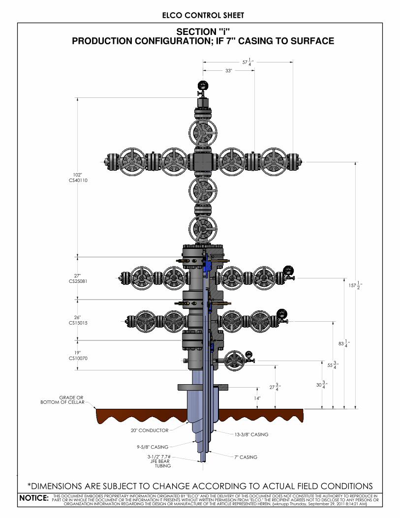
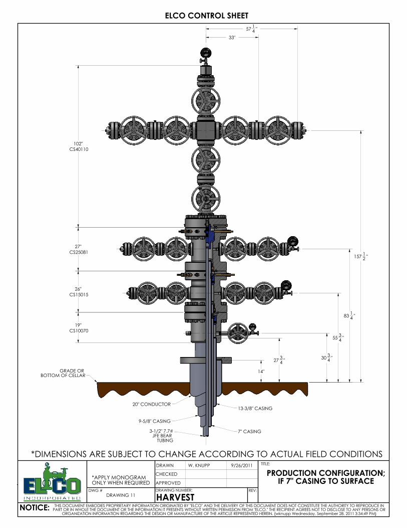
SECTION "i" PRODUCTION CONFIGURATION; IF 7" CASING TO SURFACE
THIS DOCUMENT EMBODIES PROPRIETARY INFORMATION ORIGINATED BY "ELCO" AND THE DELIVERY OF THIS DOCUMENT DOES NOT CONSTITUTE THE AUTHORITY TO REPRODUCE IN PART OR IN WHOLE THE DOCUMENT OR THE INFORMATION IT PRESENTS WITHOUT WRITTEN PERMISSION FROM "ELCO." THE RECIPIENT AGREES NOT TO DISCLOSE TO ANY PERSONS OR
ORGANIZATION INFORMATION REGARDING THE DESIGN OR MANUFACTURE OF THE ARTICLE REPRESENTED HEREIN. {wknupp Thursday, September 29, 2011 8:14:21 AM}
GRADE OR BOTTOM OF CELLAR
20" CONDUCTOR13-3/8" CASING
9-5/8" CASING
7" CASING3-1/2" 7.7#JFE BEAR TUBING
19"
CS10070
26"
CS15015
27"
CS25081
102"
CS40110
3034 "
5534 "
8314 "
15712 "
14"
33"
5714 "
2734 "
ELCO CONTROL SHEET
NOTICE:
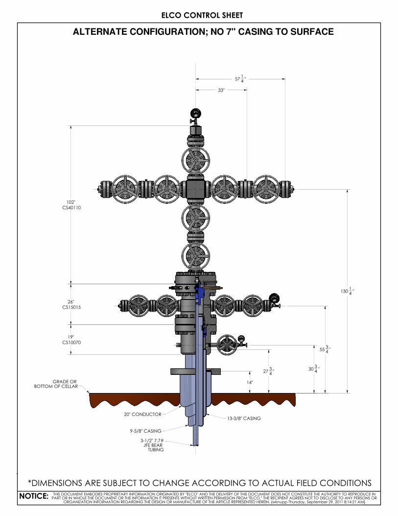
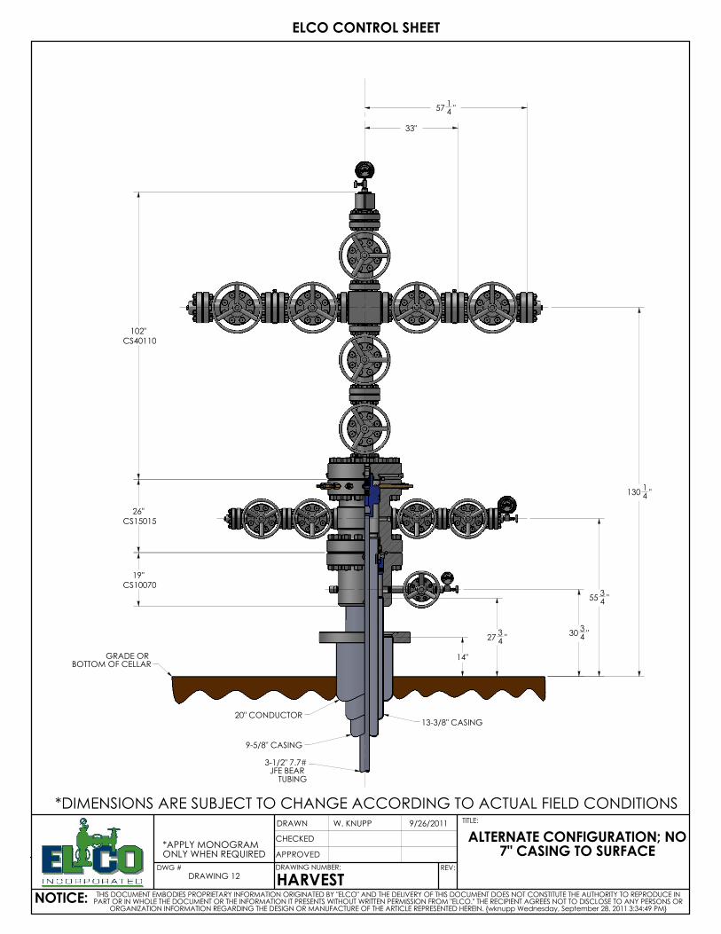
ALTERNATE CONFIGURATION; NO 7" CASING TO SURFACE
THIS DOCUMENT EMBODIES PROPRIETARY INFORMATION ORIGINATED BY "ELCO" AND THE DELIVERY OF THIS DOCUMENT DOES NOT CONSTITUTE THE AUTHORITY TO REPRODUCE IN PART OR IN WHOLE THE DOCUMENT OR THE INFORMATION IT PRESENTS WITHOUT WRITTEN PERMISSION FROM "ELCO." THE RECIPIENT AGREES NOT TO DISCLOSE TO ANY PERSONS OR
ORGANIZATION INFORMATION REGARDING THE DESIGN OR MANUFACTURE OF THE ARTICLE REPRESENTED HEREIN. {wknupp Thursday, September 29, 2011 8:14:21 AM}
*DIMENSIONS ARE SUBJECT TO CHANGE ACCORDING TO ACTUAL FIELD CONDITIONS
GRADE OR BOTTOM OF CELLAR
20" CONDUCTOR13-3/8" CASING
9-5/8" CASING
3-1/2" 7.7#JFE BEAR TUBING
19"CS10070
26"CS15015
102"
CS40110
3034 "
5534 "
13014 "
14"
33"
5714 "
2734 "
UDONLY WHEN REQUIRED*APPLY MONOGRAM
1954.84 LBS
DRAWN
9/12/2011
WEIGHT:
ELCO CONTROL SHEET
9/9/2011
CHECKED
APPROVED
N. DHANENS
CS10070DRAWING NUMBER:
TITLE:
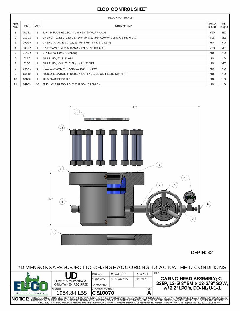
Aw/2 2" LPO's, DD-NL-U-1-1
22BP, 13-5/8" 5M x 13-3/8" SOW,
C. WALKER
NOTICE:
CASING HEAD ASSEMBLY; C-
ORGANIZATION INFORMATION REGARDING THE DESIGN OR MANUFACTURE OF THE ARTICLE REPRESENTED HEREIN. {cwalker Monday, September 12, 2011 12:12:34 PM}
THIS DOCUMENT EMBODIES PROPRIETARY INFORMATION ORIGINATED BY "ELCO" AND THE DELIVERY OF THIS DOCUMENT DOES NOT CONSTITUTE THE AUTHORITY TO REPRODUCE IN PART OR IN WHOLE THE DOCUMENT OR THE INFORMATION IT PRESENTS WITHOUT WRITTEN PERMISSION FROM "ELCO." THE RECIPIENT AGREES NOT TO DISCLOSE TO ANY PERSONS OR
REV:
*DIMENSIONS ARE SUBJECT TO CHANGE ACCORDING TO ACTUAL FIELD CONDITIONS
BILL OF MATERIALS
ITEM NO. INV. QTY. DESCRIPTION MONO
REQ'DS/N
REQ'D
1 55221 1 SLIP ON FLANGE; 21-1/4" 2M x 20" SOW, AA-U-1-1 YES YES
2 21C15 1 CASING HEAD; C-22BP, 13-5/8" 5M x 13-3/8" SOW w/2 2" LPOs, DD-U-1-1 YES YES
3 29D30 1 CASING HANGER; C-22, 13-5/8" Nom x 9-5/8" Casing NO NO
4 63D22 1 GATE VAVLE; M, 2-1/16" 5M x 2" LP, S/E, DD-U-1-1 YES YES
5 61A32 1 NIPPLE; XXH, 2" LP x 8" Long NO NO
6 61I28 1 BULL PLUG; 2" LP, PLAIN NO NO
7 61I30 1 BULL PLUG; XXH, 2" LP, Tapped 1/2" NPT NO YES
8 63A46 1 NEEDLE VALVE; M/F ANGLE, 1/2" NPT, 10M NO NO
9 69112 1 PRESSURE GAUGE; 0-10000, 4-1/2" FACE, LIQUID FILLED, 1/2" NPT NO NO
10 68B60 1 RING GASKET; BX-160 NO NO
11 64B09 16 STUD; W/2 NUTS X 1 5/8'' X 12 3/4'' 2H BLACK NO NO
8
7
10
11
2
6
1
5 4
9
3
DEPTH: 32"
19"
47"
14
2
12
7
6
4 5 35
36
5
5
3 5 6 3
65
4
8
91
10
11
26"
115"
*DIMENSIONS ARE SUBJECT TO CHANGE ACCORDING TO ACTUAL FIELD CONDITIONS
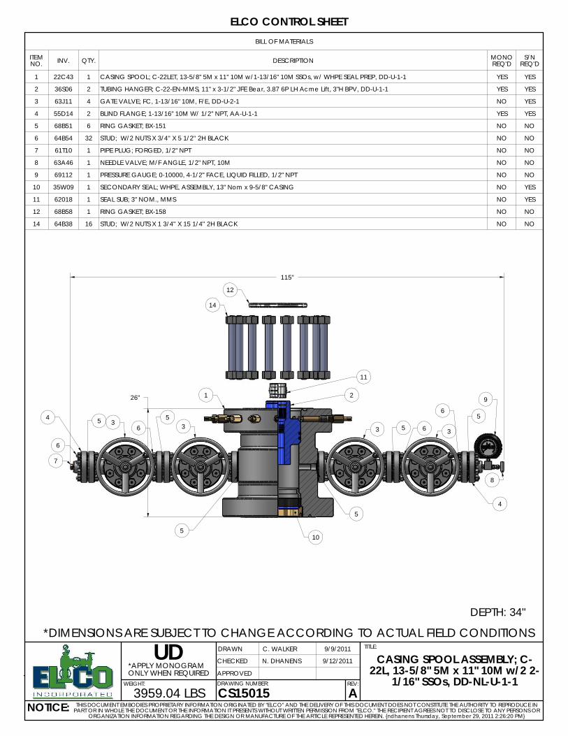
DEPTH: 34"
BILL OF MATERIALS
ITEM NO. INV. QTY. DESCRIPTION MONO
REQ'DS/N
REQ'D
1 22C43 1 CASING SPOOL; C-22LET, 13-5/8" 5M x 11" 10M w/1-13/16" 10M SSOs, w/ WHPE SEAL PREP, DD-U-1-1 YES YES
2 36S06 2 TUBING HANGER; C-22-EN-MMS, 11" x 3-1/2" JFE Bear, 3.87 6P LH Acme Lift, 3"H BPV, DD-U-1-1 YES YES
3 63J11 4 GATE VALVE; FC, 1-13/16" 10M, F/E, DD-U-2-1 NO YES
4 55D14 2 BLIND FLANGE; 1-13/16" 10M W/ 1/2" NPT, AA-U-1-1 YES YES
5 68B51 6 RING GASKET; BX-151 NO NO
6 64B54 32 STUD; W/2 NUTS X 3/4'' X 5 1/2'' 2H BLACK NO NO
7 61T10 1 PIPE PLUG; FORGED, 1/2" NPT NO NO
8 63A46 1 NEEDLE VALVE; M/F ANGLE, 1/2" NPT, 10M NO NO
9 69112 1 PRESSURE GAUGE; 0-10000, 4-1/2" FACE, LIQUID FILLED, 1/2" NPT NO NO
10 35W09 1 SECONDARY SEAL; WHPE, ASSEMBLY, 13" Nom x 9-5/8" CASING NO YES
11 62018 1 SEAL SUB; 3" NOM., MMS NO YES
12 68B58 1 RING GASKET; BX-158 NO NO
14 64B38 16 STUD; W/2 NUTS X 1 3/4'' X 15 1/4'' 2H BLACK NO NO
UDONLY WHEN REQUIRED*APPLY MONOGRAM
3959.04 LBSWEIGHT:
ELCO CONTROL SHEET
9/9/2011
CHECKED
APPROVED
N. DHANENS
C. WALKER
NOTICE:
9/12/2011
DRAWN
1/16" SSOs, DD-NL-U-1-1
TITLE:
A
22L, 13-5/8" 5M x 11" 10M w/2 2-CASING SPOOL ASSEMBLY; C-
ORGANIZATION INFORMATION REGARDING THE DESIGN OR MANUFACTURE OF THE ARTICLE REPRESENTED HEREIN. {ndhanens Thursday, September 29, 2011 2:26:20 PM}
DRAWING NUMBER:
CS15015THIS DOCUMENT EMBODIES PROPRIETARY INFORMATION ORIGINATED BY "ELCO" AND THE DELIVERY OF THIS DOCUMENT DOES NOT CONSTITUTE THE AUTHORITY TO REPRODUCE IN
PART OR IN WHOLE THE DOCUMENT OR THE INFORMATION IT PRESENTS WITHOUT WRITTEN PERMISSION FROM "ELCO." THE RECIPIENT AGREES NOT TO DISCLOSE TO ANY PERSONS OR
REV:
*DIMENSIONS ARE SUBJECT TO CHANGE ACCORDING TO ACTUAL FIELD CONDITIONS
BILL OF MATERIALS
ITEM NO. INV. QTY. DESCRIPTION MONO
REQ'DS/N
REQ'D
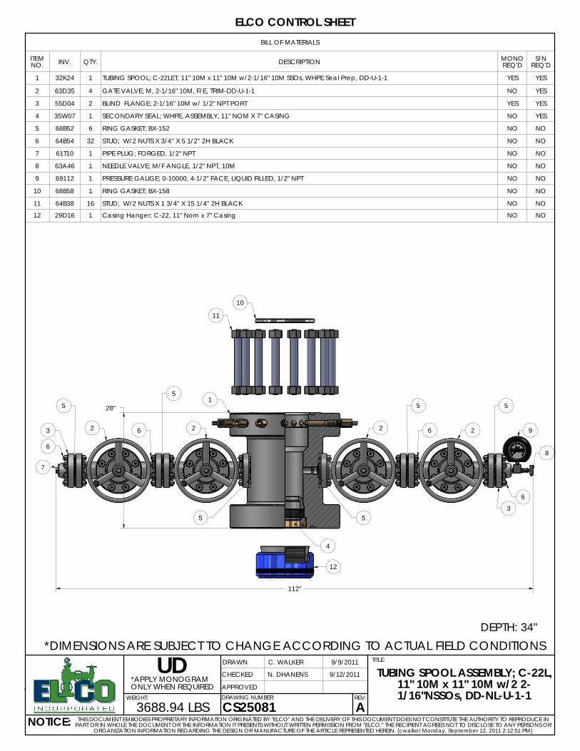
1 32K24 1 TUBING SPOOL; C-22LET, 11" 10M x 11" 10M w/2-1/16" 10M SSOs, WHPE Seal Prep, DD-U-1-1 YES YES
2 63D35 4 GATE VALVE; M, 2-1/16" 10M, F/E, TRIM-DD-U-1-1 NO YES
3 55D04 2 BLIND FLANGE; 2-1/16" 10M w/ 1/2" NPT PORT YES YES
4 35W07 1 SECONDARY SEAL; WHPE, ASSEMBLY, 11" NOM X 7" CASING NO YES
5 68B52 6 RING GASKET; BX-152 NO NO
6 64B54 32 STUD; W/2 NUTS X 3/4'' X 5 1/2'' 2H BLACK NO NO
7 61T10 1 PIPE PLUG; FORGED, 1/2" NPT NO NO
8 63A46 1 NEEDLE VALVE; M/F ANGLE, 1/2" NPT, 10M NO NO
9 69112 1 PRESSURE GAUGE; 0-10000, 4-1/2" FACE, LIQUID FILLED, 1/2" NPT NO NO
10 68B58 1 RING GASKET; BX-158 NO NO
11 64B38 16 STUD; W/2 NUTS X 1 3/4'' X 15 1/4'' 2H BLACK NO NO
12 29D16 1 Casing Hanger; C-22, 11" Nom x 7" Casing NO NO
ONLY WHEN REQUIRED
UD*APPLY MONOGRAM
3688.94 LBS
9/12/2011
WEIGHT:
ELCO CONTROL SHEET
9/9/2011
CHECKED
APPROVED
N. DHANENS
C. WALKERDRAWN
CS25081 A1/16"NSSOs, DD-NL-U-1-1
TITLE:
11" 10M x 11" 10M w/2 2-
NOTICE:
TUBING SPOOL ASSEMBLY; C-22L,
ORGANIZATION INFORMATION REGARDING THE DESIGN OR MANUFACTURE OF THE ARTICLE REPRESENTED HEREIN. {cwalker Monday, September 12, 2011 2:12:51 PM}
DRAWING NUMBER:
THIS DOCUMENT EMBODIES PROPRIETARY INFORMATION ORIGINATED BY "ELCO" AND THE DELIVERY OF THIS DOCUMENT DOES NOT CONSTITUTE THE AUTHORITY TO REPRODUCE IN PART OR IN WHOLE THE DOCUMENT OR THE INFORMATION IT PRESENTS WITHOUT WRITTEN PERMISSION FROM "ELCO." THE RECIPIENT AGREES NOT TO DISCLOSE TO ANY PERSONS OR
REV:
6
7
6
3 2
5
5
6 2
5
1
11
10
2 6 2
5
35
8
9
5
4
12
DEPTH: 34"
28"
112"
8
12
1
9
3
17
9
3
33333
10
4
9
9 9
99
99
9
13
7
6
5
9 9 4
9
10
11
5
11
10
10
2
13
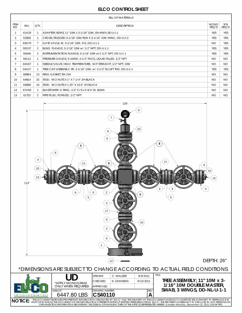
DEPTH: 26"
113"
126"
*DIMENSIONS ARE SUBJECT TO CHANGE ACCORDING TO ACTUAL FIELD CONDITIONS
BILL OF MATERIALS
ITEM NO. INV. QTY. DESCRIPTION MONO
REQ'DS/N
REQ'D
1 41A33 1 ADAPTER; B2MS; 11" 10M x 3-1/16" 10M, EN-MMS, EE-U-1-1 YES YES
2 52B35 1 CROSS; STUDDED 3-1/16" 10M RUN X 3-1/16" 10M WING, DD-U-2-2 YES YES
3 63D79 7 GATE VAVLE; M, 3-1/16" 10M, F/E, DD-U-1-1 NO YES
4 55D37 2 BLIND FLANGE; 3-1/16" 10M w/ 1/2" NPT, DD-U-1-1 YES YES
5 55646 2 INSTRUMENTATION FLANGE; 3-1/16" 10M w/2 1/2" NPT, DD-U-1-1 YES YES
6 69112 1 PRESSURE GAUGE; 0-10000, 4-1/2" FACE, LIQUID FILLED, 1/2" NPT NO NO
7 63A67 1 NEEDLE VALVE; HIGH TEMPERATURE, M/F STRAIGHT, 1/2" NPT, 10M NO NO
8 54A27 1 TREE CAP ASSEMBLY; RF, 3-1/16" 10M, w/ 3-1/2" EU LIFT THD, DD-U-1-1 YES YES
9 68B54 13 RING GASKET; BX-154 NO NO
10 64B14 32 STUD; W/2 NUTS X 1'' X 7 1/4'' 2H BLACK NO NO
11 64B08 16 STUD; W/2 NUTS X 1.25'' X 10.5'' 2H BLACK NO NO
12 67A59 1 ELASTOMER; O RING, 1/2" C/S x 5-3/4" ID, BUNA NO NO
13 61T10 2 PIPE PLUG; FORGED, 1/2" NPT NO NO
ONLY WHEN REQUIRED
UD*APPLY MONOGRAM
6447.80 LBS
9/12/2011
WEIGHT:
ELCO CONTROL SHEET
9/9/2011
CHECKED
APPROVED
N. DHANENS
C. WALKERDRAWN
CS40110 ASWAB, 3 WINGS, DD-NL-U-1-1
TITLE:
1/16" 10M DOUBLE MASTER,
NOTICE:
TREE ASSEMBLY; 11" 10M x 3-
ORGANIZATION INFORMATION REGARDING THE DESIGN OR MANUFACTURE OF THE ARTICLE REPRESENTED HEREIN. {cwalker Monday, September 12, 2011 2:05:08 PM}
DRAWING NUMBER:
THIS DOCUMENT EMBODIES PROPRIETARY INFORMATION ORIGINATED BY "ELCO" AND THE DELIVERY OF THIS DOCUMENT DOES NOT CONSTITUTE THE AUTHORITY TO REPRODUCE IN PART OR IN WHOLE THE DOCUMENT OR THE INFORMATION IT PRESENTS WITHOUT WRITTEN PERMISSION FROM "ELCO." THE RECIPIENT AGREES NOT TO DISCLOSE TO ANY PERSONS OR
REV:
9
SECTION “ii”: GENERAL INSTALLATION GUIDELINES
NOTE: Make sure you obtain and use all required personal protective equipment prior to beginning any of the procedures that follow. The following information is meant to be a generic installation guide. The casing program is the same as described on the front page. Most wellhead systems are manufactured to specific customer requirements. Hence, the procedures that are detailed in this section should be considered as general and specific only to this
particular system. ELCO recommends that running procedures always be followed for the specific system that is being run. Furthermore, ELCO
recommends that a qualified ELCO service representative always be called for any job pertaining to ELCO equipment.
Before Installation:
1. Verify all equipment used in conjunction with ELCO’s is compatible. This includes
but is not limited to the BOP stack, casing hangers, packoffs, BOP test plugs, bowl protectors, and running tools.
2. Verify the proper emergency equipment is in place and ready for installation.
3. Verify spare parts are available. Examples include elastomer seals, ring gaskets,
and metal-to-metal seals. 4. Check all attached gate valves for proper operation. 5. Verify the proper number and type of ring gaskets, studs, and nuts are available
for the job. 6. When possible, stack up the wellhead system in the shop prior to installation.
7. Make sure you have specific running procedures for the system to be installed. 8. Make sure you always measure from the rig floor (KB) to the point you will be
landing any particular item. This should be done well in advance of the actual job and recorded in your tally book.
10
SECTION 1: INSTALLATION OF THE 21-1/4” 2M x 20” SOW FLANGE 55221
Leveling The flange must be installed so that the top is level, except in cases where the surface casing is not exactly vertical. In this case, the top flange face must be perpendicular to the casing string. Otherwise there will be problems landing subsequent casing strings.
Before Installation
NOTE: Make sure all required personal protective equipment is obtained and used during this operation.
1. Check and record the inventory code of the flange to ensure the proper
equipment is on location. This code should be considered critical. The inventory code of the flange should be 55221. This code is located on the first line of the stamp mark on the flange OD after the name ELCO. Ex.: ELCO 55221.
2. Check the ring gasket grooves and mating surfaces for foreign material, burrs, or
other damage. Dress with emery cloth to restore smoothness.
3. Check compatibility with all associated equipment on location (ie. Diverters, etc.)
Preparation
1. Make rough and final cuts on the 13-3/8” casing See Sequential Drawing 1.
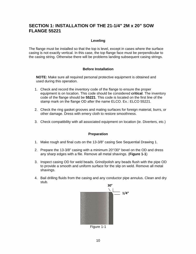
2. Prepare the 13-3/8” casing with a minimum 20°/30° bevel on the OD and dress any sharp edges with a file. Remove all metal shavings. (Figure 1-1)
3. Inspect casing OD for weld beads. Grind/polish any beads flush with the pipe OD to provide a smooth and uniform surface for the slip on weld. Remove all metal shavings.
4. Bail drilling fluids from the casing and any conductor pipe annulus. Clean and dry stub.
Figure 1-1
30°
1/4”
11
Installation Welding Welding should only be performed by a qualified welder hired by the customer. Make sure the weld area is thoroughly cleaned before welding. NOTE: Due to the variety of materials requested for use worldwide, exact weld procedures will not be supplied in this manual. A qualified welder of the customer’s choice should be utilized to weld on casing heads. The ELCO engineering department may be consulted for guidelines. Final procedures and responsibility for the weld rest with the customer’s welder. NOTE: Make sure all required personal protective equipment is obtained and used during this operation.
1. Rig the SOW Flange with wire rope harness and clamp.
WARNING: Never use hemp or nylon rope or chains to suspend or move heavy equipment. Failure to use wire rope could result in dropping the flange and causing severe injury to personnel.
2. Pick up the flange and position over the prepared stub.
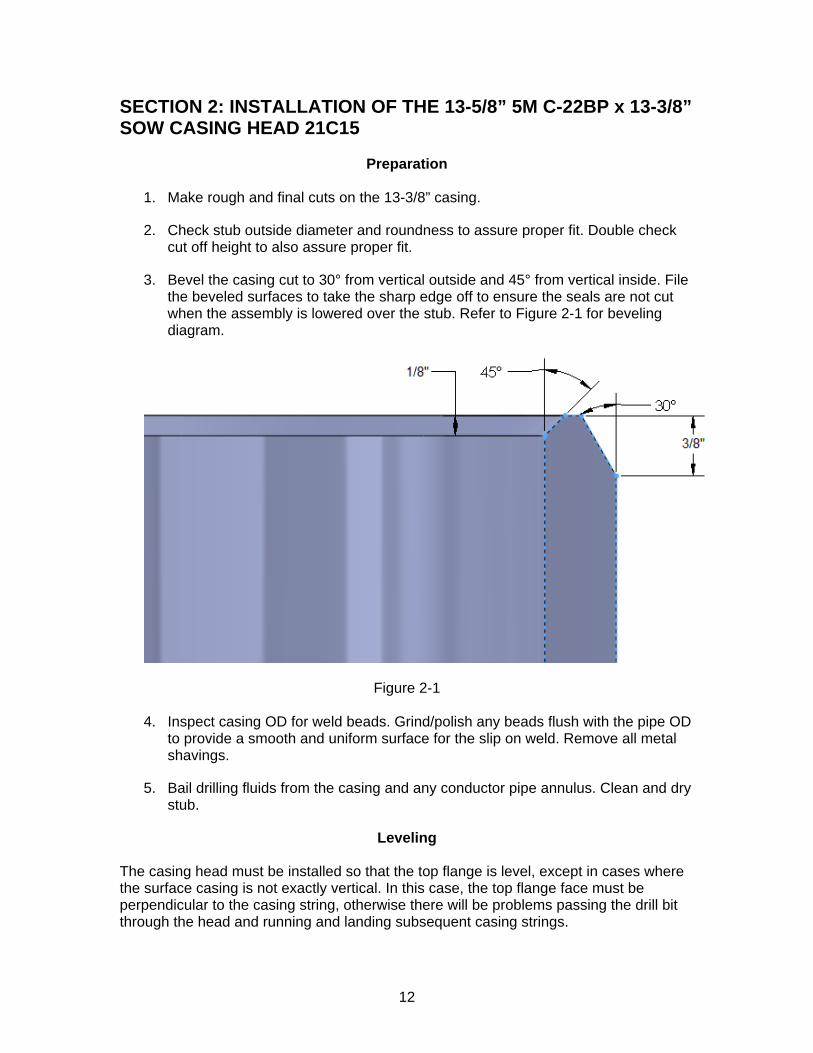
3. Slowly lower the flange onto casing stub. The flange is fully landed when the casing stub bottoms against the lead shoulder at the top of the SOW pocket. Refer to Figure 1-2.
WARNING: Do not put your hands on the casing while the flange is being landed. Failure to keep hands clear could result in crushing or cutting of fingers and hands.
Figure 1-2
4. Level the flange using a sledge hammer and body weight on the chain hoist. Hit
only the bottom of the flange. If casing is not vertical, the casing head may have to be aligned with the casing to avoid drilling or installation problems later on. If casing is off vertical, consult the service manager at ELCO Incorporated for clearance before proceeding.
5. An over-pull test is recommended, and should be done at this time. Limit any over-pull to 2,000 lbs maximum.
6. Obtain and record elevation from top of casing head to rig floor.
12
SECTION 2: INSTALLATION OF THE 13-5/8” 5M C-22BP x 13-3/8” SOW CASING HEAD 21C15
Preparation
1. Make rough and final cuts on the 13-3/8” casing.
2. Check stub outside diameter and roundness to assure proper fit. Double check cut off height to also assure proper fit.
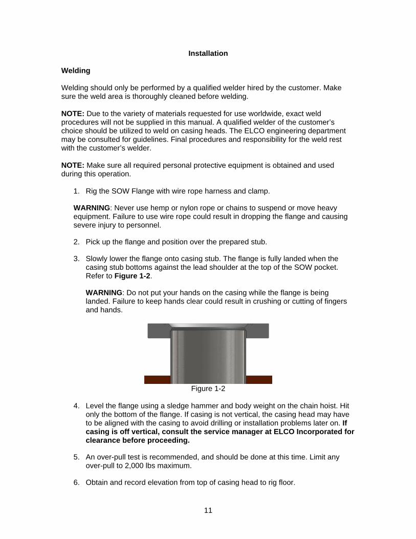
3. Bevel the casing cut to 30° from vertical outside and 45° from vertical inside. File the beveled surfaces to take the sharp edge off to ensure the seals are not cut when the assembly is lowered over the stub. Refer to Figure 2-1 for beveling diagram.
Figure 2-1
4. Inspect casing OD for weld beads. Grind/polish any beads flush with the pipe OD to provide a smooth and uniform surface for the slip on weld. Remove all metal shavings.
5. Bail drilling fluids from the casing and any conductor pipe annulus. Clean and dry stub.
Leveling The casing head must be installed so that the top flange is level, except in cases where the surface casing is not exactly vertical. In this case, the top flange face must be perpendicular to the casing string, otherwise there will be problems passing the drill bit through the head and running and landing subsequent casing strings.
13
Orientation The casing head should establish the proper orientation for the remaining completion equipment. Be sure the side outlets are orientated so that there is ample room to install the valve-removal (VR) lubricator.
Before Installation NOTE: Make sure all required personal protective equipment is obtained and used during this operation.
1. Check the ring gasket grooves and mating surfaces for foreign material, burrs, or other damage. Dress with emery cloth to restore smoothness.
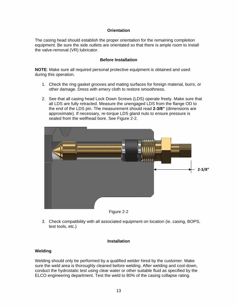
2. See that all casing head Lock Down Screws (LDS) operate freely. Make sure that all LDS are fully retracted. Measure the unengaged LDS from the flange OD to the end of the LDS pin. The measurement should read 2-3/8” (dimensions are approximate). If necessary, re-torque LDS gland nuts to ensure pressure is sealed from the wellhead bore. See Figure 2-2.
Figure 2-2
3. Check compatibility with all associated equipment on location (ie. casing, BOPS,
test tools, etc.)
Installation Welding Welding should only be performed by a qualified welder hired by the customer. Make sure the weld area is thoroughly cleaned before welding. After welding and cool-down, conduct the hydrostatic test using clear water or other suitable fluid as specified by the ELCO engineering department. Test the weld to 80% of the casing collapse rating.
2‐3/8”
14
NOTE: Due to the variety of materials requested for use worldwide, exact weld procedures will not be supplied in this manual. A qualified welder of the customer’s choice should be utilized to weld on casing heads. The ELCO engineering department may be consulted for guidelines. Final procedures and responsibility for the weld rest with the customer’s welder. NOTE: Make sure all required personal protective equipment is obtained and used during this operation.
7. Check orientation of mud valve outlet to see that it will match up to the flowlines.
8. See that there is enough clearance at the site and orientate the head so that the VR lubricator may be attached for valve removal and reinstallation.
9. Remove the 1/2” plug from the casing head test port.
10. Check and record the through bore of the casing head and make sure this dimension is not less that the OD of the casing to which it will be attached.
11. Rig the casing head with wire rope harness and clamp.
WARNING: Never use hemp or nylon rope or chains to suspend or move casing heads. Failure to use wire rope could result in dropping the casing head and causing severe injury to personnel.
12. Pick up casing head and position over the prepared stub. Orientate outlet valves to required direction.
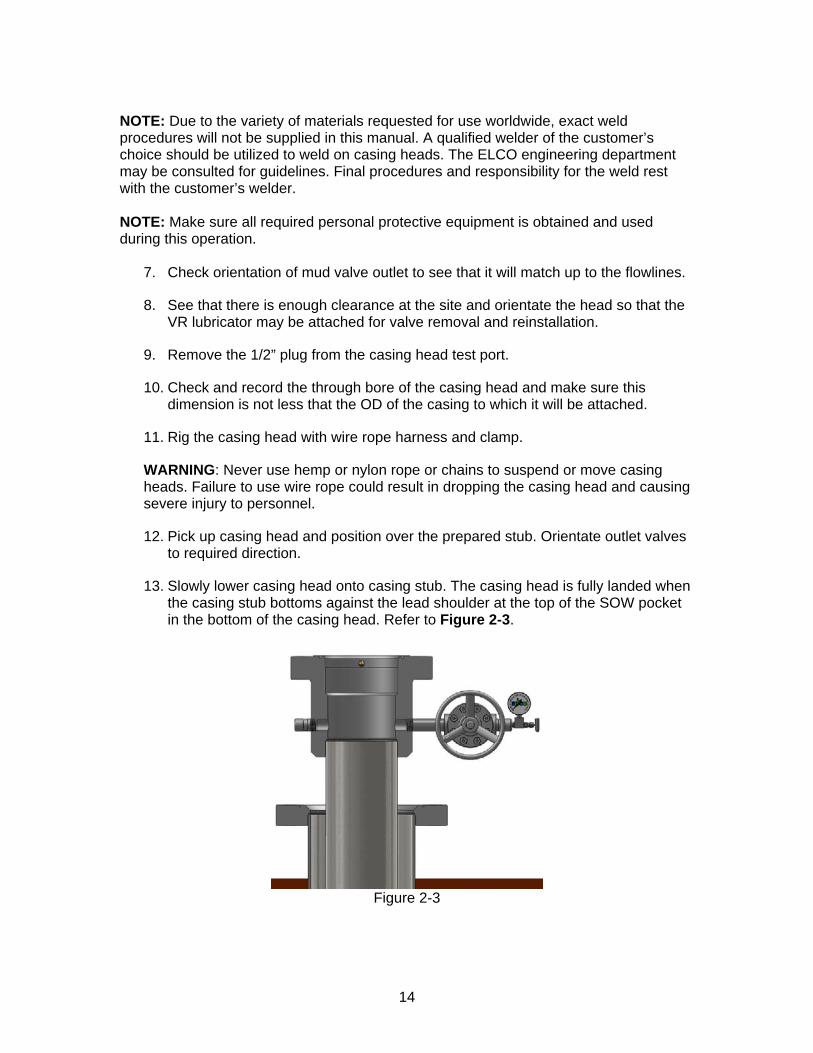
13. Slowly lower casing head onto casing stub. The casing head is fully landed when the casing stub bottoms against the lead shoulder at the top of the SOW pocket in the bottom of the casing head. Refer to Figure 2-3.
Figure 2-3
15
WARNING: Do not put your hands on the casing while the casing head is being landed. Failure to keep hands clear could result in crushing or cutting of fingers and hands.
NOTE: Additional weight may sometimes be required to force the casing head onto the casing due to seal interference and drag.
14. Level the casing head by using a sledge hammer and body weight on the chain hoist. Hit only the bottom of the flange. If casing is not vertical, the casing head may have to be aligned with the casing to avoid drilling or installation problems later on. If casing is off vertical, consult the service manager at ELCO Incorporated for clearance before proceeding.
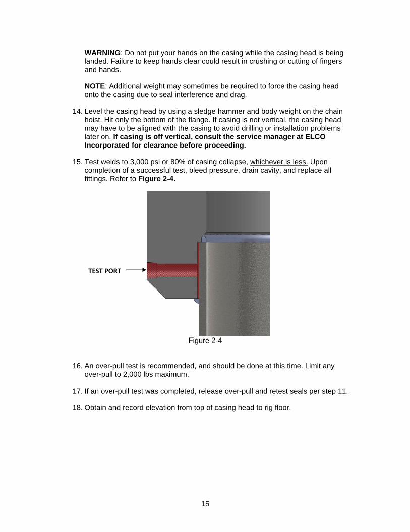
15. Test welds to 3,000 psi or 80% of casing collapse, whichever is less. Upon completion of a successful test, bleed pressure, drain cavity, and replace all fittings. Refer to Figure 2-4.
Figure 2-4
16. An over-pull test is recommended, and should be done at this time. Limit any over-pull to 2,000 lbs maximum.
17. If an over-pull test was completed, release over-pull and retest seals per step 11.
18. Obtain and record elevation from top of casing head to rig floor.
TEST PORT
16
SECTION 3: RUNNING OF THE 13” NOM COMBO TEST PLUG 39F13
Before Installation 1. Make sure the BOP, test plug, and the casing head are compatible. 2. See that all LDS in the casing head operate freely and are fully retracted. See
section 2, step 2 (“Before Installation”) for proper position of retracted LDS. 3. Make sure the blowout preventers are open.
4. Inspect the seals on the test plug for damage and replace if necessary.
5. Make sure weep plugs are in place when testing shear or upper pipe rams.
NOTE: Remove weep plugs when testing the lower most pipe rams as this will allow pressure to escape by the plug in the event of a lower ram leak.
Running Procedure
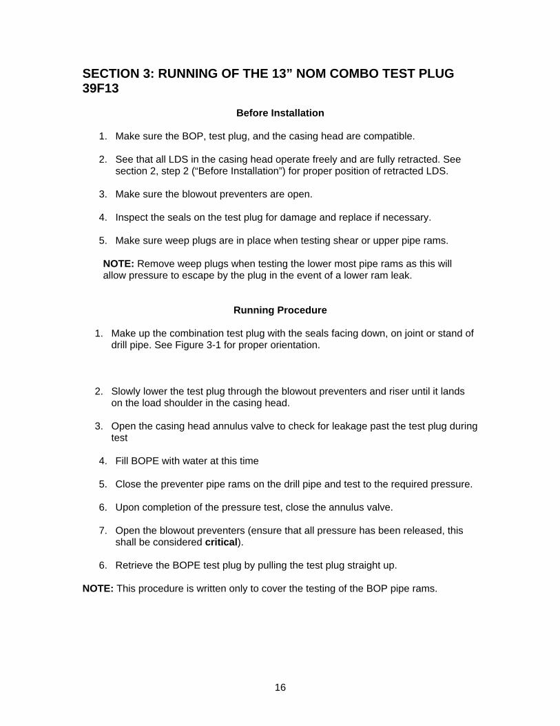
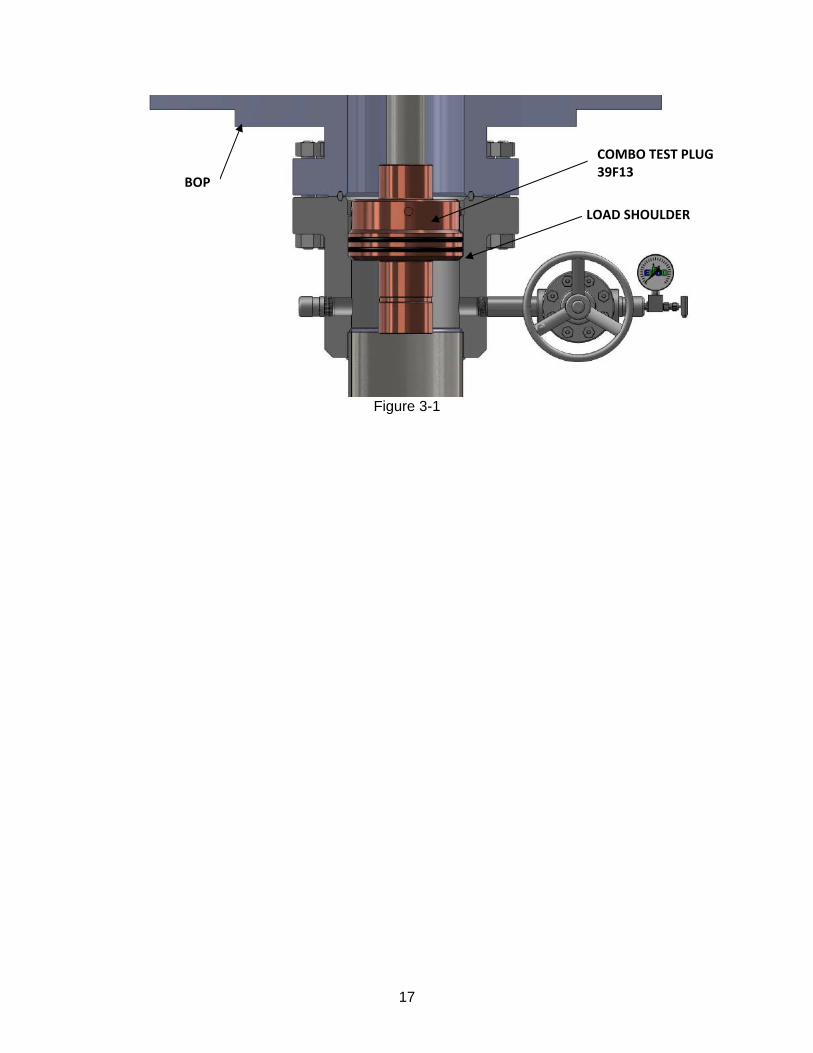
1. Make up the combination test plug with the seals facing down, on joint or stand of drill pipe. See Figure 3-1 for proper orientation.
2. Slowly lower the test plug through the blowout preventers and riser until it lands
on the load shoulder in the casing head.
3. Open the casing head annulus valve to check for leakage past the test plug during test
4. Fill BOPE with water at this time 5. Close the preventer pipe rams on the drill pipe and test to the required pressure. 6. Upon completion of the pressure test, close the annulus valve. 7. Open the blowout preventers (ensure that all pressure has been released, this
shall be considered critical).
6. Retrieve the BOPE test plug by pulling the test plug straight up. NOTE: This procedure is written only to cover the testing of the BOP pipe rams.
17
Figure 3-1
BOP
COMBO TEST PLUG 39F13
LOAD SHOULDER
18
SECTION 4: INSTALLATION AND REMOVAL OF THE 13” WEAR BUSHING 38F30
Before Running 1. Make sure the bowl protector, running tool, and the casing head are compatible. 2. Verify inside diameter of the bowl protector by drifting with the drill bit. The inside
diameter of the bowl protector should be no smaller than 12-5/8” in diameter (dimensions are approximate).
3. See that all LDS in the casing head operate freely and are fully retracted. See
section 2, step 2 (“Before Installation”) for proper position of retracted LDS.
4. Make sure the blowout preventers are open.
5. Make sure running tool is compatible with the drill pipe that will be utilized to run in the wear bushing.
Running Procedure
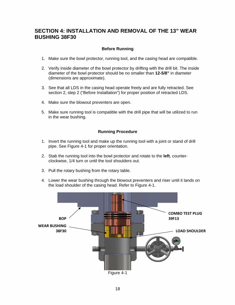
1. Invert the running tool and make up the running tool with a joint or stand of drill pipe. See Figure 4-1 for proper orientation.
2. Stab the running tool into the bowl protector and rotate to the left, counter-
clockwise, 1/4 turn or until the tool shoulders out.
3. Pull the rotary bushing from the rotary table.
4. Lower the wear bushing through the blowout preventers and riser until it lands on the load shoulder of the casing head. Refer to Figure 4-1.
Figure 4-1
BOP
WEAR BUSHING 38F30
COMBO TEST PLUG 39F13
LOAD SHOULDER
19
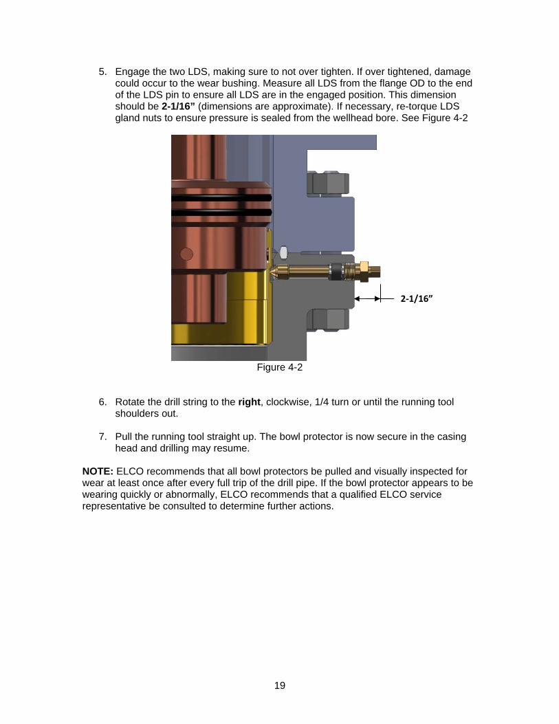
5. Engage the two LDS, making sure to not over tighten. If over tightened, damage could occur to the wear bushing. Measure all LDS from the flange OD to the end of the LDS pin to ensure all LDS are in the engaged position. This dimension should be 2-1/16” (dimensions are approximate). If necessary, re-torque LDS gland nuts to ensure pressure is sealed from the wellhead bore. See Figure 4-2
Figure 4-2
6. Rotate the drill string to the right, clockwise, 1/4 turn or until the running tool shoulders out.
7. Pull the running tool straight up. The bowl protector is now secure in the casing
head and drilling may resume. NOTE: ELCO recommends that all bowl protectors be pulled and visually inspected for wear at least once after every full trip of the drill pipe. If the bowl protector appears to be wearing quickly or abnormally, ELCO recommends that a qualified ELCO service representative be consulted to determine further actions.
2‐1/16”
20
Retrieval Procedures
1. Make up the running tool and a joint or stand of drill pipe. Refer to Figure 4-1 for orientation.
2. Pull the rotary bushing from the rotary table. 3. Slowly lower the running tool through the blowout preventers and riser until it
lands on the wear bushing. 4. Rotate the drill pipe to the left, counter-clockwise, until the string drops. 5. Rotate the drill string to the left 1/4 turn or until the running tool shoulders out. 6. Retract the LDS that were previously engaged. See section 2, step 2 (“Before
Installation”) for proper position of retracted LDS. 7. Pull straight up on the bowl protector and retrieve.
21
SECTION 5: RUNNING OF THE WASHOUT TOOL 25J12
Before Running Tool
1. Verify all required tools and equipment are available, serviceable and ready to run.
Running Procedure
1. Make up a stand of drill pipe with 4 ½” IF (NC50) male threads into the 4 ½” IF
(NC50) female threads on the Washout Tool.
2. Open casing head annular gate valve for drainage.
3. Slowly lower the Washout Tool into the BOPE. Turn the pump on to a flow rate of 3-4 barrels per minute and let it run for a minimum of 15 minutes. As the pump runs, slowly rotate washout tool at a rate of approximately 1-2 RPM.
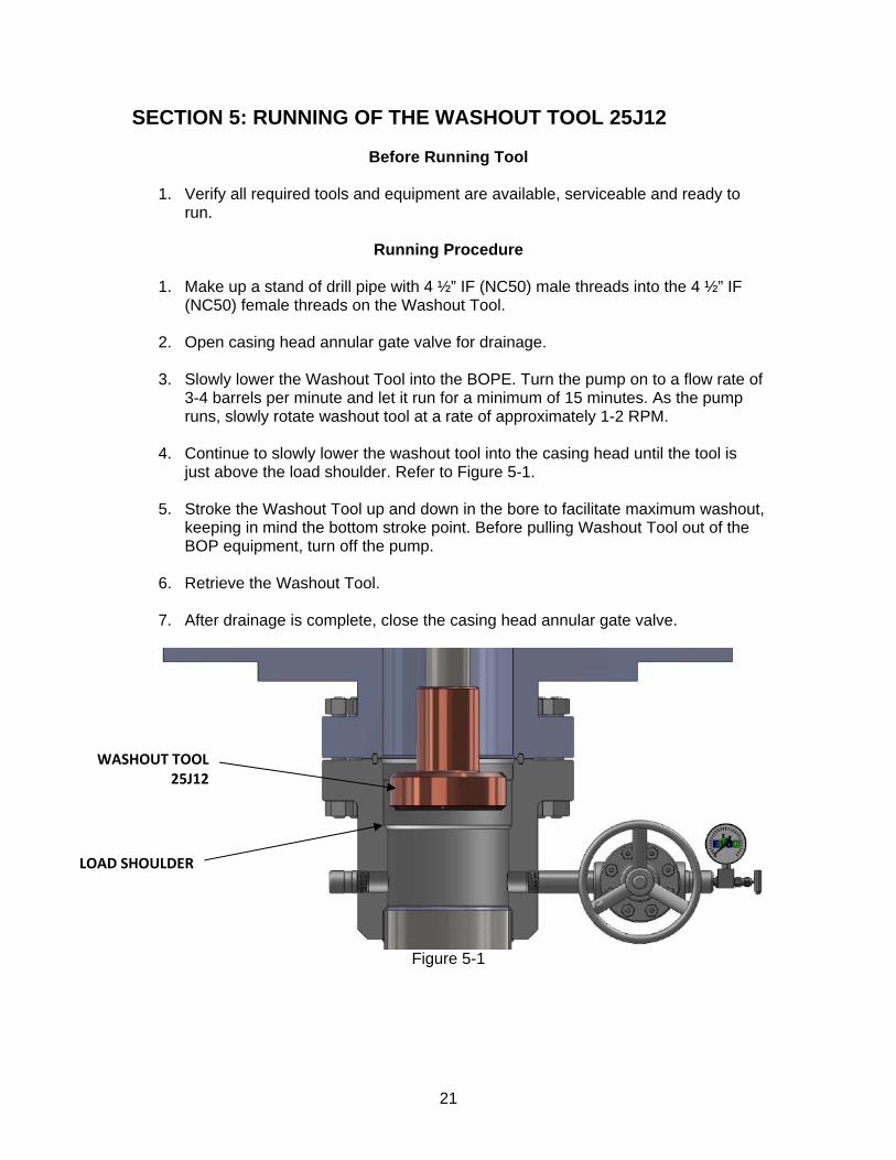
4. Continue to slowly lower the washout tool into the casing head until the tool is just above the load shoulder. Refer to Figure 5-1.
5. Stroke the Washout Tool up and down in the bore to facilitate maximum washout, keeping in mind the bottom stroke point. Before pulling Washout Tool out of the BOP equipment, turn off the pump.
6. Retrieve the Washout Tool.
7. After drainage is complete, close the casing head annular gate valve.
Figure 5-1
WASHOUT TOOL 25J12
LOAD SHOULDER
22
SECTION 6: INSTALLATION OF THE 13” NOM x 9-5/8” SLIPS 29D30
Before Installation
1. Verify all required tools and equipment are available, serviceable, and ready to run.
2. Inspect casing hanger for serviceability, including
Correct ID and OD on Hanger
Packoff seals are installed and serviceable
Slip segment teeth are sharp
Hanger is split
Latch is in working order
Verify slip retention screws are engaged
Slip Plates are available
50ft nylon rope available
Installation Procedures
1. After cementing operations are complete, Pick up desired casing weight to be put
onto the casing hanger.
2. On the rig floor, place two slip plates parallel to each other, on either side of casing.
3. Wrap the casing hanger around the 9-5/8” casing, resting the weight of the hanger on the plates. Reinstall the bolt locking the hanger halves together. Remove the four slip segment bolts. Install eye-bolts into two slip segments 180 degrees apart.
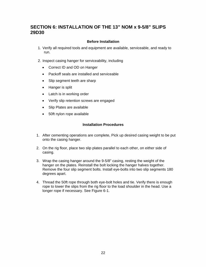
4. Thread the 50ft rope through both eye-bolt holes and tie. Verify there is enough rope to lower the slips from the rig floor to the load shoulder in the head. Use a longer rope if necessary. See Figure 6-1.
23
Figure 6-1
5. Using the rope, lower the slips through the BOPE until they land on the load
shoulder of the casing head. Once the slips have landed untie the rope and pull through the BOPE.
6. If the pipe is centered, the hanger will drop into the casing head bowl. If not, it will
be necessary to center the pipe using the Cat line and Air Tugger.
7. Slowly slack off casing weight, transferring the load to the slip hanger.
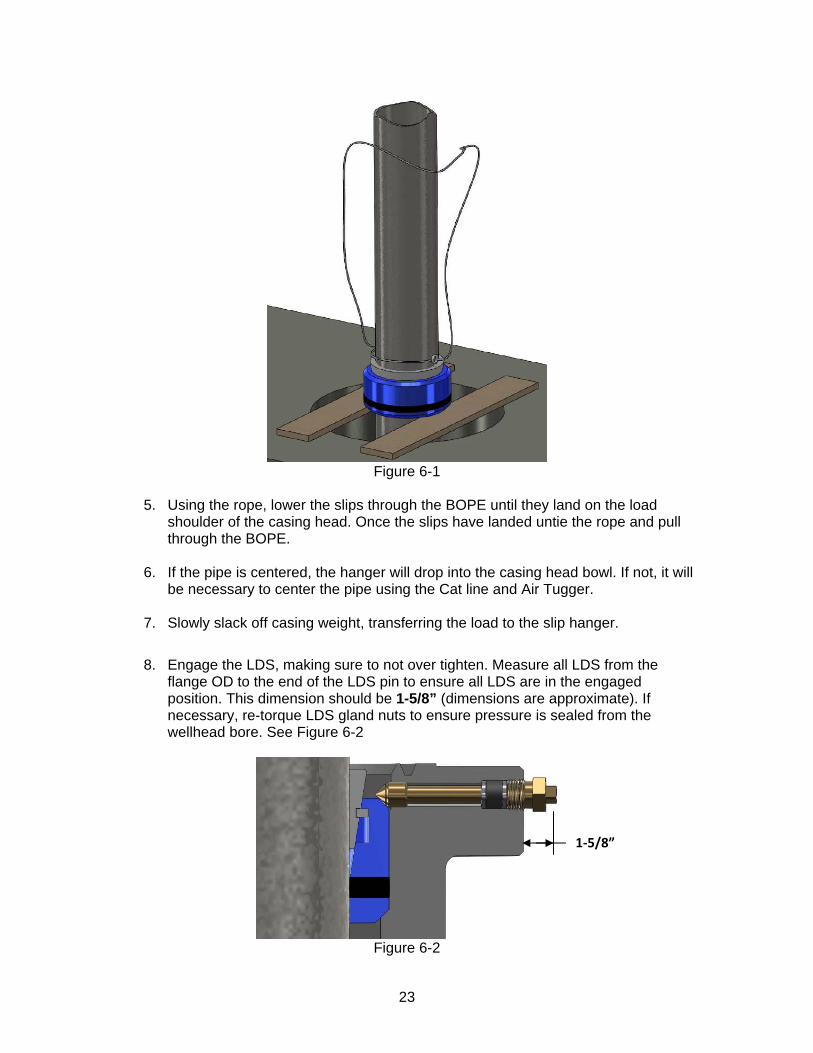
8. Engage the LDS, making sure to not over tighten. Measure all LDS from the
flange OD to the end of the LDS pin to ensure all LDS are in the engaged position. This dimension should be 1-5/8” (dimensions are approximate). If necessary, re-torque LDS gland nuts to ensure pressure is sealed from the wellhead bore. See Figure 6-2
Figure 6-2
1‐5/8”
24
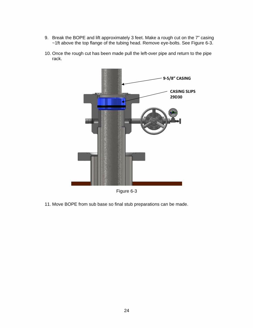
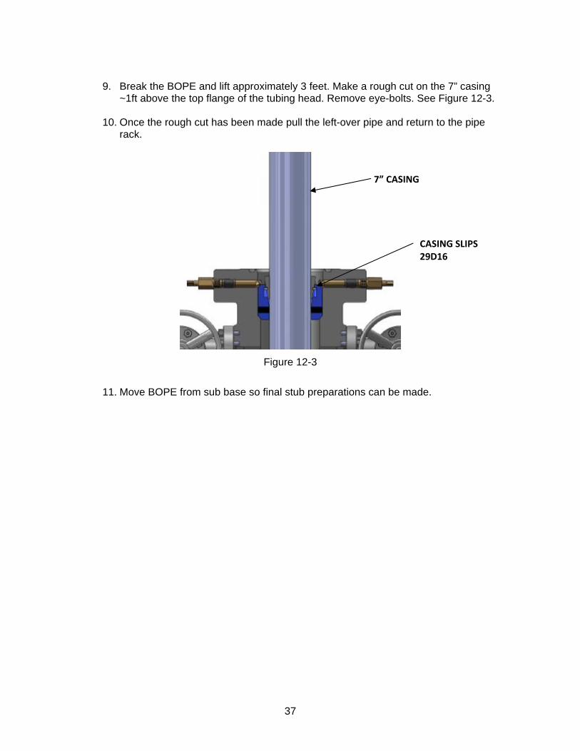
9. Break the BOPE and lift approximately 3 feet. Make a rough cut on the 7” casing
~1ft above the top flange of the tubing head. Remove eye-bolts. See Figure 6-3.
10. Once the rough cut has been made pull the left-over pipe and return to the pipe rack.
Figure 6-3
11. Move BOPE from sub base so final stub preparations can be made.
CASING SLIPS 29D30
9‐5/8” CASING
25
SECTION 7: 9-5/8” CASING STUB PREPARATION
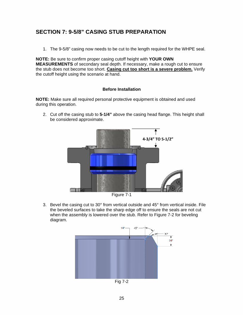
1. The 9-5/8” casing now needs to be cut to the length required for the WHPE seal.
NOTE: Be sure to confirm proper casing cutoff height with YOUR OWN MEASUREMENTS of secondary seal depth. If necessary, make a rough cut to ensure the stub does not become too short. Casing cut too short is a severe problem. Verify the cutoff height using the scenario at hand.
Before Installation NOTE: Make sure all required personal protective equipment is obtained and used during this operation.
2. Cut off the casing stub to 5-1/4” above the casing head flange. This height shall be considered approximate.
Figure 7-1
3. Bevel the casing cut to 30° from vertical outside and 45° from vertical inside. File
the beveled surfaces to take the sharp edge off to ensure the seals are not cut when the assembly is lowered over the stub. Refer to Figure 7-2 for beveling diagram.
Fig 7-2
4‐3/4” TO 5‐1/2”
26
SECTION 8: INSTALLATION OF THE 11” 10M x 13-5/8” 5M TUBING SPOOL 22C43 WITH WHPE SEAL 35W09
Before Installation NOTE: Make sure all required personal protective equipment is obtained and used during this operation.
1. Check and record the inventory code of the casing spool to ensure the proper equipment is on location. This code should be considered critical. The inventory code of the casing spool should be 22C43. This code is located on the first line of the stamp mark on the top flange after the name ELCO. Ex.: ELCO 22C43.
2. Check and record the through bore ID and bowl ID of the casing spool and re-verify size. The ID and bowl dimensions of the casing spool shall be considered critical. The through bore ID of the casing spool should not be less than 10” (in diameter and the bowl ID dimension should not be less than 10-7/8” in diameter (dimensions are approximate).
3. Ensure the WHPE secondary seal is properly installed. Apply a light coat of oil to
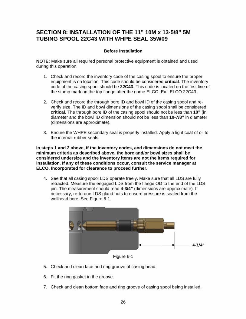
the internal rubber seals. In steps 1 and 2 above, if the inventory codes, and dimensions do not meet the minimum criteria as described above, the bore and/or bowl sizes shall be considered undersize and the inventory items are not the items required for installation. If any of these conditions occur, consult the service manager at ELCO, Incorporated for clearance to proceed further. 4. See that all casing spool LDS operate freely. Make sure that all LDS are fully
retracted. Measure the engaged LDS from the flange OD to the end of the LDS pin. The measurement should read 4-3/4” (dimensions are approximate). If necessary, re-torque LDS gland nuts to ensure pressure is sealed from the wellhead bore. See Figure 6-1.
Figure 6-1
5. Check and clean face and ring groove of casing head.
6. Fit the ring gasket in the groove.
7. Check and clean bottom face and ring groove of casing spool being installed.
4‐3/4”
27
8. Check that ring gasket fits groove in casing spool bottom face.
9. Check the side outlet (annulus) valves for free operation. Leave both valves open.
10. Make sure the correct number, size and type of studs and nuts are on hand. Oil
studs and nuts. 11. Ensure good communication with the rig floor. 12. Rig the spool for pick up using wire rope and clamps. WARNING: Never use hemp, nylon rope, chains, or any rigged or unauthorized lifting device to suspend or move wellhead equipment. Failure to use wire rope could result in dropping the wellhead equipment and causing severe injury to personnel.
Installation 1. Install the ring gasket on casing head. 2. Fill bowl of casing head with light oil. 3. Pick up the casing spool, ensuring that lift is level and safe. 4. Check that side outlet valves are in the proper orientation. 5. Install studs and nuts in flange through bolt holes below side outlet valves. NOTE: This must be done before spool is lowered onto casing head as clearance to install studs may not be available once equipment is brought together.
6. Lift spool over casing stub. Maintain side outlet valve orientation. WARNING: Do not put your hands on the casing while the tubing spool is being lowered onto the flange. 7. Lower spool slowly over the casing stub.
28
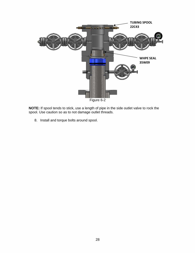
Figure 6-2
NOTE: If spool tends to stick, use a length of pipe in the side outlet valve to rock the spool. Use caution so as to not damage outlet threads. 8. Install and torque bolts around spool.
TUBING SPOOL 22C43
WHPE SEAL 35W09
29
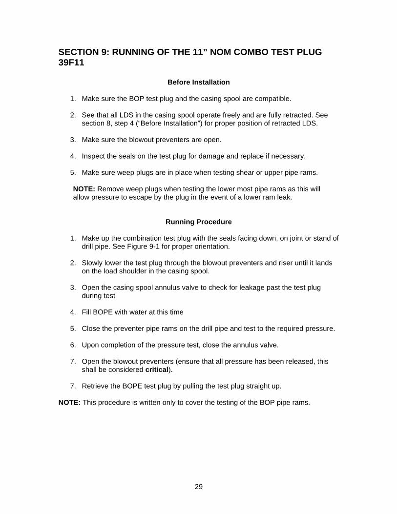
SECTION 9: RUNNING OF THE 11” NOM COMBO TEST PLUG 39F11
Before Installation 1. Make sure the BOP test plug and the casing spool are compatible. 2. See that all LDS in the casing spool operate freely and are fully retracted. See
section 8, step 4 (“Before Installation”) for proper position of retracted LDS. 3. Make sure the blowout preventers are open.
4. Inspect the seals on the test plug for damage and replace if necessary.
5. Make sure weep plugs are in place when testing shear or upper pipe rams.
NOTE: Remove weep plugs when testing the lower most pipe rams as this will allow pressure to escape by the plug in the event of a lower ram leak.
Running Procedure
1. Make up the combination test plug with the seals facing down, on joint or stand of drill pipe. See Figure 9-1 for proper orientation.
2. Slowly lower the test plug through the blowout preventers and riser until it lands
on the load shoulder in the casing spool.
3. Open the casing spool annulus valve to check for leakage past the test plug during test
4. Fill BOPE with water at this time 5. Close the preventer pipe rams on the drill pipe and test to the required pressure. 6. Upon completion of the pressure test, close the annulus valve. 7. Open the blowout preventers (ensure that all pressure has been released, this
shall be considered critical).
7. Retrieve the BOPE test plug by pulling the test plug straight up. NOTE: This procedure is written only to cover the testing of the BOP pipe rams.
30
Figure 9-1
BOP
COMBO TEST PLUG 39F11
LOAD SHOULDER
31
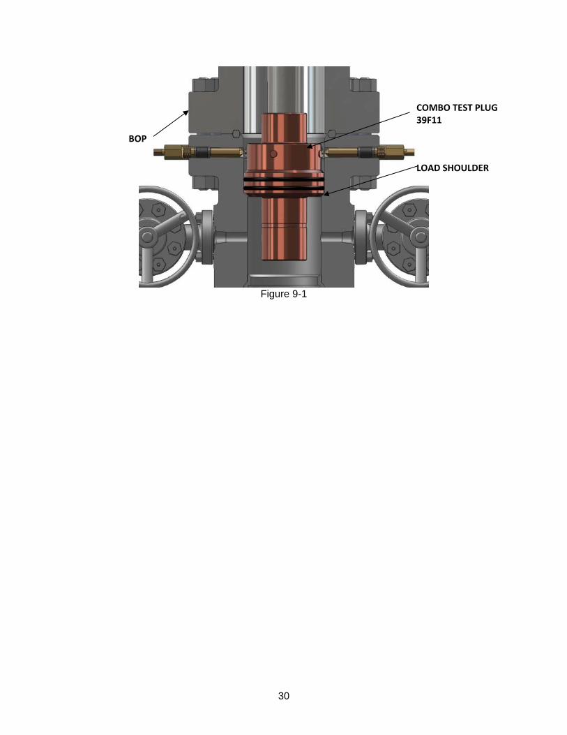
SECTION 10: INSTALLATION AND REMOVAL OF THE 11” WEAR BUSHING 38F29
Before Running 1. Make sure the bowl protector, running tool, and the casing spool are compatible. 2. Verify inside diameter of the bowl protector by drifting with the drill bit. The inside
diameter of the bowl protector should be no smaller than 9-15/16” in diameter (dimensions are approximate).
3. See that all LDS in the casing spool operate freely and are fully retracted. See
section 8, step 4 (“Before Installation”) for proper position of retracted LDS.
8. Make sure the blowout preventers are open.
9. Make sure running tool is compatible with the drill pipe that will be utilized to run in the wear bushing.
Running Procedure
7. Invert the running tool and make up the running tool with a joint or stand of drill pipe. See Figure 10-1 for proper orientation.
8. Stab the running tool into the bowl protector and rotate to the left, counter-
clockwise, 1/4 turn or until the tool shoulders out.
9. Pull the rotary bushing from the rotary table.
10. Lower the wear bushing through the blowout preventers and riser until it lands on the load shoulder of the casing head. Refer to Figure 10-1.
Figure 10-1
BOP
WEAR BUSHING 38F29
COMBO TEST PLUG 39F11
LOAD SHOULDER
32
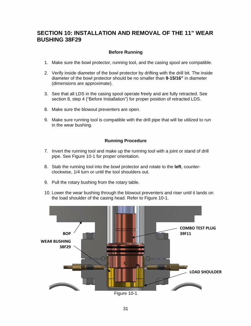
11. Engage the two LDS, making sure to not over tighten. If over tightened, damage could occur to the wear bushing. Measure all LDS from the flange OD to the end of the LDS pin to ensure all LDS are in the engaged position. This dimension should be 4-1/2” (dimensions are approximate). If necessary, re-torque LDS gland nuts to ensure pressure is sealed from the wellhead bore. See Figure 10-2
Figure 10-2
10. Rotate the drill string to the right, clockwise, 1/4 turn or until the running tool shoulders out.
11. Pull the running tool straight up. The bowl protector is now secure in the casing
head and drilling may resume. NOTE: ELCO recommends that all bowl protectors be pulled and visually inspected for wear at least once after every full trip of the drill pipe. If the bowl protector appears to be wearing quickly or abnormally, ELCO recommends that a qualified ELCO service representative be consulted to determine further actions.
4‐1/2”
33
Retrieval Procedures
1. Make up the running tool and a joint or stand of drill pipe. Refer to Figure 10-1 for orientation.
2. Pull the rotary bushing from the rotary table. 3. Slowly lower the running tool through the blowout preventers and riser until it
lands on the wear bushing. 4. Rotate the drill pipe to the left, counter-clockwise, until the string drops. 5. Rotate the drill string to the left 1/4 turn or until the running tool shoulders out. 6. Retract the LDS that were previously engaged. See section 8, step 2 (“Before
Installation”) for proper position of retracted LDS. 7. Pull straight up on the bowl protector and retrieve.
34
SECTION 11: RUNNING OF THE WASHOUT TOOL 25J10
Before Running Tool
1. Verify all required tools and equipment are available, serviceable and ready to run.
Running Procedure
2. Make up a stand of drill pipe with 4 ½” IF (NC50) male threads into the 4 ½” IF
(NC50) female threads on the Washout Tool.
3. Open casing spool annular gate valve for drainage.
4. Slowly lower the Washout Tool into the BOPE. Turn the pump on to a flow rate of 3-4 barrels per minute and let it run for a minimum of 15 minutes. As the pump runs, slowly rotate washout tool at a rate of approximately 1-2 RPM.
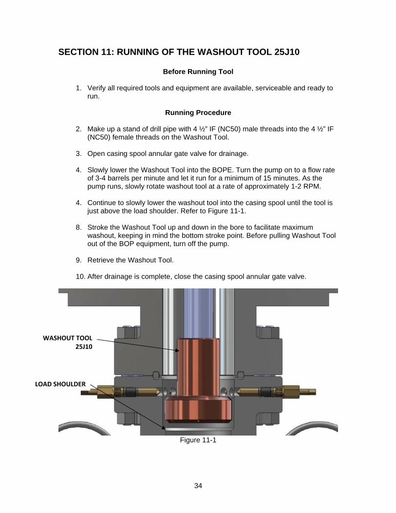
4. Continue to slowly lower the washout tool into the casing spool until the tool is
just above the load shoulder. Refer to Figure 11-1.
8. Stroke the Washout Tool up and down in the bore to facilitate maximum washout, keeping in mind the bottom stroke point. Before pulling Washout Tool out of the BOP equipment, turn off the pump.
9. Retrieve the Washout Tool.
10. After drainage is complete, close the casing spool annular gate valve.
Figure 11-1
WASHOUT TOOL 25J10
LOAD SHOULDER
35
SECTION 12: INSTALLATION OF THE 11” NOM x 7” SLIPS 29D16
Before Installation
2. Verify all required tools and equipment are available, serviceable, and ready to run.
2. Inspect casing hanger for serviceability, including
Correct ID and OD on Hanger
Packoff seals are installed and serviceable
Slip segment teeth are sharp
Hanger is split
Latch is in working order
Verify slip retention screws are engaged
Slip Plates are available
50ft nylon rope available
Installation Procedures
1. After cementing operations are complete, Pick up desired casing weight to be put
onto the casing hanger.
2. On the rig floor, place two slip plates parallel to each other, on either side of casing.
3. Wrap the casing hanger around the 7” casing, resting the weight of the hanger on the plates. Reinstall the bolt locking the hanger halves together. Remove the four slip segment bolts. Install eye-bolts into two slip segments 180 degrees apart.
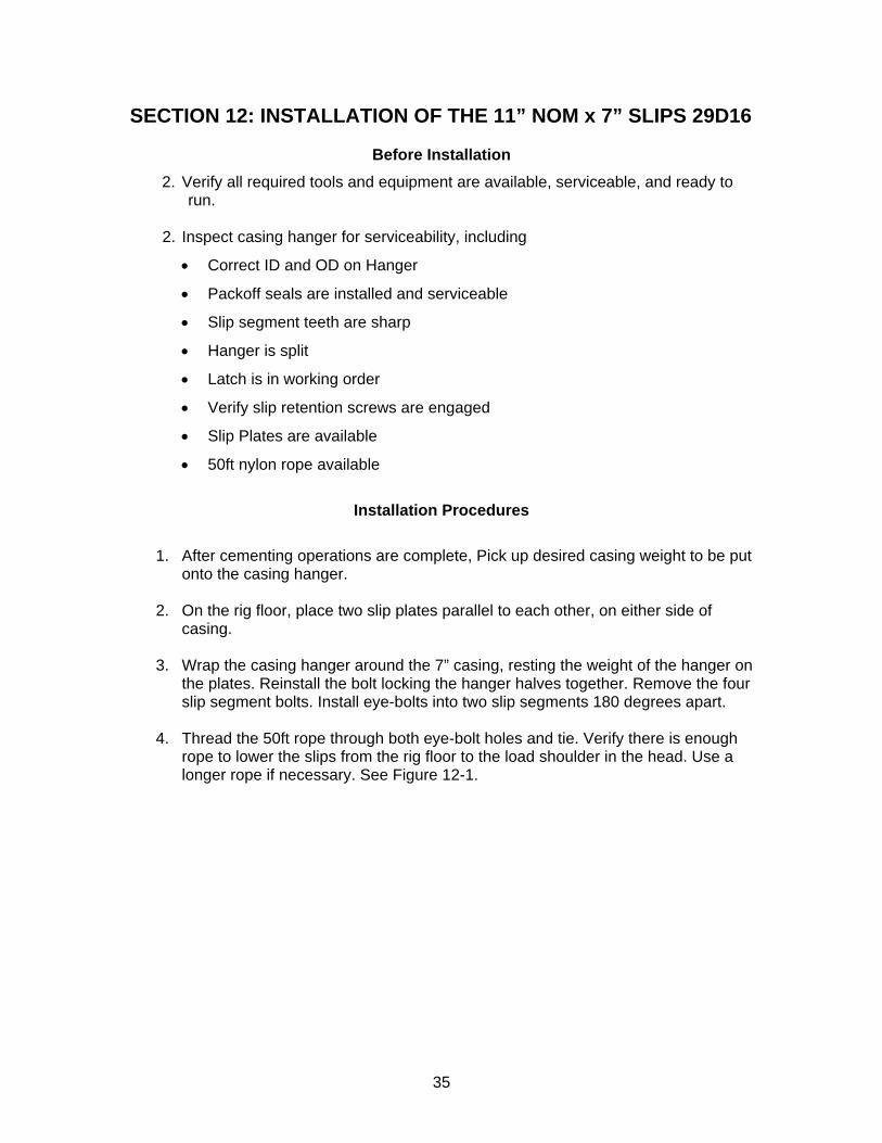
4. Thread the 50ft rope through both eye-bolt holes and tie. Verify there is enough rope to lower the slips from the rig floor to the load shoulder in the head. Use a longer rope if necessary. See Figure 12-1.
36
Figure 12-1
5. Using the rope, lower the slips through the BOPE until they land on the load
shoulder of the casing head. Once the slips have landed, untie the rope and pull out through the BOPE.
6. If the pipe is centered, the hanger will drop into the casing head bowl. If not, it will
be necessary to center the pipe using the Cat line and Air Tugger.
7. Slowly slack off casing weight, transferring the load to the slip hanger.
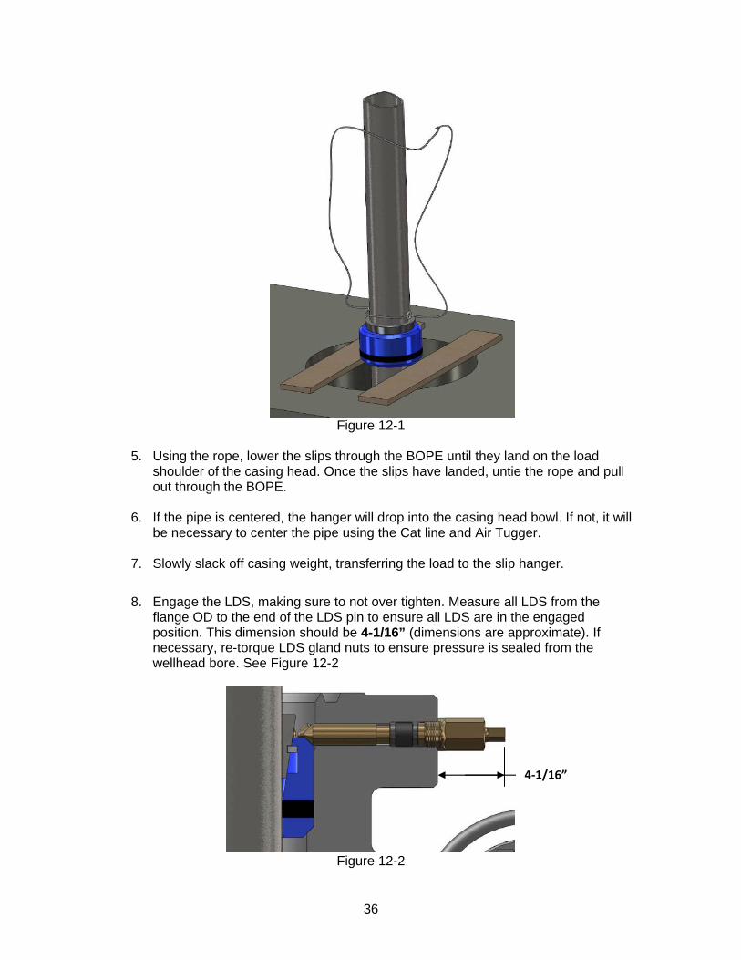
8. Engage the LDS, making sure to not over tighten. Measure all LDS from the
flange OD to the end of the LDS pin to ensure all LDS are in the engaged position. This dimension should be 4-1/16” (dimensions are approximate). If necessary, re-torque LDS gland nuts to ensure pressure is sealed from the wellhead bore. See Figure 12-2
Figure 12-2
4‐1/16”
37
9. Break the BOPE and lift approximately 3 feet. Make a rough cut on the 7” casing
~1ft above the top flange of the tubing head. Remove eye-bolts. See Figure 12-3.
10. Once the rough cut has been made pull the left-over pipe and return to the pipe rack.
Figure 12-3
11. Move BOPE from sub base so final stub preparations can be made.
CASING SLIPS 29D16
7” CASING
38
SECTION 13: 7” CASING STUB PREPARATION
1. The 7” casing now needs to be cut to the length required for the WHPE seal.
NOTE: Be sure to confirm proper casing cutoff height with YOUR OWN MEASUREMENTS of secondary seal depth. If necessary, make a rough cut to ensure the stub does not become too short. Casing cut too short is a severe problem. Verify the cutoff height using the scenario at hand.
Before Installation NOTE: Make sure all required personal protective equipment is obtained and used during this operation.
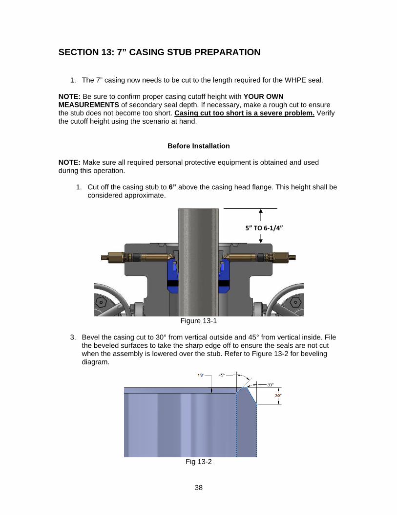
1. Cut off the casing stub to 6” above the casing head flange. This height shall be considered approximate.
Figure 13-1
3. Bevel the casing cut to 30° from vertical outside and 45° from vertical inside. File
the beveled surfaces to take the sharp edge off to ensure the seals are not cut when the assembly is lowered over the stub. Refer to Figure 13-2 for beveling diagram.
Fig 13-2
5” TO 6‐1/4”
39
SECTION 14: INSTALLATION OF THE 11” 10M x 11” 10M TUBING SPOOL 32K24 WITH WHPE SEAL 35W07
Before Installation NOTE: Make sure all required personal protective equipment is obtained and used during this operation.
1. Check and record the inventory code of the tubing spool to ensure the proper equipment is on location. This code should be considered critical. The inventory code of the tubing spool should be 32K24. This code is located on the first line of the stamp mark on the top flange after the name ELCO. Ex.: ELCO 32K24.
2. Check and record the through bore ID and bowl ID of the tubing spool and re-verify size. The ID and bowl dimensions of the tubing spool shall be considered critical. The through bore ID of the tubing spool should not be less than 8-1/2” in diameter and the bowl ID dimension should not be less than 10-7/8” in diameter (dimensions are approximate).
3. Ensure the WHPE secondary seal is properly installed. Apply a light coat of oil to
the internal rubber seals. In steps 1 and 2 above, if the inventory codes, and dimensions do not meet the minimum criteria as described above, the bore and/or bowl sizes shall be considered undersize and the inventory items are not the items required for installation. If any of these conditions occur, consult the service manager at ELCO, Incorporated for clearance to proceed further. 4. See that all LDS in the casing spool operate freely and are fully retracted. See
section 8, step 4 (“Before Installation”) for proper position of retracted LDS. 5. Check and clean face and ring groove of casing spool.
6. Fit the ring gasket in the groove.
7. Check and clean bottom face and ring groove of tubing spool being installed. 8. Check that ring gasket fits groove in tubing spool bottom face.
9. Check the side outlet (annulus) valves for free operation. Leave both valves
open.
10. Remove 1/2" plug from test port in bottom flange of spool and blow air through port.
11. Ensure good communication with the rig floor. 12. Rig the spool for pick up using wire rope and clamps.
40
WARNING: Never use hemp, nylon rope, chains, or any rigged or unauthorized lifting device to suspend or move wellhead equipment. Failure to use wire rope could result in dropping the wellhead equipment and causing severe injury to personnel.
Installation 1. Install the ring gasket on casing spool. 2. Fill bowl of casing spool with light oil. 3. Pick up the tubing spool, ensuring that lift is level and safe. 4. Check that side outlet valves are in the proper orientation. 5. Install studs and nuts in flange through bolt holes below side outlet valves. NOTE: This must be done before the tubing spool is lowered onto the casing spool as clearance to install studs may not be available once spools are brought together.
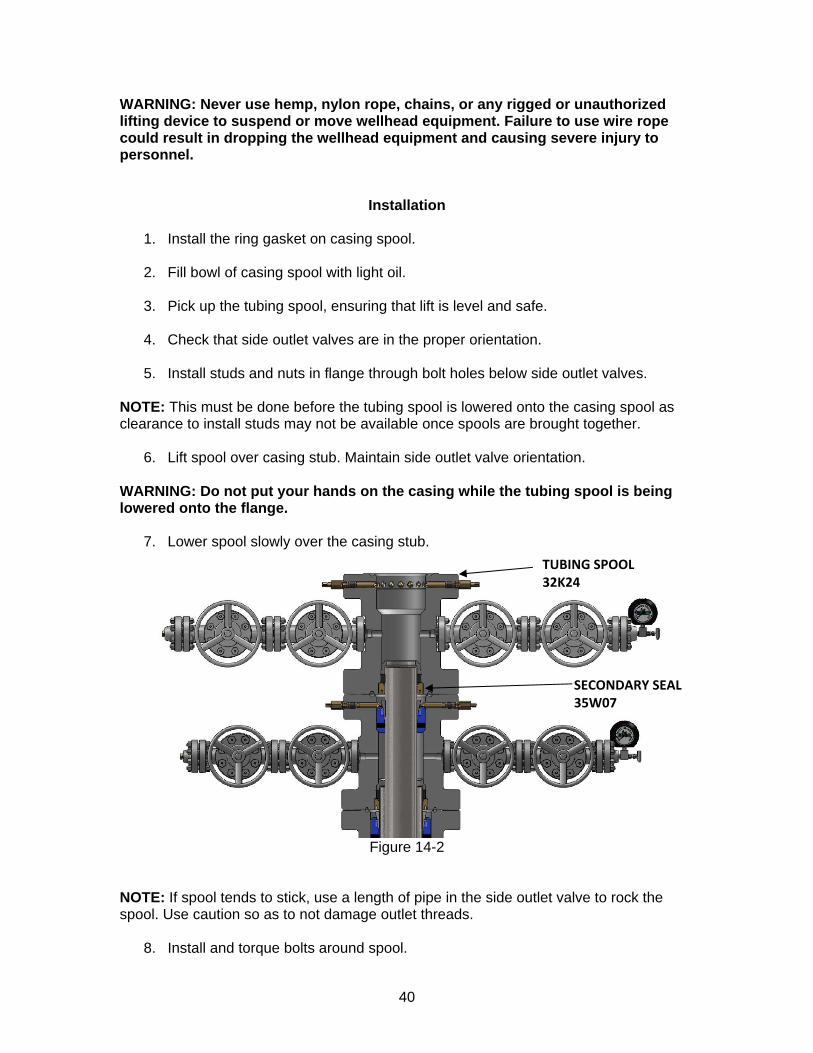
6. Lift spool over casing stub. Maintain side outlet valve orientation. WARNING: Do not put your hands on the casing while the tubing spool is being lowered onto the flange. 7. Lower spool slowly over the casing stub.
Figure 14-2
NOTE: If spool tends to stick, use a length of pipe in the side outlet valve to rock the spool. Use caution so as to not damage outlet threads. 8. Install and torque bolts around spool.
TUBING SPOOL 32K24
SECONDARY SEAL 35W07
41
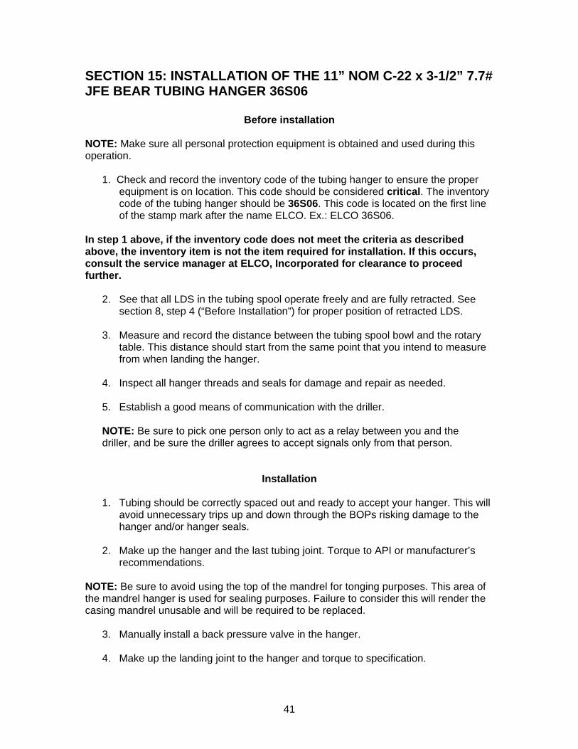
SECTION 15: INSTALLATION OF THE 11” NOM C-22 x 3-1/2” 7.7# JFE BEAR TUBING HANGER 36S06
Before installation NOTE: Make sure all personal protection equipment is obtained and used during this operation. 1. Check and record the inventory code of the tubing hanger to ensure the proper
equipment is on location. This code should be considered critical. The inventory code of the tubing hanger should be 36S06. This code is located on the first line of the stamp mark after the name ELCO. Ex.: ELCO 36S06.
In step 1 above, if the inventory code does not meet the criteria as described above, the inventory item is not the item required for installation. If this occurs, consult the service manager at ELCO, Incorporated for clearance to proceed further.
2. See that all LDS in the tubing spool operate freely and are fully retracted. See section 8, step 4 (“Before Installation”) for proper position of retracted LDS.
3. Measure and record the distance between the tubing spool bowl and the rotary
table. This distance should start from the same point that you intend to measure from when landing the hanger.
4. Inspect all hanger threads and seals for damage and repair as needed.
5. Establish a good means of communication with the driller.
NOTE: Be sure to pick one person only to act as a relay between you and the driller, and be sure the driller agrees to accept signals only from that person.
Installation
1. Tubing should be correctly spaced out and ready to accept your hanger. This will avoid unnecessary trips up and down through the BOPs risking damage to the hanger and/or hanger seals.
2. Make up the hanger and the last tubing joint. Torque to API or manufacturer’s
recommendations. NOTE: Be sure to avoid using the top of the mandrel for tonging purposes. This area of the mandrel hanger is used for sealing purposes. Failure to consider this will render the casing mandrel unusable and will be required to be replaced.
3. Manually install a back pressure valve in the hanger.
4. Make up the landing joint to the hanger and torque to specification.
42
5. Grease the body of the hanger
6. Drain the BOP stack through the tubing spool annulus valves.
7. Wash out the BOP stack with compatible well fluids to dislodge any cuttings or foreign materials.
8. Slowly lower the hanger and tubing through the blowout preventers and riser. Measure and mark the tubing while it descends in the BOPs.
9. As you approach the landing shoulder in the spool, have the driller slow the decent to a minimum.
10. Make a mark on the landing joint that will align with the rotary table just as the hanger stops on the landing shoulder in the spool.
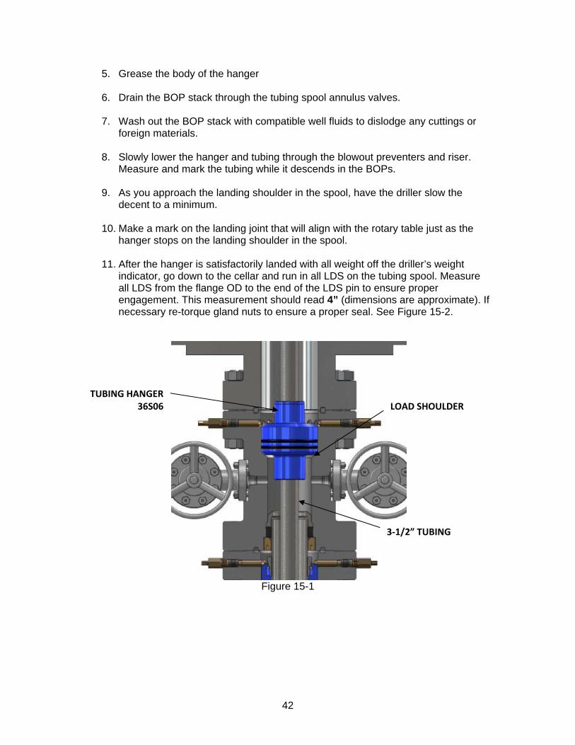
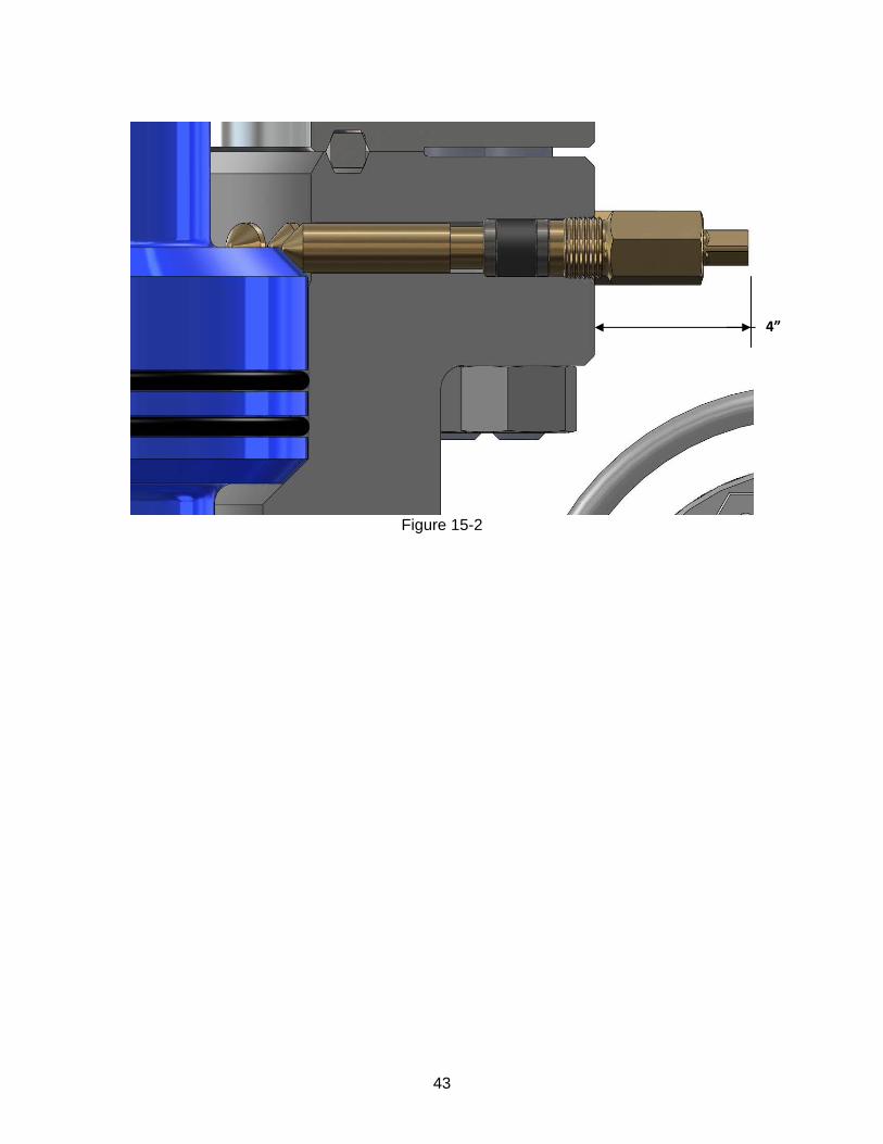
11. After the hanger is satisfactorily landed with all weight off the driller’s weight indicator, go down to the cellar and run in all LDS on the tubing spool. Measure all LDS from the flange OD to the end of the LDS pin to ensure proper engagement. This measurement should read 4” (dimensions are approximate). If necessary re-torque gland nuts to ensure a proper seal. See Figure 15-2.
Figure 15-1
TUBING HANGER 36S06
3‐1/2” TUBING
LOAD SHOULDER
43
Figure 15-2
4”
44
SECTION 16: INSTALLATION OF THE 11” 10M x 3-1/16” 10M TREE ASSEMBLY
Before installation NOTE: Make sure all personal protection equipment is obtained and used during this operation.
1. Check and record the inventory code of the tubing head adapter to ensure the proper equipment is on location. This code should be considered critical. The inventory code of the tubing head adapter should be 41A33. This code is located on the first line of the stamp mark on the body of the tubing head adapter after the name ELCO. Ex.: ELCO 41A33.
2. Check and record the inventory code of the MMS (Metal to Metal Seal) to ensure the proper equipment is on location. This code should be considered critical. The inventory code should be 62018. This code is located on the first line of the engraved mark on the OD of the seal after the name ELCO. Ex.: ELCO 62018.
3. Caliper and record the neck OD of the tubing hanger and make sure this dimension is not more than the ID of the tubing head adapter pocket. This OD and ID combination shall be considered critical. The tubing hanger OD should not be more than 5-3/4” in diameter. The ID of the adapter should not be less than 5-13/16” in diameter (dimensions are approximate).
In steps 1, 2, and 3 above, if the inventory code and ID/OD dimensions do not meet the criteria as described above, the bore size shall be considered under/over-sized and the inventory item is not the item required for installation. If any of these conditions occur, consult the service manager at ELCO, Incorporated for clearance to proceed further.
4. Always verify that each gate valve in the tree is operating correctly by operating
each valve while counting for correct turns.
5. Check all test ports to assure they are clear by attaching a test pump and pumping fresh clean fluid through.
Installation
1. Open all valves on the christmas tree.
2. Make sure you have the correct studs, nuts and ring gaskets for the christmas tree nipple up.
3. Ensure the adapter seal bore and tubing hanger are clean and lubricated. Inspect the adapter O-ring seal for damage and replace if necessary. Install the MMS seal in the tubing hanger seal prep at this time.
45
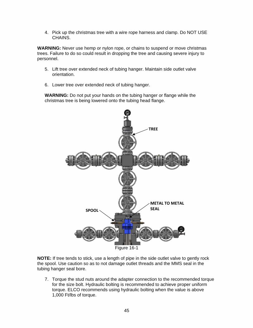
4. Pick up the christmas tree with a wire rope harness and clamp. Do NOT USE CHAINS.
WARNING: Never use hemp or nylon rope, or chains to suspend or move christmas trees. Failure to do so could result in dropping the tree and causing severe injury to personnel.
5. Lift tree over extended neck of tubing hanger. Maintain side outlet valve
orientation.
6. Lower tree over extended neck of tubing hanger.
WARNING: Do not put your hands on the tubing hanger or flange while the christmas tree is being lowered onto the tubing head flange.
Figure 16-1
NOTE: If tree tends to stick, use a length of pipe in the side outlet valve to gently rock the spool. Use caution so as to not damage outlet threads and the MMS seal in the tubing hanger seal bore.
7. Torque the stud nuts around the adapter connection to the recommended torque for the size bolt. Hydraulic bolting is recommended to achieve proper uniform torque. ELCO recommends using hydraulic bolting when the value is above 1,000 Ft/lbs of torque.
TREE
METAL TO METAL SEAL SPOOL
46
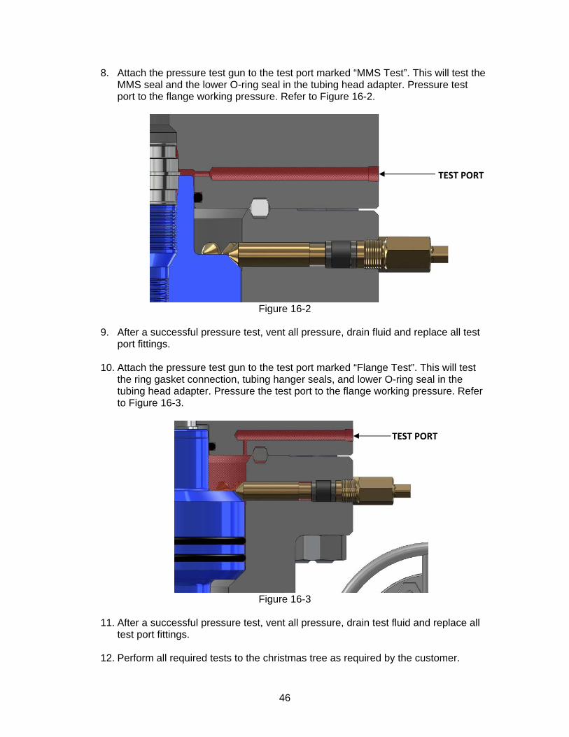
8. Attach the pressure test gun to the test port marked “MMS Test”. This will test the MMS seal and the lower O-ring seal in the tubing head adapter. Pressure test port to the flange working pressure. Refer to Figure 16-2.
Figure 16-2
9. After a successful pressure test, vent all pressure, drain fluid and replace all test
port fittings.
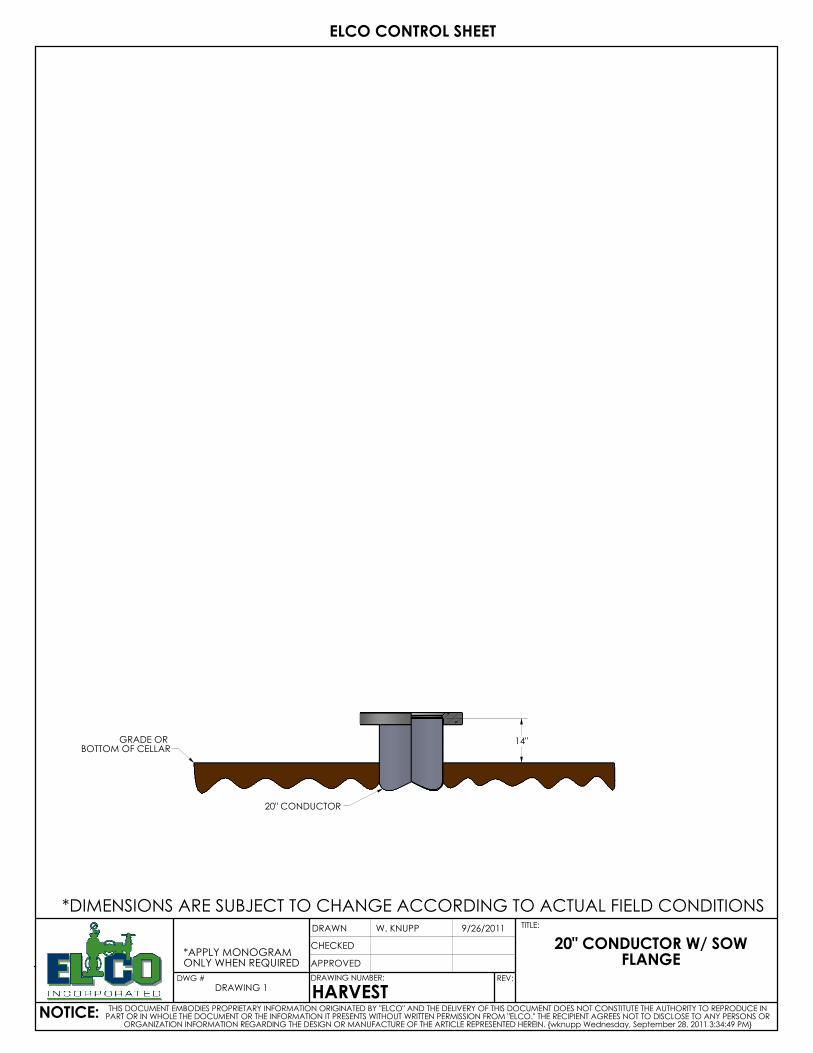
10. Attach the pressure test gun to the test port marked “Flange Test”. This will test the ring gasket connection, tubing hanger seals, and lower O-ring seal in the tubing head adapter. Pressure the test port to the flange working pressure. Refer to Figure 16-3.
Figure 16-3
11. After a successful pressure test, vent all pressure, drain test fluid and replace all
test port fittings.
12. Perform all required tests to the christmas tree as required by the customer.
TEST PORT
TEST PORT

47
SECTION 17: SEQUENTIAL DRAWINGS
GRADE OR BOTTOM OF CELLAR
20" CONDUCTOR
14"
*APPLY MONOGRAMONLY WHEN REQUIRED
DRAWING 1
ELCO CONTROL SHEET
9/26/2011
CHECKED
APPROVED
W. KNUPP
NOTICE:
20" CONDUCTOR W/ SOW FLANGE
TITLE:
THIS DOCUMENT EMBODIES PROPRIETARY INFORMATION ORIGINATED BY "ELCO" AND THE DELIVERY OF THIS DOCUMENT DOES NOT CONSTITUTE THE AUTHORITY TO REPRODUCE IN PART OR IN WHOLE THE DOCUMENT OR THE INFORMATION IT PRESENTS WITHOUT WRITTEN PERMISSION FROM "ELCO." THE RECIPIENT AGREES NOT TO DISCLOSE TO ANY PERSONS OR
ORGANIZATION INFORMATION REGARDING THE DESIGN OR MANUFACTURE OF THE ARTICLE REPRESENTED HEREIN. {wknupp Wednesday, September 28, 2011 3:34:49 PM}
DRAWING NUMBER:
HARVEST
DRAWN
DWG # REV:
*DIMENSIONS ARE SUBJECT TO CHANGE ACCORDING TO ACTUAL FIELD CONDITIONS
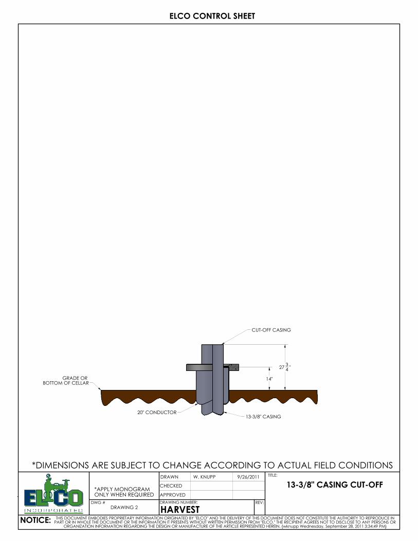
GRADE OR BOTTOM OF CELLAR
20" CONDUCTOR13-3/8" CASING
CUT-OFF CASING
14"
2734 "
*DIMENSIONS ARE SUBJECT TO CHANGE ACCORDING TO ACTUAL FIELD CONDITIONS
*APPLY MONOGRAMONLY WHEN REQUIRED
DRAWING 2
ELCO CONTROL SHEET
9/26/2011
CHECKED
APPROVED
W. KNUPP
NOTICE:
13-3/8" CASING CUT-OFF
TITLE:
THIS DOCUMENT EMBODIES PROPRIETARY INFORMATION ORIGINATED BY "ELCO" AND THE DELIVERY OF THIS DOCUMENT DOES NOT CONSTITUTE THE AUTHORITY TO REPRODUCE IN PART OR IN WHOLE THE DOCUMENT OR THE INFORMATION IT PRESENTS WITHOUT WRITTEN PERMISSION FROM "ELCO." THE RECIPIENT AGREES NOT TO DISCLOSE TO ANY PERSONS OR
ORGANIZATION INFORMATION REGARDING THE DESIGN OR MANUFACTURE OF THE ARTICLE REPRESENTED HEREIN. {wknupp Wednesday, September 28, 2011 3:34:49 PM}
DRAWING NUMBER:
HARVEST
DRAWN
DWG # REV:
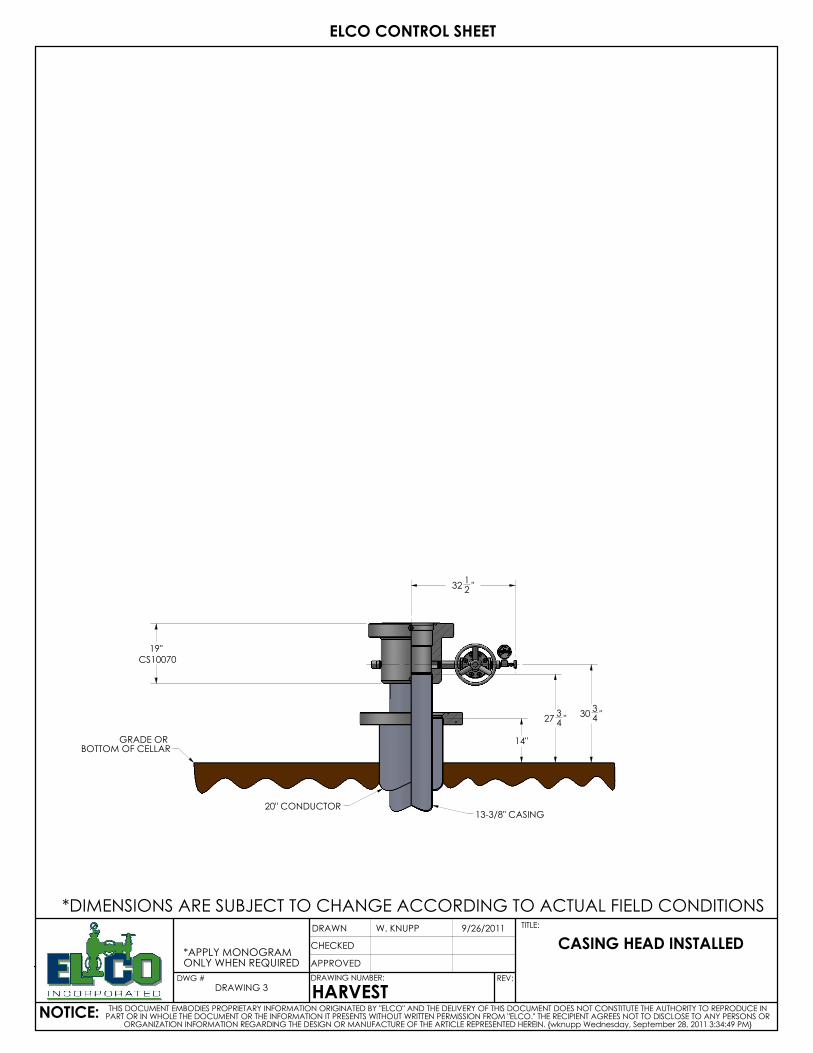
GRADE OR BOTTOM OF CELLAR
20" CONDUCTOR13-3/8" CASING
19"CS10070
3034 "
14"
3212 "
2734 "
*APPLY MONOGRAMONLY WHEN REQUIRED
DRAWING 3
ELCO CONTROL SHEET
9/26/2011
CHECKED
APPROVED
W. KNUPP
NOTICE:
CASING HEAD INSTALLED
TITLE:
THIS DOCUMENT EMBODIES PROPRIETARY INFORMATION ORIGINATED BY "ELCO" AND THE DELIVERY OF THIS DOCUMENT DOES NOT CONSTITUTE THE AUTHORITY TO REPRODUCE IN PART OR IN WHOLE THE DOCUMENT OR THE INFORMATION IT PRESENTS WITHOUT WRITTEN PERMISSION FROM "ELCO." THE RECIPIENT AGREES NOT TO DISCLOSE TO ANY PERSONS OR
ORGANIZATION INFORMATION REGARDING THE DESIGN OR MANUFACTURE OF THE ARTICLE REPRESENTED HEREIN. {wknupp Wednesday, September 28, 2011 3:34:49 PM}
DRAWING NUMBER:
HARVEST
DRAWN
DWG # REV:
*DIMENSIONS ARE SUBJECT TO CHANGE ACCORDING TO ACTUAL FIELD CONDITIONS
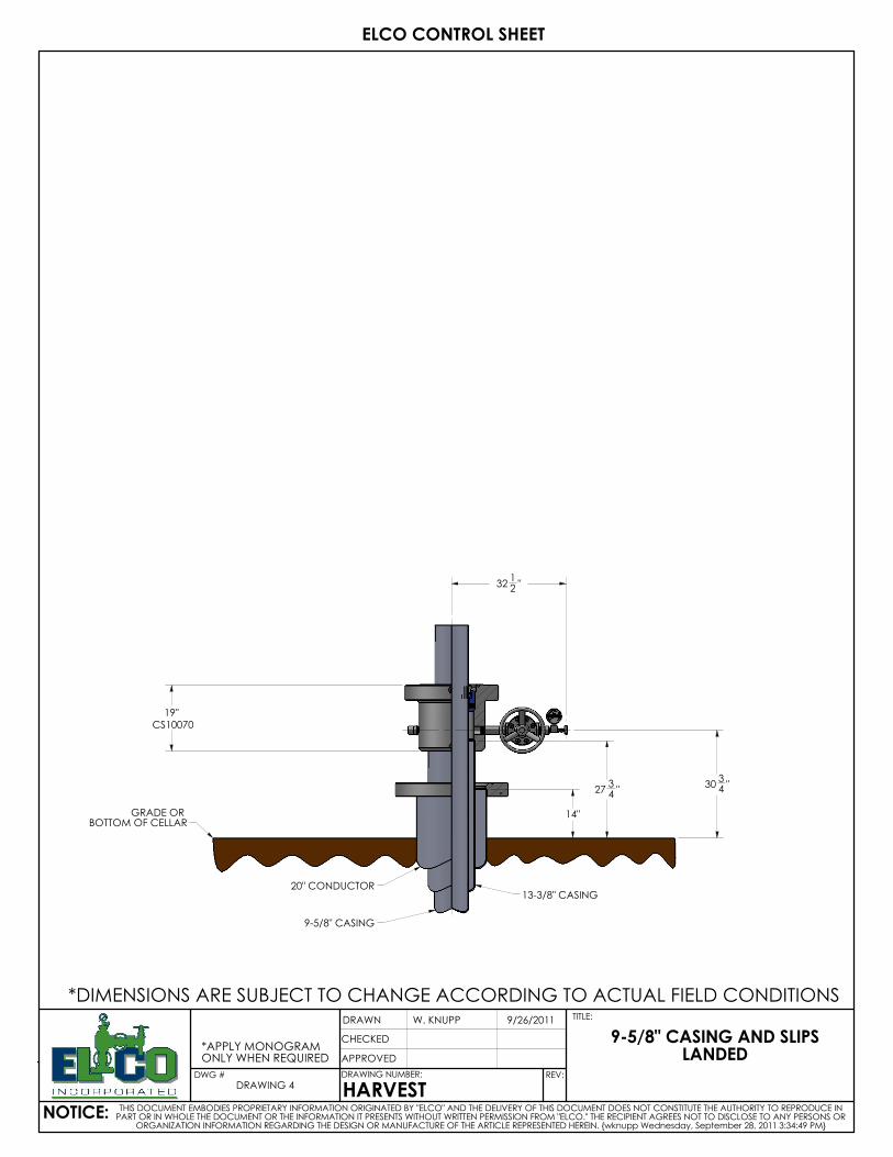
GRADE OR BOTTOM OF CELLAR
20" CONDUCTOR13-3/8" CASING
9-5/8" CASING
19"CS10070
3034 "
14"
3212 "
2734 "
*DIMENSIONS ARE SUBJECT TO CHANGE ACCORDING TO ACTUAL FIELD CONDITIONS
*APPLY MONOGRAMONLY WHEN REQUIRED
DRAWING 4
ELCO CONTROL SHEET
9/26/2011
CHECKED
APPROVED
W. KNUPP
NOTICE:
9-5/8" CASING AND SLIPS LANDED
TITLE:
THIS DOCUMENT EMBODIES PROPRIETARY INFORMATION ORIGINATED BY "ELCO" AND THE DELIVERY OF THIS DOCUMENT DOES NOT CONSTITUTE THE AUTHORITY TO REPRODUCE IN PART OR IN WHOLE THE DOCUMENT OR THE INFORMATION IT PRESENTS WITHOUT WRITTEN PERMISSION FROM "ELCO." THE RECIPIENT AGREES NOT TO DISCLOSE TO ANY PERSONS OR
ORGANIZATION INFORMATION REGARDING THE DESIGN OR MANUFACTURE OF THE ARTICLE REPRESENTED HEREIN. {wknupp Wednesday, September 28, 2011 3:34:49 PM}
DRAWING NUMBER:
HARVEST
DRAWN
DWG # REV:
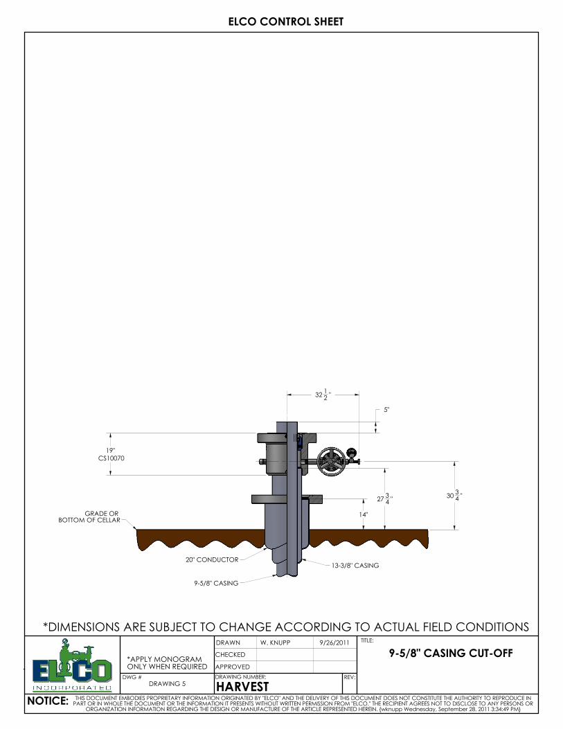
GRADE OR BOTTOM OF CELLAR
20" CONDUCTOR13-3/8" CASING
9-5/8" CASING
19"
CS10070
3034 "
14"
5"
3212 "
2734 "
*APPLY MONOGRAMONLY WHEN REQUIRED
DRAWING 5
ELCO CONTROL SHEET
9/26/2011
CHECKED
APPROVED
W. KNUPP
NOTICE:
9-5/8" CASING CUT-OFF
TITLE:
THIS DOCUMENT EMBODIES PROPRIETARY INFORMATION ORIGINATED BY "ELCO" AND THE DELIVERY OF THIS DOCUMENT DOES NOT CONSTITUTE THE AUTHORITY TO REPRODUCE IN PART OR IN WHOLE THE DOCUMENT OR THE INFORMATION IT PRESENTS WITHOUT WRITTEN PERMISSION FROM "ELCO." THE RECIPIENT AGREES NOT TO DISCLOSE TO ANY PERSONS OR
ORGANIZATION INFORMATION REGARDING THE DESIGN OR MANUFACTURE OF THE ARTICLE REPRESENTED HEREIN. {wknupp Wednesday, September 28, 2011 3:34:49 PM}
DRAWING NUMBER:
HARVEST
DRAWN
DWG # REV:
*DIMENSIONS ARE SUBJECT TO CHANGE ACCORDING TO ACTUAL FIELD CONDITIONS
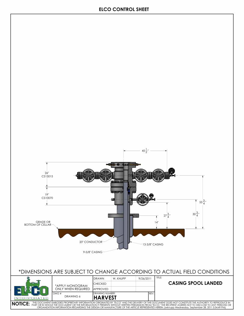
GRADE OR BOTTOM OF CELLAR
20" CONDUCTOR13-3/8" CASING
9-5/8" CASING
19"CS10070
26"
CS15015
3034 "
5534 "
14"
4512 "
2734 "
*DIMENSIONS ARE SUBJECT TO CHANGE ACCORDING TO ACTUAL FIELD CONDITIONS
*APPLY MONOGRAMONLY WHEN REQUIRED
DRAWING 6
ELCO CONTROL SHEET
9/26/2011
CHECKED
APPROVED
W. KNUPP
NOTICE:
CASING SPOOL LANDED
TITLE:
THIS DOCUMENT EMBODIES PROPRIETARY INFORMATION ORIGINATED BY "ELCO" AND THE DELIVERY OF THIS DOCUMENT DOES NOT CONSTITUTE THE AUTHORITY TO REPRODUCE IN PART OR IN WHOLE THE DOCUMENT OR THE INFORMATION IT PRESENTS WITHOUT WRITTEN PERMISSION FROM "ELCO." THE RECIPIENT AGREES NOT TO DISCLOSE TO ANY PERSONS OR
ORGANIZATION INFORMATION REGARDING THE DESIGN OR MANUFACTURE OF THE ARTICLE REPRESENTED HEREIN. {wknupp Wednesday, September 28, 2011 3:34:49 PM}
DRAWING NUMBER:
HARVEST
DRAWN
DWG # REV:
GRADE OR BOTTOM OF CELLAR
20" CONDUCTOR13-3/8" CASING
9-5/8" CASING
7" CASING
19"CS10070
26"
CS15015
3034 "
5534 "
14"
4512 "
2734 "
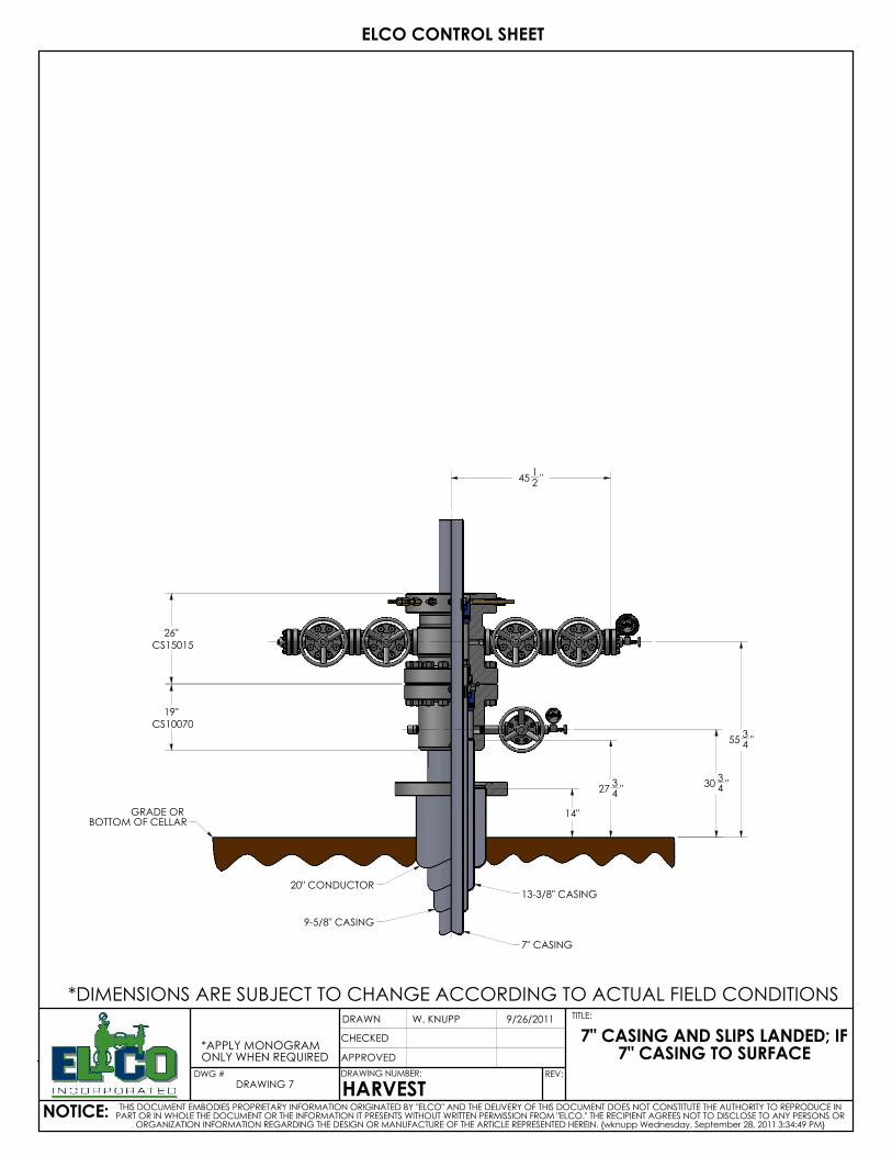
*APPLY MONOGRAMONLY WHEN REQUIRED
DRAWING 7
ELCO CONTROL SHEET
9/26/2011
CHECKED
APPROVED
W. KNUPP
NOTICE:
7" CASING AND SLIPS LANDED; IF 7" CASING TO SURFACE
TITLE:
THIS DOCUMENT EMBODIES PROPRIETARY INFORMATION ORIGINATED BY "ELCO" AND THE DELIVERY OF THIS DOCUMENT DOES NOT CONSTITUTE THE AUTHORITY TO REPRODUCE IN PART OR IN WHOLE THE DOCUMENT OR THE INFORMATION IT PRESENTS WITHOUT WRITTEN PERMISSION FROM "ELCO." THE RECIPIENT AGREES NOT TO DISCLOSE TO ANY PERSONS OR
ORGANIZATION INFORMATION REGARDING THE DESIGN OR MANUFACTURE OF THE ARTICLE REPRESENTED HEREIN. {wknupp Wednesday, September 28, 2011 3:34:49 PM}
DRAWING NUMBER:
HARVEST
DRAWN
DWG # REV:
*DIMENSIONS ARE SUBJECT TO CHANGE ACCORDING TO ACTUAL FIELD CONDITIONS
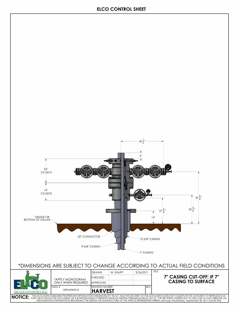
GRADE OR BOTTOM OF CELLAR
20" CONDUCTOR13-3/8" CASING
9-5/8" CASING
7" CASING
19"CS10070
26"
CS15015
3034 "
5534 "
14"
4512 "
6"
2734 "
*DIMENSIONS ARE SUBJECT TO CHANGE ACCORDING TO ACTUAL FIELD CONDITIONS
*APPLY MONOGRAMONLY WHEN REQUIRED
DRAWING 8
ELCO CONTROL SHEET
9/26/2011
CHECKED
APPROVED
W. KNUPP
NOTICE:
7" CASING CUT-OFF; IF 7" CASING TO SURFACE
TITLE:
THIS DOCUMENT EMBODIES PROPRIETARY INFORMATION ORIGINATED BY "ELCO" AND THE DELIVERY OF THIS DOCUMENT DOES NOT CONSTITUTE THE AUTHORITY TO REPRODUCE IN PART OR IN WHOLE THE DOCUMENT OR THE INFORMATION IT PRESENTS WITHOUT WRITTEN PERMISSION FROM "ELCO." THE RECIPIENT AGREES NOT TO DISCLOSE TO ANY PERSONS OR
ORGANIZATION INFORMATION REGARDING THE DESIGN OR MANUFACTURE OF THE ARTICLE REPRESENTED HEREIN. {wknupp Wednesday, September 28, 2011 3:34:49 PM}
DRAWING NUMBER:
HARVEST
DRAWN
DWG # REV:
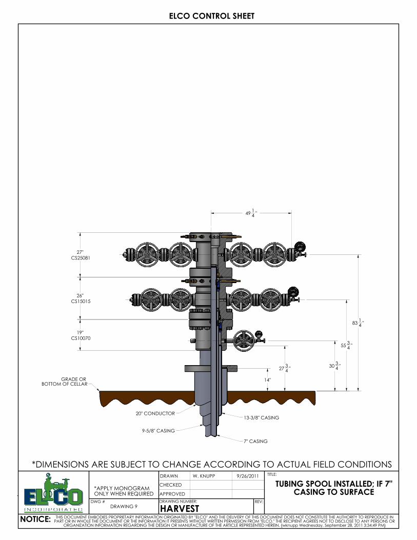
GRADE OR BOTTOM OF CELLAR
20" CONDUCTOR13-3/8" CASING
9-5/8" CASING
7" CASING
19"CS10070
26"
CS15015
27"
CS25081
3034 "
5534 "
8314 "
14"
4914 "
2734 "
*APPLY MONOGRAMONLY WHEN REQUIRED
DRAWING 9
ELCO CONTROL SHEET
9/26/2011
CHECKED
APPROVED
W. KNUPP
NOTICE:
TUBING SPOOL INSTALLED; IF 7" CASING TO SURFACE
TITLE:
THIS DOCUMENT EMBODIES PROPRIETARY INFORMATION ORIGINATED BY "ELCO" AND THE DELIVERY OF THIS DOCUMENT DOES NOT CONSTITUTE THE AUTHORITY TO REPRODUCE IN PART OR IN WHOLE THE DOCUMENT OR THE INFORMATION IT PRESENTS WITHOUT WRITTEN PERMISSION FROM "ELCO." THE RECIPIENT AGREES NOT TO DISCLOSE TO ANY PERSONS OR
ORGANIZATION INFORMATION REGARDING THE DESIGN OR MANUFACTURE OF THE ARTICLE REPRESENTED HEREIN. {wknupp Wednesday, September 28, 2011 3:34:49 PM}
DRAWING NUMBER:
HARVEST
DRAWN
DWG # REV:
*DIMENSIONS ARE SUBJECT TO CHANGE ACCORDING TO ACTUAL FIELD CONDITIONS
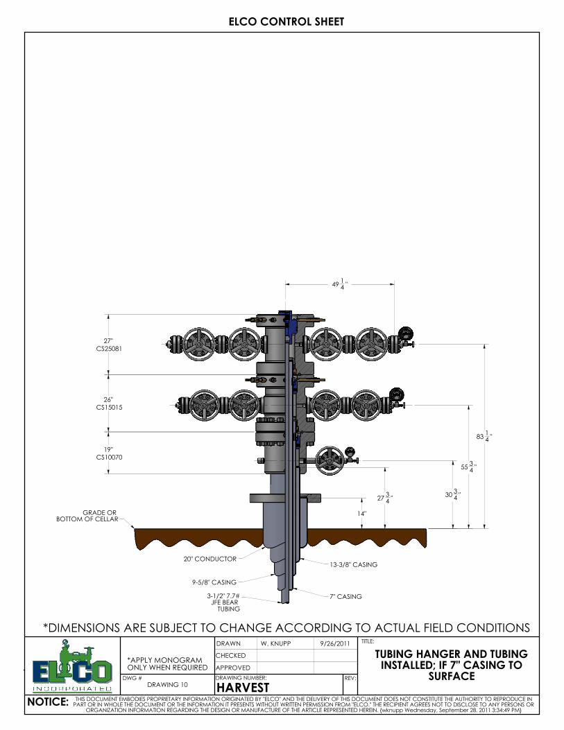
GRADE OR BOTTOM OF CELLAR
20" CONDUCTOR13-3/8" CASING
9-5/8" CASING
7" CASING3-1/2" 7.7#JFE BEAR TUBING
19"CS10070
26"
CS15015
27"
CS25081
3034 "
5534 "
8314 "
14"
4914 "
2734 "
*DIMENSIONS ARE SUBJECT TO CHANGE ACCORDING TO ACTUAL FIELD CONDITIONS
*APPLY MONOGRAMONLY WHEN REQUIRED
DRAWING 10
ELCO CONTROL SHEET
9/26/2011
CHECKED
APPROVED
W. KNUPP
NOTICE:
TUBING HANGER AND TUBING INSTALLED; IF 7" CASING TO
SURFACE
TITLE:
THIS DOCUMENT EMBODIES PROPRIETARY INFORMATION ORIGINATED BY "ELCO" AND THE DELIVERY OF THIS DOCUMENT DOES NOT CONSTITUTE THE AUTHORITY TO REPRODUCE IN PART OR IN WHOLE THE DOCUMENT OR THE INFORMATION IT PRESENTS WITHOUT WRITTEN PERMISSION FROM "ELCO." THE RECIPIENT AGREES NOT TO DISCLOSE TO ANY PERSONS OR
ORGANIZATION INFORMATION REGARDING THE DESIGN OR MANUFACTURE OF THE ARTICLE REPRESENTED HEREIN. {wknupp Wednesday, September 28, 2011 3:34:49 PM}
DRAWING NUMBER:
HARVEST
DRAWN
DWG # REV:
GRADE OR BOTTOM OF CELLAR
20" CONDUCTOR13-3/8" CASING
9-5/8" CASING
7" CASING3-1/2" 7.7#JFE BEAR TUBING
19"CS10070
26"
CS15015
27"
CS25081
102"
CS40110
3034 "
5534 "
8314 "
15712 "
14"
33"
5714 "
2734 "
*APPLY MONOGRAMONLY WHEN REQUIRED
DRAWING 11
ELCO CONTROL SHEET
9/26/2011
CHECKED
APPROVED
W. KNUPP
NOTICE:
PRODUCTION CONFIGURATION; IF 7" CASING TO SURFACE
TITLE:
THIS DOCUMENT EMBODIES PROPRIETARY INFORMATION ORIGINATED BY "ELCO" AND THE DELIVERY OF THIS DOCUMENT DOES NOT CONSTITUTE THE AUTHORITY TO REPRODUCE IN PART OR IN WHOLE THE DOCUMENT OR THE INFORMATION IT PRESENTS WITHOUT WRITTEN PERMISSION FROM "ELCO." THE RECIPIENT AGREES NOT TO DISCLOSE TO ANY PERSONS OR
ORGANIZATION INFORMATION REGARDING THE DESIGN OR MANUFACTURE OF THE ARTICLE REPRESENTED HEREIN. {wknupp Wednesday, September 28, 2011 3:34:49 PM}
DRAWING NUMBER:
HARVEST
DRAWN
DWG # REV:
*DIMENSIONS ARE SUBJECT TO CHANGE ACCORDING TO ACTUAL FIELD CONDITIONS
GRADE OR BOTTOM OF CELLAR
20" CONDUCTOR13-3/8" CASING
9-5/8" CASING
3-1/2" 7.7#JFE BEAR TUBING
19"CS10070
26"
CS15015
102"CS40110
3034 "
5534 "
13014 "
14"
33"
5714 "
2734 "
*DIMENSIONS ARE SUBJECT TO CHANGE ACCORDING TO ACTUAL FIELD CONDITIONS
*APPLY MONOGRAMONLY WHEN REQUIRED
DRAWING 12
ELCO CONTROL SHEET
9/26/2011
CHECKED
APPROVED
W. KNUPP
NOTICE:
ALTERNATE CONFIGURATION; NO 7" CASING TO SURFACE
TITLE:
THIS DOCUMENT EMBODIES PROPRIETARY INFORMATION ORIGINATED BY "ELCO" AND THE DELIVERY OF THIS DOCUMENT DOES NOT CONSTITUTE THE AUTHORITY TO REPRODUCE IN PART OR IN WHOLE THE DOCUMENT OR THE INFORMATION IT PRESENTS WITHOUT WRITTEN PERMISSION FROM "ELCO." THE RECIPIENT AGREES NOT TO DISCLOSE TO ANY PERSONS OR
ORGANIZATION INFORMATION REGARDING THE DESIGN OR MANUFACTURE OF THE ARTICLE REPRESENTED HEREIN. {wknupp Wednesday, September 28, 2011 3:34:49 PM}
DRAWING NUMBER:
HARVEST
DRAWN
DWG # REV:
55
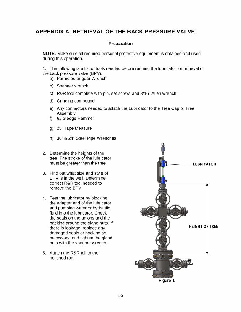
APPENDIX A: RETRIEVAL OF THE BACK PRESSURE VALVE
Preparation NOTE: Make sure all required personal protective equipment is obtained and used during this operation. 1. The following is a list of tools needed before running the lubricator for retrieval of
the back pressure valve (BPV): a) Parmelee or gear Wrench
b) Spanner wrench
c) R&R tool complete with pin, set screw, and 3/16” Allen wrench
d) Grinding compound
e) Any connectors needed to attach the Lubricator to the Tree Cap or Tree Assembly
f) 6# Sledge Hammer
g) 25’ Tape Measure h) 36” & 24” Steel Pipe Wrenches
2. Determine the heights of the tree. The stroke of the lubricator must be greater than the tree
3. Find out what size and style of
BPV is in the well. Determine correct R&R tool needed to remove the BPV
4. Test the lubricator by blocking
the adapter end of the lubricator and pumping water or hydraulic fluid into the lubricator. Check the seals on the unions and the packing around the gland nuts. If there is leakage, replace any damaged seals or packing as necessary, and tighten the gland nuts with the spanner wrench.
5. Attach the R&R toll to the
polished rod.
Figure 1
LUBRICATOR
HEIGHT OF TREE
56
6. Close the wing valve(s) to stop the flow in the tree. 7. Open the run of the tree and check the pressure at the top of the tree. 8. Measure the approximate distance from the tubing hanger to the top of the tree.
Also measure the distance between the gland nuts of the lubricator and subtract the width of the Parmelee or gear wrench. Divide the maximum incremental distance the polished rod can be moved into the distance between the tubing hanger and the top of the tree. This will determine the how many times polished rod will have to be moved in order to reach the tubing hanger.
9. Close the Swab valve, bleed off pressure and remove the tree cap nut for the
tree cap assembly. Removal Procedures
1. Suspend the lubricator over the tree and connect to the tree cap. 2. Open all needle valves on the lubricator to allow air to flow through the tool. 3. Coat the inside of the Parmelee or Gear wrench with grinding compound, and
attach the wrench to the polished rod so that it will turn to the left. 4. Repeatedly push the rod down into the tree, rotating the rod to the left until you
feel it stop. When this happens, you have reached the BPV. 5. Close needle valves C and D on the lubricator. 6. In order to align the threads of the R&R tool with the threads in the BPV, turn the
rod to the left slowly until a thread “hop” is felt. If a thread hop is not felt, try pushing the rod down further.
7. After the thread hop remove the Parmelee or Gear wrench and attach it so it will
turn to the right. 8. Make a mark on the polished rod using some grease, so that you can keep track
of how many rotations the R&R tool makes. 9. Rotate the rod to the right, keeping count of complete rotations that the rod
makes. After 6 or 7 rotations the R&R tool will push the piston in the BPV off its seat and allow pressure to fill the lubricator.
10. Immediately, check for leaks at the gland nuts, Autoclave fittings, and the tree
connection. If there is leakage rotate the R&R tool back out of the BPV, bleed off pressure and repair any leaks. If there are no leaks proceed with removal of the BPV.
11. Continue to rotate the rod to the right. NOTE: While watching the rod, make sure that the mark on the rod goes down until the pressure is equalized. If the mark goes up – STOP! Reset the BPV and work the ROD up and down, making sure the mark goes down, until the pressure is equalized.
57
12. When the R&R tool has screwed into the BPV, you will feel a significant decrease in torque after 2-3 rotations. This means the BPV has broken loose from the tubing hanger. Continue rotating, and the BPV will retract from the tubing hanger. If there is no decrease in torque, reset the BPV and equalize pressure before continuing.
13. Make sure the BPV is disengaged from the tubing hanger by pulling up on the
rod slightly. If the rod does not move, the BPV is still threaded into the hanger. Continue rotating the rod until it has completely disengaged.
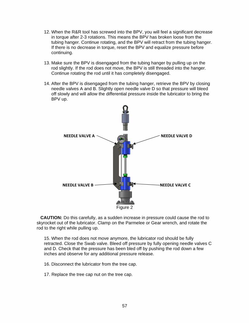
14. After the BPV is disengaged from the tubing hanger, retrieve the BPV by closing
needle valves A and B. Slightly open needle valve D so that pressure will bleed off slowly and will allow the differential pressure inside the lubricator to bring the BPV up.
Figure 2
CAUTION: Do this carefully, as a sudden increase in pressure could cause the rod to skyrocket out of the lubricator. Clamp on the Parmelee or Gear wrench, and rotate the rod to the right while pulling up. 15. When the rod does not move anymore, the lubricator rod should be fully
retracted. Close the Swab valve. Bleed off pressure by fully opening needle valves C and D. Check that the pressure has been bled off by pushing the rod down a few inches and observe for any additional pressure release.
16. Disconnect the lubricator from the tree cap. 17. Replace the tree cap nut on the tree cap.
NEEDLE VALVE D
NEEDLE VALVE C
NEEDLE VALVE A
NEEDLE VALVE B