Embed Size (px)
Citation preview
ELASTIC SYSTEMS FOR DYNAMIC RETROFITTING (ESDR) OF STRUCTURES Authors: Paolo Casadei, Ph.D., P.E. Consultant Engineer TEC.INN. S.r.l., Technical & Commercial Division Piazza Duomo 17 20121, Milano Italy Phone: (+39) 02- 8900108 Fax: (+39) 02- 45471830 Email: [email protected] Emo Agneloni, P.E. President TEC.INN. S.r.l., Head Quarters Via Y.Gagarin 73 06070, San Mariano - Perugia Italy Phone: (+39) 075- 5170096 Fax: (+39) 075- 5177546 Email: [email protected] About the Authors: Paolo Casadei is a consultant engineer in charge of R&D for TEC.INN. S.r.l. (www.tecinn.com). He received his PhD in Civil Engineering from the University of Missouri-Rolla, USA. He has been involved in numerous projects involving structural upgrade and rehabilitation of concrete and masonry structures using FRP advanced composite materials as well as full-scale in-situ load testing and structural monitoring. He is a member of ACI Committee 437, Strength Evaluation of Existing Concrete Structures, and ACI Committee 440 (FRP). He is also a member of AICO, Italian Fibers Composites Association for the Construction Industry. Emo Agneloni, entrepreneur, president of TEC.INN. S.r.l. (Innovative Technologies, www.tecinn.com) founded in 1986. He has more than 20 years experience in the repair and strengthening of concrete and masonry structures, specialized in using extremely innovative technologies and materials to restore, recover, strengthen and protect any type of structures, from infrastructures to historical-artistic-monumental buildings. He is a founding member of AICO, Italian Fibers Composites Association for the Construction Industry.
Abstract: Recent world events have showed that performance of buildings to blast loads is an ever increasing issue. Many older buildings contain un-reinforced masonry (URM) infill walls. Due to their low flexural capacity and their brittle mode of failure, these walls have a low resistance to out-of-plane loads, including a blast load. As a result, an effort has been undertaken to examine retrofit methods that are feasible to enhance their out-of-plane resistance. The use of externally bonded Fiber Reinforced Polymer (FRP) laminates has been proven, by several research studies around the world, to increase the out-of-plane load capacity and improve both in static and dynamic tests the performance of URM infill walls. One draw back of FRP is their lack of ductility at ultimate state. It is for this reason that new strengthening solutions are investigated in order to provide the necessary strength coupled with sufficient ductility. The present study has investigated the performance of a package that couples together the high strength of FRP systems with the ductility of a polyurea resin that can elongate up to 400%. The new strengthening system allows different layers of FRP and polyurea to: 1) provide the necessary strength to the infill wall subjected to out-of-plane forces, 2) provide a ballistic layer to catch flying debris, 3) guarantee sufficient deformations of the strengthened walls (as a car-airbag), dissipating energy without completely collapsing. Results from both static and field blast tests on 8 2x2 meter brick walls, will show the effect of different strengthening solutions to out-of-plane loads. Keywords: Ballistic protection, Blast-Seismic load, Blast-Seismic mitigation, Energy dissipation, FRP, Large Deformations, Polyurea, Strengthening. 1 INTRODUCTION
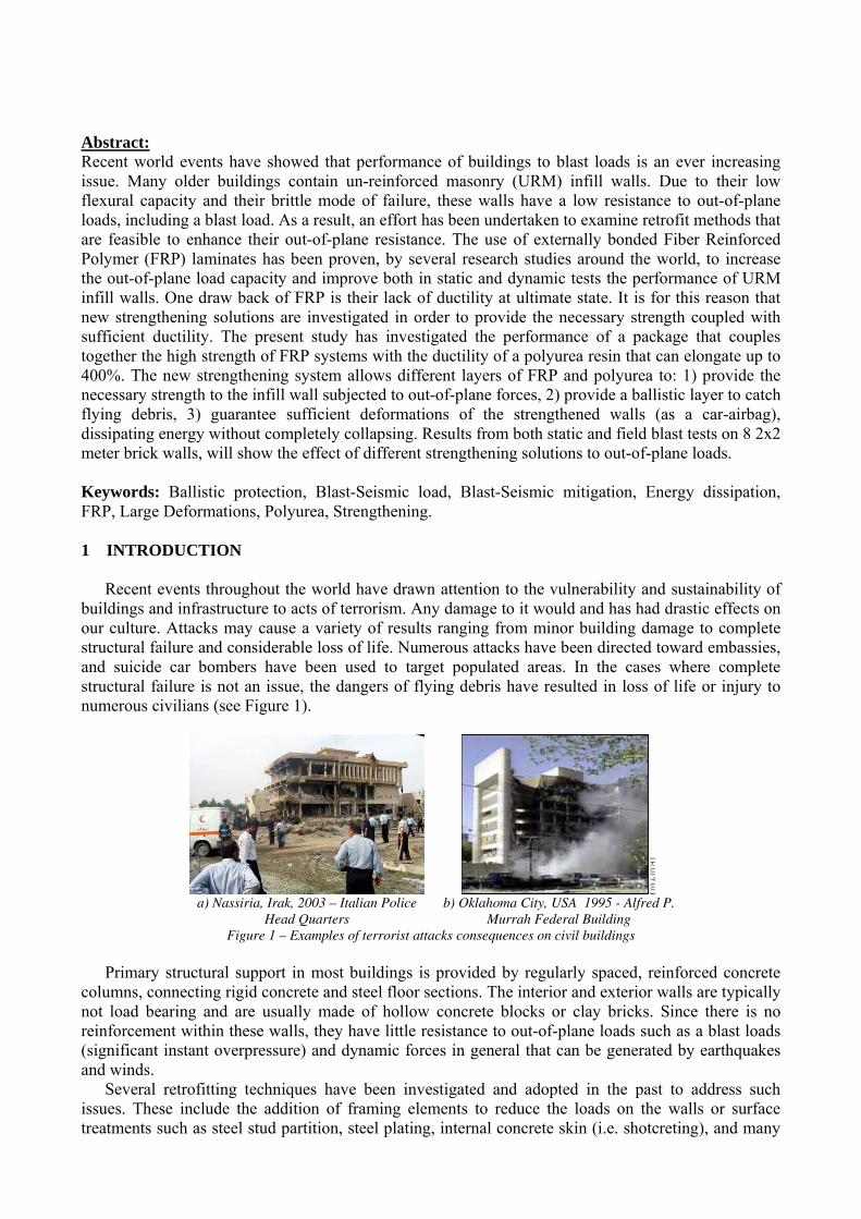
Recent events throughout the world have drawn attention to the vulnerability and sustainability of buildings and infrastructure to acts of terrorism. Any damage to it would and has had drastic effects on our culture. Attacks may cause a variety of results ranging from minor building damage to complete structural failure and considerable loss of life. Numerous attacks have been directed toward embassies, and suicide car bombers have been used to target populated areas. In the cases where complete structural failure is not an issue, the dangers of flying debris have resulted in loss of life or injury to numerous civilians (see Figure 1).
a) Nassiria, Irak, 2003 – Italian Police
Head Quarters b) Oklahoma City, USA 1995 - Alfred P.
Murrah Federal Building Figure 1 – Examples of terrorist attacks consequences on civil buildings
Primary structural support in most buildings is provided by regularly spaced, reinforced concrete
columns, connecting rigid concrete and steel floor sections. The interior and exterior walls are typically not load bearing and are usually made of hollow concrete blocks or clay bricks. Since there is no reinforcement within these walls, they have little resistance to out-of-plane loads such as a blast loads (significant instant overpressure) and dynamic forces in general that can be generated by earthquakes and winds.
Several retrofitting techniques have been investigated and adopted in the past to address such issues. These include the addition of framing elements to reduce the loads on the walls or surface treatments such as steel stud partition, steel plating, internal concrete skin (i.e. shotcreting), and many
others, to increase the strength and ductility of the walls[1]. Such retrofits often add significant mass to the structure and are time consuming, costly to carry out, and adversely affect the aesthetics of the upgraded area and in many cases the building as a whole. When such technique modifies the mass of the structure, it would increase the dynamic-induced inertia forces and may require strengthening of the footing as well leading to a more invasive and costly operation.
The above disadvantages and the need of more cost-efficient applications, have recently led engineers to the idea of using lightweight/high-strength, fiber-reinforced polymer FRP composites as strengthening materials, externally bonded to the surface of the material by manual lay-up. FRP materials have already massively entered the market of the retrofitting and strengthening industry, thanks to their high strength, durability, light weight and ease of installation characteristics as demonstrated worldwide by the recently published design guidelines in the US and in Europe (ACI[2], CNR[3], UK[4], FIB[5]). Their only draw back is their lack of ductility at ultimate state. It is for this reason that new strengthening solutions are investigated in order to provide the necessary strength, proper of FRP strengthening, coupled with sufficient ductility.
The present study has investigated the performance of a package that couples together the high strength of FRP systems with the ductility of polyurea resin that can elongate up to 400%. The new strengthening system allows different layers of FRP and polyurea to: 1) provide the necessary strength to the infill wall subjected to out-of-plane forces, 2) provide a ballistic layer to catch flying debris, 3) guarantee sufficient deformations of the strengthened walls, dissipating energy without completely collapsing. Results quasi-static tests on 10 2x2 meter brick (clay and concrete) walls, will show the effect of different strengthening solutions to out-of-plane loads. 2 BLAST LOADING
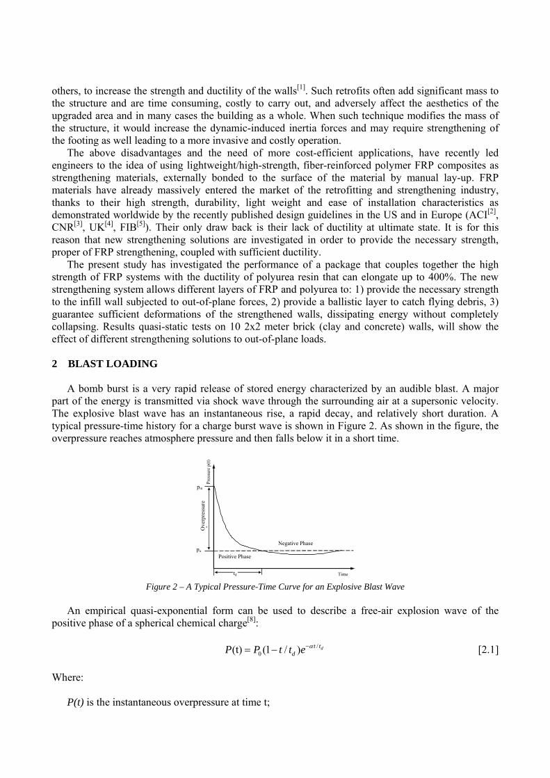
A bomb burst is a very rapid release of stored energy characterized by an audible blast. A major part of the energy is transmitted via shock wave through the surrounding air at a supersonic velocity. The explosive blast wave has an instantaneous rise, a rapid decay, and relatively short duration. A typical pressure-time history for a charge burst wave is shown in Figure 2. As shown in the figure, the overpressure reaches atmosphere pressure and then falls below it in a short time.
Pres
sure
p(t)
pa
pm
Ove
rpre
ssur
e 0
td
Positive Phase
Negative Phase
Time Figure 2 – A Typical Pressure-Time Curve for an Explosive Blast Wave
An empirical quasi-exponential form can be used to describe a free-air explosion wave of the
positive phase of a spherical chemical charge[8]:
/0(t) (1 / ) dt t
dP P t t e α−= − [2.1]
Where: P(t) is the instantaneous overpressure at time t;

P0 = (Pm – Pa) is the maximum or peak overpressure observed when t is zero, Pa is atmosphere pressure; Pm is the peak pressure when t is zero; e is the base of natural logarithms; α is the decay factor; td is the positive pressure duration. Since the positive phase of an explosion causes most of the damage for heavy structures[8], the blast
load parameters are defined in this project in reference to the positive phase. In particular the parameter that is mostly significative is the initial peak of overpressure P0 defined
by Kinney and Graham[8]:
222
2
0
35.11
32.01
048.01
5.41808
⎟⎠⎞
⎜⎝⎛+⎟
⎠⎞
⎜⎝⎛+⎟
⎠⎞
⎜⎝⎛+
⎥⎥⎦
⎤
⎢⎢⎣
⎡⎟⎠⎞
⎜⎝⎛+
=ZZZ
ZPP
a
[2.2] Where: Pa is the atmospheric pressure, taken as 0.101 MPa; Z is the scaled distance.
31−
×= WdZ [2.3] Where: W is the charge weight in kilograms (equivalent mass of TNT); d is the standoff distance in meters. In Figure 3 is reported a typical “terrorist site scene” with the center of burst, consisting in a truck,
positioned at the stand-off distance from the building to attack.
Figure 3 – A typical site scene in a terrorist attack situation
Combining equations [2.3] with [2.2] it is possible to determine the initial peak of overpressure
that insists on the building that we are analyzing. The equations reported are valid only when we are dealing with what is called “air blast”, that means that the center of a spherical charge is at least 2-3 times its diameter away from the target surface (see Figure 4).

Spherical charge
r
2r Target surface
Figure 4 – Air Blast vs Contact Charges
In all these equations, the charge is supposed to be spherical. Because equation [2.3] relates the
stand-off distance with the charge weight, indirectly also relates the diameter of the spherical charge (that can be easily computed knowing the density of the material used and its weight) with the stand-off distance. It is for these reasons that for values of Z less than 1-1.5 we cannot consider anymore the blast as an “air blast” bur rather a “contact charge” that needs to be dealt in a different way. It must be said though that for the type of problems we are dealing with, in most cases we are facing an “air-blast” situation as described in Figure 3.
In Figure 5 is reported a plot of how the instant peak overpressure varies as a function of the stand-off distance and the weight of explosive blown. To make it easier reading the plot, it is also reported a drawing of what type of vehicle could carry a certain amount of explosive. These information, provided by the U.S. AIR Force “Installation Force Protection Guide”, are reported in US customary units (1 ft=0,30 m; 1 lbs= 0,45 kg; 1 psi=0,069 bar).
Figure 5 – Incident Overpressure as a function of stand-off distance and explosive net weight
Available international guidelines provide values of incident overpressures considered to be lethal
or very destructive. Table 1 reports the value indicated by the Italian law regarding risk analysis of inflammable and toxic liquid deposits.
Table 1 - Reference values to evaluate blast effects (*)
DAMAGE LEVELS TO STRUCTURES AND PEOPLE (bar) Blast Scenario High
Lethality Start of lethality
Irreversible Damage
Reversible damage
Damage to the Structure/Domino Effect
Peak Overpressure 0,6 (0.3) 0,14 0,07 0,03 0,3 (*)“Decreto Ministeriale 20 Ottobre 1998”, “Criteria of analysis and evaluation of safety provisions for deposits of liquids easily inflammable and/or toxic”, in Italian.
Table 2 reports instead an American guide line, similar to the previous one but dealing mainly with
the processes industries in general.

Table 2 - Reference values to evaluate blast effects (*)
DAMAGE LEVELS TO STRUCTURES AND PEOPLE (bar)
Blast Scenario
Observance of the stand-off distance (95%
of chance that no serious damage occurs)
Inhabitable houses (partial
demolition)
Inhabitable houses
(partial roof demolition)
Inhabitable houses (50% demolition of masonry structures)
Inhabitable houses (almost complete
demolition of houses)
Peak Overpressure 0,6 (0.3) 0,14 0,07 0,03 0,3 (*)LEES, “Loss Prevention in the process industries”, Lees F.P. 1980.
In both reported tables, the values of peak overpressure (in bar) are clearly very low if compared
with the overpressure that could be generated by van loaded with TNT and placed anywhere away from the targeted building. Figure 5 clearly shows that a van loaded with roughly 500kg (1000 lbs) and placed at 300 mt (500 ft) away from the target, can easily generate an overpressure of 0.07 bars (1 psi) that according to both guidelines reported, causes irreversible damages and inhabitable houses.
Because many existing critical buildings in our cities, such as embassies, police stations, hospitals, military facilities do not have the possibility of guaranteeing large stand-off distances, the values of overpressure that could be easily generated by van loaded with explosives, are extremely dangerous and need to be addressed.
Retrofitting and strengthening to provide blast mitigation becomes consequently a high priority for owners of public and private critical structures, that can be potentially subjected to terrorist attacks.
3 INNOVATIVE BLAST RETROFITTING SYSTEM BASED ON POLYUREA RESIN
Blast retrofitting with FRP composite materials is a recent innovative solution of the construction industry[6][7]. FRPs guarantee increase in strength thanks to their linear elastic up to failure ultimate strength (i.e. up to ten times the one of conventional structural steel) and energy absorption thanks to improved ultimate deformations with respect to un-reinforced masonry (URM). There are though several drawbacks in such type of application that have induced researchers to investigate alternative and even more efficient solutions. Firstly FRP, as commonly used in this type of applications, need a hand-lay-up application, which means that fibers need to be impregnated by hand in the field using mostly epoxy resins (using a roll just like for wall-paper application) that at the same time impregnate and bond the composite on the substrate (previously sand blasted to secure a better bond); in such type of application generally FRP create a grid that does not cover the entire wall surface, with consequent difficulty to catch all flying debris (see Figure 6 and Figure 7).
a) Masonry brick wall strengthened with
AFRP sheets installed with manual lay-up b) Detail view of the strengthening
over the bricks Figure 6 – Strengthening masonry walls with FRP sheets installed by manual lay-up
Secondly when the FRP system reaches its ultimate strength the rupture is sudden leading to a
complete collapse of the member since the structure has no residual capacity, fiber and resin are linear elastic up to failure, with high elastic modulus that does not allow for further deformations.
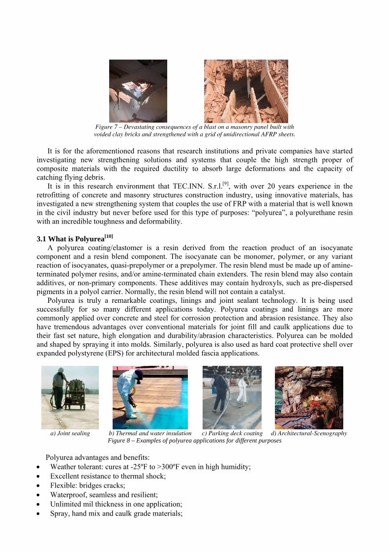
Figure 7 – Devastating consequences of a blast on a masonry panel built with voided clay bricks and strengthened with a grid of unidirectional AFRP sheets.
It is for the aforementioned reasons that research institutions and private companies have started
investigating new strengthening solutions and systems that couple the high strength proper of composite materials with the required ductility to absorb large deformations and the capacity of catching flying debris.
It is in this research environment that TEC.INN. S.r.l.[9], with over 20 years experience in the retrofitting of concrete and masonry structures construction industry, using innovative materials, has investigated a new strengthening system that couples the use of FRP with a material that is well known in the civil industry but never before used for this type of purposes: “polyurea”, a polyurethane resin with an incredible toughness and deformability.
3.1 What is Polyurea[10]
A polyurea coating/elastomer is a resin derived from the reaction product of an isocyanate component and a resin blend component. The isocyanate can be monomer, polymer, or any variant reaction of isocyanates, quasi-prepolymer or a prepolymer. The resin blend must be made up of amine-terminated polymer resins, and/or amine-terminated chain extenders. The resin blend may also contain additives, or non-primary components. These additives may contain hydroxyls, such as pre-dispersed pigments in a polyol carrier. Normally, the resin blend will not contain a catalyst.
Polyurea is truly a remarkable coatings, linings and joint sealant technology. It is being used successfully for so many different applications today. Polyurea coatings and linings are more commonly applied over concrete and steel for corrosion protection and abrasion resistance. They also have tremendous advantages over conventional materials for joint fill and caulk applications due to their fast set nature, high elongation and durability/abrasion characteristics. Polyurea can be molded and shaped by spraying it into molds. Similarly, polyurea is also used as hard coat protective shell over expanded polystyrene (EPS) for architectural molded fascia applications.
a) Joint sealing b) Thermal and water insulation c) Parking deck coating d) Architectural-Scenography
Figure 8 – Examples of polyurea applications for different purposes Polyurea advantages and benefits:
• Weather tolerant: cures at -25ºF to >300ºF even in high humidity; • Excellent resistance to thermal shock; • Flexible: bridges cracks; • Waterproof, seamless and resilient; • Unlimited mil thickness in one application; • Spray, hand mix and caulk grade materials;

• Excellent bond strengths to properly prepared substrates; • Resistant to various solvents, caustics and mild acids; • Low permeability, excellent sustainability; • No VOC’s and little to no odor; • Some systems are potable approved;
TEC.INN. S.r.l. has characterized[11] the mechanical properties of polyurea used and installed for retrofit purposes in the testing campaign later on presented and discussed.
a) Dog-bone polyurea specimens
ready for testing b) Sample ready to be
tested in tension c) Incredible elongation of the specimen during testing
Figure 9 – Mechanical characterization of polyurea In Table 3 are reported the experimental results obtained from the aforementioned testing
campaign.
Table 3 - Mechanical properties of polyurea
Material Ultimate Tensile
Strength, ffu [MPa]
Ultimate Rupture Strain εfu
[%]
Tensile Modulus of Elasticity E,
[MPa] Polyurea(*) 15 ≥375 ≤4,3
(*) Values provided by SGM S.r.l.[12], a certified testing laboratory and reported by La Rana[11]. 3.2 Elastic Systems for Dynamic Retrofitting: E.S.D.R.® [13]
By combining FRP and polyurea, TEC.INN. S.r.l. has patented[13] a retrofitting system that is called: Elastic Systems for Dynamic Retrofitting. The E.S.D.R.® system is a modular strengthening package, consisting of 3 layers realized with different stacking of materials, that can be tailored for any scenario depending on the level of blast mitigation that needs to be achieved for the building, with the possibility that not all of the three layers needs to be applied in all cases and for any type of structure and blast scenario.
The new innovative strengthening systems consists of the following layers (see also Figure 10): • 1st “Strengthening” layer –1-2 mm thick – realized with the FRP technology, to improve
the flexural (out of plane) strength of the infill masonry walls; • 2nd “Dissipative” layer – variable thickness – consists in overlapping multiple layers
formed by different fiber grids impregnated by polyurea, with one or more ballistic layers in between. The choice of the number of layers (polyurea-grid-polyurea) and of the number of ballistic layers depends upon the design constrains fixed by the needed level of protection;
• 3rd “Elastic” layer – 10 mm average thickness – formed by a thick external layer of polyurea, properly anchored to the main bearing frame by means of advanced composite bars, in order to improve the ductility of the infill masonry wall and to guarantee a sort of “catching net” for any type of debris that may have passed through the other layers. Such layer may slide over the previous ones, thanks to a chemical debonding layer properly installed, possibly reaching its deformation performances (up to 400%) and consequently non only enhancing the dissipative performances of the system but also performing similarly to a car air-bag.
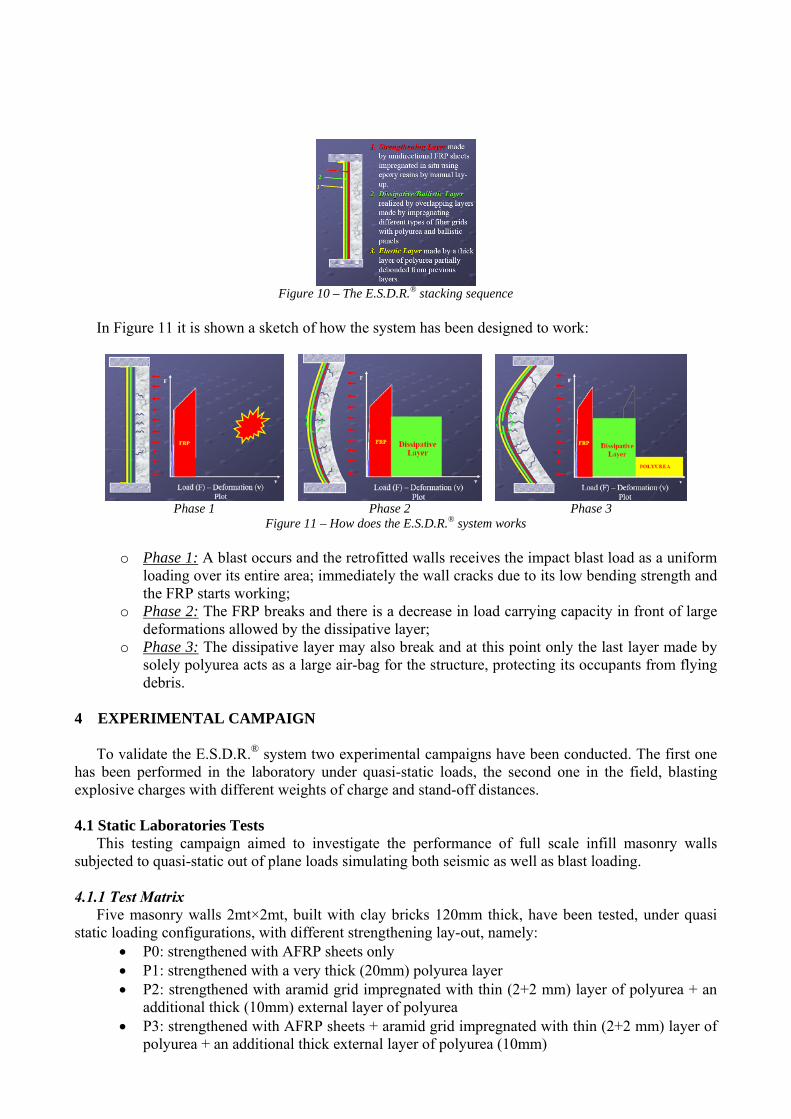
Figure 10 – The E.S.D.R.® stacking sequence
In Figure 11 it is shown a sketch of how the system has been designed to work:
Phase 1 Phase 2 Phase 3
Figure 11 – How does the E.S.D.R.® system works
o Phase 1: A blast occurs and the retrofitted walls receives the impact blast load as a uniform loading over its entire area; immediately the wall cracks due to its low bending strength and the FRP starts working;
o Phase 2: The FRP breaks and there is a decrease in load carrying capacity in front of large deformations allowed by the dissipative layer;
o Phase 3: The dissipative layer may also break and at this point only the last layer made by solely polyurea acts as a large air-bag for the structure, protecting its occupants from flying debris.
4 EXPERIMENTAL CAMPAIGN
To validate the E.S.D.R.® system two experimental campaigns have been conducted. The first one
has been performed in the laboratory under quasi-static loads, the second one in the field, blasting explosive charges with different weights of charge and stand-off distances.
4.1 Static Laboratories Tests
This testing campaign aimed to investigate the performance of full scale infill masonry walls subjected to quasi-static out of plane loads simulating both seismic as well as blast loading.
4.1.1 Test Matrix
Five masonry walls 2mt×2mt, built with clay bricks 120mm thick, have been tested, under quasi static loading configurations, with different strengthening lay-out, namely:
• P0: strengthened with AFRP sheets only • P1: strengthened with a very thick (20mm) polyurea layer • P2: strengthened with aramid grid impregnated with thin (2+2 mm) layer of polyurea + an
additional thick (10mm) external layer of polyurea • P3: strengthened with AFRP sheets + aramid grid impregnated with thin (2+2 mm) layer of
polyurea + an additional thick external layer of polyurea (10mm)
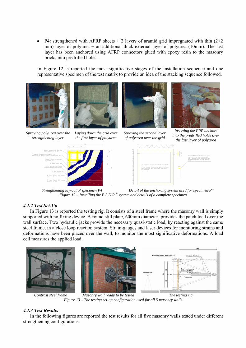
• P4: strengthened with AFRP sheets + 2 layers of aramid grid impregnated with thin (2+2 mm) layer of polyurea + an additional thick external layer of polyurea (10mm). The last layer has been anchored using AFRP connectors glued with epoxy resin to the masonry bricks into predrilled holes.
In Figure 12 is reported the most significative stages of the installation sequence and one representative specimen of the test matrix to provide an idea of the stacking sequence followed.
Spraying polyurea over the
strengthening layer Laying down the grid over the first layer of polyurea
Spraying the second layer of polyurea over the grid
Inserting the FRP anchors into the predrilled holes over
the last layer of polyurea
Strengthening lay-out of specimen P4 Detail of the anchoring system used for specimen P4
Figure 12 – Installing the E.S.D.R.® system and details of a complete specimen
4.1.2 Test Set-Up In Figure 13 is reported the testing rig. It consists of a steel frame where the masonry wall is simply
supported with no fixing device. A round still plate, 600mm diameter, provides the patch load over the wall surface. Two hydraulic jacks provide the necessary quasi-static load, by reacting against the same steel frame, in a close loop reaction system. Strain-gauges and laser devices for monitoring strains and deformations have been placed over the wall, to monitor the most significative deformations. A load cell measures the applied load.
Contrast steel frame Masonry wall ready to be tested The testing rig
Figure 13 – The testing set-up configuration used for all 5 masonry walls
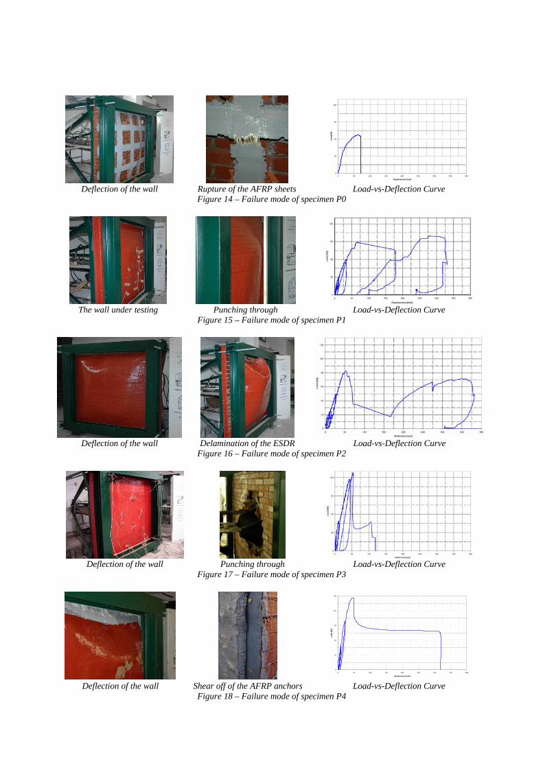
4.1.3 Test Results In the following figures are reported the test results for all five masonry walls tested under different
strengthening configurations.
0
30
60
90
120
0 50 100 150 200 250 300 350 400
Displacement [mm]
Load
[kN
]
Deflection of the wall Rupture of the AFRP sheets Load-vs-Deflection Curve
Figure 14 – Failure mode of specimen P0
The wall under testing Punching through Load-vs-Deflection Curve
Figure 15 – Failure mode of specimen P1
Deflection of the wall Delamination of the ESDR Load-vs-Deflection Curve
Figure 16 – Failure mode of specimen P2
Deflection of the wall Punching through Load-vs-Deflection Curve
Figure 17 – Failure mode of specimen P3
0
30
60
90
120
150
0 50 100 150 200 250 300 350 400
Displacement [mm]
Load
[kN
]
Deflection of the wall Shear off of the AFRP anchors Load-vs-Deflection Curve
Figure 18 – Failure mode of specimen P4
4.2 Blast Tests This testing campaign aimed to investigate the performance of full scale masonry walls (three made
with half solid concrete bocks and two with clay bricks) subjected to real blast loads.
4.2.1 Test Matrix Five masonry walls 2mt×2mt of two different types of bricks (clay and concrete) have been tested
under different strengthening configurations and under different blast loads, by varying the weight of charge and stand-off distance, namely:
• PS0: (wall of clay bricks) strengthened with ARFP sheets + 4 layers of aramid grid impregnated with thin (2+2 mm) layer of polyurea + an additional thick external layer of polyurea (10mm). The last layer has been anchored using AFRP connectors glued to the masonry bricks into predrilled holes;
• PS1: (wall of hollow clay blocks) strengthened with ARFP sheets + 2 layers of aramid grid impregnated with thin (2+2 mm) layer of polyurea + an additional thick external layer of polyurea (15mm). The last layer has been anchored using AFRP connectors glued to the masonry bricks into predrilled holes;
• PS2: identical to PS1; • PS3: (wall of hollow clay blocks) strengthened with AFRP sheets only; • PS4: (wall of clay bricks) strengthened with ARFP sheets + 3 layers of aramid grid
impregnated with thin (2+2 mm) layer of polyurea + an additional thick external layer of polyurea (10mm). The last layer has been anchored using AFRP connectors glued to the masonry bricks into predrilled holes.
The explosive used in all tests was “Eurogelatina 1”: it is a blasting cap sensitive gelatinous explosive that does not contain any nitroaromatic compound (TNT).
• Density 1.45 g/cm2 • Energy of detonation 4.70 MJ/kg
The explosive was modeled to be as much spherical as possible and positioned at a predetermined distance (R) from the center of the charge to the masonry panel.
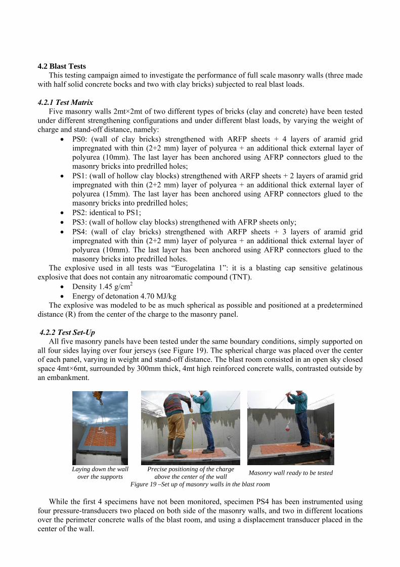
4.2.2 Test Set-Up
All five masonry panels have been tested under the same boundary conditions, simply supported on all four sides laying over four jerseys (see Figure 19). The spherical charge was placed over the center of each panel, varying in weight and stand-off distance. The blast room consisted in an open sky closed space 4mt×6mt, surrounded by 300mm thick, 4mt high reinforced concrete walls, contrasted outside by an embankment.
Laying down the wall
over the supports Precise positioning of the charge
above the center of the wall Masonry wall ready to be tested
Figure 19 –Set up of masonry walls in the blast room While the first 4 specimens have not been monitored, specimen PS4 has been instrumented using
four pressure-transducers two placed on both side of the masonry walls, and two in different locations over the perimeter concrete walls of the blast room, and using a displacement transducer placed in the center of the wall.
In addition for specimen PS4 two different blast series tests have been done as indicated in Figure 20. This two series allowed to exactly determining the pressure in all the positions over the wall and calibrating the model for charges very close to the target surface, where the air blast model is not predicting very well the overpressure.
Blasts Blasts Sr.1Sr.1
Blasts Blasts Sr.2Sr.2
Pressure Pressure TransducersTransducers
10 cm10 cm
25 cm25 cm
25 cm25 cm
50 cm50 cm50 cm50 cm
25 cm25 cm
25 cm25 cm
80 cm80 cm
20 cm20 cmDisplacement TransducerDisplacement Transducer
Blasts Blasts Sr.1Sr.1
Blasts Blasts Sr.2Sr.2
Pressure Pressure TransducersTransducers
10 cm10 cm
25 cm25 cm
25 cm25 cm
50 cm50 cm50 cm50 cm
25 cm25 cm
25 cm25 cm
80 cm80 cm
20 cm20 cm
Blasts Blasts Sr.1Sr.1
Blasts Blasts Sr.2Sr.2
Pressure Pressure TransducersTransducers
10 cm10 cm
25 cm25 cm
25 cm25 cm
50 cm50 cm50 cm50 cm
25 cm25 cm
25 cm25 cm
80 cm80 cm
20 cm20 cmDisplacement TransducerDisplacement Transducer
Figure 20 – Blast test series on specimen PS4
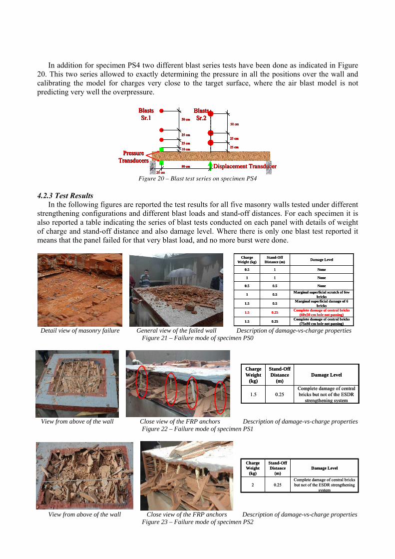
4.2.3 Test Results In the following figures are reported the test results for all five masonry walls tested under different
strengthening configurations and different blast loads and stand-off distances. For each specimen it is also reported a table indicating the series of blast tests conducted on each panel with details of weight of charge and stand-off distance and also damage level. Where there is only one blast test reported it means that the panel failed for that very blast load, and no more burst were done.
Complete damage of central bricks
(75x80 cm hole not passing)0.251.5
Complete damage of central bricks (60x50 cm hole not passing)0.251.5
Marginal superficial damage of 6 bricks0.51.5
Marginal superficial scratch of few bricks0.51
None0.50.5
None11
None10.5
Damage LevelStand-Off Distance (m)
Charge Weight (kg)
Complete damage of central bricks (75x80 cm hole not passing)0.251.5
Complete damage of central bricks (60x50 cm hole not passing)0.251.5
Marginal superficial damage of 6 bricks0.51.5
Marginal superficial scratch of few bricks0.51
None0.50.5
None11
None10.5
Damage LevelStand-Off Distance (m)
Charge Weight (kg)
Detail view of masonry failure General view of the failed wall Description of damage-vs-charge properties
Figure 21 – Failure mode of specimen PS0
Complete damage of central bricks but not of the ESDR
strengthening system0.251.5
Damage LevelStand-Off Distance
(m)
Charge Weight
(kg)Complete damage of central bricks but not of the ESDR
strengthening system0.251.5
Damage LevelStand-Off Distance
(m)
Charge Weight
(kg)
View from above of the wall Close view of the FRP anchors Description of damage-vs-charge properties Figure 22 – Failure mode of specimen PS1
Complete damage of central bricks but not of the ESDR strengthening
system0.252
Damage LevelStand-Off Distance
(m)
Charge Weight
(kg)Complete damage of central bricks but not of the ESDR strengthening
system0.252
Damage LevelStand-Off Distance
(m)
Charge Weight
(kg)
View from above of the wall Close view of the FRP anchors Description of damage-vs-charge properties Figure 23 – Failure mode of specimen PS2
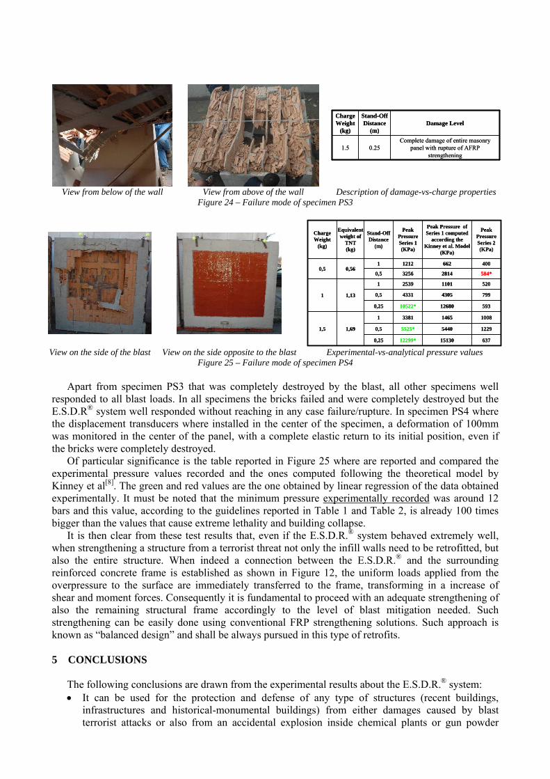
Complete damage of entire masonry panel with rupture of AFRP
strengthening0.251.5
Damage LevelStand-Off Distance
(m)
Charge Weight
(kg)Complete damage of entire masonry
panel with rupture of AFRP strengthening
0.251.5
Damage LevelStand-Off Distance
(m)
Charge Weight
(kg)
View from below of the wall View from above of the wall Description of damage-vs-charge properties Figure 24 – Failure mode of specimen PS3
15130
5440
1465
12680
4305
1101
2814
662
Peak Pressure of Series 1 computed
according the Kinney et al. Model
(KPa)
12295525*0,5
100833811
1,69
59310522*0,25
79943310,5
400121210,560,5
584*32560,5
52025391
1,131
637
Peak Pressure Series 2 (KPa)
12299*
Peak Pressure Series 1 (KPa)
Equivalent weight of
TNT (kg)
0,25
1,5
Stand-Off Distance
(m)
Charge Weight
(kg)
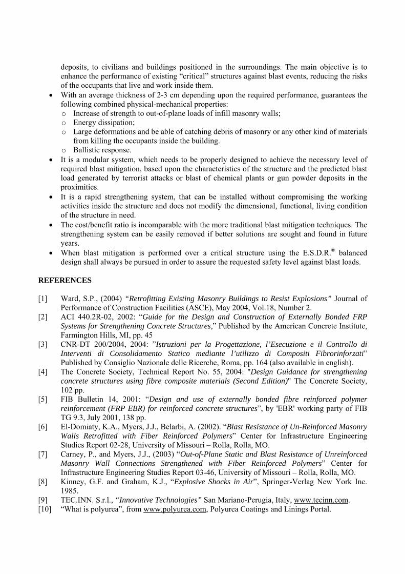
View on the side of the blast View on the side opposite to the blast Experimental-vs-analytical pressure values Figure 25 – Failure mode of specimen PS4
Apart from specimen PS3 that was completely destroyed by the blast, all other specimens well
responded to all blast loads. In all specimens the bricks failed and were completely destroyed but the E.S.D.R® system well responded without reaching in any case failure/rupture. In specimen PS4 where the displacement transducers where installed in the center of the specimen, a deformation of 100mm was monitored in the center of the panel, with a complete elastic return to its initial position, even if the bricks were completely destroyed.
Of particular significance is the table reported in Figure 25 where are reported and compared the experimental pressure values recorded and the ones computed following the theoretical model by Kinney et al[8]. The green and red values are the one obtained by linear regression of the data obtained experimentally. It must be noted that the minimum pressure experimentally recorded was around 12 bars and this value, according to the guidelines reported in Table 1 and Table 2, is already 100 times bigger than the values that cause extreme lethality and building collapse.
It is then clear from these test results that, even if the E.S.D.R.® system behaved extremely well, when strengthening a structure from a terrorist threat not only the infill walls need to be retrofitted, but also the entire structure. When indeed a connection between the E.S.D.R.® and the surrounding reinforced concrete frame is established as shown in Figure 12, the uniform loads applied from the overpressure to the surface are immediately transferred to the frame, transforming in a increase of shear and moment forces. Consequently it is fundamental to proceed with an adequate strengthening of also the remaining structural frame accordingly to the level of blast mitigation needed. Such strengthening can be easily done using conventional FRP strengthening solutions. Such approach is known as “balanced design” and shall be always pursued in this type of retrofits. 5 CONCLUSIONS
The following conclusions are drawn from the experimental results about the E.S.D.R.® system: • It can be used for the protection and defense of any type of structures (recent buildings,
infrastructures and historical-monumental buildings) from either damages caused by blast terrorist attacks or also from an accidental explosion inside chemical plants or gun powder
deposits, to civilians and buildings positioned in the surroundings. The main objective is to enhance the performance of existing “critical” structures against blast events, reducing the risks of the occupants that live and work inside them.
• With an average thickness of 2-3 cm depending upon the required performance, guarantees the following combined physical-mechanical properties: o Increase of strength to out-of-plane loads of infill masonry walls; o Energy dissipation; o Large deformations and be able of catching debris of masonry or any other kind of materials
from killing the occupants inside the building. o Ballistic response.
• It is a modular system, which needs to be properly designed to achieve the necessary level of required blast mitigation, based upon the characteristics of the structure and the predicted blast load generated by terrorist attacks or blast of chemical plants or gun powder deposits in the proximities.
• It is a rapid strengthening system, that can be installed without compromising the working activities inside the structure and does not modify the dimensional, functional, living condition of the structure in need.
• The cost/benefit ratio is incomparable with the more traditional blast mitigation techniques. The strengthening system can be easily removed if better solutions are sought and found in future years.
• When blast mitigation is performed over a critical structure using the E.S.D.R.® balanced design shall always be pursued in order to assure the requested safety level against blast loads.
REFERENCES [1] Ward, S.P., (2004) “Retrofitting Existing Masonry Buildings to Resist Explosions” Journal of
Performance of Construction Facilities (ASCE), May 2004, Vol.18, Number 2. [2] ACI 440.2R-02, 2002: “Guide for the Design and Construction of Externally Bonded FRP
Systems for Strengthening Concrete Structures,” Published by the American Concrete Institute, Farmington Hills, MI, pp. 45
[3] CNR-DT 200/2004, 2004: ”Istruzioni per la Progettazione, l’Esecuzione e il Controllo di Interventi di Consolidamento Statico mediante l’utilizzo di Compositi Fibrorinforzati” Published by Consiglio Nazionale delle Ricerche, Roma, pp. 164 (also available in english).
[4] The Concrete Society, Technical Report No. 55, 2004: "Design Guidance for strengthening concrete structures using fibre composite materials (Second Edition)" The Concrete Society, 102 pp.
[5] FIB Bulletin 14, 2001: “Design and use of externally bonded fibre reinforced polymer reinforcement (FRP EBR) for reinforced concrete structures”, by 'EBR' working party of FIB TG 9.3, July 2001, 138 pp.
[6] El-Domiaty, K.A., Myers, J.J., Belarbi, A. (2002). “Blast Resistance of Un-Reinforced Masonry Walls Retrofitted with Fiber Reinforced Polymers” Center for Infrastructure Engineering Studies Report 02-28, University of Missouri – Rolla, Rolla, MO.
[7] Carney, P., and Myers, J.J., (2003) “Out-of-Plane Static and Blast Resistance of Unreinforced Masonry Wall Connections Strengthened with Fiber Reinforced Polymers” Center for Infrastructure Engineering Studies Report 03-46, University of Missouri – Rolla, Rolla, MO.
[8] Kinney, G.F. and Graham, K.J., “Explosive Shocks in Air”, Springer-Verlag New York Inc. 1985.
[9] TEC.INN. S.r.l., “Innovative Technologies” San Mariano-Perugia, Italy, www.tecinn.com. [10] “What is polyurea”, from www.polyurea.com, Polyurea Coatings and Linings Portal.

[11] La Rana, A., (2005) “Indagine sperimentale preliminare sulle potenzialità della polyurea per la messa in sicurezza delle tamponature” Undergraduate Dissertation, University of Naples -Federico II, Naples, Italy, pp.172, in Italian.
[12] SGM S.r.l., Certified Laboratories, San Mariano-Perugia, Italy, www.sgmlaboratorio.com. [13] “Elastic Systems for Dynamic Retrofitting (E.S.D.R.®)”, patented RM/2005/A000066.