Embed Size (px)
Citation preview

Bull Earthquake Eng (2010) 8:955–972DOI 10.1007/s10518-010-9176-8
ORIGINAL RESEARCH PAPER
Elastic period of sub-standard reinforced concretemoment resisting frame buildings
Gerardo M. Verderame · Iunio Iervolino ·Gaetano Manfredi
Received: 1 May 2009 / Accepted: 21 February 2010 / Published online: 10 March 2010© Springer Science+Business Media B.V. 2010
Abstract The fundamental period has a primary role in seismic design and assessment asit is the main feature of the structure that allows one to determine the elastic demand and,indirectly, the required inelastic performance in static procedures. In fact, the definition ofeasy to manage relationships for the assessment of the elastic period has been the subject ofa significant deal of both experimental and numerical/analytical studies, some of which havebeen acknowledged by codes and guidelines worldwide. Moreover, this kind of informationis useful for territorial-scale seismic loss assessment methodologies. In the majority of cases,the assessment of the period is considered as function of the structural system classificationand number of storeys or height. Reinforced concrete structures, comprising most of thebuilding stock in Italy and in seismic prone areas in Europe and in the Mediterranean region,were built after the Second World War and are designed with obsolete seismic codes, if not forgravity loads only. Therefore, a class of buildings featuring the same height and/or numberof storeys may show a significant variability of the structural system. This, along with thecontribution of the stair module, may affect the elastic periods in the two main directionsof a three-dimensional building. In the study presented these issues are investigated withreference to a population of existing RC structures designed acknowledging the practice atthe time of supposed construction (e.g., simulated design) and with reference to the relativeenforced code. The elastic period is evaluated for both main directions of the buildings ofthe considered sample, and regression analysis is employed to capture the dependency of theelastic dynamic properties of the structures as a function of mass and stiffness.
Keywords Elastic period · Sub-standard · Reinforced concrete · Buildings · Stairs
G. M. Verderame (B) · I. Iervolino · G. ManfrediDipartimento di Ingegneria Strutturale, Università degli Studi di Napoli Federico II, Via Claudio 21,80125 Naples, Italye-mail: [email protected]
123
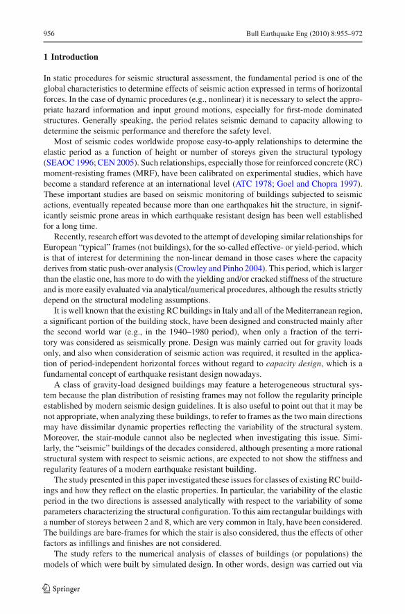
956 Bull Earthquake Eng (2010) 8:955–972
1 Introduction
In static procedures for seismic structural assessment, the fundamental period is one of theglobal characteristics to determine effects of seismic action expressed in terms of horizontalforces. In the case of dynamic procedures (e.g., nonlinear) it is necessary to select the appro-priate hazard information and input ground motions, especially for first-mode dominatedstructures. Generally speaking, the period relates seismic demand to capacity allowing todetermine the seismic performance and therefore the safety level.
Most of seismic codes worldwide propose easy-to-apply relationships to determine theelastic period as a function of height or number of storeys given the structural typology(SEAOC 1996; CEN 2005). Such relationships, especially those for reinforced concrete (RC)moment-resisting frames (MRF), have been calibrated on experimental studies, which havebecome a standard reference at an international level (ATC 1978; Goel and Chopra 1997).These important studies are based on seismic monitoring of buildings subjected to seismicactions, eventually repeated because more than one earthquakes hit the structure, in signif-icantly seismic prone areas in which earthquake resistant design has been well establishedfor a long time.
Recently, research effort was devoted to the attempt of developing similar relationships forEuropean “typical” frames (not buildings), for the so-called effective- or yield-period, whichis that of interest for determining the non-linear demand in those cases where the capacityderives from static push-over analysis (Crowley and Pinho 2004). This period, which is largerthan the elastic one, has more to do with the yielding and/or cracked stiffness of the structureand is more easily evaluated via analytical/numerical procedures, although the results strictlydepend on the structural modeling assumptions.
It is well known that the existing RC buildings in Italy and all of the Mediterranean region,a significant portion of the building stock, have been designed and constructed mainly afterthe second world war (e.g., in the 1940–1980 period), when only a fraction of the terri-tory was considered as seismically prone. Design was mainly carried out for gravity loadsonly, and also when consideration of seismic action was required, it resulted in the applica-tion of period-independent horizontal forces without regard to capacity design, which is afundamental concept of earthquake resistant design nowadays.
A class of gravity-load designed buildings may feature a heterogeneous structural sys-tem because the plan distribution of resisting frames may not follow the regularity principleestablished by modern seismic design guidelines. It is also useful to point out that it may benot appropriate, when analyzing these buildings, to refer to frames as the two main directionsmay have dissimilar dynamic properties reflecting the variability of the structural system.Moreover, the stair-module cannot also be neglected when investigating this issue. Simi-larly, the “seismic” buildings of the decades considered, although presenting a more rationalstructural system with respect to seismic actions, are expected to not show the stiffness andregularity features of a modern earthquake resistant building.
The study presented in this paper investigated these issues for classes of existing RC build-ings and how they reflect on the elastic properties. In particular, the variability of the elasticperiod in the two directions is assessed analytically with respect to the variability of someparameters characterizing the structural configuration. To this aim rectangular buildings witha number of storeys between 2 and 8, which are very common in Italy, have been considered.The buildings are bare-frames for which the stair is also considered, thus the effects of otherfactors as infillings and finishes are not considered.
The study refers to the numerical analysis of classes of buildings (or populations) themodels of which were built by simulated design. In other words, design was carried out via
123

Bull Earthquake Eng (2010) 8:955–972 957
an automatic procedure which implements the design rules and professional practice at thetime when the buildings are supposed to date (Verderame et al. 2010). In particular, this studyrefers to Italian design principles, which represent the European and Mediterranean practice(Bal et al. 2007; Verderame et al. 2009).
Two different populations of buildings have been considered: (1) gravity-loads only; and(2) sub-standard seismic design accounting for seismic action via statically-equivalent hor-izontal forces. Therefore, two different kinds of design were carried out accordingly. In thecase (2) three different intensities of seismic actions were considered compatible with theclassification enforced in Italy between 1935 and 1975. In fact, the first Italian seismic code(R.D.L. 640 1935) divides the National territory in two zones assigning 0.10 and 0.07 g asreference horizontal accelerations for design (seismic coefficients in the following). The lat-ter value, associated to the second category, was subsequently changed into 0.05 g (R.D.L.2105 1937). According to the code, the buildings constructed in the first category associatedto the larger acceleration cannot be over 16 m in height, and 20 m in the second, except inspecial cases. More recent codes (Legge 1684 1962) adopted back the 0.07 g criteria for thesecond category, increasing the maximum admissible height to 24.5 m. During this period,the seismic actions were represented by a distribution of forces proportional to storey massand design acceleration. Only in 1975 (D.M. 1684 1975) the linear distribution of forces wasintroduced.
These two populations have been split into 14 classes of buildings with a fixed numberof storeys. The periods in the two main directions have been regressed versus the height, assuggested by codes and existing literature on the topic, to compare and to see how much ofthe variability is captured by the independent variable. Subsequently, other covariates whichmay explain the variability of mass and stiffness, related to the global dimensions of thebuilding, have been included to better assess the influence on the elastic period of the designpractice and structural characteristics.
In the following, after a state-of-the-art review of simplified relationships for elastic periodestimation for RC buildings, the analytical procedure considered is described along with thepopulation of buildings considered as a sample for the analyses. Finally, the results are pre-sented and discussed with the aim of assessing the elastic period and explaining its variabilitywith respect to existing and code approaches.
2 Research background
The period of vibration depends on those factors directly affecting structural mass andstiffness. Globally, proxies for the mass may be global dimensions of the building (e.g.,plan area and number of floors); the stiffness may be related to structural features andheight.
Most of the relationships to estimate the period are a function of global height (H ) as it isa simple parameter, known before detailed design, which may explain the ratio betweenstiffness and mass of the building. Herein, the most common formulation proposed byresearch for MRF are discussed; the background on period formulas also for other structuraltypologies (e.g., buildings with concrete shear walls) may be found in Crowley and Pinho(2009).
The formulation of period-height relationships is typically of the type in Eq. (1) where α
depends on the structural system.
T = αHβ (1)
123

958 Bull Earthquake Eng (2010) 8:955–972
Fig. 1 Correlation of elasticperiods measured in the two maindirections of the buildings of thestudy from Goel and Chopra(1997)
Tx = 0.90Ty
0.00
0.50
1.00
1.50
2.00
2.50
3.00
3.50
0.00 0.50 1.00 1.50 2.00 2.50 3.00 3.50
Longitudinal period, Tx [sec]
Transversal period, Ty [sec]
It appeared first in ATC3-06 (ATC 1978) with β equal to 0.75, while α was calibrated as0.06 (if H is measured in meters or 0.025 if it is in feet), based on periods measured on somebuildings during the 1971 San Fernando earthquake.
A similar relationship may be computed via the Rayleigh method (Chopra 1995) withthe following seismic design assumption: (1) horizontal forces linearly distributed along theheight of the building; (2) mass distribution constant along the height, (3) linear deformedshape; (4) base shear proportional to 1/T γ . If these conditions are met the period is expressedas:
T = αH1/(2−γ ) (2)
If γ equals 2/3, as established in US codes (UBC 1997):
T = αH0.75 (3)
In SEAOC-88 commentary (SEAOC 1996) α is 0.073 (if H in measured in meters or0.030 if it is in feet). The formulation with these values of the parameters was adopted byInternational codes such as Eurocode 8 (CEN 2005) by rounding α to 0.075.
Alternatively, NEHRP (1994) includes a relationship as a function of the number of sto-reys (N ), T = 0.1N , limited to buildings up to 12 storeys with inter-storey height not smallerthan 3 m. This relationship was frequently adopted by codes before Eq. (1).
More recently, calibration of coefficients has been based on experimental data; e.g., viathe monitoring of buildings during earthquakes. Goel and Chopra (1997), collected data on37 reinforced concrete buildings, featuring seismic design and with height ranging from 10to 100 m. For each of the buildings the periods in the two principal directions were measured.Results show that the periods in the two directions are very similar, showing an average 10%difference, see Fig. 1. This may most likely be attributed to earthquake resistant design ofthe buildings, which should give uniform lateral stiffness in both directions.
Note that this kind of approach renders, of course, the estimation of period depending onthe history of the shaking at the site for each structure for two reasons: (1) if the shakingis strong enough to crack the structure the period measured is longer than if the structureremains uncracked; (2) if the buildings are subjected to multiple earthquakes the period
123

Bull Earthquake Eng (2010) 8:955–972 959
Fig. 2 Literature period–heightrelationships
0.00
0.50
1.00
1.50
2.00
2.50
3.00
3.50
4.00
0 10 20 30 40 50 60 70 80 90
T=0.075H0.75
T=0.052H0.90
T=0.0294H0.804
Period, T [s]
Height, H [m]
T=0.1N
T=0.044H0.90
measured after the first cracking ground motion is always related to cracked stiffness also insubsequent lower intensity shaking.
The buildings of that study were subjected to eight main Californian earthquakes from SanFernando (1971) to Northridge (1994). According to the authors, 22 buildings experienced apeak ground acceleration (PGA) lower than 0.15 g, while the others were subjected to largeracceleration at the base. As expected, the latter buildings show a larger period given height.
Comparing experimental results to those deriving from Eq. (3) an underestimation of theperiod is observed, especially for larger height buildings and for those which experienced aPGA larger than 0.15 g. Therefore alternative formulas were proposed resulting from a semi-empirical analysis. One of those, Eq. (4), features the best fit coefficient for Eqs. (1), (5), isthat fitting data plus one standard deviation; and Eq. (6) is that obtained by conservativelyfitting at minus one standard deviation and, therefore, is proposed for estimation of the periodin seismic design.
T = 0.052H0.9 (4)
T = 0.065H0.9 (5)
T = 0.044H0.9 (6)
A similar study was carried out by Hong and Hwang (2000) for 21 RC seismic buildings inTaiwan subjected to four events claimed to not yield the structures. The coefficients proposedin that study lead to the following expression:
T = 0.029H0.804 (7)
Comparing semi-empirical relationships significant differences in estimations are found.In Fig. 2 such comparison is given, and it may be noted how the estimation according toEq. (4) leads to a 130% average overestimation with respect to Eq. (7). Such a differencemay be related to the different design criteria and construction practice in the two countries.Closer agreement is found between code-suggested relationships (i.e., Eqs. (3), (6) and thatas a function of the number of storeys) for H ≤ 40 m, which is the range of interest for thebuilding stock in southern Europe (e.g., Italy).
From the comparison it may be argued that the calibration of Eq. (1), via numeri-cal or experimental approaches, is affected by the assumptions on the dynamic responseand on characteristics of seismic design. It is, therefore, necessary to investigate whether
123

960 Bull Earthquake Eng (2010) 8:955–972
period-height relationships for sub-standard seismic design or gravity loads design build-ings, could lead to different estimation with respect to that of codes and/or existing literature.These may be common conditions for existing buildings and, therefore, it is the focus of thefollowing analyses.
3 Sub-standard RC buildings
Existing RC buildings do not reflect regularity of strength and stiffness which a buildingconceived with capacity-design principles shows. In fact, most of them may be consideredsub-standard because they are designed for gravity loads only in areas subsequently consid-ered seismically hazardous, or because they are designed with inadequate seismic provisions.Herein, samples from both categories are considered, and it is necessary to underline thatthere may be significant structural differences between the two. Design for gravity loadsdoes not require plan regularity of the structural system and therefore these buildings shownon-uniform distribution of the resisting substructures, which may lead to different elasticresponses in the two main directions. In other words, if the frames are considered as thesubstructures resisting horizontal forces it has to be recalled that, in a rectangular building,columns may still be the nodes of a regular grid (although some architectural requirementsmay let this distribution depart from regularity), but the location of beams is driven by theprincipal direction of the slab on which vertical loads act (typical Italian slabs are consti-tuted by unidirectional RC joint-slabs). Therefore, the number and orientation of frames isdetermined by elements carrying gravity loads. For example, in Fig. 3 sketches of two casestudies are given (Cosenza et al. 2002); they clearly show how Italian existing buildings mayhave a non-uniform distribution of resisting systems.
Building designed also accounting for horizontal forces show a more regular distributionof frames because the action was assumed to be equal (and period-independent) in the twodirections. This leads to a first three-dimensional conception of the structure with framesspecifically devoted to resist seismic actions.
Within this framework, load design was carried out with approximate methods. In thegravity-load design, simplified schemes instead of plane frames were used. In fact, columnswere proportioned based on the intensity of the axial load only, while the beam design reflectsthe continuous multiple-supports scheme. On the other hand, seismic load effects are eval-uated via frame modeling, although the distribution of seismic actions to elements is stillapproximated by being based on the floor mass distribution or on the columns’ inertia, thelatter known as a shear-type model.
Seismic actions during the considered time span were determined imposing horizontalforces depending on fixed seismic coefficients: 0.10, 0.07, and 0.05 g depending on theassumed seismic potential of the site; in other words, period-independent seismic forces.
Design criteria did not consider limit-states expressed in terms of maximum inter-storeydrift ratios as modern codes do, therefore, the storey-stiffness indirectly depends on the lateralload resistance which should be provided as a consequence of the horizontal forces. Thereforethe following structural features are expected for this kind of buildings:
• existing buildings, independently of gravity loads or seismic design, feature a lowerlateral stiffness with respect to modern code-designed structures;
• among existing buildings, those provided with seismic design have a larger global stiff-ness with respect to those designed for gravity-loads only, as horizontal forces shouldimply larger dimensions of elements constituting the seismic resisting systems (i.e.,frames);
123

Bull Earthquake Eng (2010) 8:955–972 961
(a)
(b)
Fig. 3 Examples of gravity loads designed buildings: a rectangular-shaped (Cosenza et al. 2002), b T-shaped
• the eventual variability of structural system in gravity loads design may lead to signifi-cant differences in the fundamental period in the two principal directions of these kindsof buildings.
These issues are investigated in the following referring to a widely diffused typology ofexisting buildings in Italy, built approximately between 1950 and 1975.
4 Methodology
The investigation of the elastic dynamic features of the buildings described above as a functionof various types of mechanical parameters was based on the simulated design of a populationof buildings, which is made of the following phases:
123

962 Bull Earthquake Eng (2010) 8:955–972
column
Lx
beam
L y
slab way
column
Lx
beam
L y
slab way
Lx
L y
Lx
L y
stair stair
(a) (b)
Fig. 4 Structural configurations of the considered building types: gravity-loads designed (a) and seismicdesign (b)
(i) building definition—depends only on the 3D dimension of the building;(ii) identification of possible structural system for the building—at this stage the structural
parameters, number of frames, bay lengths, and column orientation are defined;(iii) simulated design of the structural systems—in terms of cross sections’ dimensions and
reinforcements, both longitudinal and transversal, of the elements;
In the case of gravity load design, the number of frames is determined by the distributionof vertical forces only, while in the case of seismic design additional frames derive from thelateral forces. Design of the elements is carried out referring to the recommendations of thecodes enforced at the time in terms of reinforcement rations, material design strengths andso on, see Verderame et al. (2010) for details.
It is to note that, steps (ii) and (iii) lead to multiple structures being associated to a singlebuilding as several structural systems and design alternatives correspond to the same globaldimensions.
4.1 Considered buildings’ population
The considered buildings refer to a rectangular plan shape and a moderate number of storeys.In this type of buildings, typically, there are one or two units for each floor and one a stairwaywhich is assumed to be centered with respect to the longitudinal direction of the building(the longer one). In generating the population of analyzed buildings the considered variableparameters are its longitudinal length (Lx ), transversal length (L y) and the global height (H )excluding the foundations. Interstorey height is constant and equal to 3.0 m.
The structural configuration adopted in the simulated design refers to structures whichhave to carry gravity loads only, subsequently adjusted (by adding frames) to also withstandhorizontal actions. Frames, to support the slabs, are all to be erected in the same direction,which is typically the transversal one (the shorter) of the building, this leads to the definitionof this resisting system as parallel plane frames. In the transversal direction, then, only twoframes at the two ends of the building and the stair module exist. In Fig. 4a this schemeis illustrated. On the other hand, the structural configuration in the case of seismic designcorresponds with an integration of the former with multiple frames in the same direction,one per bay (Fig. 4b).
For this kind of building the bay lengths have been assumed to be comprised in the3.0–5.0 m range; this leads to a variability of the structural configuration within the population.
123
Bull Earthquake Eng (2010) 8:955–972 963
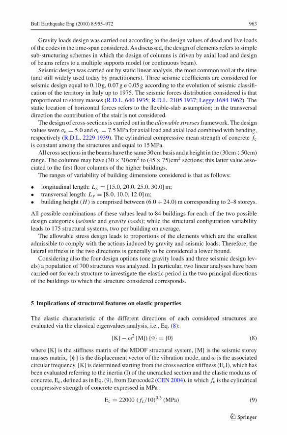
Gravity loads design was carried out according to the design values of dead and live loadsof the codes in the time-span considered. As discussed, the design of elements refers to simplesub-structuring schemes in which the design of columns is driven by axial load and designof beams refers to a multiple supports model (or continuous beam).
Seismic design was carried out by static linear analysis, the most common tool at the time(and still widely used today by practitioners). Three seismic coefficients are considered forseismic design equal to 0.10 g, 0.07 g e 0.05 g according to the evolution of seismic classifi-cation of the territory in Italy up to 1975. The seismic forces distribution considered is thatproportional to storey masses (R.D.L. 640 1935; R.D.L. 2105 1937; Legge 1684 1962). Thestatic location of horizontal forces refers to the flexible-slab assumption; in the transversaldirection the contribution of the stair is not considered.
The design of cross-sections is carried out in the allowable stresses framework. The designvalues were σc = 5.0 and σc = 7.5 MPa for axial load and axial load combined with bending,respectively (R.D.L. 2229 1939). The cylindrical compressive mean strength of concrete fc
is constant among the structures and equal to 15 MPa.All cross sections in the beams have the same 30 cm basis and a height in the (30cm÷50cm)
range. The columns may have (30 × 30)cm2 to (45 × 75)cm2 sections; this latter value asso-ciated to the first floor columns of the higher buildings.
The ranges of variability of building dimensions considered is that as follows:
• longitudinal length: Lx = [15.0, 20.0, 25.0, 30.0] m;• transversal length: L y = [8.0, 10.0, 12.0] m;• building height (H ) is comprised between (6.0 ÷ 24.0) m corresponding to 2–8 storeys.
All possible combinations of these values lead to 84 buildings for each of the two possibledesign categories (seismic and gravity loads); while the structural configuration variabilityleads to 175 structural systems, two per building on average.
The allowable stress design leads to proportions of the elements which are the smallestadmissible to comply with the actions induced by gravity and seismic loads. Therefore, thelateral stiffness in the two directions is generally to be considered a lower bound.
Considering also the four design options (one gravity loads and three seismic design lev-els) a population of 700 structures was analyzed. In particular, two linear analyses have beencarried out for each structure to investigate the elastic period in the two principal directionsof the buildings to which the structure considered corresponds.
5 Implications of structural features on elastic properties
The elastic characteristic of the different directions of each considered structures areevaluated via the classical eigenvalues analysis, i.e., Eq. (8):
[K] − ω2 [M]) {ϕ} = {0} (8)
where [K] is the stiffness matrix of the MDOF structural system, [M] is the seismic storeymasses matrix, {φ} is the displacement vector of the vibration mode, and ω is the associatedcircular frequency. [K] is determined starting from the cross section stiffness (EcI), which hasbeen evaluated referring to the inertia (I) of the uncracked section and the elastic modulus ofconcrete, Ec, defined as in Eq. (9), from Eurocode2 (CEN 2004), in which fc is the cylindricalcompressive strength of concrete expressed in MPa .
Ec = 22000 ( fc/10)0.3 (MPa) (9)
123

964 Bull Earthquake Eng (2010) 8:955–972
The storey masses in the diagonal [M] matrix have been evaluated according to Eurocode8 based on the analysis of dead and live loads for the structure for which the elastic periodsare evaluated.
From Eq. 8 the ωi , {φ}i , and m∗i , associated to the i-th mode defined as the effective mass
and evaluated as:
m∗i =
∑mk φ
k,i(10)
where mk is the seismic mass of the k-th storey, φk,i is the displacement of the k-th floor inthe i-th mode.
The periods considered are those corresponding only to the fundamental modes, primar-ily translational, associated to the principal directions of the structure. Therefore, for eachof the two directions the fundamental {φ}, ω, and m∗ parameters are determined and thecorresponding elastic period, Tel, is defined as:
Tel = 2π
ω(11)
T = 0.135H0.67
T = 0.076H0.93
0.00
0.25
0.50
0.75
1.00
1.25
1.50
1.75
0 3 6 9 12 15 18 21 24 27 30
Height, H [m]
Elastic period, Tel [sec]
transverse
longitudinal
(a)
T = 0.091H0.79
T = 0.112H0.69
0.00
0.25
0.50
0.75
1.00
1.25
1.50
1.75
0 3 6 9 12 15 18 21 24 27 30
Height, H [m]
Elastic period, Tel [sec]
transverse
longitudinal
(b)
T = 0.098H0.75
T = 0.118H0.66
0.00
0.25
0.50
0.75
1.00
1.25
1.50
1.75
0 3 6 9 12 15 18 21 24 27 30
Height, H [m]
Elastic period, Tel [sec]
transverse
longitudinal
(c)
T = 0.107H0.70
T = 0.118H0.65
0.00
0.25
0.50
0.75
1.00
1.25
1.50
1.75
0 3 6 9 12 15 18 21 24 27 30
Height, H [m]
Elastic period, Tel [sec]
transverse
longitudinal
(d)
Fig. 5 Period-height relationships for the analyzed populations: a gravity-loads design, b seismic design(0.05 g), c seismic design (0.07 g) and d seismic design (0.10 g)
123

Bull Earthquake Eng (2010) 8:955–972 965
Figure 5 shows the trends of the periods as a function of the height for the four categoriesof buildings investigated. As expected the design options affect the elastic periods. In fact,those corresponding to gravity loads design are generally smaller than those of structures pro-portioned to resist also to horizontal force, among which to the higher reference accelerationcorresponds to the lower natural periods. Moreover, the longitudinal direction is generallystiffer than the transverse, although the transverse to longitudinal period ratio is larger in thecase of design for gravity loads with respect to seismic.
5.1 Gravity loads designed buildings
In these structures, the period in the short direction is more variable with respect to the longi-tudinal one at a given height. This depends on the particular structural configuration, Fig. 4a,which significantly affects, the ratio between effective mass m∗ and lateral stiffness, Kel, ofthe building. In fact, in Fig. 6, the trends of these quantities are given as a function of theheight for the two directions.
The effective mass relates almost linearly with the height, and it is variable in both direc-tions because of the ranges of global dimensions considered, Lx and L y , which lead to a widerange of plan areas for the populations analyzed, as can be observed in Fig. 7a. In general,the buildings feature effective masses similar in the two directions, therefore the differencesin elastic periods depend on the different lateral stiffness.
As observed in Fig. 6, the long direction has lateral stiffness larger than that in the shortdirection; this discrepancy increases with height and is up to 50% for buildings with morethan 3 storeys. Vice-versa, the longitudinal direction has a larger variability of stiffness withrespect to the transversal one. This has to be attributed to the different lateral resisting systemof the two directions (Fig. 4a).
The stair sub-structure significantly affects the stiffness in the short direction. Despite thefact that this direction has only the two frames on the perimeter, this is magnified in buildingswith three storey or less (H equal or less than 9 m), for which the transverse stiffness inslarger than the longitudinal. The stair module effect, rapidly decreases with height.
The variability of the area covered by the buildings is differently reflected in the elas-tic properties of the two directions (Fig. 7b). In the longitudinal direction the increaseof Lx implies an increase in the number of bays, while an increase in L y leads to anincrease in the number of longitudinal frames. Therefore, the longitudinal direction hasan increasing stiffness with area. Vice versa, the resisting system in the transversal direc-tion is only marginally affected by an increase in the area. In fact, it does not implymodification in the stair module and the slight trend observed is due to the variationof number of bays and of the proportions of the elements of the two frames on theperimeter.
It may be concluded that for gravity loads buildings, the stair module plays a determinantrole in the determination of the transversal period. The lower stiffness in the short directionwith respect to the longer and its comparatively small variability given height clarify thetrend of the period reported in Fig. 5a.
5.2 Seismic buildings
Seismic buildings have a resisting system also in the transversal direction and are alsocharacterized by a more uniform distribution of structural sub-systems, e.g., Fig. 4b. This isreflected in different trends of stiffness with respect to gravity loads designed buildings.
123

966 Bull Earthquake Eng (2010) 8:955–972
0
200
400
600
800
1000
1200
1400
1600
1800
0 3 6 9 12 15 18 21 24 27 30
Mass [tons]
Height, H [m]
(Lx·
L y)
(a)
0
200
400
600
800
1000
1200
1400
1600
1800
0 3 6 9 12 15 18 21 24 27 30
Mass [tons]
Height, H [m]
(Lx·
L y)
(b)
0
20000
40000
60000
80000
100000
120000
140000
160000
0 3 6 9 12 15 18 21 24 27 30
Elastic stiffness, Kel [kN/m]
Height, H [m]
(c)
0
20000
40000
60000
80000
100000
120000
140000
160000
0 3 6 9 12 15 18 21 24 27 30
Elastic stiffness, Kel [kN/m]
Height, H [m]
(d)
Fig. 6 Gravity-loads design: a transverse elastic stiffness versus height; b longitudinal elastic stiffness versusheight; c transverse effective mass versus height; d longitudinal effective mass versus height
0
200
400
600
800
1000
1200
0 100 200 300 400
Mass [tons]
Plan area, S [m2]
transverse
longitudinal
(a)
0
10000
20000
30000
40000
50000
60000
70000
80000
0 100 200 300 400
Elastic stiffness, Kel [kN/m]
Plan area, S [m2]
transverse
longitudinal
(b)
Fig. 7 Effective mass (a) and elastic stiffness (b) versus area for a 15.0 m buildings designed for gravity loadsonly
123

Bull Earthquake Eng (2010) 8:955–972 967
0
20000
40000
60000
80000
100000
120000
140000
160000
180000
0 5 10 15 20 25 30
Height, H [m]
Elastic stiffness, Kel [kN/m]
(a)
0
20000
40000
60000
80000
100000
120000
140000
160000
180000
0 5 10 15 20 25 30
Height, H [m]
Elastic stiffness, Kel [kN/m]
(b)
0
20000
40000
60000
80000
100000
120000
140000
160000
180000
0 5 10 15 20 25 30
Height, H [m]
Elastic stiffness, Kel [kN/m]
(c)
0
20000
40000
60000
80000
100000
120000
140000
160000
180000
0 5 10 15 20 25 30
Height, H [m]
Elastic stiffness, Kel [kN/m]
(d)
0
20000
40000
60000
80000
100000
120000
140000
160000
180000
0 5 10 15 20 25 30
Height, H [m]
Elastic stiffness, Kel [kN/m]
(e)
0
20000
40000
60000
80000
100000
120000
140000
160000
180000
0 5 10 15 20 25 30
Height, H [m]
Elastic stiffness, Kel [kN/m]
(f)
Fig. 8 Elastic stiffness versus height in transverse (left) and longitudinal (right) directions for seismicbuildings with seismic coefficients of 0.05 g (a, b), 0.07 g (c, d), 0.10 g (e, f)
123

968 Bull Earthquake Eng (2010) 8:955–972
In Fig. 8 the stiffness as a function of height is given for the two directions of the threeseismic categories considered. The stiffness in the two directions is similar. In fact, thestiffness in the longitudinal direction is never larger than 20% more with respect to thetransversal direction. In particular, two storey buildings have a stiffness that is constant, onaverage, with respect to the design acceleration. The moderate height leads to actions thatcan be taken by the minimum proportions of structural elements. Therefore, the structuresresult generally similar independently of the design acceleration. Moreover, for this kind ofbuildings the stiffness reduces with global height in both directions and variability is alsocomparable. The more uniform distribution of resisting systems with respect to the gravityloads designed is also reflected in a different trend of stiffness as a function of plan areawhich now affects also the transversal direction. In Fig. 9a and b Kel is given for the twodirections of buildings with H equal to 15.0 m and designed for 0.05 and 0.10 g, respectively.
Seismic designed buildings are generally stiffer that those designed for gravity loads only.In Fig. 10 the ratio of the average seismic to gravity loads stiffness is given for the twodirections. This ratio increases in the transversal direction while it is almost constant in the
0
10000
20000
30000
40000
50000
60000
70000
80000
0 100 200 300 400
Elastic stiffness, Kel [kN/m]
Plan area, S [m2]
transverse
longitudinal
(a)
0
10000
20000
30000
40000
50000
60000
70000
80000
0 100 200 300 400
Elastic stiffness, Kel [kN/m]
Plan area, S [m2]
transverse
longitudinal
(b)
Fig. 9 Seismic buildings: elastic stiffness versus area for a 15 m building designed with acceleration equal to0.05 g (a) and 0.10 g (b)
1.00
1.20
1.40
1.60
1.80
2.00
2.20
2.40
0 3 6 9 12 15 18 21 24 27 30
0.05g0.07g0.10g
Height, H [m]
(Kelseismic/ Kel
gravity)
(a)
1.00
1.20
1.40
1.60
1.80
2.00
2.20
2.40
0 3 6 9 12 15 18 21 24 27 30
0.05g0.07g0.10g
Height, H [m]
(Kelseismic/ Kel
gravity)
(b)
Fig. 10 Average seismic to gravity elastic stiffness ratio in a transverse and b longitudinal direction
123

Bull Earthquake Eng (2010) 8:955–972 969
longitudinal. This is mainly because the different structural systems affects more the formerdirection rather than the latter. The plane frames added in the seismic design contribute tothe stiffness in an increasing manner with respect to the height of the building.
In the longitudinal direction, an increase in the design accelerations also implies a incre-ment in the stiffness leading, on average, to a ratio with respect to the gravity loads designcase of 1.25, 1.35, and 1.45 for 0.05, 0.07, and 0.10 g. In the transverse direction, 20% isthe minimum stiffness increment, a number found for the two storey buildings, while 95%is scored by eight storey buildings, corresponding to the maximum global height consideredin the study, and designed for 0.10 g. These results are reflected in the trends of Fig. 5b–d.
6 Period predictors from regression analysis
Although it is not an experimental sample, simple regression analysis on the analyzed popu-lations allows one to see how results in terms of fundamental period display with respect toheight. For comparative purposes, the same power-law formulation of Eq. (1) was assumedand the coefficients were estimated via ordinary least square regression.
For the case of gravity loads design the relationships for transverse and longitudinal direc-tions are, respectively:
Tel = 0.076H0.93 Tel = 0.135H0.67 (12)
Moreover, for the transverse direction, the same relationship was retrieved also not con-sidering the contribution of stair sub-structure, Eq. (13).
Tel = 0.105H0.94 (13)
Analogous relationships were determined for the three populations of seismic buildings:seismic coefficient 0.05 g
Tel = 0.091H0.79 Tel = 0.112H0.69 (14)
seismic coefficient 0.07 g
Tel = 0.098H0.75 Tel = 0.118H0.66 (15)
seismic coefficient 0.10 g
Tel = 0.107H0.70 Tel = 0.118H0.65 (16)
Figure 11 serves to compare the relationships found for the two considered directions.The trends generally reflect what observed for stiffness. The largest periods is observed forgravity-loads designed buildings while it decreases if the design acceleration is increased. Inthe longitudinal direction the period of seismic buildings is lower by 10–20% with respect togravity loads. In the transversal direction, the reduction in period or seismic buildings maybe as large as 45% for the eight storey buildings.
Comparing the period-height relationship including and not-including the stair modulefor gravity loads design buildings, the contribution of the sub-structure may be appreciatedas the stair leads to a reduction of the latter as large as 40%.
Finally, only as a reference, the Eurocode 8 (CEN 2005) period-height curve is also givenin the figure. The Eurocode 8 period is systematically lower than that found because it isa lower bound already (Goel and Chopra 1997) and also because it is expected to refer tobuildings featuring a different design philosophy.
123

970 Bull Earthquake Eng (2010) 8:955–972
0.00
0.50
1.00
1.50
2.00
2.50
0 3 6 9 12 15 18 21 24 27 30
Height, H [m]
Elastic period, Tel [sec]
EC8,2004
0.10g0.07g
0.05g
gravity with stairsgravity w/o stairs
(a)
0.00
0.50
1.00
1.50
2.00
2.50
0 3 6 9 12 15 18 21 24 27 30
Height, H [m]
Elastic period, Tel [sec]
EC8,2004
0.10g
0.07g
0.05g
gravity
(b)
Fig. 11 Comparison of period-height relationships for the buildings analyzed in the transverse (a) and longi-tudinal (b) directions
Because Figs. 7 and 9, show that the effective mass and translational stiffness is alsocorrelated with the plan extension of the building, it is expected that this variable has someprediction power with respect to the period. Therefore, an expression which includes alsothe plan area is considered Eq. (17):
T = αHβ Sγ (17)
where S is the product of the two principal plan dimensions of the building Lx and L y . Forthe case of gravity loads design, least squares regression leads to the relationships for thetransversal and longitudinal directions, respectively, given in Eq. (18):
Tel = 0.009H0.93S0.39 Tel = 0.044H0.67S0.21 (18)
the same kind of analysis for the seismic directions provides:seismic coefficient 0.05 g
Tel = 0.029H0.79S0.21 Tel = 0.059H0.69S0.14 (19)
seismic coefficient 0.07 g
Tel = 0.033H0.75S0.20 Tel = 0.062H0.66S0.12 (20)
seismic coefficient 0.10 g
Tel = 0.039H0.70S0.19 Tel = 0.068H0.65S0.10 (21)
How much S contributes to explain the period is assessed simply analyzing the standarderror for the regressions’ residuals, σT :
σT =√√√√
[n∑
i=1
(log T − log Ti
)2
]/(n − 1) (22)
In Eq. (22) T is the period from the regression model for the building having the computedvalue Ti and n is the size of the sample. In Table 1 the values of σT for all cases analyzed arereported, for the two conditions with and without the plan dimension factor, S. The results
123

Bull Earthquake Eng (2010) 8:955–972 971
Table 1 Standard error for the regressions’ residuals
Design type Direction Standard error, σT
T = αHβ T =αHβ Sγ
Gravity Transverse 0.131 0.051
Longitudinal 0.078 0.045
seismic 0.05g Transverse 0.086 0.055
Longitudinal 0.072 0.058
Seismic 0.07g Transverse 0.082 0.051
Longitudinal 0.066 0.055
Seismic 0.10g Transverse 0.073 0.044
Longitudinal 0.059 0.050
lead one to conclude that S adds information on the period for gravity loads design onlyas for this building typology, adding S leads to a 60% reduction in the standard error withrespect to the formulation which only accounts for the height.
7 Conclusions
The elastic period has a primary role in the seismic design and assessment of buildings.Many codes propose simplified equations, retrieved on semi-empirical basis, expressing thefundamental period as a function of height, which represents the relationship between massand stiffness of the structure. Nevertheless, the majority of these relationships are based ondata of buildings reflecting seismic design criteria very different from those of the Europeanexisting structures.
In the study presented herein, two populations of typical Euro-Mediterranean reinforcedconcrete buildings have been investigated: the first one being designed for gravity loads only,the second one designed with obsolete seismic design criteria. The structures considered arebare-frames and assumed to be restrained at the base.
Modal analyses allowed to assess the influence of design criteria, structural system andglobal dimensions (area and height) on the elastic stiffness, the effective mass, and the elasticperiod for both principal axes of the buildings to be assessed. The results are different for thetwo classes:
• Gravity load designed buildings feature periods in the two directions which have anincreasing difference with height that can be as large as 50%. The period shows largevariability in the short direction due to the variability of plan area.
• Seismic designed buildings show a lower period in the longitudinal direction with respectto the corresponding gravity load buildings; this reduction, obviously, increases withdesign acceleration and is up to 20%. In the short direction the reduction of fundamentalperiod is more significant (50%) because it is due not only to different design criteria, butalso (mainly) to the different structural system.
Finally, based on the results of the analyses a power-law regression was carried out as afunction of height. In the comparison with Eurocode 8 formulas existing buildings showsystematically larger periods for those herein analyzed. In particular, gravity loads designed
123

972 Bull Earthquake Eng (2010) 8:955–972
buildings, featuring a 3D structural system, seem to require a twofold definition of periodreferring to the two directions. Therefore, height alone seems inadequate to explain periodvariability and the results of this study suggest that. Also a global parameter (e.g., plan area)should be added in simplified relationships for rapid period evaluation.
Acknowledgments This work was supported by the Italian Dipartimento della Protezione Civile as part ofthe 2005–2008 ReLUIS project.
References
Applied Technological Council (1978) Tentative provisions for the development of seismic regulation forbuildings. Rep. No, ATC3-06, Applied Technological Council, Palo Alto
Bal IE, Crowley H, Pinho R, Gulay FG (2007) Structural characteristics Of Turkish RC building stock innorthern Marmara region for loss assessment applications. IUSS Press, Pavia
CEN (2004) Eurocode 2: design of concrete structures—part 1–1: general rules and rules for buildings.European Prestandard ENV 1992-1-1. Comite European de Normalisation, Brussels
CEN (2005) Eurocode 8: design provisions for earthquake of structures—part 1–4: strengthening and repairof buildings. European Prestandard ENV 1998-1-4. Comite European de Normalisation, Brussels
Chopra AK (1995) Dynamics of structures: theory and applications to earthquake engineering. Pretince-Hall,Upper Saddle River
Cosenza E, Manfredi G, Verderame GM (2002) Seismic assessment of gravity loads designed r.c. frames:critical issues in structural modeling. J Earthq Eng 6(1):101–122
Crowley H, Pinho R (2004) Period-height relationship for existing European reinforced concrete buildings.J Earthq Eng 8(1):93–119
Crowley H, Pinho R (2009) Revisiting Eurocode 8 formulae for periods of vibration and their employment inlinear seismic analysis. Earthq Eng Struct Dyn. doi:10.1002/eqe.949 (in press)
D.M. n 1684 (1975) Approvazione delle norme tecniche per le costruzioni in zone sismiche (in italian)Goel RK, Chopra AK (1997) Period formulas for moment-resisting frame buildings. Struct Eng Div ASCE
123:1454–1461Hong L, Hwang W (2000) Empirical formula for fundamental vibration periods of reinforced concrete build-
ings in Taiwan. Earthq Eng Struct Dyn 29:327–333Legge n 1684 (1962) Provvedimenti per l’edilizia, con particolari prescrizioni per le zone sismiche (in Italian)NEHRP (1994) Recommended provisions for the development of seismic regulations for new buildings. Build-
ing Seismic Safety Council, Washington, DCR.D.L. n 2105 (1937) Norme tecniche di edilizia con speciali prescrizioni per le località colpite dai terremoti
(in Italian)R.D.L. n 640 (1935) Norme tecniche di edilizia con speciali prescrizioni per le località colpite dai terremoti
(in Italian)R.D.L. n 2229 (1939) Norme per la esecuzione delle opere in conglomerate cementizio semplice od armato
(in Italian)SEAOC (1996) Recommended lateral force requirements and commentary. Seismological Engineers Associ-
ation of California, San FranciscoUBC-Uniform Building Code (1997) International conference of building officials. Whittier, CAVerderame GM, Polese M, Mariniello C, Manfredi G (2010) A simulated design procedure for the assessment
of seismic capacity of existing RC buildings. Adv Eng Softw 41(2):323–335Verderame GM, Polese M, Cosenza E (2009) Vulnerability of existing RC buildings under gravity loads: A
simplified approach for non sway structures. Eng Struct 31(9):2141–2151
123