Embed Size (px)
Citation preview
Elastic and acoustic characterisation ofanisotropic porous materials
Remi Guastavino
Doctoral Thesis
TRITA-AVE 2008-25ISSN 1651-7660
ISBN 978-91-7178-995-2
Stockholm 2008Kungliga Tekniska Hogskolan
Department of Aeronautical and Vehicle EngineeringThe Marcus Wallenberg Laboratory for Sound and Vibration Research
Postal address Visiting address Contact
Royal Institute of Technology Teknikringen 8 Tel: +46 70 4711 450MWL / AVE Stockholm Email:[email protected] 44 Stockholm

“Kan du se, hvad jeg hører?”
(Can you see what I hear?)
K. D. Mortensen, Danish saxophonist & composer.

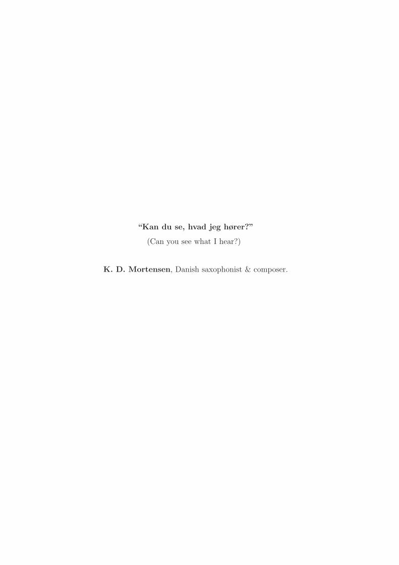
Abstract
For an accurate prediction of the low and medium frequency surface vibrationand sound radiation behaviour of porous materials, there is a need to improvethe means of estimating their elastic and acoustic properties. The underlyingreasons for this are many and of varying origin, one prominent being a poorknowledge of the geometric anisotropy of the cell microstructure in the manu-factured porous materials. Another one being, the characteristic feature of suchmaterials i.e. that their density, elasticity and dissipative properties are highlydependent upon the manufacturing process techniques and settings used. In thecase of free form moulding, the geometry of the cells and the dimensions of thestruts are influenced by the rise and injection flow directions and also by the effectof gravity, elongating the cells. In addition the influence of the boundaries of themould also introduces variations in the properties of the foam block produced.Despite these complications, the need to predict and, in the end, optimise theacoustic performance of these materials, either as isolated components or as partof a multi-layer arrangement, is growing. It is driven by the increasing demandsfor an acoustic performance in balance with the costs, a focus which serves to in-crease the need for modelling their behaviour in general and the above mentioned,inherent, anisotropy in particular.
The current work is focussing on the experimental part of the characterisationof the material properties which is needed in order to correctly represent theanisotropy in numerical simulation models. Then an hybrid approach based ona combination of experimental deformation, strain field mapping, flow resistivitymeasurement and physically based porous material acoustic Finite Element (FE)simulation modelling is described. This inverse estimation linked with high qual-ity measurements is crucial for the determination of the anisotropic coefficients ofthe porous materials is illustrated here for soft foam and fibrous wool materials.

Dissertation
The thesis consists of an introduction and five appendixed papers:
Paper A
Remi Guastavino & Peter GoranssonA 3D deformation measurement methodology for anisotropic porous cellular foammaterials, March 2007.in Polymer Testing, Elsevier Science.
Paper B
Peter Goransson, Remi Guastavino & Nils-Erik HorlinA 3D anisotropic flow resistivity measurement method for fibrous wool materials,March 2008.Submitted to The Journal of the Acoustical Society of America
Paper C
Remi Guastavino, Peter Goransson & Nils-Erik HorlinA 3D anisotropic flow resistivity estimation for soft porous foam, April 2008.Submitted to The Journal of Sound and Vibration
Paper D
Remi Guastavino & Peter GoranssonA methodology for identification of general orthotropic elastic models of porousfoam, May 2008.To be submitted to Computational Mechanics
Paper E
Peter Goransson & Remi GuastavinoIdentification of a general orthotropic, viscoelastic model of a porous foam, May2008.To be submitted to Computer Methods in Applied Mechanics and Engineering
Partition of works between authors
The work in the papper were shared between the authors:
Paper A
Guastavino developed the measurement principle.Guastavino designed the experimental setup and performed the measurement.Both the authors were involved in the writing of the paper.
Paper B
Guastavino, Goransson and Horlin developed the measurement principle.Guastavino designed the experimental setup and performed the measurement.Goransson developed the FE model and the inverse estimation procedure.All the authors were involved in the writing of the paper.
Paper C
Guastavino, Goransson and Horlin developed the measurement principle.Guastavino designed the experimental setup and performed the measurement.Goransson developed the FE model and the inverse estimation procedure.All the authors were involved in the writing of the paper.
Paper D
Guastavino designed the experimental setup and performed the measurement.Goransson developed the FE model and the inverse estimation procedure.Both the authors were involved in the writing of the paper.
Paper E
Guastavino designed the experimental setup and performed the measurement.Goransson developed the FE model and the inverse estimation procedure.Both the author were involved in the writing of the paper.
CONTENTS 1
Contents
1 Introduction 1
2 Anisotropy in porous cellular materials 3
3 Related work 5
4 Scope of the present work 7
5 Measurement methodology 9
5.1 Measurement methodology for elastic moduli . . . . . . . . . . . . 95.2 New measurement methodology for elastic moduli . . . . . . . . . 115.3 Measurement methodology for viscoelastic moduli . . . . . . . . . 125.4 Novel measurement for static flow . . . . . . . . . . . . . . . . . . 14
6 Inverse estimation 15
7 Conclusion and future Work 16
8 Acknowledgements 17
Paper A
Paper B
Paper C
Paper D
Paper E

1 Introduction 1
1 Introduction
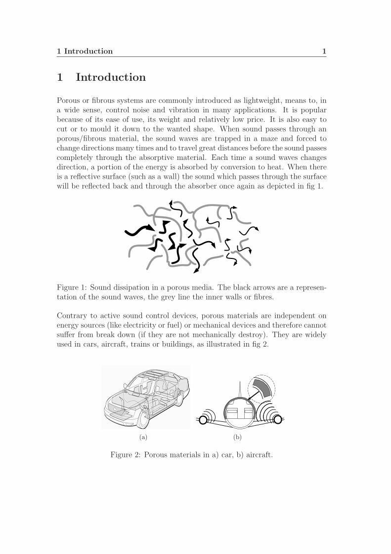
Porous or fibrous systems are commonly introduced as lightweight, means to, ina wide sense, control noise and vibration in many applications. It is popularbecause of its ease of use, its weight and relatively low price. It is also easy tocut or to mould it down to the wanted shape. When sound passes through anporous/fibrous material, the sound waves are trapped in a maze and forced tochange directions many times and to travel great distances before the sound passescompletely through the absorptive material. Each time a sound waves changesdirection, a portion of the energy is absorbed by conversion to heat. When thereis a reflective surface (such as a wall) the sound which passes through the surfacewill be reflected back and through the absorber once again as depicted in fig 1.
Figure 1: Sound dissipation in a porous media. The black arrows are a represen-tation of the sound waves, the grey line the inner walls or fibres.
Contrary to active sound control devices, porous materials are independent onenergy sources (like electricity or fuel) or mechanical devices and therefore cannotsuffer from break down (if they are not mechanically destroy). They are widelyused in cars, aircraft, trains or buildings, as illustrated in fig 2.
(a) (b)
Figure 2: Porous materials in a) car, b) aircraft.
1 Introduction 2
The inherent design parameters available for these materials, i.e. the micro-structural dimensions together with the chosen polymer constituents, open up aninteresting potential in terms of application tailored bulk properties, such as elas-tic, acoustic and dissipative mechanisms. The optimal structural design of porouslayered system materials is one of the central issues in materials science, sincethe shape and the topology of the microstructure have a significant impact onthe macroscopic properties such as the mechanical and thermal behaviour. Theengineering design of new materials is determined by the optimization of specific,applications oriented performance aspects. The performance measure can be cho-sen according to the mode of loading (tension, bending, twisting), with respectto thermal properties (expansion versus normalized strength, thermal shock re-sistance), or by taking into account criteria dictated by technological constraints(minimum weight, vibration damping), or economical considerations (cost of pro-duction). All these performance measures largely depend on the shape both in themicroscopic and macroscopic aspect and on the material properties such as mod-ulus, strength, toughness, and thermal conductivity, diffusivity, and expansion.For an accurate prediction of the low and medium frequency surface vibrationand sound radiation behaviour of porous layered system, improved means of es-timating the elastic and acoustic characterisation of porous layered systems arenecessary. The underlying reasons for this need are many and of varying origin,one prominent being a poor knowledge of the geometric anisotropy of the cell mi-crostructure in the manufactured porous materials. Despite these complications,the need to predict and, in the end, optimise the acoustic performance of thesematerials, either as isolated components or as part of a multi-layer arrangement,is growing. One driving force behind this trend is the increasing pressure tobalance acoustic performance against the cost of these materials in the productdevelopment cycle, a fact which serves to strengthen the need for modelling ingeneral and the inherent anisotropy in particular.
The current work has followed two main routes, one focussing on the experimen-tal part of the characterisation of the material properties which is needed in orderto correctly represent the anisotropy in numerical simulation models and one fo-cussing on the inverse estimation method and the numerical result. The commondenominators are the advanced measurement methodology developed and usedtogether with 3D simulations. For the foam characterisation the overall objectiveis to establish a hybrid approach based on a combination of experimental de-formation, strain field mapping and flow resistivity, and physically based porousmaterial acoustic Finite Element (FE) simulation modelling. Ultimately such amethod will provide the anisotropic coefficients to model the acoustic propertiesof an arbitrary porous layered system.
2 Anisotropy in porous cellular materials 3
2 Anisotropy in porous cellular materials
In manufactured porous or fibrous systems, e.g. of the type found in acoustictrim components for automotive or aerospace applications there exists an inher-ent geometric anisotropy in the layered systems cell microstructure driven by theproduction process. In the case of free form moulding, the geometry of the cellsand the dimensions of the struts are influenced by the rise and injection flowdirections and also by the effect of gravity, elongating the cells. In addition, theinfluence of the boundaries of the mould, also introduce variations in the proper-ties of the foam block produced. The bulk properties, i.e. density, elastic moduliand damping moduli of the porous layered system, can then be considered to behighly dependent upon, and in principle controlled by, the chosen manufactur-ing process techniques, together with the polymer chemical formulations. Themacroscopic properties of commercial available foams are most of the time con-sidered to be isotropic, and are not given (or even known) by manufacturers interms of the material coordinates. Simple measurements show, however, that alarge scale variation may be found depending on the orientation of the material.In order to explore this fact in real porous materials, an open cell melamine foam,a polyurethane foam and glass wool has been studied with the objectives to mapthese properties without assumed symmetries.
- Melamine is a lightweight, high temperature resistant, open cell foam manufac-tured from melamine resin. It combines good thermal properties with efficientsound absorption capabilities to create a fibre free product which can be appliedin situations which may prohibit the use of urethane foams or fibreglass insula-tions.This foam has been used mainly for static and dynamic vibration measurements,as well as an introduction to flow resistivity measurements.
- Glass wool is made from the fusion of a mixture of natural sand and recycledglass at 1 500 C, the glass that is produced is converted into very thin strings ofglass arranged into a spongy texture. Glass wool is used widely as an insulatingmaterial. The cohesion and mechanical strength of the product is obtained bythe presence of a binder that hold the fibres together. Glass wool offers excellentfire-resistant properties, as a thermal insulation material and is also widely usedas an absorbent material in acoustic treatments. Its low weight, flexibility andelasticity make it easy to install, which is another essential condition for effectiveinsulation.Here, it has been used because of its quasi transversal anisotropic properties asan introduction to flow resistivity tensor estimation measurement.
2 Anisotropy in porous cellular materials 4
- Polyurethane foam is often made by adding small amounts of volatile materials,so-called blowing agents, to the reaction mixture. These simple volatile chem-icals yield important performance characteristics, primarily thermal insulation;polyurethane foams are not fireproof and can be hazardous in the event of a firebecause they releases toxic fumes into the air.Here, it has been used for a confirmation of the full flow resistivity tensor esti-mation technique developed as part of the thesis work.
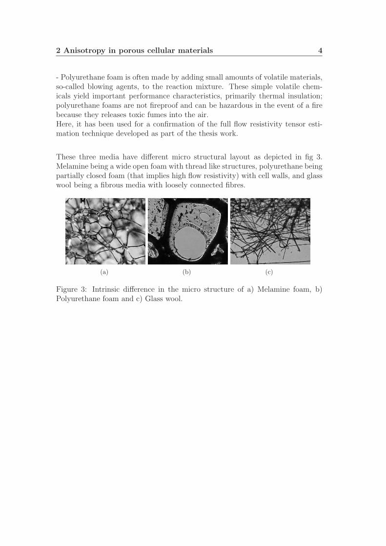
These three media have different micro structural layout as depicted in fig 3.Melamine being a wide open foam with thread like structures, polyurethane beingpartially closed foam (that implies high flow resistivity) with cell walls, and glasswool being a fibrous media with loosely connected fibres.
(a) (b) (c)
Figure 3: Intrinsic difference in the micro structure of a) Melamine foam, b)Polyurethane foam and c) Glass wool.
3 Related work 5
3 Related work
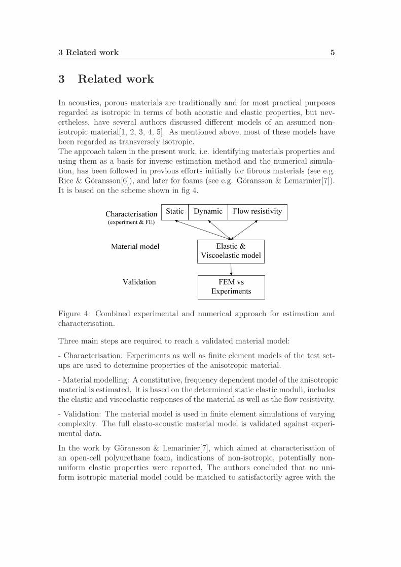
In acoustics, porous materials are traditionally and for most practical purposesregarded as isotropic in terms of both acoustic and elastic properties, but nev-ertheless, have several authors discussed different models of an assumed non-isotropic material[1, 2, 3, 4, 5]. As mentioned above, most of these models havebeen regarded as transversely isotropic.The approach taken in the present work, i.e. identifying materials properties andusing them as a basis for inverse estimation method and the numerical simula-tion, has been followed in previous efforts initially for fibrous materials (see e.g.Rice & Goransson[6]), and later for foams (see e.g. Goransson & Lemarinier[7]).It is based on the scheme shown in fig 4.
Static Dynamic
Elastic & Viscoelastic model
FEM vs Experiments
Characterisation (experiment & FE)
Material model
Validation
Flow resistivity
Figure 4: Combined experimental and numerical approach for estimation andcharacterisation.
Three main steps are required to reach a validated material model:
- Characterisation: Experiments as well as finite element models of the test set-ups are used to determine properties of the anisotropic material.
- Material modelling: A constitutive, frequency dependent model of the anisotropicmaterial is estimated. It is based on the determined static elastic moduli, includesthe elastic and viscoelastic responses of the material as well as the flow resistivity.
- Validation: The material model is used in finite element simulations of varyingcomplexity. The full elasto-acoustic material model is validated against experi-mental data.
In the work by Goransson & Lemarinier[7], which aimed at characterisation ofan open-cell polyurethane foam, indications of non-isotropic, potentially non-uniform elastic properties were reported, The authors concluded that no uni-form isotropic material model could be matched to satisfactorily agree with the
3 Related work 6
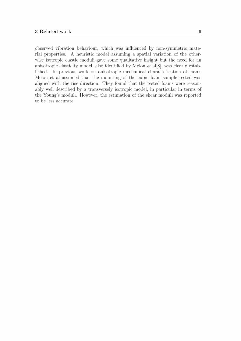
observed vibration behaviour, which was influenced by non-symmetric mate-rial properties. A heuristic model assuming a spatial variation of the other-wise isotropic elastic moduli gave some qualitative insight but the need for ananisotropic elasticity model, also identified by Melon & al[8], was clearly estab-lished. In previous work on anisotropic mechanical characterisation of foamsMelon et al assumed that the mounting of the cubic foam sample tested wasaligned with the rise direction. They found that the tested foams were reason-ably well described by a transversely isotropic model, in particular in terms ofthe Young’s moduli. However, the estimation of the shear moduli was reportedto be less accurate.
4 Scope of the present work 7
4 Scope of the present work
The current work aims at taking a step further towards a precise and reliablematerial model of foams used in noise and vibration treatments. The main con-tributions have been achieved in
• New measurement technology for elastic and static loading, in particular:- The used of a translating device, capable of performing purely vertical,uniaxial motion. Thus, a controlled displacement during compression maybe ascertained, which is an important aspect for the attempted inversemodelling based on FE simulation of the experimental setup, and also gotof problems associated with the non axial load on the load cell (induced bythe anisotropy of the foam) that affected early on the estimated load value.- The used of a 360-degrees rotating table; by precisely rotating the sam-ple it is possible to acquire images of the four faces, without removing theload, with a common reference for the recorded deformations provided bythe vertical reference plates. This has the advantage of reducing the testingtime required as well as increasing the precision in the measured data.- The introduction of the lateral reference plates. These plates were foundto be necessary because of the rotation of the sample on the table, dur-ing which an error of a fraction of a degree in the rotational angle is hardto avoid and which substantially influences the measured out-of-plane dis-placement.- The observations of boundary effects at material discontinuities. Foamdisplacements in the direction of the applied compression are high in theregions close to the interfaces between the foam sample and the referenceplates, independently to the compression ratio.
• New measurement technology for static flow resistivity, in particular:- The conception and design of the aluminium cubic sample holder with sixindividually closable openings (one on each face) and with the inner wallsrecover with a soft closed foam that prevent air to travel along the walls.This device allowed measurements in the 3 main directions without havingto extract cylindrical samples. It avoids the cylindrical cutting which tendsto lead to large edge deformations for soft foams and also damage to the in-ner skeleton or the membranes. Note also that the standard cylindrical testdoes not truly measure σxx etc., unless the directions for which the cylin-drical samples are extracted coincide with the principal material directions.The new method is shown to be more accurate and repeatable as comparedto the standard measurement due to the intrinsic physical structure andcharacteristic of the studied materials.

4 Scope of the present work 8
• Inverse estimation of model parameters, in particular:- The inverse estimation of the full, anisotropic flow resistivity tensor forporous foam or Glass wool, with principal directions. This method is fastand simple to use and is built on the static flow resistivity measurementmethodology.- The determination of constitutive models for elasticity and dynamic be-haviour in foams, in particular the elastic modulus matrix and the transfor-mation angles specified to properly represent the elastic properties of thematerial tested in the body coordinate system.

5 Measurement methodology 9
5 Measurement methodology
In order to determine an elasto-acoustic material model of a porous medium,Experimental data have been recorded for 3D flow resistivity measurements:
• the elastic moduli measured and estimated from deformation under staticcompression using CCD cameras and photogrammetry[9, 10].
• dynamic measurement are carried out to provide a set of data for estimationof viscoelastic properties (in vacuo moduli)
• 3D flow resistivity measurements.
5.1 Measurement methodology for elastic moduli
For the elastic moduli, special care has to be exercised on foam in order to managethe stress relaxation under a constant strain. Experiment were performed usingthe setup shown in fig 5. It was found that the recorded force was highly time
Load cell
Computer
Fixed plate
Foam
Applied deformation
Figure 5: Experimental setup for static modulus determination.
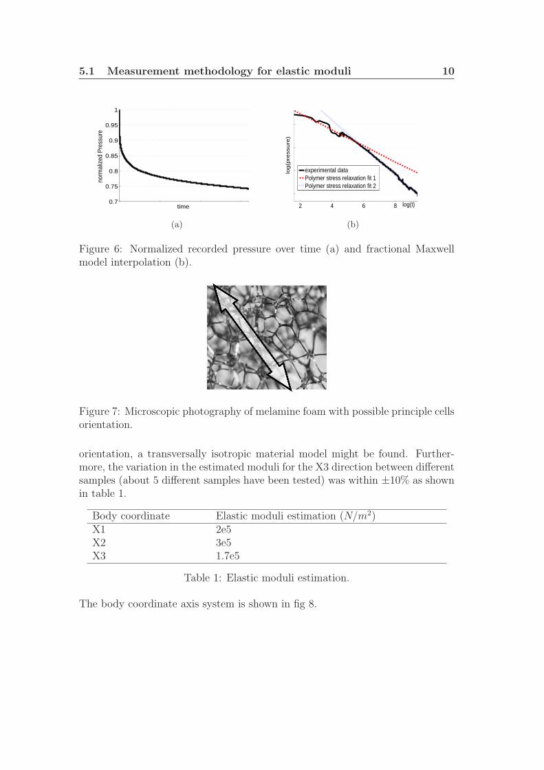
dependent due to the material relaxation. The pressure (force applied per unitarea) is described as a function of time in fig 6. The static moduli were thenestimated through a fractional Maxwell model[11], in which the stress appears asa non-integer order derivative of the strain. Two non-integer values were used,one for short time that is close to zero (behaviour close to the ideal elastic solid),and one longer (plastic-like) as shown in fig 6
The microstructure of the Melamine foam that was studied in the measurementsis exemplified in fig 7.
These first results clearly indicated that the samples tested were anisotropic,although exhibiting almost equal moduli in two different directions (±15% dif-ference). This proximity suggests that for some properly chosen material system
5.1 Measurement methodology for elastic moduli 10
0.7
0.75
0.8
0.85
0.9
0.95
1
time
norm
aliz
ed P
ress
ure
(a)
2 4 6 8 log(t)
log
(pre
ssu
re)
experimental dataPolymer stress relaxation fit 1Polymer stress relaxation fit 2
(b)
Figure 6: Normalized recorded pressure over time (a) and fractional Maxwellmodel interpolation (b).
Figure 7: Microscopic photography of melamine foam with possible principle cellsorientation.
orientation, a transversally isotropic material model might be found. Further-more, the variation in the estimated moduli for the X3 direction between differentsamples (about 5 different samples have been tested) was within ±10% as shownin table 1.
Body coordinate Elastic moduli estimation (N/m2)X1 2e5X2 3e5X3 1.7e5
Table 1: Elastic moduli estimation.
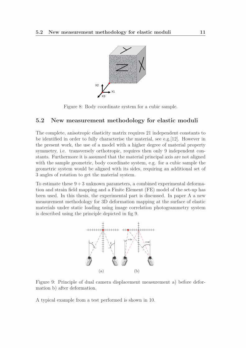
The body coordinate axis system is shown in fig 8.
5.2 New measurement methodology for elastic moduli 11
X1
X2
X3
Figure 8: Body coordinate system for a cubic sample.
5.2 New measurement methodology for elastic moduli
The complete, anisotropic elasticity matrix requires 21 independent constants tobe identified in order to fully characterise the material, see e.g.[12]. However inthe present work, the use of a model with a higher degree of material propertysymmetry, i.e. transversely orthotropic, requires then only 9 independent con-stants. Furthermore it is assumed that the material principal axis are not alignedwith the sample geometric, body coordinate system, e.g. for a cubic sample thegeometric system would be aligned with its sides, requiring an additional set of3 angles of rotation to get the material system.
To estimate these 9+3 unknown parameters, a combined experimental deforma-tion and strain field mapping and a Finite Element (FE) model of the set-up hasbeen used. In this thesis, the experimental part is discussed. In paper A a newmeasurement methodology for 3D deformation mapping at the surface of elasticmaterials under static loading using image correlation photogrammetry systemis described using the principle depicted in fig 9.
α β
(a)
α+∆αβ+∆β
(b)
Figure 9: Principle of dual camera displacement measurement a) before defor-mation b) after deformation.
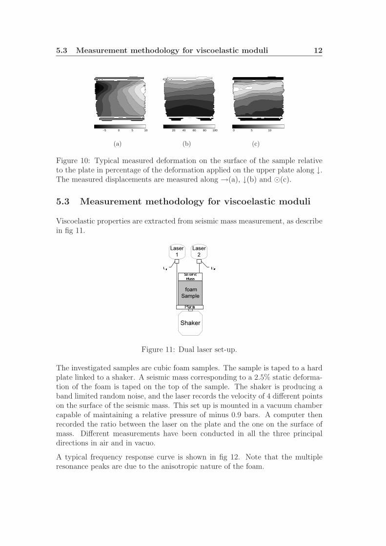
A typical example from a test performed is shown in 10.
5.3 Measurement methodology for viscoelastic moduli 12
−5 0 5 10
(a)
20 40 60 80 100
(b)
0 5 10
(c)
Figure 10: Typical measured deformation on the surface of the sample relativeto the plate in percentage of the deformation applied on the upper plate along ↓.The measured displacements are measured along →(a), ↓(b) and ⊙(c).
5.3 Measurement methodology for viscoelastic moduli
Viscoelastic properties are extracted from seismic mass measurement, as describein fig 11.
foamSample��������������
Shaker
Laser2 �Laser
1 �
Figure 11: Dual laser set-up.
The investigated samples are cubic foam samples. The sample is taped to a hardplate linked to a shaker. A seismic mass corresponding to a 2.5% static deforma-tion of the foam is taped on the top of the sample. The shaker is producing aband limited random noise, and the laser records the velocity of 4 different pointson the surface of the seismic mass. This set up is mounted in a vacuum chambercapable of maintaining a relative pressure of minus 0.9 bars. A computer thenrecorded the ratio between the laser on the plate and the one on the surface ofmass. Different measurements have been conducted in all the three principaldirections in air and in vacuo.
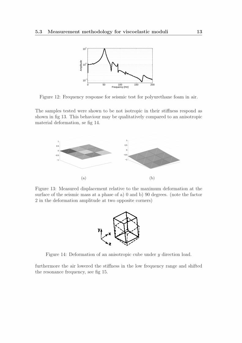
A typical frequency response curve is shown in fig 12. Note that the multipleresonance peaks are due to the anisotropic nature of the foam.
5.3 Measurement methodology for viscoelastic moduli 13
0 50 100 150 200
10−1
100
101
Frequency [Hz]
Am
plitu
de
Figure 12: Frequency response for seismic test for polyurethane foam in air.
The samples tested were shown to be not isotropic in their stiffness respond asshown in fig 13. This behaviour may be qualitatively compared to an anisotropicmaterial deformation, se fig 14.
−1
−0.5
0
0.5
1
(a)
−1
−0.5
0
0.5
1
(b)
Figure 13: Measured displacement relative to the maximum deformation at thesurface of the seismic mass at a phase of a) 0 and b) 90 degrees. (note the factor2 in the deformation amplitude at two opposite corners)
Figure 14: Deformation of an anisotropic cube under y direction load.
furthermore the air lowered the stiffness in the low frequency range and shiftedthe resonance frequency, see fig 15.
5.4 Novel measurement for static flow 14
66 68 70 72
0.6
0.7
0.8
0.9
1
Frequency [Hz]
Am
plitu
de
vacumno vacum
Figure 15: Normalised deformation amplitude (seismic test) at a resonance peakfor the two configurations.
5.4 Novel measurement for static flow
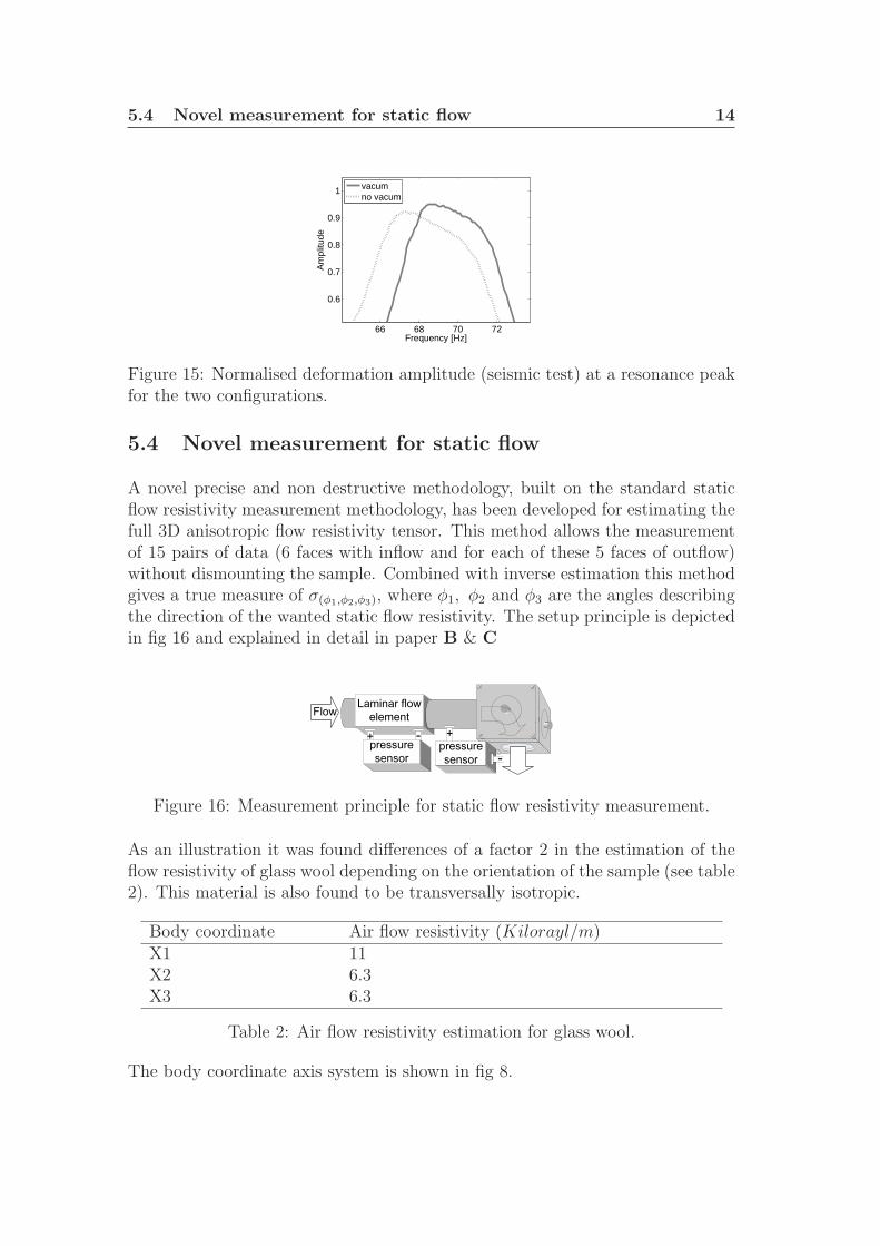
A novel precise and non destructive methodology, built on the standard staticflow resistivity measurement methodology, has been developed for estimating thefull 3D anisotropic flow resistivity tensor. This method allows the measurementof 15 pairs of data (6 faces with inflow and for each of these 5 faces of outflow)without dismounting the sample. Combined with inverse estimation this methodgives a true measure of σ(φ1,φ2,φ3), where φ1, φ2 and φ3 are the angles describingthe direction of the wanted static flow resistivity. The setup principle is depictedin fig 16 and explained in detail in paper B & C
Laminar flow element CFlow
pressure sensor
+
pressure sensor
+
Figure 16: Measurement principle for static flow resistivity measurement.
As an illustration it was found differences of a factor 2 in the estimation of theflow resistivity of glass wool depending on the orientation of the sample (see table2). This material is also found to be transversally isotropic.
Body coordinate Air flow resistivity (Kilorayl/m)X1 11X2 6.3X3 6.3
Table 2: Air flow resistivity estimation for glass wool.
The body coordinate axis system is shown in fig 8.
6 Inverse estimation 15
6 Inverse estimation
All the inverse estimation calculation are based on the method of moving asymp-totes (MMA) by Svanberg[13], it represents a family of convex approximationmethods suitable for optimization problems.
The function f0 is the objective function. The functions fi are the constraints.The implicit functions fi are approximated with the explicit functions fi(k). Thechoices of these approximating functions are based on the previously calculatedfunction values and gradients. Each approximation function fik(x) are obtainedby a linearisation of fi(x) in variables of the type 1/(Ue − xe) or 1/(xe − Le)where Le and Ue are parameters that satisfy Le ≤ xe(k) ≤ Ue (The valuesof the asymptotic points Le and Ue are changed between each iteration). Theasymptotic points Le and Ue are always given finite values. A heuristic way canthen be used to update the asymptotic points Le and Ue. The asymptotes movecloser to each other when we iterate to the optimal design. The main advantageof using MMA is that in MMA fi(x) is convex and then closer to the behaviourof the objective and constraint functions, furthermore it is robust and able tohandle almost all types of constraints and design variables.
To find the full material parameters, inverse estimation is performed using a finiteelement model of the setup, with proper boundary conditions, varying parametersused for the simulation until a satisfactory least square fit of the predicted fieldsas compared to the experimental data.
Standard measurement techniques usually allow for identification of the mate-rial properties in the body coordinate directions of a material. This is achievedthrough an extraction of samples and subsequent testing of these in unidirec-tional loading conditions. As the degree of anisotropy is as yet unknown, theinfluence of the anisotropic properties gives only limited information (i.e. in thebody coordinate directions of a material). On the contrary, the use of high qual-ity measurement combined with inverse estimation based on FEM result, allowfor identification of the material properties in all directions. Promising result arefound for the estimation of the flow resistivity tensor (paper B & C), and forthe determination of constitutive models for elasticity and dynamic behaviour inpolymer foams (paper D & E).
7 Conclusion and future Work 16
7 Conclusion and future Work
The principal relevant new notions of this thesis are:- To apply a coherent and integrated set of experimental and numerical methodsto characterize the anisotropic, fully-relaxed static and dynamic foam elasticproperties.- The validation of these materials models applied in numerical analysis methodsbased on viscoelastic principles for simulating the linear vibration response offlexible polyurethane foam materials.
The use of a non destructive testing methodology where the same sample can beuse for static, dynamic and flow resistivity measurement is a crucial step forwardin the parameter estimation and will lead to a better accuracy in the parameterestimation.
The ultimate objective of this study is to link,Foam chemistry - Foam processing - Foam cell micromechanics - Macro-
scopic static & dynamic properties - End application performance
together, and to move back and forth along this chain, using analysis. Sincethese relationships are not well established, current foam development for vibra-tion applications by necessity is iterative, and most probably not optimal. Thecurrent research is a step towards a design methodology for soft foam materialsalleviating this lack of proper design tools.
Eventually, because porous materials properties can widely vary depending onthe location in the foam block from which they were extracted, a next step ofthis research would be a statistical studies of sample of different location induceddensity due different extraction locations. The goal of these studies would beto get a better understanding of the variation of the influence of the intrinsicparameters of porous media and to develop a density mapping law that wouldhelp to reduce testing time.
8 Acknowledgements 17
8 Acknowledgements
This project is carried out within The Marcus Wallenberg Laboratory for Soundand Vibration Research at the department of Aeronautical and Vehicle Engineer-ing. The financial support of the European project InMar (Contract No.NMPZ-CT-2003-501084) & Friendcopter (Contract No.AIP3-CT-2003-502773) is grate-fully acknowledged.
The author is very gratefully to Prof. Peter Goransson for his constructive ideas,support and encouragement, as well as for his human behaviour.
I also want to express my appreciation to- Dr Kent Lindgren and Danilo Prevelic for there precious help and kindnessduring the time I passed performing experiment- Dr Nils-Erik Horlin for his help and knowledge- Brad Semeniuk for constructive discussions and active support in this research- Dr Gunnar Melin for his introduction to optical measurement- The Onera for supplying melamine foam sample and in particular Laurent Guil-laumie for sharing his knowledge about melamine.
The provision of the glass wool samples by EcophonR© and polyurethane byPhilips R© is acknowledged.
Merci a Karen et a MichaelMerci a Crispin, Karl et Martin
Merci a Metro BohemeMerci aux autres
REFERENCES 18
References
[1] J. F. Allard, R. Bourdier, and A. L’Esperance, “Anisotropic effect in glasswool on normal impedance in oblique incidence”, Journal of Sound and Vibra-tion 114, 233–238 (1987).
[2] L. Gibson and M. Ashby, Cellular Solids, Structure and properties. 2nd edition(Cambridge University Press) (1997).
[3] A. T. Huber and L. J. Gibson, “Anisotropy of foams”, Journal of MaterialsScience 23, Issue 8, 3031–30400 (1988).
[4] V. Tarnow, “Measured anisotropic air flow resistivity and sound attenuationof glass wool”, The Journal of the Acoustical Society of America 111, Issue
6, 2735–2739 (2002).
[5] J. Tran-Van, “Mechanical parameters measurement of transverse isotropicmineral wool”, in INCE Conference Proceedings, volume 208, Issue 1, 1089–1095 (2005).
[6] H. Rice and P. Goransson, “A dynamical model of light fibrous materials”,International Journal of Mechanical Sciences Volume 41, Number 4, 561–579 (1998).
[7] P. Goransson and P. Lemarinier, “Sound transmission through double panelsystems lined with soaked insulation materials”, in 4th AIAA/CEAS Aeroa-coustics conference, volume Paper no AIAA-98-2345 (1998).
[8] M. Melon, E. Mariez, C. Ayrault, & S. Sahraoui, Acoustical and mechanicalcharacterization of anisotropic open-cell foams, The Journal of the AcousticalSociety of America – November 1998 – Volume 104, Issue 5, pp. 2622-2627(1998)
[9] L.G. Melin, Optical whole field measurement techniques for mechanical test-ing, a review intern report for the Aeronautical Research Institute of Sweden,FFA, (1999)
[10] Aramis v5.4 User MAnual, GOM Mbh, www.gom.com (2005)
[11] Hernandez Jimenez, B. Vinagre Jara, J. Hernandez Santiago, Relaxationmodulus in the fitting of polycarbonate and poly(vinyl chloride) viscoelas-tic polymers by a fractional Maxwell model, Colloid Polym Sci 280:485-489,(2002).
[12] Y. C. Fung, Foundation of Solid Mechanics, Prentice-Hall, Englewood Cliffs,NJ, 1968

REFERENCES 19
[13] K. Svanberg, “Method of moving asymptotes a new method for structuraloptimization”, International Journal for Numerical Methods in Engineering24, 359–373 (1987).


![The power of ultrasonic characterisation for …...The main principles of ultrasonic evaluation have been given by Roux [1] for the elastic coefficients evaluation of homogeneous anisotropic](https://img.pdfslide.us/doc/110x75/5e90952d57e55806c209bde1/the-power-of-ultrasonic-characterisation-for-the-main-principles-of-ultrasonic.jpg)