Embed Size (px)
Citation preview
EL Mini TOP VIEW LED 65-11-C70200H-AM
Features
• Package:Cool White LED with PLCC 2 package
• Emitted Color:Cool White
• Typ. Luminance Intensity:2,000 mcd @ 20mA
• Typ. Luminous Flux:5 lm @ 20mA
• Viewing angle:120o
• ESD:up to 8KV
• MSL:2
• Preconditioning:According to JEDEC J-STD 020D Level 2
• Qualifications:According to AEC-Q101
• Compliance with RoHS and REACH
Applications
• Automotive Interior Lighting, Dashboard, Switch, Reading lamp, Audio, and Car Infortainment, etc.
• Backlight: LCD, switches, symbol, mobile phone and illuminated advertising.
• Optical indicator.
• General applications.
DATASHEET
65-11-C70200H-AM
2 Copyright © 2014, Everlight All Rights Reserved. Release Date: Sep.12.2016 Issue No: DSE-0017026 www.everlight.com
Contents Characteristics .............................................................................................................................. 3
Absolute Maximum Ratings ............................................................................................ 4
Characteristics Graph ........................................................................................................... 5
Binning Information ............................................................................................................... 10
Part Number ................................................................................................................................... 15
Ordering Information ............................................................................................................ 16
Mechanical Dimension ........................................................................................................ 17
Recommended Soldering Pad .................................................................................... 18
Reflow Soldering Profile ................................................................................................... 18
Packaging Information ........................................................................................................ 19
Precaution for Use................................................................................................................... 21

DATASHEET
65-11-C70200H-AM
3 Copyright © 2014, Everlight All Rights Reserved. Release Date: Sep.12.2016 Issue No: DSE-0017026 www.everlight.com
1. Characteristics
Parameter Symbol Min. Typ. Max. Unit Condition
Forward Current Cool White IF 2 20 30 mA ---
Luminous Intensity Cool White Iv 1400 2000 3550 mcd IF=20mA
Forward Voltage Cool White VF 2.75 3.1 3.75 V IF=20mA
Viewing Angle Cool White φ --- 120 --- deg IF=20mA
Color Cool White CIE x --- 0.3 --- --- IF=20mA
Color Cool White CIE y --- 0.3 --- --- IF=20mA
Thermal Resistance (Junction to Solder)
Real Rth JS real --- 120 --- K/W IF=20mA
Electrical Rth JS el --- 95 ---
Notes:
1. Luminous Intensity measurement tolerance: ±8%.
2. The data of Luminous Intensity measured at thermal pad=25°C.
3. Typical luminous Intensity or light output performance is operated within the condition guided by this datasheet.
4. Forward voltage measurement tolerance: ±0.1V.
5. The VF range shown in the table above indicates 99% output.
6. Tolerance of Chromaticity Coordinates x,y: ±0.005.
DATASHEET
65-11-C70200H-AM
4 Copyright © 2014, Everlight All Rights Reserved. Release Date: Sep.12.2016 Issue No: DSE-0017026 www.everlight.com
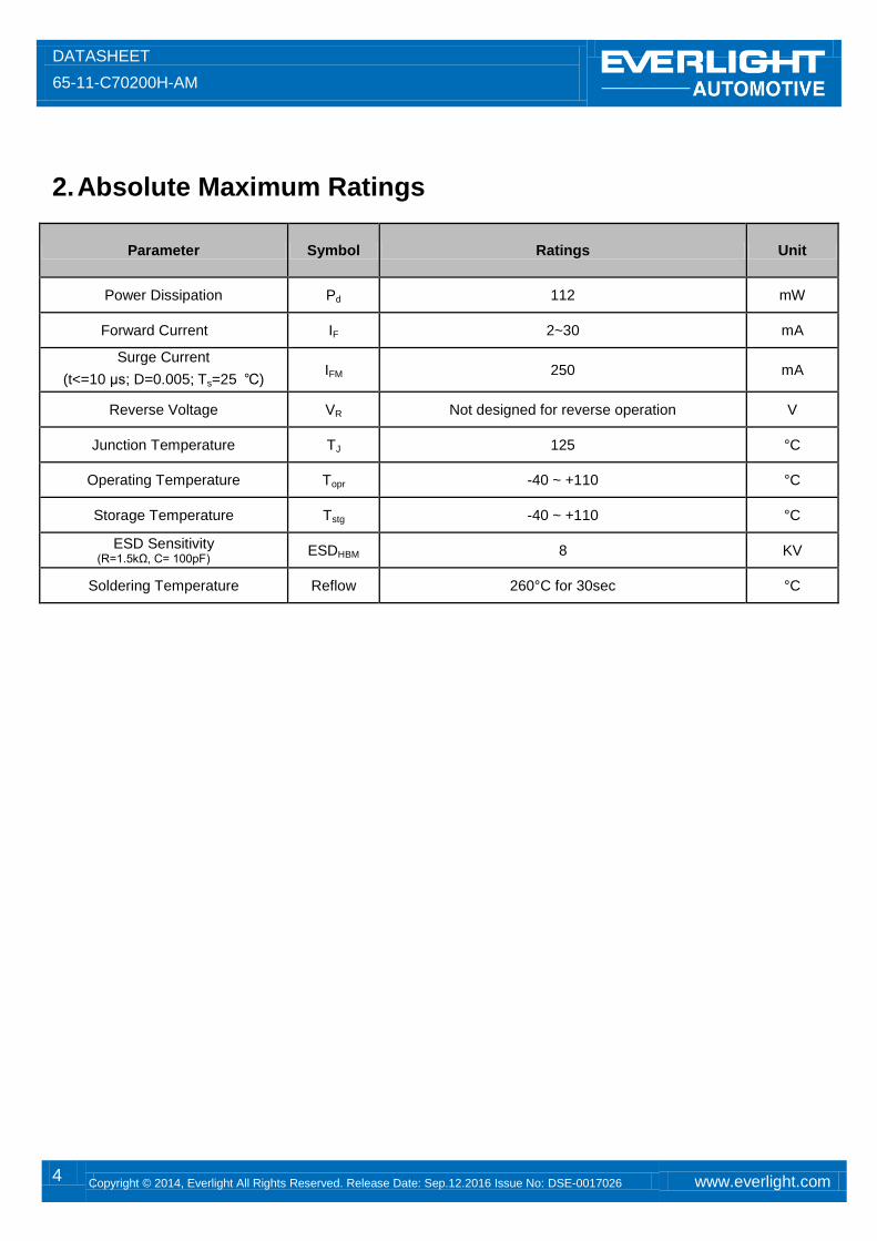
2. Absolute Maximum Ratings
Parameter Symbol Ratings Unit
Power Dissipation Pd 112 mW
Forward Current IF 2~30 mA
Surge Current
(t<=10 μs; D=0.005; Ts=25 ℃) IFM 250 mA
Reverse Voltage VR Not designed for reverse operation V
Junction Temperature TJ 125 °C
Operating Temperature Topr -40 ~ +110 °C
Storage Temperature Tstg -40 ~ +110 °C
ESD Sensitivity (R=1.5kΩ, C= 100pF)
ESDHBM 8 KV
Soldering Temperature Reflow 260°C for 30sec °C
DATASHEET
65-11-C70200H-AM
5 Copyright © 2014, Everlight All Rights Reserved. Release Date: Sep.12.2016 Issue No: DSE-0017026 www.everlight.com
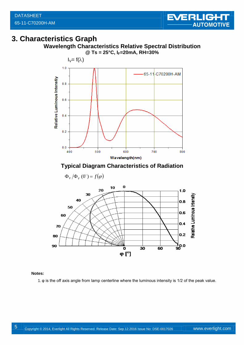
3. Characteristics Graph Wavelength Characteristics Relative Spectral Distribution
@ Ts = 25°C, IF=20mA, RH=30%
IV= f()
Typical Diagram Characteristics of Radiation
Notes:
1. φ is the off axis angle from lamp centerline where the luminous intensity is 1/2 of the peak value.
fVV )0(
DATASHEET
65-11-C70200H-AM
6 Copyright © 2014, Everlight All Rights Reserved. Release Date: Sep.12.2016 Issue No: DSE-0017026 www.everlight.com
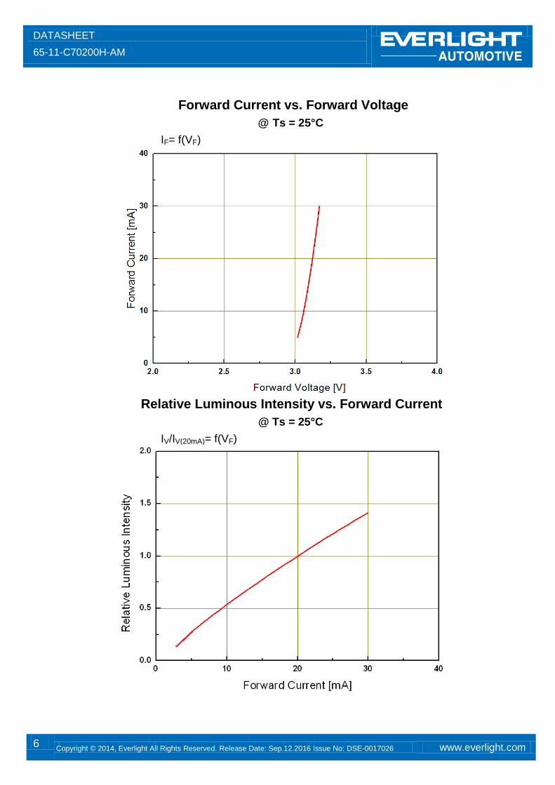
Forward Current vs. Forward Voltage
@ Ts = 25°C
IF= f(VF)
Relative Luminous Intensity vs. Forward Current
@ Ts = 25°C
IV/IV(20mA)= f(VF)
DATASHEET
65-11-C70200H-AM
7 Copyright © 2014, Everlight All Rights Reserved. Release Date: Sep.12.2016 Issue No: DSE-0017026 www.everlight.com
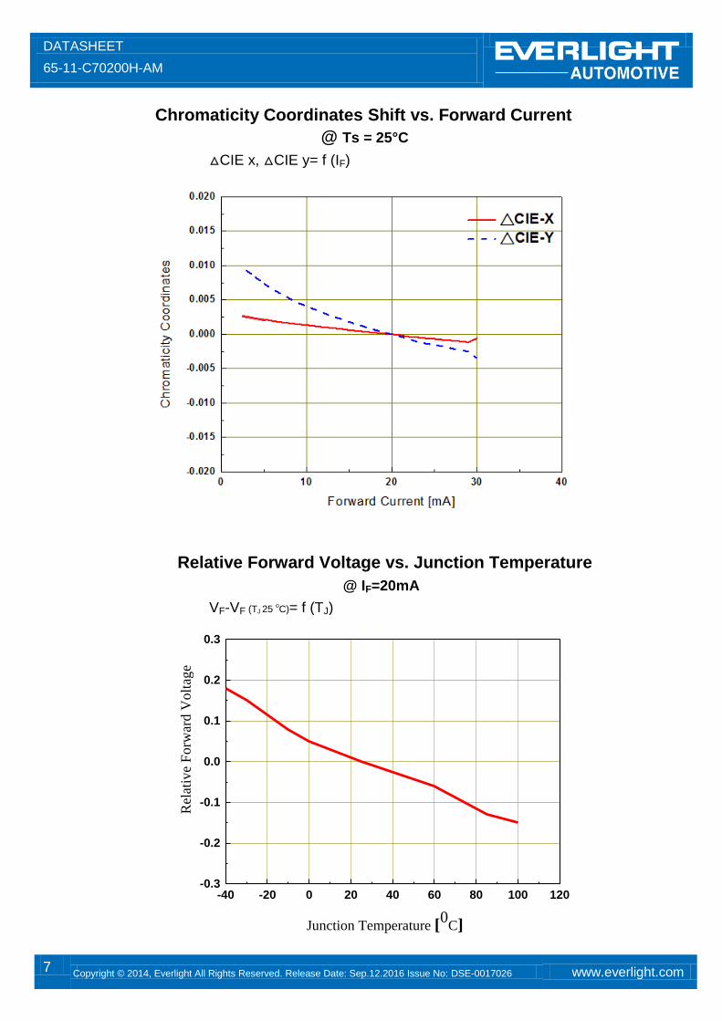
Chromaticity Coordinates Shift vs. Forward Current
@ Ts = 25°C
△CIE x, △CIE y= f (IF)
Relative Forward Voltage vs. Junction Temperature
@ IF=20mA
VF-VF (TJ 25 oC)= f (TJ)
-40 -20 0 20 40 60 80 100 120
-0.3
-0.2
-0.1
0.0
0.1
0.2
0.3
Rel
ativ
e F
orw
ard
Vo
ltag
e
Junction Temperature [0
C]

DATASHEET
65-11-C70200H-AM
8 Copyright © 2014, Everlight All Rights Reserved. Release Date: Sep.12.2016 Issue No: DSE-0017026 www.everlight.com
Relative Luminous Intensity vs. Junction Temperature
@ IF=20mA
IV/IV (TJ 25 oC)= f (TJ)
Chromaticity Coordinates Shift vs. Junction Temperature
@ IF=10mA
-40 -20 0 20 40 60 80 100 120 140-0.020
-0.015
-0.010
-0.005
0.000
0.005
0.010
0.015
0.020
Ch
rom
ati
cit
y C
oo
rdin
ate
s
Junction Temperature [oC]
△ CIE-X
△ CIE-Y
-40 -20 0 20 40 60 80 100 120 1400.2
0.4
0.6
0.8
1.0
1.2
1.4
1.6
R
ela
tiv
e L
um
ino
us
Inte
nsi
ty
Junction Temperature [oC]
DATASHEET
65-11-C70200H-AM
9 Copyright © 2014, Everlight All Rights Reserved. Release Date: Sep.12.2016 Issue No: DSE-0017026 www.everlight.com
10-5
10-4
10-3
10-2
10-1
100
101
102
0.00
0.05
0.10
0.15
0.20
0.25
0.30
D=
1
0.5
0.2
0.1
0.05
0.02
0.01
0.005
tp
IF A
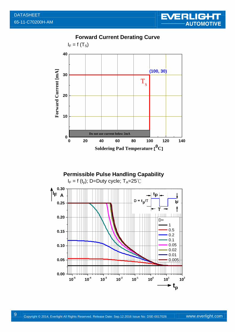
Forward Current Derating Curve
IF = f (TS)
Permissible Pulse Handling Capability
IF = f (tp); D=Duty cycle; TA=25℃
0 20 40 60 80 100 120 1400
10
20
30
40
TS
(100, 30)
Fo
rw
ard
Cu
rren
t [m
A]
Soldering Pad Temperature [0
C]
Do not use current below 2mA
DATASHEET
65-11-C70200H-AM
10 Copyright © 2014, Everlight All Rights Reserved. Release Date: Sep.12.2016 Issue No: DSE-0017026 www.everlight.com
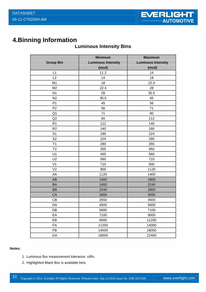
4.Binning Information
Luminous Intensity Bins
Group Bin
Minimum Maximum
Luminous Intensity Luminous Intensity
(mcd) (mcd)
L1 11.2 14
L2 14 18
M1 18 22.4
M2 22.4 28
N1 28 35.5
N2 35.5 45
P1 45 56
P2 56 71
Q1 71 90
Q2 90 112
R1 112 140
R2 140 180
S1 180 224
S2 224 280
T1 280 355
T2 355 450
U1 450 560
U2 560 710
V1 710 900
V2 900 1120
AA 1120 1400
AB 1400 1800
BA 1800 2240
BB 2240 2800
CA 2800 3550
CB 3550 4500
DA 4500 5600
DB 5600 7100
EA 7100 9000
EB 9000 11200
FA 11200 14000
FB 14000 18000
GA 18000 22400
Notes:
1. Luminous flux measurement tolerance: ±8%.
2. Highlighted Black Box is available bins.
DATASHEET
65-11-C70200H-AM
11 Copyright © 2014, Everlight All Rights Reserved. Release Date: Sep.12.2016 Issue No: DSE-0017026 www.everlight.com
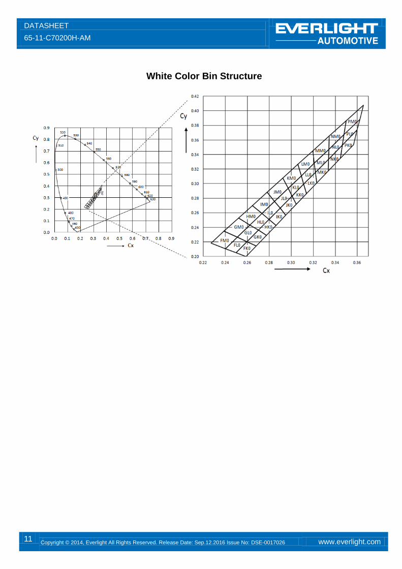
White Color Bin Structure
DATASHEET
65-11-C70200H-AM
12 Copyright © 2014, Everlight All Rights Reserved. Release Date: Sep.12.2016 Issue No: DSE-0017026 www.everlight.com
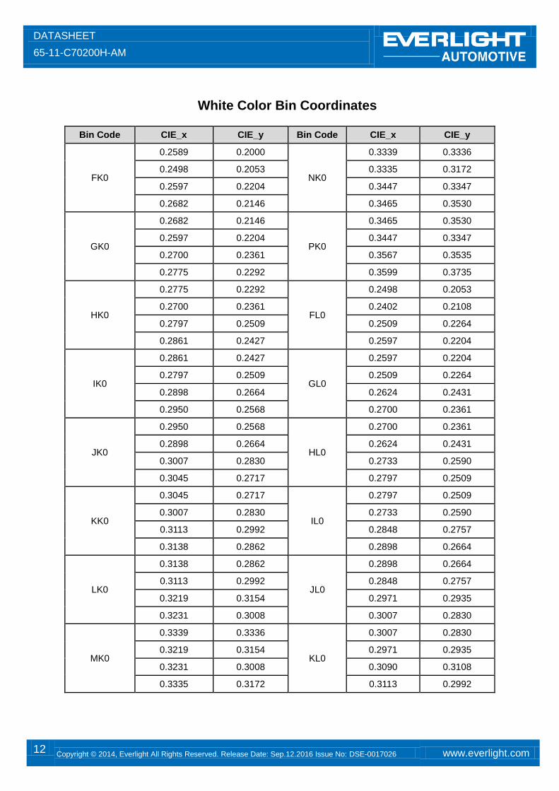
White Color Bin Coordinates
Bin Code CIE_x CIE_y Bin Code CIE_x CIE_y
FK0
0.2589 0.2000
NK0
0.3339 0.3336
0.2498 0.2053 0.3335 0.3172
0.2597 0.2204 0.3447 0.3347
0.2682 0.2146 0.3465 0.3530
GK0
0.2682 0.2146
PK0
0.3465 0.3530
0.2597 0.2204 0.3447 0.3347
0.2700 0.2361 0.3567 0.3535
0.2775 0.2292 0.3599 0.3735
HK0
0.2775 0.2292
FL0
0.2498 0.2053
0.2700 0.2361 0.2402 0.2108
0.2797 0.2509 0.2509 0.2264
0.2861 0.2427 0.2597 0.2204
IK0
0.2861 0.2427
GL0
0.2597 0.2204
0.2797 0.2509 0.2509 0.2264
0.2898 0.2664 0.2624 0.2431
0.2950 0.2568 0.2700 0.2361
JK0
0.2950 0.2568
HL0
0.2700 0.2361
0.2898 0.2664 0.2624 0.2431
0.3007 0.2830 0.2733 0.2590
0.3045 0.2717 0.2797 0.2509
KK0
0.3045 0.2717
IL0
0.2797 0.2509
0.3007 0.2830 0.2733 0.2590
0.3113 0.2992 0.2848 0.2757
0.3138 0.2862 0.2898 0.2664
LK0
0.3138 0.2862
JL0
0.2898 0.2664
0.3113 0.2992 0.2848 0.2757
0.3219 0.3154 0.2971 0.2935
0.3231 0.3008 0.3007 0.2830
MK0
0.3339 0.3336
KL0
0.3007 0.2830
0.3219 0.3154 0.2971 0.2935
0.3231 0.3008 0.3090 0.3108
0.3335 0.3172 0.3113 0.2992
DATASHEET
65-11-C70200H-AM
13 Copyright © 2014, Everlight All Rights Reserved. Release Date: Sep.12.2016 Issue No: DSE-0017026 www.everlight.com
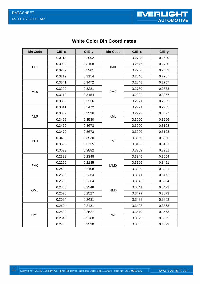
White Color Bin Coordinates
Bin Code CIE_x CIE_y Bin Code CIE_x CIE_y
LL0
0.3113 0.2992
IM0
0.2733 0.2590
0.3090 0.3108 0.2646 0.2700
0.3209 0.3281 0.2780 0.2883
0.3219 0.3154 0.2848 0.2757
ML0
0.3341 0.3472
JM0
0.2848 0.2757
0.3209 0.3281 0.2780 0.2883
0.3219 0.3154 0.2922 0.3077
0.3339 0.3336 0.2971 0.2935
NL0
0.3341 0.3472
KM0
0.2971 0.2935
0.3339 0.3336 0.2922 0.3077
0.3465 0.3530 0.3060 0.3266
0.3479 0.3673 0.3090 0.3108
PL0
0.3479 0.3673
LM0
0.3090 0.3108
0.3465 0.3530 0.3060 0.3266
0.3599 0.3735 0.3196 0.3451
0.3623 0.3882 0.3209 0.3281
FM0
0.2388 0.2348
MM0
0.3345 0.3654
0.2269 0.2185 0.3196 0.3451
0.2402 0.2108 0.3209 0.3281
0.2509 0.2264 0.3341 0.3472
GM0
0.2509 0.2264
NM0
0.3345 0.3654
0.2388 0.2348 0.3341 0.3472
0.2520 0.2527 0.3479 0.3673
0.2624 0.2431 0.3498 0.3863
HM0
0.2624 0.2431
PM0
0.3498 0.3863
0.2520 0.2527 0.3479 0.3673
0.2646 0.2700 0.3623 0.3882
0.2733 0.2590 0.3655 0.4079
DATASHEET
65-11-C70200H-AM
14 Copyright © 2014, Everlight All Rights Reserved. Release Date: Sep.12.2016 Issue No: DSE-0017026 www.everlight.com
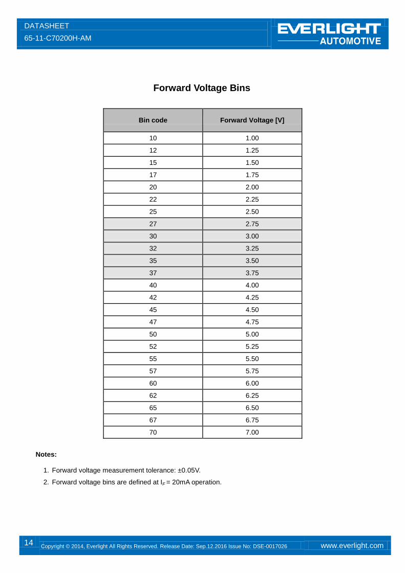
Forward Voltage Bins
Bin code Forward Voltage [V]
10 1.00
12 1.25
15 1.50
17 1.75
20 2.00
22 2.25
25 2.50
27 2.75
30 3.00
32 3.25
35 3.50
37 3.75
40 4.00
42 4.25
45 4.50
47 4.75
50 5.00
52 5.25
55 5.50
57 5.75
60 6.00
62 6.25
65 6.50
67 6.75
70 7.00
Notes:
1. Forward voltage measurement tolerance: ±0.05V.
2. Forward voltage bins are defined at IF = 20mA operation.
DATASHEET
65-11-C70200H-AM
15 Copyright © 2014, Everlight All Rights Reserved. Release Date: Sep.12.2016 Issue No: DSE-0017026 www.everlight.com
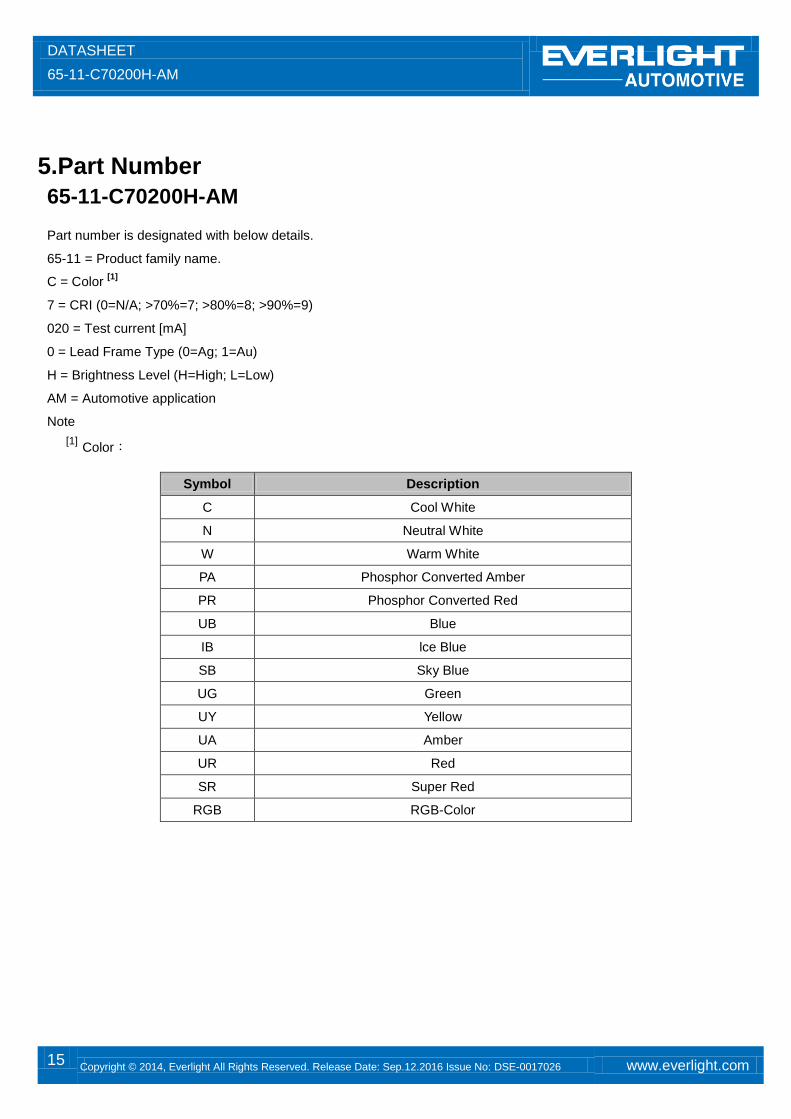
5.Part Number
65-11-C70200H-AM
Part number is designated with below details.
65-11 = Product family name.
C = Color [1]
7 = CRI (0=N/A; >70%=7; >80%=8; >90%=9)
020 = Test current [mA]
0 = Lead Frame Type (0=Ag; 1=Au)
H = Brightness Level (H=High; L=Low)
AM = Automotive application
Note
[1] Color:
Symbol Description
C Cool White
N Neutral White
W Warm White
PA Phosphor Converted Amber
PR Phosphor Converted Red
UB Blue
IB lce Blue
SB Sky Blue
UG Green
UY Yellow
UA Amber
UR Red
SR Super Red
RGB RGB-Color
DATASHEET
65-11-C70200H-AM
16 Copyright © 2014, Everlight All Rights Reserved. Release Date: Sep.12.2016 Issue No: DSE-0017026 www.everlight.com
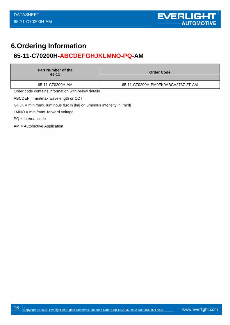
6.Ordering Information
65-11-C70200H-ABCDEFGHJKLMNO-PQ-AM
Part Number of the 65-11
Order Code
65-11-C70200H-AM 65-11-C70200H-PM0FK0ABCA2737-2T-AM
Order code contains information with below details:
ABCDEF = min/max wavelength or CCT
GHJK = min./max. luminous flux in [lm] or luminous intensity in [mcd]
LMNO = min./max. forward voltage
PQ = internal code
AM = Automotive Application
DATASHEET
65-11-C70200H-AM
17 Copyright © 2014, Everlight All Rights Reserved. Release Date: Sep.12.2016 Issue No: DSE-0017026 www.everlight.com
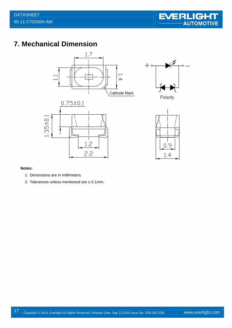
7. Mechanical Dimension
Notes:
1. Dimensions are in millimeters.
2. Tolerances unless mentioned are ± 0.1mm.
DATASHEET
65-11-C70200H-AM
18 Copyright © 2014, Everlight All Rights Reserved. Release Date: Sep.12.2016 Issue No: DSE-0017026 www.everlight.com
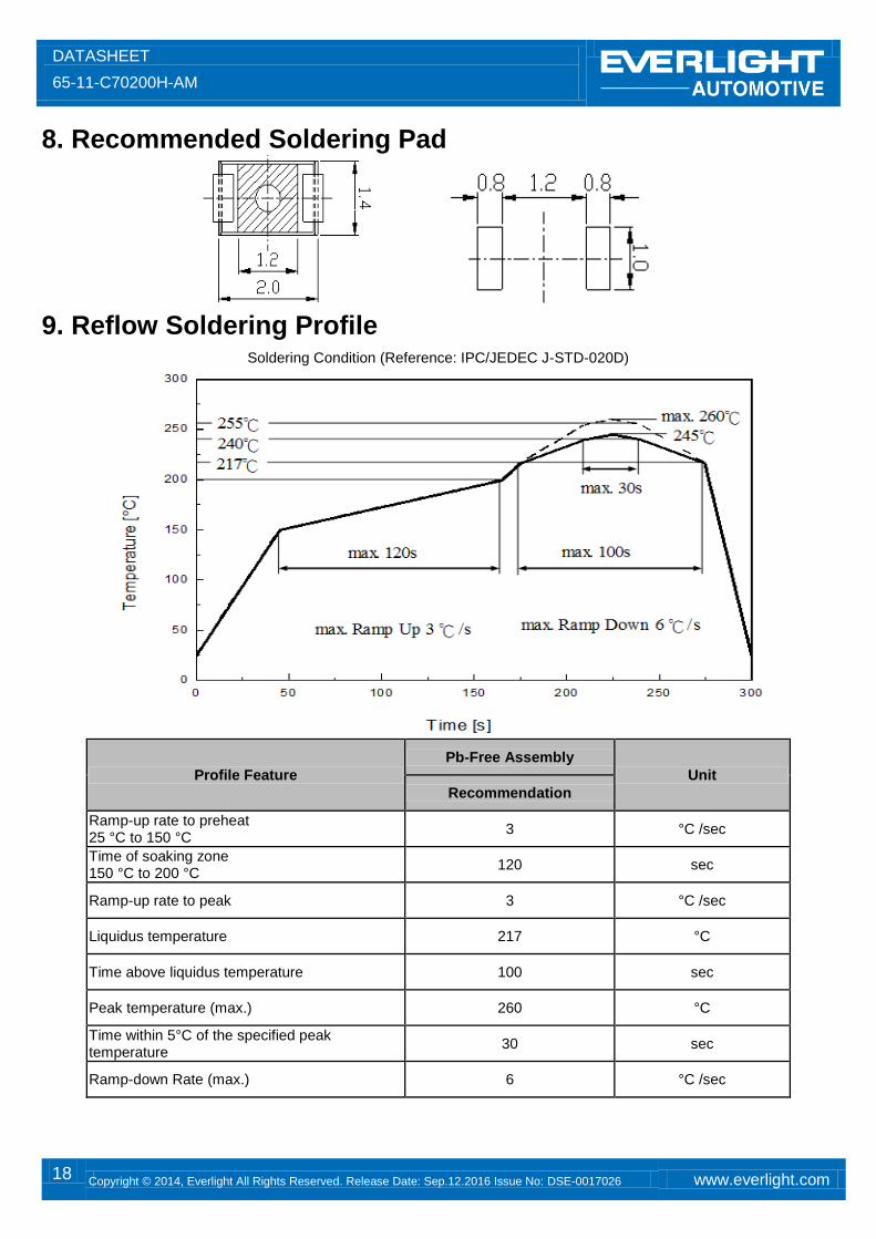
8. Recommended Soldering Pad
9. Reflow Soldering Profile
Soldering Condition (Reference: IPC/JEDEC J-STD-020D)
Profile Feature
Pb-Free Assembly
Unit
Recommendation
Ramp-up rate to preheat 25 °C to 150 °C
3 °C /sec
Time of soaking zone 150 °C to 200 °C
120 sec
Ramp-up rate to peak 3 °C /sec
Liquidus temperature 217 °C
Time above liquidus temperature 100 sec
Peak temperature (max.) 260 °C
Time within 5°C of the specified peak temperature
30 sec
Ramp-down Rate (max.) 6 °C /sec
DATASHEET
65-11-C70200H-AM
19 Copyright © 2014, Everlight All Rights Reserved. Release Date: Sep.12.2016 Issue No: DSE-0017026 www.everlight.com
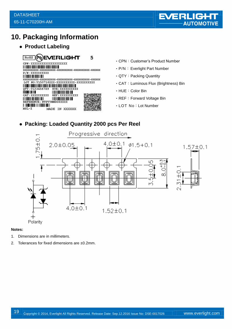
10. Packaging Information
Product Labeling
‧CPN:Customer’s Product Number
‧P/N:Everlight Part Number
‧QTY:Packing Quantity
‧CAT:Luminous Flux (Brightness) Bin
‧HUE:Color Bin
‧REF:Forward Voltage Bin
‧LOT No:Lot Number
Packing: Loaded Quantity 2000 pcs Per Reel
Notes:
1. Dimensions are in millimeters.
2. Tolerances for fixed dimensions are ±0.2mm.
DATASHEET
65-11-C70200H-AM
20 Copyright © 2014, Everlight All Rights Reserved. Release Date: Sep.12.2016 Issue No: DSE-0017026 www.everlight.com
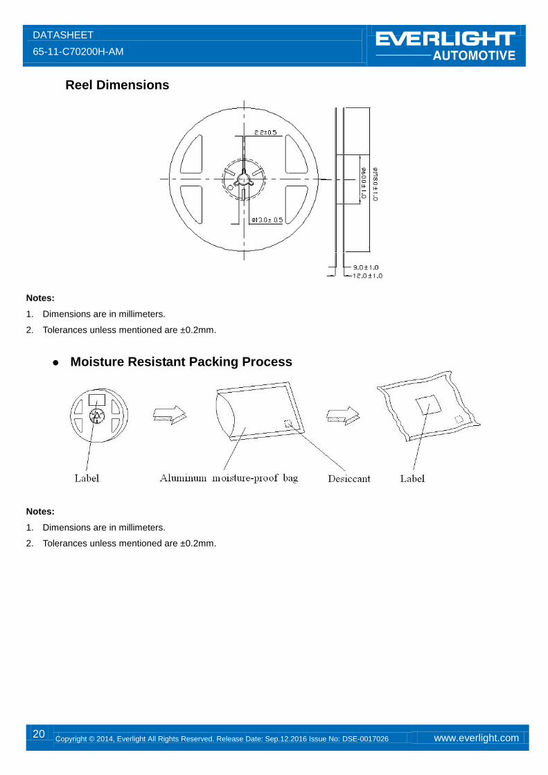
Reel Dimensions
Notes:
1. Dimensions are in millimeters.
2. Tolerances unless mentioned are ±0.2mm.
Moisture Resistant Packing Process
Notes:
1. Dimensions are in millimeters.
2. Tolerances unless mentioned are ±0.2mm.

DATASHEET
65-11-C70200H-AM
21 Copyright © 2014, Everlight All Rights Reserved. Release Date: Sep.12.2016 Issue No: DSE-0017026 www.everlight.com
11. Precaution for Use 1. Over-current-proof
Customer must apply resistors for protection; otherwise slight voltage shift will cause big current change (burn out will happen).
2. Assemblies Do not stack assemblies containing LEDs to prevent damage to the optical surface of LEDs. Forces applied to the
optical surface may result in the surface being damaged.
3. Soldering Condition 3.1 When soldering, do not put stress on the LEDs during heating. 3.2 After soldering, do not warp the circuit board.
4. Soldering Iron
Each terminal is to go to the tip of soldering iron temperature less than 350℃ for 3 seconds within once in less
than the soldering iron capacity 25W. Leave two seconds and more intervals, and do soldering of each terminal. Be careful because the damage of the product is often started at the time of the hand solder.
5. Repairing Repair should not be done after the LEDs have been soldered. When repairing is unavoidable, a double-head soldering iron should be used (as below figure). It should be confirmed beforehand whether the characteristics of the LEDs will or will not be damaged by repairing.
DATASHEET
65-11-C70200H-AM
22 Copyright © 2014, Everlight All Rights Reserved. Release Date: Sep.12.2016 Issue No: DSE-0017026 www.everlight.com
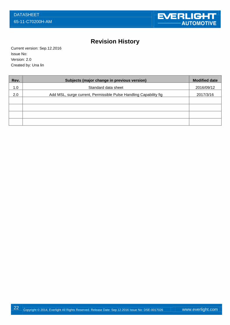
Revision History
Current version: Sep.12.2016
Issue No:
Version: 2.0
Created by: Una lin
Rev. Subjects (major change in previous version) Modified date
1.0 Standard data sheet 2016/09/12
2.0 Add MSL, surge current, Permissible Pulse Handling Capability fig 2017/3/16