Embed Size (px)
Citation preview

NRL Memorandumt Repirt 4734
-Electromagnetic Pulse (EMP) Handbook DevelopmentSA for the Defense Nuclear Agency (DNA)
Annual Report for thePeriod October 1, 1980 - September 30, 1981
S~ J. M. PIERRE
Plasma .Radketion GroupPlasma Physics Division
EL.ECTEWSFEB 2 5 10 3
February 22, 1982 EB
This research was sponsored by the Defense Nuclear Agency under Subtask099QAi_9E•work unit 00001 and work unit title "Handbook Integration.'
.8a
NAVAL RESEAKCH LAISORATORYWashingtou, D.C.
Approved (or public rmIuse; diutribution unlimitel,
8 2 25 069

SECURITY CLASSIFICATION OF TmIS PAGE (When Data Emote~d)
READ INSTRUCTIONSREPORT DOCUMENTATION PAGE BEFORE COMPLETING FORM
1. REPORT NUMBER ;2. GOVT ACCESSION NO. S. RECIPIENT'S CATALOG NUMBER
NRL Memorandum Report 4734 11);I/Z / 594. TITLE (and S.6btitI.) TYPE OF REPORT It PERIOD COVEREDo
*ELECTROMAGNETIC PULSE (EMP) HANDBOOK Annual report for the period*DEVELOPMENT FOR THE DEFENSE NUCLEAR Oct. 1, 1980 - Sept. 30, 1981
AGENCY (DNA) Annual Repoit for the Period6.EROFIGR.RERTNMAOctober 1, 1980 - September 30, 1981 6. PERFOP_________REPORT______
7. AUTNOR(s) D. CONTRACT OR GRANT NUM@LER(&)
J.M. Pierre J
S. PERFORMING ORGANIZATION NAME AND ADDRESS 10. PROGRAM ELFMENT. PROJECT, TASKAREA A WORK UNIT NUMUERS
Naval Reaearch Laboratory6215;40931Washington, DC 20375
It. CONTROLLING OFFICE NAME AND ADDRESS 12. REPORT DATE
Defense Nuclear Agency February 22, 1982Washington, DC 20305 13. NUMBER OF PAGES
___________________________107
1.MONITORING AGENCY NAME A AOORESS(Il different froa, Congrollinit Office) IS. SECURITY CLASS. (of this repotl)UNCLASSIFIED
ISa. DECL ASSI FIC ATI ON/ DOWN GRADIN r
SCNEDUL.E
IA. DISTRIBUTION STATEMENT (of this Report)I Approved for public release; distribution unlimited.
17. DISTRIBUTION STATEMENT (of the cabsrated ntered In Block 20. If different froam Report)
I: IS. SUPPLEMENTARY NOTES
This research was sponsored by the Defense Nuclear Agency under Subtask O99QAXCE,work unit 00001 and work unit title "Handbook Integration."
IS. KEY WORDS (Continue on reverse side It necessary and identity by block itimib.,)
Electromagnetic pulse (EMP)HardeningFacility protectionHandbook development
0.ABSTRACT (Continhue on reverse aide If necaeesm and Identify by black memnber)
%uring FY 81, the Defense Nuclear Agency (DNA) initiated a program with the Naval'Research Laboratory to provide technical and management support in the developmentof an electromagnetic pulse (EMP) handbook for ground, based facilities. The focus of thehandbook program during the first year was on the assessment of the data needs of the
j EMP user community and the adequacy of the existing data base. This report provides asummary of the activities, findings, and accomplishments during the past year in theEMP handbook development area.
DD , ,1473 EDITION OF I NOV 65 IS OýBSOLETE
S/N 0102,014- 6601SECURITY CLASSIFICATION OF TNIS PACE (Ufiem Does Eateed)
4 j

- I
CONTENTS
1. INTRODUCTION ...........................................
II. HANDBOOK DEVELOPMENT BACKGROUND .................. .2
III. HANDBOOK COMMITTEE COMPOSITION AND FUNCTION ........ 3
IV. COMMITTEE RECOMMENDATIONS AND ACTIONS .............. 4
V. HANDBOOK PHILOSOPHY .................................. 7
VI. THE HANDBOOK - A D YNAMIC DOCUMENT .................. 8
VII. SUMMARY ................................................ 8
ACKNOWLEDGMENT .......................................... 11
Appendix i -Distribution List for Progress Letters .................... 12
Appendix ii - Handbook Development Committee - FY 81 Members ...... 14
Appendix A -- Draft Executive Summary ............................ 15
Appendix B - Draft Outline for Volume I (Managers) .................. 46
Appendix C - Draft Outline for Volume II (Engineers/Designers) .......... 56
Appendix D - Draft Outline for Volume III(Operations and Maintenance Personnel) ................ 87
Acoession ForNTIS GRA&I
DT10 TABJU U7-imocut iceJtr-ti~fication
S.,> D~i ,tribution/Availability Codes
jAvnil and/or
Dist Special
iiii

ELECTROMAGNETIC PULSE (EMP) HANDBOOK DEVELOPMENT* I FOR THE DEFENSE NUCLEAR AGENCY (DNA)
Annual Report for the PeriodOctober 1, 1980 - September 30, 1981
1. INTRODUCTION
Elec-tromagnetic pulse (EMP) technology has evolved over the past
twenty years in response to the need to provide EMP protection - o'r
hardening - to materials, devices, equipment, or systems as specificI.needs arose. Although methodologies and procedures have been developedto meet the nuclear survivability requirements of particular systems,
relatively little effort has been directed toward the unification of what
has been learned concerning the effectiveness of various approaches; to
achieving an acceptable degree of nuclear hardness. This is particular!-,
true in the case of providing protection to ground based facilities
against nuclear induced EMP. Even though "hardened" facilities have been
built i.n the past, for example, those associated with the Safeguard
system, there is no clear understanding of how to plan, design,
construct, test, and maintain a hardened site.
With the increased complexity and sophistication of current and
proposed defense systems, particularly communication networks and missile
systems, and the many types of ground facilities which are required to
[ support such systems, there exists a continuing critical need to find
cost effective, efficient, and workable approaches to facility
hardening. Recognizing this need and the necessity for improving the
organization of the existing data base, the Defense Nuclear Agency
initiated a program during FY 81 to identify the needs of the EMP
community in terms of what data is required by various segments of the
federal, the defense, and the private sectors which would enable them to
make sound decisions which pertain to the hardening of ground based
facilities. While there does exist a large amount of experience and data
on the hardening of facilities, this expertise and data are not readily14 available in a form which is of practical use to any except those who are
H already well versed in the technologj. T"he existing body of knowledge
is, at present, spread out amongst numerous data sources. The DNA EMP
Handbook Development Program is an attempt to f ind a means of collecting
and making available the appropriate, state-of-the-art data on nuclearhardness to various levels of personnel involved in EMP protection.
Manuscript submitted November 23, 1981.

•.I
During FY 81, the Naval Research Laboratory (NRL) has provided
technical and management support to the Defense Nuclear AgenCy (DNA) in
the development of an EMP handbook for ground based facilities. This
"report provides a summary of the activities, findings, and
accomplishments during the past year in the handbook development area.
Seccion II presents the background conditions under which the handbook
development program was initiated. In Section III the rationale for the
formation of a handbook development committee is discussed. The
recommendations and the actions of this committee during the past year
are summarized in Section IV. Section V gives a statement of the generalphilosophy behind the handbook program, while Section VI touches briefly
upon the long term maintenance aspects of the data base. The highlights
of the handbook development program during FY 81 are synopsized in
Section VII.
A number of appendices are included in this report for the purpose
of documentation. Of particular note are the Executive Summary (Appendix
A) and the detailed outlines for each of the proposed volumes of the
handbook as it is presently envisioned (Appendices B-D).
II. HANDBOOK DEVELOPMENT BACKGROUND IIn October of 1980, a meeting sponsored by DNA/RAEE was held in
conjunction with the DNA EMP Simulation and Hardening Symposium at the
Naval Post Graduate School in Monterey, California. This meeting served
as an excellent opportunity to bring together experts from a large cross
section of the EMP community to discuss the need for an applications
oriented EMP handbook for ground based facilities. The general concensus
of both government and industrial representatives who attended the
meeting may be summarized as follows:
1. Although EMP technology is far from complete, it is
sufficiently mature to -meet many of the facilities EMP
protection requirements which exist today.
2. A critical need exists in both government and industry to have
access to the best available data on the plan, design,
verification, and maintenarce of an EMP hardened facility.
L -2-
'4!

3. Experience gained from the development of si-e protection for
ABM, Ainutemari, Defense Support Program, and NATO Wing Commandj
Posts, as well as improved and new Sata from current and
planned DNA experiments (eg. the Life Cycle Cost and the
Verification Protocol programs), should be unified and
organized Into handbook form.
From the inception of the program, a concerted effort has been Made
to encourage communication between the E1MW community, especially between
potential handbook contributors and users, in order to maximize the
effectiveness of the handbook to meet the community needs. Thus, a
survey of the participants in the Informal October meeting was conducted
Fto solicit ideas on a) the need f or a handbook, b) approaches to
handbook development, c) potential data sources/voids, and d) topics
appropriate for inclusion in the handbook. Many of the suggestions
concerning handbook content and organization, which were obtained in
response to the survey, have been Incorporated into the preliminary draft
outlines for the handbook, which will be discussed in Section IV. Copies
of the draft outlines generated by the committee have been circulated to
Vinterested government organizations for comment. In add:tion to the
survey, periodic progress letters on the handbook development program and
on committee activities have been sent to organizations who have
indicated active interest in EMP protection and in the handbook effort.
The distribution list for progress letters is given in.Appeadix i.
(Anyone who wishes to be included on the distribution list should contactI the author.)
IiIII. HANDBOOK COMMITTEE COMPOSITION AND FUNCTIONBecause the focus of the handbook program during the first year was
on the assessment of the community needs and the adequacy ot the existing
data base, it was highly desirable to establish a fornaat which allowed
for broad based community participation. Thus, a committee approach to
handbook development was adopted. A particularly att'.actIve feature of
the committee format was that it allowed for the direct involvement of

persons whose corporate backgrounds cover a wide spectrum of past and
preserat EMPv protection experience. This approach had the added advantage
that the data base assessment would be conducted by persons who had ready
access to and applications experience with the existing data.
A nine member Handbook Development Committee was formed in November,
1980. The members served on a voluntary basis and were charged with
providing technical guidance on data assessment. They acted as a peer
review group which examined the existing data base on the hardening of
facilities to determine where the data resides, the integrity. of the
data, and whether the data is in a form suitable for inclusion intoa
handbook. The approach which has been adopted toward handbook
development, as well as its proposed content and format, have evolved as
a result of committee recommendations made during the past year. It is
p lanned that approximately one third of the committee members will be
rotated each year so that community participation may be further
broadened as the program matures. The membership of the committee during
the past year is shown in Appendix ii.
IV. COMM4ITTEERECOMMENDATIONS AND ACTIONS
The handbook committee met formally on three occasions during FY
81. The schedule- of these meetings and the major milestones reached are
given in the following chart.
MEETINGS OF THE HANDBOOK DEVELOPME~NT COMMITTEE -FY 81
DATE(s) HOST MILESTONE(s)
December 12, 1980 Naval Research Laboratory Basic structure ofWashington, D.C. handbook identified.
Ll Subcommittees formed foreach handbook volume.
March 24-25,1981 Mission Research Corporation Draft outlines forHAlbuquerque, New Mexico volumes reviewed.
July 16-17, 1981 SRI International Draft executive summaryMenlo Park, California reviewed.
ml Draft outlines forvolumes finalized.
4

During the initial meeting at NRL, the committee concentrated onthree major issues. These were, first, the identification of the
objective of the handbook program, second, the definition of the
technical scope of the handbook, and third, the identification of the
audience to which the handbook is directed. The committee consensus on
each of these issues and the supporting rationale for come of the
decisions regarding these issues are summarized as follows.
1. Objective The basic objective of the handbook program is to
identify, collect, and maintain the best available EMP protection data on
ground based facilities and to transfer the requisite technology to
variouc levels of personnel who have EMP protection responsibility.
This objective is dictated by the urgent need within the military
services, government agencies, and industry to underst-and which hardness
options may be exercised now to minimize mistakes which will prove costly
to rectify in the future. In many instances, this need is time critical
because hardness implementation has become a commonplace requirement in
many military systems. In addition, while the need for EMP protection
expertise is increasing, the number of available EMP experts is
insufficient to meet the demand on a timely basis. Consequently, data
and issues which can be clearly identified should be cast into handbook
form to facilitate the technology transfer between the technologydevelopers and the user community.
2. Scope The committee recognized that not all EMP issues which
pertain to ground facilities can be adequately addressed by any single
handbook. It therefore elected to restrict the scope of the technical
content so that a reasonably usable document could be written and made
available to users within three years time. Thus, the pzraary emphasis
of the handbook is on the EMP protection of new facilities as opposed to
the retrofit of existing ones. However, much of the information in the
handbook will be equally applical1e to retrofit situations as well.
Similarly, it is intended to be applicable to ground facilities in
general, although it is expected that the handbook will be particularly
useful in the communications, command, and control (C3 ) area because much
of the recent EM? data base and interest is focused on C3 systems.
5

It was also decided that only high altitude EUP would be
addressed. Source re&ion EMP was deliberately not included at this time
because the issues are complex and the technology is not sufficiently
mature. In addition, the handbook is intended to be applications rather
than environment and phenomenology oriented. The long range Dlan for the
development and maintenance of the hanlbook does, however, allow for the
potential expansion of the technical scope to include other forms of EMP
in the future. The long range plan for the handbook will be discussed
later in Section VI.
3. Audience It is generally recognized within the EMP community
that EMP protection of any system is a life cycle consideration. As
such, it is important to consider EMP protection as part of other
protection requirements. The life cycle requirements of a facility are
specified in the planning phase of a system and must be carried out
through the design, construction, and maintenance phases. Three distinct
levels of personnel have been identified who have different types of EMP
protection responsibility at various stages of fa( ility development and
evolution. The first gorup consists of persons who have the task of
formulating and executing programs which are to result in a hardened
facility, namely, program managers. The second group is comprised of
engineers and designers who specify and construct the facility. The last
group includes the personnel who are responsible for the day-to-day
operation and maintenance of the facility. Each group must understand
the EHP problem in a different context and each has dlfferent data
requirements. In order to meet the needs of each group, the DNA EMP
Engineering Handbook for Ground Based Facilities has been organized into
three volumes. Each volume is directed to a different audience--Volume I
for the program manager, Volume II for the engineer/designer, and Volume
III for the operations and maintenance personnel.
As Appendix iishows, subcommittees of three members each were formedto lead each of the volumes. In the months that followed, the
subcommittees conducted interviews, assembled data, and developed
preliminary outlines for the three volumes. These outlines were reviewed
by the full committee at the March meeting which was held at Mission
6
-i

* Research Corporation in Albuquerque, New Mexico. During the following
quarter, changes and revisions of the outlines were made and a draft
executive summary for the handbook was developed. These were presented
* to the full committee for review during the July meeting which was hosted
by SRI International, Menlo Park, California. It should also be noted
that the handbook program and the volume outlines were reviewed by3DNA/DDST during the C Technical Review in June of 1981. The draft
versions of the executive summary and the outlines for each volume are
included in this report as Appendices A, B, C, and D respectively.
V. HANDBOOK PHILOSOPHY
The underlying philosophy behind the handbook development program is
that even though there does not presently nor will there ever exist a
universally applicable panacea for the EMP problem, the technology on
facilities hardening is sufficiently advanced to provide limited, and in
some cases adequate, salvation from the dilemma. To a large extent, the
growth in EMP awareness over the past twenty years can be directly
attiibutable to the "missionary" activities of DNA and its support
contractors since the FISHBOWL experiments in the early 1960s. There is
now widespread awareness of the existence and acceptance of the potential
acuteness of the EMP threat. It is encumbent upon the EMP community to
identify the critic~l technical EMP issues, to present in a usable form
the quality data obtained through its research and technology programs,
and to provide the user community with an understanding of the various
protection options which are available. The handbook is not a
1"cookbook" with recipes for the production of hardened facilities, but
rather will offer aids and cholces which will allow the user to decide
k which options are most appropriate for his particular requirements.
Particular attention will be given to providing the user of the handbook
with a clear understanding of the limitations and caveats which apply to
thc data.
7
I
VI. THE HANDBOOK - A DYNAMIC DOCUMENT
Since the understanding of EMP protecLln is likely co change with
time as the technology advances, it has been suggsted tnat the handbook
be maintained as a computerized data base. This concept will be
discussed in a separate report.
At present, it is envisioned that the handbook will be a dynamic
compendium of EMP protection methods, techniques and data which will
provide an accurate and timely, applications oriented view of available
EMP protection options. As the technology itself matures, changes,
updates, and revisions of the handbook will be required. In some
instances, it is expected that the handbook will point to data
deficiencies or voids which will be rectified by present or planned
programs. Thus, the handbook development program has application as a
management tool. By providing the best available data to the user
community through the handbook, the quality of EMI protection decisions
which impact EMP programs will be improved by decreasing the need to rely
on engineering judgment alone and Iy promoting the usage of quality
data. The long term, dynamic evolution of the handbook ij represented
schematically in Figure 1
VII. SUMMARY
During the past year, NRL has assisted DNA in laying the ground work
for the developmeut of an EMP Engineering Handbook for ground based
facilities. A committee composed of both government and industry experts
on EMP protection of ground facilities was formed in November of 1980.
This committee was charged with the development of a community consensus
on a number of questions which included:
1. Is there a need for an applications oriented handbook for ground
based facilities?
2. What type of approach to handbook development will best serve
the community needs?
3. What is the adequacy of the existing data base and where are the
data voids?
4. What topics are appropriate for inclusion in the handbook?
8

I w
_ _ z
XfU
MA~ml
w S.

4. W•ht topics are appropriate for inclusion in the handbook'
The committee concluded that there is a time critical need in the
EUP community to identify the critical technical EMP issues, to present
in a usable form the quality data obtained through its research and
technology programs, and to provide the user community with an
understanding of the vario, s protection options which are tvailable.
Another major conclusion of the committee is that EMP protection of any
facility must be a life cycle consideration. Thus, it is necessary that
the handbook provide EMP pr-.tection guidance to all levels of 2ersonnel
who are engaged in EMP protection activities. The proposed handbook
will, thcrefore, Lonsist of three volumes, each targeted to a specific
audience--the program manager, the engineer/designer, and the operations
and maintenance personnel. During FY 81, an Executive Summary and
detailed volume outlines have been developed by the handbook committee.
These documents should serve as an excellent basis for the orderly
development of a draft handbook during the following year.
A crucial element of the handbook development program during FY 82
will be the establishment of an appropriate review process. It is
expected that the tradition of open communication between the handbook
developers and the user community which has been established during the
past year will continue to be a hallmark of the program.
10
-- ,'. -- i

ACKNOWLEDGMENT
The accomplishments of the handbook development program are a
tribute to nine individuals who during the past year offered their work,
time, and cooperation through their participation on the handbook
development committee. The author tbhnks each member of the committee -
Alan Chodorow (Mission Research Corporation), Sam Colombo (BoeingAerospace Corporation), Ernest Donaldson (Georgia Institute of
Technology), David Durgin (Booz Allen Hamilton, Inc.), Manfred Espig
(DASIAC, Kaman Tempo), Theodore Martin (lIT Research Institute), Ray
McCormack (U. S. Army Construction Engineering Research Laboratory), Gene
Morgan (Rockwell International), and Ed Vance (SRI International).
Without their contributions, there would be little to report. Finally,
the author gratefully acknowledges the encouragement and support provided
by the Defense Nuclear Agency, especially Maj. R. B. Williams, the
Project Officer, and Paul Fleming, RAEE Di:ision Head.
ha
IL
k .. . .. . . . ... 7. " -7.

Appendix i
Government
U.S. Army Engineer Division Alexander BartkoATTN: A. Thomas Bolt Defense Communications AgencyBox 1600 Code 213Huntsville, Alabama 35807 Vulnerability Branch
S. Courthouse RoadArlington, Virginia 22204
CommanderBallistic Missile Defense Systems CommandP. 0. Box 1500 Don O'BryhimATTN: Richard W. DeKalb/BMDSC-HW NAVELEX PME 110-241Huntsville, Alabama 35807 Washington, D.C. 20360
Harry Diamond Laboratories Joseph MilettaATTN: Mr. Bill Petty Harry Diamond Laboratories
2800 Powder Hill1 Road (U.S. Army)Adelphi, Maryland 20783 2800 Powder Mill Road
Adelphi, Md. 20783ATTN: DELHD-NW-EA
Air Force Weapons. LaboratoryATTN: Bill PageKirtland Air Force Base NON-GOVERNMENTAlbuquerque, New Mexico 87117
SRI InternationalAir Force Weapons Laboratory ATTN: Dr. Werner GrafATTN: Dick Hayes 333 Ravenwood AvenueKirtland Air Force Base Menlo Park, California 94025Albuquerque, New Mexico 87117
Mission Research CorporationCommander P. 0. Drawer 719U. S. Army Construction Engineering ATTN: Bill Crevier
Research Laboratory Santa Barbara, Calif. 93102ATTN: Paul NielsenP. 0. Box 4005Champaign, Illinois 61820 Mission Research Corporation
ATTN: John W. Williams1400 San Mateo Blvd, SE,
C. William Bergman Suite AD.C.E.C. Code R302 Albuquerque, New Mexico 871081860 Wiehle AvenueReston, Virginia 22091
12
MI

IIT Research InstituteATTN: Irving N. Mindel10 West '35th StreetChicago, Illinois 60616
IRT Corporation9:, ATTN: Brian WilliamsP. 0. Box 80817San Diego, California 92103
Teledyne Brown EngineeringATTN: Melvin L. PriceCummings Research ParkHuntsville, Alabama 35807
Teledyne Brown EngineeringATTN; James H. WhittCummings Research ParkHuntsville, Alabama 35807
Boeing Aerospace CompanyP.O. Box 3999ATTN: I. James CarneySeattle, Washington 98124
Georgia Institute of TechnologyEngineering Experiment StationATTN: Hugh DennyAtlanta, Georgia 30332
Sylvania Systems GroupElectronic Systems and Services Org.GTE Products CorporationATTN: Arthur Murphy189 B StreetNeedham, Massachusetts 02192
Mission Research CorporationATTN: Dr. Werner J. StarkP. 0. Box 7816
Colorado Springs, Colorado 80933
13
12J

APPENDIX ii
N
A,~~O - -0044'
0) 04. 0 0 f0.
-H u ucr LU O 0 .00 WO%'1 LU-4 41g -0 0 00
b4 41 1.4 0)' LU
0 Ha r1 o1 "Io 4a1 * 0 ~ -mN LH i*0 U .14.' Lr-4 * .'0 0114CY 14-.Lf
0 tn
w~~~~. *N 0 n10
0u 1w Hd
4 toN "U i O
HV 00
000 ~ H HL
00~~ LU LUC10
4 41 orn WJ-fH HH00 0 L
e n z
0 -W00 0m5-
0
00HO44 Ch H0091
H5.j0)ccr4 H)O4
0ca 0 H-4.AiIs- uo tUo N1 bo C) t H ene~0) 0 n $4 0 o )) 40w CO3 0) 0 Ln44 M c '
41 W 0 0H o
bU I.. j 0) 0.00j r)
0 %0r,.OLUClS . C.)
ON LUONL C0)U".-%00000 Lr-l
1.4 c

APPENDIX A
DEFENSE NUCLEAR AGENCY
EMP ENGINEERING HANDBOOK
FOR
GROUND BASED FACILITIES
EXECUTIVE SUMMARY
414
David Durgin (Booz Allen & Hamilton, Inc.)
15
S. . . " • '' , : " .. . '• :• ,•.••" •/ -' • .,':,.: • • -. "-• -' . F ... .7. . .j,., -'.a .• " ': • • • '•" • • • •

EMP Engineering Hanbookfor
Ground Based Folstsnskw
EXCUTIVE SLI44RY
"Page
1-0 OVERVrIEW 17
1-1 Introduction . . . . . . . . . . . . . . . . . . . . . 171-2 'Itnie OTv Probem * 19
1-2.1 EMP Phenomenology 191-2.2 E4P Coupling ......... 211-2.3 EMP Effects . .. ..... 231-2.4 MP Protection .. . . . . . . . 26
7-0 MANAGING AN EMP PRCIECTION PROGRAM-V- L I ........ 27
2-1 Program Manage nt Responsibilities • 272-2 EMP Protection Program Structure • • • • 29
2-2.1 Planning Phase . . . . . . .. . . . . . . . . 292-2.2 EMP Protection Design Phase . . . .. 312-2.3 EMP Protection Inplementation Phase .*. . . . . . 322-2.4 EMP Hardness Testing ... .. . . . . . . .. . 33
3-0 EMP DESIGN AND NGINGERING-VOU14 II . ... . . . .. . . 34
3-1 Overview of Volune II ................. 35
3-2 E4P Protection Measures ... ..... ....... 363-3 EMP Protection System Engineering ........... 38
3-4 DIP Protection Modeling and Data . . . . .. . . . .. . 393-5 EMP Hardness Verification . . ............... 393-6 E4P Hardness Surveillance and Maintenance . . .. .... 403-7 EMP Protection Life Cycle Cost . . . . . . . . . . 40
4-0 OPERATIOK AND MINTRUNC OF EMP HARDEND FACILITIES-V E III . . . .. ....... .. 41
4-1 Overview of Volume III ................. 414-2 General Operation & Maintenance considerations . 414-3 EM4P Hardening Element Degradation . . . . . . . . . . . 424-4 Operation & Maintenance Planning . . . . . . 434-5 EMP Testing of Operatianal Facilities . . .... 434-6 E4P Hardness Maintenance ................ 444-7 Training .. *... 0 0 * * 0 a 0 45
16

EXECUTIVE SUMMARY
1-0 OVERVIEW.
1-1 INTRODUCTION.
This summary provides an overview of the program management,
technical practices, and operational considerations essential to the
successful design, implementation and operation of facilities required to
survive a nuclear electromagnetic pulse (EMP). The focus of the DNA EMP
Engineering Handbook is on a life cycle protect~ion method for new ground
A based facilities. In general, the tec'iniques and data presented are also
applicable to the EM? protection of existing facilities, but the methods
and system engineering options differ. This handbook is not intended to
be a cookbook for EM? protection, but rather a dynamic compendium of EMP
protection methods, techniques and data that will provide an accurate,
application oriented view of the EM? protection technology. This summary
will also serve as a guide to the contents of the DNA EM? Engineering
Handbook for Ground Based Facilities. Since EM? survivability is a
relatively new requirement, an introduction to the subject of nuclear EMP
17

generation and protection is included in this volume. This overview of
EMP generation and efZects is intended for persons who desire a basic
understanding of the problem in order to manage facility EMP protection
programs. A more detailed discussion of EMP effects and protection
measures is included in the Handbook volumes that discuss facility design
and construction, and operation and maintenance.
The DNA EMP Engineering Handbook for Groundbased Facilities is
composed of three volumes:
Volume I - Program Management
Volume II - Design and Engineering
Volume III - Operation and Maintenance
Each volume is structured to provide information for a specific group of
users. Volume I is directed at persons who have the task of formulating
and executing programs which are to result in an EMP protected facility.
Volume II is for engineers and technicians who must design, specify and
construct EMP hardened facilities. Volume III has been prepared for
personne. who have the responsibility for operating and maintaining a
facility to retain its built-in EMP protection. This summary provides a
brief discussion of the EMP protlem, followed by a presentation of the
content of each volume of the handbook.
18
I • " .... .=~~~mo.-- : -•" --. . .. I ... I' • _

1-2 THE EMP PROBLEM.
1-2.1 EMP Phenomenology. f
As a result of nuclear weapon tests, it has been observed that
one of the effects of a nuclear weapon detonation is the production rf a
strong pulse of electromagnetic energy. This electromagnetic pulse of
energy can propagate great distances from the point of weapon
detonation. T e actual field strength produced by the nuclear burst
depends upon the yield of the nuclear weapon and the altitude at which
the detonation takes place. It has been observed, for instance, that the
EMP energy from a one megaton weapon detonated at an altitude of several
hundred thousand feet produces electric field strengths on the order of
50,000 volts per meter at the surface of the earth. These field
strengths can be generated over a wide area of the earth's surface facing
the detonation.
The physical processes which contribute to the production of
nuclear EMP are quite dependent upon the altitude of detonation. As a
result, the characteristics of the EMP wave vary with burst altitude.
3'Precently, ;'wo classes of EMP are of primary interest to C facility
design-!r, ana managers. These are High Altit,'.ie EMP (HEMP) and Surface
Burst EMP (SBEMP).
Exhibit I is r pictorial sumnmary of the processes that occui as
a resul, oi a high altitude burst. When a nuclear weapon explosion
SI

NUCLEARExPLOSION
GAMMARAYSj
ROUNDZERO HORIZON FROM GU"T POINT
r ~(TAldGENT !6INT)
Exhibit 1. Generation and extant of Elf effects.
20
wLM

occurs gamma rays are produced in the nuclear reaction and in the neutron
interactions with the surrounding media. The gamma rays interact with
- Iair molecules and produce high energy compton etictrons travelint away
from the point of weapon detonation. For nuclear explosions higher than
about 30km above the surface of the earth, the gamma rays that travel
downward, into increasingly dense air, produce an ionized layer of air
called the deposition region in Exhibit 1. The high energy electrons
leave positive ions behind so that a charge separation exists. In
addition the trajectories of these electrons is curved by the earth's
magnetic field, to produce a radiated EMP wave that propagates toward the
earth. As shown in Exhibit 1, a single high altitude detonation can
cover most of the continental United States with an intense
electromagnetic field.
1-2.2 EMP Coupling.
By virtue of its intense electromagnetic fields (50 kV/m) and
wide area of coverage, the high altitude EMP can induce large voltages
and currents in power lines, communication cables, radio towers, and
other long conductors serving a facility such as shown in Exhibit 2.
Open-circuit voltages of up to 3 MV and short-circuit currents of up to
10 kA have been calculated for overhead power lines undermaximum-coupling conditions. Buried cables are somewhat more protected
by the earth; maximum currents of about 1 kA are calculated for these.
2
1 21
* ~ ~ 9

I.-
cc co
Uj C.3I. .j
I:b c3
Itt
22

While non-linear effects may 1;mit their amplitude, large induced
currents and voltages propagate along the conductors as guided
electromagnetic waves in the usual transmission-line modes.
In addition, the R0 kV/m EMP wave propagates directly to the
facility as a plane space-wave. This space-wave can interact directly
wi:h any interconnecting cables and circuits that are not provided with
shields or other barriers to electromagnetic waves. Since the 50 kV/m
wave can induce open circuit voltages of 25 kV in a 1 meter long wire
(monopole antenna), control of the space-wave is usually as important as
controlling the guided waves (often called "conducted" interference) on
cables, power lines, and waveguides.
Secondary coupling to system electronic circuits can occur
because of their proximity, because of imperfections in equipment
shields, and in some cases because of .ncontrolled arcing in terminals
(e.g., in cable vaults or distribution frames). Such coupling depends on
mutual capacitances and inductances, natural resonances of the circuits,
and other properties of the circuits and intervening structure throughout
the EMP spectrum (dc to 100 MHz).
1-2.3 EMP Effects.
The electromagnetic waves i~duced on power lines, cables,
waveguides, etc., and the waves propagating through space directly to the
23
1. * 7- t-

facility produce electromagnetic stresses throughout the facility. If
the EMP-induced stress at any point in the system exceeds the threshold
I for unacceptable performance, the system will be susceptible to the EMP.
I The threshold may be the damage level, the circuit upset level, or
perhaps some other level.
Exhibit 3 shows the energies required to damage various
components. Semiconductor devices, particularly integrated circuits in
which small energy-per-function is a design objective, and microwave
diodes, in which a small active region is an objective, are very
sensitive to damage by transients; less than l joule is sufficient to
damage some of these devices. Since several hundred joules are available
from EMP-induced power line transients, reasonable concern over the
isolation of these sensitive circuits from the power lines is warranted.
Logic upsets or errors may be induced by smai.er transients.
Typical logic levels are a few volts, while raw EMP-induced power line
voltages are few MV (open-circuit). Again the need for protection of
these sensitive components is apparent.
In addition to electronic circuit upset and semiconductor
damage, the EMP-induced transients can cause unusual and often unexpected
actions in inadequately protected parts of the facility. Because of the
large open-circuit voltages induced in wiring and cabling, in~sulation
breakdown and terminal arcing can occur. Such discharges are
24

*17
COMPARATIVE UUISCEPTlILJTY OF COMMONO EVICES
mufomu . -
* RESISTOR ---
REGULATOR DIOW.ES
I'm'
VOLTAGETAKTALUBM)GERUIJM AWLOW.POWERTRANSISTORINTEGRAILDMICROWWE
I L
a 25
F1

particularly bothersome because neither the location nor the arc path is
*controlled. Thus, unless precluded by design, the arc can provide a
transient connection between a circuit with large EMP-induced stress and
a circuit containing low-threshold components.
1-2.4 EM? Protection.
Primary EMP protection is achieved by placing one or more
electromagnetic barriers around susceptiblc parts of the system. The
electromagnetic barrier must be sufficiently impervious to
electromagnetic waves that the EMP-induced stress at any point in the
system is below the threshold for unacceptable performance at that point.
Because the electromagnetic waves associated with the EMP may
propagate through space, as well as along power lines and cables entering
the facility, the barrier must be impervious to both space waves and
conductor currents and voltages. Thus the barrier must contain a shield
to limit interaction with space waves, and filters, surge limiters, etc.,
to control voltages and currents on conductors entering the facility.
Topologically the barrier is a closed surface, made up of penetrating
conductor treatments, a shield, and aperture treatments, that completely
surrounds the protected volume. The shape of the barrier is usually
chosen so that system structure, such as equipment racks and cases and
cable trays and ducts, can be used as elements of the barrier.
u 26

If the barriers are sufficiently impervious to at least prevent
Icomponent damage, secondary techniques such as circuit design and
software innovations can be used to make digital circuits resistant to
* Iupset by spurious transients.
3In command, control and comm unications, (C )facilities, there
are almost always either deliberate or accidental electrical and
electromagnetic coupling paths between the facility physical plant andA
the C 3operating systems. This coupling occurs because of common
grounding systems, distributed heating and cooling systems,
interconnected commercial and auxiliary power systems, or signal cables
that penetrate the facility. Therefore EMP energy reaches the sensitive
equipment by either coupling directly through the structure or by
* coupling via conductive penetrations of the structure. As a result,
definitive protection measures, called hardening measures, must be
applied to a complete facility to assure the EMP induced damage or upset
does not occur and interfere with the C 3facility's operation.
2-0 MANAGING AN EMP PROTECTION PROGRAM--VOLUME I.
2-1 PROGRAM MANAGEMENT RESPONSIBILITIES.
Experience in the design and implementation of EMP protection
4measures has shown that the most cost-effective results are obtained when
the EM? hardening activity is made an integral part of the overall
27
.J ~ - .~ 77

facility design and construction. The cost of redesign and retrofic of
existing installations could lead to compromises in the selection of
hardening measures resulting in high cost protection design and
construction and in operation and maintenance procedures which incerfere
with economic performance of the facility.
To assure that EMP protection is considered early in a facility
design phase, and to assure that the construction and implementation
phase contributes to achieving the EMP protection goal, it is necassary
to introduce EMP considerations into the program at the beginning.
Volume I of the Handbook describes the program management aspects of
designing and building EMP hardened facilities. The purpose o:` "olume I
is to provide facility program managers and the EM? hardening program
managers with the management information required to successfully build a
3I
Volume I provides a comprehensive description of the
organization and structure of an EM? hardening program. It identifies
appropriate assignment of responsibilities and authorities to execute a
hardening program, and delineates the design interfaces which must be
established to accomplish a cost-effective hardening program. Volume I
I,.' also addresses the life cycle issues of operation, maintenance and
testing that are necessary parts of an effective and enduring EM?
hardening effort.
28

WWA
2-2 EMP PROTECTION PROGRAM STRUCTURE.
An EMP protection pro~gram involves the following phases:
Planning
Protection Design
Protection Implementation
Exhibiss Verzfcain Testing
Exhiit 4shows the flow of these activities over a facility life cycle.
Each of these phases is described in more detail in the following
sections.
2-2.1 Planning Phase.
4
The planning phase is first concerned with identifying the
threat to ascertain the EMP levels to which the facility will be
exposed. The threat will vary depending upon the type and location ofnuclear explosions. For instance C3 facilities located near missile
launch sites may experience the EMP levels associated with low altitude
nuclear detonations, while other C facilities may be exposed only to
high altitude EMP. This threat specification activity is described in
Volume I.
29
p . *M-WA

.44
U.-
U) !C
Ul. z
a>> P .
A I~ 30

Having identified the nature of the EMP threat, the next step in
the planning phase is to determine the survivability criteria or
protection specifications that the C3 facility must meet. Since there
may be tradeoffs between the specifications, time, resources, and
technology, the relative priority of program factors must be
established. Also to be included in the planning phase is an
identification of how EMP hardness. will be maintained through the life of
the facility. Particularly important is the determination of resources
required for hardness maintenance and the development of a plan to
integrate this requirement with other maintenance activities. Finally in
the planning phase, a determination must be made as to how EMP protection
will be integrated with the requirements associated with other
L electromagnetic environments such as EMC and lightning protection
efforts. The focus in the planning phase is not only on how such
integration will be accomplished technologically, but how it will be
accomplished organizationally through the assignmenit of responsibilities
and priorities.
2-2.2 EMP Protection Design Phase.
The protection design phase of an EMP protection program is
directed at establishing the overall EMP protection architecture. It is
I.' during the design phase that protection requirements are established at
the facility, system, subsystem and 'component levels. Through EMP
coupling analysis, and utilization of data on hardening measure
31

effectiveness, an identification is made of the various co~binations of
hardening measures which will result in a facility that meets the
protection requirements. Having identified the various feasible
hardening approaches, the next step in the design phase is the
*performance of trade studies to evaluate each of the hardening measure
options in terms of effectiveness, schedule, cost, and maintenance
* considerations. Upon the basis of such tradeoffs a specific hardening
approach is chosen.
The next step in the protectioni design phase is the preparation
of a hardening plan which delineates the overall hardening architecture,
the assignment of responsibilities throughout the life cycle of the
hardening program, and of the facility itself. It defines the interfaces
between technological disciplines, and identifies the type and level of
testing to be accomplished during the implementation phase and
operational life of the facility.
The final step in the design plan is the preparation of the
engineering drawings, specifications, and process descriptions to guide
construction of the hardened facility.
2-2.3 EMP Protection Implementation Phase.
The protection implementation phase includes all the component,
subsystem and system acquisition and installation activity required
during the construction of hardened C 3facility. Components and
32
-7-~

subsystems m~ust be purchased which meet the hardness requirements
specified in the hardening plan. These components and subsystems must
meet not only the EMP protection requirements but also the other
operational and EM requirements.
During the implementation phase the adequacy of process controls
and the quality of mechanical, electromechanical, and electronic
fabrication workmanship are significant factors in the effectiveness of
EMP hardening measures. Examples of protection measures that may be
V executed according to an EMP plan are the welding of reinforcement bars
in walls or footings, grounding of water lines outside a building, and
utilizing specified ground points for electrical fixtures and lights.
Because much of the building construction and system installation work
impacts the EMP hardness of a facility, it is necessary to consider such
activities during the planning of EMP testing and inspection.
2-2.4 EMP Hardne.,s Testing.
Testing the effectiveness of EMP protection measures occurs
throughout the life of a facility. Testing is required during
construction to verify that a given measure is installed correctly and
meets the desired perform ance levels. If the protection measures fail to
Vmeet anticipated levels of performance the work must be repeated; or
allowance for the performance shortfall must be made in other portions of
of the hardening architecture. Testing is required during the
33

implementation phase to allow remedial action to be taken in a timely and
cost conscious way. In Volume I, the management aspects of testing are
discussed. In particular there is a detailed discussion of the plans and
reports required to guide adequate testing to demonstrate compliance with
the EMP hardness specification.
Upon completion of the facility construction and system
installation, testing is required to verify the EMP hardness of the total
facility. During the design and implementation phases it is virtually
impossible to foresee or control all of the interactions and processes
that may affect the hardness posture of a complex facility. Therefore
testing is required to determine the "as built" EMP hardness status of
the facility and to determine if further remedial action is required.
The "as built" testing activity also provides a baseline against which
hardness maintenance testing can be compared.
Because testing is an integral and essential part of an EMP
hardening program, EMP testing must be folded into the overall hardening
plan A specific section of the management plan will be directed at the
EMP test methods and schedules.
3-0 EMP DESIGN AND ENGINEERING--VOLUME II.
34
~- - ~ - -- ~ -- **-= --.-

3-1 OVERVIEW OF VOLUME II.
The protection measures used to guard against the damaging and
disruptive effects of EMP induced voltages and currents have much in
comon with the techniques used to protect against lightning and other
electromagnetic interference. There are significant differences however,
in the nature of the events and the areas affected. Lightning effects
tend to propagate along cables and power lines, but not very efficiently
through space. Thus a single lightning strike rarely affects more than
one facility, while the EMP may simultaneously affect all facilities on a
continent. It is also postulated that the rate-of-rise of the voltage
induced on power lines can be larger than that induced by lightning, so
that fast-acting surge limiters may be needed in the EMP barrier. On the
whole, however, the protection against EMP must also be effective against
lightning, so that both electromagnetic threats can be handled with the
same set of barriers. Since temporary loss of a single facility to
lightning can easily be accommodated, lightning protection tends to be
geared to limiting property damage. The consequence of a significant
vulnerability to the EMP are far more severe; thus EMP protection is
designed for high functional reliability.
Volume II of the Handbook addresses the engineering details
associated with quantifying the EMP effects, developing specific
hardening requirements, and preparing system and equipment specifications
to achieve required EMP protection. Volume II is written for the
35

engineers and technicians who have the responsibility of quantifying the
*stress, designing protection measures, and for developing and meet~ng
-design specifications. Thus Volume II contains considerable detail on
the technical characteristics of the EMP interaction, on hardening
- I techniques, on equipment EMP threshold data, and on hardening technique
cost and effectiveness. In addition, Volume II presents details on EMP
testing and analysis approaches, on logistic support considerations in an
EMP hardening engineering program, and on the operations and maintenance
implications of specific hardening measures.
3-2 EMP PROTECTION MEASURES.
The primary EMP protection is obtained from electromagnetic
barriers that are sufficient in number and sufficiently impervious that
-. the EMP-induced stress at any level in the system is smaller than the
threshold of the system for malfunction. Typically, two or more such
barrier surfaces are desired; usually one is at the system level and one
is at the equipment level. In some systems, an intermediate barrier is
-~ - established at the rack or cabinet level. By distributing the protection
among several barriers, no single barrier is required to be of extremely
high quality; thus minov degradation of one barrier is less likely to
compromise system survivability. The design and application of
electromagnetic barriers is detailed In Volume II.
36

Volume II also describes methods for allocating hardening
resources to the various elements of the barrier, such as penetrating
conductor treatments, aperture treatments, and shields. To obtain
maximum protection with available resources, the designer must be able to
quantify barrier weakniesses such as apertures, as veil as the treatments
prescribed for these weaknesses; data and procedures used in this
allocation are described in Volume 11.
The allocation of hardening among the barriers (rather than
among the elements of a single barrier as described above) is also
important because this allocation determines (or is affected by) the way
equipment units are specified. If for example, the protection consists
of a facility-level barrier and an equipment-level barrier, the
facility-level barrier provides the environment that the equipment must
tolerate. The equipme nt barrier, consisting of the equipment case,
input/output buffers, and power filters, must therefore be specified to
withstand the environment inside the facility barrier. Alternatively,
the facility barrier must provide an environment the equipment is
specified to tolerate.
The design of the barrier system also affects the number and
sophistication of the individual barrier elements, such as filters and
surge limiters, required, and therefore the ease and confidence with
which the system immunity can be tested and maintained. These nuances
are discussed in detail in Volume II.
37

.................
The relation of EMP protection to other interference control
requirements such as lightning, power system transients, and other
external sources, and facility rectifiers, switching transients, and
other internal sources, is also described in Volume II. Since
electromagnetic interference control barriers apply to all such sources
whose .ctrum falls within the EMP spectrum (dc to 100 MHz), control of
EMP and these other sources can be integrated in to a single system of
barriers as discussed in Volume II.
3-3 EMP PROTECTION SYSTEM ENGINEERING.
A systems engineering approach to constructing an EMP hardened
facility requires that a variety of considerations be integrated into the
overall design and implementation process. These considerations include i
the reliability of the protection measures, the evaluation (testing) 3f
the hardened system, the life cycle costs of differing hardening
architectures, the maintainability of the protection system and the
integration of EMP with other electromagnetic requirements. These
subjects are discussed in Volume II, where details are provided on the
integration of EMP design requirements into the total facility design.
This volume also includes a discussion of the systems engineering aspects
of hardness surveillance and maintenance, training, and logistic support.
i.
!3I
38

I3-4 EMP PROTECTION MODELING AND DATA.
The specification of high performance hardening measures
requires the utilization of proven analytic models, and of test data
derived from experience. Volume II provides the design and test engineer
with specific analytic models for predicting the response of a circuit,
system or facility to an EMP. Included in these sections are data
concerning components, and haruening techniques used in the protection of
3C facilities. With the models and data provided in these sections, an
engineer can predict the magnitude of EMP induced currents and voltages,
and evaluate the performance of candidate hardening measures.
3-5 EMP HARDNESS VERIFICATION.
During and after the construction phase there must be means to
confirm that the protection levels sought are achieved. Testing isj
required to assure that protection measures are installed correctly as
construction proceeds. Otherwise faulty components or workmanship may
not be discovered until construction is completed, necessitating a costly
retrofit program. Testing is also required at the end of construction to
verify that the total int,-,grated design meets the facility hardness
specification.
:1 Volume II provides detailed-information on techniques to assure
J that hardness measures are carefully implemented during construction,
39

and on the various testing methods useful during and after facility
construction. Information is included describing the kinds of EMP
J i simulators that are currently available.
3-6 EMP HARDNESS SURVEILLANCE AND MAINTENANCE.
While hardness surveillance and maintenance is an activity which
occurs during facility operation, and is thus an operations and
maintenance activity, it must be considered during the design phase.
Since the facility will not be exposed to the EMP threat during normal
operations, special inspections and tests are required to monitor
facility hardness. Volume II addresses such'considerations as the use of
built-in test points, monitoring of system failures, and repair versus
replacement issues. This volume also describes the logistic support
issues which must be addressed during the design phase. These sections
round out the technical data base necessary for a total systems approach
to the design and engineering of an EMP hardened facility.
3-7 EMP PROTECTION LIFE CYCLE COST.
An important design consideration in an EMP hardening program is
the life cycle cost of various hardening architectures. To perform life
cycle cost trade-off studies, both life cycle cost models and data are
required. Such models and data are jrovided in Volume II. Here the
40
404

engineer will find a discussion of the existing life cycle cost models,
and data required to project total life cycle costs of alternative EMPprotection concepts.
4-0 OPERATIONS AND MAINTENANCE OF EMP HARDENED FACILITIES-VOLUME III.
4-1 OVERVIEW OF VOLUME III.
During the operational life of an EMP protected facility,
day-to-day operational procedures, routine maintenance practices, and
facility modificatins will affect the hardness of the facility. Hardness
maintenance and hardness surveillance are performed to ensure that the
facility's hardness features remain capable of protecting the facility
should it be exposed to an-EMP. Volume III of the handbook provides a
compendium oý reference material and guidelines for use by operations and
maintenance managers, engineers and technicians for the planning and
accomplishment of hardness maintenance and hardness surveillance.
4-2 GENERAL OPERATION AND MAINTENANCE CONSIDERATIONS.
Volume III provides a detailed examination of operation and
maintenance requirements, including factors and constraints which are to
be considered during the facility design and construction phases. It is
important that HM/HS considerations be included early in a program so
that its contribution to cost, risk and other elements impacting program
41

decisions is included. In addition, early consideration is necessary so
that the system's hardness can be maintained as of the time it goes
I operational. As such this section is of particular interest to program
managers and system designers as well as to the operation and maintenance
manager. Some of the topics presented in this section are O&M design
factors, specifications and data packages necessary to support operations
* I and maintenance, and the monitoring activity required during facility
construction.
4-3 EMP HARDENING ELEMENT DEGRADATION.
rExperience indicates that if activities aimed specifically at
maintaining hardness are not undertaken, hardness degradation will
occur. One section of the O&M volume addresses the operational
performance of EMP protection measures during the life of a facility.
L Included here are discussions of the types and causes of performance
degradation of the various kinds of EMP protection measures, including
deterioration of bonds and welds, distortion of gaskets, damage to cableI. assembles, and aging of components.
One of the methods used to help control hardness degradation is
configuration management. Hardness integrity can be easily defeated by
unauthorized configuration changes. The elements of a configuration
Li management program aimed at precludifig hardness degradation due to
facility or equipment changes are also addressed in this volume.
I 42
*~~~~~- -2 =6. ~- ' . :'*

*4-4 O&M PLANNING.
Volume III also addresses the planning aspects of the operation
and maintenance of a hardened facility. The basic tool for maanagement
control of resource acquisition, and on-site management of the
maintenance and surveillance tasks is the O&M Plan. Volume III provides
guidelines for the content of the O&M plan so that it is a useful tool for
* acquisition of resources, defining on-site tasks, and developing the
maintenance capability required to preclude hardness degradation.
This section is keyed to the issues that must be addressed
during the facility hardening design phase and the information that must
be included is a Hardness Surveillance and Maintenance Plan. For
example, technical data in the form of procedures to support maintenance
and surveillance tasks, and data to support maintenance of support and
test equipment will be needed. This section will discuss the kinds of
information that should be included in the technical data to ensure
standardization of tasks in hardness maintenance and surveillance.
4-5 EMP TESTING OF OPERATIONAL FACILITIES.
Volume III will aist, address the technical aspects of monitoring
the EMP hardness of a facility once it has become operational. Since
normal operational and maintenenace-Activities may not reveal fliP
21 hardness degradation, procedures are defined for testing various
43

protection features. This section also addresses hardness surveillance
* I test equipment and facilities. It should be recognized that the normal
facility support provisions may require augmentation to facilitate
accomplishment of hardness maintenance and surveillance tasks. This
section will include guidelines on the kinds of items that can impact
facility design. Discussion of the characteristics, operations, and
limitations of the various equipment/facilities used to test/inspect for
hardness degradations are included.
4-6 EMP HARDNESS MAINTENANCE.
The unique aspects of maintaining EMP hardness are treated in
this section. it addresses the configuration control and maintenance
activities required for EMP hardness maintenance which are over and above
that maintenance performed to meet the ground facility operational
requirements. Hardness maintenance is performed to repair or replace
protection features of the facility. It includes activities such as
replacement of defective filters, suppressors and capacitors. It also
includes correction of corrosion problems involving electrical grounds
and repair of shields, finger stock and EMP gaskets. Maintenance
concepts involving the location at which an item will undergo
replacement/repair will also be addressed. Replacement/repair activities
may be undertaken by on-site operating personnel, visiting maintenance
teams, or at a depot.
44

Specific maintenance actions may be required following an EMP
test. A plan needs to be developed addressing these actions. Volume III
includes guidelines for the development of' this plan.
4-7 TRAINING.
The last section of Volume III deals with the training aspects
of an O&M program. The prime motivator of personnel is the training they
receive. EMP hardness features are not always discernible as items of
requipment; and educating personnel in what are the hardness features, how
they function, and how they degrade will make personnel aware of how they
can contribute to preserving the facility's hardness capability. This
section of Volume III discusses issues that should be covered in
awareness training for all. personnel and in maintenance and surveillance
training for those engaged in hardness maintenance and hardness
surveillance. The topics to be included in a training program for O&M
personnel and the identification of sk.Lll5 to be developed as a result of
the training program are identified. The basic skills required for
hardness maintenance and surveillance should buill upon existing
pe-- nnel qualifications. The final portion of this section is a sample
training program.
45

APPENDIX B
Draft Outline for
DNA
EMP ENGINEERING HANDBOOK FOR GROUND BASED FACILITIES
VOLUME I
PROGRAM MANAGEMENT
I! I
Ernest Donaldson (Georgia Institute of Technology)
Ray McCormack (U.S. Army Construction EngineeringResearch Laboratory
Alan Chodorow (Mission Research Corporation)
II
46
L~ A&Z-

VOLUME I
PROGRAM MANAGEMENT
PREFACE
The "EMP Engineering Handbook for Ground-Based Facilities" is intendedto provide guidance for the acquisition of ground based facilities which arehardened against the detrimental effects of the electromagnetic pulse (EMP)generated by a nuclear burst. Without adequate protection against EMP,electronic systems and equipments which form a part of a facility arepotentially susceptible to disruption or damage. To provide the requiredprotection, it is extremely important that an EMP hardness program beinstituted as an integral part of the facility acquisition process.
The Handbook is divided into three distinct but interelated volumes.
Volume I, PROGRAM MANAGEMENT, is intended primarily for program managers whohave the overall responsibility for the acquisition of a hardened facility.Volume II, DESIGN AND ENGINEERING, describes the principle and practices ofEMP hardness design and contains detailed design information and data on EMPhardening techniques and devices. Volume III, OPERATION AND MAINTENANCE,addresses the 0 & M actions and requirements which are necessary to mainteinthe EMP hardness integrity of the facility throughout its operationallifetime. Within the state-of-the-art in EMP technology, the Handbook isintended to serve as a complete guide for the acquisition of EMP hardenedfacilities. The material contained within the three-volume seriesencompasses the total life cycle of the facility, and addresses the needs ofmanagement, design, and operational and maintenance persnnnel.
The material in Volume I, PROGRAM MANAGEMENT, is divided into sevenmajor chapters. Following the introductory material in Chapter 1, Chapter 2provides a listing and summary of documents which are to be used inconjunction with, or as a supplement to, Volume I. These documents includedesign guides, specifications, manuals, handbooks and other documents which /contain information helpful to EMP hardness management and control.
Chapter 3 is intended to provide a basic awareness of the electricalthreat of EMP and the need to circumvent this threat through appropriatefacility design techniques. The generation and characteristics of EMP areintroduced, followed by a summary of the mechanisms and paths by which the EMPenvironment is coupled into a facility and a description of the potentiallyadverse effects of the coupled energy on electrical/electronic systems.
The objective of Chapter 4 is to provide the Program Manager withguidance for the implementation, manigement, and control of an effective EMPHardening Program for ground based facilities. The information presinted inthis chapter is intended to serve as a checklist of actions the, ProgramManager must take and issues he must address in conducting a hardeningprogram. Particular emphasis is given to the EMP Hardness Program/Plan - themanagement document which defines the elements and structure of the EMPHardness Program. The major objectives, tasks, and milestones' of the EMP
/
47
77.

Hardness Program are defined, and the relationship between the tasks to beperformed and the various life cycle phases of the facility acquisitionprocess is described.
Chapters 4, 5, and 6 are included to provide an understanding of thebasic concepts and elements of facility hardening. Chapter 5 describes the
*EMP hardness design process typically employed to harden a facility. Theapproach to establishing facility hardness requirements is described, andhardening approaches and techniques are summarized. Chapters 5 and 6,
* respectively, describe the types of hardness testing and hardness analyseswhich are usually performed in conjunction with the acquisition of a facility.
48
77 rz ~ v~ ~., .

SUMMARY OUTLINE "
VOLUME I
PROGRAM MANAGEMENT
* 1. INTRODUCTION
1.1 Purpose
This section states the purpose oi the Handbook (managementguidance for the acquisition at C facilities hardenedagainst the detrimental effects of EMP).
1.2 Scope
This section defines the scope of the Handbook material (EMPenvironments(s) to which Handbook is applicable, types offacilities considered, portion of acquisition cyclecovered, etc).
1.3 Contents
* This section summarizes the Handbook organization and'contents .
2. REFERENCED DOCUMENTS
' This section identifies and summarizes the use of thosedocuments which are to be used in conjunction with, oras a supplement to, this Handbook.
3. ELECTRICAL THREAT OF EMP
3.1 EMP Generation and Characteristics
* This section provides an introduction to EMP (what is EMP,how is EMP generated, and what are the general characteristicsand potential threat of EMP).
3.2 Classification of EMP Environments
This section identifies the types and basic characteristicsof EMP environments (ground burst, high altitude, etc.)
3.3 Znvironment-to-Facility Coupling
* This sect.,rn summarizes the mechanisms and paths by which theEMP environment is coupled into a facility.
49I.I-.
[ 49.
• .. , +• •• ,: @ ++:• .+,

3.4 Degradation Effects
This section describe. the potential effects of EMPenergy which is coupled to electrical/electronicsystems internal to a facility.
3.5 Need for EMP Hardening
*This section stresses the need for hardening tocircumvent the EMP threat.
4.* EMP HARDNESS CONTROL AMD MANAGEMENT
4.1 Program Manager's Responsibilities
*This section delineates the overall responsibilitiesof the Program Manager for ensuring that appropriateEM? hardening measures are incorporated into thefacility design.
4.2 EMP Advisory Group
*This section describes the concept of forming anEMP Advisory Group to assist the Program Managerin establishing, implementing, and controllingan EMP hardening program for facility design.
4.3 EM? Hardness and the Acquisition Process
*This section identifies the major life cycle phasesof the facility acquisition process which the EM?Hardness Program must address.
4.4 EM? Hardness Specifications
K4.4.1 GeneralThis section identifies the various methodsI. for specifying EMP hardening for a groundbased facility. For each method, governmentvs. contractor responsibility over facilitylife cycle is identified.
4.4.2 Specifications Based on Threat Definition andSurvivability Criteria
This section describes facility hardeningspecifications-.based on the threat definitionand survivability criteria.
50

4.4.3 Specifications Based on Hardening Requirements
This section describes facility hardeningspecifications based on hardening requirements(at facility level, equipment level, or both).
4.5 EMP Hardness Program Plan
4.5.1 Purpose of Plan
*This section describes the EMP Hardness ProgramPlan -- the top level management document for conductingthe EMP Hardness Program.
4.5.2 Organization and Management
*This section addresses the organizational andI management structure of an EMP Hardness Program.
4.5.3 Assignment of Responsibilities and Authority
This section addresses the delegation ofmanagement responsibilities and authorityto those organizational individuals involvedin the frcility acquisition process.
4.5.4 Hardening Program Implementation
*This section defines the objectives, tasks, andmilestones of the EMP Hardening Pr-gram andidentifies ho w and when these tasks are to beaccomplished in relationship to the variousphases of the facility acquisition process. Includedis a detailed flow diagram which illustratesgraphically specific actions to be taken by theprogram manager and contractor throughout theacquisition process.
4.6 Contractor Hardening Design Plan
This section describes the purpose and nature of thehardening design plan -- a contractor prepared documentwhich describes in detail his approach to ensuringL facility hardness.
4.7 interrelationships with Other EM Disciplines
This section identifies the need for integrating EMP hardeningrequremnts iththe requirements of otherelcrmgti
areas (lighting protection, EMC, TEMPEST, etc.)
51

4.8 Role of Testing/Analysis
This section identifies the role of testing and analysisin facility hardening.
4.9 Operation and Maintenance (0 & M) considerations
* This section addresses the need for design features/requirements which will facilitate the operation andmaintenance of a hardened facility.
4.10 Data/Reporting Requirements
* This section identifies the EMP-related data/reportingrequirements associated with the acquisition of ahardened facility.
4.11 Cost Considerations
This section addesses fundamenLal tradeoffs which must beconsidered to realize the most cost-effective fkkcilityhardening design.
5. EMP HARDNESS DESIGN
5.1 General
* This section introduces Section 5, which describesto the Program Manager the EMP hardness design processtypically employed to harden a facility to givenspecifications.
5.2 Contractor Hardening Plan
This section describes the nature and requirements ofthe Contractor Hardening Plan, a contracturallyrequired document which documents the contractorsmanagement and engineering plan for meeting thehardness specifications.
5.3 Hardening Methodology1K •This section presents an overall methodology forfacility hardening, from program initiation throughthe completion and testing of the facility. Aflow diagram illustrating the methodology is included.
5.4 Establishing EMP Hardness Requirements
5.4.1 Overall Approach
This section outlines the overall approachto establishing facility hardness requirements.
52

5.4.2 Definition of EMP Threat/Survivability Criteria
This section identifies how the definitionof the EMP threat/survivability criteria isused to initiate the facility hardening design.
5.4.3 Environment-to-Facility Coupling
*This section summarizes how coupling analyses
a re employed to establish the level of energycoupled into a facility.
5.4.4 Equipment/Component Vulnerability Thresholds
*This section describes how equipment/componentvulnerability thresholds are used to definethe adverse effects of coupled energy.
5.4.5 Required Hardening LevelI. * This section describes how a facilityvulnerability assessment is performedto define hardening requirements.
5.5 Hardening Approaches
5.5.1 Hardening by Facility Shielding
*This section summarizes the concept offacility hardening by enclosin& the
facility within a shield.I
5.5.2 Hardening at the Box Level
*This section summarizes the concept offacility hardening by the hardening of
5.5.3 Layered Hardening
*This section sunmmarizes the concept offacility hardening by layered hardening(i.e., successive layers of hardeningto achieve the overall hardening requirements)
5.6 Hardening Techniques/Devices
This section summnarizes the hardening techniques/devicesavailable for facility hardening.
d 53
:4-
Al F171-:-J -
5.7 Design Tradeoffs
This section addresses the course of action necessary toresolve tradeoffs between facility functional requirementsand hardening requirements.
5.8 Hardening Verification
*This section addresses the need for, and approaches to,verifying that the hardness specifications have been met.
6. EMP HARDNESS TESTING
6.1 General
*This section outlines to the Program Manager the
Li. general types of tests performed to ensure thatfacility hardness requirements are met.
6.2 Program Test Plan
*This section describes the Program Test Plan to be preparedby the Program Manager which defines all testing tobe performed in conjunction with the acquisition ofa facility.
6.3 Contractor Hardness Test Plan
*This section describes t'Ae Contractor Hardness Test Plan,a document prepared by the contractor whichdescribes the tests the contractor plans to perform todemonstrate compliance with the EMP hardness specifications.
6.4 Hardness Test Reports
This section defines the hardness test reports tobe submitted by the contractor in conjunction withfacility design and construction.
6.5 Facility Acceptance Tests
*This section describes tests performed by the procuring
agency in conjunction with the. acceptance of a facility.
7. EMP HARDNESS ANALYSES
7.1 GeneralThis section outlines to the program manager the typesof analyses applicable to facility hardening design.
54 -

7.2 Coupling Analysis Techniques
This section contains a brief description of generictechniques by which coupling analyses can be performed.
7.3 Susceptibility Analysis Techniques
This section contains a brief description of techniquesby which susceptibility analyses are performed.
APPENDICES
1. OuUiiI1 for EMP Hardness Program Plan
2. Outline for EMP Hardness Test Plan
3. Outline for Contractor EMP Hardness Design Plan
4. Outline for Contractor EMP Hardness Test Plan
5. Outlines for Hardness Test Reports
1411
I-
55
= 77%. ...

APPENDIX C
Draft Outline for
DNtA
EMP ENGINEERING HANDBOOK FOR GROUND BASED FACILITIES
Volume II
EMP DESIGN AND ENGINEERING.i
E. G. MORGAN (Rockwell International)
E. F. VANCE (SRI International)
M. ESPIG (DASIAC, Kaman Sciences)
56
q,

I PREFACE
IThis handbook is intended as a guide to design personnel concerned
with the hardening of ground facilities'to nuclear electromagnetic pulse
effects. It may also be of value to others who are involved in hardening
of other types of systems.
The scope of the handbook is meant to be as broad and complete as
possible at the time of preparation. It attempts to outline the principalI.alternatives, listing the pros and cons, without intending to bias the- reader. The techniques described are those which are considered to have
been "proven" by tests at some time in the past, and not just recent un-
verified concepts.
r The purpose of the handbook is to provide detailed technical guidance
to managers and designers needed to understand the principles and alternatives
of EMP hardening. It also includes most of the data required to support thedesign task.
The users of the handbook are expected to be a diverse group includ-* ing managers, electrical and mechanical engineers, system engineers, logistic
*support specialists, architects, facility engineers, construction contractors,and technicians. For this reason, the material organization begins with
*general principles, and progresses toward increasing levels of detail. Not- all users are expected to need all the data presented.
The structure of the handbook addresses four major groupings of inform-ation as follows:
*Sections 1-5 Principles and Understanding
*Sections 6-10 Detailed Design Data
0 *Sections 11-15 Hardness Verification and Support
* Section 16 Life-Cycle Costs
Within these groups, individual sections. are arranged somewhat in the
H chronological order in which they occur in a hardening program.
The major sections are generally arranged by task, or by
technical specialty and are:
57

0 Description of the EMP-hardening Problem
• Principles of EMP-hardenlng
9 Facility-level Hardening Concepts
* Equipment Level Hardening Concepts
* Evaluation and Test Concepts* System Engineering Requirements
* System Engineering Design
*Calculated Threat Level Transients
* Equipment Susceptibility Levels
o Detailed Design Data and Tradeoffs
o Hardness Assurance
0 Hardness Verification and Tests
o Hardness Surveillance and Hardness Maintenance
o Developing Training Programs
0 Logistic Support
o Estimating Life-Cycle Costs
This covers all the major areas of design activity in most facility EMP-
hardening programs.
Two other volumes complete the series. They are:
*Volume I - Program Management, and
*Volume III - Operations and Maintenance
in which the focus and the emphasis are different, in line with different
needs of Program Managers and O&M specialists.
No handbook can remain current indefinitely without periodic updates.
This handbook has been prepared with that in mind. The structure of the
document is somewhat modular for that reason. It is planned to keep thedocument current, by periodic updates, in the hope that it will grow, improve
and continue to be useful.
58
11_1 ..
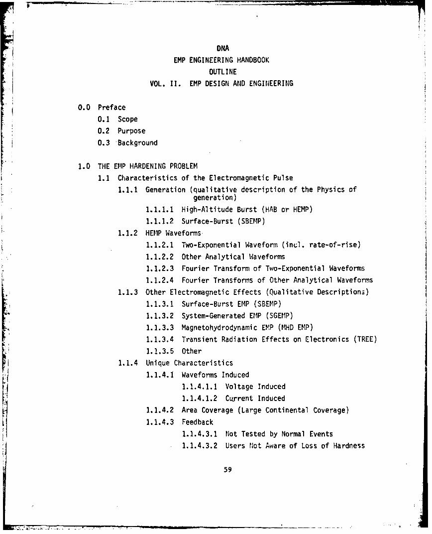
DNAEMP ENGINEERING HANDBOOK
OUTLINE
VOL. II. EMP DESIGN AND ENGINEERING
0.0 Preface
0.1 Scope
0.2 Purpose
0.3 -Background
1.0 THE EMP HARDENING PROBLEM
1.1 Characteristics of the Electromagnetic Pulse
1.1.1 Generation (qualitative description of the Physics ofgeneration)
1.1.1.1 High-Altitude Burst (HAB or HEMP)1.1.1.2 Surface-Burst (SBEMP)
1.1.2 HEMP Waveforms
1.1.2.1 Two-Exponential Waveform (incl. rate-of-rise)
1.1.2.2 Other Analytical Waveforms
1.1.2.3 Fourier Transform of Two-Exponential Waveforms
1.1.2.4 Fourier Transforms of Other Analytical Waveforms
1.1.3 Other Electromagnetic Effects (Qualitative Descriptions)
1.1.3.1 Surface-Burst EMP (SBEMP)
1.1.3.2 System-Generated EMP (SGEMP)
1.1.3.3 Magnetohydrodynamic EMP (MHD EMP)
1.1.3.4 Transient Radiation Effects on Electronics (TREE)
1.1.3.5 Other1.1.4 Unique Characteristics
1.1.4.1 Waveforms Induced
1.1.4.1.1 Voltage Induced
1.1.4.1.2 Current Induced
1.1.4.2 Area Coverage (Large Continental Coverage)
1.1.4.3 Feedback1.1.4.3.1 Ilot Tested by Normal Events
1.1.4.3.2 Users N~ot Aware of Loss of Hardness
59

1.2 Interaction with Systems
1.2.1 Coupling to Long Lines (Description of Interaction)
1.2.1.1 Long Aerial Lines (incl. Typical Voc, Is)1.2.1.2 Long Buried Lines (incl. Typical Voc, Is)
1.2.1.3 Radio Towers/Waveguides (incl. Voc, Is)
1.2.2 Intervening Structure (Qualitative Discussion)
1.2.2.1 Shields
1.2.9.2 Mismatches
1.2.2.3 Filters
1.2.2.4 Insulation Breakdown
1.2.2.5 Uncertainties
1.2.3 Coupling to Cables (Qualitative Description)
1.2.3.1 Unshielded Cables
1.2.3.2 Solid-Shielded Cables
1.2.3.3 Braid-Shielded Cables
1.2.3.4 Connectors
1.2.3.5 Other
1.2.4 System Sensitivity (Discussion of Sensitivity Levels)
1.2.4.1 Digital Electronic Voltage/Current Levels
1.2.4.2 Component Damage Levels
1.3 EMP Hardening
1.3.1 Electromagnetic Barrier (Hardening by closed barrier)
1.3.2 Penetrating Conductors (Worst Violators)
1.3.2.1 Power
1.3.2.2 Signal1.3.2.3 Control
1.3.3 Apertures (Openings in Shield)
1.3.3.1 Personnel Doors1.3.3.2 Equipment Doors
1.3.3..3 Ventilation
1.3.3.4 Fabrication
1.3.4 Shield Walls (Metal of workable thickness usually adequate)
1.3.4.1 Diffusion1.3.4.1.1 Walls
1.3.4.1.2 Long Slender Shields (Cable Shields)
60
- ' .

1.3.5 Inherent Hardness of Equipment
I 1.3.5.1 Typical Box/Rack Damage Levels
1 1.3.5.2 Typical Box/Rack Upset Levels
61

2.0 PRINCIPLES OF EMP HARDENING
2.1 EM Barriers
2.1.1 Description of Barrier (closed Topological Surface)
2.1.2 Components of Barrier
- I2.1.2.1 Data on Shields
2.1.2.2 Data on Shield Materials
*2.1.2.3 Long Wire Treatments (inc. data)
2.1.2.4 Aperture Treatments (inc. data)
*2.1.2.5 Spacing
* I2.1.2.6 Orthogonalization
2.1.3 Requirements on Barrier (Fundamental Functions)
2.2 Placement of Barriers
2.2.1 Two-level Barrier (Usually Follows Natural Surfaces)
2.2.1.1 First Level at Walls of Facility or Room
2.2.1.2 Second Level at Equipment Housing
2.2.1.3 Use Existing Metal Structure Where Possible
2.2.2 Single-Level Barrier
2.2.2.1 Single Level at Equipment
2.2.2.1.1 All Hardening at the Equipment Level
2.2.2.1.2 System Hardening Independent of Building
2.2.2.2 Single Level at Building
2.2.2.2.1 All Hardening at Building Level2.2.2.2.2 Hardening Independent of
Equipment Sensitivity2.2.3 Partial Barrier
2.2.3.1 Equipment Partially Hardened
2.2.3.2 Assumed Losses Elsewhere
2.2.3.3 Not Recommended
2.2.4 Other Considerations2.2.4.1 Ability to Test2.2.4.2 Ability to Maintain
2.2.4.3 Compatibility with Manufacturing/Construction Practices
2.2.4.4 Effects on Approach
62
~~ 7 Z, MUM"~ --

2.3 Effectiveness Required of Barriers
2.3.1 Measuring Effectiveness
2.3.1.1 Measure System EMP Response (or Immnunity)
2.3.1.2 Do Not Measure Shielding-Effectiveness
2.3.1.3 Commnents on MIL-STD-285
2.3.2 Two-Level Barrier2.3.2.1 Allocation of Hardening Between Barriers
2.3.2.2 Effectiveness Required of Each Barrier
2.3.3 Single-Level Barrier
2.3.3.1 Effectiveness Required at Equipment Level
243.3.2 Effectiveness Required at Facility Level
2.4 Integration with Other EM Requirements
2.4.1 EM Control
2.4.1.1 Techniques Apply to All EM Controls
2.4.1.2 Integration is Feasible
2.4.2 Grounding Topology
2.4.2.1 Grounding Conductors Should Not Penetrate Shields
2.4.2.2 Ground Wires Can Distribute Interference
2.4.2.3 Proper Treatment of Ground Wires
2.4.3 Use of Existing Assets
2.4.3.1 Take Advantage of Existing Cabinets
2.4.3.2 Take Advantage of Metal Liners
L.4.3.3 Use Isolation of Power Supplies
2.4.3.4 Use Isolation of Transformers
2.4.3.5 Use Isolation of Converters
2.4.3.6 Use Characteristics of Tuned Circuits
2.4.3.7 Beware of Irrational Practices
63

3.0 FACILITY. LEVEL HARDENING CONCEPTS3.1 Characteristics Peculiar to Facility Level
3.1.1 Large Transients (Voc, Isc)
3.1.1.1 Power Lines
1 )3.1.1.2 Cables
3.1.1.3 Towers
3.1.1.4 Waveguides
3.1.2 Large Apertures
3.1.2.1 Personnel Doors
3.1.2.2 Windows
3.1.2.3 Equipment Doors
3.1.2.4 Long Structural Seams and Joints
3.1.3 Construction Techniques
3.1.3.1 Conventional Techniques May Not Be Adequate
3.1.3.2 Some EMP-Mods Can Reduce Overall Costs(Rebar, for example)
3.1.4 Configuration Control
3.1.4.1 Facility Controls Often Loose
3.1.4.2 No Control Over Major Collectors of EMP Energy
3.1.4.2.1 Power Lines
3.1.4.2.2 Cables
3.1.4.2.3 Fences Off Premises
3.1.5 Other Sources
3.1.5.1 Nearby Transmitters3.1.5.2 High-power Transmission Lines
3.1.5.3 Electronic Warfare
3.2 Framework of Barrier (Shield Walls)3.2.1 Walls (Continuous Metal Walls Adequate)
3.2.2 Entry Panel3.2.2.1 Control Current Flow Over Shield
3.2.2.2 Confine Currents to Well Designed Region
3.2.3 Shield Excitation
3.2.3.1 Wave Excitation3.2.3.2 Excitation of Appendages
:1 64

3.2.4 Surface Excitation
3.2.4.1 Typical Current on Skin
3.2.4.2 Typical Charge Density on Skin/At Apertures
3.2.5 Evaluation (Method of Measuring Effectiveness)
3.2.5.1 Barrier Threat3.2.5.2 System Relatability
3-2.5.3 Scaling
3.3 Penetration Treatments
3.3.1 Non-Linear Voltage Limiters
3.3.1.1 Types
3.3.1.2 Characteristics3.3.1.3 Peculiarities
3.3.1.3.1 Intermodulation Products
3.3.1.3.2 Frequency Shifting
3.3.1.3.3 Relaxation Oscillation
3.3.1.3.4 Extinguishing Characteristics
3.3.2 'ýilters3.3.2.1 Properties of Power Line Filters
3.3.2.2 Interaction with Transformers
3.3.2.3 Effects on System Resonances
3.3.3 Isolators
3.3.3.1 High-Voltage Insulation Requirements
3.3.3.2 Use of Plastic Plumbing3.3.4 Grounding
3.3.4.1 No Penetration of Shields
3.3.4.2 Shields To Be Closed, not grounded3.3.5 Measure of Effectiveness
3.3.5.1 How to Measure Effectiveness of Penetration Treatment3.3.5.2 How Effectiveness of Penetration Treatment is Related
to Threat and Barrier Design
65

3.4 Aperture Treatments3.4.1 Deliberate Apertures (Doors, Windows, Hatches)
3.4.1.1 Treatment Techniques
3.4.1.2 Data on Effectiveness of Techniques
3.4.2 Apertures of Construction3.4.2.1 Riveted and Bolted Joints/Seams
3.4.2.2 Wire Mesh-. I3.4.2.3 Rebar
3.4.2.4 Data on Effectiveness
3.4.2.5 Recommend at Gn~3.4.3 Measure of Effectiveness
3.4.3.1 How To Measure Effectiveness of Aperture Treatments
3,4.3.2 How To Relate To Threat on Barrier Design
3.5 Allocation
3.5.1 Parallel Paths
3.5.1.1 Priority of Treatments and Compromises
3.5.1.2 Making Treatments Effective3.5.2 Barrier Levels (How Much Barrier Effectiveness Should Be
Allotted to Each Barrier Level)
66
-Now

4.0 EQUIPMENT LEVEL HARDENING CONCEPTS
4.1 Characteristics Peculiar To Equipment
4.1.1 Size (Equipment is smaller than facility)
4.1.2 Incident Transients
4.1.2.1 V and I Usually Smaller at Equipment
4.1.2.2 Small Size Gives Less Intercept Area
4.1.3 Identification of Compromises
4.1.3.1 Penetration and Apertures Usually Easier to Identifyat Equipment Level
4.1.3.2 Number of Penetrations May Be Larger at Equipment Level4.1.4 Shield Topology
4.1.4.1 May Be Complicated if Shielded Interconnecting CablesAre Used
4.1.4.2 Box Substitutions May Not Be Equivalentr4.1.5 Inherent Immunity
4.1.5.1 Some Hardness Built-in To Withstand Other Requirements
4.1.5.2 Interference Control Standards for Equipment Exist
4.1.6 Relationships of TREE-Hardening to EMP
4.1.6.1 Neutron Hardening Requires Small Junctions (high fT)Which Usually Results in Low Damage-Levels for EMP
4.1.6.2 Radiation Hardening Against "Latchup" Can Help Prevent"EMP Latchup"
4.1.6.3 Other Effects
4.2 Shield Framework
4.2.1 Metal Cabinet Shielding (Can be Adapted)
4.2.2 Entry Panel (Back Plane can serve as single entry panel)4.2.3 Barrier Topology '(Cable Shields/Connectors may be part of
equipment level barrier)
4.3 Penetrations4.3.1 Power Supply Barriers at Penetration
4.3.1.1 Filters
4.3.1.2 AC/DC Rectifiers
4.3.1.3 DC/DC Converters4.3.1.4 Data on Effectiveness and Peculiarities
67

4.3.2 Signal and Control Penetrations
4.3.2.1 Filters4.3.2.2 Commnon-Mode Rejection Devices
4.3.2.3 Liniters
4.3.2.4 Data on Effectiveness and Peculiarities
4.3.3 Grounding Penetrations
4.3.3.1 Ground Leads Should Not Penetrate
4.3.3.2 Shields Should Be Closed, Not Grounded
4.3.4 Other Penetrations
4.3.4.1 Cooling and Heating
L. 4.3.4.2 Hydraulic, Pneumatic, Mechanical Structure and Pipes
r 4.4 Apertures4.4.1 Deliberate Apertures
4.4.1.1 Treatment Techniques
4.4.1.2 Data on Untreated Apertures
4.4.1.3 Data on Treatment Effectiveness
4.4.2 Apertures of Construction
*4.4.2.1 Riveted, Bolted, Spot-welded Seams4.4.2.2 Panel/Drawer Attachment
4.4.2.3 Data on Untreated Apertures
* r 4.4.2.4 Data on Treatment Effectiveness
4.4.3 Measure of Effectiveness
4.4.3.1 How Aperture Compromises and Treatment EffectivenessAre Measured
4.4.3.2 How Effectiveness Is Related to Threat-Level andI; System Design4.5 Allocation of RequirementsII4.5.1 Parallel Paths (Priority of Treatment)
4.5.2 Barrier Levels (How Much Barrier Effectiveness Should BeAllotted to Equipment-Level Barrier)
68

5.0 EVALUATION AND TEST CONCEPTS
5.1 Description of Problem
5.1.1 Relation of Test to Threat/System Design
5.1.1.1 Should Excite System in Way Easily Related to Threat5.1.1.2 Test Results Should be Easily Related to Threat
Response, and System Design Parameters5.1.2 Production Quality Control
5.1.2.1 Tests Conducted During Manufacture5.1.2.2 Assure Containers, Equipment Units are Adequate
5.1.3 Qualification of Components5.1.3.1 Connectors
V5.1.3.2 Cable Shieldsr5.1.3.3 Packaged Equipment
5.2 Quality Control of Containers5.2.1 Excitation (relatable to way system/threat excites container)5.2.2 Response (relatable to internal circuit response)
5.3 Qualification of Equipment
5.3.1 Excitation of Barrier (Threat Relatable Excitation forlImmunity Test)
5.3.2 Detection (Confinement of Internally Generated InterferenceDetected in System Relatable Way--e.g., Current on InterconnectingCables)
5.3.3 Interpretation (Relation of Imm~unity and Confinement DataTo System Interference Control Design)
5.4 Qualification of Facility
5.4.1 Excitation of Facility
5.4.1.1 Threat Relatability5.4.1.2 Types of Simulators/Sources
5.4.2 Measurement of Response5.4.2.1 Sensors and Detectors for Determining Environment5.4.2.2 Sensors and Detectors for Measuring System Response
5.4.3 Interpretation of Data
69
I > . -. . -. . . - -INV:

6.0 SYCTEM ENGINEERING REQUIREMENTS
(Describes considerations for establishing general overll requirements)
6.1 Survivability Confidence Required
6.1.1 Confidence Needed (Depends on Mission)
6.1.2 Design Margin Required (Depends oni Confidence)6.1.3 Attenuation Required (Depends on Confidence/Margin)
6.1.4 Alternatives
6.2 Costs/Affordability
6.2.1 Macroscopic Cost Data on Hardening
6.2.2 Parameters that Influence Costs of Construction6.2.3 Costs of Validation/Assessment
6.2.4 Costs of Maintenance/Repair
6.2.5 Life Cycle Costs
6.2.6 Cost Impact of Outages
6.3 EM Integration
6.3.1 EMI/EMC (Deficiencies in Specs, for EMP)
6.3.2 Lightning (Impact on Sizing Components)6.3.3 TEMPEST (Impact on Shielding Topology Selection)
6.3.4 EM (Potential impact on frequency requirements andsizing parts)
6.4 Environmental Requirements
6.4.1 Temperature/Humidity
6.4.2 Altitude
6.4.3 Corro~sion/fungus/dust and sand
6.4.4 Other
6.5 Specifications
6.5.1 Minimum Specification Content (Outline)6.5.2 Specification Format
6.5.3 Sample Specification
70

6.6 Precedence/Experience
(Gives Results of Past Programs)
6.6.1 APACHE Program
6.6.2 SAFEGUARD Program
6.6.3 MINUTEMAN Facilities
6.6.4 DSP GDS Facilities
6.6.5 Other
6.7 Schedules
6.7.1 Schedule Considerations and Constraints
6.7.2 Typical Schedules
71

7.0 SYSTEM E,'GINEERING DESIGN7.1 System Modeling/Analysis Techniques
7.1.1 Goals of the Analysis (Alternatives)
7.1.2 Limitations of Analysis
7.1.3 Benefits of Analysis
7.1.4 Summary of Pros and Cons of Analysis7.1.5 Alternative Analysis Methodologies
7.1.5.1 Topological Models7.1.5.2 Macroscopic Models (Simplified Overall Model)
7.1.5.3 Microscopic Transfer-Function Models
7.1.5.4 Microscopic Lumped-Parameter Models
7.1.6 Pros and Cons of Alternative Models
7.2 Reliability Considerations
7.2.1 Initial Reliability (No Degradation)
7.2.2 Impact of Environmental Degradation
7.2.2.1 Degrading Factors
7.2.2.2 Design Techniques To Minimize Degradation
7.2.3 Impact of Maintenance
7.2.3.1 Benefits of Periodic Tests
7.2.3.2 Benefits of Preventative (Periodic) Maintenance
7.2.3.3 Tracking Degradation With Time
7.2.3.4 Impact and Importance of Man-induced Failures(the "Diddle-Factor")
7.3 Maintainability Considerations
7.3.1 Fault Detection
7.3.2 Fault Isolation
7.3.3 Speed-of-Repair (Down-time)
7.3.4 Repair Procedures
7.3.5 Maintenance Manuals
72
0 WL A

7.4 Life7.4.1 Life Specifications (number of years)
7.4.2 Corrosion Control Plan7.4.3 Corrosion Control Program
7.4.4 Derating of Components
7.4.5 Design Guidelines for Maximum Life
7.5 'EM Integration
7.5.1 EMI/EMC Design Considerations
7.5.2 Lightning Design Considerations
7.5.3 TEMPEST Design Considerations
7.5.4 E14P Design Considerations
V 7.5.5 Integration of Design Considerations
7.6 Upset Protection/Recovery Techniques
7.6.1 Upset Thresholds vs. System Noise
7.6.2 Automatic Reset Techniques (including limitations)
7.6.3 Manual Reset (including limitations)
L7.6.4 Interface Noise RejectionV7.6.5 Pros and Cons of Alternative Techniques
7.7 System Dependent Tradeoffs
(Discusses system-peculiar considerations)
7.7.1 Military vs. Commercial Facilities (different constraints)7.7.2 Terrain Effects/Water Table (constraints)
7.7.3 Size vs. Penetrations (relative costs)
7.7.4 Packaging (filters, etc.)
7.7.5 Data-rates on Penetrations (constraints)
7.7.6 Power Levels (constraints)
7.7.7 Emergency Power (consiraints, impact)
7.7.8 Human Engineering Constraints7.7.9 Special Antennas for Crew Recreation
73

8.0 CALCULATED THREAT LEVELS
(Gives general results of past work)
8.1 Typical Power Line Transients (Voc, Is)
8.2 Typical Above-Ground Landlines (Telephone, et al)
8.3 Typical Buried Landlines
8.4 Typical HF Antennas8.5 Other Antennas (VHF, UHF, MF)
"8.6 Effects of Filters on Waveforms
.8.6.1 Various Cutoff Frequencies
8.6.2 Various Rolloff Slopes
8.7 Effects of Limiters on Waveforms
8.7.1 Different rates-of-rise
8.7.2 Different Lead Inductances
8.8 Effects of Filters and Limiters Combined
F,
74
Owl ,°-• r- .

9.0 EQUIPMENT SUSCEPTIBILITY LEVEIS(Gives General Results and Ideitifles References)
9.1 Alternative Threshold Levels9.1.1 EMI Susceptibility Levels
9.1.2 System Noise Levels
9.1.3 Normal Operating Signal Levels9.1.,A Verified (by Test) Threshold Levels
.9.1.5 Predicted Threshold Levels
9.1.5.1 Burnout (including limitations)
9.1.5.2 Upset (including limitations)9.1.6 Pros and Cons of Alternatives
9.2 Equipment Level Thresholds
9.2.1 Susceptibility to EMP Incident lPields
9.2.2 Susceptibility to Current on Penetrations
r 9.2.2.1 Upset
9.2.2.2 Semiconductor Device Damage
9.2.2.3 Non-semiconductor Parts Failures
9.2.2.4 Voltage-Induced Failures9.2.3 Summary of Failure Modes and Effects9.2.4 Recommended References
75

ýJi10.0 DETAILED DESIGN DATA AND TRADEOFFS
(Gives Detailed Engineering Design Data)
10.1 Shielded Enclosures
10.1.1 Effectiveness vs. Materials/Thickness
10.1.2 Effectiveness vs. Construction Method
(welded, bolted, riveted, wire-mesh)10.1.2.1 What constitutes an adequate weld10.1.2.2 What represents good bolting-practice
10.1.2.3 What represents good riveting-practice
10.1.2.4 Bonding of Wire-mesh, and rebar
10.1.3 Effectiveness vs. Time (degradation)
10.1.4 Effectiveness vs. Initial Cost
10.1.5 Effectiveness vs. Maintenance Costs
10.1.6 Effectiveness vs. Life
10.1.7 The Impact of Apertures
10.1.7.1 Effect of Size
10.1.7.2 Effect of Shape
10.1.7.3 Effect of Location
10.1.7.4 Effect of Cable Proximity
10.1.7.5 Summuiary of "IDo's and Don'ts"
10.2 Shielded Cables
10.2.1 Effectiveness vs. Solid or Braid
10.2.2 Effectiveness vs. Materials/Thicknesses
10.2.3 Effectiveness vs. Time (corrosion, et al)
10.2.4 Effectiveness of Cable Connectors
10.2.5 Effectiveness of Cable Systems
(Impact of combining shield, connector and system
installation factors of length, number of branches, etc.)
76
*--,*~~~m - --- , Lý

10.3 Filters
10.3.1 Advantages and Disadvantages
10.3.2 Effectiveness of Bypass Capacitors (including resonances)
10.3.3 Effectiveness of Multi-Section Filters (L,T,7r,ladder,etc.)
10.3.3.1 Effect of Source and Load Impedances
10.3.3.2 Effects of Loss Parameter (hybrid filter)
10.3.3.3 Capacitor-Input vs. Choke-Input
10.3.3.4 Comion-mode vs. Differential (orthogonality)
10.3.3.5 Damage-levels and damage mechanisms (surge-ratings)
10.3.3.6 Reliability (TITFB's, deratings, etc.)
10.3.3.7 Packaging Constraints
10.3.3.7.1 Need for RF-barrier
10.3.3.7.2 Maintainability Considerations (Plug-in,
versus other)
10.3.3.8 Size/Weight/Cost Summary
10.3.4 Effectiveness of Filter-pin Connectors
10.3.4.1 Effect of Load Impedance
10.3.4.2 Damage Levels
10.3.4.3 Effectiveness of Different Types
10.3.4.4 Reliability (including MTBF's)
10.3.4.5 Size/Weight/Cost Summary
10.3.5 Recommended Filter Designs
10.3.5.1 Power Lines
10.3.5.2 Landlines
10.3.5.2.1 Low Data-rate
10.3.5.2.2 High Data-rate
10.3.5.3 Antennas
77
S. .. . ;.-m-

10.4 Surge-Limiting Devices10.4.1 Advantages and Disadvantages (General)
10.4.1.1 Non-Linear Effects (Spectrum shift, extinguishing,
rate-of-rise dependence, inter-modulation effects,
waveform and level dependence, etc.)
10.4.1.2 Limitations (including inability to prevent upsets)
10.4.1.3 Test Requirements (Assessment, validation,
surveillance)
10.4.1.4 Reliability (including MTBFs)
10.4.1.5 Geniral Cost/Size/Weights vs. Effectiveness
10.4.2 Alternative Types and Applications
10.4.2.1 Spark-gaps (high-levels)
10.4.2.2 Metal-Oxide Varistors (MOV) (moderate levels)
10.4.2.3 Tranzorbs (moderate-to-low levels)
10.4.2.4 Zener Diodes (moderate-to-low levels)
10.4.2.5 CurrentLimiting (circuit applications)
10.4.2.6 Hybrid Combinations (Antenna Applications)
10.4.3 Effectiveness of Spark Gaps
10.4.3.1 Common-mode vs. Differential
10.4.3.2 Effectiveness vs. rate-of-rise (percent overshoot)
10.4.3.3 Effectiveness vs. Lead Length (percent overshoot)
10.4.3.4 Extinguishing Requirements
10.4.3.5 Selection of Breakdown Voltage (allowance for noise)
10.4.3.6 Effectiveness vs. Cost (special fast devices)
10.4.3.7 Failure-modes and effects (incl. MTBFs)
10.4.3.8 Typical Fall-times on Firing (noise generation)
10.4.3.9 Test Techniques
10.4.3.10 Size/Weight/Cost Summary10.4.3.11 References
78

10.4.4 Effectiveness of MOV Devices
.1 10.4.4.1 Effectiveness vs. rate-of-rise
10.4.4.2 Effectiveness vs. lead length
10.4.4.3 Failure-modes and Effects (including MTBFs)
10.4.4.4 Typical fall-times
10.4.4.5 Test Techniques
10.4.4.6 Size/Weight/Cost Summary
10.4.4.7 References
10.4.5 Effectiveness of Tranzorb Devices
10.4.5.1 Effectiveness vs. rate-of-rise
10.4.5.2 Effectiveness vs. lead length
10.4.5.3 Failure Modes and Effects (including MTBFs)
10.4.5.4 Typical fall times
10.4.5.5 Test Techniques
10.4.5.6 Zero-lead-length configurations
10.4.5.7 Size/Weight/Cost Summary
10.4.5.8 References
10.4.6 Effectiveness of Zeners and Other Diodes
10.4.6.1 General Characteristics for Limiting Applications
10.4.6.2 Limitations
10.4.7 Effectiveness of Current Limiting
10.4.7.1 Typical Applications
10.4.7.2 Limitations
10.4.8 Effectiveness of Hybrid Combinations
10.4.8.1 HF Antenna Examples
10.4.8.2 Special Circuit Applications
79

10.4.9 Limiter-Fi.ter Combinations
10.4.9.1 Power-Line Examples
10.4.9.2 Landline Examples
10.4.9.2.1 Low Data-Rate
10.4.9.2.2 High Data-Rate
10.4.9.3 VHF Antenna Examples
10.4.9.4 UHF Antenna Examples
10.5 Fibre-Optics
10.5.1 Advantages and Disadvantages
10.5.2 Effectiveness
10.5.3 Limitations (Must Protect Input and Output)
10.5.4 Reliability
10.5.5 Size/Cost/Weight Summary
10.6 Non-Electrical Penetrations
10.6.1 Alternative Bonding Techniques
10.6.2 Corrosion-protection of Bonds
10.6.3 Bond Impedance vs. Frequency
10.6.4 Non-Conducting Breaks in Conductors (including limitations)
10.6.5 Examples of Boniding Techniques
10.6.5.1 Water Pipes
10.6.5.2 Sewer Pipes
10.6.5.3 Cooling Lines
10.6.5.4 Waveguide
10.6.5.5 Fuel Lines
80
. ...... 7

11.0 HARDNESS ASSURANCE
(Describes Program to Assure Hardness Quality During Manufacture and
Construction)
11.1 Equipment Inspection Procedures11. 1. 1 Hardware Tests
11.1.2 Hardware Inspection
11.2 Facility Inspection Procedures
11.2.1 Tests of Elements
11.2.1.1 Example, Sniffer-Test of Shield Seams
11.2.1.2 Example, Electrical Tests of Each Bond
11.2.1.3 Example, Functional Test of Filter Boxes
11.2.1.4 Example, Current-Injection Tests on Power Lines
11.2.2 Verification by Visual Inspection
11.3 Inspection Requirem~ents
11.3.1 Equipment Drawings and Specifications
11.3.2 Facility Drawings and Specifications
11.3.3 Special Procedures
81

OEM
12.0 HARDNESS VERIFICATION AND TESTS
(Describes Test Program to Verify Hardness After Construction)2
12.1 EIP Simulators
12.2 CW Measurements and Test Equipment
12.3 Current-Injection and Test Equipment
12.4 Assessment Methodology Alternatives
12.4.1 Proof Test Approach
12.4.2 Statistical Sampling Approach
12.4.3 Measurement of All Penetrations
12.4.4 Other Approaches
12.4.5 Pros and Cons of Alternative Techniques
12.5 Calibration of Hardness Monitoring System
12.6 Sample Test Plans
12.7 References
82

71 13.0 HARDNESS SURVEILLANCE AND HARDNESS MAINTENANCE
(Describes Design Considerations to Support Subsequent HS/HM Activities)
'i, 113.1 Importance of Failure Monitoring
13.2 Need for Early Planning
I 13.3 Need for Built-in Test Points
* 13.4 Designer Should Suggest Concepts
13.5 Designer Should Identify EApected Degradation
13.6 Advantages of Built-in Monitor System
13.7 Fault Detection v~s. Fault Isolation
13.8 Repair vs. Replacement
13.9 Shield Repair Techniques
13.10 Hardness Surveillance/Hardness Maintenance Plan
83
_7 j --------A

14.0 DEVELOPING TRAINING AIDS
14.1 Need for EMP Awareness Training
14.2 Need for Maintenance Procedures
14.2.1 Diagnostic Techniques
14.2.2 Repair Techniques
14.3 Past Examples
14.4 Sources and References
It
I 84

15.0 LOGISTIC SUPPORT
15.1 Assuring Adequate Spare Parts15.1.1 Problems with Procuring "Old" Parts Designs15.1.2 Problems with Substituting Parts Types15.1.3 Estimating Spares Requirements
15.2 Integration of Logistic Support with Existing LogisticsOrganization/Current Programs
15.3 Logistic Support Plan15.3.1 Preparation Guidelines
15.3.2 Sample Outline
15.4 Logistics EMP Reporting Requirements
85

16.0 ESTIMATING LIFE CYCLE COSTS
16.1 General Discussion
16.2 Existing Mathematical Models
- 16.2.1 Parametric Models16.2.2 Detailed Calculation Models
16.2.2.1 Input Variables
16.2.2.2 Outputs
16.3 Typical LCC Tradeoffs
16.4 Typical LCC Results
16.5 References and Other Sources
F 86

APPENDIX D
Draft Outline for
I DNA
EMP ENGINEERING HANDBOOK FOR GROUND BASED FACILITIES
Volume III
OPERATIONS AND MAINTENANCE
T. A. MARTIN (IIT Research Institute)
S. J. COLOMBO (Boeing Aerospace Co.)
D. L. DURGIN (Bcoz Allen & Hamilton, Inc.)
87
•'Lo' .A - ,- -:• . ,.-- - - _- • .. . . . .

Preface
Operations and Maintenance Handbook
During the operational lifetime or deployment phase of an EMP protected C3facility, the responsibilities of the Operations ai~d Maintenance personnel are tocontinually maintain, validate, and assure the EMP hardness integrity of thefacility throughout its operational lifetime. The purpose of this handbook is toprovide a compendium of the reference material, information, and guidelines thatare considered relevant to O.&M. managers, engineers, and technicians charged withthe task of meeting these responsibilities.
The material content included in the handbook is organized around major sub-ject and/or task areas identified as being of concern to the O.&M. specialists inmeeting the EMP hardness assurance and maintenance objectives throughout the 1operational lifetime of the facility. These major topics of interest include:
o, EMP Hardness Data Base for the facilityo General O.&M. Considerations
o Operations and Maintenance Planningo Test/Inspection Procedures
o Test Equipment for Hardness Surveillanceo, Maintenance techniques, procedures and control
o Personnel Training
o Documentation and record keeping
In presenting the material, information and data contained in the handbookin each of these subject areas, efforts have 'been made to avoid slanting it suchas to bias the reader or making decisions for him. Hence the emphasis is put onidentifying and presenting as many of the available and/or known approaches,options, and alternatives as possible together with sufficient supporting informa-tion to facilitate the selection of an approach or alternative method suitableto the reader's need. Also, the organizational structuring of the handbook interms of these major subject areas facilitates the anticipated up-dating thatwill be required to include new material, new techniques, and new approachesas well as delete obsolete material.
It is important to note that some of the subject areas are not addressedsolely to the O.&M. specialists. For instance, it is recognized that issuesconcerning the facility EMP Data Bases and Planning for O.&M. operations areVý major concern to the developers and designers of the EMP hardening facility.They are the ones who will most likely be responsible for the development ofboth. However, since they are both a necessary input before commencing O.&M.,it is felt that O.&M. specialists should be familiar with these data base andplanning issues and be made aware of the factors considered in developing them.
88
fJ

Summary Outline (1st Revision)
OPERATIONS AND MAINTENANCE VOLUME
1.0 INTRODUCTION
1.1 Overview of Operations and Maintenance (O.&M.) Problems
1.1.1 Purpose of O.&M. (e.g. to continually validate, maintainand assure the "as-built" EMP hardness integrity of thefacility throughout its operational lifetime).
1.1.2 Scope of Handbook Issues
o Designing to O.&M. Requirements/Constraints
o Protection Element Degradation
1 o O.&M. Planningo Hardness Surveillance (test techniques,
procedures, equipment)
o Hardness Maintenance
o Management/Training/Documentation
1.1.3 Intended Users
o O.&M. Specialistso EMP Hardening Design Engineers
o Managers
1.2 Background
1.2.1 Lessons Learned from Prior O.&M. Experiences
o SAFEGUARDo Europe/NATO
o Others
1.2.2 Reasons for O.&M.
1.3 Reference Documents
1.3.1 Reference Management and Design Handbooks
1.3.2 Vols I & II of this Planned DNA EMP Engitihering HandbookSeries
89

1.3.3 Other Reference Material
o Facility EMP Hardening Design Description (assumed to beprovided when facility is turned over to O.&M. personnel).
o EMP Protection Element Performance Data Base (availableat beginning of operations phase).
1.4 Definitions
1.4.1 Words
1.4.2 Terms
2.0 GENERAL O.&M. CONSIDERATIONS
(Addresses the O.&M. requirements, factors, and constraints to be consideredduring the EMP hardening design and construction phase.)
2.1 Hardening Design Factors from an O.&M. Point of View
2.1.1 Protective Element and/or Technique Degradation
2.1.2 Ease/Cost of Monitoring/Maintaining PerformanceOver Operatic al Lifetime
2.1.3 Initial vs. HS/HM Cost Trade-Offs
2.1.4 Operational Limitations/Constraints
2.1.5 Ease/Cost of In-Situ Test/Inspection
2.1.6 Requirements to Detect Faults, Degradation, etc.
2.2 Construction Monitoring and Acceptance
2.2.1 Conformance to Design
2.2.2 Construction/Implementation/Installation Monitoring,Testing and Control
2.2.3 Facility Hardness Verification Testing
2.3 Facility Specifications and Design Data Package
2.3.1 Preparation of a complete description of the design methodologyutilized as well as the specific protective measures, devicesand/or techniques employed to harden the facility against EMP.
2.3.2 A Data Base that characterizes the EMP hardness level of the
facility in terms of acceptable performance for each of thespecific EMP protective measures, devices and/or techniques
employed.
90

2.3.3 Define/Identify expected problem areas during O.&M.
3.0 OPERATIONAL PERFORMANCE OF EMP PROTECTION ELEMENTS
3.1 EMP Hardened Facility Description
Describe the typical approaches used to EMP harden a facility,emphasizing the various design options, topological/configurationcontrols, construction techniques, components and techniques utilizedto achieve a specified hardness level. (This section could becommon to Volumes II and III).
3.2 EMP Protection Element Degradation (Identifies and discusses thetypes and causes of performance degradation in the various EMPprotective measures/devices used in hardening a facility).
3.2.1 Building Shields and Apertures
3.2.2 Enclosure Shields (cabinets, racks, chassis, etc.)
3.2.3 Cable Assemblies (connectors, shields, splices, etc.)
3.2.4 Penetration Control Devices
o Bonding Welds
o Bonding Straps
o Gasketing/Screening Elements
I o Doors, Windows, Ducts
o Filters
o TPD's
(Note: Detailed functional and performance descriptions should be in1.7 in Volume II and the above section focuses on degradation andfailure related issues.)
3.3 Configuration Control Requirements
Describe the elements of a configuration control program to precludehardness degradation due to facility or equipment changes, modificationand re-design.
3.4 Reliability Considerations
3.4.1 Nominal MTBF
3'.4.2 Impact of HS/HM on System/Equipment MTBF.
191 T! 91
I.

4.0 FACILITY OPERATIONS AND MAINTENANCE PLANNING
4.1 Review/Develop Awareness of Baseline Facility EMP Specificationsand Qualification Data
4.1.1 Initial EMP Hardness Status of Facility
o Hardening Design Methodology
o Protective Measures/Techniques Employed
4.1.2 Facility Acceptance and Hardness Verification Reports
4.1.3 Protective Device Performance Specifications/Data Base
4.1.4 Annotated Hardening Design/Construction/InstallationDrawl ngs
4.1.5 Manuals (Operating, Service, Repair, etc.)
4.2 Configuration Control
4.2.1 Describe Purpose and Rationale for
4.2.2 Elements of Concern
o Equipment Changes (re-location, part substitution,additions, deletions, etc.)
o Changes in Cable Type, Length, Routing, etc..,
o Modification or Changes in Shielding Structures
o Changes in EMP protective element typeso Modification/Redesign at Facility, Intra-Facility
and/or Equipment Level
4.2.3 Define Control FunctionsI. o Periodic Facility Surveillance/Inspectiono Monitor/Control Changes
o Update Documentation/Specifications to include_f Approved Changes, Modifications and Re-Designs
o Monitor/Control Repair Activities
4.3 Integrated Hardness Surveillance/Hardness Maintenance Plan
4.3.1 Identify Facility Featuires to be Monitored and Maintained
o Shields (envelop, cable, EMP vaults, cabinet shields, etc.)
o EMP protective devices (TPD's)
o Aperture Control Devices (doors, doorways, vents, gaskets,honeycomb structures, etc.)
92
"..

o Grounding/Bonding Configurations
o Facility Configuration Control Activities
o Equipment Susceptibility
4.3.2 Select Hardness Surveillance Procedures
o Inspection and Monitoring
o Test
o Integrate with Standard Surveillance Practice
o Periodic "Tiger Team" Surveillance/Testing
4.3.3 Define Facility Equipment, Personnel, and Training Requirements
4.3.4 Define Criteria for Acceptance and Decision to Repair
4.3.5 Define Repair/Maintenance Procedureso Preventative Maintenance
o Relation to Standard Maintenance Procedures
o Routine Repair
o Major Repair, Modification or Re-Design
4.3.6 Post-Repair Verification Tests
o Assure Hardness Quality
o Establish Data Base for Subsequent HS/HM
4.4 O.&M. Management Plan
4.4.1 Resource Allocation
o Staffing Assignmentso Budget Appropriations
o Test Equipment/Instrumentation Provisions4.4.2 Data/Documentation/Record Keeping Requirements
o EMP Protection Status Tracking
o Modification/Repair Record
"o Feedback to Designers
. 4.4.3 Procurement/Re-Procurement Control Procedures
o Spare Parts
o Repair Parts
I o Instrumentation/Test Equipment
93
". . .

* I4.4.4 Facility Hardness Status Review
o Periodic Assessment of Surveillance Data/Reports
o Note Observed Performance Degradation
o Identify Pending Problems (i.e., trends indicatingthat repairs may be needed at some later date)
o Decision to Repair, Modify, Change, etc.
4.4.5 Scheduling of HS/HM Task Activities
o Establish Surveillance Inspection/Test Schedules
o Frequency and Type of Routine and/or PreventativeMaintenance
o Approval Requirement to Repair/Modify/Design
o Training/Re-Training
o Test Equipment/Instrumentation Calibration
5.0 HARDNESS SURVEILLANCE TEST/INSPECTION TECHNIQUES AND PROCEDURES
Discuss hardness surveillance requirements and why normal facility surveill-ance may not reveal EMP hardness degradation.5.1 Techniques for Detecting Compromises/Degradation in Bonding Integrity
5.1.1 Changes in Grounding Configuration (i.e. groL-nd loops, etc.)
5.1.2 Operational Changes That Result in Improper Ties BetweenEMP, Signal and/or Safety Grounds
5.1.3 Changes in Bonding Impedance (ruptures, corrosion, frequentconnect/disconnect, etc.)
5.1.4 Wear Between Contacting Metal Surfaces
5.2 Shield Surveillance Techniques (Discuss typical facility shieldingschemes, types and causes of degradation in shield quality, andmethods/techniques for detecting such degradation.)
5.2.1 Building Shields (include door, window and duct shields)
5.2.2 Enclosure Shields (cabinets, EMP vault, etc.)
5.2.3 Cable Shields (conduit, ducts, braid, etc.)
5.2.4 Gaskets, Fingerstock, Conductive Epoxies, etc.
94
S I Ir

5.3 Penetration Protection Device Surveillance Techniques
(Discuss typical penetration protection devices, types and causesof degradation in their performance, and methods/techniques formeasuring and detecting such degradation)
5.3.1 Filters
o Power Systemso Antenna Systems
o Signal Lines
o Mechanical Systems
5.3.2 Surge Arresters/Limiters
o Power Systems
o Antenna Systems
o Signal/Communication Lines
5.3.3 Isolation Techniques/Devices (Transformers, relays,cable/wire routing, etc.)
o Power Systems
o Antenna Systems
o Signal /Communication Lines
5.4 Susceptibility Measurement Techniques
6.0 HARDNESS SURVEILLANCE TEST EQUIPMENT
Discuss the characteristics, operations, and limitations of the varioustest/inspection equipment (electrical, physical, chemical etc.) for usein EMP hardness surveillance
6.1 Shieid Performance/Quality Measurement Equipment
6.1.1 Shield Excitation Equipment
t o EMP SimulatorsK o CW Simulators/Illuminators (discrete and/or pulsed RF)
o Current Injection Devices (CW, transient, pulsed, etc.)
~iio Magnafluxo Non-Electrical (dyes, etc.)
o X-ray
9-5
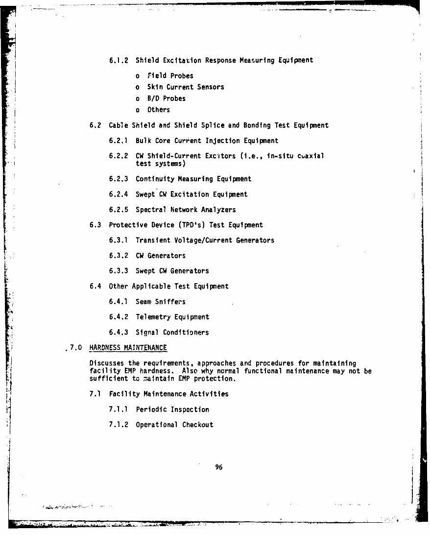
6.1.2 Shield Excitation Response Measuring Equipment
o Field Probes
o Skin Current Sensors
o BID Probes
o Others
6.2 Cable Shield and Shield Splice and Bonding Test Equipment
6.2.1 Bulk Core Current Injection Equipment
6.2.2 CW Shield-Current Excitors (i.e., in-situ cuaxialtest systems)
6.2.3 Continuity Measuring Equipment
6.2.4 Swept CW Excitation Equipment
6.2.5 Spectral Network Analyzers
6.3 Protective Device (TPD's) Test Equipment
6.3.1 Transient Voltage/Current Generators
6.3.2 CW Generators
6.3.3 Swept CW Generators
F 6.4 Other Applicable Test Equipment
6.4.1 Seam Sniffers
6.4.2 Telemetry Equipment
6.4.3 Signal Conditioners
7.0 HARDNESS MAINTENANCE
Discusses the requirements, approaches and procedures for maintainingfacility EMP hardness. Also why ncrmal functional maintenance may not besufficient to maintain EMP protection.
7.1 Facility Maintenance Activities
7.1.1 Periodic Inspection
7.1.2 Operational Checkout
96
7I.7

7.1.3 Testing
o Regularly Scheduled Testing to Measure/VerifyPerformance of Specific Hardness Features
o Troubleshooting/Fault Location
So Post Repair/Modification Tests
o Reference Standard Test Specifications andProcedures Whenever Applicable
o Fault Detection
o Fault Isolation
7.1.4 Preventive Maintenance
7.1.5 Documentation/Record Keeping
o Performance Data
o Cost Data
o Feedback to Designers/Managers
7.1.6 Hardness Status Review
o Periodic reviews to assess surveillance data,identify and/or anticipate failures, trackperformance degradation, etc.
o Decision to Repair/Modify
7.1.7 Integration of Activities with Other Facility
Inspection and Operational Checkouts
7,2 Repair/Modification Procedures, Control and Monitoring
7.2.1 Major Platform/Facility Repairs
o Shields (envelop, EMP vault, entry-ways, etc.)
o Penetration Control Devices/Techniques
o Configuration Changes - Allowable/Unacceptable
o Acceptable R2pair/Modifiatien Options
o What Facility Repairs Can Impact EMP ProtectionPerformance?
7.2.2 Intra-Facillty Repairs
o Intra-Facility Repairs That Can Have Impact onEMP Protection Performance
o Cable/Cable Shield Repairs/Replacement
97V

* o Irterior Room/Compartment Shield Repairs
o Ground System
o Cable Shield to Connector Bonds
7.2.3 Subsystem (Black Box) Repairs
o Effect of Subsystem/Black Box Repairson EMP Protection
o Parts Selection, Substitution, Control, etc.
o Gasket Replacemento Signal/Safety/EMP Ground System Changes
o Adherence to Established Grounding Philosophy
7.2.4 Post-Repair Hardness Verification Testing
o Assure Adequate Performanceo Provide Performance Measurement Data Base
for Subsequent Surveillance
7.3 Operations
7.3.1 Standard Operational Procedures
o Reprogram/Restart Due to Upset of Power
o Communications Link Upset - options based on systemconfiguration, alternate links, etc. (i.e., haveplan available)
o Primary Power to Emergency Power Switchover Procedures
o Operational Do's/Don'ts (i.e., keep shield doors closed,don't circumvent protective systems, etc.)
7.3.2 Fault Isolation Procedures/Practices
o Is System Outage Due to Upset/Damage?
.1o On-Line Repair/Reset Practices
o Established On-Line Test Procedures and Equipments
Do o's/Don'ts - actions which would degrade hardness level(e.g., adding unprot.ected cable entry for test or non-critical function, etc.)
98
98+
E~t-

! ~//
7.3.3 Outage/Maintenance Log Keeping
o Outages /*1 o Preventive Mainuenance/Tests
o Repairso History for Future Periodic Maintenance Sc/eduling,
etc. /
o Feedback to hardening designers
8.0 PERSONNEL TRAINING /8.1 Overview of EMP Problem and the Need fnr Protection
8.2 Goals/Responsibilities of O.&M. Personnel in Maintaining "Built-In"EMP Protection
8.3 Review of EMP Hardening Design Approach, Techniques and DevicesIncorporated to Harden the Facility
8.4 Discussion of Causes/Sources of Hardness Degradation
o Natural (corrosion, wear, etc.)o Man-Made
99
99

Distribution LUst
Assistant Secretary of Defense Defense Technical InformationComm. CmD. Cont & Intelligence Center, Cameron StationWashington, D.C. 20301 Alexandria, Va. 22314
1 cy Attn: Programs & Resources (12 if open publ. otherwise 21 cy Attn: Surveillance & Warning 12 cy Attn DD
Rys 1M 3C0001 cy Attn: Telecomm Systems Commander1 cy Attn: Assistant Director Field Command
(Sys) Defense Nuclear AgneyKirtland APB. New Mexico 87115
Commander in Chief, Pacific 1 cy Attn FCPRUton 28Camp H. M. Smith, Hawaii 96A61 Chief
5 cys Attn: C3SRD Vield CommandDefense Nuclear Agency
Director Livermore BranchDefense Communications Agency P.O. Box RAn L-317Washington, D.C. 20305 Livermore, Calif. 94550
(ADR CNWDI: Attn Code 240 FOR) 1 cy Attn FCPRL1 cy Attn: Code 1O1B
Joint Chiefs of StaffI cy Attn: WWHCCS System Eaginter Washington, D.C. 20301
1 cy Attn J-3 WWMCCS &Commander TelecommunicationsDefense Communications Agency 1 cy Attn J-5 Nuclear DivisionPacific Area 1 cy Attn SAGA Av eDn36Wheeler AFR, Hawaii 96854 1 cy Attn C3u nvaluation Office
1 cy Attn: CommanderJoint Strategic Connectivity Staff
Defense CoIntcations Engineer Offutt AFB, Ne 68113Center Atcy At Pcf Aa RucklesIsfin Wlehle Avenue
Reston, Virginia 220q0 Director1 cy Attn: Code R7210 Joint Tactical Communications Ofr .C. Stansberry Fort Aonmouth, New Jersey 07703
S1y Attn TT-A-SSDirectorDefense Intelligence Agency Chief
Washington, D. C. 20301 National Central Securiti SVC1 cy Attn: DT OPacific Area
Department of DefenseDirector Box 210Defense Nuclear Agency Pearl Harbor, Hawaii 96860
Washington, D.C. 20305 5cy Attn Central Sec Serv4 cy Attn TITL Pac AreaI cy Attn RAF.E1 ey Attn RAAE National Commnications System1Icy Attn NATA Office of the Manager
D~epartment of DefenseWashington, D. C. 20305
1 cy Attn NOS-TS
101
27

nirector HeadquartersNational Security Agencv Department of the ArmyFort r-eorge C. Heade, Md. 2n755 Washington, DC 2031n
1 cy Attn R521 cy Attn S-15 I cy Attn DA14O-TnV-A
Director Project ManagerNet Assessment Multi Service Communications Systemsnffice of the Secretary of Defense Department of the ArmyWashington, D.C. 2n3n" Fort Monmouth, New Jersey 07703
1 cy Attn Miliatry Assistants 1 cy Attn DRCPM-MSCS-APB H France
It S National Military Representative CommanderSHAPF I!. S. Army Comm-Elec Nngr Instal AgencyAPO New York 0qo55 Fort Huachuca, Arizona 85613
1 cy Attn Surv. Sect E Royer 1 cy Attn CCC-SEC (S only)
TInder Secy of nefense for RSCR & EN•CG CommanderDepartment of Defense T7. S. Army Communications ComandWashington, D. C. 20301 Fort Huachuca, Arizona 85613
1 cy Attn Depundsee. 031-StrategLc & 1 cy Attn CC-OPS-lWRC2 Sys
1 cy Attn Depundsec Coin Sys Chief1 cy Attn Strategic & Space Sys U. S. Army Communications Sys Agency
(OS) Ru 3F129 Department of the Army
Fort Monmouth, New Jersey 07703Dep Ch of Staff for RSC'V Dev & Acq (tMnclass. only)Department of the Army 1 cy Attn CCM-AD-LB (Library)Washington, r). C. 20310 1 cy Attn CCM-AD-SV
1 ey Attn DAMO-CSS-N 1 cy Attn CC0-RD-T
Cowvonder CommanderHarry Diamond Laboratories U.S. Army Computer Systems CommandDepartment of the Army Fort Relvoir, Virginia 220602A00 Powder Kill Road 1 cy Attn Technical LibraryAdelphi, Maryland 2n783
(CNWYDI-nner Envelope: Attn: CommanderTFL1D-RRH for) U.S. Army Material Dev & Readiness COD
1 cy Attn RDL Library 11000 5001 Eisenhower Avenue1 cy Attn Chief Div. 50000 Alexandria, Va. 223331 cy Attn Chief Div. 2000O 1 cy Attn DRXAM-TL (Tech LAb.)1 cy Attn Chief Div. 100002 cy Attn Chief 21000 Commander1 cy Attn DRDFL-CT U.S. Army Nuclear & Chemical Agency1 cy Attn RTL Library (Woodbridge) 7500 eacklick Road
811000 Building 20731 cy Attn Chief Div. 30000 Springfield, Virginia 221503 cy Attn Chief 20240 1 cy Attn Library2 cy Attn Chief 220001 cy Attn COl00 Commander/ Commander
Tech Dtir/TSC U.S. Army Western ('•o•mand1 cy Attn Chief Div W0O000 Fort Shafter, Hawaii 968581 cy Attn Chief 21500 1 cy Attn Communications
Electronics Division
102

'Commande r CommanderNaval Flectronic Systems Cowend NAVC.•AYS WFSTPACWastington, n.C. 2nu0n SPO , San Francisco 96630
I cy Attn Technical Library 1 cy Attn Commnder1 cy Attn Wr 117-2n
Office of the Chief of Naval Operations1Readquarters Washington, D. C. 20350Naval smaerial romand 1 cy Attn OP 94Washinton, D.C. 20360 1 cy Attn OF 48
I cy Attn CDFl " JacksonDirector
r~omnnder Strategic Systems Project OfficeNaval Ocean Syst'ems Center Department of the NavyQan neigo, California 02152 Washington, D. C. 20376
1 cy Attn Code 4471 (Tech. Lib) 1 cy Attn NSP-43 (Tech. Lib.)
Superintendent Commander-In-rhiefNaval Postgraduate School U. S. Pacific FleatMonterey, California 93Q40 Pearl Harbor, Hawaii 96A60
1 Cy Attn Code 1424 Library 1 cy Attn Comtmader
rommander Air Force Coimunicatiors ServiceNaval Sea Systems Conmand Scott AFR, Illinois 62225Washington, D.C. 20362 1 cy Attn XP
1 cy Attn SFA-6431Air Force Flectronic Warfare
romm,%rder San Antonio, Texas 78243Naval Security Group Cornund 1 cy Attn XRX
NAVSSWCrTI HeadquartersWashington, 1). C. 20390 Air Force Office of Scientific RSCH
1 Cy Attn Cr3 Bolling Air Force RaseWashington, D.C. 20332
Naval Shore Electronics Fngineering 1 cy Attn J. AllenActivity, PacificPearl Harbor, Hawaii Q6560 Air Force Weapons Laboratory, APSC
1 cy Attn: C. Voide 'Kirtland AFR, New Mexico 8,1171 cy Attn SUL
Officer In ChargeNaval Surface Weapons Center DirectorWhite Oak Laboratory Air University LibrarySilver Spring, Maryland 20910 Department of the Air Force
1 cy Attn Code F30 Maxwell AFP, Alabama 361121 cy Attn Code F12 1 cy Attn AIL-LSE
Ccumander Assistant Chief of 3taffNaval Telecommunications Command Studies & Analyses440l Massachusetts Ave., N.W. Department of the Air ForceWashington, D. C. 20390 Washington, D.C. 20330
1 cy Attn Deputy Dir. Systems 1 cy Attn AF/SA RM lF.388
CommanderNAVCAI4S EASTPACWARIAWA, Fa waii 967RO
1 cy Attn Commander
103
L. ...... . .-

Deputy Chief of Staff American Telephone & Telegraph Co.Operations Plans A Readiness 1120 70th Street, N.W.repartment of the Air Force Washington, D.C. 20n36Washington, D.C. 2M0 I cy Attn Sec Ofe For V. Edwards
1 cy Attn AFXPC RB 5Co477ROM Corp.
Deputy Chief of Staff 7Q1M Jones Branch DriveResearch, Development, & ACO McLean, Virginia 22102Department of the Air Force 1 cy Attn L. JacobsWashington, D.C. 23in 1 cy Attn W. Seeney
1 cy Attn AFRDSABoeing Company
Commander P.n. Box 3707Foreign Technology Division, AFSC .eattle, Washington 9A124Wri~ht-Patterwon AFP. Ohio 45433 1 cy Attn V. Jones
1 cy Attn NIIi Ubrary 1 cy Attn B. GageCi1 cy Attn P.Scheppe (MS 9F 01)
•" 'Commander In Chief
Pacific Air Forces Boot-Allen & Hamilton, Inc.Rickam A"t, Hawaji 96953 4330 East West Pighway
1 cy Attn Communications Bethesda, Maryland 20014Electronics Attn D. Durgin
Pacific Communications Area (AFCS) F4CG Wash. Analytical SVCS CTR, Inc.Rickam APR, Hawaii 9F6853 14On gar Matin Blvd., S.E.
1 cy Attn Comm Vlectronics Fng Suite RAlbuquerque, New Mexico 87105
Commander 1 cy Attn A. AonhaimRome Air Development Center, AFSC(.riffiss APF, New York 13441 reneral Dynamics Corporation
1 cy Attn TSLn Fort Worth DivisionP.O. Box 74A, Grants Lane
Strategic Air Command Fort Worth, Texas 7I1niDepartment of the Air Force 1 cy Attn B. WallaceOffutt AP%, Nevada 68113
V 1 cy Attn NRT-STINFO Library G-eorgia Institute of Technology1 cy Attn YPtS Office of Contract Administration
AtlanLa, Gveorgia 3033?Headqoarters Attn: RSCH Security Coordinator)United States Air Force 1 cy Attn RES & SFC Coord. forWashington, D.C. 20330 H. Denny (Unclass only)
1 cy Attn SASMGrumman Aerospace Corporation
Central Intelligence Agency S Oyster Bay Road"Washington, D.C. 20505 Bethpage, New York 11714
1 cy Attn OSR/SE/O 1 cy Attn A. Zimbalotti B-25-35
Director Institute for Defense AnalysesFederal Emergency Management Agency 400 Army-Navy DriveNational Sec Ofc Mitigation & PSCH Arlington, Virginia 222021725 I Street, N. W. 1 cy Attn Classified LibraryWashington, D.C. 20472
All Class. Attn B105 Doc Control1 cy Attn Plans & Operations (FO)
10I10

i
IR' Corporation Sylvania Systems GroupP.A. Rox plo7 Flectronics Systems & ServicesRan Diego. California 42138 Organisaton
1 cy Attn A. Williams MF Products Corporation189 B. Street
Kaman Tempo Needham, mA 021o4R16 State Street ( P.O. Drawer 00) 1 cy Attn R. MotchokSanta Barbara, California 93102 1 cy Attn A. Novenski
I cy Attn 1'ASIACTRW Defense & Space Sys Group
Mclonnell %ouplas Corporation One Jpace ParkP.O. Box 516 Redoudo Beach, California 90278St. Louis, Missouri 63166 1 cy Attn J. Brositer
1 cy Attn C. FisherTRW, Inc.
ORI, Inc. Defense & Space Sys. Group1400 Spring Street Albuquerque Survivahility Dept.Silver Spring, Maryland 2010 2340 Alamo Ave., S. E. Suite 200
1 cy Attn R. Henderson Albuqurque, New Mexico 971061 cy Attn Librarian
Pacific-Sierra Research Corporation1456 Cloverfield Blvd. Vought Corp.Santa Monica, California 90404 P.O. Box 225907
I cy Attn H. Brode nllas, Texas 75265(Formerly LTV Aerospace Corp.
R & D Associates 1 cy Attn B. MorrisP.O. Box 9695Marina Del Rey, California Q0291
I cy Attn P. Reas1 cy Attn W. Graham
Naval Research LaboratoryR & D Associates Washington, D.C. 203751401 Wilson Blvd. Code 4700 - 26 CopiesSuite 500 Code 4720 26 CopiesArlington, Virginia 222fQ Code 4720 - 20 Copies
1 cy Attn J. Rombardt Code 2628 - 20 Copies
Rockwell International Corp.P.O. l•ox 3105Anaheim, California Q2803
1 cy Attn C. Morgan
SRI International333 Ravenss'ood AvenueMenlo Park, California 94025
1 cy Attn F.. Vance1 cy Attn A. Whitson
Sylvania Systems GroupCommunication Systems DivisionGTE Products Corporation77 "A" StreetNeedham, MA 02194
1 cy At'n R. Steinhoff
105
7 77 7 7