Embed Size (px)
Citation preview
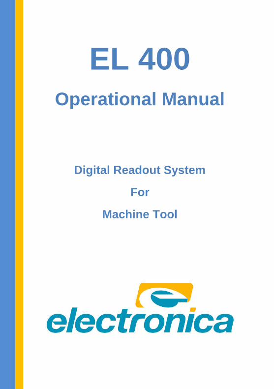
EL 400 Operational Manual
Digital Readout System
For
Machine Tool
EL 400 DRO
2 | P a g e
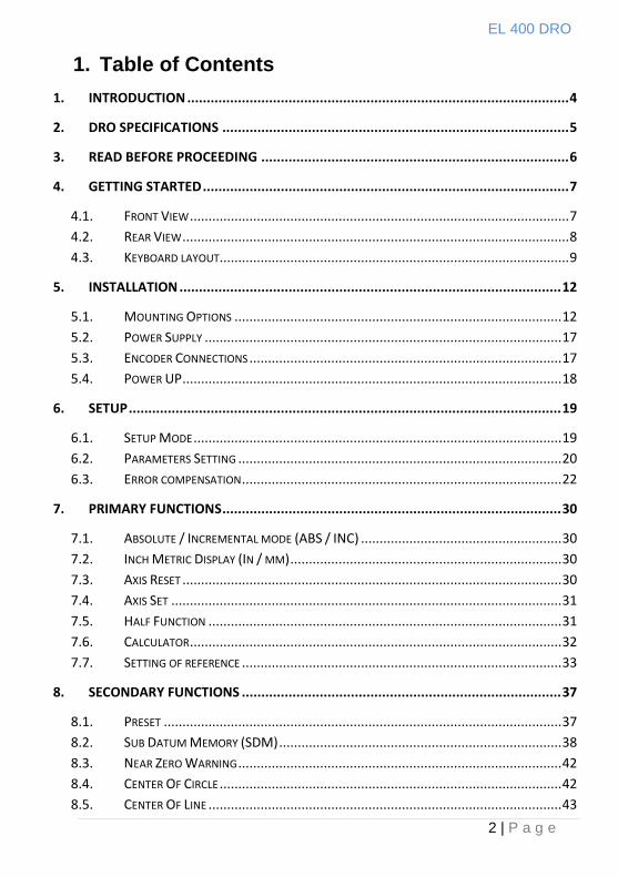
1. Table of Contents
1. INTRODUCTION .................................................................................................. 4
2. DRO SPECIFICATIONS ......................................................................................... 5
3. READ BEFORE PROCEEDING ............................................................................... 6
4. GETTING STARTED .............................................................................................. 7
4.1. FRONT VIEW ...................................................................................................... 7
4.2. REAR VIEW ........................................................................................................ 8
4.3. KEYBOARD LAYOUT .............................................................................................. 9
5. INSTALLATION .................................................................................................. 12
5.1. MOUNTING OPTIONS ........................................................................................ 12
5.2. POWER SUPPLY ................................................................................................ 17
5.3. ENCODER CONNECTIONS .................................................................................... 17
5.4. POWER UP ...................................................................................................... 18
6. SETUP ............................................................................................................... 19
6.1. SETUP MODE ................................................................................................... 19
6.2. PARAMETERS SETTING ....................................................................................... 20
6.3. ERROR COMPENSATION ...................................................................................... 22
7. PRIMARY FUNCTIONS ....................................................................................... 30
7.1. ABSOLUTE / INCREMENTAL MODE (ABS / INC) ...................................................... 30
7.2. INCH METRIC DISPLAY (IN / MM) ......................................................................... 30
7.3. AXIS RESET ...................................................................................................... 30
7.4. AXIS SET ......................................................................................................... 31
7.5. HALF FUNCTION ............................................................................................... 31
7.6. CALCULATOR .................................................................................................... 32
7.7. SETTING OF REFERENCE ...................................................................................... 33
8. SECONDARY FUNCTIONS .................................................................................. 37
8.1. PRESET ........................................................................................................... 37
8.2. SUB DATUM MEMORY (SDM) ............................................................................ 38
8.3. NEAR ZERO WARNING ....................................................................................... 42
8.4. CENTER OF CIRCLE ............................................................................................ 42
8.5. CENTER OF LINE ............................................................................................... 43
EL 400 DRO
3 | P a g e
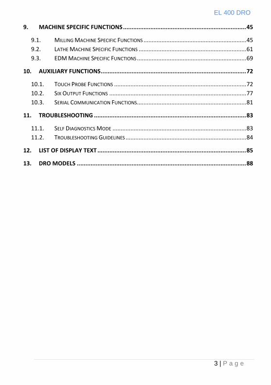
9. MACHINE SPECIFIC FUNCTIONS ........................................................................ 45
9.1. MILLING MACHINE SPECIFIC FUNCTIONS ............................................................... 45
9.2. LATHE MACHINE SPECIFIC FUNCTIONS .................................................................. 61
9.3. EDM MACHINE SPECIFIC FUNCTIONS ................................................................... 69
10. AUXILIARY FUNCTIONS ..................................................................................... 72
10.1. TOUCH PROBE FUNCTIONS ................................................................................. 72
10.2. SIX OUTPUT FUNCTIONS .................................................................................... 77
10.3. SERIAL COMMUNICATION FUNCTIONS ................................................................... 81
11. TROUBLESHOOTING ......................................................................................... 83
11.1. SELF DIAGNOSTICS MODE .................................................................................. 83
11.2. TROUBLESHOOTING GUIDELINES .......................................................................... 84
12. LIST OF DISPLAY TEXT ....................................................................................... 85
13. DRO MODELS ................................................................................................... 88
EL 400 DRO
4 | P a g e
1. Introduction
Congratulations on purchasing EL 400 series Digital Readout
System (DRO) from Electronica Mechatronic Systems. Our DRO
incorporates the latest state of the art technology; giving you world
class features which help in improving productivity, reducing
rejection and at the same time giving ease of operation to user
with its ergonomic design.
Some of the key features of EL 400 series DRO are:
Adaptability to various types of machines, old and new,
simple and complex.
Ease of installation.
Optional fourth axis gives addition encoder combination
possibilities for milling machines.
User friendly operations.
Note: Please familiarize yourself with the contents
of this Operators manual to benefit from all
features provided by EL 400 DRO.
Electronica Mechatronic Systems (I) Pvt. Ltd.
Reserves the right to change specifications
without prior notice.
EL 400 DRO
5 | P a g e
2. DRO Specifications
Mains Supply 90…..265 VAC
50/60 Hz
Fuse Rating 800mA Slow Blow 20mm
Power Consumption 20 Watts Maximum
Storage Temperature -20ºc to 70ºc
Operating Temperature 0ºc to 50ºc
Relative Humidity 20% To 85% Non-Condensing
Dimensions (mm) (*excluding earth stud)
155 X 270 X 80 Height X Width X *Depth
Net Weight Approx 1.5 Kg
Encoder Input RS422
Encoder Connector Type 9-Pin D-Type Female
Auxiliary Connectors
15-Pin D-Type Female For Auxiliary Output (Optional)
Encoder Jack Plug connector for Probe input(Optional) USB B type connector
(for service only)
Encoder Resolution Supported 0.1/0.2/0.5/1/2/5/10/20/50 Micron
Display 7 Digits with +/- indicator
7 Segment LED
Quantization Error +/- 1 Digit
Standard Compliance EMC and Low Voltage
Compliance BS EN 61326 RoHS
ISO 9001:2008 COMPANY
EL 400 DRO
6 | P a g e
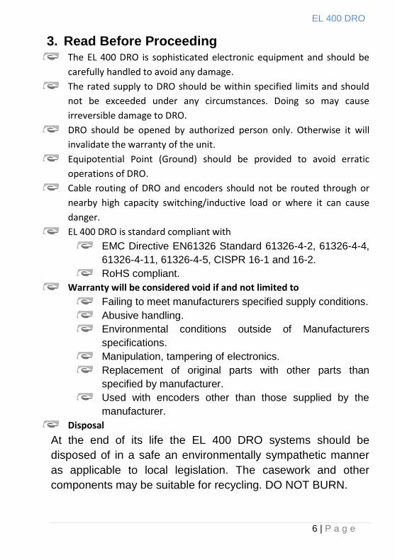
3. Read Before Proceeding The EL 400 DRO is sophisticated electronic equipment and should be
carefully handled to avoid any damage.
The rated supply to DRO should be within specified limits and should
not be exceeded under any circumstances. Doing so may cause
irreversible damage to DRO.
DRO should be opened by authorized person only. Otherwise it will
invalidate the warranty of the unit.
Equipotential Point (Ground) should be provided to avoid erratic
operations of DRO.
Cable routing of DRO and encoders should not be routed through or
nearby high capacity switching/inductive load or where it can cause
danger.
EL 400 DRO is standard compliant with
EMC Directive EN61326 Standard 61326-4-2, 61326-4-4,
61326-4-11, 61326-4-5, CISPR 16-1 and 16-2.
RoHS compliant.
Warranty will be considered void if and not limited to
Failing to meet manufacturers specified supply conditions.
Abusive handling.
Environmental conditions outside of Manufacturers
specifications.
Manipulation, tampering of electronics.
Replacement of original parts with other parts than
specified by manufacturer.
Used with encoders other than those supplied by the
manufacturer.
Disposal
At the end of its life the EL 400 DRO systems should be
disposed of in a safe an environmentally sympathetic manner
as applicable to local legislation. The casework and other
components may be suitable for recycling. DO NOT BURN.
EL 400 DRO
7 | P a g e
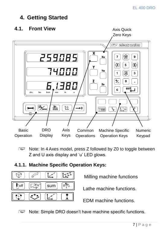
4. Getting Started
4.1. Front View
Note: In 4 Axes model, press Z followed by Z0 to toggle between
Z and U axis display and „u‟ LED glows.
4.1.1. Machine Specific Operation Keys:
Milling machine functions
Lathe machine functions.
EDM machine functions.
Note: Simple DRO doesn‟t have machine specific functions.
Basic
Operation
s
DRO
Display
Axis
Keys
Common
Operations
Machine Specific
Operation Keys
Numeric
Keypad
Axis Quick
Zero Keys
EL 400 DRO
8 | P a g e
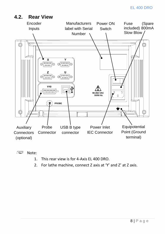
4.2. Rear View
Encoder
Inputs
Auxiliary
Connectors
(optional)
Manufacturers
label with Serial
Number
Power Inlet
IEC Connector
Equipotential
Point (Ground
terminal)
Power ON
Switch
Fuse (Spare included) 800mA Slow Blow 20mm
Probe
Connector
Equipotential
Point (Ground
terminal)
USB B type
connector
Note:
1. This rear view is for 4-Axis EL 400 DRO.
2. For lathe machine, connect Z axis at ‘Y’ and Z’ at Z axis.
EL 400 DRO
9 | P a g e
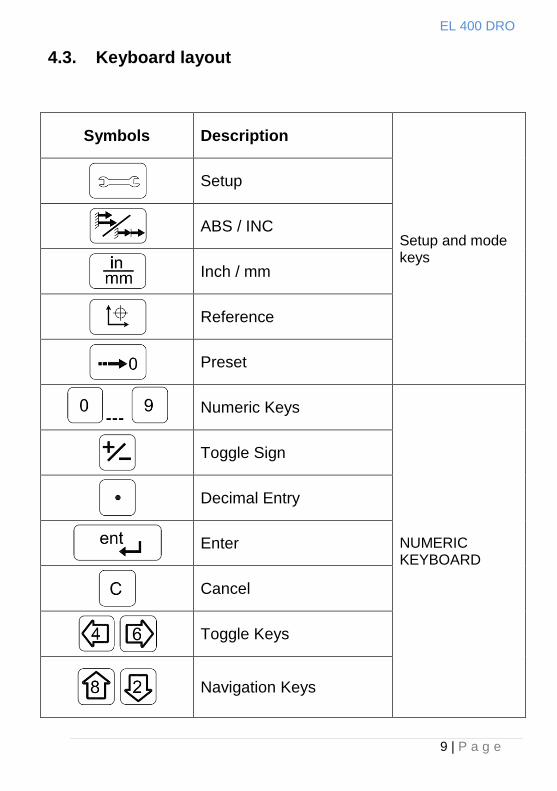
4.3. Keyboard layout
Symbols Description
Setup and mode keys
Setup
ABS / INC
Inch / mm
Reference
Preset
--- Numeric Keys
NUMERIC KEYBOARD
Toggle Sign
Decimal Entry
Enter
Cancel
Toggle Keys
Navigation Keys
EL 400 DRO
10 | P a g e
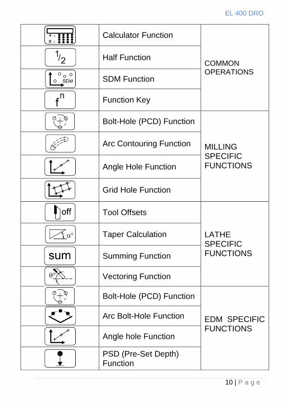
Calculator Function
COMMON OPERATIONS
Half Function
SDM Function
Function Key
Bolt-Hole (PCD) Function
MILLING SPECIFIC FUNCTIONS
Arc Contouring Function
Angle Hole Function
Grid Hole Function
Tool Offsets
LATHE SPECIFIC FUNCTIONS
Taper Calculation
Summing Function
Vectoring Function
Bolt-Hole (PCD) Function
EDM SPECIFIC FUNCTIONS
Arc Bolt-Hole Function
Angle hole Function
PSD (Pre-Set Depth) Function
EL 400 DRO
11 | P a g e
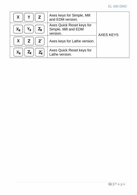
Axes keys for Simple, Mill and EDM version.
AXES KEYS
Axes Quick Reset keys for Simple, Mill and EDM version.
Axes keys for Lathe version.
Axes Quick Reset keys for Lathe version.
EL 400 DRO
12 | P a g e
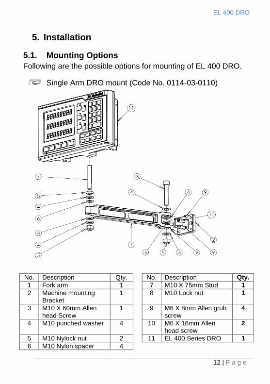
5. Installation
5.1. Mounting Options
Following are the possible options for mounting of EL 400 DRO.
Single Arm DRO mount (Code No. 0114-03-0110)
No. Description Qty. No. Description Qty.
1 Fork arm 1 7 M10 X 75mm Stud 1
2 Machine mounting Bracket
1 8 M10 Lock nut 1
3 M10 X 60mm Allen head Screw
1 9 M6 X 8mm Allen grub screw
4
4 M10 punched washer 4 10 M6 X 16mm Allen head screw
2
5 M10 Nylock nut 2 11 EL 400 Series DRO 1
6 M10 Nylon spacer 4
EL 400 DRO
13 | P a g e
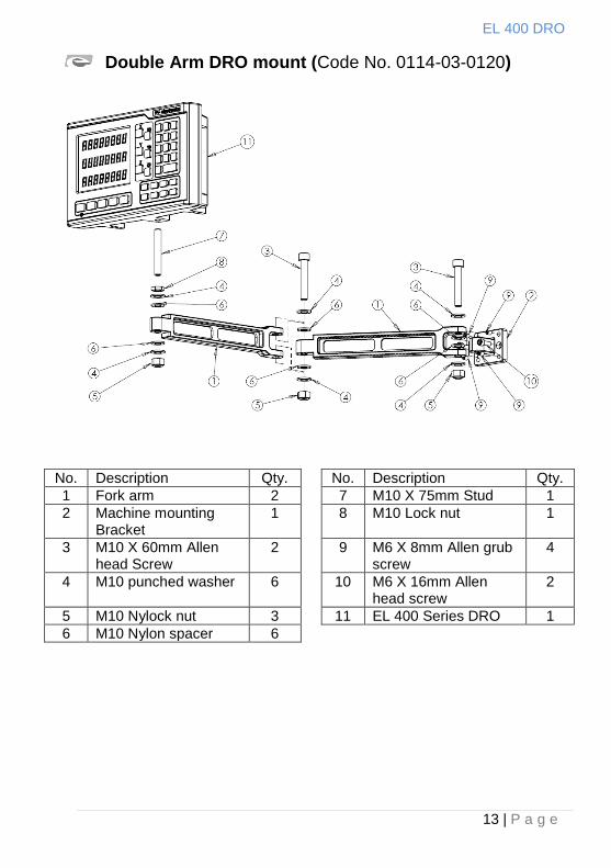
Double Arm DRO mount (Code No. 0114-03-0120)
No. Description Qty. No. Description Qty.
1 Fork arm 2 7 M10 X 75mm Stud 1
2 Machine mounting Bracket
1 8 M10 Lock nut 1
3 M10 X 60mm Allen head Screw
2 9 M6 X 8mm Allen grub screw
4
4 M10 punched washer 6 10 M6 X 16mm Allen head screw
2
5 M10 Nylock nut 3 11 EL 400 Series DRO 1
6 M10 Nylon spacer 6
EL 400 DRO
14 | P a g e
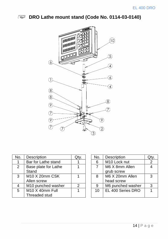
DRO Lathe mount stand (Code No. 0114-03-0140)
No. Description Qty. No. Description Qty.
1 Bar for Lathe stand 1 6 M10 Lock nut 2
2 Base plate for Lathe Stand
1 7 M6 X 8mm Allen grub screw
4
3 M10 X 20mm CSK Allen screw
1 8 M6 X 20mm Allen head screw
3
4 M10 punched washer 2 9 M6 punched washer 3
5 M10 X 40mm Full Threaded stud
1 10 EL 400 Series DRO 1
EL 400 DRO
15 | P a g e
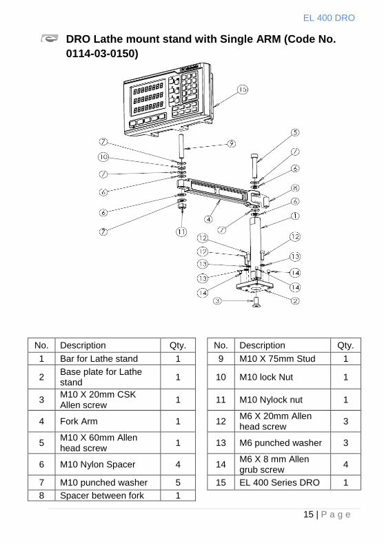
DRO Lathe mount stand with Single ARM (Code No.
0114-03-0150)
No. Description Qty. No. Description Qty.
1 Bar for Lathe stand 1 9 M10 X 75mm Stud 1
2 Base plate for Lathe stand
1 10 M10 lock Nut 1
3 M10 X 20mm CSK Allen screw
1 11 M10 Nylock nut 1
4 Fork Arm 1 12 M6 X 20mm Allen head screw
3
5 M10 X 60mm Allen head screw
1 13 M6 punched washer 3
6 M10 Nylon Spacer 4 14 M6 X 8 mm Allen grub screw
4
7 M10 punched washer 5 15 EL 400 Series DRO 1
8 Spacer between fork 1
EL 400 DRO
16 | P a g e
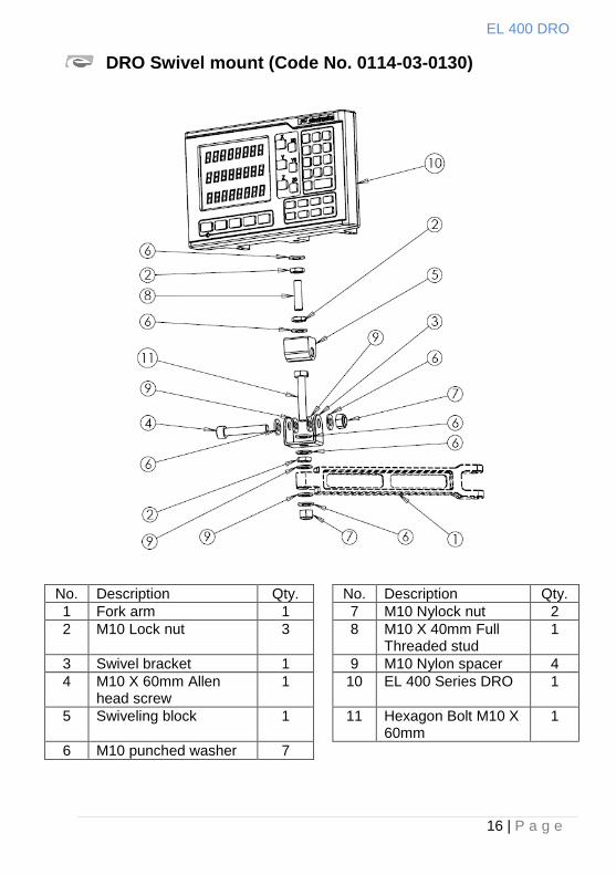
DRO Swivel mount (Code No. 0114-03-0130)
No. Description Qty. No. Description Qty.
1 Fork arm 1 7 M10 Nylock nut 2
2 M10 Lock nut 3 8 M10 X 40mm Full Threaded stud
1
3 Swivel bracket 1 9 M10 Nylon spacer 4
4 M10 X 60mm Allen head screw
1 10 EL 400 Series DRO 1
5 Swiveling block 1 11 Hexagon Bolt M10 X 60mm
1
6 M10 punched washer 7
EL 400 DRO
17 | P a g e
5.2. Power Supply
The EL 400 DRO series uses a Switch mode power supply inside
which covers the universal power input range i.e. 90VAC to
265VAC / 50 to 60 Hz. Ensure the input power is within the
specifications before powering the unit.
The power supply to the DRO should not be given from the same
source as that of any high capacity switching / inductive loads to
avoid interference.
Ensure proper equipotential point (Ground) connection is provided
to the DRO to avoid any erratic operations.
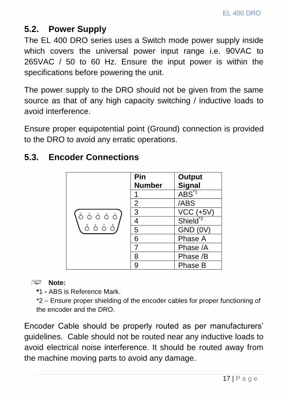
5.3. Encoder Connections
Note:
*1 - ABS is Reference Mark.
*2 – Ensure proper shielding of the encoder cables for proper functioning of
the encoder and the DRO.
Encoder Cable should be properly routed as per manufacturers‟
guidelines. Cable should not be routed near any inductive loads to
avoid electrical noise interference. It should be routed away from
the machine moving parts to avoid any damage.
Pin Number
Output Signal
1 ABS*1
2 /ABS
3 VCC (+5V)
4 Shield*2
5 GND (0V)
6 Phase A
7 Phase /A
8 Phase /B
9 Phase B
EL 400 DRO
18 | P a g e
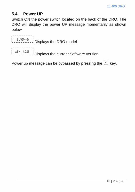
5.4. Power UP
Switch ON the power switch located on the back of the DRO. The
DRO will display the power UP message momentarily as shown
below
Displays the DRO model
Displays the current Software version
Power up message can be bypassed by pressing the key.
..
EL 400 DRO
19 | P a g e
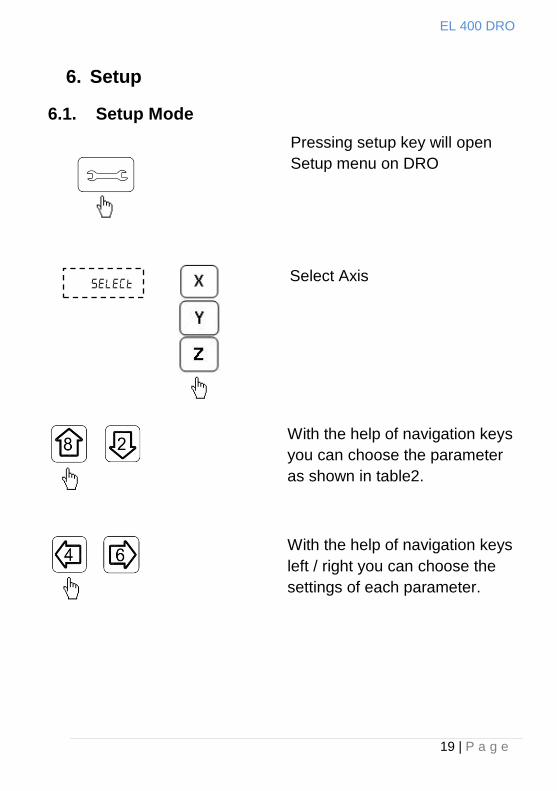
6. Setup
6.1. Setup Mode
With the help of navigation keys
you can choose the parameter
as shown in table2.
With the help of navigation keys
left / right you can choose the
settings of each parameter.
Pressing setup key will open
Setup menu on DRO
Select Axis
EL 400 DRO
20 | P a g e
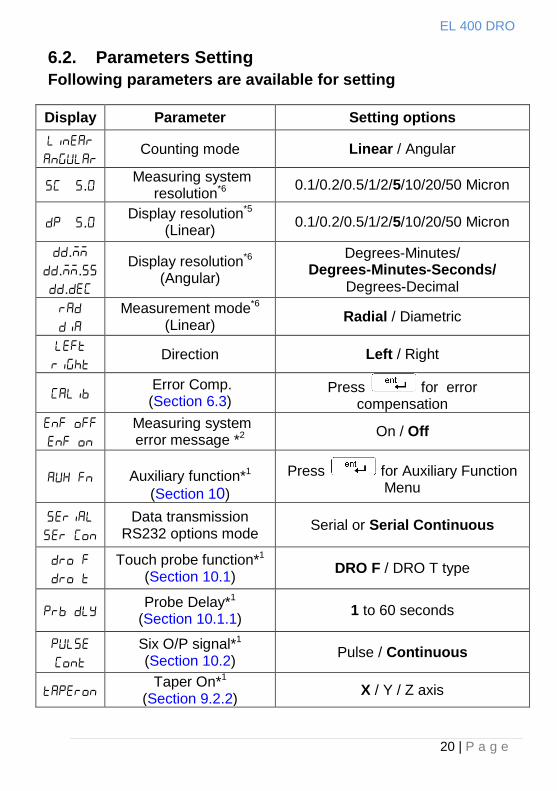
6.2. Parameters Setting
Following parameters are available for setting
Display Parameter Setting options
Counting mode Linear / Angular
. Measuring system
resolution*6 0.1/0.2/0.5/1/2/5/10/20/50 Micron
. Display resolution*5
(Linear) 0.1/0.2/0.5/1/2/5/10/20/50 Micron
.
..
.
Display resolution*6 (Angular)
Degrees-Minutes/ Degrees-Minutes-Seconds/
Degrees-Decimal
Measurement mode*6 (Linear)
Radial / Diametric
Direction Left / Right
Error Comp. (Section 6.3)
Press for error compensation
Measuring system error message *2
On / Off
Auxiliary function*1
(Section 10)
Press for Auxiliary Function Menu
Data transmission RS232 options mode
Serial or Serial Continuous
Touch probe function*1 (Section 10.1)
DRO F / DRO T type
Probe Delay*1
(Section 10.1.1) 1 to 60 seconds
Six O/P signal*1 (Section 10.2)
Pulse / Continuous
Taper On*1
(Section 9.2.2) X / Y / Z axis
EL 400 DRO
21 | P a g e
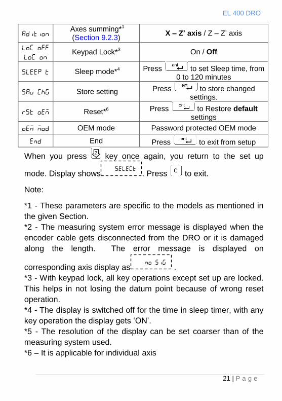
Axes summing*1 (Section 9.2.3)
X – Z’ axis / Z – Z‟ axis
Keypad Lock*3 On / Off
Sleep mode*4 Press to set Sleep time, from 0 to 120 minutes
Store setting Press to store changed settings.
Reset*6 Press to Restore default settings
OEM mode Password protected OEM mode
End Press to exit from setup
When you press key once again, you return to the set up
mode. Display shows . Press to exit.
Note:
*1 - These parameters are specific to the models as mentioned in
the given Section.
*2 - The measuring system error message is displayed when the
encoder cable gets disconnected from the DRO or it is damaged
along the length. The error message is displayed on
corresponding axis display as .
*3 - With keypad lock, all key operations except set up are locked.
This helps in not losing the datum point because of wrong reset
operation.
*4 - The display is switched off for the time in sleep timer, with any
key operation the display gets „ON‟.
*5 - The resolution of the display can be set coarser than of the
measuring system used.
*6 – It is applicable for individual axis
EL 400 DRO
22 | P a g e
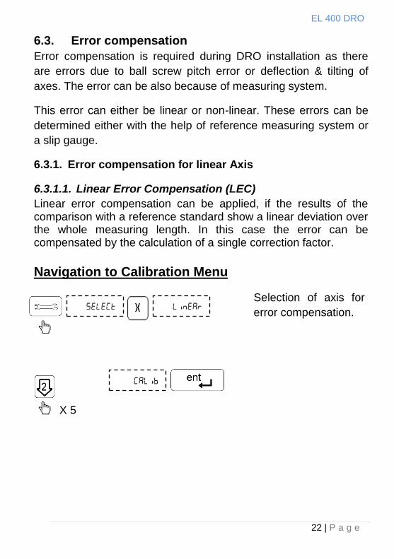
6.3. Error compensation
Error compensation is required during DRO installation as there
are errors due to ball screw pitch error or deflection & tilting of
axes. The error can be also because of measuring system.
This error can either be linear or non-linear. These errors can be
determined either with the help of reference measuring system or
a slip gauge.
6.3.1. Error compensation for linear Axis
6.3.1.1. Linear Error Compensation (LEC)
Linear error compensation can be applied, if the results of the comparison with a reference standard show a linear deviation over the whole measuring length. In this case the error can be compensated by the calculation of a single correction factor. Navigation to Calibration Menu
Selection of axis for
error compensation.
X 5
EL 400 DRO
23 | P a g e
Linear Error Compensation
Select Linear Error
Compensation (LEC)
menu.
. Press Enter for display
value menu.
Move the axis away from
datum point to put the slip
gauge at datum point.
Move the axis to touch the
slip gauge. The display value
is the measured length of the
slip gauge
Set the machine at datum
point (starting point) and
press the axis key to reset
the axis.
.
EL 400 DRO
24 | P a g e
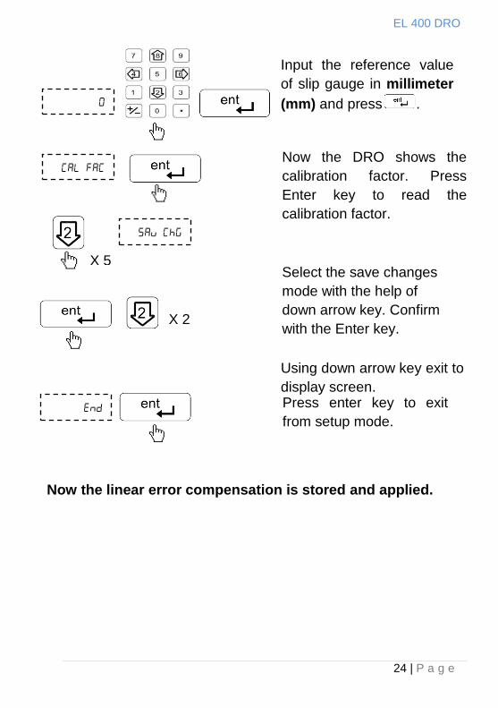
Now the linear error compensation is stored and applied.
Select the save changes
mode with the help of
down arrow key. Confirm
with the Enter key.
Press enter key to exit
from setup mode.
Using down arrow key exit to
display screen.
Now the DRO shows the
calibration factor. Press
Enter key to read the
calibration factor.
Input the reference value
of slip gauge in millimeter
(mm) and press .
X 5
X 2
EL 400 DRO
25 | P a g e
Machine Reference
point
Home Reference
point
Travel
1 2 3 4 5 ERROR
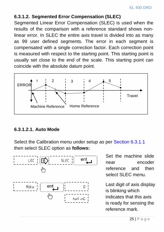
6.3.1.2. Segmented Error Compensation (SLEC)
Segmented Linear Error Compensation (SLEC) is used when the
results of the comparison with a reference standard shows non-
linear error. In SLEC the entire axis travel is divided into as many
as 99 user defined segments. The error in each segment is
compensated with a single correction factor. Each correction point
is measured with respect to the starting point. This starting point is
usually set close to the end of the scale. This starting point can
coincide with the absolute datum point.
6.3.1.2.1. Auto Mode
Select the Calibration menu under setup as per Section 6.3.1.1
then select SLEC option as follows:
Set the machine slide
near encoder
reference and then
select SLEC menu.
Last digit of axis display
is blinking which
indicates that this axis
is ready for sensing the
reference mark.
EL 400 DRO
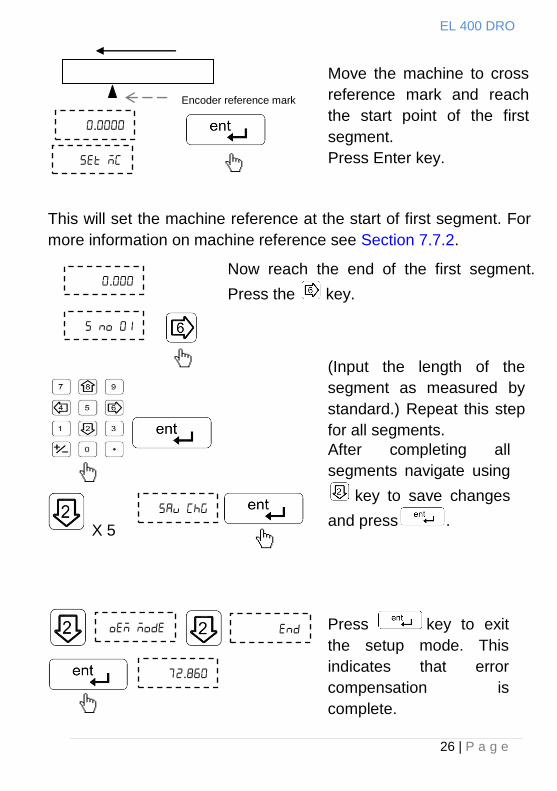
26 | P a g e
After completing all
segments navigate using
key to save changes
and press .
.
This will set the machine reference at the start of first segment. For
more information on machine reference see Section 7.7.2.
Move the machine to cross
reference mark and reach
the start point of the first
segment.
Press Enter key.
Encoder reference mark
.
Now reach the end of the first segment.
Press the key.
.
(Input the length of the
segment as measured by
standard.) Repeat this step
for all segments.
Press key to exit
the setup mode. This
indicates that error
compensation is
complete.
X 5
EL 400 DRO
27 | P a g e
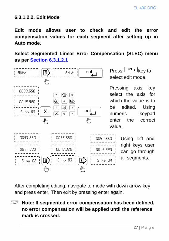
6.3.1.2.2. Edit Mode
Edit mode allows user to check and edit the error
compensation values for each segment after setting up in
Auto mode.
Select Segmented Linear Error Compensation (SLEC) menu
as per Section 6.3.1.2.1
After completing editing, navigate to mode with down arrow key
and press enter. Then exit by pressing enter again.
Note: If segmented error compensation has been defined,
no error compensation will be applied until the reference
mark is crossed.
.
.
Press key to
select edit mode.
Pressing axis key
select the axis for
which the value is to
be edited. Using
numeric keypad
enter the correct
value.
.
.
.
.
.
.
Using left and
right keys user
can go through
all segments.
EL 400 DRO
28 | P a g e
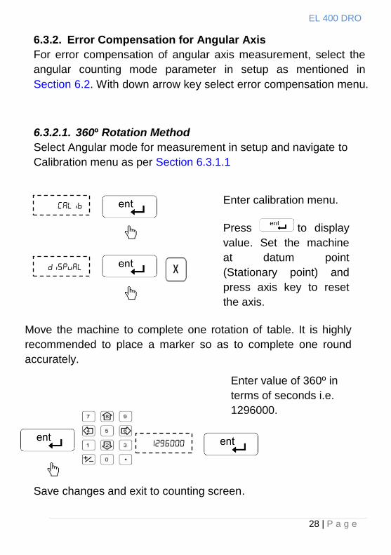
6.3.2. Error Compensation for Angular Axis
For error compensation of angular axis measurement, select the
angular counting mode parameter in setup as mentioned in
Section 6.2. With down arrow key select error compensation menu.
6.3.2.1. 360º Rotation Method
Select Angular mode for measurement in setup and navigate to
Calibration menu as per Section 6.3.1.1
Save changes and exit to counting screen.
Enter calibration menu.
Press to display
value. Set the machine
at datum point
(Stationary point) and
press axis key to reset
the axis.
Move the machine to complete one rotation of table. It is highly
recommended to place a marker so as to complete one round
accurately.
Enter value of 360º in
terms of seconds i.e.
1296000.
EL 400 DRO
29 | P a g e
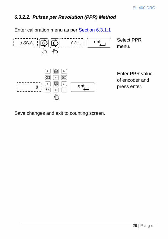
6.3.2.2. Pulses per Revolution (PPR) Method
Enter calibration menu as per Section 6.3.1.1
Save changes and exit to counting screen.
...
Enter PPR value
of encoder and
press enter.
Select PPR
menu.
EL 400 DRO
30 | P a g e
7. Primary functions
7.1. Absolute / Incremental mode (ABS / INC)
The key toggles between the Absolute / Incremental position
display.
Absolute mode displays the positions of all axes from a fixed
datum.
The Incremental mode displays each position relative to the last
position. This is also known as point to point use.
The LED indicates the current selection of mode.
Note: At the beginning of each working session, set the datum in Absolute Mode, and then switch the DRO to Incremental Mode. By using the DRO in this way, you can return the machine to its absolute datum at any time, simply by switching back to Absolute Mode.
7.2. Inch Metric Display (In / mm)
The key toggles between the Inch units (in) or the millimeter
units (mm).
The LEDs indicate the current mode of display.
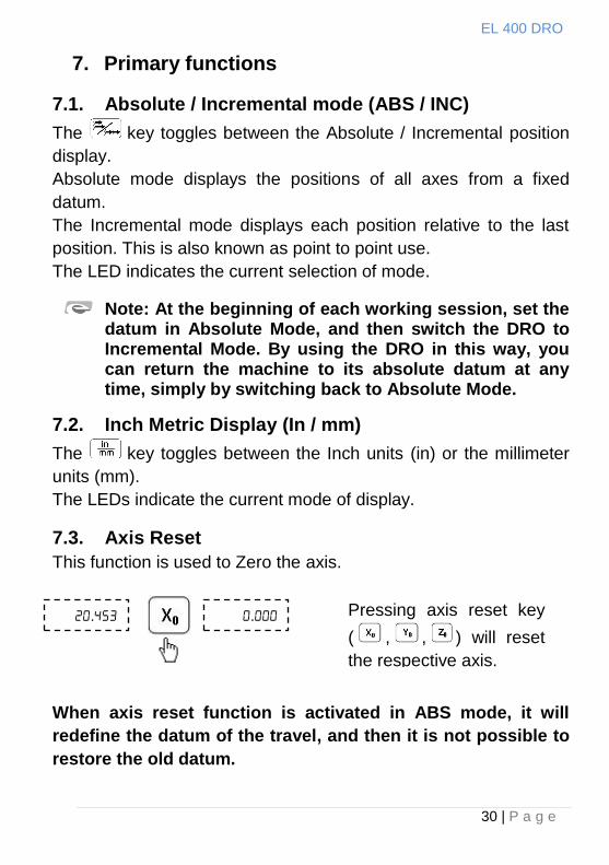
7.3. Axis Reset
This function is used to Zero the axis.
When axis reset function is activated in ABS mode, it will
redefine the datum of the travel, and then it is not possible to
restore the old datum.
. . Pressing axis reset key
( , , ) will reset
the respective axis.
EL 400 DRO
31 | P a g e
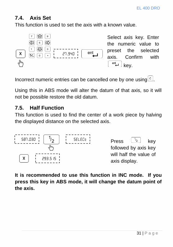
7.4. Axis Set
This function is used to set the axis with a known value.
Incorrect numeric entries can be cancelled one by one using .
Using this in ABS mode will alter the datum of that axis, so it will
not be possible restore the old datum.
7.5. Half Function
This function is used to find the center of a work piece by halving
the displayed distance on the selected axis.
It is recommended to use this function in INC mode. If you
press this key in ABS mode, it will change the datum point of
the axis.
.
Select axis key. Enter
the numeric value to
preset the selected
axis. Confirm with
key.
Press key
followed by axis key
will half the value of
axis display.
.
.
EL 400 DRO
32 | P a g e
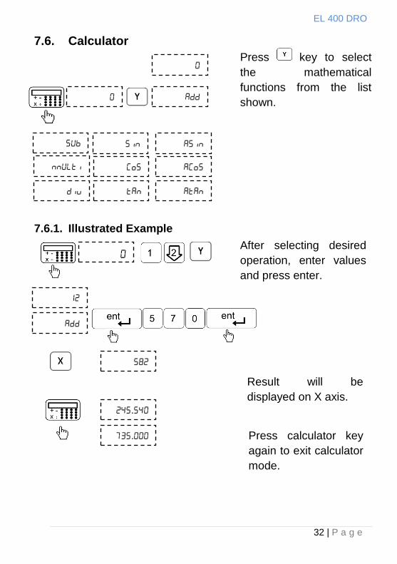
7.6. Calculator
7.6.1. Illustrated Example
Press key to select
the mathematical
functions from the list
shown.
After selecting desired
operation, enter values
and press enter.
Result will be
displayed on X axis.
.
. Press calculator key
again to exit calculator
mode.
EL 400 DRO
33 | P a g e
7.7. Setting of reference
This function allows user to set a machine zero point. With this
machine zero point users can restore the work coordinates even if
the machine is moved when the DRO is in OFF condition.
Generally each encoder has reference marks present at every
specified interval. These reference marks are used to recall the
same datum point every time.
This function works only in ABS mode. If tried to use in INC mode,
the DRO is automatically forced to ABS mode and then the
function executes.
There are two Positions which can be set as datum point (Home
function)
Reference point of measuring system.
Machine reference mark.
EL 400 DRO
34 | P a g e
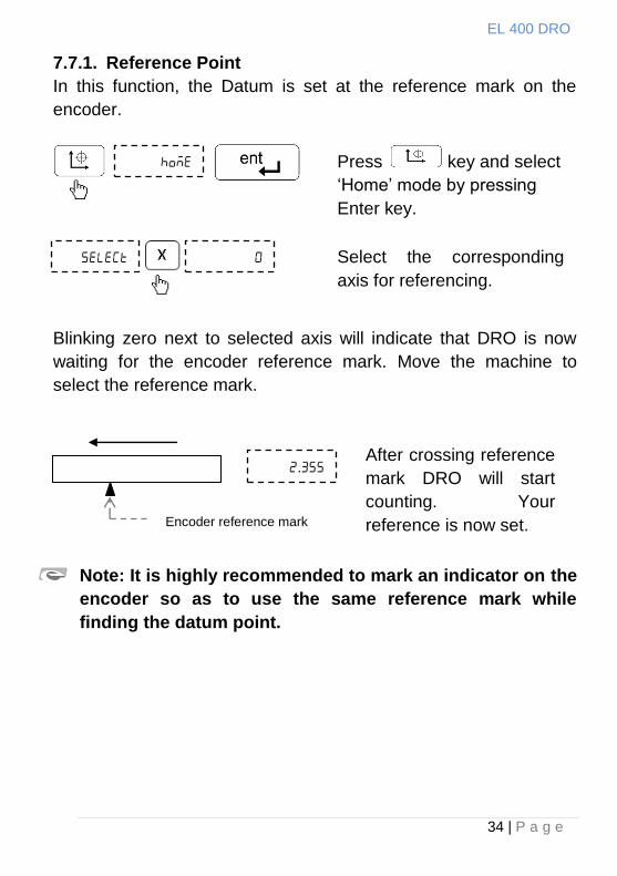
7.7.1. Reference Point
In this function, the Datum is set at the reference mark on the
encoder.
Blinking zero next to selected axis will indicate that DRO is now
waiting for the encoder reference mark. Move the machine to
select the reference mark.
Note: It is highly recommended to mark an indicator on the
encoder so as to use the same reference mark while
finding the datum point.
Press key and select
„Home‟ mode by pressing
Enter key.
Select the corresponding
axis for referencing.
After crossing reference
mark DRO will start
counting. Your
reference is now set.
.
Encoder reference mark
EL 400 DRO
35 | P a g e
7.7.2. Machine Reference function
Machine referencing is used when datum is not at the reference
mark on encoder but at a fixed distance from reference mark.
7.7.2.1. Setting of Machine Reference
Before setting the machine reference, make sure to perform
reference point function as discussed in Section 7.7.1
Note: In machine reference function, the absolutes datum
is at a fixed distance from the reference mark of an
encoder. It is marked permanently on the machine
.
Move the machine to
the required machine
reference position.
Then navigate with
left/right arrow key to
Set Machine Reference
menu and press Enter
to confirm the position.
. Now display will show
zero on selected axis.
This indicates that
selected point is set as
machine reference for
that axis.
Select the axis for which machine reference is to be set.
EL 400 DRO
36 | P a g e
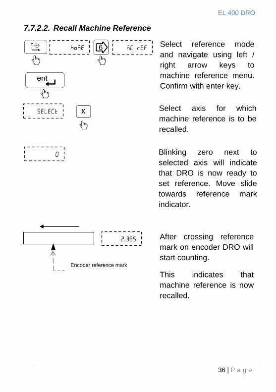
7.7.2.2. Recall Machine Reference
Select reference mode
and navigate using left /
right arrow keys to
machine reference menu.
Confirm with enter key.
Select axis for which
machine reference is to be
recalled.
After crossing reference
mark on encoder DRO will
start counting.
This indicates that
machine reference is now
recalled.
Encoder reference mark
.
Blinking zero next to
selected axis will indicate
that DRO is now ready to
set reference. Move slide
towards reference mark
indicator.
EL 400 DRO
37 | P a g e
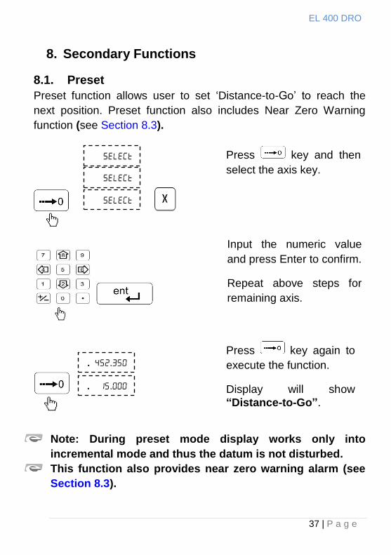
8. Secondary Functions
8.1. Preset
Preset function allows user to set „Distance-to-Go‟ to reach the
next position. Preset function also includes Near Zero Warning
function (see Section 8.3).
Note: During preset mode display works only into
incremental mode and thus the datum is not disturbed.
This function also provides near zero warning alarm (see
Section 8.3).
Press key and then
select the axis key.
. .
. .
Press key again to
execute the function.
Display will show
“Distance-to-Go”.
Input the numeric value
and press Enter to confirm.
Repeat above steps for
remaining axis.
EL 400 DRO
38 | P a g e
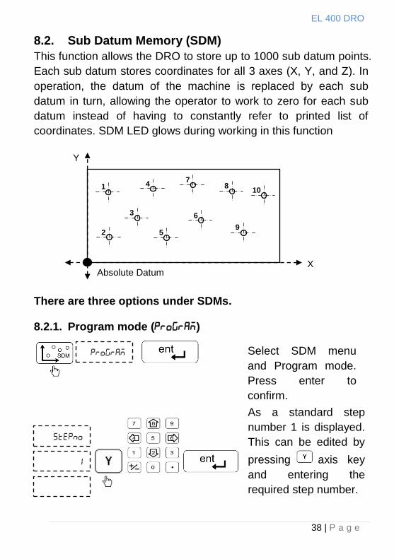
8.2. Sub Datum Memory (SDM)
This function allows the DRO to store up to 1000 sub datum points.
Each sub datum stores coordinates for all 3 axes (X, Y, and Z). In
operation, the datum of the machine is replaced by each sub
datum in turn, allowing the operator to work to zero for each sub
datum instead of having to constantly refer to printed list of
coordinates. SDM LED glows during working in this function
There are three options under SDMs.
8.2.1. Program mode ()
Select SDM menu
and Program mode.
Press enter to
confirm.
As a standard step
number 1 is displayed.
This can be edited by
pressing axis key
and entering the
required step number.
Absolute Datum X
Y
1
2
3
4
5
7 8
9
10
6

EL 400 DRO
39 | P a g e
In this manner, you can enter all SDMs.
Press key to exit.
.
.
Select the required axis
and enter the values for
the selected step. Press
to confirm each
value.
.
Press key to go to
next step. With right and
left key user can select
previous/next step. To
go any step directly after
pressing press
key and then step
number which user want
to go and press
key.
Press to see current step number Press Up arrow key again to exit.
EL 400 DRO
40 | P a g e
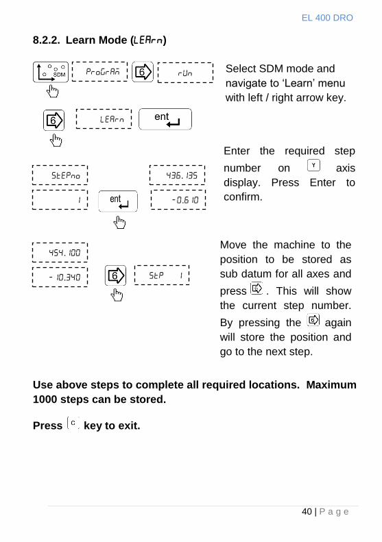
8.2.2. Learn Mode ()
Use above steps to complete all required locations. Maximum
1000 steps can be stored.
Press key to exit.
Select SDM mode and
navigate to „Learn‟ menu
with left / right arrow key.
Enter the required step
number on axis
display. Press Enter to
confirm.
.
.
.
.
Move the machine to the
position to be stored as
sub datum for all axes and
press . This will show
the current step number.
By pressing the again
will store the position and
go to the next step.
EL 400 DRO
41 | P a g e
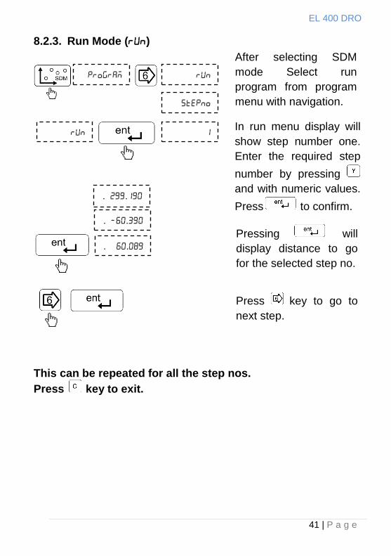
8.2.3. Run Mode ()
This can be repeated for all the step nos.
Press key to exit.
. .
. .
After selecting SDM
mode Select run
program from program
menu with navigation.
In run menu display will
show step number one.
Enter the required step
number by pressing
and with numeric values.
Press to confirm.
Press key to go to
next step.
. .
Pressing will
display distance to go
for the selected step no.
EL 400 DRO
42 | P a g e
8.3. Near Zero Warning
EL 400 DRO features a unique Near Zero Warning function which
alerts user once the machine position is within 50 microns of the
set value.
This function is automatically enabled in the following functions:
Preset function
Sub Datum Memory (SDM)
All milling specific functions.
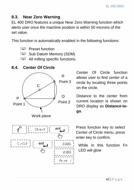
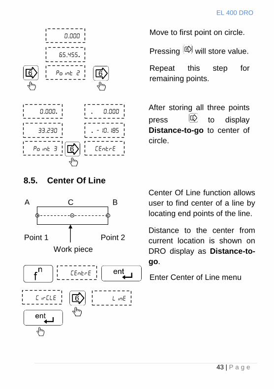
8.4. Center Of Circle
R
Point 3
Point 2 Point 1
P Q
Work piece
C
Center Of Circle function
allows user to find center of a
circle by locating three points
on the circle.
Distance to the center from
current location is shown on
DRO display as Distance-to-
go.
Press function key to select
Center of Circle menu, press
enter key to confirm.
..
.
While in this function Fn
LED will glow
EL 400 DRO
43 | P a g e
8.5. Center Of Line
.
..
Move to first point on circle.
Pressing will store value.
Repeat this step for
remaining points.
..
.
. .
. .
After storing all three points
press to display
Distance-to-go to center of
circle.
Center Of Line function allows
user to find center of a line by
locating end points of the line.
Distance to the center from
current location is shown on
DRO display as Distance-to-
go.
Enter Center of Line menu
C A B
Point 1 Point 2
Work piece
EL 400 DRO
44 | P a g e
..
.
.
..
Move to first point on line.
Pressing will store value.
Repeat this step for second
point.
. .
. .
After storing both points
pressing will display
Distance-to-go to center of
line.
EL 400 DRO
45 | P a g e
Radius
Start
Point Arc
Center
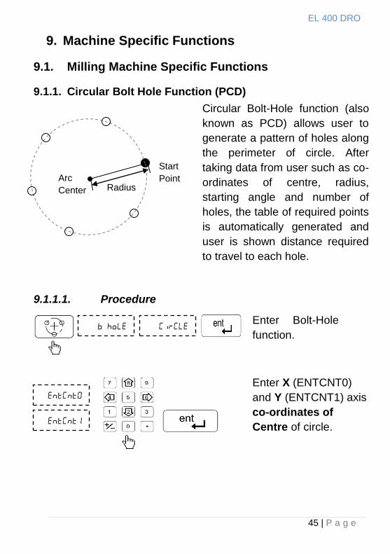
9. Machine Specific Functions
9.1. Milling Machine Specific Functions
9.1.1. Circular Bolt Hole Function (PCD)
9.1.1.1. Procedure
Enter Bolt-Hole
function.
Enter X (ENTCNT0)
and Y (ENTCNT1) axis
co-ordinates of
Centre of circle.
Circular Bolt-Hole function (also
known as PCD) allows user to
generate a pattern of holes along
the perimeter of circle. After
taking data from user such as co-
ordinates of centre, radius,
starting angle and number of
holes, the table of required points
is automatically generated and
user is shown distance required
to travel to each hole.
EL 400 DRO
46 | P a g e
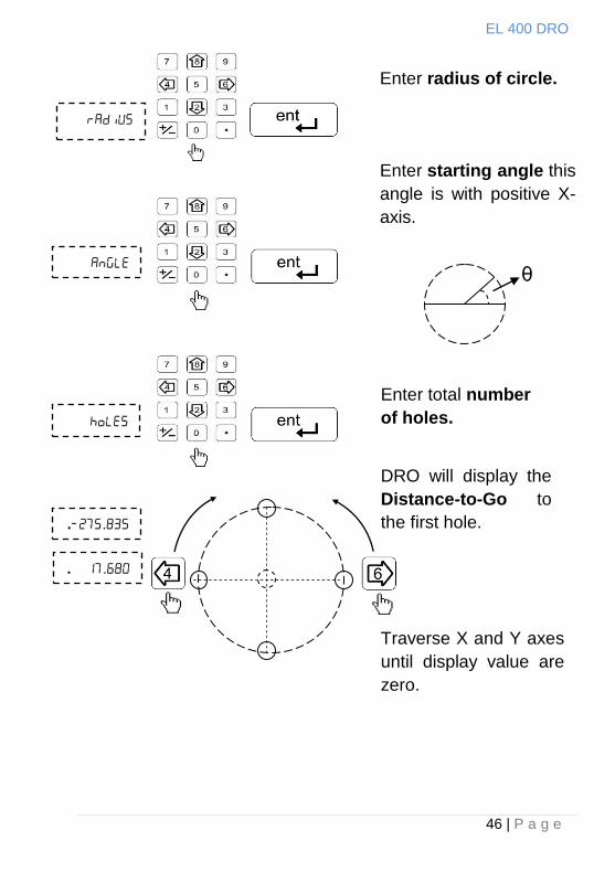
Enter radius of circle.
Enter starting angle this
angle is with positive X-
axis.
θ
Traverse X and Y axes
until display value are
zero.
Enter total number
of holes.
DRO will display the
Distance-to-Go to
the first hole.
..
. .
EL 400 DRO
47 | P a g e
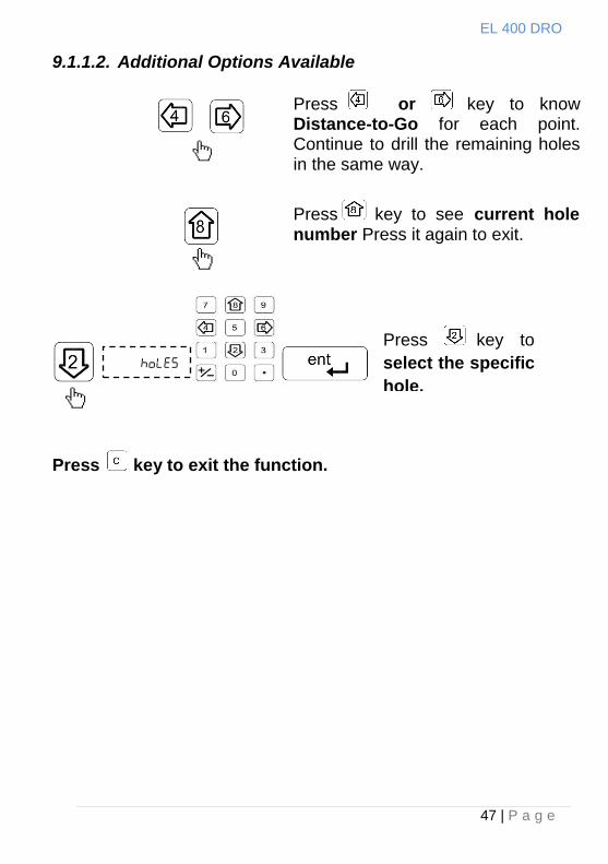
9.1.1.2. Additional Options Available
Press key to exit the function.
Press or key to know Distance-to-Go for each point. Continue to drill the remaining holes in the same way.
Press key to
select the specific
hole.
Press key to see current hole number Press it again to exit.
EL 400 DRO
48 | P a g e
Radius
End
Point
Start
Point Arc
Center
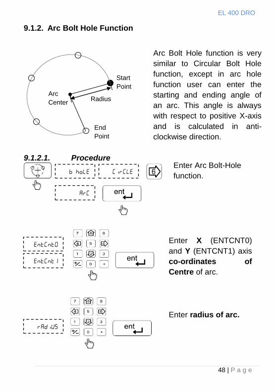
9.1.2. Arc Bolt Hole Function
9.1.2.1. Procedure
Arc Bolt Hole function is very
similar to Circular Bolt Hole
function, except in arc hole
function user can enter the
starting and ending angle of
an arc. This angle is always
with respect to positive X-axis
and is calculated in anti-
clockwise direction.
Enter Arc Bolt-Hole
function.
Enter X (ENTCNT0)
and Y (ENTCNT1) axis
co-ordinates of
Centre of arc.
Enter radius of arc.
EL 400 DRO
49 | P a g e
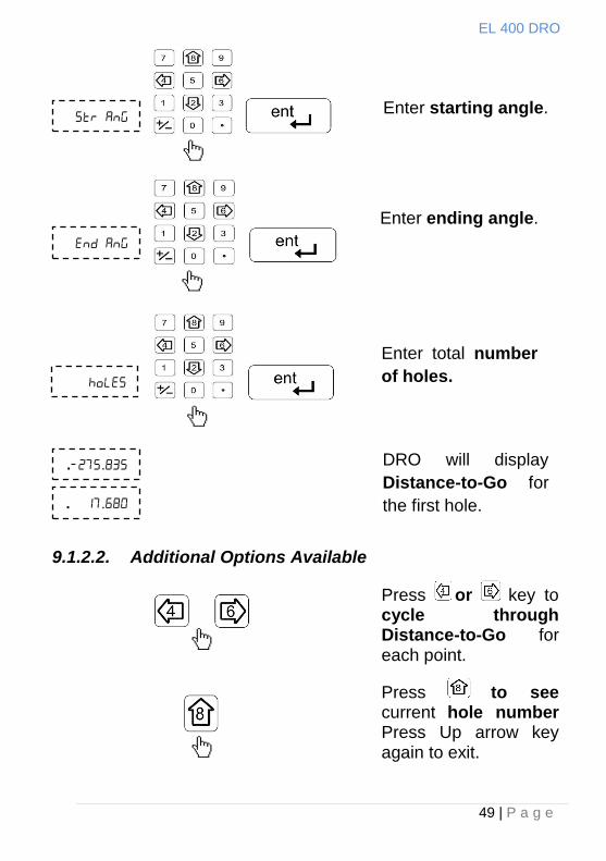
9.1.2.2. Additional Options Available
Enter starting angle.
Enter ending angle.
Enter total number
of holes.
DRO will display
Distance-to-Go for
the first hole.
..
. .
Press or key to cycle through Distance-to-Go for each point.
Press to see current hole number Press Up arrow key again to exit.
EL 400 DRO
50 | P a g e
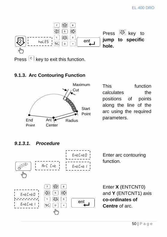
Press key to exit this function.
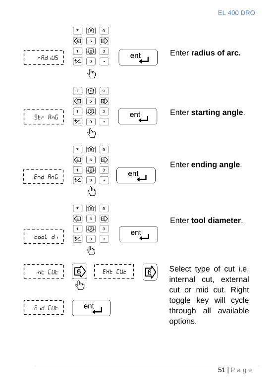
9.1.3. Arc Contouring Function
9.1.3.1. Procedure
Press key to
jump to specific
hole.
This function
calculates the
positions of points
along the line of the
arc using the required
parameters.
Enter arc contouring
function.
Enter X (ENTCNT0)
and Y (ENTCNT1) axis
co-ordinates of
Centre of arc.
Radius End
Point
Start
Point
Arc
Center
Maximum
Cut
EL 400 DRO
51 | P a g e
Enter radius of arc.
Enter starting angle.
Enter ending angle.
Enter tool diameter.
Select type of cut i.e.
internal cut, external
cut or mid cut. Right
toggle key will cycle
through all available
options.
EL 400 DRO
52 | P a g e
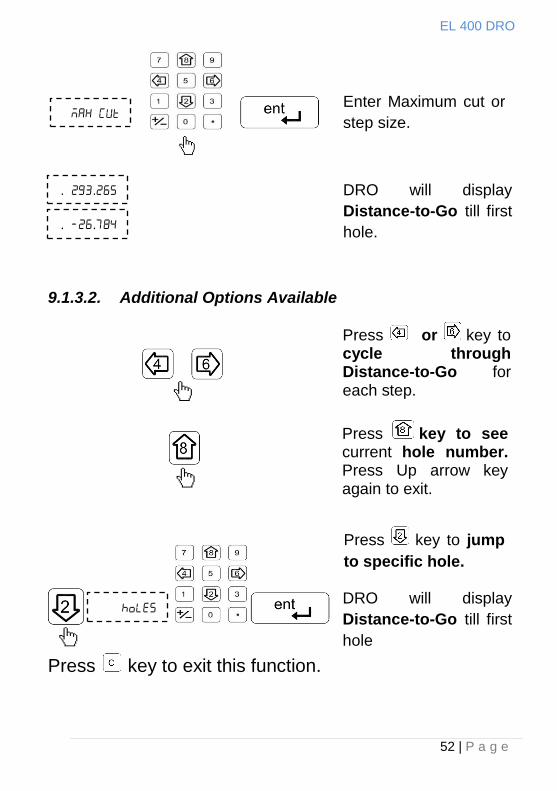
9.1.3.2. Additional Options Available
Press key to exit this function.
. .
. .
Enter Maximum cut or
step size.
DRO will display
Distance-to-Go till first
hole.
DRO will display
Distance-to-Go till first
hole
Press or key to cycle through Distance-to-Go for each step.
Press key to jump
to specific hole.
Press key to see current hole number. Press Up arrow key again to exit.
EL 400 DRO
53 | P a g e
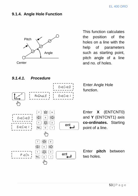
9.1.4. Angle Hole Function
9.1.4.1. Procedure
Enter Angle Hole
function.
Enter X (ENTCNT0)
and Y (ENTCNT1) axis
co-ordinates. Starting
point of a line.
Enter pitch between
two holes.
Pitch
Center
Angle
This function calculates
the position of the
holes on a line with the
help of parameters
such as starting point,
pitch angle of a line
and no. of holes.
EL 400 DRO
54 | P a g e
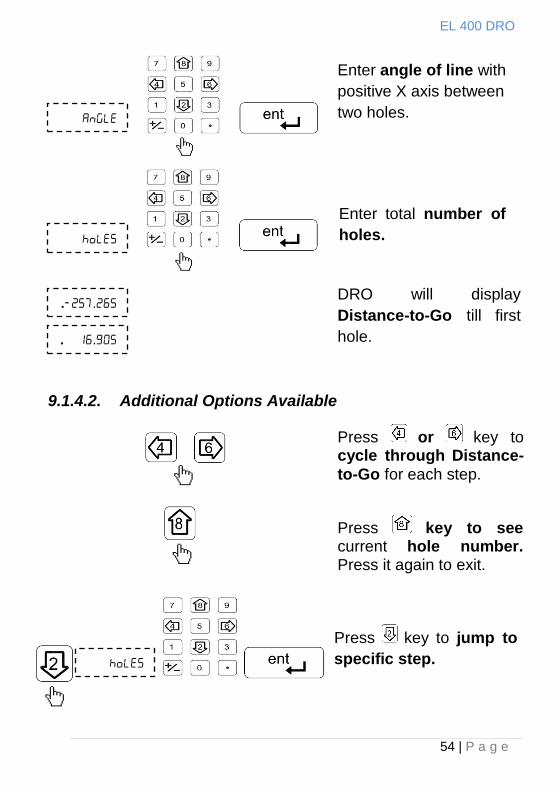
9.1.4.2. Additional Options Available
..
. .
Enter angle of line with
positive X axis between
two holes.
Enter total number of
holes.
DRO will display
Distance-to-Go till first
hole.
Press or key to cycle through Distance-
to-Go for each step.
Press key to jump to
specific step.
Press key to see current hole number. Press it again to exit.
EL 400 DRO
55 | P a g e
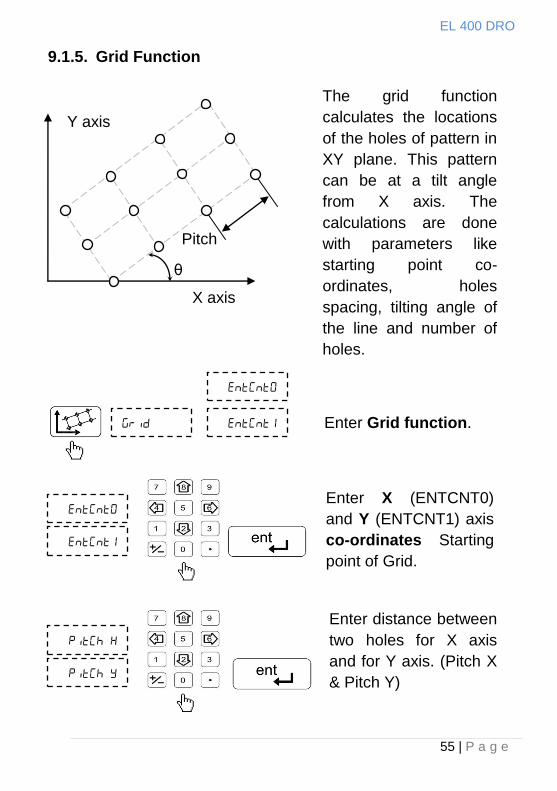
9.1.5. Grid Function
X axis
Y axis
Pitch
θ
Enter Grid function.
Enter X (ENTCNT0)
and Y (ENTCNT1) axis
co-ordinates Starting
point of Grid.
Enter distance between
two holes for X axis
and for Y axis. (Pitch X
& Pitch Y)
The grid function
calculates the locations
of the holes of pattern in
XY plane. This pattern
can be at a tilt angle
from X axis. The
calculations are done
with parameters like
starting point co-
ordinates, holes
spacing, tilting angle of
the line and number of
holes.
EL 400 DRO
56 | P a g e
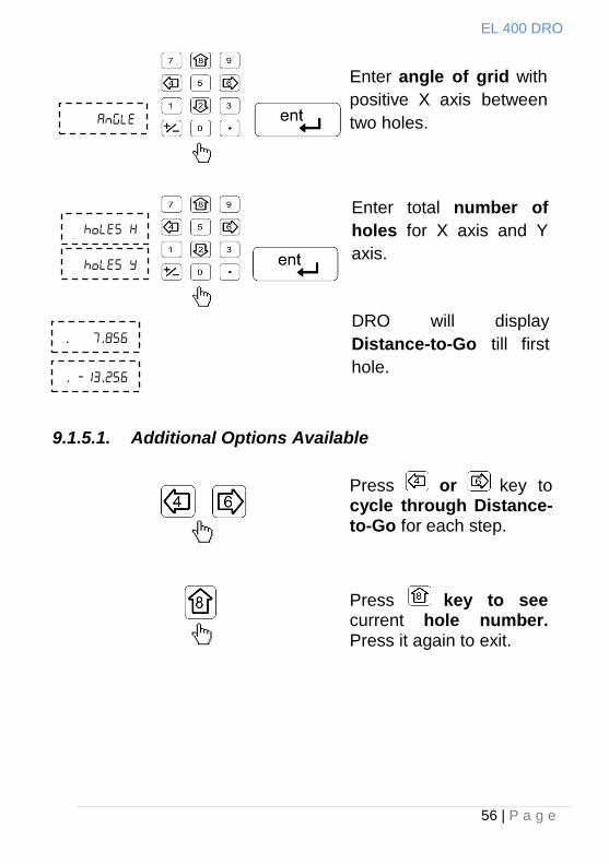
9.1.5.1. Additional Options Available
. .
. .
Enter angle of grid with
positive X axis between
two holes.
Enter total number of
holes for X axis and Y
axis.
DRO will display
Distance-to-Go till first
hole.
Press or key to cycle through Distance-to-Go for each step.
Press key to see current hole number. Press it again to exit.
EL 400 DRO
57 | P a g e
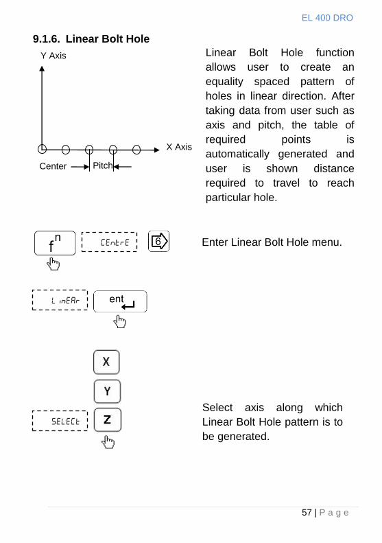
9.1.6. Linear Bolt Hole
Center
X Axis
Y Axis
Pitch
Linear Bolt Hole function
allows user to create an
equality spaced pattern of
holes in linear direction. After
taking data from user such as
axis and pitch, the table of
required points is
automatically generated and
user is shown distance
required to travel to reach
particular hole.
Enter Linear Bolt Hole menu.
Select axis along which
Linear Bolt Hole pattern is to
be generated.
EL 400 DRO
58 | P a g e
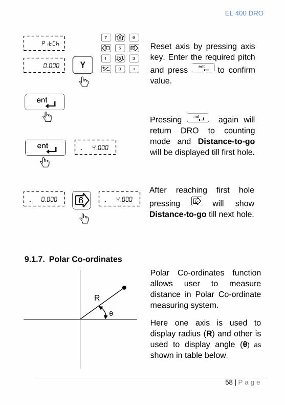
..
.. ..
9.1.7. Polar Co-ordinates
.
Reset axis by pressing axis
key. Enter the required pitch
and press to confirm
value.
Pressing again will
return DRO to counting
mode and Distance-to-go
will be displayed till first hole.
After reaching first hole
pressing will show
Distance-to-go till next hole.
θ
R
Polar Co-ordinates function
allows user to measure
distance in Polar Co-ordinate
measuring system.
Here one axis is used to
display radius (R) and other is
used to display angle (θ) as
shown in table below.
EL 400 DRO
59 | P a g e
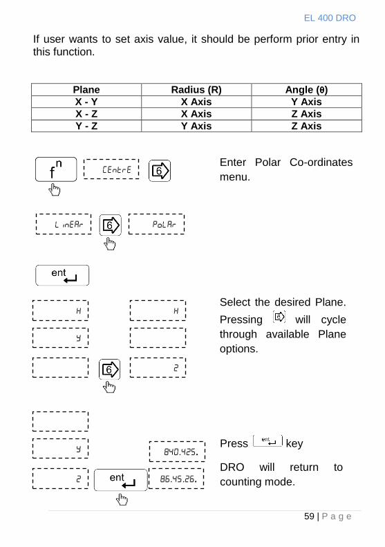
If user wants to set axis value, it should be perform prior entry in this function.
Plane Radius (R) Angle (θ)
X - Y X Axis Y Axis
X - Z X Axis Z Axis
Y - Z Y Axis Z Axis
Enter Polar Co-ordinates
menu.
Select the desired Plane.
Pressing will cycle
through available Plane
options.
..
...
Press key
DRO will return to
counting mode.
EL 400 DRO
60 | P a g e
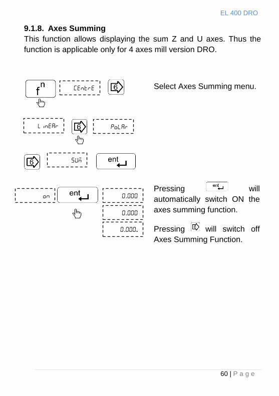
9.1.8. Axes Summing
This function allows displaying the sum Z and U axes. Thus the
function is applicable only for 4 axes mill version DRO.
Select Axes Summing menu.
.
.
..
Pressing will
automatically switch ON the
axes summing function.
Pressing will switch off
Axes Summing Function.
EL 400 DRO
61 | P a g e
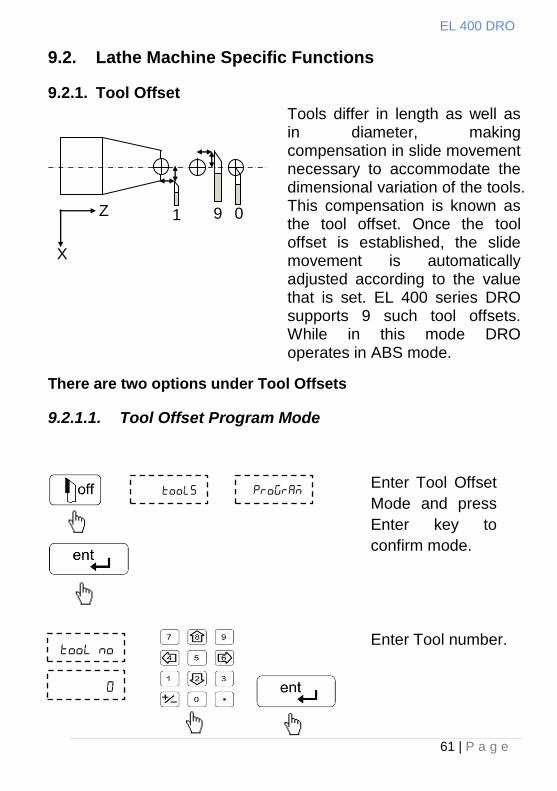
9.2. Lathe Machine Specific Functions
9.2.1. Tool Offset
Tools differ in length as well as in diameter, making compensation in slide movement necessary to accommodate the dimensional variation of the tools. This compensation is known as the tool offset. Once the tool offset is established, the slide movement is automatically adjusted according to the value that is set. EL 400 series DRO supports 9 such tool offsets. While in this mode DRO operates in ABS mode.
There are two options under Tool Offsets
9.2.1.1. Tool Offset Program Mode
Enter Tool Offset
Mode and press
Enter key to
confirm mode.
Enter Tool number.
X
Z 1 9 0
EL 400 DRO
62 | P a g e
.
.
.
.
.
.
.
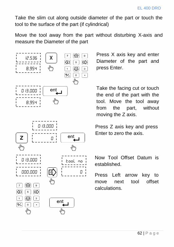
Take the slim cut along outside diameter of the part or touch the
tool to the surface of the part (if cylindrical)
Move the tool away from the part without disturbing X-axis and
measure the Diameter of the part
Press X axis key and enter
Diameter of the part and
press Enter.
Take the facing cut or touch
the end of the part with the
tool. Move the tool away
from the part, without
moving the Z axis.
Press Z axis key and press
Enter to zero the axis.
Now Tool Offset Datum is
established.
Press Left arrow key to
move next tool offset
calculations.
EL 400 DRO
63 | P a g e
.
.
.
.
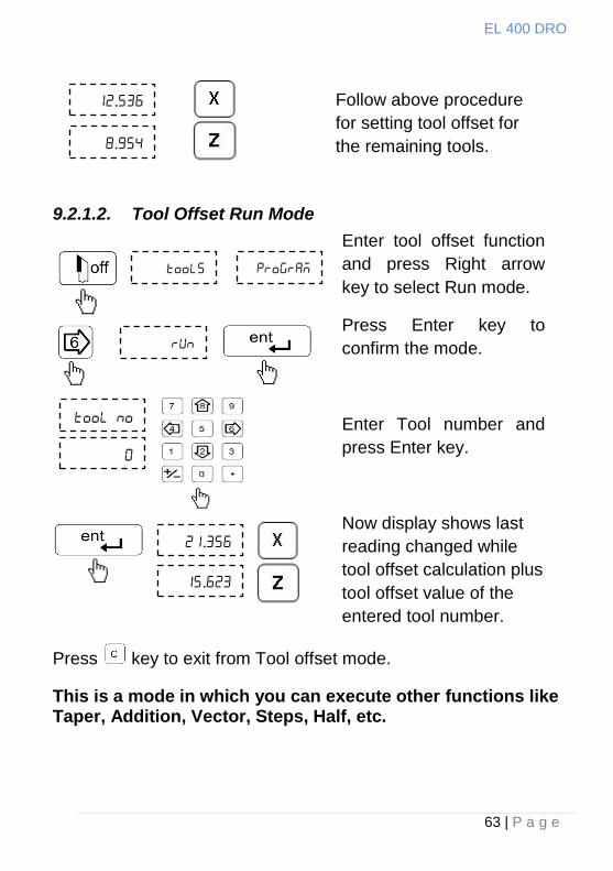
9.2.1.2. Tool Offset Run Mode
Press key to exit from Tool offset mode.
This is a mode in which you can execute other functions like Taper, Addition, Vector, Steps, Half, etc.
Enter tool offset function
and press Right arrow
key to select Run mode.
Press Enter key to
confirm the mode.
Enter Tool number and
press Enter key.
Now display shows last
reading changed while
tool offset calculation plus
tool offset value of the
entered tool number.
Follow above procedure
for setting tool offset for
the remaining tools.
EL 400 DRO
64 | P a g e
.
.
Press Enter key to confirm
Tool No.
Now display shows last
reading changed while tool
offset calculation plus tool
offset value of the selected
tool no.
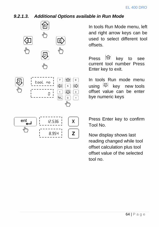
9.2.1.3. Additional Options available in Run Mode
In tools Run Mode menu, left
and right arrow keys can be
used to select different tool
offsets.
Press key to see current tool number Press Enter key to exit.
In tools Run mode menu
using key new tools offset value can be enter bye numeric keys
EL 400 DRO
65 | P a g e
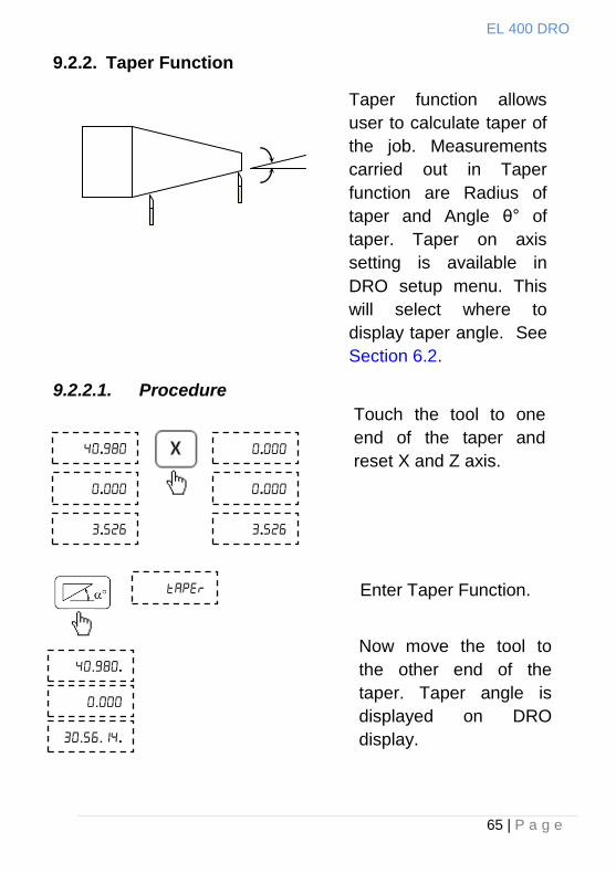
9.2.2. Taper Function
9.2.2.1. Procedure
.
.
.
.
.
.
Touch the tool to one
end of the taper and
reset X and Z axis.
Enter Taper Function.
function
..
.
...
.
Now move the tool to
the other end of the
taper. Taper angle is
displayed on DRO
display.
Taper function allows
user to calculate taper of
the job. Measurements
carried out in Taper
function are Radius of
taper and Angle θ° of
taper. Taper on axis
setting is available in
DRO setup menu. This
will select where to
display taper angle. See
Section 6.2.
EL 400 DRO
66 | P a g e
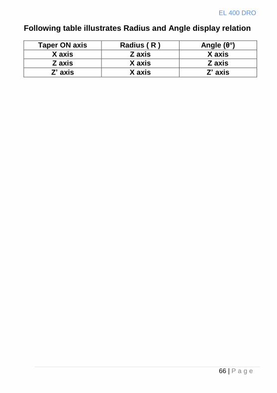
Following table illustrates Radius and Angle display relation
Taper ON axis Radius ( R ) Angle (θ°)
X axis Z axis X axis
Z axis X axis Z axis
Z’ axis X axis Z’ axis
EL 400 DRO
67 | P a g e
Z‟
X
Z
X
Z
Z‟
Combined
Movement
Combined
Movement
X + Z‟ Z + Z‟
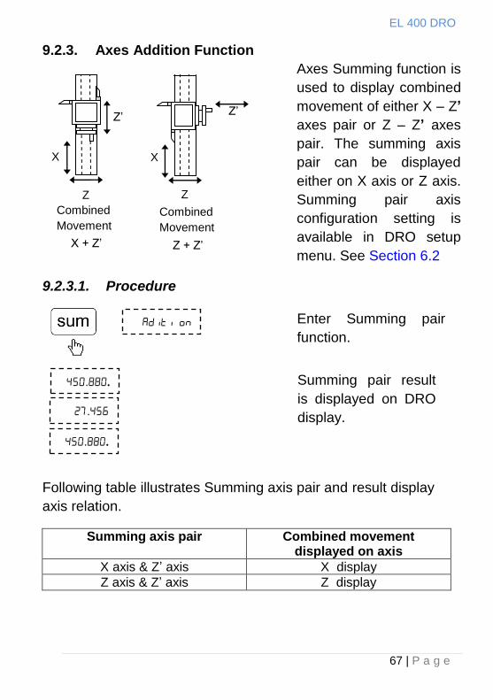
9.2.3. Axes Addition Function
Axes Summing function is
used to display combined
movement of either X – Z’
axes pair or Z – Z’ axes
pair. The summing axis
pair can be displayed
either on X axis or Z axis.
Summing pair axis
configuration setting is
available in DRO setup
menu. See Section 6.2
9.2.3.1. Procedure
Following table illustrates Summing axis pair and result display
axis relation.
Summing axis pair Combined movement displayed on axis
X axis & Z‟ axis X display
Z axis & Z‟ axis Z display
Enter Summing pair
function.
..
.
..
Summing pair result
is displayed on DRO
display.
EL 400 DRO
68 | P a g e
Z‟
X
Z
Combined Movement X = X + Z‟ (Sin α)
Combined Movement Z = Z + Z‟ (Cos α)
Vector Angle α
9.2.4. Vectoring Function
Vectoring function is used
for displaying combined
movement of either X – Z‟
axis pair or Z – Z‟ axis
pair taking into
consideration angle
between Z and Z‟ i.e. α.
The resulting combined
movement is displayed on
X and Z axis.
9.2.4.1. Procedure
Following table illustrates combined movement and display
relation
Combined Axis Movement
Combined Movement displayed on
X + Z‟ (Sin α) X display
Z + Z‟ (Cos α) Z display
Select Vectoring function
.
Enter angle between
Z and Z‟ axis.
.. Resulting combined
movement will be
shown on DRO
display.
..
..
EL 400 DRO
69 | P a g e
9.3. EDM Machine Specific Functions
9.3.1. Circular Bolt Hole Function
See Section 9.1.1
9.3.2. Arc Bolt Hole Function
For EDM machine specific DRO a dedicated key is
provided for this function. For more details see Section 9.1.2.
9.3.3. Angle Hole Function
See Section 9.1.4
9.3.4. Pre-Set Depth (PSD) Function
PSD feature is used to control relay at a pre-set depth setting. This
feature is widely used in Electric discharge machines (EDM) where
sparking process has to be stopped after reaching the required
preset depth value.
This feature is available only for Z-axis in case of 3 axes DRO and
on X axis in case of 1 Axis DRO.
PSD is also sometimes referred as Single Output function.
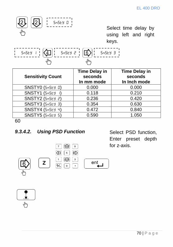
9.3.4.1. Setting for Time Delay
There are six pre-defined delay settings available which can be set
as follows
Enter Auxiliary setup
menu. …
Note that this option is
available only on Z axis
for 3 axes DRO and on
X axis in case of 1 axis
DRO.
EL 400 DRO
70 | P a g e
Sensitivity Count Time Delay in
seconds In mm mode
Time Delay in seconds
In Inch mode
SNSTY0 () 0.000 0.000
SNSTY1 () 0.118 0.210
SNSTY2 () 0.236 0.420
SNSTY3 () 0.354 0.630
SNSTY4 () 0.472 0.840
SNSTY5 () 0.590 1.050
60
9.3.4.2. Using PSD Function
Select PSD function,
Enter preset depth
for z-axis.
Select time delay by
using left and right
keys.
EL 400 DRO
71 | P a g e
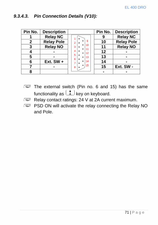
9.3.4.3. Pin Connection Details (V10):
Pin No. Description Pin No. Description
1 Relay NC 1
2
3
4
5
6
7
8
9
10
11
12
13
14
15
9 Relay NC
2 Relay Pole 10 Relay Pole
3 Relay NO 11 Relay NO
4 - 12 -
5 - 13 -
6 Ext. SW + 14 -
7 - 15 Ext. SW -
8 - -
The external switch (Pin no. 6 and 15) has the same
functionality as key on keyboard.
Relay contact ratings: 24 V at 2A current maximum.
PSD ON will activate the relay connecting the Relay NO
and Pole.
EL 400 DRO
72 | P a g e
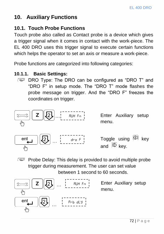
10. Auxiliary Functions
10.1. Touch Probe Functions
Touch probe also called as Contact probe is a device which gives
a trigger signal when it comes in contact with the work-piece. The
EL 400 DRO uses this trigger signal to execute certain functions
which helps the operator to set an axis or measure a work-piece.
Probe functions are categorized into following categories:
10.1.1. Basic Settings:
DRO Type: The DRO can be configured as “DRO T” and
“DRO F” in setup mode. The “DRO T” mode flashes the
probe message on trigger. And the “DRO F” freezes the
coordinates on trigger.
Probe Delay: This delay is provided to avoid multiple probe
trigger during measurement. The user can set value
between 1 second to 60 seconds.
o
Enter Auxiliary setup
menu.
…
…
Toggle using key
and key.
Enter Auxiliary setup
menu.
…
…
EL 400 DRO
73 | P a g e
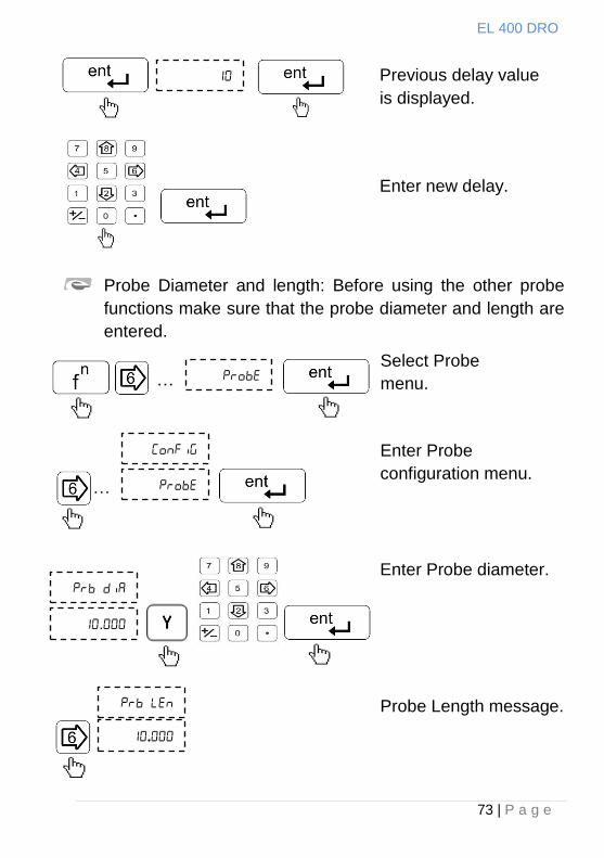
Probe Diameter and length: Before using the other probe
functions make sure that the probe diameter and length are
entered.
Select Probe
menu.
Enter Probe
configuration menu.
Enter Probe diameter.
Probe Length message.
.
Previous delay value
is displayed.
Enter new delay.
value.
…
…
.
EL 400 DRO
74 | P a g e
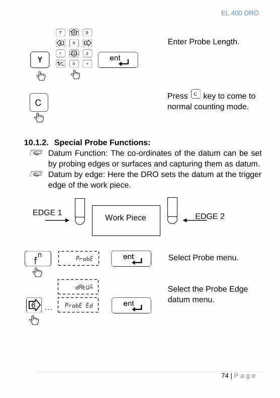
10.1.2. Special Probe Functions:
Datum Function: The co-ordinates of the datum can be set
by probing edges or surfaces and capturing them as datum.
Datum by edge: Here the DRO sets the datum at the trigger
edge of the work piece.
Select Probe menu.
Select the Probe Edge
datum menu.
EDGE 1 EDGE 2 Work Piece
Enter Probe Length.
…
Press key to come to
normal counting mode.
EL 400 DRO
75 | P a g e
The DRO receives the trigger pulse form the probe and sets the
datum accordingly. (After the trigger pulse the DRO waits for the
user to set the axis at the datum point) When the trigger pulse is
sensed user can enter the desired co-ordinates of the datum.
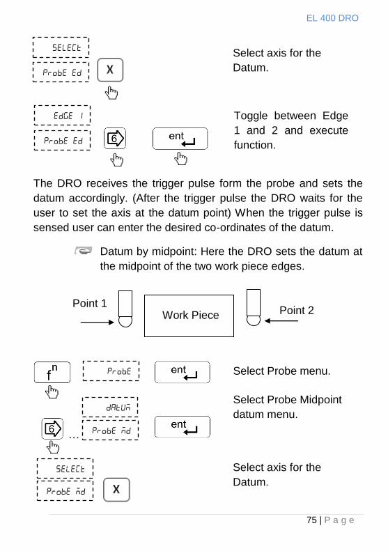
Datum by midpoint: Here the DRO sets the datum at
the midpoint of the two work piece edges.
Select axis for the
Datum.
Toggle between Edge
1 and 2 and execute
function.
Select Probe menu.
Select Probe Midpoint
datum menu.
Select axis for the
Datum.
Point 1 Point 2 Work Piece
…
EL 400 DRO
76 | P a g e
Move the probe towards work piece edge 1 till the DRO receives
first trigger pulse. Move the probe towards work piece edge 2 till
the DRO receives second trigger pulse. Enter the co-ordinates of
the midpoint as datum on selected axis.
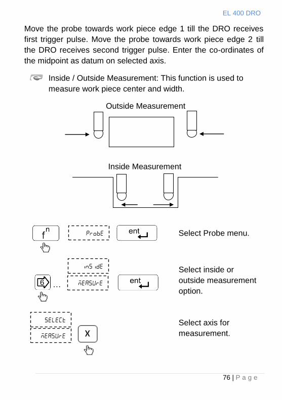
Inside / Outside Measurement: This function is used to
measure work piece center and width.
Outside Measurement
Inside Measurement
Select Probe menu.
Select inside or
outside measurement
option.
Select axis for
measurement.
…
EL 400 DRO
77 | P a g e
Move the probe towards work piece edge 1 till the DRO receives
first trigger pulse. Move the probe towards work piece edge 2 till
the DRO receives second trigger pulses. The display shows co-
ordinates of the center and width of the work piece on the selected
axis.
EL 400 DRO
78 | P a g e
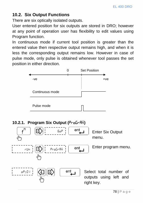
10.2. Six Output Functions
There are six optically isolated outputs.
User entered position for six outputs are stored in DRO; however
at any point of operation user has flexibility to edit values using
Program function.
In continuous mode if current tool position is greater than the
entered value then respective output remains high, and when it is
less the corresponding output remains low. However in case of
pulse mode, only pulse is obtained whenever tool passes the set
position in either direction.
10.2.1. Program Six Output ()
Enter Six Output
menu.
Enter program menu.
Select total number of
outputs using left and
right key.
0 Set Position
-ve +ve
Continuous mode
Pulse mode
EL 400 DRO
79 | P a g e
..
..
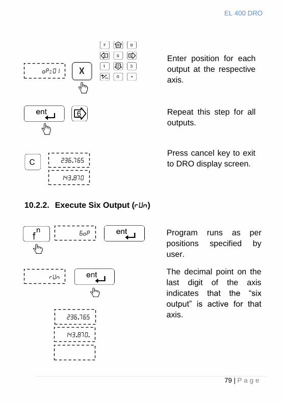
10.2.2. Execute Six Output ()
.
.
Enter position for each
output at the respective
axis.
Repeat this step for all
outputs.
Press cancel key to exit
to DRO display screen.
Program runs as per
positions specified by
user.
The decimal point on the
last digit of the axis
indicates that the “six
output” is active for that
axis. .
EL 400 DRO
80 | P a g e
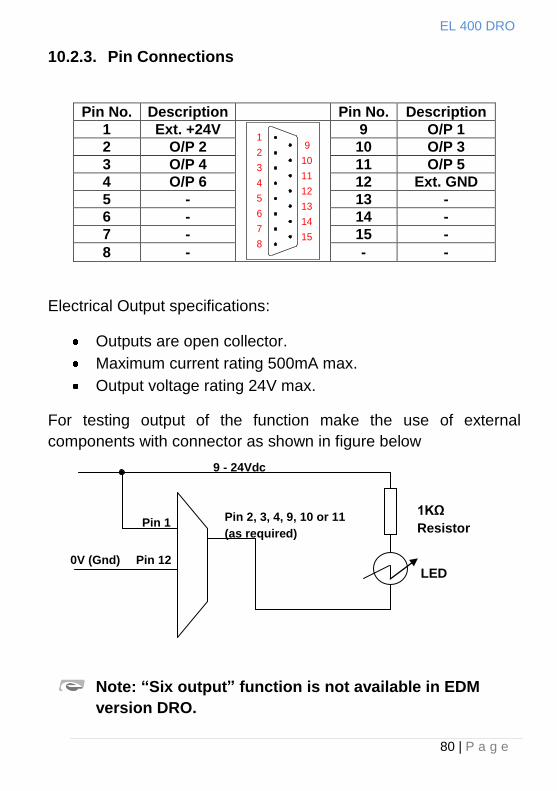
10.2.3. Pin Connections
Pin No. Description Pin No. Description
1 Ext. +24V 1
2
3
4
5
6
7
8
9
10
11
12
13
14
15
9 O/P 1
2 O/P 2 10 O/P 3
3 O/P 4 11 O/P 5
4 O/P 6 12 Ext. GND
5 - 13 -
6 - 14 -
7 - 15 -
8 - - -
Electrical Output specifications:
Outputs are open collector.
Maximum current rating 500mA max.
Output voltage rating 24V max.
For testing output of the function make the use of external
components with connector as shown in figure below
Note: “Six output” function is not available in EDM
version DRO.
9 - 24Vdc
1KΩ
Resistor
LED Pin 12
Pin 2, 3, 4, 9, 10 or 11
(as required) Pin 1
0V (Gnd)
EL 400 DRO
81 | P a g e
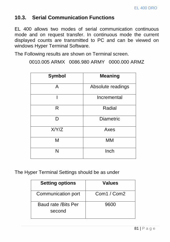
10.3. Serial Communication Functions
EL 400 allows two modes of serial communication continuous mode and on request transfer. In continuous mode the current displayed counts are transmitted to PC and can be viewed on windows Hyper Terminal Software.
The Following results are shown on Terminal screen.
0010.005 ARMX 0086.980 ARMY 0000.000 ARMZ
Symbol Meaning
A Absolute readings
I Incremental
R Radial
D Diametric
X/Y/Z Axes
M MM
N Inch
The Hyper Terminal Settings should be as under
Setting options Values
Communication port Com1 / Com2
Baud rate /Bits Per
second
9600
EL 400 DRO
82 | P a g e
Date Bits 8
Parity None
Stop bits 1
Flow Control None
On request mode the current displayed counts are transferred to
PC by pressing key and can be viewed with EL300 PC Side
Utility software (Refer Software Utility Guide for details). If there is
a communication error between DRO and PC, DRO displays “Pc
fail” message.
Press key to exit the function.
EL 400 DRO
83 | P a g e
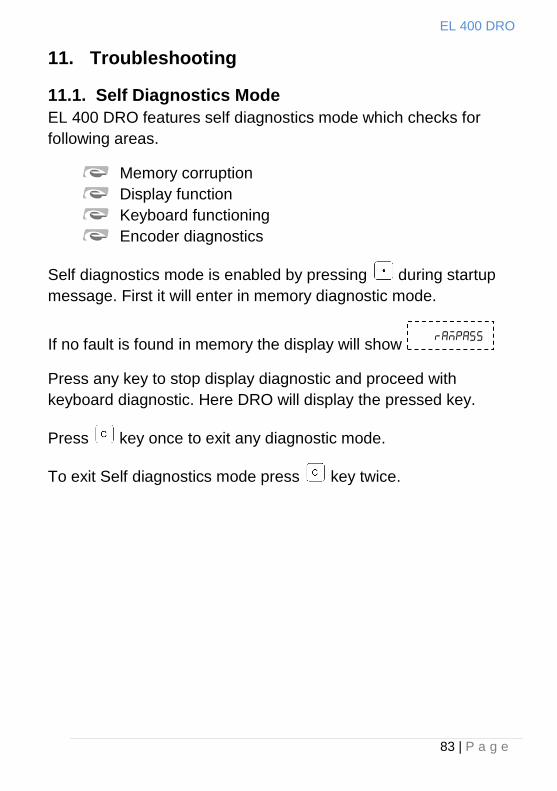
11. Troubleshooting
11.1. Self Diagnostics Mode
EL 400 DRO features self diagnostics mode which checks for
following areas.
Memory corruption
Display function
Keyboard functioning
Encoder diagnostics
Self diagnostics mode is enabled by pressing during startup
message. First it will enter in memory diagnostic mode.
If no fault is found in memory the display will show
Press any key to stop display diagnostic and proceed with
keyboard diagnostic. Here DRO will display the pressed key.
Press key once to exit any diagnostic mode.
To exit Self diagnostics mode press key twice.
EL 400 DRO
84 | P a g e
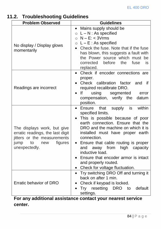
11.2. Troubleshooting Guidelines
Problem Observed Guidelines
No display / Display glows momentarily
Mains supply should be o L – N : As specified o N – E: < 3Vrms o L – E : As specified
Check the fuse. Note that if the fuse has blown, this suggests a fault with the Power source which must be corrected before the fuse is replaced.
Readings are incorrect
Check if encoder connections are proper.
Check calibration factor and if required recalibrate DRO.
If using segmented error compensation, verify the datum position.
The displays work, but give erratic readings, the last digit jitters or the measurements jump to new figures unexpectedly.
Ensure that supply is within specified limits.
This is possible because of poor earth connection. Ensure that the DRO and the machine on which it is installed must have proper earth connection.
Ensure that cable routing is proper and away from high capacity inductive load.
Ensure that encoder armor is intact and properly routed.
Check for voltage fluctuation.
Erratic behavior of DRO
Try switching DRO Off and turning it back on after 1 min.
Check if keypad is locked.
Try resetting DRO to default settings.
For any additional assistance contact your nearest service
center.
EL 400 DRO
85 | P a g e
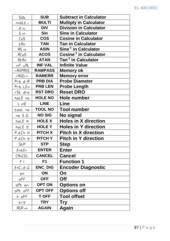
12. List of Display Text
VER Version
SELECT Select
LINEAR Linear measurement
ANGULAR Angular Measurement
SC Scale resolution
DP Display resolution
RAD Radial mode
DIA Diametric mode
RIGHT Right counting direction
LEFT Left counting direction
CALIB Calibration mode
LEC Linear error correction
SLEC Segmented linear error correction
DISPVAL Display value
CAL FAC Calibration factor
ENF ON Encoder fail ON
ENF OFF Encoder fail OFF
AUX Fn Auxiliary function settings
SERIAL Serial handshake mode
SER CON serial continues mode
DRO F DRO Freeze mode in probe sensing
DRO T DRO transmit mode in probe sensing
PRB DLY Probe sensing delay
LOC OFF Keyboard lock OFF
LOC ON Keyboard lock ON
SLEEP T Sleep timer
SAV CHG Save changes in Set up mode
RST OEM Reset to OEM settings
OEM MOD OEM mode
END End of SET UP mode
HOME Home function
MC REF Machine reference function
SET MC Set machine reference
TOOLS Tool offset function
PROGRAM Program SDMs
EL 400 DRO
86 | P a g e
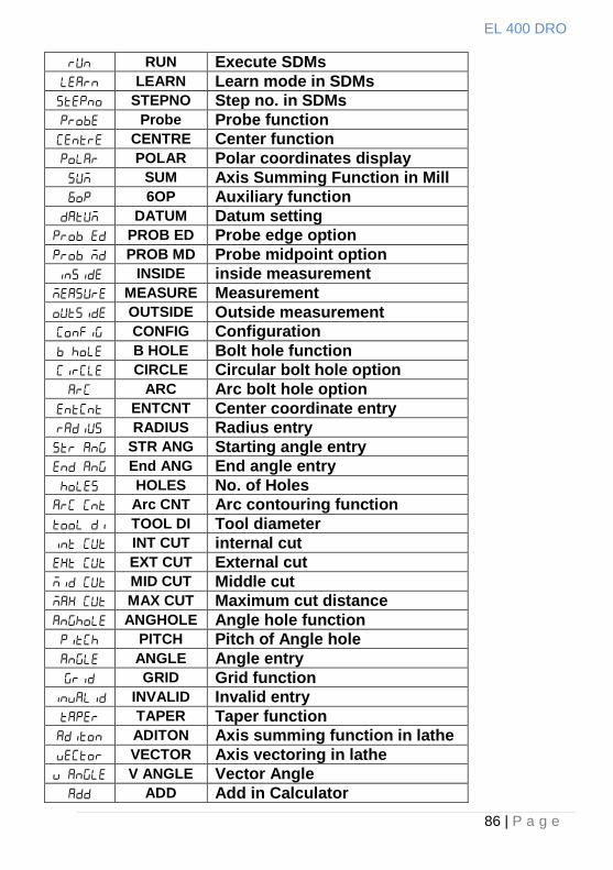
RUN Execute SDMs
LEARN Learn mode in SDMs
STEPNO Step no. in SDMs
Probe Probe function
CENTRE Center function
POLAR Polar coordinates display
SUM Axis Summing Function in Mill
6OP Auxiliary function
DATUM Datum setting
PROB ED Probe edge option
PROB MD Probe midpoint option
INSIDE inside measurement
MEASURE Measurement
OUTSIDE Outside measurement
CONFIG Configuration
B HOLE Bolt hole function
CIRCLE Circular bolt hole option
ARC Arc bolt hole option
ENTCNT Center coordinate entry
RADIUS Radius entry
STR ANG Starting angle entry
End ANG End angle entry
HOLES No. of Holes
Arc CNT Arc contouring function
TOOL DI Tool diameter
INT CUT internal cut
EXT CUT External cut
MID CUT Middle cut
MAX CUT Maximum cut distance
ANGHOLE Angle hole function
PITCH Pitch of Angle hole
ANGLE Angle entry
GRID Grid function
INVALID Invalid entry
TAPER Taper function
ADITON Axis summing function in lathe
VECTOR Axis vectoring in lathe
V ANGLE Vector Angle
ADD Add in Calculator
EL 400 DRO
87 | P a g e
SUB Subtract in Calculator
MULTI Multiply in Calculator
DIV Division in Calculator
Sin Sine in Calculator
COS Cosine in Calculator
TAN Tan in Calculator
ASIN Sine-1 in Calculator
ACOS Cosine-1 in Calculator
ATAN Tan-1 in Calculator
INF VAL Infinite Value
RAMPASS Memory ok
RAMERR Memory error
PRB DIA Probe Diameter
PRB LEN Probe Length
RST DRO Reset DRO
HOLE NO Hole number
LINE Line
TOOL NO Tool number
NO SIG No signal
HOLE X Holes in X direction
HOLE Y Holes in Y direction
PITCH X Pitch in X direction
PITCH Y Pitch in Y direction
STP Step
ENTER Enter
CANCEL Cancel
F1 Function 1
ENC_DIG Encoder Diagnostic
ON On
OFF Off
OPT ON Options on
OPT OFF Options off
T OFF Tool offset
TRY Try
AGAIN Again
EL 400 DRO
88 | P a g e
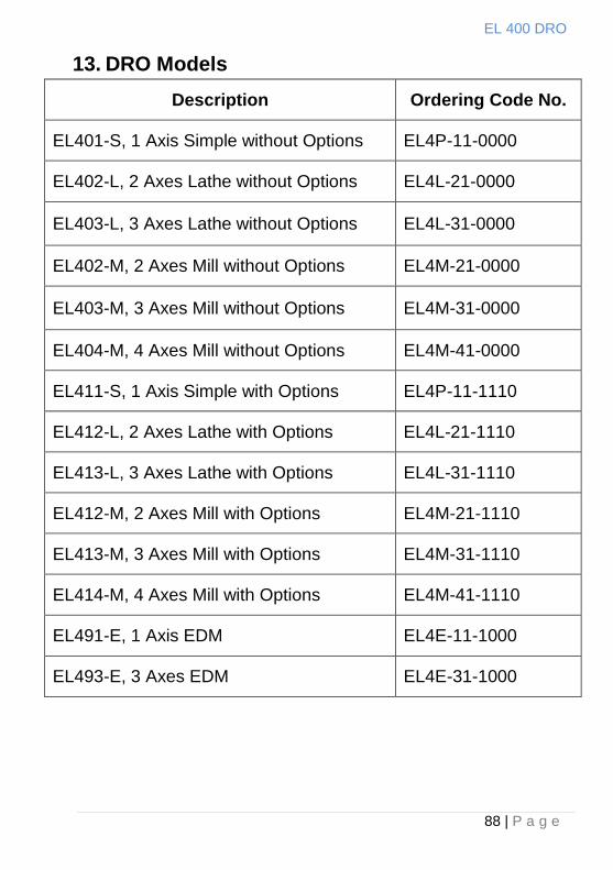
13. DRO Models
Description Ordering Code No.
EL401-S, 1 Axis Simple without Options EL4P-11-0000
EL402-L, 2 Axes Lathe without Options EL4L-21-0000
EL403-L, 3 Axes Lathe without Options EL4L-31-0000
EL402-M, 2 Axes Mill without Options EL4M-21-0000
EL403-M, 3 Axes Mill without Options EL4M-31-0000
EL404-M, 4 Axes Mill without Options EL4M-41-0000
EL411-S, 1 Axis Simple with Options EL4P-11-1110
EL412-L, 2 Axes Lathe with Options EL4L-21-1110
EL413-L, 3 Axes Lathe with Options EL4L-31-1110
EL412-M, 2 Axes Mill with Options EL4M-21-1110
EL413-M, 3 Axes Mill with Options EL4M-31-1110
EL414-M, 4 Axes Mill with Options EL4M-41-1110
EL491-E, 1 Axis EDM EL4E-11-1000
EL493-E, 3 Axes EDM EL4E-31-1000
EL 400 DRO
89 | P a g e
Code No: 0073-14-0960 Code No : 0073-14-0961 Revision Date : 22th Oct, 2010
Sales Office:
Electronica Mechatronic Systems (I) Pvt. Ltd., Electronica House, 2 Nursery Court,
Kibworth, Leicestershire, LE8 0EX, United Kingdom,
Phone: +44 (0) 116 279 68 91 Fax: +44 (0) 116 279 67 02
Email: [email protected] Web: www.electronicaems.co.uk
Factory: Electronica Mechatronic Systems (India) Pvt. Ltd.,
Unit No. 37&44, Electronic Co-operative Estate, Pune-Satara road, Pune – 411009
Maharashtra, India Phone: +91 (020) 2422 4440, 2422 9398,
Fax: +91 (020) 2422 1881 Email: [email protected]
Web: www.electronicaems.com
Electronica Mechatronic Systems (I) Pvt. Ltd. Is a division of Electronica Mechatronic Systems (India) Pvt. Ltd.


![FPS1xl EL/GG - Salamander Designs OLE ECTIVE LA TANDS ... FPS1XL/EL/GG E479586. T )S\L/PSSZ(]L )SVVTÄLSK *; ... Horizontal - 400, 600mm, 800mm, 1000mm, 1200mm](https://img.pdfslide.us/doc/110x75/5b037bd77f8b9a0a548c3c02/fps1xl-elgg-salamander-designs-ole-ective-la-tands-fps1xlelgg-e479586.jpg)
![[XLS]obcindia.co.inobcindia.co.in/obcnew/upload/obc/Unpaid Dividend 2013-14... · Web view400 400 400 400 400 400 400 400 400 400 400 400 400 400 400 400 400 400 400 400 400 400 400](https://img.pdfslide.us/doc/110x75/5aa6f94e7f8b9a54748b6a16/xls-dividend-2013-14web-view400-400-400-400-400-400-400-400-400-400-400-400.jpg)