Embed Size (px)
DESCRIPTION
pv
Citation preview
European Journal of Scientific Research ISSN 1450-216X Vol.33 No.3 (2009), pp.515-524 © EuroJournals Publishing, Inc. 2009 http://www.eurojournals.com/ejsr.htm
A New Controller Scheme for Photovoltaics Power
Generation Systems
Tamer T.N. Khatib National University of Malaysia, Department of Electrical
Electronic & System Engineering Bangi 43600, Selangor, Malaysia E-mail: [email protected]
Azah Mohamed
National University of Malaysia, Department of Electrical Electronic & System Engineering Bangi 43600, Selangor, Malaysia
E-mail: [email protected]
Nowshad Amin National University of Malaysia, Department of Electrical
Electronic & System Engineering Bangi 43600, Selangor, Malaysia E-mail: [email protected]
Abstract
This paper presents a new controller scheme for photovoltaic (PV) power generation systems. The proposed PV controller scheme controls both the boost converter and the battery charger by using a microcontroller in order to extract maximum power from the PV array and control the charging process of the battery. The objective of the paper is to present a cost effective boost converter design and an improved maximum power point tracking algorithm for the PV system. A MATLAB based simulation model of the proposed standalone PV system has been developed to evaluate the feasibility of the system in ensuring maximum power point operation
1. Introduction Recently, the installation of PV generation systems is rapidly growing due to concerns related to environment, global warming, energy security, technology improvements and decreasing costs. PV generation system is considered as a clean and environmentally-friendly source of energy. The main applications of PV systems are in either standalone or grid connected configurations. Standalone PV generation systems are attractive as indispensable electricity source for remote areas [1]. However, PV generation systems have two major problems which are related to low conversion efficiency of about 9 to 12 % especially in low irradiation conditions and the amount of electric power generated by PV arrays varies continuously with weather conditions. Therefore, many research works are done to increase the efficiency of the energy produced from the PV arrays [2]
The solar cell V-I characteristics is nonlinear and varies with irradiation and temperature. But there is a unique point on the V-I and P-V curves, called as the maximum power point (MPP), at which at this point the PV system is said to operate with maximum efficiency and produces its maximum power output. The location of the MPP is not known but can be traced by either through calculation models or search algorithms. Thus, maximum power point tracking (MPPT) techniques are needed to
A New Controller Scheme for Photovoltaics Power Generation Systems 516
maintain the PV array’s operating point at its MPP. Many MPPT techniques have been proposed in the literature in which the techniques vary in many aspects, including simplicity, convergence speed, hardware implementation and range of effectiveness. However, the most widely used MPPT technique is the perturbation and observation (P&O) method. This paper presents a simple MPPT algorithm which can be easily implemented and adopted for low cost PV applications. The objective of this paper is to design a novel PV controller scheme with improved MPPT method.
The proposed standalone PV controller implementation takes into account mathematical model of each component as well as actual component specification. The dc–dc or boost converter is the front-end component connected between the PV array and the load. The conventional boost converter may cause serious reverse recovery problem and increase the rating of all devices. As a result, the conversion efficiency is degraded and the electromagnetic interference problem becomes severe under this situation. To increase the conversion efficiency, many modified step-up converter topologies have been investigated by several researchers. Voltage clamped techniques have been incorporated in the converter design to overcome the severe reverse-recovery problem of the output diodes [3]. In this paper, focus is also given in the boost converter design. Another important component in the standalone PV systems is the charge controller which is used to save the battery from possible damage due to over-charging and over-discharging. Studies showed that the life time of a battery can be degraded without using a charge controller..
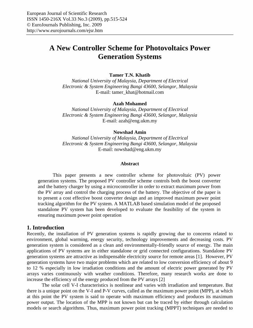
The proposed new controller scheme for the standalone PV system controls both the boost converter and the charge controller in two control steps. The first step is to control the boost converter so as to extract the maximum power point of the PV modules. Here, a high step-up converter is considered for the purpose of stepping up the PV voltage and consequently reducing the number of series-connected PV modules and to maintain a constant dc bus voltage. A microcontroller is used for data acquisition that gets PV module operating current and voltage and is also used to program the MPPT algorithm. The controller adopts the pulse width modulation (PWM) technique to increase the duty cycle of the generated pulses as the PV voltage decreases so as to obtain a stable output voltage and current close to the maximum power point. The second control step is to control the charge controller for the purpose of protecting the batteries. By controlling the charging current using the PWM technique and controlling the battery voltage during charging, voltages higher than the gassing voltage can be avoided. 2. Design of the Proposed Photovoltaic System Most of the standalone PV systems operate in one mode only such that the PV system charges the battery which in turns supply power to the load. In this mode of operation, the life cycle time of the battery may be reduced due to continuous charging and discharging of the battery. The proposed standalone PV system as shown in terms of a block diagram in Figure 1 is designed to operate in two modes: PV system supplies power directly to loads and when the radiation goes down and the produced energy is not enough, the PV system will charge the battery which in turns supply power to the load. To manage these modes of operation, a controller is connected to the boost converter by observing the PV output power
517 Tamer T.N. Khatib, Azah Mohamed and Nowshad Amin
Figure 1: Schematic diagram of the proposed PV system
2.1. Boost Converter
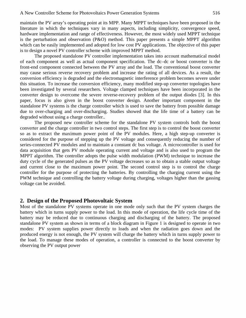
A boost converter is a power converter with an output DC voltage greater than its input DC voltage. It is a class of switching-mode power supply containing at least two semiconductor switches (a diode and a transistor) and at least one energy storage element. Filters made of capacitors in combination with inductors are normally added to the output of the converter to reduce output voltage ripple [4]. By implementing the pulse width modulation technology (PWM) techniques on the boost converter, a stable output voltage from a non stable input voltage can be obtained by changing the duty cycle of the switched input pulse. In this paper, an improved boost converter design is presented by modifying the voltage gain equation which is function of the duty cycle. The voltage gain can be increased by adding more clamping devises so as to deal with the severe reverse-recovery problem. Figure 2 shows the circuit diagram of the proposed boost converter consisting of an inductor in the primary side (L), clamping diodes, D1,D2, capacitor C2 used to form a regenerative circuit to sink the reverse recovery, high voltage capacitor, C1 and an output filter circuit formed with diode, Do and capacitor, Co.
Figure 2: Boost Converter Design
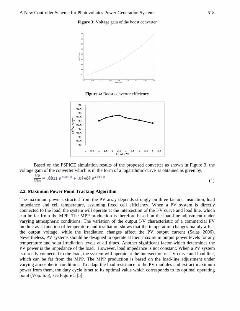
PSPICE simulation of the converter was done by considering the component values of C1= 1µF, C2 = 6.8 µF, Co = 680 µF and L=9 µH. D1, D2, D0 are Schottky diodes, Q is MOSFET IRFP2907, frequency, ƒ = 20 kHz. Figures 2 and 3 show the simulation results in terms of the converter voltage gain and efficiency which is about 93%, respectively, for the converter driving loads up to 5 kW
A New Controller Scheme for Photovoltaics Power Generation Systems 518
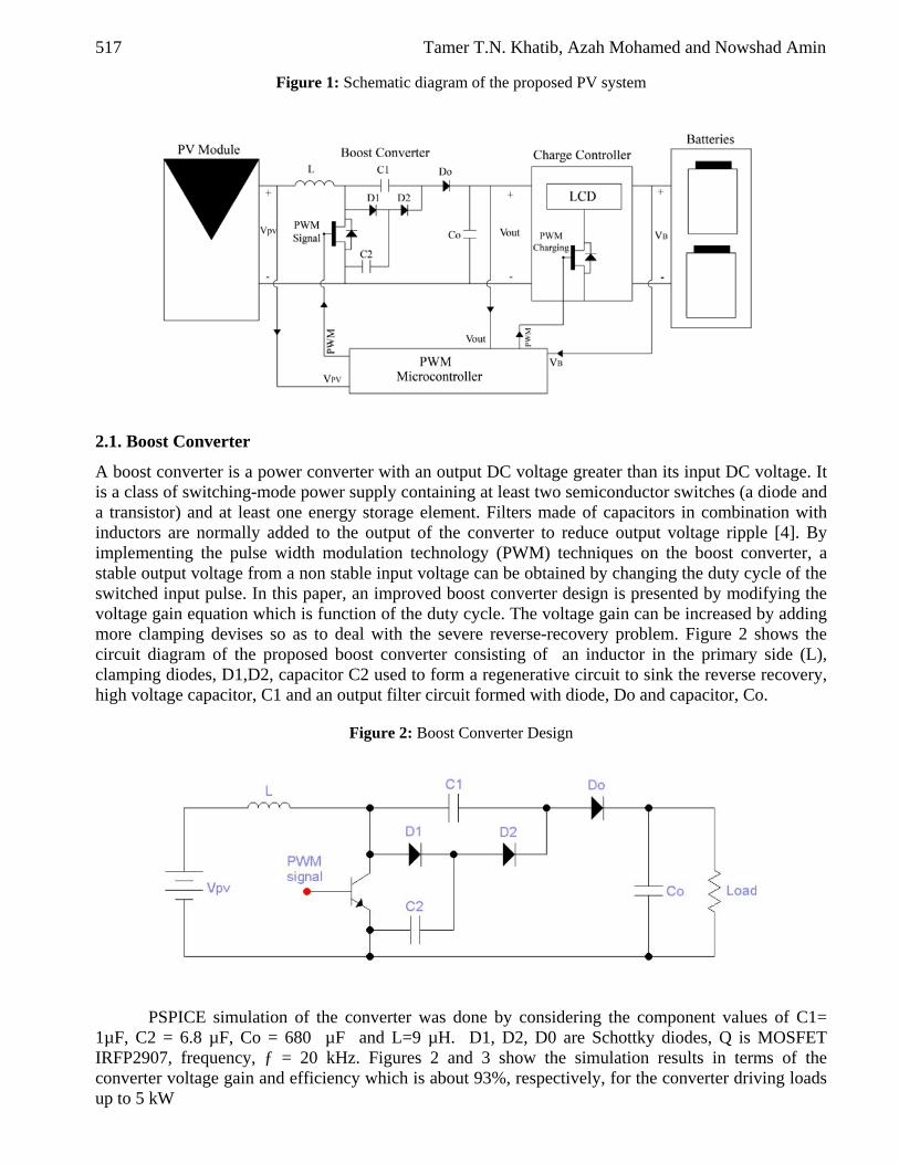
Figure 3: Voltage gain of the boost converter
0.1 0.15 0.2 0.25 0.3 0.35 0.4 0.45 0.51
1.1
1.2
1.3
1.4
1.5
1.6
1.7
1.8
1.9
Duty Cycle
Vlo
ad/V
mod
ule
Figure 4: Boost converter efficiency
Based on the PSPICE simulation results of the proposed converter as shown in Figure 3, the voltage gain of the converter which is in the form of a logarithmic curve is obtained as given by,
(1) 2.2. Maximum Power Point Tracking Algorithm
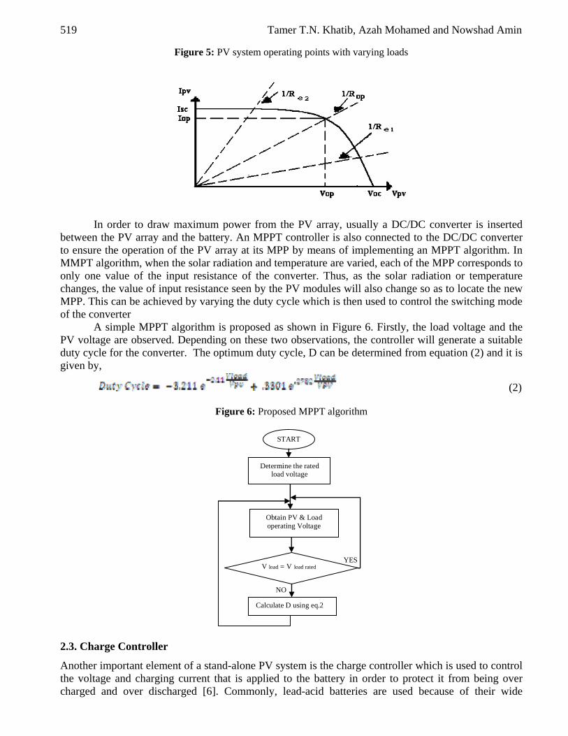
The maximum power extracted from the PV array depends strongly on three factors: insulation, load impedance and cell temperature, assuming fixed cell efficiency. When a PV system is directly connected to the load, the system will operate at the intersection of the I-V curve and load line, which can be far from the MPP. The MPP production is therefore based on the load-line adjustment under varying atmospheric conditions. The variation of the output I-V characteristic of a commercial PV module as a function of temperature and irradiation shows that the temperature changes mainly affect the output voltage, while the irradiation changes affect the PV output current (Salas 2006). Nevertheless, PV systems should be designed to operate at their maximum output power levels for any temperature and solar irradiation levels at all times. Another significant factor which determines the PV power is the impedance of the load. However, load impedance is not constant. When a PV system is directly connected to the load, the system will operate at the intersection of I-V curve and load line, which can be far from the MPP. The MPP production is based on the load-line adjustment under varying atmospheric conditions. To adapt the load resistance to the PV modules and extract maximum power from them, the duty cycle is set to its optimal value which corresponds to its optimal operating point (Vop. Iop), see Figure 5 [5]
519 Tamer T.N. Khatib, Azah Mohamed and Nowshad Amin
Figure 5: PV system operating points with varying loads
In order to draw maximum power from the PV array, usually a DC/DC converter is inserted between the PV array and the battery. An MPPT controller is also connected to the DC/DC converter to ensure the operation of the PV array at its MPP by means of implementing an MPPT algorithm. In MMPT algorithm, when the solar radiation and temperature are varied, each of the MPP corresponds to only one value of the input resistance of the converter. Thus, as the solar radiation or temperature changes, the value of input resistance seen by the PV modules will also change so as to locate the new MPP. This can be achieved by varying the duty cycle which is then used to control the switching mode of the converter
A simple MPPT algorithm is proposed as shown in Figure 6. Firstly, the load voltage and the PV voltage are observed. Depending on these two observations, the controller will generate a suitable duty cycle for the converter. The optimum duty cycle, D can be determined from equation (2) and it is given by,
(2)
Figure 6: Proposed MPPT algorithm
YES
NO
START
Determine the rated load voltage
Obtain PV & Load operating Voltage
V load = V load rated
Calculate D using eq.2
2.3. Charge Controller
Another important element of a stand-alone PV system is the charge controller which is used to control the voltage and charging current that is applied to the battery in order to protect it from being over charged and over discharged [6]. Commonly, lead-acid batteries are used because of their wide
A New Controller Scheme for Photovoltaics Power Generation Systems 520
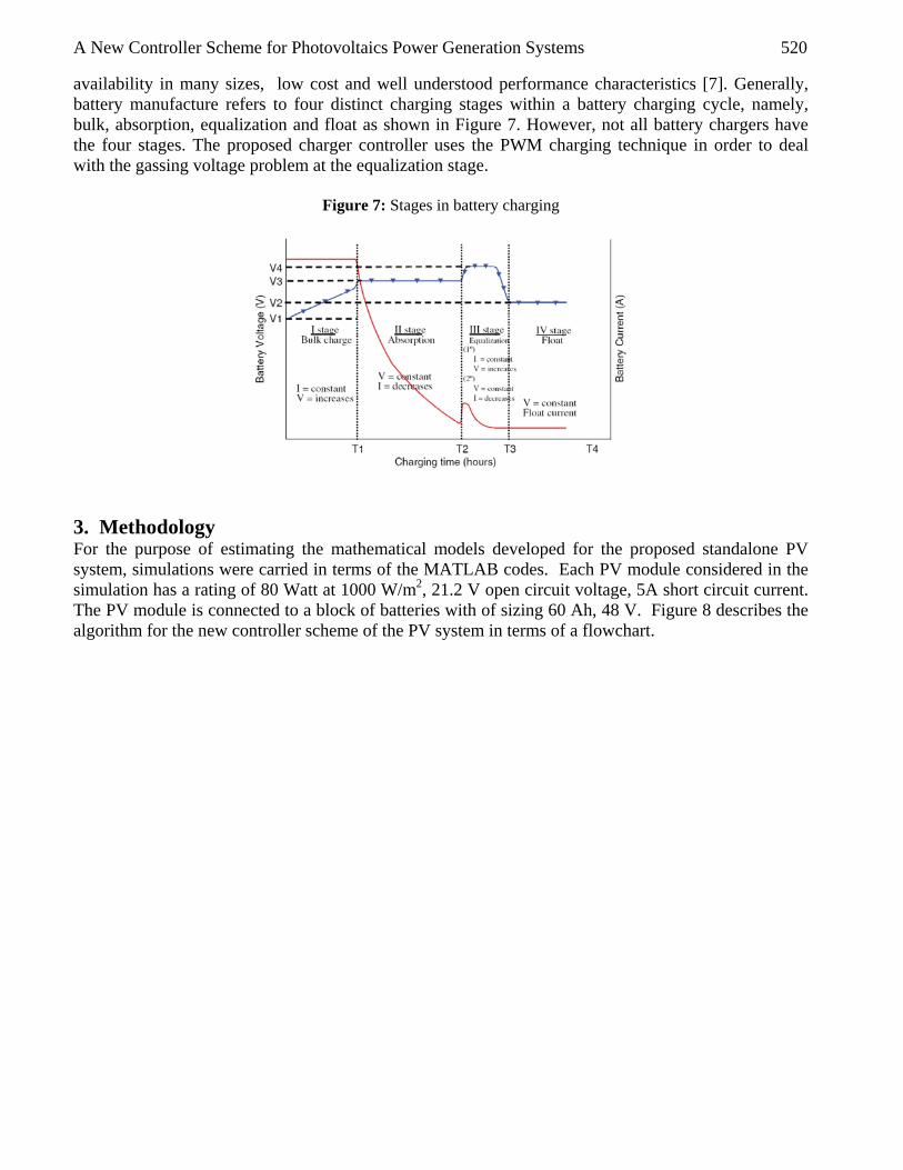
availability in many sizes, low cost and well understood performance characteristics [7]. Generally, battery manufacture refers to four distinct charging stages within a battery charging cycle, namely, bulk, absorption, equalization and float as shown in Figure 7. However, not all battery chargers have the four stages. The proposed charger controller uses the PWM charging technique in order to deal with the gassing voltage problem at the equalization stage.
Figure 7: Stages in battery charging
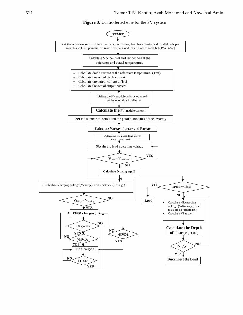
3. Methodology For the purpose of estimating the mathematical models developed for the proposed standalone PV system, simulations were carried in terms of the MATLAB codes. Each PV module considered in the simulation has a rating of 80 Watt at 1000 W/m2, 21.2 V open circuit voltage, 5A short circuit current. The PV module is connected to a block of batteries with of sizing 60 Ah, 48 V. Figure 8 describes the algorithm for the new controller scheme of the PV system in terms of a flowchart.
521 Tamer T.N. Khatib, Azah Mohamed and Nowshad Amin
Figure 8: Controller scheme for the PV system
YES NO
YESYES
NO
YES
YES
YES
NO
NO
NO
NO
Set the reference test conditions: Isc, Voc, Irradiation, Number of series and parallel cells per modules, cell temperature, air mass and speed and the area of the module [(dV/dI)Voc]
Calculate Voc per cell and Isc per cell at the reference and actual temperatures
• Calculate diode current at the reference temperature (Tref) • Calculate the actual diode current • Calculate the output current at Tref • Calculate the actual output current
Calculate the PV module current
Define the PV module voltage obtained from the operating irradiation
Set the number of series and the parallel modules of the PVarray
Calculate Varray, I array and Parray
• Calculate charging voltage (Vcharge) and resistance (Rcharge)
START
VBttery > Vgassing
PWM charging
>9 cycles
>HVD2
No Charging
>HVR
>HVD1
Determine the rated load power ppowerpowervoltage
Obtain the load operating voltage
Vload = Vload rated
Calculate D using eqn.2
Parray >= Pload
Load • Calculate discharging voltage (Vdischarge) and resistance (Rdischarge)
• Calculate Vbattery
Calculate the Depth of charge ( DOD )
>.75
Disconnect the Load
YES
YES
NO
NO
A New Controller Scheme for Photovoltaics Power Generation Systems 522
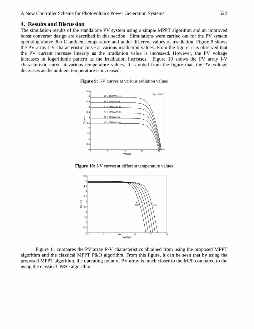
4. Results and Discussion The simulation results of the standalone PV system using a simple MPPT algorithm and an improved boost converter design are described in this section. Simulations were carried out for the PV system operating above 30o C ambient temperature and under different values of irradiation. Figure 9 shows the PV array I-V characteristic curve at various irradiation values. From the figure, it is observed that the PV current increase linearly as the irradiation value is increased. However, the PV voltage increases in logarithmic pattern as the irradiation increases. Figure 10 shows the PV array I-V characteristic curve at various temperature values. It is noted from the figure that, the PV voltage decreases as the ambient temperature is increased.
Figure 9: I-V curves at various radiation values
0 5 10 15 200
0.5
1
1.5
2
2.5
3
3.5
4
4.5
5
5.5
Voltage
Cur
rent
G = 500W/m.m
G = 600W/m.m
G = 700W/m.m
G = 800W/m.m
G = 900W/m.m
G = 1000W/m.mTa = 30 C
Figure 10: I-V curves at different temperature values
0 5 10 15 20 250
0.5
1
1.5
2
2.5
3
3.5
4
4.5
5
5.5
Voltage
Cur
rent
10C60C
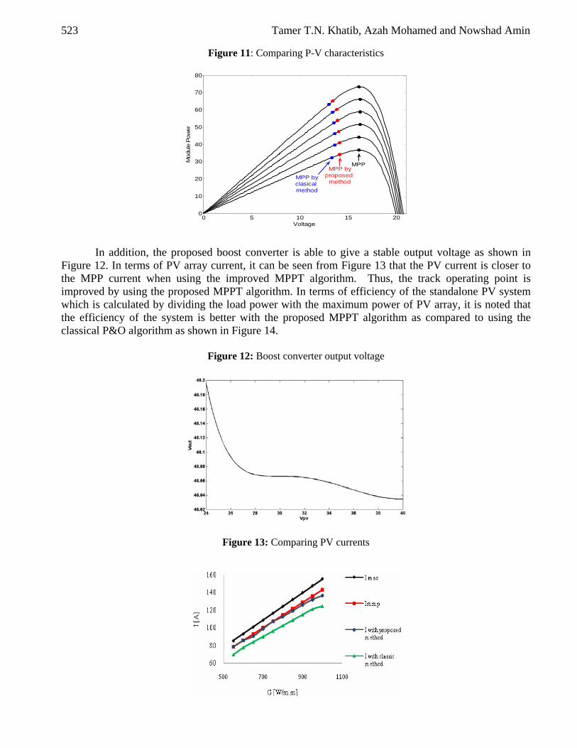
Figure 11 compares the PV array P-V characteristics obtained from using the proposed MPPT algorithm and the classical MPPT P&O algorithm. From this figure, it can be seen that by using the proposed MPPT algorithm, the operating point of PV array is much closer to the MPP compared to the using the classical P&O algorithm.
523 Tamer T.N. Khatib, Azah Mohamed and Nowshad Amin
Figure 11: Comparing P-V characteristics
0 5 10 15 200
10
20
30
40
50
60
70
80
Voltage
Mod
ule
Pow
er
MPPMPP by
proposed method
MPP byclasical method
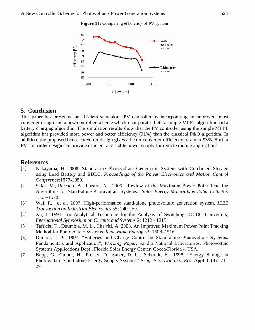
In addition, the proposed boost converter is able to give a stable output voltage as shown in Figure 12. In terms of PV array current, it can be seen from Figure 13 that the PV current is closer to the MPP current when using the improved MPPT algorithm. Thus, the track operating point is improved by using the proposed MPPT algorithm. In terms of efficiency of the standalone PV system which is calculated by dividing the load power with the maximum power of PV array, it is noted that the efficiency of the system is better with the proposed MPPT algorithm as compared to using the classical P&O algorithm as shown in Figure 14.
Figure 12: Boost converter output voltage
Figure 13: Comparing PV currents
A New Controller Scheme for Photovoltaics Power Generation Systems 524
Figure 14: Comparing efficiency of PV system
5. Conclusion This paper has presented an efficient standalone PV controller by incorporating an improved boost converter design and a new controller scheme which incorporates both a simple MPPT algorithm and a battery charging algorithm. The simulation results show that the PV controller using the simple MPPT algorithm has provided more power and better efficiency (91%) than the classical P&O algorithm. In addition, the proposed boost converter design gives a better converter efficiency of about 93%. Such a PV controller design can provide efficient and stable power supply for remote mobile applications. References [1] Nakayama, H. 2008. Stand-alone Photovoltaic Generation System with Combined Storage
using Lead Battery and EDLC. Proceedings of the Power Electronics and Motion Control Conference:1877-1883.
[2] Salas, V., Barrado, A., Lazaro, A. 2006. Review of the Maximum Power Point Tracking Algorithms for Stand-alone Photovoltaic Systems. Solar Energy Materials & Solar Cells 90: 1555–1578.
[3] Wai, R. et al. 2007. High-performance stand-alone photovoltaic generation system. IEEE Transaction on Industrial Electronics 55: 240-250.
[4] Xu, J. 1991. An Analytical Technique for the Analysis of Switching DC-DC Converters, International Symposium on Circuits and Systems 2: 1212 - 1215
[5] Tafticht, T., Doumbia, M. L., Che´riti, A. 2008. An Improved Maximum Power Point Tracking Method for Photovoltaic Systems. Renewable Energy 33: 1508–1516
[6] Dunlop, J. P., 1997. “Batteries and Charge Control in Stand-alone Photovoltaic Systems. Fundamentals and Application”, Working Paper, Sandia National Laboratories, Photovoltaic Systems Applications Dept., Florida Solar Energy Center, Cocoa/Florida -. USA.
[7] Bopp, G., Galber, H., Preiser, D., Sauer, D. U., Schmidt, H., 1998. “Energy Storage in Photovoltaic Stand-alone Energy Supply Systems” Prog. Photovoltaics: Res. Appl. 6 (4):271–291.


