Embed Size (px)
DESCRIPTION
electrical machines
Citation preview

EJ2210 Analysis of Electrical MachinesLecture 3
Oskar WallmarkAssociate Professor, PhD
Laboratory of Electrical Energy Conversion
Royal Institute of Technology
Stockholm, Sweden
May 4, 2012

Outline I
Stator WindingsBasic Winding DataMush WindingsDiamond Windings
Rotor Windings
Insulation Systems

Basic Winding Data
The number of conductors per slots ns can be computed as
ns = int
(
N1cs
qf11
)
.
Here,
N1 =Uf√
2πLDf Bδ
where Uf is the (rms) phase voltage.
Recall also the fundamental winding factor f11:
f11 =1
q
sin(π/6)
sin
(
π
6q
) sinyspπ
6q
where ysp is the pitch length in number of slots.

Mush Windings (sv. plocklinding)
< 700 V, < 450 kW, p=2–4, ≤ 400 mm.

Slot Shapes
Slot a is a “standard slot”.
Slot shape c provides the most copper area but: Corners may not be accurately filled with conductors. The life time of the punching tool may be shorter due to the
small corner radius.

Catalog Geometry
Typical catalog geometry data (semi closed slots):

Slot Contents
Insulated slot area Yis is found as (double layer winding)
Yis = Yis1 + Yis2
Yis1 =π(r − ds)
2
2Yis2 ≈ (h1 − 2ds − dm) (bs1 − 2ds) + (r − bs1/2)(h1 − 2ds − dm)
where h1=hs − hsys − hkil − r .
Slot Contents
The slot fill factor Fs is found as
Fs =Nsπ
(
Np1d2is1 + Np2d
2is2
)
Yis
dis = dcu +∆is
where Ns is the number of conductors per slot, Np1 is thenumber of parallel strands with diameter dis1, dcu is thecopper diameter and ∆is is the double layer thickness of thecopper coating.
The coating increases the copper strand diameter with around5% (2.4 mm) to 7% (0.9 mm).
Theoretical maximum of Fs for round conductors in arectangular slot is Fs=π/4 ≈0.785.
An experienced winder can obtain somewhat higher fill factorsthan what obtained with winding machines.

Coil Dimensions
Figure: Two- and three-cross windings with concentric coils.
Single layer windings are suitable for automatized windingmachines (one phase can be finished before the next phase isinserted).
Single layer mush windings often do not have equal butconcentric coils (saves space and copper and are easier towind).
Three-cross reduces axial length and average coil lengthcompared to two-cross.

Coil Dimensions
Half the average coil length L1:
L1 ≈ L+ π(R1 + R2)/2
R1 = yspτs/2, R2 =(ysp + 2)τs
2
where ysp is the (smallest) coil pitch in slots, τs is the slotpitch (m).

Coil Dimensions
Approximate axial length (one side) of the end winding Lys :
Lys =yspτs2
+
(
q −1
2
)
b
where b the widest slot width (note: slightly different fromeq. (3.6)).
ysp for the innermost (smallest) coil should be used.

Coil Dimensions
Insertion of coils in a small machine with a mush winding.

Coil Dimensions
Brazing of coil ends (left) and impregnation of the winding bysoaking (right).

Diamond Windings (sv. formlinding)
> 700 V, > 500 kW, p > 4, ≥ 400 mm.
Coils manufactured before insertion.
Rectangular strands with larger areas than strands in mushwindings.

Diamond Windings (sv. formlinding)
The diamond winding is most often a double layer winding.
All coils have the same pitch (i.e., not concentric coils).
Often short pitched to reduce impact of 5th and 7th harmonic.

Diamond Windings (sv. formlinding)
One sided axial length Lys and half average coil length L1 tobe estimated.

Diamond Windings (sv. formlinding)
Assuming R1≈R2=R , trigonometry (do it yourself) yields:
Lys = h + Lstraight + τx tanα+ (2R + b)1− sinα
cosα
L1 =2τxcosα
+ 2(2R + b)
(
π/2 − α−1− sinα
cosα
)
+ 2Lstraight + L.

Diamond Windings (sv. formlinding)
Spreading (left) and insulation (right) of a diamond winding.

Diamond Windings (sv. formlinding)
Coil insertion.

Diamond Windings (sv. formlinding)
Slot wedges (left) and braced diamond coil ends (right).

Rotor Windings
Cast Al rotors most common type for up to 400 mm shaftheights.
Slots closed ⇒ prevents Al to come out on the rotor surface,reduces permeance variations but increases slot leakage (lessstarting torque).
Rotor a: Double cage rotor suitable for grid operation (highstarting torque due to high resistance at grid frequency).
Rotor b: Grid operation, lower losses but also lower startingtorque.
Rotor c: Suitable for inverter supply.

Rotor Windings
No insulation in casted rotors. However, the Al oxide layeradds some insulation.
Very high fill factor compared to the stator winding (≈1).
The rotor bars can also be inserted (Al or Cu).
Wound rotors uncommon though used in doubly-fed inductiongenerators (wind turbines).

Rotor Windings
The rotor is often skewed.
Reduces noise and torque ripple.
Single skew by one stator slot pitch most common.
Slightly increased stray losses (due to inter-bar currents).
The stator can also be skewed.

Insulation Systems
The insulation shall:
1. Separate conductors electrically from each other and ground.2. Arrange the E-field distribution so that partial discharges (PD)
do not occur (high voltage machines).3. Mechanically secure the conductors.4. Transport the heat generated by the copper losses to cooler
parts of the machine (Chapter 6).5. Endure handling during manufacturing and installation.6. Withstand thermal stresses during transient and steady state
conditions.
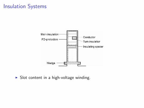
Insulation Systems
Slot content in a high-voltage winding.

Insulation Systems
Class Hot spot temp (C)
A 105E 120B 130F 155H 180
Rule of thumb: Insulation lifetime halved for every 10C riseof temperature.
Often, the temperature rise is given with respect to anambient temperature of 40C.

Partial Discharges (PD)
PD can result in cavities trapping gas inside the insulation.
Occurs when voltage across the cavity exceeds the ignitionvoltage.
Electrical corona discharge transformed into heat.
Small local sparks affecting the material where they occur.

PD Protection (sv. sparglimskydd)
Impossible to fit the winding so that it completely fills the slot.
PD protection made up by thin, low-resistive material most incontact with the stator core.
All the voltage is built up within the insulation ⇒ PD betweenthe coil and the lamination is avoided.

PD Protection (sv. andglimskydd)
Close to the coil ends, large E-fields can arise resulting in PD.
An enamel with voltage dependent resistivity (decreases withapplied voltage) evens out the E-field distribution ⇒ PD isavoided.

Insulation Testing
Resistance between terminal-earth and terminal-terminal ismeasured (dc voltage/dc current).
Healthy insulation ⇒ MΩ–GΩ. Insulation fault ⇒ kΩ.
High voltage (kV) is added for 1 minute at grid frequency (50or 60 Hz).
Resistance between terminal-earth and terminal-terminal ismeasured again.


What Have We Learnt?
We have discussed the basics of mush and diamond windings.
We have reviewed the basics of different rotor slot designs.
We have discussed the basics of insulation systems.
Don’t forget to read about two-speed motors (Dahlanderwinding).

Friendly Reminder
Has your interest in the design of electric machinerydeepened?
EJ2221 Design of Permanent-Magnet Synchronous Machines. 7.5 ECTS credits. Electromagnetic and thermal design. Finite element modeling (Cedrat-Flux).

Friendly Reminder
What about power electronic modulation? EJ2311 Modulation of Power Electronic Converters 6 ECTS credits. Theoretical tools for evaluating different voltage modulation
methods. Two-, three- and multilevel voltage modulation. Impact on electric machinery. Applications overview (HVDC, railway traction).