Embed Size (px)
Citation preview
Lund University / EITF35/ Liang Liu 2015
EITF35: Introduction to Structured
VLSI Design
Part 4.2.1: Learn More …
Liang Liu
1
Lund University / EITF35/ Liang Liu 2015
Outline
Crossing clock domain
Reset, synchronous or asynchronous?
2
Lund University / EITF35/ Liang Liu 2015
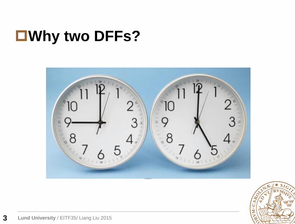
Why two DFFs?
3
Lund University / EITF35/ Liang Liu 2015
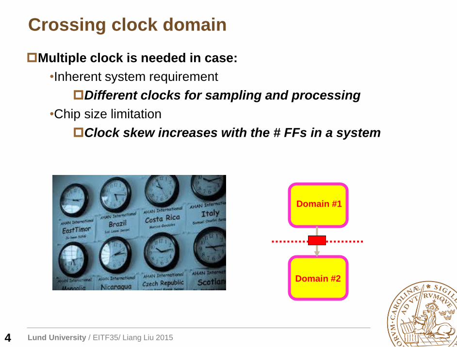
Crossing clock domain
4
Multiple clock is needed in case:
•Inherent system requirement
Different clocks for sampling and processing
•Chip size limitation
Clock skew increases with the # FFs in a system
Domain #1
Domain #2
Lund University / EITF35/ Liang Liu 2015
Multiple Clocks: Problems
5
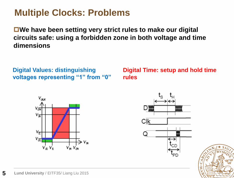
We have been setting very strict rules to make our digital
circuits safe: using a forbidden zone in both voltage and time
dimensions
Digital Values: distinguishing
voltages representing “1” from “0”
Digital Time: setup and hold time
rules
Lund University / EITF35/ Liang Liu 2015
Metastability
6
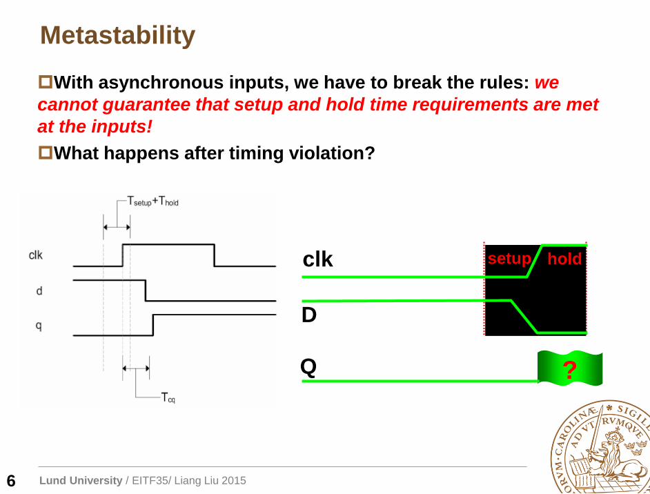
With asynchronous inputs, we have to break the rules: we
cannot guarantee that setup and hold time requirements are met
at the inputs!
What happens after timing violation?
?
D
Q
clk setup hold
Lund University / EITF35/ Liang Liu 2015
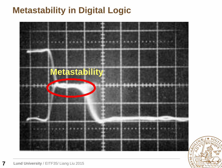
Metastability in Digital Logic
Metastability
7
Lund University / EITF35/ Liang Liu 2015
Mechanical Metastability
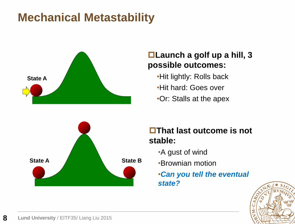
Launch a golf up a hill, 3
possible outcomes:
•Hit lightly: Rolls back
•Hit hard: Goes over
•Or: Stalls at the apex
That last outcome is not
stable:
•A gust of wind
•Brownian motion
•Can you tell the eventual
state?
State A
State A State B
8
Lund University / EITF35/ Liang Liu 2015
Metastability in Digital Logic
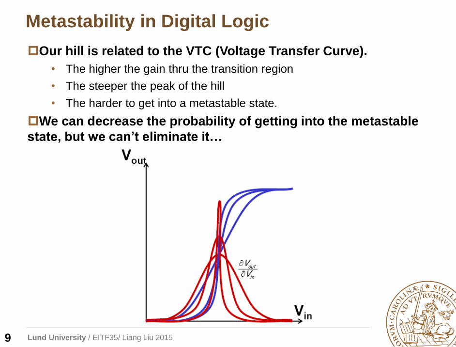
Our hill is related to the VTC (Voltage Transfer Curve).
• The higher the gain thru the transition region
• The steeper the peak of the hill
• The harder to get into a metastable state.
We can decrease the probability of getting into the metastable
state, but we can’t eliminate it…
9
Lund University / EITF35/ Liang Liu 2015
Metastability in Digital Logic
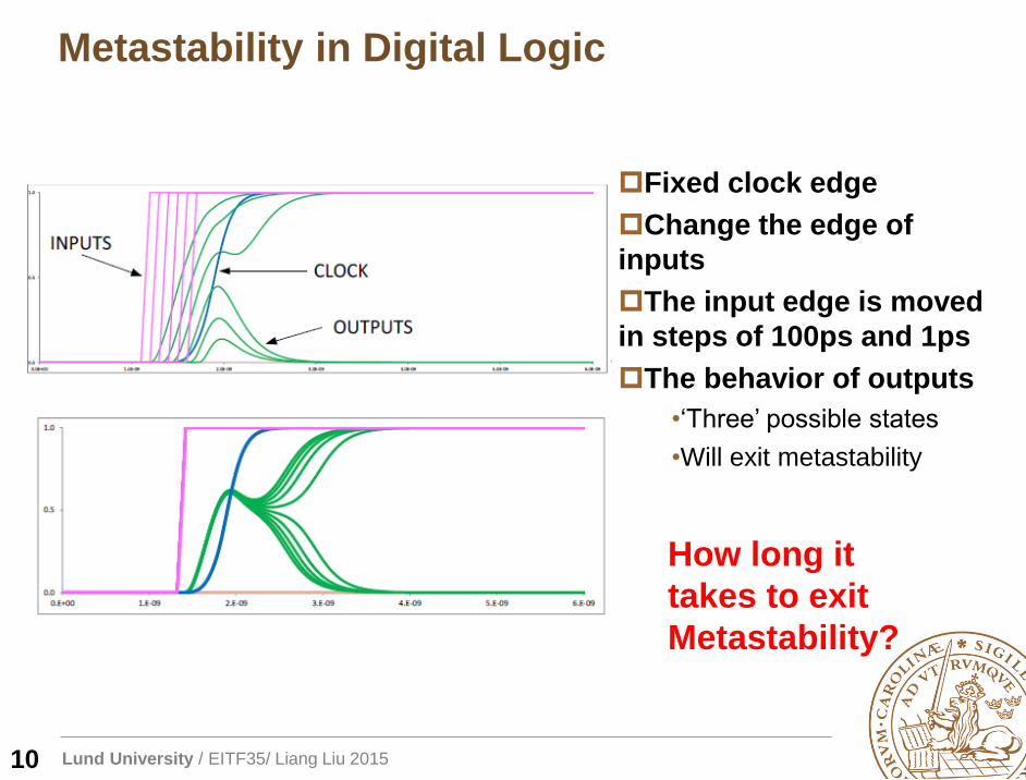
Fixed clock edge
Change the edge of
inputs
The input edge is moved
in steps of 100ps and 1ps
The behavior of outputs
•‘Three’ possible states
•Will exit metastability
How long it
takes to exit
Metastability?
10
Lund University / EITF35/ Liang Liu 2015
Exit Metastability
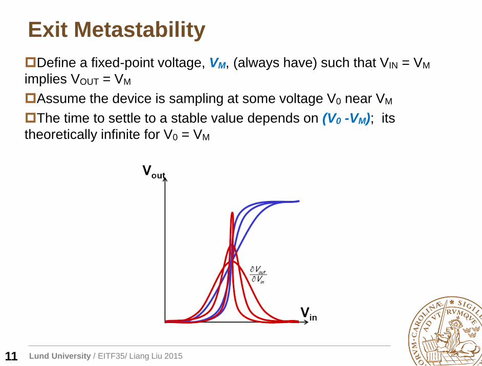
Define a fixed-point voltage, VM, (always have) such that VIN = VM
implies VOUT = VM
Assume the device is sampling at some voltage V0 near VM
The time to settle to a stable value depends on (V0 -VM); its
theoretically infinite for V0 = VM
11
Lund University / EITF35/ Liang Liu 2015
Exit Metastability
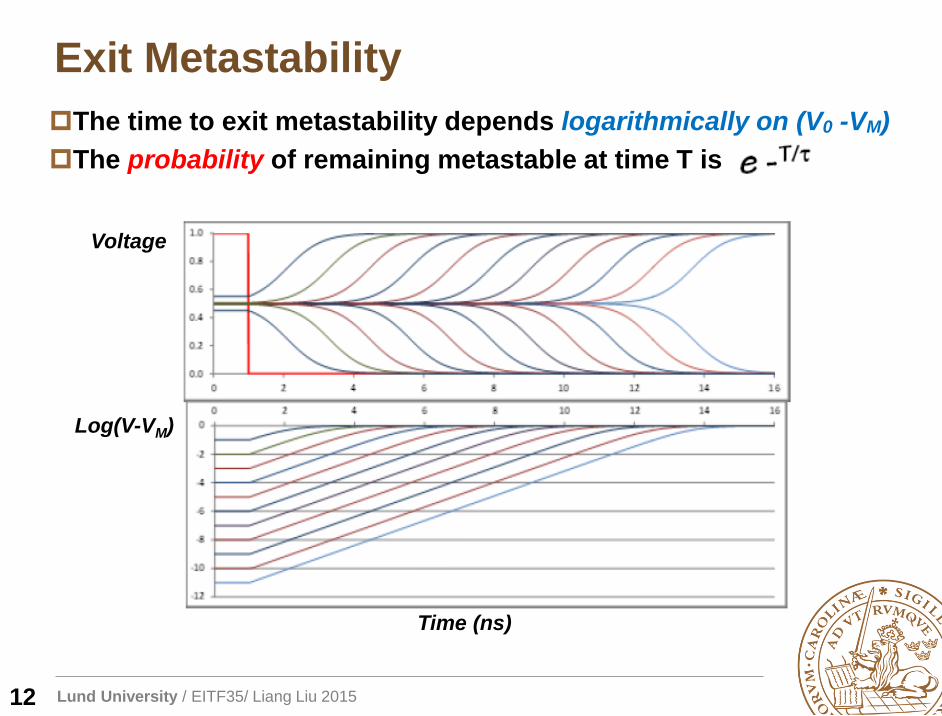
The time to exit metastability depends logarithmically on (V0 -VM)
The probability of remaining metastable at time T is
Time (ns)
Voltage
Log(V-VM)
12
Lund University / EITF35/ Liang Liu 2015
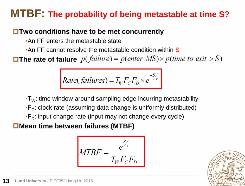
MTBF: The probability of being metastable at time S?
Two conditions have to be met concurrently
•An FF enters the metastable state
•An FF cannot resolve the metastable condition within S
The rate of failure
•TW: time window around sampling edge incurring metastability
•FC: clock rate (assuming data change is uniformly distributed)
•FD: input change rate (input may not change every cycle)
Mean time between failures (MTBF)
13
Lund University / EITF35/ Liang Liu 2015
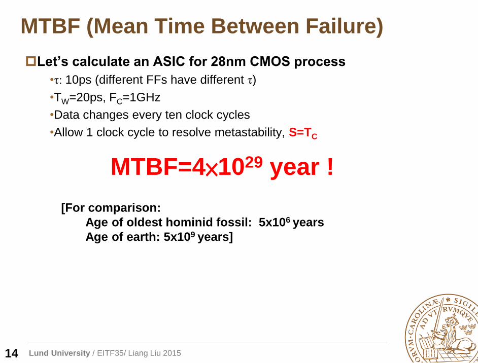
MTBF (Mean Time Between Failure)
Let’s calculate an ASIC for 28nm CMOS process
•τ: 10ps (different FFs have different τ)
•TW=20ps, FC=1GHz
•Data changes every ten clock cycles
•Allow 1 clock cycle to resolve metastability, S=TC
MTBF=4×1029 year !
[For comparison:
Age of oldest hominid fossil: 5x10⁶ years
Age of earth: 5x10⁹ years]
14
Lund University / EITF35/ Liang Liu 2015
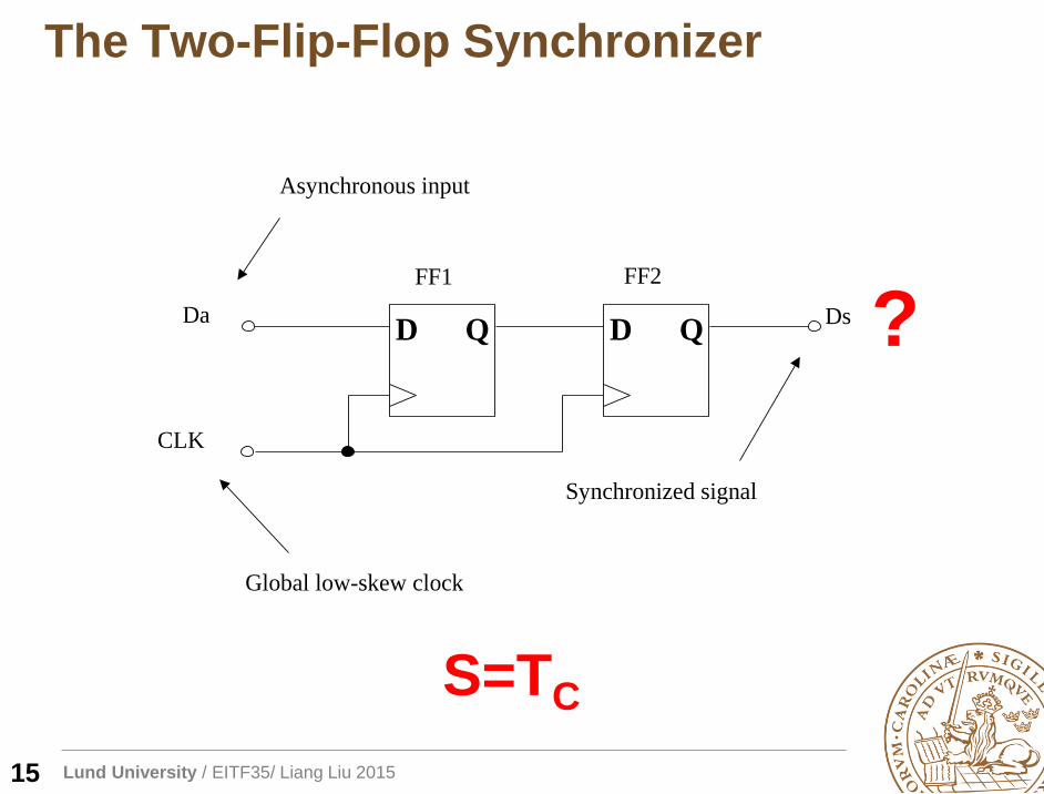
D QD Q
CLK
Da Ds
FF1 FF2
Asynchronous input
Synchronized signal
Global low-skew clock
The Two-Flip-Flop Synchronizer
S=TC
15
?
Lund University / EITF35/ Liang Liu 2015
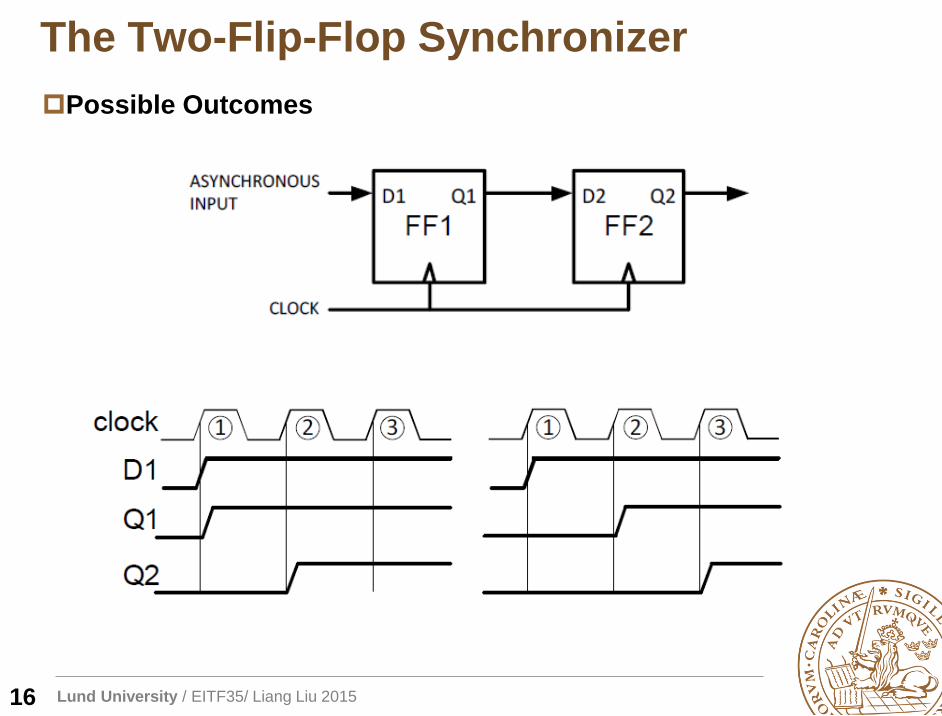
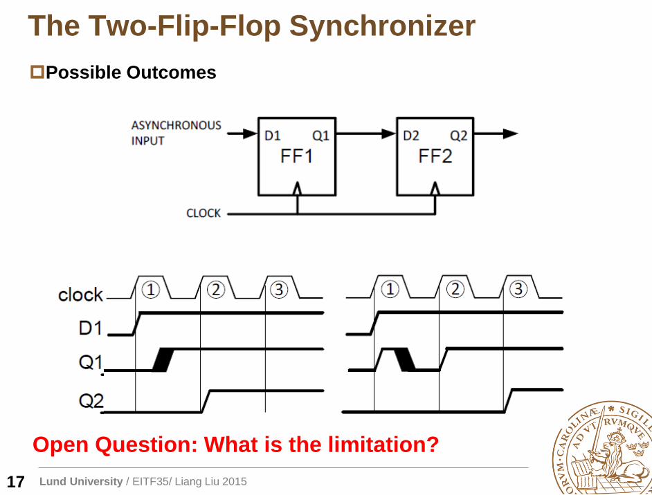
The Two-Flip-Flop Synchronizer
Possible Outcomes
16
Lund University / EITF35/ Liang Liu 2015
The Two-Flip-Flop Synchronizer
Possible Outcomes
17
Open Question: What is the limitation?
Lund University / EITF35/ Liang Liu 2015
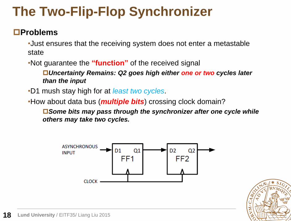
The Two-Flip-Flop Synchronizer
Problems
•Just ensures that the receiving system does not enter a metastable
state
•Not guarantee the “function” of the received signal
Uncertainty Remains: Q2 goes high either one or two cycles later
than the input
•D1 mush stay high for at least two cycles.
•How about data bus (multiple bits) crossing clock domain?
Some bits may pass through the synchronizer after one cycle while
others may take two cycles.
18
Lund University / EITF35/ Liang Liu 2015
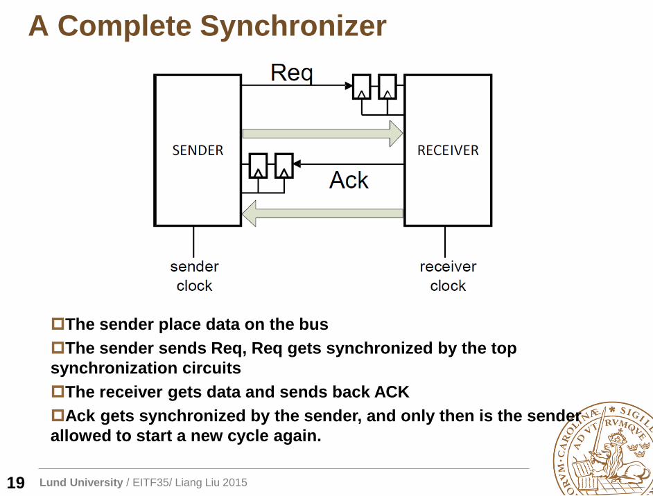
A Complete Synchronizer
The sender place data on the bus
The sender sends Req, Req gets synchronized by the top
synchronization circuits
The receiver gets data and sends back ACK
Ack gets synchronized by the sender, and only then is the sender
allowed to start a new cycle again.
19
Lund University / EITF35/ Liang Liu 2015
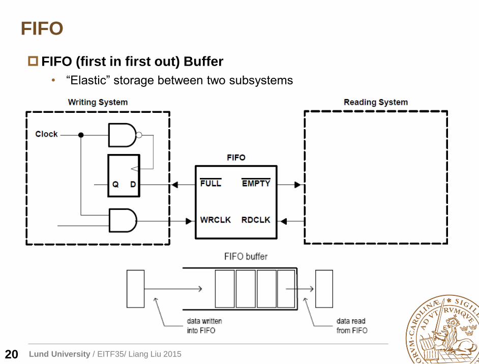
FIFO
FIFO (first in first out) Buffer
• “Elastic” storage between two subsystems
20
Lund University / EITF35/ Liang Liu 2015
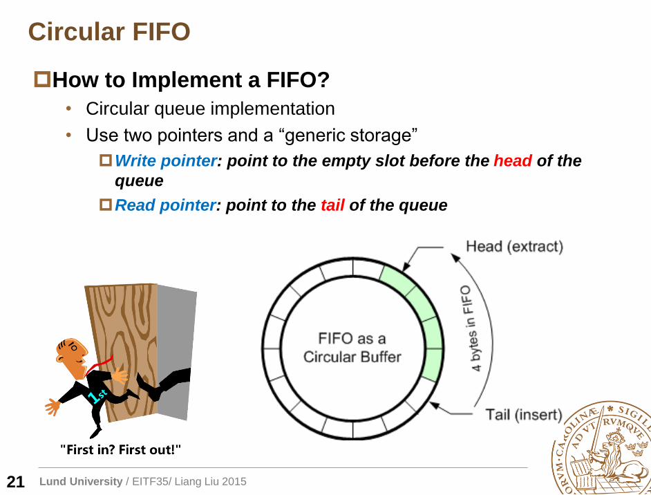
Circular FIFO
How to Implement a FIFO?
• Circular queue implementation
• Use two pointers and a “generic storage”
Write pointer: point to the empty slot before the head of the
queue
Read pointer: point to the tail of the queue
21
Lund University / EITF35/ Liang Liu 201522
(f) 5 6 4
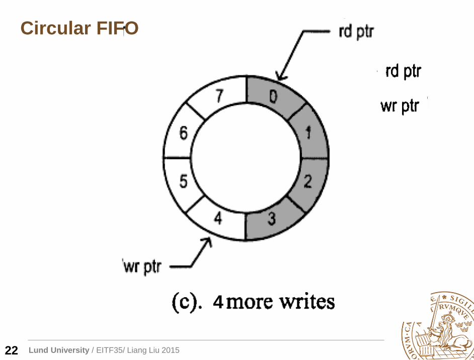
Circular FIFO
Lund University / EITF35/ Liang Liu 2015
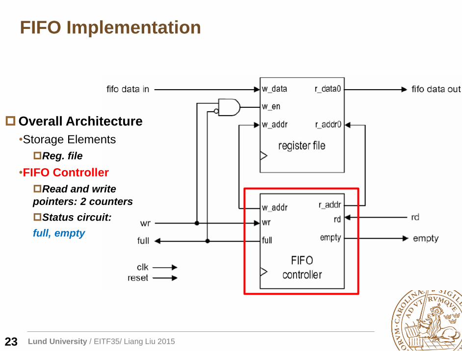
FIFO Implementation
Overall Architecture
•Storage Elements
Reg. file
•FIFO Controller
Read and write
pointers: 2 counters
Status circuit:
full, empty
23
Lund University / EITF35/ Liang Liu 2015
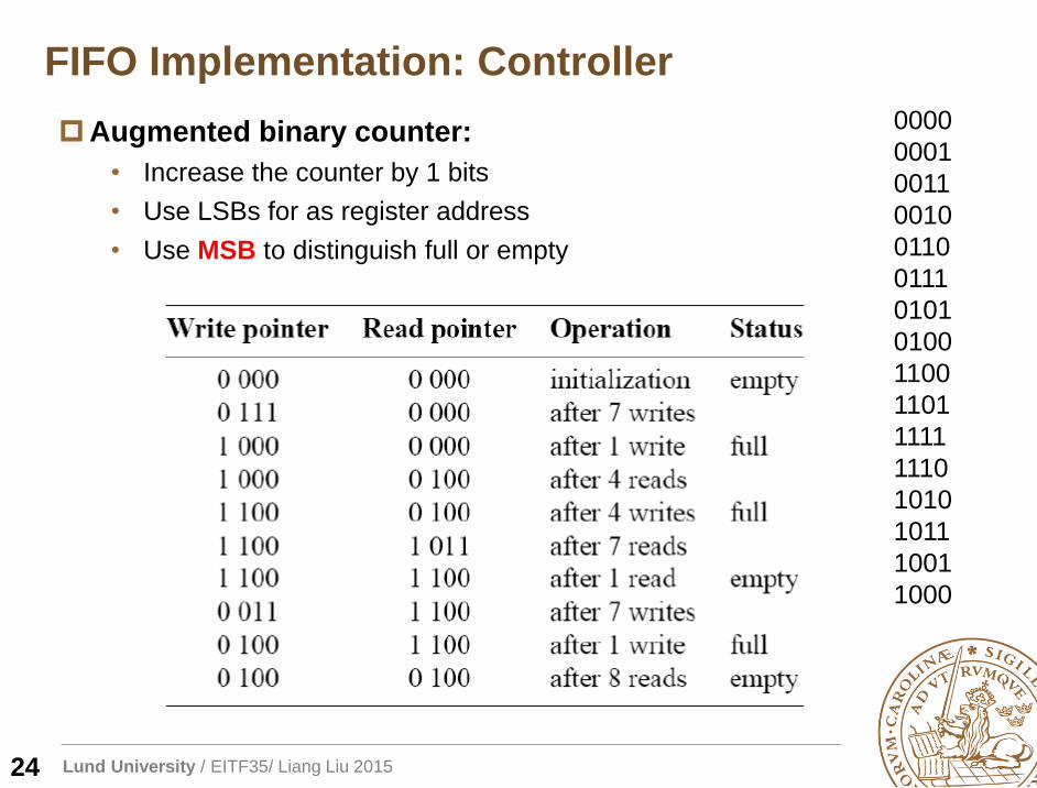
FIFO Implementation: Controller
Augmented binary counter:
• Increase the counter by 1 bits
• Use LSBs for as register address
• Use MSB to distinguish full or empty
24
0000
0001
0011
0010
0110
0111
0101
0100
1100
1101
1111
1110
1010
1011
1001
1000
Lund University / EITF35/ Liang Liu 2015
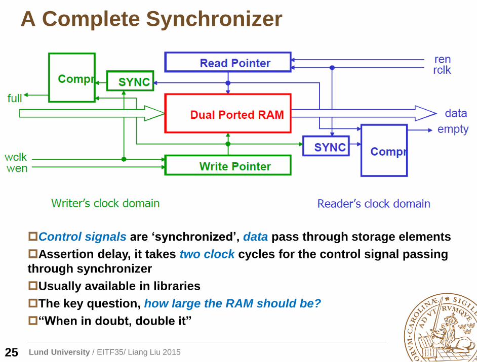
A Complete Synchronizer
Control signals are ‘synchronized’, data pass through storage elements
Assertion delay, it takes two clock cycles for the control signal passing
through synchronizer
Usually available in libraries
The key question, how large the RAM should be?
“When in doubt, double it”
25
Lund University / EITF35/ Liang Liu 2015
Outline
Crossing clock domain
Reset, synchronous or asynchronous?
26
Lund University / EITF35/ Liang Liu 2015
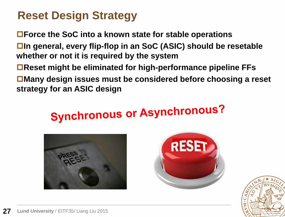
Reset Design Strategy
27
Force the SoC into a known state for stable operations
In general, every flip-flop in an SoC (ASIC) should be resetable
whether or not it is required by the system
Reset might be eliminated for high-performance pipeline FFs
Many design issues must be considered before choosing a reset
strategy for an ASIC design
Lund University / EITF35/ Liang Liu 2015
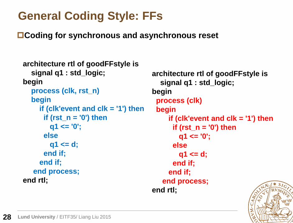
General Coding Style: FFs
28
Coding for synchronous and asynchronous reset
architecture rtl of goodFFstyle is
signal q1 : std_logic;
begin
process (clk, rst_n)
begin
if (clk'event and clk = '1') then
if (rst_n = '0') then
q1 <= '0';
else
q1 <= d;
end if;
end if;
end process;
end rtl;
architecture rtl of goodFFstyle is
signal q1 : std_logic;
begin
process (clk)
begin
if (clk'event and clk = '1') then
if (rst_n = '0') then
q1 <= '0';
else
q1 <= d;
end if;
end if;
end process;
end rtl;
Lund University / EITF35/ Liang Liu 2015
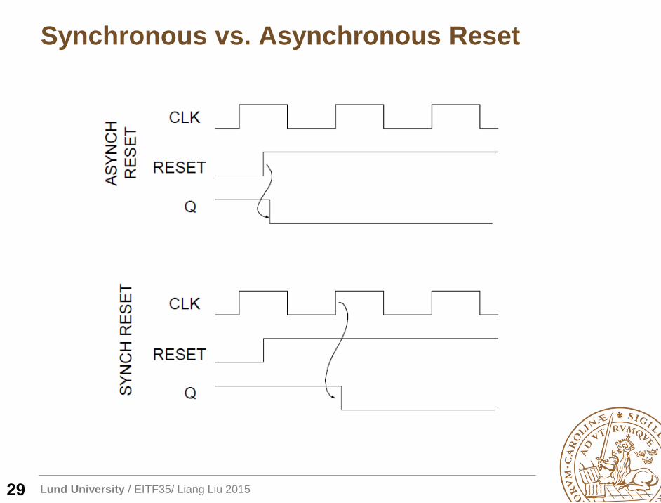
Synchronous vs. Asynchronous Reset
29
Lund University / EITF35/ Liang Liu 2015
Synchronous vs. Asynchronous Reset
30
80% designs using synchronous reset (investigation by
Sunburst Design, Inc)
“we all know that the best way to do resets in an ASIC is to
strictly use synchronous resets”
“asynchronous resets are bad and should be avoided”
There are both advantages and disadvantages to using either
synchronous or asynchronous resets.
The designer must use an approach that is appropriate for
the design.
Lund University / EITF35/ Liang Liu 2015
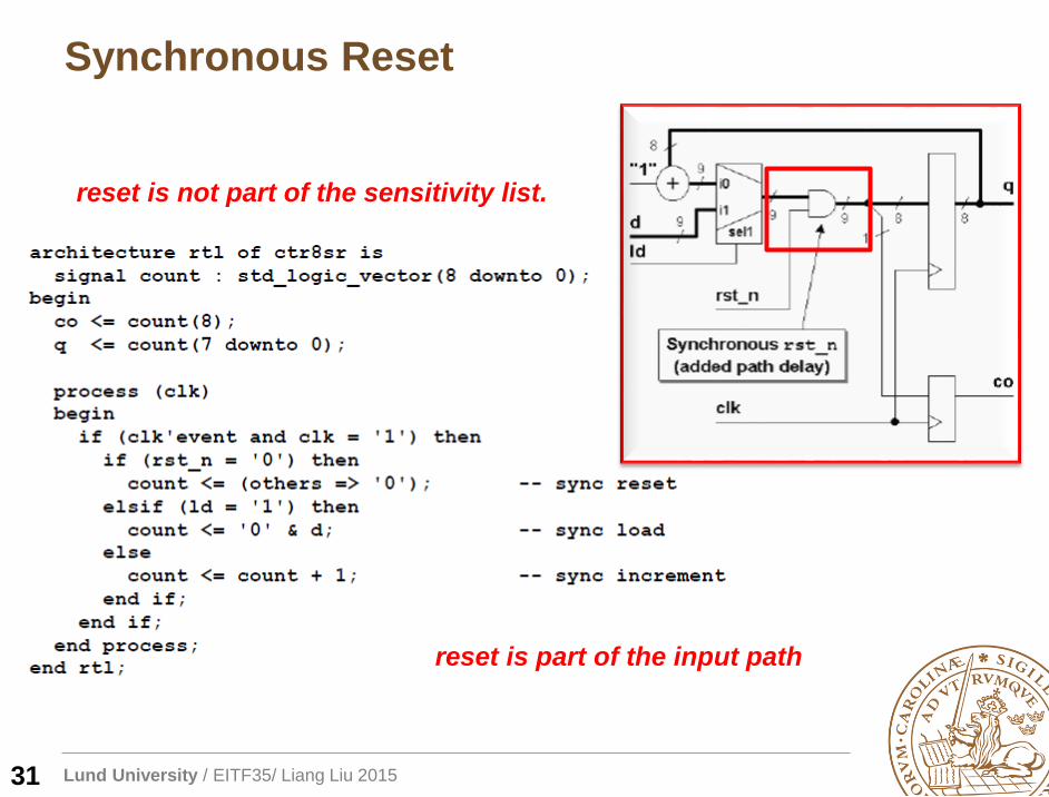
Synchronous Reset
31
reset is not part of the sensitivity list.
reset is part of the input path
Lund University / EITF35/ Liang Liu 2015
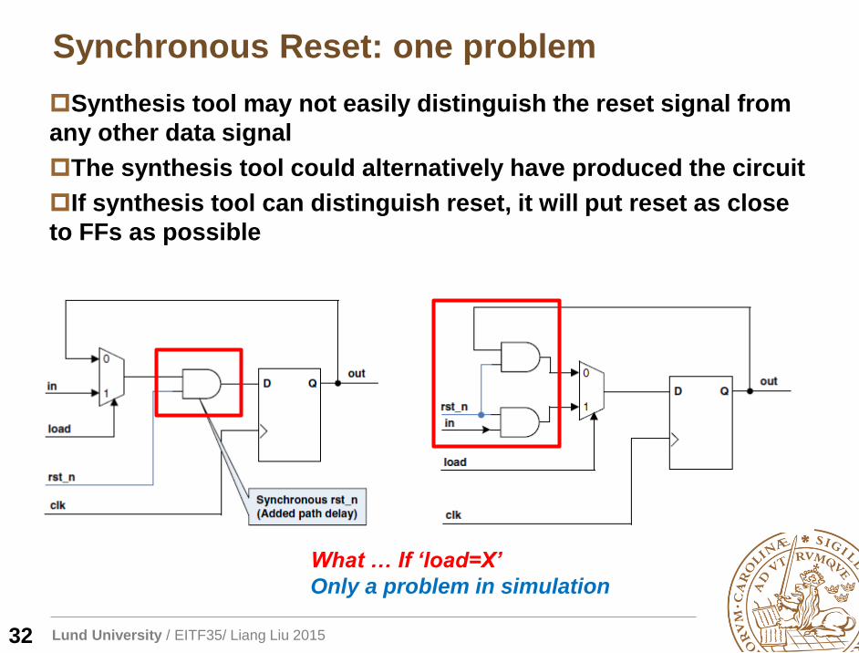
Synchronous Reset: one problem
32
What … If ‘load=X’
Only a problem in simulation
Synthesis tool may not easily distinguish the reset signal from
any other data signal
The synthesis tool could alternatively have produced the circuit
If synthesis tool can distinguish reset, it will put reset as close
to FFs as possible
Lund University / EITF35/ Liang Liu 2015
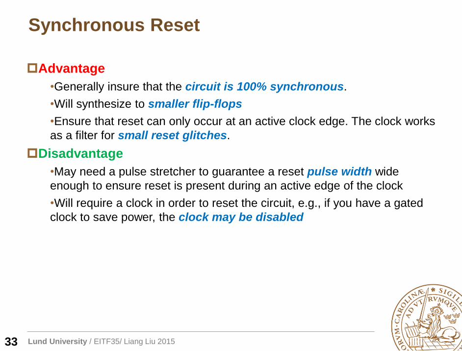
Synchronous Reset
33
Advantage
•Generally insure that the circuit is 100% synchronous.
•Will synthesize to smaller flip-flops
•Ensure that reset can only occur at an active clock edge. The clock works
as a filter for small reset glitches.
Disadvantage
•May need a pulse stretcher to guarantee a reset pulse width wide
enough to ensure reset is present during an active edge of the clock
•Will require a clock in order to reset the circuit, e.g., if you have a gated
clock to save power, the clock may be disabled
Lund University / EITF35/ Liang Liu 2015
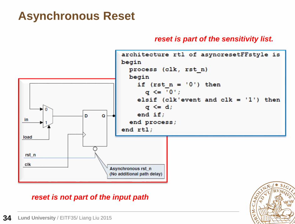
Asynchronous Reset
34
reset is part of the sensitivity list.
reset is not part of the input path
Lund University / EITF35/ Liang Liu 2015
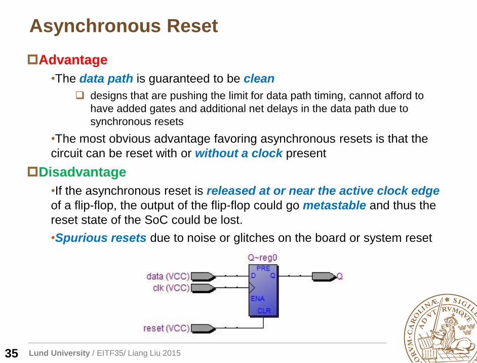
Asynchronous Reset
35
Advantage
•The data path is guaranteed to be clean
designs that are pushing the limit for data path timing, cannot afford to
have added gates and additional net delays in the data path due to
synchronous resets
•The most obvious advantage favoring asynchronous resets is that the
circuit can be reset with or without a clock present
Disadvantage
•If the asynchronous reset is released at or near the active clock edge
of a flip-flop, the output of the flip-flop could go metastable and thus the
reset state of the SoC could be lost.
•Spurious resets due to noise or glitches on the board or system reset
Lund University / EITF35/ Liang Liu 2015
Reset Timing
36
Lund University / EITF35/ Liang Liu 2015
Reset Removal Problem
37
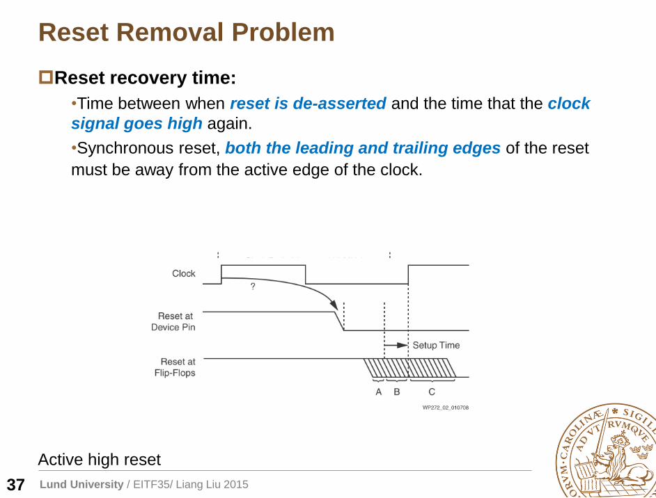
Reset recovery time:
•Time between when reset is de-asserted and the time that the clock
signal goes high again.
•Synchronous reset, both the leading and trailing edges of the reset
must be away from the active edge of the clock.
Active high reset
Lund University / EITF35/ Liang Liu 2015
Reset Removal Problem
38
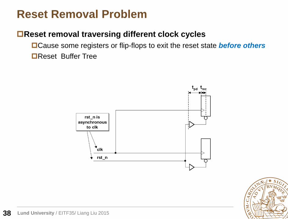
Reset removal traversing different clock cycles
Cause some registers or flip-flops to exit the reset state before others
Reset Buffer Tree
Lund University / EITF35/ Liang Liu 2015
Reset Removal Problem
39
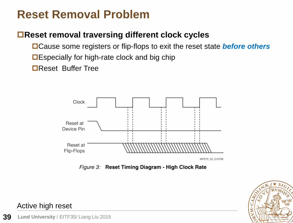
Reset removal traversing different clock cycles
Cause some registers or flip-flops to exit the reset state before others
Especially for high-rate clock and big chip
Reset Buffer Tree
Active high reset
Lund University / EITF35/ Liang Liu 2015
But… Does it really matter?
40
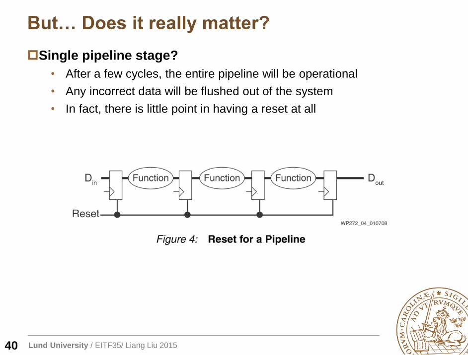
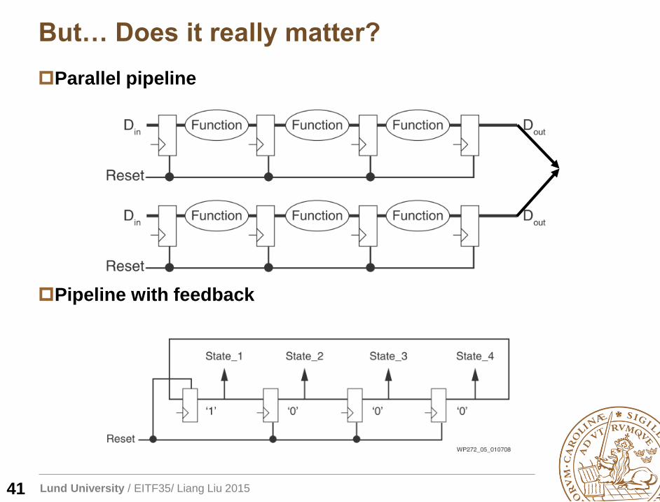
Single pipeline stage?
• After a few cycles, the entire pipeline will be operational
• Any incorrect data will be flushed out of the system
• In fact, there is little point in having a reset at all
Lund University / EITF35/ Liang Liu 2015
But… Does it really matter?
41
Parallel pipeline
Pipeline with feedback
Lund University / EITF35/ Liang Liu 2015
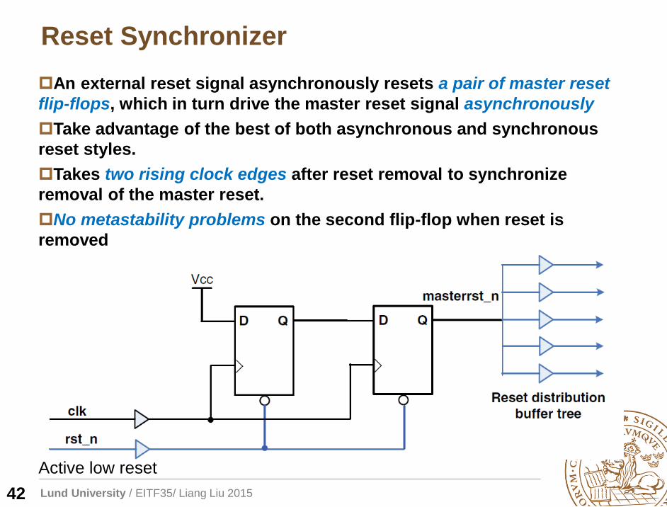
Reset Synchronizer
42
An external reset signal asynchronously resets a pair of master reset
flip-flops, which in turn drive the master reset signal asynchronously
Take advantage of the best of both asynchronous and synchronous
reset styles.
Takes two rising clock edges after reset removal to synchronize
removal of the master reset.
No metastability problems on the second flip-flop when reset is
removed
Active low reset
Lund University / EITF35/ Liang Liu 2015
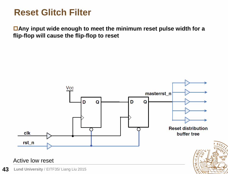
Reset Glitch Filter
43
Any input wide enough to meet the minimum reset pulse width for a
flip-flop will cause the flip-flop to reset
Active low reset
Lund University / EITF35/ Liang Liu 2015
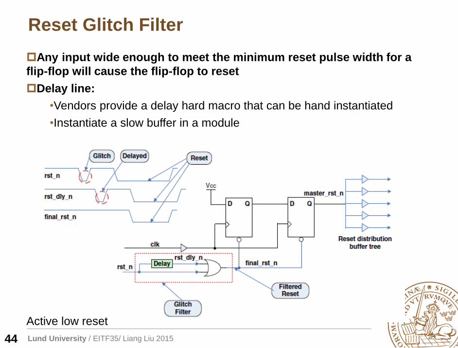
Reset Glitch Filter
44
Any input wide enough to meet the minimum reset pulse width for a
flip-flop will cause the flip-flop to reset
Delay line:
•Vendors provide a delay hard macro that can be hand instantiated
•Instantiate a slow buffer in a module
Active low reset
Lund University / EITF35/ Liang Liu 2015
Xilinx Reset
45
Lund University / EITF35/ Liang Liu 2015
Xilinx Reset: covering 99.99% of cases
46
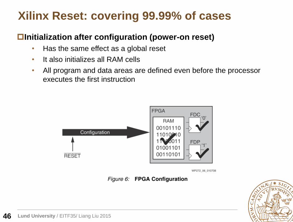
Initialization after configuration (power-on reset)
• Has the same effect as a global reset
• It also initializes all RAM cells
• All program and data areas are defined even before the processor
executes the first instruction
Lund University / EITF35/ Liang Liu 2015
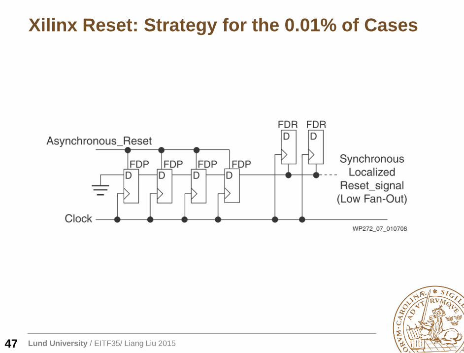
Xilinx Reset: Strategy for the 0.01% of Cases
47
Lund University / EITF35/ Liang Liu 2015
Reference Readings
48
“Synchronous Resets? Asynchronous Resets? I am so
confused! How will I ever know which to use?”
Get your Priorities Right – Make your Design Up to 50% Smaller
http://www.xilinx.com/support/documentation/white_papers/wp275.pdf
Get Smart About Reset: Think Local, Not Global
http://www.xilinx.com/support/documentation/white_pa
pers/wp272.pdf
Simulation and Synthesis Techniques for Asynchronous
FIFO Design
Lund University / EITF35/ Liang Liu 2015
Lecture
49
Erik Larsson
Associate Professor
Sept. 28th Monday (8.15-10.00)
No lecture tomorrow
Design for Test (DFT)
Sept. 29th Tuesday (8.30-10.00)
Igor Tasevski

![GCC internals intro y optimizationesnicolasw/Docencia/CP/gcc_int_intro.pdf · Optimizaciones Back-end Backend: – RTL tree + RTL language + RTL Engine + RTL Compiler [Middle-End]](https://img.pdfslide.us/doc/110x75/5f066be67e708231d417e97b/gcc-internals-intro-y-optimizationes-nicolaswdocenciacpgccintintropdf-optimizaciones.jpg)