Embed Size (px)
Citation preview
Eindhoven University of Technology
MASTER
Generating UML diagrams using feature diagrams for software product line
Liu, X.
Award date:2006
Link to publication
DisclaimerThis document contains a student thesis (bachelor's or master's), as authored by a student at Eindhoven University of Technology. Studenttheses are made available in the TU/e repository upon obtaining the required degree. The grade received is not published on the documentas presented in the repository. The required complexity or quality of research of student theses may vary by program, and the requiredminimum study period may vary in duration.
General rightsCopyright and moral rights for the publications made accessible in the public portal are retained by the authors and/or other copyright ownersand it is a condition of accessing publications that users recognise and abide by the legal requirements associated with these rights.
• Users may download and print one copy of any publication from the public portal for the purpose of private study or research. • You may not further distribute the material or use it for any profit-making activity or commercial gain
Technical University of Eindhoven
Department of Mathematics and Computer Science
Generating UML Diagrams
using Feature Diagrams
for Software Product Line
Master Thesis
Master of Computer Science and Engineering
By
Xin Liu
Supervisor:
M.R.V. Chaudron (TU/e)
Eindhoven, August 2006
2
Foreword
There had never been a project like FeatureUML that gave me so much concentration, so
much stress, and so much pleasure at the same time. The reason that I could think of is
that product line system development is still a pretty young topic, and there are still no
many existing methods which support this kind of development. This attracts me as I was
really curious about if we could find a way to solve the problem.
Well, after seven months work we have got something – FeatureUML. It is only an idea
and a prototype, but could be the start of a possible solution. For this I am really happy
because it gives me a good feeling that I haven’t wasted my time on doing something just
for trying to graduate for my study.
During these seven months, very often I was lost or I just thought that I could not do it. I
was afraid that I could not work out something at the end; I was afraid that I could not
make the prototype… It was my supervisor Michel Chaudron which continually guided
me, pushed me to reach the end. I am really thankful for all the efforts he has put into
helping me finishing my project.
Probably many people would think having a little baby and working at the same time
would be a disaster, but I have a different experience. My just eleven month old lovely
daughter Gina has helped me a great deal to go through the project. For many tiring
nights I was wondering if I still could go on, then I walked into Gina’s room to see her
cute little sleeping face, all my tiredness was simply gone, and I could continue again.
She is truly my angel.
I have to say “thank you” from my heart to my husband Christian. He has been
supportive during my whole master study. Whenever I think that I am just crap and I can
do nothing good, he can always calm me down and bring my confidence back. During
my project period he has been taking care of Gina really a lot, and I hope he can get his
whole week long sleep after my graduation.
At last I give my thanks to professor dr. Mark van den Brand and professor Johan
Lukkien for taking place in my examination board.
3
Abstraction
Software development is going through rapid change all the time. Unlike a few decades
ago we had to create an individual system from scratch when we had a new customer, the
modern development tends to reuse the existing code, components, or products and do
some modification on these existing software assets for each new customer. But how to
make the modification as simple as possible and how to make this software reuse as
effortless as possible is still an unsolved problem.
A product line is a set of software systems that shares a common software architecture
and a set of reusable components. The main characteristic of a product line is that it holds
commonalities for all the members of the family, but also contains variabilities for each
single member of the family. It seems that product line is a candidate solution for the
problem of quick software creation.
Even though the product line concept is not new in other industries, it is still not a widely
accepted concept in software industry. The product line software system development
guideline has been defined only on an abstract level, there are until now still no solid
methods which truly support the process symmetrically and automatically. To find a good
method for this process will still be a research topic for some years.
In this master thesis we give introductions to the concepts of product line and the system
development process. One existing method, PLUS, will also be introduced in this thesis.
PLUS supports part of the product line development process and it does have its
weakness, but it also has its strong points which we can learn from.
We will also propose a new method – FeatureUML which supports part of the product
line software development. This new method uses feature diagrams to hold the features in
the feature model, and the UML model is slightly modified to hold mapping information
between UML elements and features. The feature model can be configured for a single
member of the product line; with this configuration we can also process a domain UML
model to yield a specialized UML model for a single member. A prototype has been
made to show the idea of FeatureUML and in this thesis we will also use a few examples
to show how FeatureUML works.
4
Contents
1 Introduction................................................................................................................. 6
2 Product Line Software Systems .................................................................................. 8
2.1 Introduction......................................................................................................... 8
2.2 Process ................................................................................................................ 8
2.3 Modeling Requirements – Feature Modeling ................................................... 10
2.3.1 Feature Diagram........................................................................................ 11
2.3.2 Expressing Commonality in Feature Diagrams ........................................ 12
2.3.3 Expressing Variability in Feature Diagrams............................................. 13
2.4 Modeling Design Variability ............................................................................ 13
2.5 UML.................................................................................................................. 13
2.5.1 UML in Product Line Software Design - PLUS....................................... 14
2.5.2 Extended UML Annotation in PLUS........................................................ 15
2.5.3 The Strength and Weakness of PLUS Method ......................................... 17
3 FeatureUML Method ................................................................................................ 19
3.1 Problems FeatureUML Addresses .................................................................... 19
3.2 Product Line Process in FeatureUML............................................................... 19
3.2.1 Domain Engineering ................................................................................. 20
3.2.2 Application Engineering ........................................................................... 21
4 Feature and UML Modeling in FeatureUML Tool................................................... 23
4.1 Feature Modeling .............................................................................................. 23
4.1.1 Feature Types............................................................................................ 23
4.1.2 Feature Cardinality.................................................................................... 24
4.1.3 Feature Dependency.................................................................................. 25
4.2 UML Modeling ................................................................................................. 27
4.2.1 UML Diagram Feature Annotation........................................................... 27
4.2.2 UML Element Types................................................................................. 28
4.3 Feature Diagram Configuration ........................................................................ 31
4.4 UML Model Processing.................................................................................... 33
4.4.1 Rules ......................................................................................................... 33
4.4.2 Processes ................................................................................................... 34
5 FeatureUML Tool ..................................................................................................... 35
5.1 General Goal ..................................................................................................... 35
5.2 Tool Requirements............................................................................................ 35
5.2.1 Environment Description .......................................................................... 35
5.2.2 Required Functionalities ........................................................................... 36
5.3 Tool Design....................................................................................................... 37
5.3.1 Data Structure Analysis ............................................................................ 38
5.3.2 Use Cases .................................................................................................. 38
5.3.3 Architecture............................................................................................... 39
5.3.4 Static Model – Packages and Classes ....................................................... 40
5.3.5 Dynamic Model – Sequence Diagrams..................................................... 47
5.4 Tool Implementation......................................................................................... 52
5.4.1 Source Code .............................................................................................. 52
5.4.2 File Structure............................................................................................. 52
5
6 Case Study – Navigation System.............................................................................. 54
6.1 Variation Points of Navigation System............................................................. 54
6.2 Feature Diagram of Navigation System............................................................ 55
6.3 UML Model of Navigation System .................................................................. 57
6.3.1 Class Diagram........................................................................................... 57
6.3.2 Sequence Diagram “Set Voice Guide” ..................................................... 58
6.3.3 Sequence Diagram “View Map”............................................................... 59
6.3.4 Sequence Diagram “Generate Route”....................................................... 59
6.3.5 Mapping List ............................................................................................. 61
6.4 Configurations and UML Model Processing .................................................... 62
6.4.1 Configuration 1 ......................................................................................... 62
6.4.2 Configuration 2 ......................................................................................... 64
7 Conclusion ................................................................................................................ 68
8 Future Works ............................................................................................................ 69
8.1 Feature Diagram................................................................................................ 69
8.2 Feature-UML Element Mapping/Processing .................................................... 69
8.3 Product Line Software System Process ............................................................ 70
9 References................................................................................................................. 71
6
1 Introduction
The software development process has been changing rapidly in the last few decades. The
industry and business market have put their hope in the productivity, quality, and
maintainability in the software systems in order to prove their service. The traditional
way of developing an individual system from scratch cannot satisfy these demands any
longer.
Software industry has gone through a few major changes trying to fulfill the requirements
from software systems. The fist attempt made was to create an individual system rapidly,
and then to create variations for different customs when the new requirements came in.
This process did improve the speed of the software development process at the beginning.
But the more variations are made, the more difficult we can guarantee the quality of the
software, and the more difficult we can keep a good maintenance. The reason for this is
creating variations on individual systems takes continual investment in understanding
new requirements, and in redesign, recoding and retesting. Currently the software
industry is going through the second change, and that is to create product lines and
families of systems. In this new approach we invest in understanding new requirements
and rapidly creating new family members with little or no redesign and recoding and with
reduced retesting.
Product line software engineering involves two types of activities. First the common
aspects and the predicted variability of a product line are carefully pre-analyzed and well
documented in a systematic way with the goal of maximizing the reuse potential. This
process is often called domain engineering. Secondly individual systems are built by
using the common aspects and some variation features from the domain model for
different customers with different requirements for these individual systems. This process
is often called application engineering.
In the product line software process one of the most challenging aspects is variability
management. Variability management requires methods not only to record the variability
in a systematic way, but also to enable the configuring of the variability of the product
line in order to create individual systems. There are already several methods proposed for
recording the variations of the product line. With these methods the system common
aspects and variabilities can be documented systematically, but when creating a single
product, a lot of handwork is still required to configure the assets in the domain model.
So in general the methods proposed vary often fail to ease the configuration of the
product line.
In this thesis we propose a product line software design variability enabling method by
using feature diagram. With this method it is also possible to configure the product line
design UML model to generate new UML models for individual systems. A prototype
FeatureUML has been built and tested using a case study of Navigation System. The
initial case study has shown us that this method can reduce more than 80% of the time
and effort which is spent on creating individual systems. As the UML model for each

7
single member of the product line is generated and we can hardly make any mistakes in
the generating process, so the quality of the generated UML model is also improved.
This Thesis is structured as follows. Chapter 2 gives an introduction to product line
software systems, the feature diagram, UML diagrams and the usage of feature diagram
and UML diagrams in product line software design. Chapter 3 introduces the
FeatureUML method. Chapter 4 explains how FeatureUML tool realizes the method.
Chapter 5 focuses on the implementation of the FeatureUML tool. In chapter 6 we give a
small case study of Navigation System to show how this method can be used in the real
life. Chapter 7 concludes the study of this method. There are quite a lot of further
research studies which can be done on this method, and these future works are listed in
chapter 8.
8
2 Product Line Software Systems
2.1 Introduction
A software product line consists of a family of software systems that have some common
functionality and some variable functionality. To take advantage of the common
functionality, reusable assets (such as requirements, designs, components, and so on) are
developed, which can be reused by different members of the family [Gomaa 2004].
The idea of a product line is not new. A modern example of product line comes from the
airline industry, with the European Airbus A-318, A-319, A-320, and A-321 airplane,
which share common product feature, including jet engines, navigation equipment and
communication equipment [Clements and Northrop 2002].
The traditional process of software development is to develop single systems – that is, to
develop each system individually. For software product lines, the development approach
is broadened to consider a family of software systems. This approach involves analyzing
what features (functional requirements) of the software family are common, what features
are optional, and what features are alternatives. After the feature analysis, the goal is to
design a software architecture for the product line, which has common components,
(required by all members of the family), optional components (required by only some
members of the family), and variant components (different versions of which are required
by different members of the family). To model and design families of systems, the
analysis and design concepts for single product systems need to be extended to support
software product lines.
2.2 Process
In the product line software development process the software engineer’s role is split into
two parts: the domain engineer, who defines a family and creates the production facilities
for the family, and the application engineer, who uses the production facilities to create
new family members. Correspondingly, the two parts of the approach are known as
domain engineering and application engineering. One of the well known process method
is Family-Oriented Abstraction, Specification, and Translation (FAST), and this process
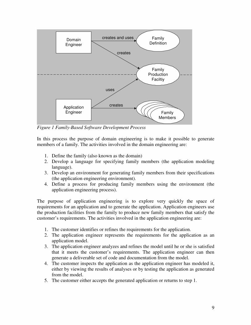
is depicted in Figure 1 [Weiss, D., Lai, C. 1999].
9
DomainEngineer
Family
Definition
FamilyProduction
Faciltiy
Family
Members
ApplicationEngineer
creates and uses
creates
creates
uses
Figure 1 Family-Based Software Development Process
In this process the purpose of domain engineering is to make it possible to generate
members of a family. The activities involved in the domain engineering are:
1. Define the family (also known as the domain)
2. Develop a language for specifying family members (the application modeling
language).
3. Develop an environment for generating family members from their specifications
(the application engineering environment).
4. Define a process for producing family members using the environment (the
application engineering process).
The purpose of application engineering is to explore very quickly the space of
requirements for an application and to generate the application. Application engineers use
the production facilities from the family to produce new family members that satisfy the
customer’s requirements. The activities involved in the application engineering are:
1. The customer identifies or refines the requirements for the application.
2. The application engineer represents the requirements for the application as an
application model.
3. The application engineer analyzes and refines the model until he or she is satisfied
that it meets the customer’s requirements. The application engineer can then
generate a deliverable set of code and documentation from the model.
4. The customer inspects the application as the application engineer has modeled it,
either by viewing the results of analyses or by testing the application as generated
from the model.
5. The customer either accepts the generated application or returns to step 1.
10
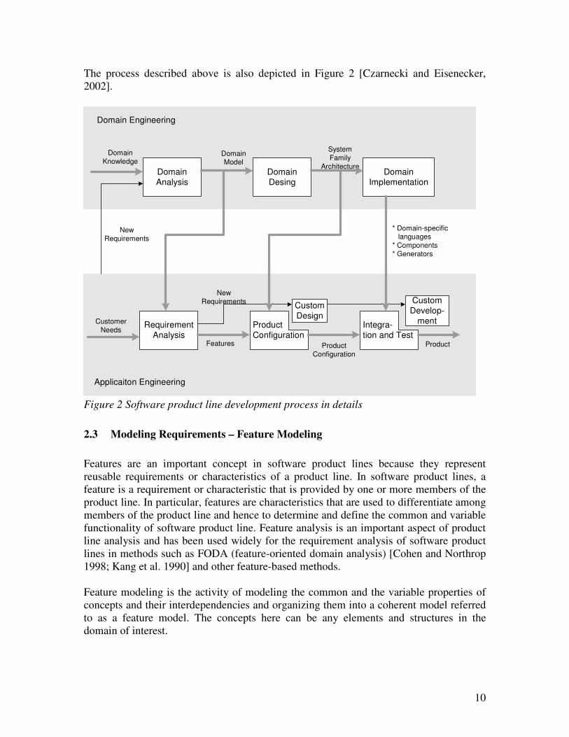
The process described above is also depicted in Figure 2 [Czarnecki and Eisenecker,
2002].
Domain
Analysis
Domain
Desing
Domain
Implementation
Domain Engineering
Domain
KnowledgeDomainModel
System
Family
Architecture
Requirement
Analysis
Customer
Needs
New
Requirements
Product
Configuration
Features
Custom
DesignProduct
Configuration
Integra-
tion and Test
Custom
Develop-
ment
Product
New
Requirements
* Domain-specific languages
* Components
* Generators
Applicaiton Engineering
Figure 2 Software product line development process in details
2.3 Modeling Requirements – Feature Modeling
Features are an important concept in software product lines because they represent
reusable requirements or characteristics of a product line. In software product lines, a
feature is a requirement or characteristic that is provided by one or more members of the
product line. In particular, features are characteristics that are used to differentiate among
members of the product line and hence to determine and define the common and variable
functionality of software product line. Feature analysis is an important aspect of product
line analysis and has been used widely for the requirement analysis of software product
lines in methods such as FODA (feature-oriented domain analysis) [Cohen and Northrop
1998; Kang et al. 1990] and other feature-based methods.
Feature modeling is the activity of modeling the common and the variable properties of
concepts and their interdependencies and organizing them into a coherent model referred
to as a feature model. The concepts here can be any elements and structures in the
domain of interest.
11
A feature model consist of a feature diagram and some additional information, such as
short semantic descriptions of each feature, rationales for each feature, stakeholders and
client programs interested in each feature, examples of systems with a given feature,
constraints, default dependency rules, availability sites, binding modes, and priorities.
2.3.1 Feature Diagram
2.3.1.1 Features
In a feature diagram the root node represents a concept; all other nodes represent the
common and variable properties of this concept. The features in a feature diagram can be
divided into three categories: mandatory, alternative and optional features. The rules
concerning the features are as following:
� Mandatory feature: a mandatory feature is included in the description of a concept
instance if and only if its parent is included in the description of the instance. For
example, if the parent of a mandatory feature is optional and not included in the
instance description, the mandatory feature cannot be part of the description.
� Optional feature: an optional feature may be included in the description of a
concept instance if and only its parent is included in the description. In other
words, if the parent is included, the optional feature may be included or not, and if
the parent is not included, the optional feature cannot be included.
� Alternative feature: if the parent of a set of alternative features is included in the
description of a concept instance, then exactly one feature from this set of
alternative feature is included in the descriptions.
C
f1
f4
f3f2
f5 f6 f8f7
Legenda
mandatory feature
optional feature
alternative feature
C concept
f feature
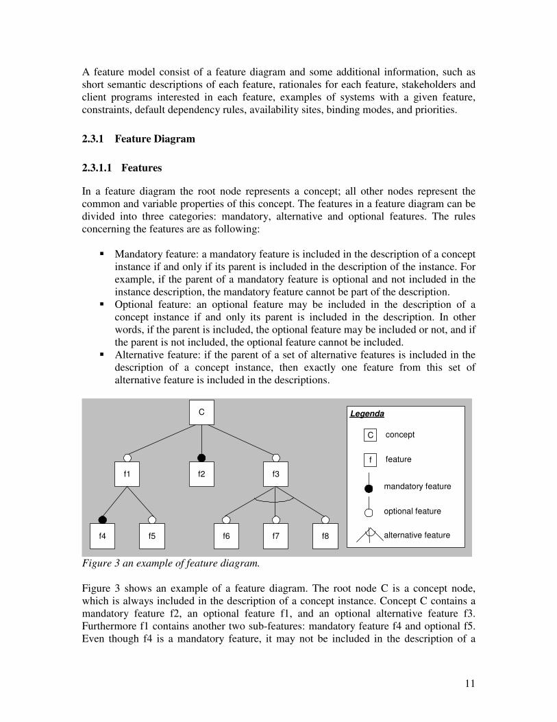
Figure 3 an example of feature diagram.
Figure 3 shows an example of a feature diagram. The root node C is a concept node,
which is always included in the description of a concept instance. Concept C contains a
mandatory feature f2, an optional feature f1, and an optional alternative feature f3.
Furthermore f1 contains another two sub-features: mandatory feature f4 and optional f5.
Even though f4 is a mandatory feature, it may not be included in the description of a
12
concept instance when its parent f1 is not included. Alternative feature f3 contains
another three features: f6, f7 and f8. If f3 is included in the description of a concept
instance, then only one of the feature f6, f7 and f8 will be included.
2.3.1.2 Feature Cardinality
We extend the features with cardinalities in the feature diagrams. In [Czarnecki, 2004]
the feature cardinalities are divided into two types:
1. Feature cardinalities
Features can be annotated with cardinalities, such as [1..∗] or [3..3]. Mandatory
and optional features can be considered special cases of features with the
cardinalities [1...1] and [0...1], respectively.
2. Group and groups cardinalities
Alternative features in the FODA annotation can be viewed as a grouping
mechanism. The concept of groups was further generalized in [Riebisch, 2002] as
a set of features annotated with a cardinality specifying an interval of how many
features can be selected from that set.
2.3.1.3 Feature Dependency
In a feature diagram we can also define the relationships between features from this
feature diagram. These relationships between features are called feature dependencies.
The most common types of feature dependencies are:
1. Require
If a require relation is defined between two features A and B as “A requires B”,
then whenever A is present in the configuration of a feature diagram, B must also
be present in the configuration. But vice versa does the presence of feature B say
nothing about the presence of feature A.
2. Exclude
If an exclude relation is defined between two features A and B as “A excludes B”,
then whenever A is present in the configuration of a feature diagram, B must not
be present in the configuration. Vice versa is also valid, so “A excludes B” means
also “B excludes A”.
2.3.2 Expressing Commonality in Feature Diagrams
The mandatory features presented in a feature diagrams can be further categorized into
two types: common features and common sub-features.
A common feature of a concept is a feature present in all instances of a concept. All
mandatory features which are direct children of concept are common features. Also each
13
mandatory feature, whose parent is a common feature, is a common feature. Thus we can
conclude that a common feature is always present in the description of a concept instance.
A common sub-feature f1 is a child feature of another feature f, which is present in all
instances of a concept where f itself is also present. All direct mandatory sub-features of
f1 are also common sub-features of f. A sub-feature of f is common if it is mandatory and
there is a path of mandatory features connecting the sub-feature and f.
2.3.3 Expressing Variability in Feature Diagrams
Variability in feature diagrams is expressed using optional, alternative and optional
alternative features. These features are also called variable features. The nodes to which
variable features are attached are referred to as variation points. A variation point is
where a product family member might differ from other members.
2.4 Modeling Design Variability
Techniques for modeling variability in design include modeling variability using
parameterization, modeling variability using information hiding, and modeling variability
using inheritance. [Gomaa and Webber 2004]. Each of these techniques has some
strength and weakness. In most product lines, a combination of all three approaches is
needed. The object-oriented approach to software development helps by supporting all
three of these approaches to modeling variability. With the proliferation of annotations
and methods for the object-oriented analysis and design of software applications, the
Unified Modeling Language (UML) was developed to provide a standardized annotation
for describing object-oriented models.
2.5 UML
Modern object-oriented analysis and design methods are model-based and use a
combination of use case modeling, static modeling, state machine modeling, and object
interaction modeling. Almost all modern object-oriented methods use the UML
annotation for describing software requirements, analysis and design models [Booch et al.
2005; Fowler 2004; Rumbaugh et al. 2005].
In use case modeling, the functional requirements of the system are defined in terms of
use cases and actors. Static modeling provides a structural view of the system. Classes are
defined in terms of their attributes, as well as their relationships with other classes.
Dynamic modeling provides a behavioral view of the system. The use cases are realized
to show the interaction among participating object. Object interaction diagrams are
developed to show how objects communicate with each other to realize the use case. The
state-dependent aspects of the system are defined with statecharts.
An object-oriented analysis and design method for software product lines needs to extend
single-system analysis and design concepts to model product lines, in particular to model
14
the commonality and variability in the product line, and to extend the UML annotation to
describe this commonality and variability.
2.5.1 UML in Product Line Software Design - PLUS
PLUS (Product Line UML-Based Software Engineering) [Gomaa 2004] is a UML-based
software design method that extends the UML-based modeling methods for single
systems to address software product lines.
In the PLUS method the activities of modeling a product line system are divided into
three phases: requirements modeling, analysis modeling, and design modeling.
In requirements modeling phase, the following activities are involved:
1. Product line scoping
At a high level, the following aspects of the product line are determined: its
functionality, the degree of commonality and variability, and the likely number of
product line members.
2. Use case modeling
Actors and use cases are defined, and the functional requirements of the product
line are specified in terms of those use cases of actors. Product line commonality
is determined by the development of kernel use cases. Product line variability is
determined by the development of optional and alternative use cases, and by the
identification of variation points within use cases.
3. Feature modeling
Software product line commonality is characterized by kernel features; product
line variability is characterized by optional an alternative features. Features can be
identified from the use cases determined during use case modeling.
In the analysis modeling phase the following activities are involved:
1. Static modeling
A problem-specific static model is defined. The emphasis of static modeling is on
the information modeling of real world classes in the problem domain – in
particular, entity classes and external classes.
2. Object structuring
The objects – Kernel, optional, and alternative – that participate in each use case
are determined. Object structuring criteria are provided to help determine the
objects, which can be entity objects, interface objects, control objects, and
application logic objects.
3. Dynamic modeling
15
The use cases from the use case model are realized to show the interaction among
the objects participating in each kernel, optional and alternative use case.
Communication diagrams or sequence diagrams are developed to show how
objects interact to execute the use case.
4. Finite state machine modeling
The state-dependent aspects of the product line are defined by means of
hierarchical statecharts. Each state-dependent control object is defined in terms of
its constituent statechart. For state dependent object interactions, the interactions
among the state-dependent control objects and the statecharts they execute need to
be modeled explicitly.
5. Feature/class dependency analysis
This step is used to determine what classes from the analysis model are needed to
realize the features from the feature model.
For every feature in the software product line, certain classes realize the
functionality specified by the feature. A common feature is provided by every
member of the product line, the classes that support or realize a common feature
are always kernel classes. Because common features are provided by every
member of the product line, it follows that kernel classes are always present in all
product line member. If an optional or alternative feature is selected for a given
member of the product line, then the optional or variant classes that realize this
feature are also selected.
In the design modeling phase the solution domain is considered. The goal is to develop a
component-based software architecture for the product line. To create the product line
architecture, developers consider what software architectural patterns should provide its
foundation.
2.5.2 Extended UML Annotation in PLUS
In these sections we will use a few examples to show how features are represented in
PLUS UML models.
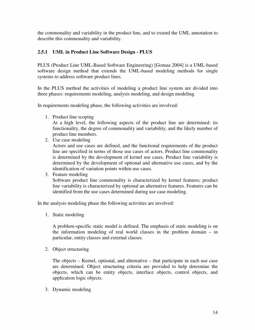
Figure 4 depicts a use case example in PLUS. In this use case there is a kernel use case
“Validate PIN” which correspond to a mandatory feature in a bank product line, and the
mandatory character of this feature is indicated by the stereo type <<kernel>> annotation.
“Validate PIN” includes another three kernel use cases “Withdraw Funds”, “Query
Account”, “Transfer Funds”, and another two optional use cases “Deposit Funds” and
“Print Statement”. The optional features are notated using <<optional>> stereo type.
Whether these two optional use cases are present in one of the Bank system member is
determined by the evaluation expression marked on the arcs with annotation [deposit
option], [ministatement option] respectively.
16
<<kernel>>Validate PIN
<<kernel>>Withdraw Funds
<<optional>>Print Statement
<<optional>>Deposit Funds
<<kernel>>Transfer Funds
<<kernel>>Query Account
<<include>>
<<include>>
<<include>>
<<include>>[deposit option]
<<include>>[ministatement
option]
[deposit option] condition for include "Deposit Funds"
[ministatement option] condition for include "Pring Statement"
Figure 4 an use case example in PLUS
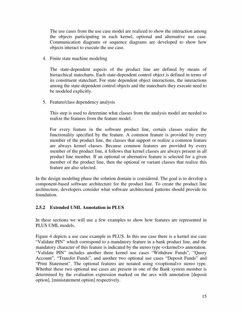
In PLUS the features are modeled by class diagrams. Figure 5 depicts a class diagram
representing a set of features with feature dependencies.
<<alternative feature>>Multi-line Display
<<alternative feature>>Analog Weight
<<optional feature>>Recipe
requires mutuallyincludes
Note: if two features are always needed together, these features are
considered a mutually inclusive features. This relation can also behandled by feature prerequisites relation.
Figure 5 an example of features with dependencies in PLUS
In this class diagram there is an optional feature Recipe, which has a “requires”
relationship with an “alternative feature – Multi-line Display” and a “mutually includes”
17
relationship with an “alternative feature – Analog Weight”. The relationships are
represented as associations in this diagram. A require relation means whenever optional
feature “Recipe” is present in the description of an instance of this product line, the
alternative feature “Multi-line Display” has to be present in this instance description as
well. “Mutually includes” is basically redundant as it can also be handled with a
“Requires” relation.
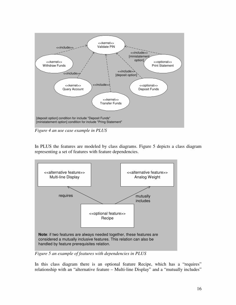
The relationship between features and use cases is a many to many relationship, and this
relationship is recorded in a table. Table 1 shows the relationships between features and
use cases in a microwave oven software product line example.
Table 1 Tabular representation of feature/use case relationships: microwave oven
software product line.
Feature
Name
Feature
Category
Use
Case
Name
Use Case
Category/Variation
Point (vp)
Variation
Point
Name
Microwave
Oven Kernel
common Cook Food Kernel
Light optional Cook Food vp Light
Turntable optional Cook Food vp Turntable
Beeper optional Cook Food vp Beeper
… … … … …
2.5.3 The Strength and Weakness of PLUS Method
The major strength of PLUS method is that feature modeling is successfully integrated
into the requirement and analysis modeling process of product line software development.
The product line software development process has been clearly defined, which includes
activities of feature modeling. The features represented in the feature model are related to
classical UML model, such as use case models, static models, dynamic models, etc.
The PLUS method has also a few weaknesses. The first weakness of PLUS is that
features are modeled by using class diagram instead of feature diagrams. The tree
structure of feature diagrams is an important characteristic of features, and the mandatory,
optional, and alternative features are also very well annotated in the feature diagram. The
feature diagrams make it much easier to understand the structures of the features, the
characteristics of the features, and the relationships between features. Another advantage
of feature diagrams is that it is very compact, a small feature diagram can contain quite
big mount of data.
The second weakness of PLUS is that the feature characteristics (mandatory, alternative,
optional) are also annotated in other UML diagrams, such as use case diagrams and class
diagrams. If a UML model itself is already complex, then extra feature annotation added
into the UML model makes it even more complex. With feature diagram those
information can be easily separated from the UML model.

18
The third weakness of PLUS is that this method only considers how features in a product
line can be modeled into UML models, as how to generate the UML models for a product
line member is not considered.
As so far we haven’t seen a method which both satisfies the requirements and eases the
process of product line development, so we propose a new method – FeatureUML – for
this purpose. The FeatureUML will use the strength of PLUS method, and try to remove
the weakness of the method. The FeatureUML method is described in details in Chapter 3.
19
3 FeatureUML Method
3.1 Problems FeatureUML Addresses
The FeatureUML method aims to define a systematic way of developing product
software product line. The current focus of this method is the domain analysis phase and
part of the application engineering phase. The modeling techniques used in this method
include feature diagrams and UML models. The method should satisfy the following
goals at the end:
� There should be a clear process defined for product line software system
development.
� The annotation for features should be defined in such way that the method should
keep the complexity of system analysis as simple as possible.
� The method should also provide a way to generate models for a member of the
product line.
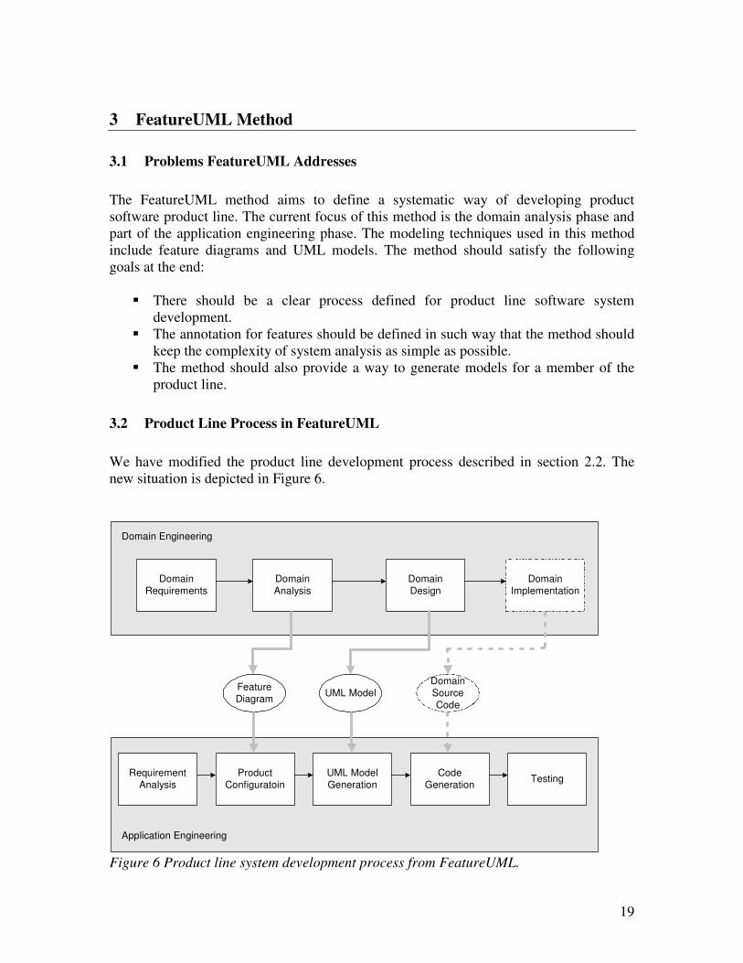
3.2 Product Line Process in FeatureUML
We have modified the product line development process described in section 2.2. The
new situation is depicted in Figure 6.
Domain
Analysis
Domain
Design
Domain Engineering
Application Engineering
Feature
DiagramUML Model
Domain
Implementation
Product
Configuratoin
Requirement
Analysis
UML Model
Generation
Code
GenerationTesting
Domain
Source
Code
Domain
Requirements
Figure 6 Product line system development process from FeatureUML.
20
3.2.1 Domain Engineering
Domain engineering is divided into the following phases:
1. Domain Requirements
The purpose of domain requirements is to define the scope of the domain, collect
the relevant domain information. The activities described in the PLUS method for
domain requirements are also used here. So the major activities involved in
domain requirements phase are:
� Product line scoping
� Use case modeling
� Feature modeling
At the end of the domain requirements we should gain a use case model, a feature
model and other relevant information about a domain.
2. Domain Analysis
The purpose of domain analysis is to identify the problem domain objects and the
information passed between them. We have modified the activities in the PLUS
method and the new set of the activities are as following:
� Static modeling
A problem-specific static model is defined. In this phase the mandatory,
optional, and alternative features are also mapped into the class elements –
namely class, attributes and options in the classes.
� Dynamic modeling
When the sequence diagrams are developed to show how objects interact to
execute the use case, the features in the feature model are also mapped into
the sequence diagrams.
� Finite state machine modeling
The state machine modeling is not considered in FeatureUML method at the
moment, it can be added into this method in the future.
� Feature model/UML model map validating
This step is to validate the UML model again the feature model. Validating
includes if all the features mapped in the UML model also exist in the feature
model, and the features in the feature model has been mapped into a set of
UML elements in the UML model.
3. Domain Design and Domain Implementation
The purpose of domain design is to develop an architecture for the family of
systems in the domain and to devise a production plan. The domain
implementation can be done in three approaches:
21
1. Approach one – the traditional approach
a. The domain code is written and the matrix to indicate the connection
between the code unit and the features is setup.
b. At the application engineering phase the UML model for a single member,
the feature model and the code/feature matrix is taken as input to generate
the code unit for this single member.
2. Approach two – component assembly
In this approach a set of components are implemented and the features are
mapped into the subset of the components. During the application engineering
phase the right subset of the components are selected according to the
configuration of the feature model, and these components are assembled into
the final system.
3. Approach three – the modern and future approach
As one of the current research trends on software development is Modern
Driven Architecture (MDA). In MDA the UML model is then divided into
two types: PIM (platform independent model) and PSM (platform specific
model). The PSM model is very close to the final source code, so it can be
used to generate source code. The UML models we develop here are PIM.
After the PIM is transformed into PSM the source code can be generated from
the PSM model. If this approach becomes reality, then the domain
development will be not required any more in the product line process.
Our current focus of the method is not on the domain development, so we will not
discuss this issue any further in this thesis.
3.2.2 Application Engineering
Application engineering is divided into the following phases:
1. Requirement analysis
During the requirements analysis for a new concrete application, we take
advantage of the existing domain model and describe customer needs using the
features from domain model. If new customer requirements are not found in the
domain model, then the domain engineering has to be refined and extended to
fulfill the new customer requirements.
2. Product configuration
22
The purpose of this phase is to use the custom requirements gathered in the
requirement analysis phase to configure the feature diagrams in the feature model.
The required optional features are selected, and decisions are made as which of
the feature options in the alternative feature should be chosen. At the end the
features present in the feature configuration should fulfill the requirements from a
single customer.
3. UML model generation
In the UML model generation phase the UML models created in the Domain
Engineering are used as input, and these UML models are processed
automatically against the feature configurations from the product configuration
phases. The output of this process is a UML model which is dedicated to a single
customer.
4. Code generation
In this phase the feature model, specific UML model and the domain source code
are used to generate the source code for a single customer. Currently this phase is
out of the scope of this project.
5. Test
The source code generated in code generation phase is compiled, tested and
packed in a desired format. The final package of the program is delivered to the
customer to go through the acceptance test.
23
4 Feature and UML Modeling in FeatureUML Tool
In this chapter we give a detailed introduction of the main activities in FeatureUML,
which are the feature modeling, the UML modeling, and the UML model processing in
our prototype tool.
4.1 Feature Modeling
During feature modeling we extract features out of the use case model and organize them
into feature diagrams.
4.1.1 Feature Types
The feature types, which can be illustrated in feature diagram, include mandatory,
optional and alternative types. An alternative type has to be combined with either a
mandatory or an optional type to derive two new types: mandatory alternative and
optional alternative. Thus in total we have the following four types of features in
FeatureUML:
� Mandatory feature
� Optional feature
� Mandatory alternative feature
� Optional alternative feature
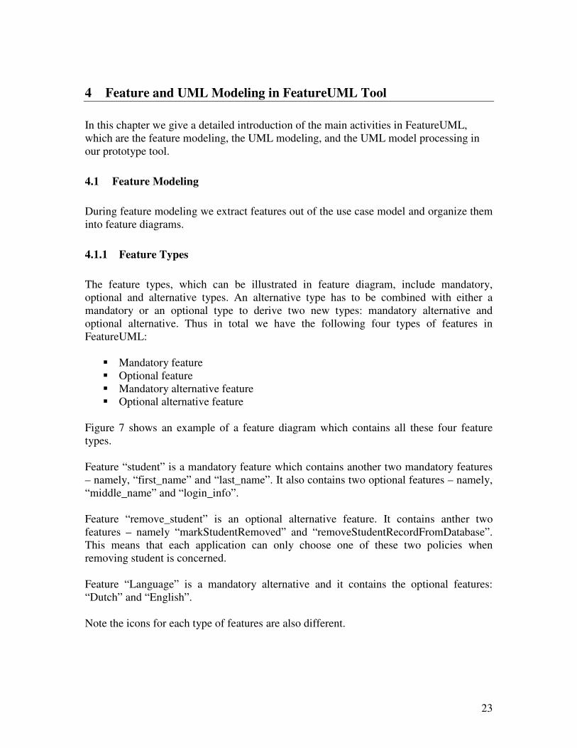
Figure 7 shows an example of a feature diagram which contains all these four feature
types.
Feature “student” is a mandatory feature which contains another two mandatory features
– namely, “first_name” and “last_name”. It also contains two optional features – namely,
“middle_name” and “login_info”.
Feature “remove_student” is an optional alternative feature. It contains anther two
features – namely “markStudentRemoved” and “removeStudentRecordFromDatabase”.
This means that each application can only choose one of these two policies when
removing student is concerned.
Feature “Language” is a mandatory alternative and it contains the optional features:
“Dutch” and “English”.
Note the icons for each type of features are also different.
24
Figure 7 four feature types in a feature diagram example.
4.1.2 Feature Cardinality
In FeatureUML we use a modified version of the feature cardinality described in section
2.3.1.2. The cardinalities of the mandatory and optional features are set to [1…*] and
[0…*] respectively. Our consideration for this change is that a mandatory feature or an
optional feature can be selected multiple times in a configuration of the feature models.
The second change was made to the feature cardinality is the alternative group feature
cardinality. In FeatureUML the feature options in an alternative feature are exclusive,
which means whenever we configure an alternative feature, we can only select one
feature option from this alternative feature.

25
The feature-cardinalities in FeatureUML are based on the concept described above and
are divided into two types:
Figure 8 feature cardinalities in an example of feature diagram
Figure 8 shows the same example from Figure 7 with cardinalities. The mandatory
feature “Bank Account” has a feature cardinality [1…4], which means that each student
should has at least one bank account, and can have up to maximal four account
information stored in the system.
Feature “Credit Account” has a cardinality of [0…4] which means each student can have
from 0 up to 4 credit account information stored in the system. This is also logic as a
student can only have up to 4 bank accounts.
Even though this concept is currently built into the tool, but it is not used in the UML
model mapping, and this can be extended in the future.
4.1.3 Feature Dependency
We have built both of the two types of the feature dependency into the tool. Figure 9
shows a feature diagram with one require dependency and one exclude dependency.
26
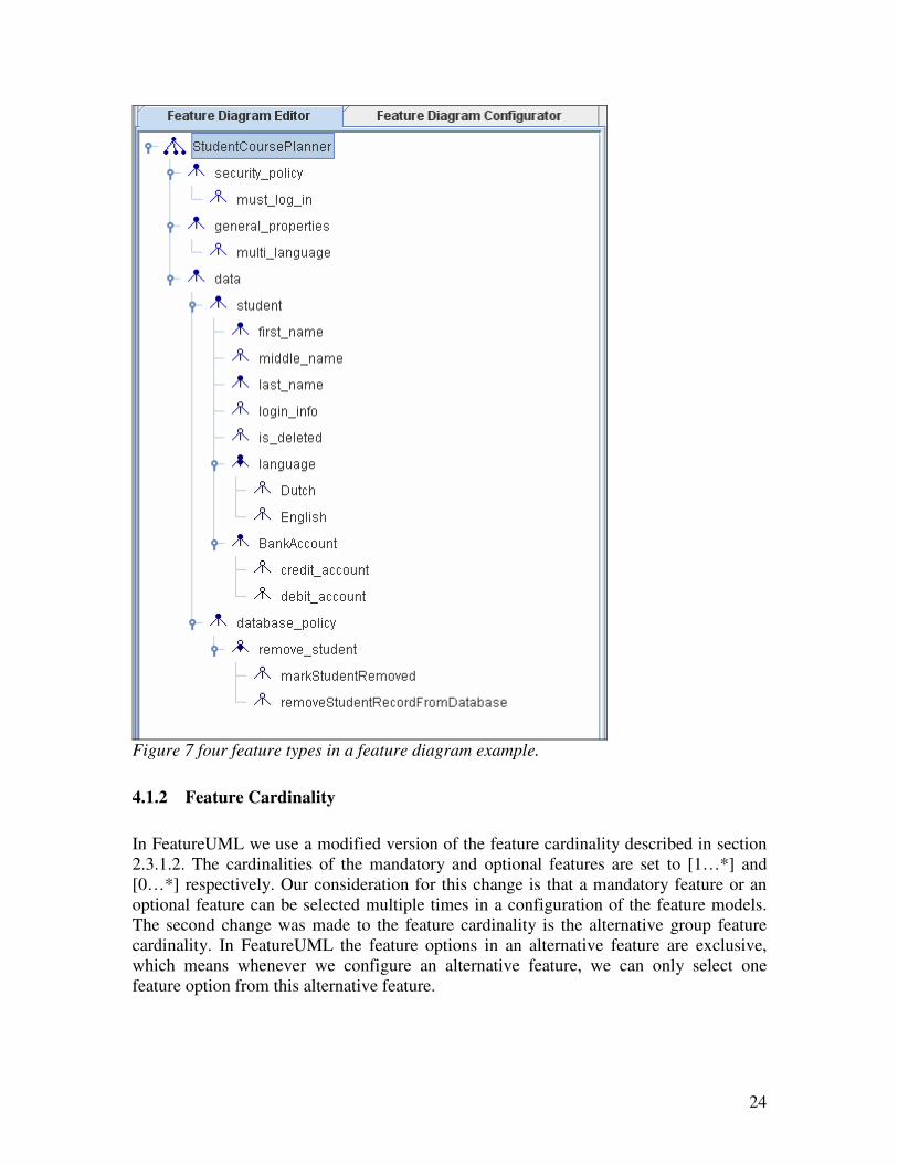
Feature “must_log_in” require “login_info” means whenever we select optional feature
“must_log_in” in a configuration, then feature “login_info” also has to be selected.
Feature “removeStudentRecordFromDatabase” has an exclude relationship with feature
“is_deleted”, which means if “removeStudentRecordFromDatabase” is selected, then we
can never select feature “is_deleted” in the same configuration. Vice versa is also valid.
Figure 9 feature dependencies between features in a feature diagram example.
27
4.2 UML Modeling
4.2.1 UML Diagram Feature Annotation
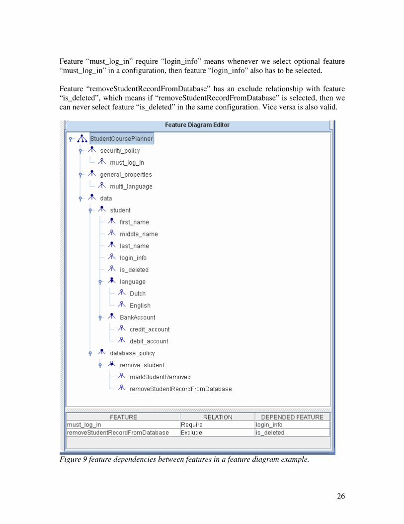
In the UML diagrams a single annotation is used to indicate that a feature is mapped into
a UML element, which is:
[FEATURE feature_name]
where “feature_name” is the name of the feature which is mapped into this UML element.
This annotation is used in both class diagrams and sequence diagrams. Figure 10 gives a
few examples of UML element/feature mappings.
Class
Attribute
Operation
Sequence
Diagram
Figure 10: a few examples of the UML element/feature mappings.
In the examples the following mappings are shown:
� The feature “login_info” is mapped into the class “Login”;
� The feature “multi_language” is mapped into the attribute “taughtInLanguage” in
the class “Course”;
� The feature “must_log_in” is mapped into the operation “login” in the class
“ApplicationServer”;
� The feature “must_log_in” is mapped into the sequence diagram “Log In”.
28
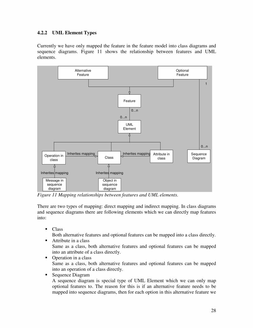
4.2.2 UML Element Types
Currently we have only mapped the feature in the feature model into class diagrams and
sequence diagrams. Figure 11 shows the relationship between features and UML
elements.
Feature
Class
UML
Element
Attribute in
classOperation in
class
Sequence
Diagram
Object in
sequence
diagram
Message insequence
diagram
0...n
0...n
Inherites mappingInherites mapping
Alternative
Feature
Optional
Feature
Inherites mapping Inherites mapping
1
0...n
Figure 11 Mapping relationships between features and UML elements.
There are two types of mapping: direct mapping and indirect mapping. In class diagrams
and sequence diagrams there are following elements which we can directly map features
into:
� Class
Both alternative features and optional features can be mapped into a class directly.
� Attribute in a class
Same as a class, both alternative features and optional features can be mapped
into an attribute of a class directly.
� Operation in a class
Same as a class, both alternative features and optional features can be mapped
into an operation of a class directly.
� Sequence Diagram
A sequence diagram is special type of UML Element which we can only map
optional features to. The reason for this is if an alternative feature needs to be
mapped into sequence diagrams, then for each option in this alternative feature we
29
need to make a sequence diagram. Instead of mapping an alternative feature to a
sequence diagram, we map each feature option in the alternative feature to a
sequence diagram.
In class diagrams we have mapped the features directly into the following two types of
UML elements:
� Attributes in class
When a feature is mapped into a class, then all the attributes in the class get this
mapping automatically.
� Operations in class
When a feature is mapped into a class, then all the operations in the class get this
mapping automatically.
In sequence diagrams the features are mapped into the following two types elements
indirectly:
� Objects in a sequence diagram
For a correct sequence diagram, each object in the sequence diagram should have
a base class. Consequently if a feature is mapped into a base class, then all the
object instances of this class get this mapping automatically.
� Messages in sequence diagram
For the same reason as objects in a sequence diagram, each message should be an
operation of the receiver object’s base class. If a feature is mapped into an
operation in a class, then all the corresponding messages of this operation get this
mapping automatically.
With the current implementation of the FeatureUML tool we only map optional and
alternative features into UML elements, as only these two features will need to be
configured during the product configuration phase, the mandatory features should always
be present in all the members of a product line.
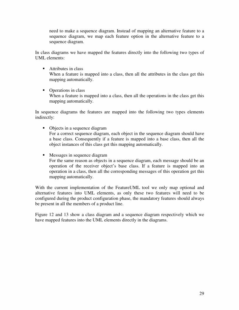
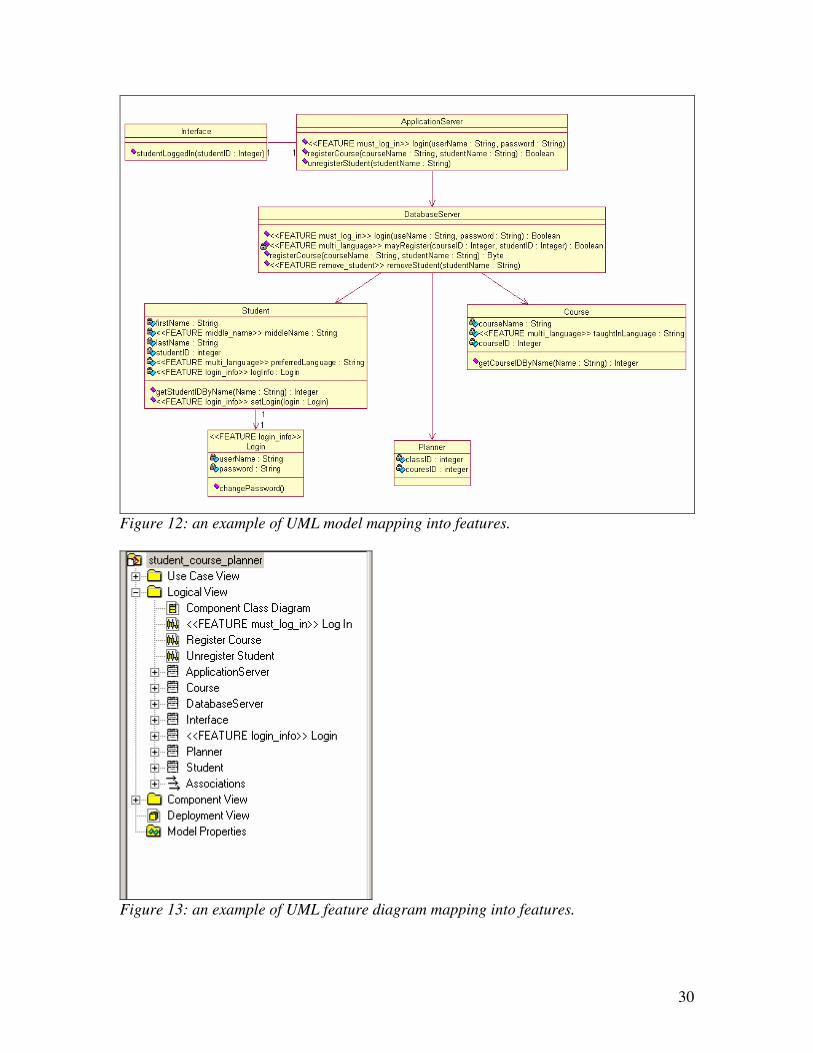
Figure 12 and 13 show a class diagram and a sequence diagram respectively which we
have mapped features into the UML elements directly in the diagrams.
30
Figure 12: an example of UML model mapping into features.
Figure 13: an example of UML feature diagram mapping into features.
31
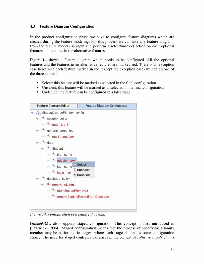
4.3 Feature Diagram Configuration
In the product configuration phase we have to configure feature diagrams which are
created during the feature modeling. For this process we can take any feature diagrams
from the feature models as input and perform a select/unselect action on each optional
features and features in the alternative features.
Figure 14 shows a feature diagram which needs to be configured. All the optional
features and the features in an alternative features are marked red. There is an exception
case here; with each feature marked in red (except the exception case) we can do one of
the three actions:
� Select: this feature will be marked as selected in the final configuration.
� Unselect: this feature will be marked as unselected in the final configuration.
� Undecide: the feature can be configured in a later stage.
Figure 14: configuration of a feature diagram.
FeatureUML also supports staged configuration. This concept is first introduced in
[Czarnecki, 2004]. Staged configuration means that the process of specifying a family
member may be performed in stages, where each stage eliminates some configuration
choice. The need for staged configuration arises in the context of software supply chains
32
[Greenfield and Short, 2004]. In general, supply chains require staged configuration of
platforms, components, and services. However, staged configuration may be required
even within one organization. For example, security policies could be configured in
stages for an entire enterprise, its divisions, and the individual computers. The enterprise
level configuration would determine the choices available to the divisions, and the
divisions would determine the choices available to the individual computers.
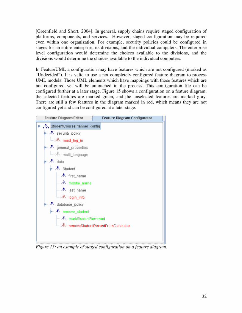
In FeatureUML a configuration may have features which are not configured (marked as
“Undecided”). It is valid to use a not completely configured feature diagram to process
UML models. Those UML elements which have mappings with those features which are
not configured yet will be untouched in the process. This configuration file can be
configured further at a later stage. Figure 15 shows a configuration on a feature diagram,
the selected features are marked green, and the unselected features are marked gray.
There are still a few features in the diagram marked in red, which means they are not
configured yet and can be configured at a later stage.
Figure 15: an example of staged configuration on a feature diagram.
33
4.4 UML Model Processing
4.4.1 Rules
UML model processing takes a configuration file and a UML model as input and checks
the UML elements in the UML model which have mappings with the features from the
configuration files. After the processing, the UML model should not contain any feature
mapping annotations any more for those features which have been configured in the
configuration file.
There are basically three types of operations which can be performed on a UML element
which a feature is mapped into:
� Feature marking elimination
If a UML element is marked to a feature which is selected in the configuration,
then the feature marking will be removed from this UML element. For example, if
a feature is mapped into a class as following:
[FEATURE login_info] Login
then after the processing the feature marking is gone, and the element looks like:
Login
� UML element elimination
If a UML element is marked to a feature which is unselected in the configuration,
then the UML element is simply removed from the UML model after the process.
For example a feature is mapped into an attribute in class “Student” as following:
[FEATURE login_info] login: Login;
After the processing this attribute is simply removed from the class “Student”.
� UML element substitution: if a mandatory or selected optional alternative feature
is mapped into a UML element, and there is an option from the alternative feature
which has been chosen, then this UML element’s name will be substituted with
the name of the selected option from the alternative feature. For example the
feature “removeStudent” is mapped into an operation in a class as following:
[FEATURE removeStudent] removeStudent();
The alternative feature “removeStudent” has two options:
“markStudentRemoved” and “removeStudentRecordFromDatabase”. If the option
“removeStudentRecordFromDatabase” is chosen from this alternative feature,
then after processing the operation will look like this:
34
removeStudentRecordFromDatabase();
So the feature marking is gone and the name of the operation is substituted with
the name of the selected option from the alternative feature.
4.4.2 Processes
The details of processing each type of UML elements are described below:
1. Feature marking elimination
When this action is applied on a UML element, except the feature marking is
removed from the UML element, no further action is performed.
2. UML element elimination
A. Sequence diagram: the sequence diagram is removed from the UML model,
and no further action is taken.
B. Attribute in a class: the attribute is removed from the class, and no further
action is taken.
C. Operation in a class: the operation is removed from the class, all the messages
corresponding to this operation are removed from sequence diagrams, and no
further action is taken.
D. Class
a) All the attributes in this class are removed; the process of removing each
attribute follows the process described in 2.B.
b) All the operations in this class are removed; the process of removing each
operation follows the process described in 2.C.
c) All the objects derived from this class are removed from all the sequence
diagrams
d) This class is removed.
3. UML element substitution
When this action is applied on a UML element, the name of the UML element is
substituted and the feature marking annotation is removed from the UML element.
No further action is performed.
35
5 FeatureUML Tool
For the FeatureUML method we have built a prototype to demonstrate the ideas. In this
section we will describe issues related to the tool.
5.1 General Goal
The general goal of this tool is to create an environment which supports the FeatureUML
method. The major activities defined in the FeatureUML method should be realized in
this tool, and these major activities include: feature modeling, feature configuration, and
UML model processing. UML model are made in Rational Rose (Release version:
2002.05.00).
5.2 Tool Requirements
The major functionalities in the FeatureUML tool are divided into four groups, and these
major functionalities are explained in the following sections.
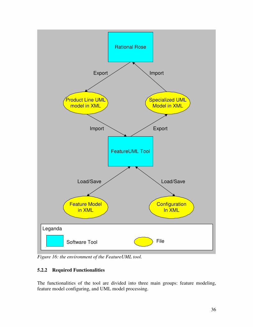
5.2.1 Environment Description
The environment of the tool is shown in Figure 16. Feature models are made in the
FeatureUML tool, and these feature models should be saved into the hard disk in XML
format. The FeatureUML tool should be able to load the existing feature models back
when they are needed.
The feature configuration is also done in the FeatureUML tool. The configured feature
models for a single member of the product line should be saved into the hard disc in
XML format. The FeatureUML tool should also be able to load the existing configured
feature models back when they are needed.
The UML models are made in Ration Rose, and they are exported from the Rational Rose
into XML files by using XMI (XML metadata Interchange format). The FeatureUML
should be able to load these UML models and process them against a special configured
feature model. After model processing the output of the UML model should be saved
back to disk in XML format again. This processed UML model should comply with the
original UML model format so it can be imported back to Rational Rose for viewing.
36
FeatureUML Tool
Rational Rose
Product Line UMLmodel in XML
Specialized UMLModel in XML
Export Import
ExportImport
Feature Model
in XML
Load/Save
Leganda
Software Tool File
Configuration
In XML
Load/Save
Figure 16: the environment of the FeatureUML tool.
5.2.2 Required Functionalities
The functionalities of the tool are divided into three main groups: feature modeling,
feature model configuring, and UML model processing.
37
1. Feature Modeling
The users should be able to create feature models. Each feature model contains
multiple feature diagrams. Each feature diagram consists of mandatory features,
optional features, mandatory alternative features, and optional alternative features.
Thus the users should be able to create new feature diagrams in a feature model,
and the users should also be able to create all these four types of features in each
feature diagram.
Each feature model should be saved into hard disk in XML format, and the tool
should be able to load the existing feature models. The users should be able to
modify the feature diagrams in the feature model, and the features in each feature
diagram. The users should also be able to remove feature diagrams from a feature
model and features from a feature diagram.
2. Feature Model Configuring
The tool has to allow uses to configure an existing feature models for a product
line. So after a feature model is loaded into the tool, the user can decide which
optional features should be selected or deselected; which feature options in the
alternative features should be selected. The users don’t have to configure the
mandatory features, as they are always present for all the members of the product
line.
The configuration can be preformed in stages, which means that users don’t have
to configure all the optional and alternative features at one go. The users should
be able to save the configured feature model onto hard disk in XML format at any
stage as they wish. These configurations can be loaded back into the program
again at a later stage for further configuration.
3. UML Model Processing
The tool should be able to load an UML model in XML format for a product line
which is made in Rational Rose. The users should be able to process this UML
model against a special configuration of a feature model. This configuration
doesn’t have to be completed, which means it is possible to have not configured
optional and alternative features in the configuration. Those UML elements which
have mappings with those not configured features should not be processed during
the UML model processing. The output UML model after the processing should
be saved back into the hard disk in XML format again, and the file should comply
with the original UML model file format so it can be imported back to Rational
Rose for viewing.
5.3 Tool Design
In this section we give an introduction to the design issues of the FeatureUML tool.
38
5.3.1 Data Structure Analysis
The FeatureUML tool has to handle three different kinds of data, feature diagrams,
configuration of the feature diagram, and UML models, and all these three kinds of data
exist for the purpose of a product line. So we organize data in the program in a project.
Project is the container for a product line software system, and a project contains the
following elements:
� Feature model of a product line: each feature model contains multiple feature
diagrams;
� UML model of a product line: each product line can contain multiple UML
models;
� Specialization for a member of the product line.
Each specialization contains the following two types of data again:
� Configuration of the feature model for a member of the product line
� Processed UML model for a member of the product line
5.3.2 Use Cases
Based on the required functionalities and the data structure analysis from the tool, we
have divided the use cases of the tool into the following four categories.
1. Project
a. New project – to create a new project.
b. Load project – to load an existing project.
c. Save project – to save a project and all the contents in this project into files.
2. Feature Diagram
a. New feature diagram – to create a new feature diagram
b. Remove feature diagram – to remove an existing feature diagram
c. New Mandatory Feature – to create a mandatory feature in a feature diagram
d. New Optional Feature – to create an optional feature in a feature diagram
e. New Mandatory Alternative Feature – to create a mandatory alternative
feature in a feature diagram
f. New Optional Alternative Feature – to create an optional alternative feature
in a feature diagram
g. Remove feature – to remove an existing feature from a feature diagram
h. Define dependency – to define dependencies between the features in a feature
diagram
3. Specialization
39
a. New specialization – to create a new specialization; each specialization
represents a single member of the product line.
b. Delete specialization – to delete an existing specialization.
c. New configuration – to create a new configuration for a specialization. For
each specialization multiple configurations can be created. Each configuration
takes a feature diagram from the project as input, and users can perform
configuration actions on the features from this feature diagram.
d. Update configuration – it is possible to update a configuration if the input
feature diagram is changed for convenience. After updating, the configuration
contains the same features again as in the input feature diagram.
e. Delete configuration – to delete a configuration from a specialization.
4. UML models
a. Load UML model – to load an existing UML model. The UML models are
made in Rational Rose (version: 7.6.0109.2314; release version: 2002.05.00)
and the file format of the UML models is XML file. For each project multiple
UML models can be loaded.
b. Delete UML model – to delete a loaded UML model from the project.
c. Process UML model – this function can only be performed in a specialization
after at least one feature diagram has been configured for this specialization.
The process takes a configuration from the specialization and a UML model
from the project as input, and process the UML model against the
configuration. After processing the output UML model is part of the
specialization where the configuration is taken from.
d. Reprocessing UML model –FeatureUML supports staged configuration. If a
configuration is further configured, we can process the UML models which
have been processed against this configuration again.
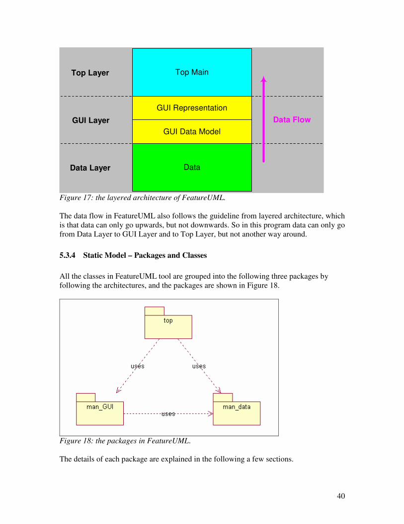
5.3.3 Architecture
FeatureUML uses a layered architecture which is shown in Figure 17. There are three
layers in the architecture:
1. Data Layer
This is the bottom layer of the architecture and it holds all the data in the program,
such as features, feature diagrams, configuration, UML models, etc.
2. GUI Layer
GUI layer contains two sub-layers. The bottom sub-layer holds all GUI data
models which hold the data part for all the GUI components. The top sub-layer is
the GUI representation which contains all the visual components from the
program.
3. Top Layer
The top layer is the container which holds all the GUI layer components together,
and organizes all the GUI components to react on the user commands.
40
Data
GUI Representation
GUI Data Model
Top MainTop Layer
GUI Layer
Data Layer
Data Flow
Figure 17: the layered architecture of FeatureUML.
The data flow in FeatureUML also follows the guideline from layered architecture, which
is that data can only go upwards, but not downwards. So in this program data can only go
from Data Layer to GUI Layer and to Top Layer, but not another way around.
5.3.4 Static Model – Packages and Classes
All the classes in FeatureUML tool are grouped into the following three packages by
following the architectures, and the packages are shown in Figure 18.
Figure 18: the packages in FeatureUML.
The details of each package are explained in the following a few sections.
41
5.3.4.1 Package man_data
This package contains classes for three different purposes:
1. Feature – there are a set of classes which hold information related to a feature;
2. UML Element - there are a set of classes which hold information related to a
UML element from a UML model;
3. Container – there are a set of classes which act as data container, which means
that an object instance from this type of class can multiple object instances from
other type of classes.
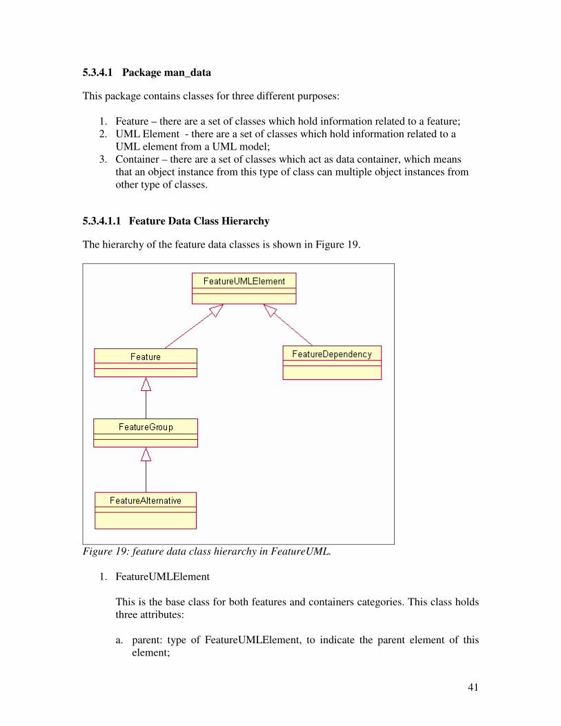
5.3.4.1.1 Feature Data Class Hierarchy
The hierarchy of the feature data classes is shown in Figure 19.
Figure 19: feature data class hierarchy in FeatureUML.
1. FeatureUMLElement
This is the base class for both features and containers categories. This class holds
three attributes:
a. parent: type of FeatureUMLElement, to indicate the parent element of this
element;
42
b. elementName: type of String, to indicate the name of this element;
c. changed: type of Boolean, to indication if this element’s attributes have been
changed.
This class contains operations related to retrieving and changing the values of
each attribute, and the basic structure of saving functionalities is also built in this
class.
2. Feature
This class extends FeatureUMLElement and it is the base class for all types of
features. This class contains four attributes:
a. minCardinality – to indicate the minimum cardinality of this feature;
b. maxCardinality – to indicate the maximum cardinality of this feature;
c. configState – to indicate the configuration state of this feature. The
configuration state can be one of the following three: selected, deselected, or
undecided;
d. previousConfigState – to hold the previous config state. This field is used
during the configuration process. When a use tries to select or unselect a
feature from the feature diagram, the previous configuration state is held in
this field. If the select or deselect action is not successful, then the
configuration state of this element is set back to the previous configuration
state.
This class contains operations related to retrieving and changing the values of
each attribute, and it also contains special procedures for saving this feature into a
XML file.
3. FeatureGroup
This class extends Feature and contains a child feature list. Each feature from
feature diagram in FeatureUML is represented by an object of the class
FeatureGroup. If a feature contains other features, then those features are held in
the child feature list of this object as references. If a feature is a leaf feature, then
the child feature list of this object is simply empty.
This class also holds the functionalities of manipulating a feature or the features
in the child feature list.
4. FeatureAlternative
This class extends FeatureGroup and it is to represent an alternative feature. An
alternative feature is a special type of feature-group as only one of the child
features from this group can be selected for each member of the product line.
43
5. FeatureDependency
This class is to describe the “exclude” or “required” relationship between two
features.
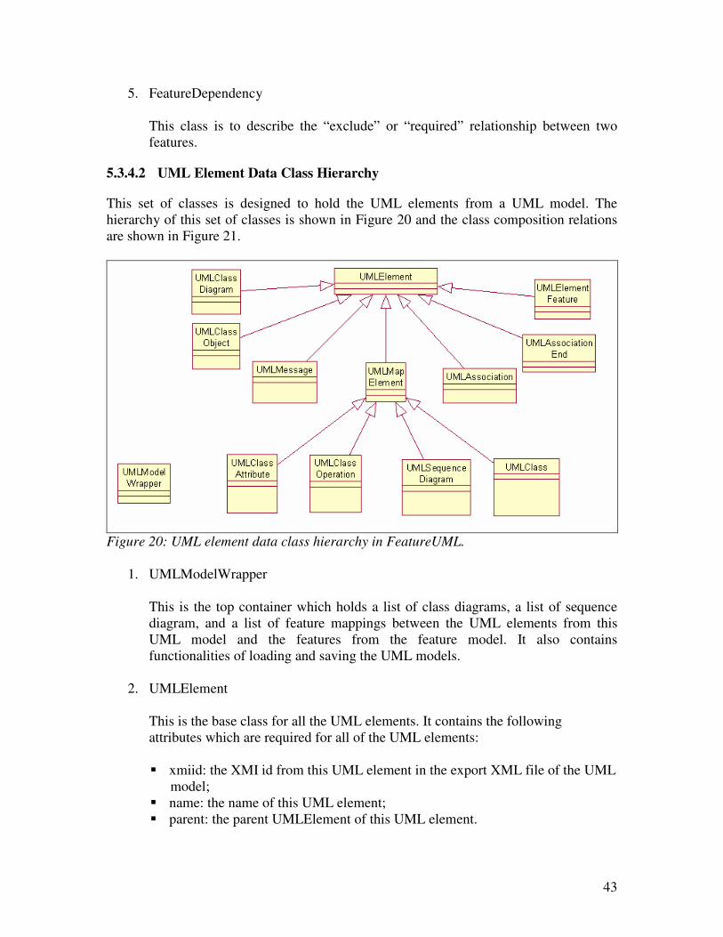
5.3.4.2 UML Element Data Class Hierarchy
This set of classes is designed to hold the UML elements from a UML model. The
hierarchy of this set of classes is shown in Figure 20 and the class composition relations
are shown in Figure 21.
Figure 20: UML element data class hierarchy in FeatureUML.
1. UMLModelWrapper
This is the top container which holds a list of class diagrams, a list of sequence
diagram, and a list of feature mappings between the UML elements from this
UML model and the features from the feature model. It also contains
functionalities of loading and saving the UML models.
2. UMLElement
This is the base class for all the UML elements. It contains the following
attributes which are required for all of the UML elements:
� xmiid: the XMI id from this UML element in the export XML file of the UML
model;
� name: the name of this UML element;
� parent: the parent UMLElement of this UML element.
44
This class also contains operations related to retrieving the values of the attributes.
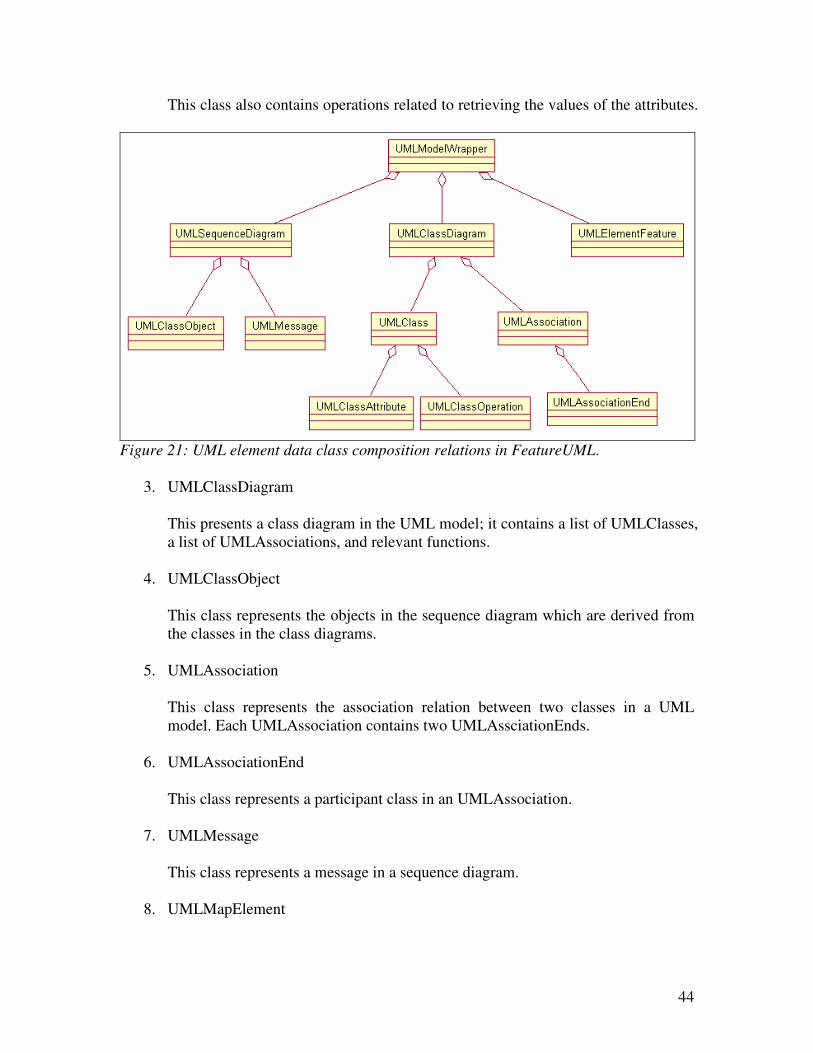
Figure 21: UML element data class composition relations in FeatureUML.
3. UMLClassDiagram
This presents a class diagram in the UML model; it contains a list of UMLClasses,
a list of UMLAssociations, and relevant functions.
4. UMLClassObject
This class represents the objects in the sequence diagram which are derived from
the classes in the class diagrams.
5. UMLAssociation
This class represents the association relation between two classes in a UML
model. Each UMLAssociation contains two UMLAssciationEnds.
6. UMLAssociationEnd
This class represents a participant class in an UMLAssociation.
7. UMLMessage
This class represents a message in a sequence diagram.
8. UMLMapElement
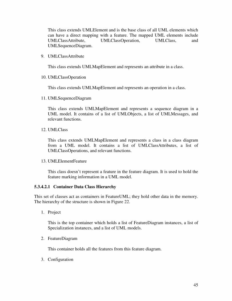
45
This class extends UMLElement and is the base class of all UML elements which
can have a direct mapping with a feature. The mapped UML elements include
UMLClassAttribute, UMLClassOperation, UMLClass, and
UMLSequenceDiagram.
9. UMLClassAttribute
This class extends UMLMapElement and represents an attribute in a class.
10. UMLClassOperation
This class extends UMLMapElement and represents an operation in a class.
11. UMLSequenceDiagram
This class extends UMLMapElement and represents a sequence diagram in a
UML model. It contains of a list of UMLObjects, a list of UMLMessages, and
relevant functions.
12. UMLClass
This class extends UMLMapElement and represents a class in a class diagram
from a UML model. It contains a list of UMLClassAttributes, a list of
UMLClassOperations, and relevant functions.
13. UMLElementFeature
This class doesn’t represent a feature in the feature diagram. It is used to hold the
feature marking information in a UML model.
5.3.4.2.1 Container Data Class Hierarchy
This set of classes act as containers in FeatureUML; they hold other data in the memory.
The hierarchy of the structure is shown in Figure 22.
1. Project
This is the top container which holds a list of FeatureDiagram instances, a list of
Specialization instances, and a list of UML models.
2. FeatureDiagram
This container holds all the features from this feature diagram.
3. Configuration
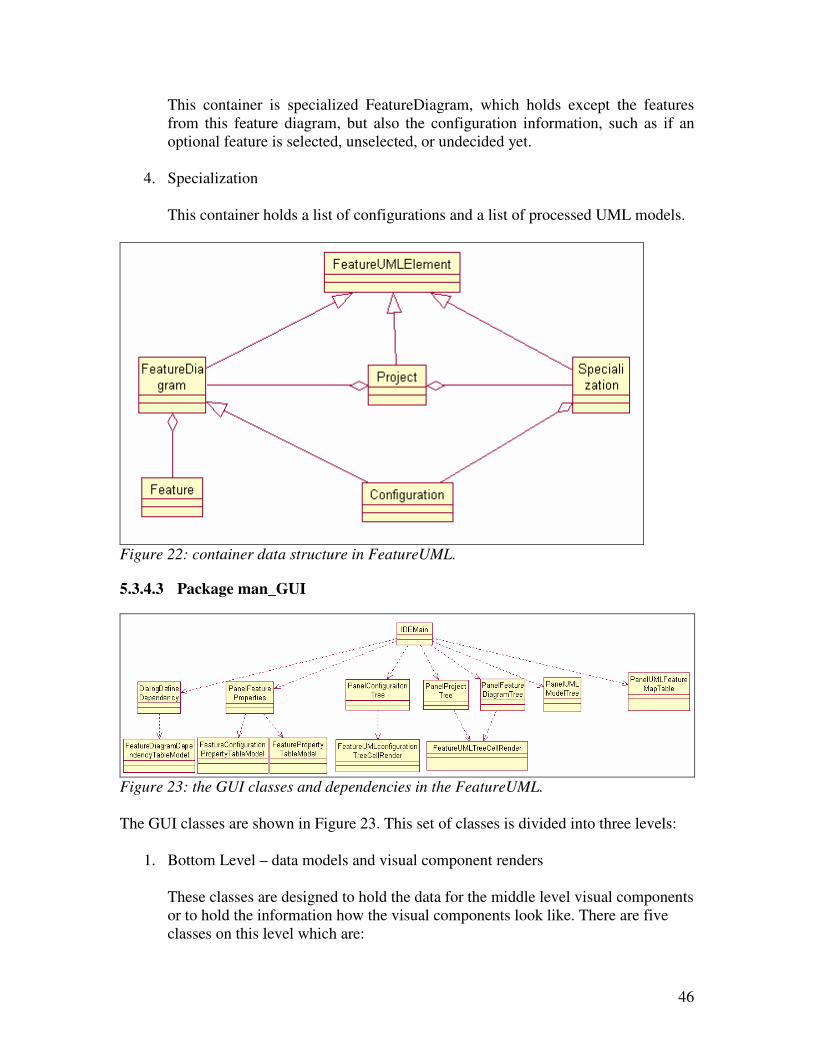
46
This container is specialized FeatureDiagram, which holds except the features
from this feature diagram, but also the configuration information, such as if an
optional feature is selected, unselected, or undecided yet.
4. Specialization
This container holds a list of configurations and a list of processed UML models.
Figure 22: container data structure in FeatureUML.
5.3.4.3 Package man_GUI
Figure 23: the GUI classes and dependencies in the FeatureUML.
The GUI classes are shown in Figure 23. This set of classes is divided into three levels:
1. Bottom Level – data models and visual component renders
These classes are designed to hold the data for the middle level visual components
or to hold the information how the visual components look like. There are five
classes on this level which are:
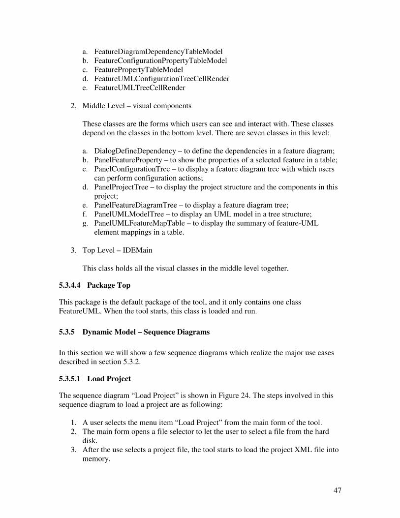
47
a. FeatureDiagramDependencyTableModel
b. FeatureConfigurationPropertyTableModel
c. FeaturePropertyTableModel
d. FeatureUMLConfigurationTreeCellRender
e. FeatureUMLTreeCellRender
2. Middle Level – visual components
These classes are the forms which users can see and interact with. These classes
depend on the classes in the bottom level. There are seven classes in this level:
a. DialogDefineDependency – to define the dependencies in a feature diagram;
b. PanelFeatureProperty – to show the properties of a selected feature in a table;
c. PanelConfigurationTree – to display a feature diagram tree with which users
can perform configuration actions;
d. PanelProjectTree – to display the project structure and the components in this
project;
e. PanelFeatureDiagramTree – to display a feature diagram tree;
f. PanelUMLModelTree – to display an UML model in a tree structure;
g. PanelUMLFeatureMapTable – to display the summary of feature-UML
element mappings in a table.
3. Top Level – IDEMain
This class holds all the visual classes in the middle level together.
5.3.4.4 Package Top
This package is the default package of the tool, and it only contains one class
FeatureUML. When the tool starts, this class is loaded and run.
5.3.5 Dynamic Model – Sequence Diagrams
In this section we will show a few sequence diagrams which realize the major use cases
described in section 5.3.2.
5.3.5.1 Load Project
The sequence diagram “Load Project” is shown in Figure 24. The steps involved in this
sequence diagram to load a project are as following:
1. A user selects the menu item “Load Project” from the main form of the tool.
2. The main form opens a file selector to let the user to select a file from the hard
disk.
3. After the use selects a project file, the tool starts to load the project XML file into
memory.
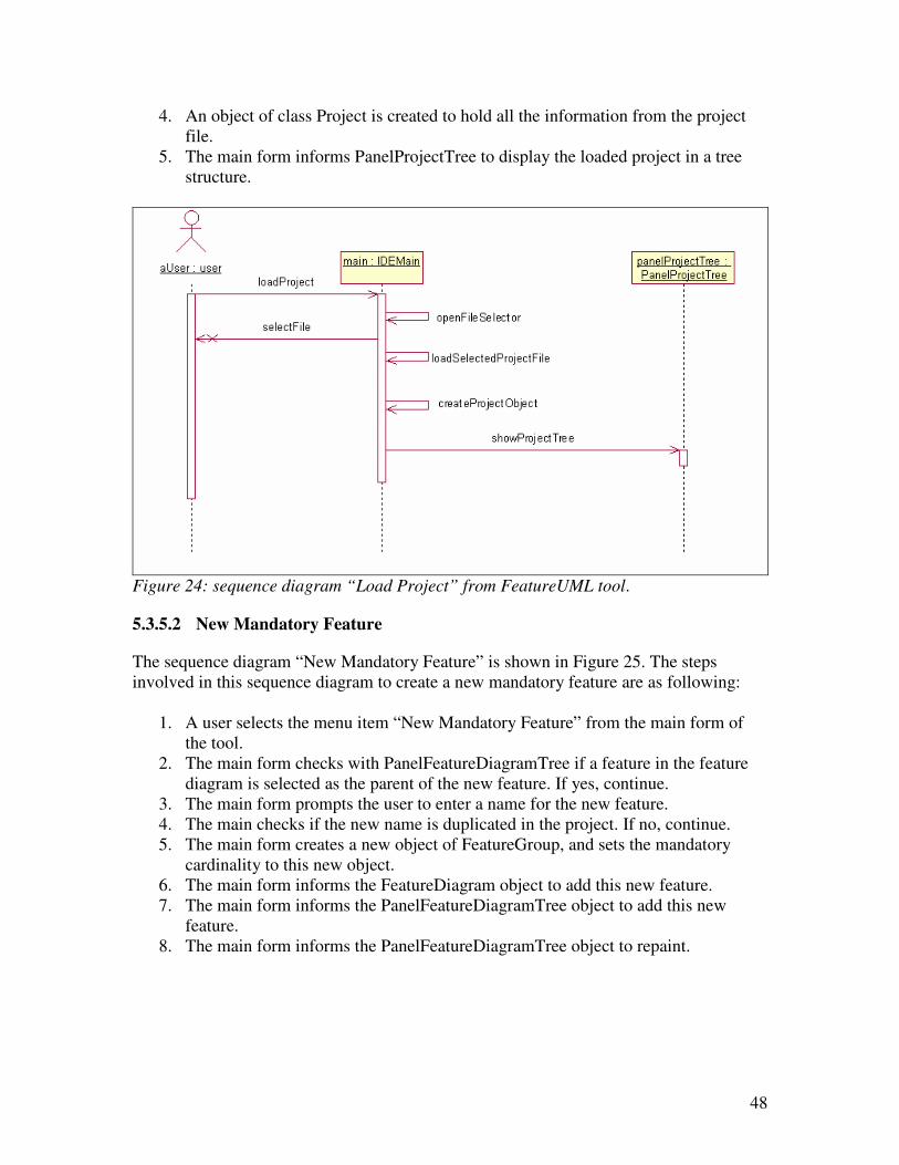
48
4. An object of class Project is created to hold all the information from the project
file.
5. The main form informs PanelProjectTree to display the loaded project in a tree
structure.
Figure 24: sequence diagram “Load Project” from FeatureUML tool.
5.3.5.2 New Mandatory Feature
The sequence diagram “New Mandatory Feature” is shown in Figure 25. The steps
involved in this sequence diagram to create a new mandatory feature are as following:
1. A user selects the menu item “New Mandatory Feature” from the main form of
the tool.
2. The main form checks with PanelFeatureDiagramTree if a feature in the feature
diagram is selected as the parent of the new feature. If yes, continue.
3. The main form prompts the user to enter a name for the new feature.
4. The main checks if the new name is duplicated in the project. If no, continue.
5. The main form creates a new object of FeatureGroup, and sets the mandatory
cardinality to this new object.
6. The main form informs the FeatureDiagram object to add this new feature.
7. The main form informs the PanelFeatureDiagramTree object to add this new
feature.
8. The main form informs the PanelFeatureDiagramTree object to repaint.
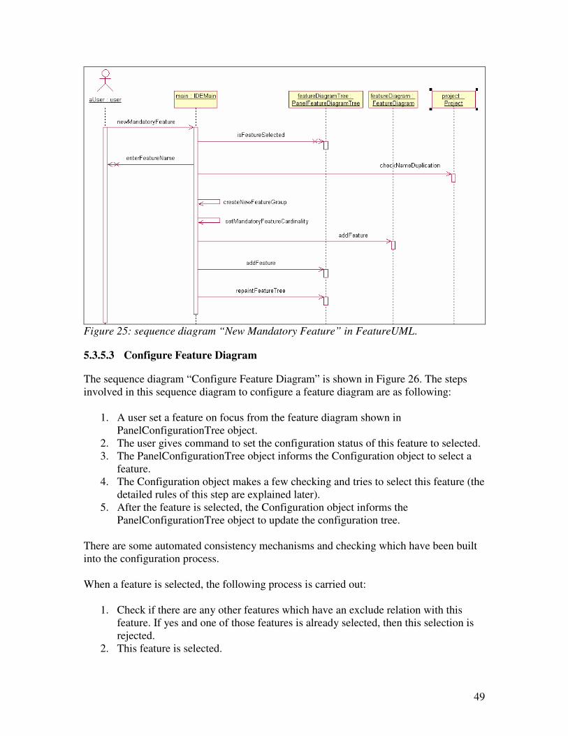
49
Figure 25: sequence diagram “New Mandatory Feature” in FeatureUML.
5.3.5.3 Configure Feature Diagram
The sequence diagram “Configure Feature Diagram” is shown in Figure 26. The steps
involved in this sequence diagram to configure a feature diagram are as following:
1. A user set a feature on focus from the feature diagram shown in
PanelConfigurationTree object.
2. The user gives command to set the configuration status of this feature to selected.
3. The PanelConfigurationTree object informs the Configuration object to select a
feature.
4. The Configuration object makes a few checking and tries to select this feature (the
detailed rules of this step are explained later).
5. After the feature is selected, the Configuration object informs the
PanelConfigurationTree object to update the configuration tree.
There are some automated consistency mechanisms and checking which have been built
into the configuration process.
When a feature is selected, the following process is carried out:
1. Check if there are any other features which have an exclude relation with this
feature. If yes and one of those features is already selected, then this selection is
rejected.
2. This feature is selected.
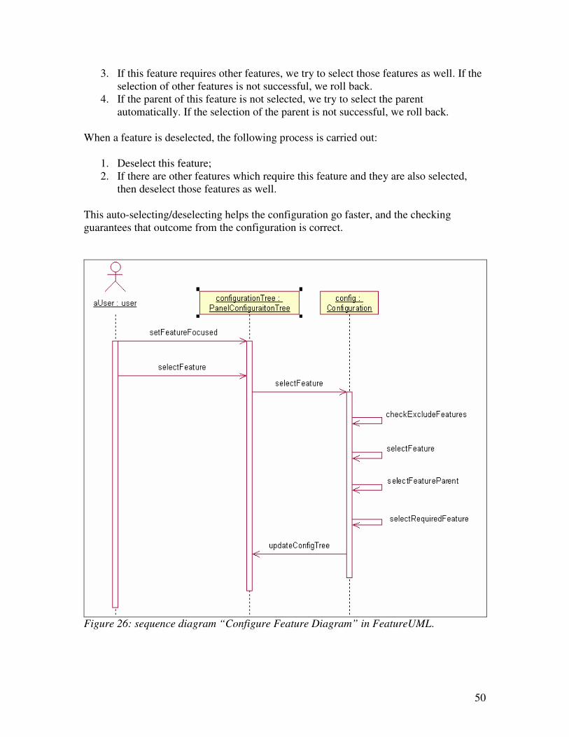
50
3. If this feature requires other features, we try to select those features as well. If the
selection of other features is not successful, we roll back.
4. If the parent of this feature is not selected, we try to select the parent
automatically. If the selection of the parent is not successful, we roll back.
When a feature is deselected, the following process is carried out:
1. Deselect this feature;
2. If there are other features which require this feature and they are also selected,
then deselect those features as well.
This auto-selecting/deselecting helps the configuration go faster, and the checking
guarantees that outcome from the configuration is correct.
Figure 26: sequence diagram “Configure Feature Diagram” in FeatureUML.
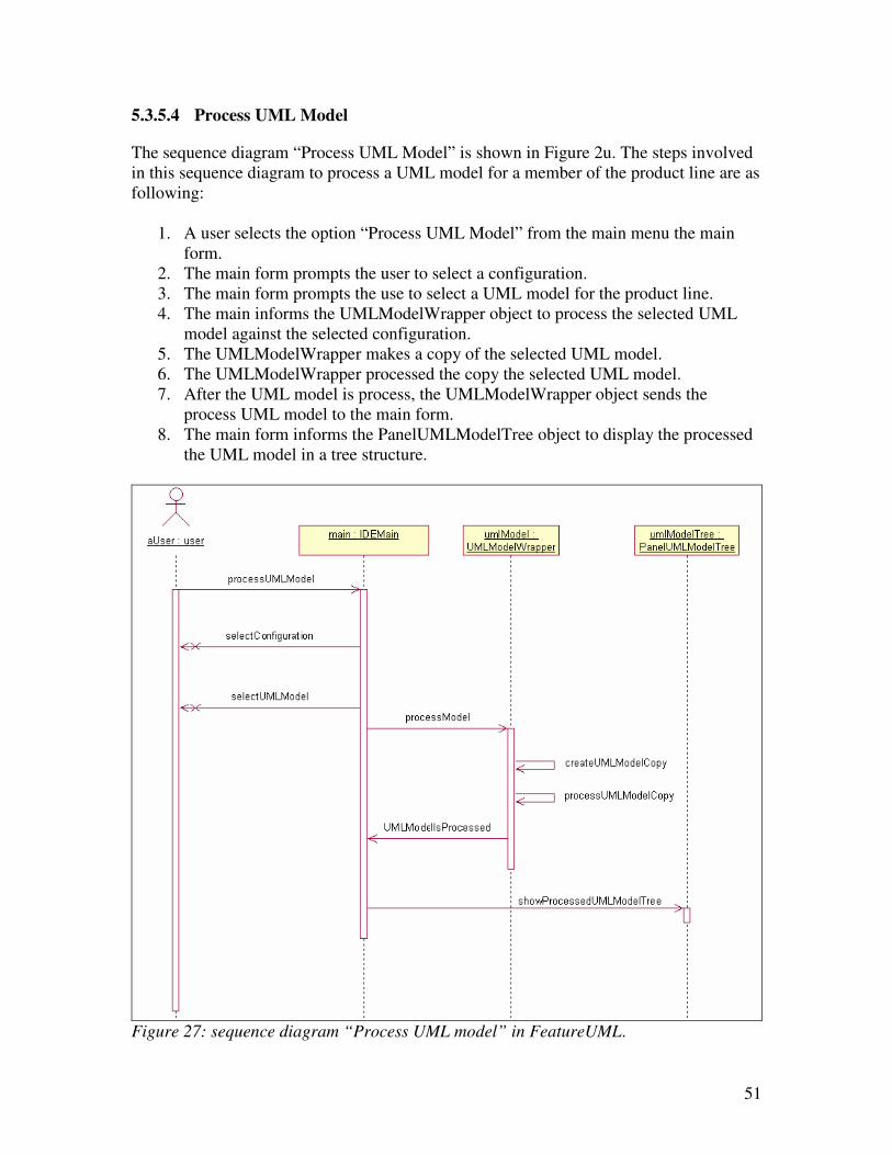
51
5.3.5.4 Process UML Model
The sequence diagram “Process UML Model” is shown in Figure 2u. The steps involved
in this sequence diagram to process a UML model for a member of the product line are as
following:
1. A user selects the option “Process UML Model” from the main menu the main
form.
2. The main form prompts the user to select a configuration.
3. The main form prompts the use to select a UML model for the product line.
4. The main informs the UMLModelWrapper object to process the selected UML
model against the selected configuration.
5. The UMLModelWrapper makes a copy of the selected UML model.
6. The UMLModelWrapper processed the copy the selected UML model.
7. After the UML model is process, the UMLModelWrapper object sends the
process UML model to the main form.
8. The main form informs the PanelUMLModelTree object to display the processed
the UML model in a tree structure.
Figure 27: sequence diagram “Process UML model” in FeatureUML.
52
5.4 Tool Implementation
5.4.1 Source Code
The program is written in Java and can be run on the J2SE platform (Java 2 Standard
Edition 6). Apart from the core API functions from the J2SE platform we have used the
following external packages to implement this tool:
� xml-apis.jar
� xercesImpl.jar
� xercesSamples.jar
� javax.xml package from the J2EE (Java 2 Enterprise Edition 5) platform.
These packages are mainly used for loading UML models and saving the internal data
structure into a file in XML format.
5.4.2 File Structure
The file structures from FeatureUML are exactly the same as shown in the main interface.
Figure 28 shows an example of the file structure. The root directory is the project name,
under project root there are three directories:
� Feature Diagrams
� Specializations
� UML models
The contents of each directory are the same as internal project structure. Only differences
are:
� Project file – under project root a project file is made, and this file stores the
locations of other content files of this project.
� Specialization file – under each specialization directory a specialization file is
made, and this file stores the locations of all the configurations files and processed
UML models from this specialization.
All the files saved in FeatureUML are in XML format. There are following file
extensions which are created in FeatureUML:
� FeatureUML Project XML file (.fpx): project file extension
� FeatureUML Feature Diagram XML file (.fdx): feature diagram file extension
� FeatureUML Specialization XML file(.fsx): specialization file extension
� FeatureUML Configuration XML file (.fcx): configuration file extension
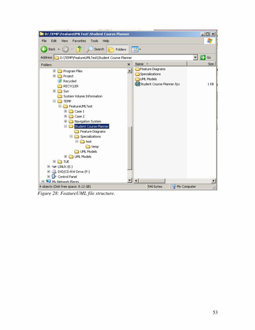
53
Figure 28: FeatureUML file structure.
54
6 Case Study – Navigation System
In this chapter we are going to show a case study of navigation system. We won’t show
the whole feature models and UML models of the navigation system, but only a portion
of the system to demonstrate our ideas.
6.1 Variation Points of Navigation System
1. Map Media
First we will show two variation points in a navigation system. Navigation
systems can be used in different kind of hardware, such as mobile telephones,
PDAs, or CD players. For each different type of hardware where a navigation
system is run, it is very likely that we will use different map media to store the
map information. For example, for CD players we will use CDs to store the map;
for PDAs we will use flash cards to store the map. This is the first variation point
in our navigation system and we call this variation point as “Map Media”.
2. Voice Guide
Very often a navigation system has a voice guide function, but this is not always
necessary. For some cheap versions we can only show the route on a map without
a voice guide. So with or without voice guide represents the second variation
point in our navigation system and we call this variation point as “Voice Guide”.
3. Route Selection
These days a navigation system is not only used by car drivers, but also by the
people who cycle or simply walk. The route that the navigation system calculates
is definitely different for a car user or a bicycle user. Even for car user along there
might also be different route types, such as with highway or without, with toll
way or without, etc. All these different types of route for a different purpose
present the third variation point in out navigation system and we call this variation
point as “Route Selection”.
4. Map Zoom
When a map is viewed, the users might want to zoom in the map to see the details
or they might want to zoom out to get an overall picture of the whole area. This
zoom in and out function becomes our fourth variation point and we call this
variation point “Map Zoom”.
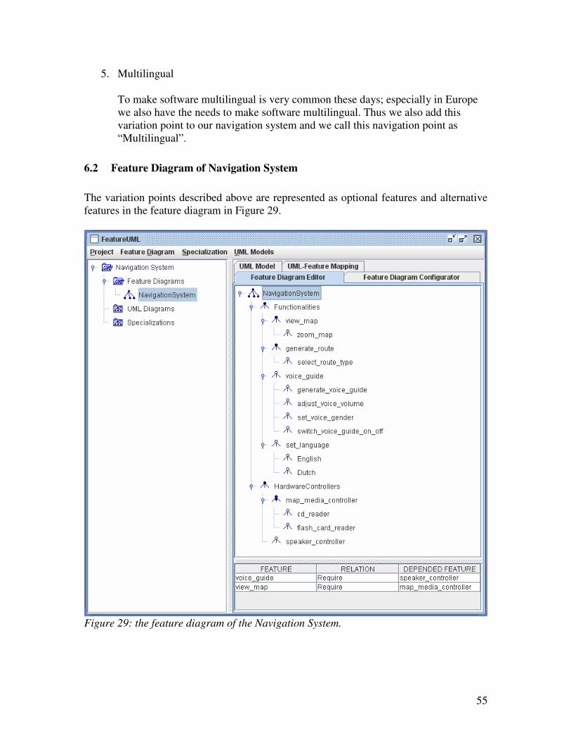
55
5. Multilingual
To make software multilingual is very common these days; especially in Europe
we also have the needs to make software multilingual. Thus we also add this
variation point to our navigation system and we call this navigation point as
“Multilingual”.
6.2 Feature Diagram of Navigation System
The variation points described above are represented as optional features and alternative
features in the feature diagram in Figure 29.
Figure 29: the feature diagram of the Navigation System.
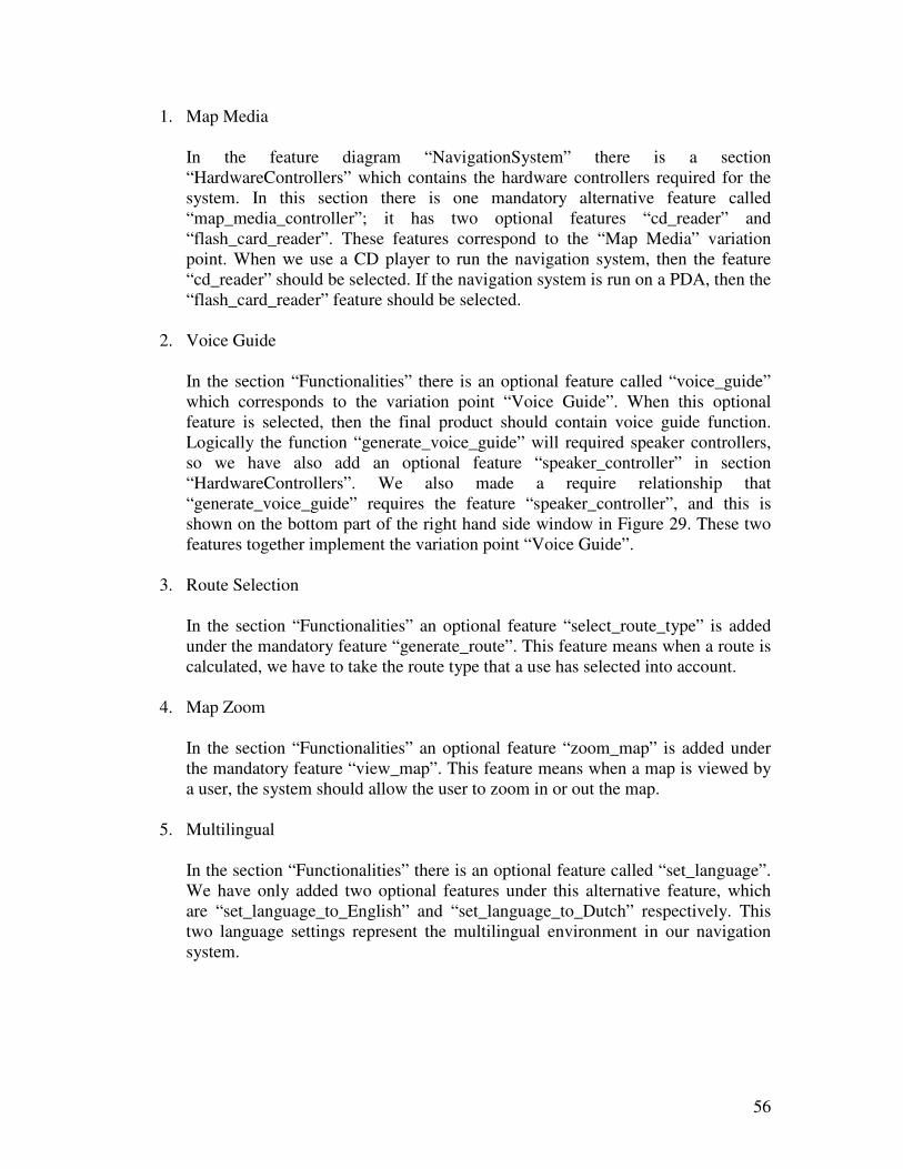
56
1. Map Media
In the feature diagram “NavigationSystem” there is a section
“HardwareControllers” which contains the hardware controllers required for the
system. In this section there is one mandatory alternative feature called
“map_media_controller”; it has two optional features “cd_reader” and
“flash_card_reader”. These features correspond to the “Map Media” variation
point. When we use a CD player to run the navigation system, then the feature
“cd_reader” should be selected. If the navigation system is run on a PDA, then the
“flash_card_reader” feature should be selected.
2. Voice Guide
In the section “Functionalities” there is an optional feature called “voice_guide”
which corresponds to the variation point “Voice Guide”. When this optional
feature is selected, then the final product should contain voice guide function.
Logically the function “generate_voice_guide” will required speaker controllers,
so we have also add an optional feature “speaker_controller” in section
“HardwareControllers”. We also made a require relationship that
“generate_voice_guide” requires the feature “speaker_controller”, and this is
shown on the bottom part of the right hand side window in Figure 29. These two
features together implement the variation point “Voice Guide”.
3. Route Selection
In the section “Functionalities” an optional feature “select_route_type” is added
under the mandatory feature “generate_route”. This feature means when a route is
calculated, we have to take the route type that a use has selected into account.
4. Map Zoom
In the section “Functionalities” an optional feature “zoom_map” is added under
the mandatory feature “view_map”. This feature means when a map is viewed by
a user, the system should allow the user to zoom in or out the map.
5. Multilingual
In the section “Functionalities” there is an optional feature called “set_language”.
We have only added two optional features under this alternative feature, which
are “set_language_to_English” and “set_language_to_Dutch” respectively. This
two language settings represent the multilingual environment in our navigation
system.
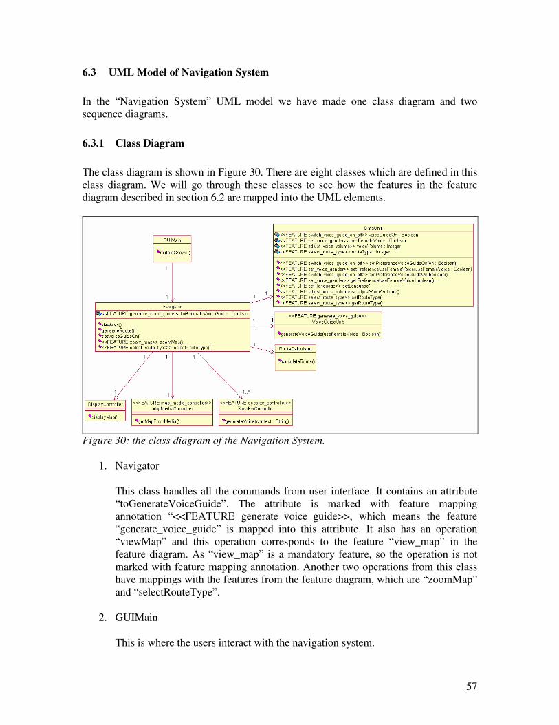
57
6.3 UML Model of Navigation System
In the “Navigation System” UML model we have made one class diagram and two
sequence diagrams.
6.3.1 Class Diagram
The class diagram is shown in Figure 30. There are eight classes which are defined in this
class diagram. We will go through these classes to see how the features in the feature
diagram described in section 6.2 are mapped into the UML elements.
Figure 30: the class diagram of the Navigation System.
1. Navigator
This class handles all the commands from user interface. It contains an attribute
“toGenerateVoiceGuide”. The attribute is marked with feature mapping
annotation “<<FEATURE generate_voice_guide>>, which means the feature
“generate_voice_guide” is mapped into this attribute. It also has an operation
“viewMap” and this operation corresponds to the feature “view_map” in the
feature diagram. As “view_map” is a mandatory feature, so the operation is not
marked with feature mapping annotation. Another two operations from this class
have mappings with the features from the feature diagram, which are “zoomMap”
and “selectRouteType”.
2. GUIMain
This is where the users interact with the navigation system.
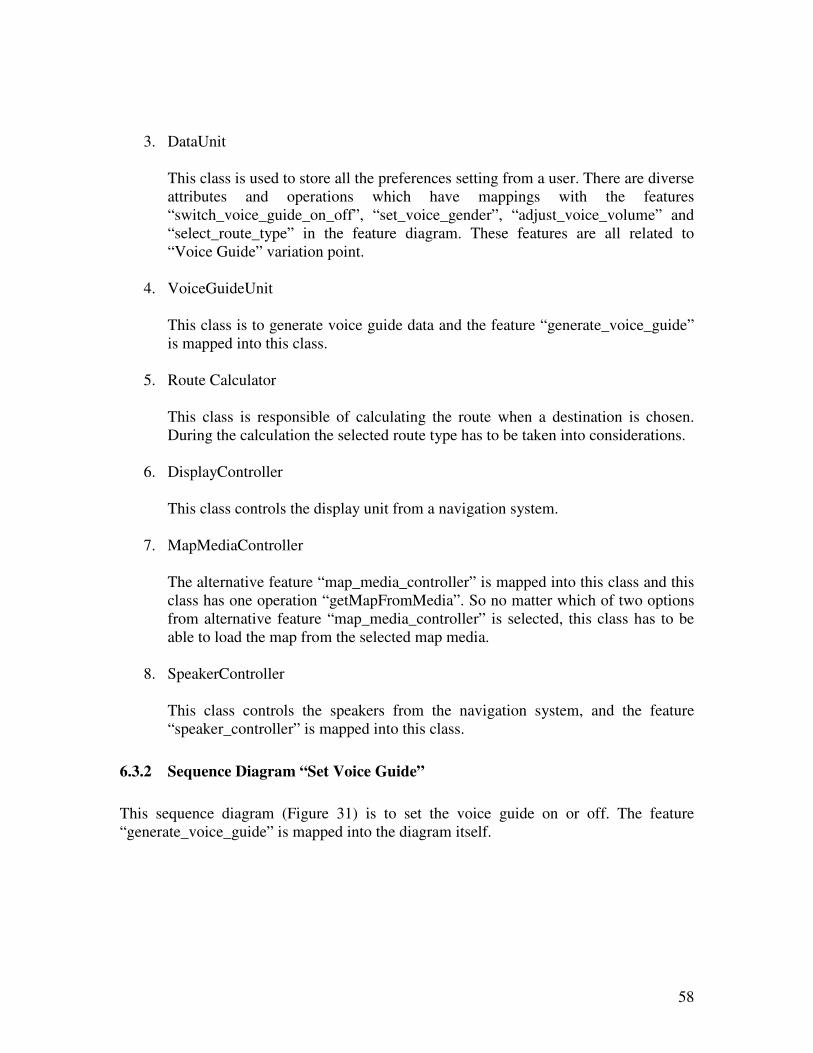
58
3. DataUnit
This class is used to store all the preferences setting from a user. There are diverse
attributes and operations which have mappings with the features
“switch_voice_guide_on_off”, “set_voice_gender”, “adjust_voice_volume” and
“select_route_type” in the feature diagram. These features are all related to
“Voice Guide” variation point.
4. VoiceGuideUnit
This class is to generate voice guide data and the feature “generate_voice_guide”
is mapped into this class.
5. Route Calculator
This class is responsible of calculating the route when a destination is chosen.
During the calculation the selected route type has to be taken into considerations.
6. DisplayController
This class controls the display unit from a navigation system.
7. MapMediaController
The alternative feature “map_media_controller” is mapped into this class and this
class has one operation “getMapFromMedia”. So no matter which of two options
from alternative feature “map_media_controller” is selected, this class has to be
able to load the map from the selected map media.
8. SpeakerController
This class controls the speakers from the navigation system, and the feature
“speaker_controller” is mapped into this class.
6.3.2 Sequence Diagram “Set Voice Guide”
This sequence diagram (Figure 31) is to set the voice guide on or off. The feature
“generate_voice_guide” is mapped into the diagram itself.
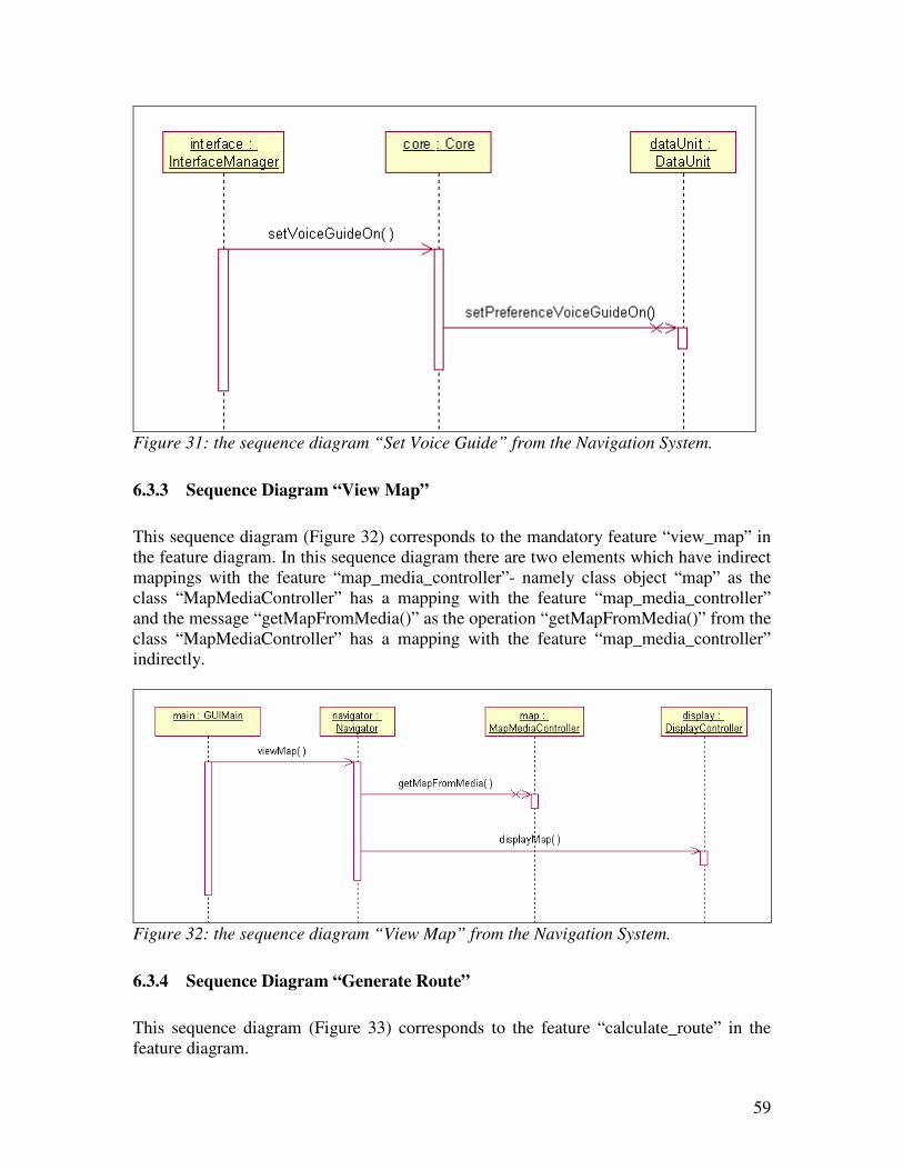
59
Figure 31: the sequence diagram “Set Voice Guide” from the Navigation System.
6.3.3 Sequence Diagram “View Map”
This sequence diagram (Figure 32) corresponds to the mandatory feature “view_map” in
the feature diagram. In this sequence diagram there are two elements which have indirect
mappings with the feature “map_media_controller”- namely class object “map” as the
class “MapMediaController” has a mapping with the feature “map_media_controller”
and the message “getMapFromMedia()” as the operation “getMapFromMedia()” from the
class “MapMediaController” has a mapping with the feature “map_media_controller”
indirectly.
Figure 32: the sequence diagram “View Map” from the Navigation System.
6.3.4 Sequence Diagram “Generate Route”
This sequence diagram (Figure 33) corresponds to the feature “calculate_route” in the
feature diagram.
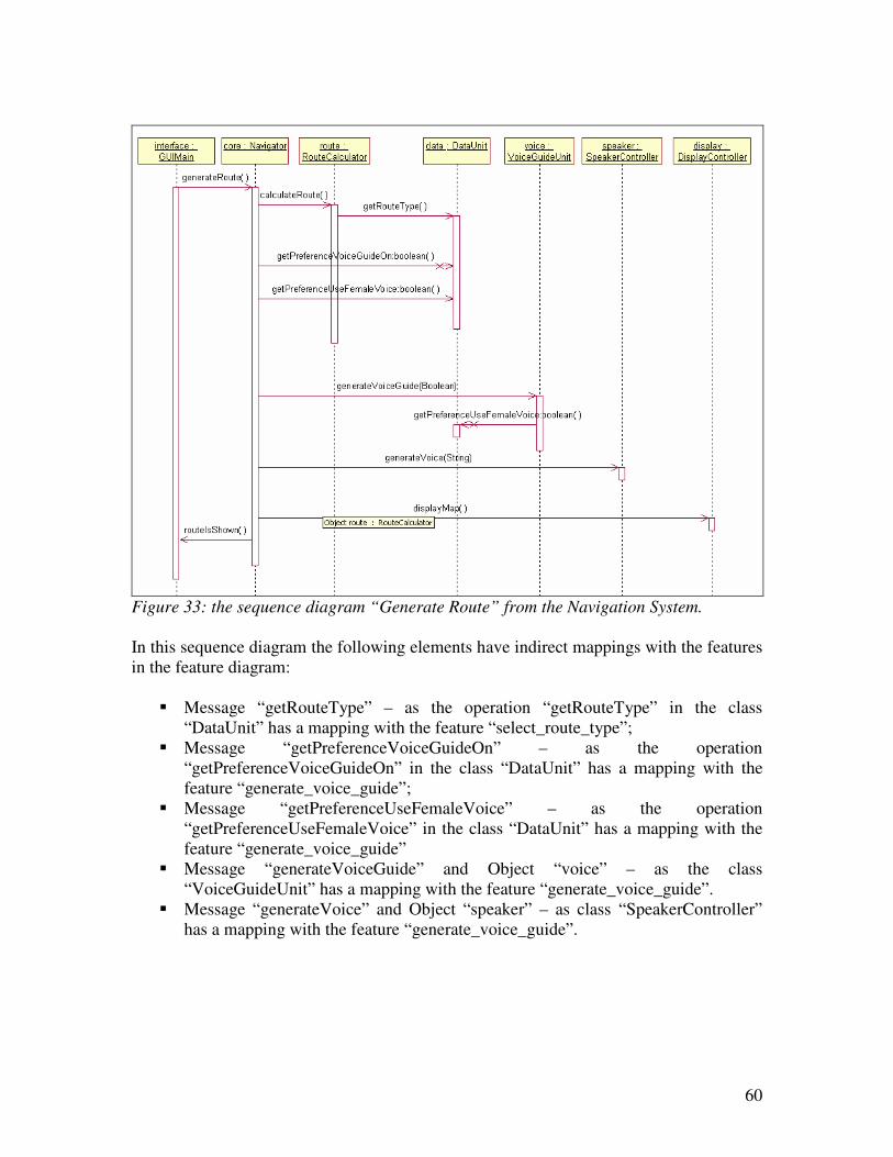
60
Figure 33: the sequence diagram “Generate Route” from the Navigation System.
In this sequence diagram the following elements have indirect mappings with the features
in the feature diagram:
� Message “getRouteType” – as the operation “getRouteType” in the class
“DataUnit” has a mapping with the feature “select_route_type”;
� Message “getPreferenceVoiceGuideOn” – as the operation
“getPreferenceVoiceGuideOn” in the class “DataUnit” has a mapping with the
feature “generate_voice_guide”;
� Message “getPreferenceUseFemaleVoice” – as the operation
“getPreferenceUseFemaleVoice” in the class “DataUnit” has a mapping with the
feature “generate_voice_guide”
� Message “generateVoiceGuide” and Object “voice” – as the class
“VoiceGuideUnit” has a mapping with the feature “generate_voice_guide”.
� Message “generateVoice” and Object “speaker” – as class “SpeakerController”
has a mapping with the feature “generate_voice_guide”.
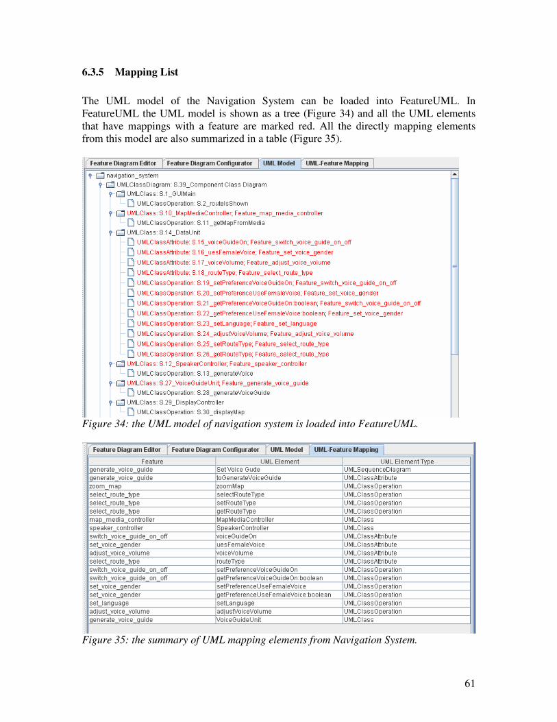
61
6.3.5 Mapping List
The UML model of the Navigation System can be loaded into FeatureUML. In
FeatureUML the UML model is shown as a tree (Figure 34) and all the UML elements
that have mappings with a feature are marked red. All the directly mapping elements
from this model are also summarized in a table (Figure 35).
Figure 34: the UML model of navigation system is loaded into FeatureUML.
Figure 35: the summary of UML mapping elements from Navigation System.
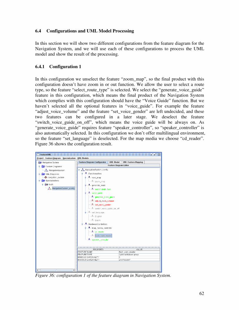
62
6.4 Configurations and UML Model Processing
In this section we will show two different configurations from the feature diagram for the
Navigation System, and we will use each of these configurations to process the UML
model and show the result of the processing.
6.4.1 Configuration 1
In this configuration we unselect the feature “zoom_map”, so the final product with this
configuration doesn’t have zoom in or out function. We allow the user to select a route
type, so the feature “select_route_type” is selected. We select the “generate_voice_guide”
feature in this configuration, which means the final product of the Navigation System
which complies with this configuration should have the “Voice Guide” function. But we
haven’t selected all the optional features in “voice_guide”. For example the feature
“adjust_voice_volume” and the feature “set_voice_gender” are left undecided, and these
two features can be configured in a later stage. We deselect the feature
“switch_voice_guide_on_off”, which means the voice guide will be always on. As
“generate_voice_guide” requires feature “speaker_controller”, so “speaker_controller” is
also automatically selected. In this configuration we don’t offer multilingual environment,
so the feature “set_language” is deselected. For the map media we choose “cd_reader”.
Figure 36 shows the configuration result.
Figure 36: configuration 1 of the feature diagram in Navigation System.
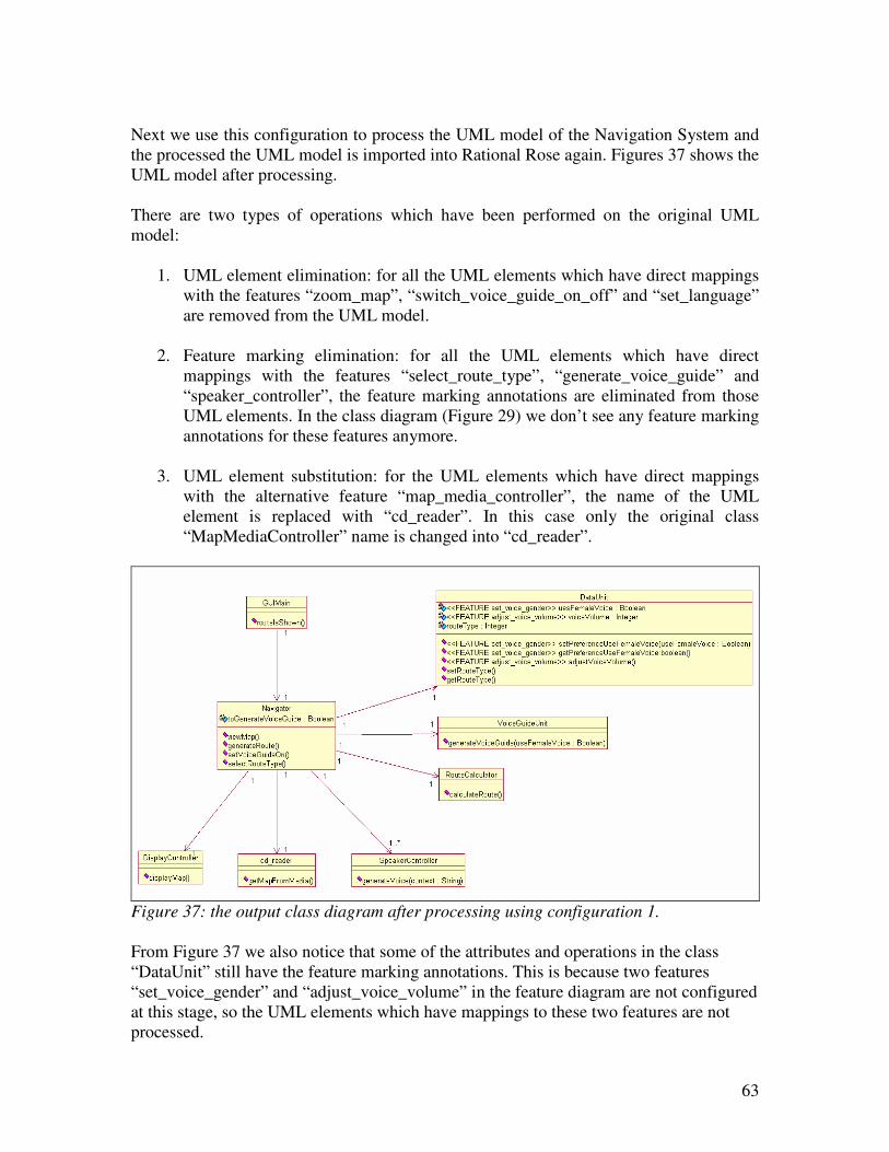
63
Next we use this configuration to process the UML model of the Navigation System and
the processed the UML model is imported into Rational Rose again. Figures 37 shows the
UML model after processing.
There are two types of operations which have been performed on the original UML
model:
1. UML element elimination: for all the UML elements which have direct mappings
with the features “zoom_map”, “switch_voice_guide_on_off” and “set_language”
are removed from the UML model.
2. Feature marking elimination: for all the UML elements which have direct
mappings with the features “select_route_type”, “generate_voice_guide” and
“speaker_controller”, the feature marking annotations are eliminated from those
UML elements. In the class diagram (Figure 29) we don’t see any feature marking
annotations for these features anymore.
3. UML element substitution: for the UML elements which have direct mappings
with the alternative feature “map_media_controller”, the name of the UML
element is replaced with “cd_reader”. In this case only the original class
“MapMediaController” name is changed into “cd_reader”.
Figure 37: the output class diagram after processing using configuration 1.
From Figure 37 we also notice that some of the attributes and operations in the class
“DataUnit” still have the feature marking annotations. This is because two features
“set_voice_gender” and “adjust_voice_volume” in the feature diagram are not configured
at this stage, so the UML elements which have mappings to these two features are not
processed.
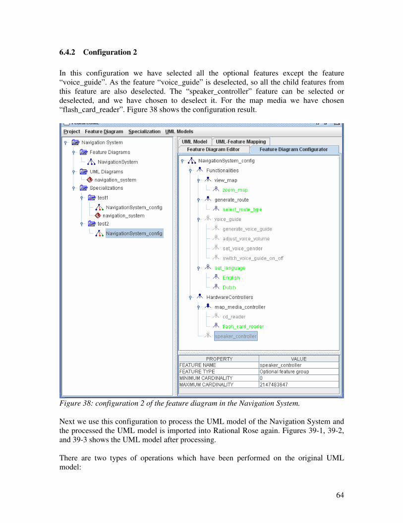
64
6.4.2 Configuration 2
In this configuration we have selected all the optional features except the feature
“voice_guide”. As the feature “voice_guide” is deselected, so all the child features from
this feature are also deselected. The “speaker_controller” feature can be selected or
deselected, and we have chosen to deselect it. For the map media we have chosen
“flash_card_reader”. Figure 38 shows the configuration result.
Figure 38: configuration 2 of the feature diagram in the Navigation System.
Next we use this configuration to process the UML model of the Navigation System and
the processed the UML model is imported into Rational Rose again. Figures 39-1, 39-2,
and 39-3 shows the UML model after processing.
There are two types of operations which have been performed on the original UML
model:
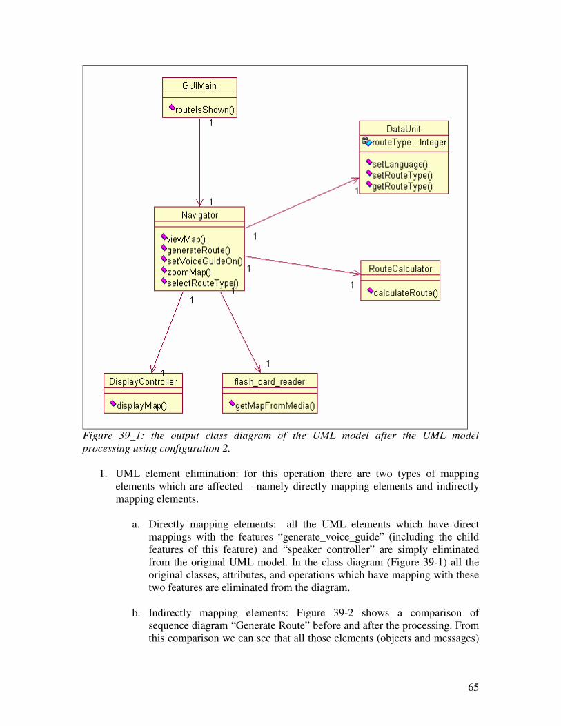
65
Figure 39_1: the output class diagram of the UML model after the UML model
processing using configuration 2.
1. UML element elimination: for this operation there are two types of mapping
elements which are affected – namely directly mapping elements and indirectly
mapping elements.
a. Directly mapping elements: all the UML elements which have direct
mappings with the features “generate_voice_guide” (including the child
features of this feature) and “speaker_controller” are simply eliminated
from the original UML model. In the class diagram (Figure 39-1) all the
original classes, attributes, and operations which have mapping with these
two features are eliminated from the diagram.
b. Indirectly mapping elements: Figure 39-2 shows a comparison of
sequence diagram “Generate Route” before and after the processing. From
this comparison we can see that all those elements (objects and messages)
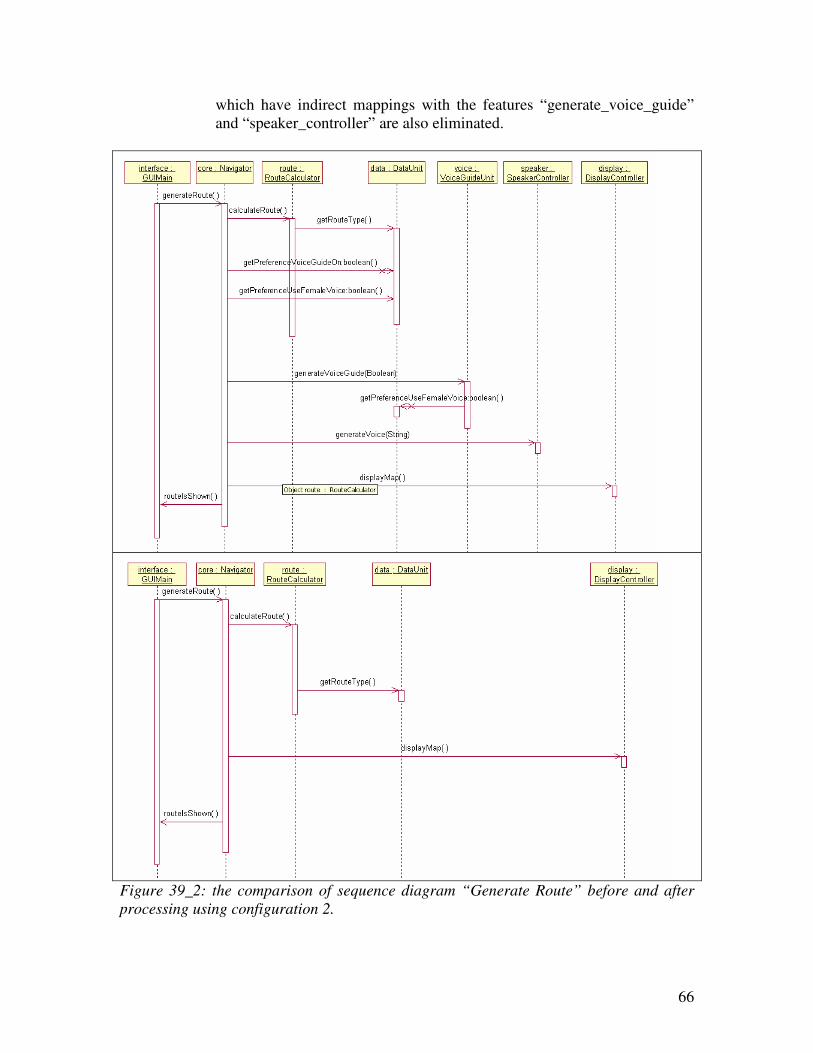
66
which have indirect mappings with the features “generate_voice_guide”
and “speaker_controller” are also eliminated.
Figure 39_2: the comparison of sequence diagram “Generate Route” before and after
processing using configuration 2.
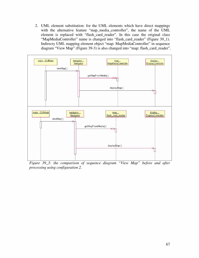
67
2. UML element substitution: for the UML elements which have direct mappings
with the alternative feature “map_media_controller”, the name of the UML
element is replaced with “flash_card_reader”. In this case the original class
“MapMediaController” name is changed into “flash_card_reader” (Figure 39_1).
Indirecty UML mapping element object “map: MapMediaController” in sequence
diagram “View Map” (Figure 39-3) is also changed into “map: flash_card_reader”.
Figure 39_3: the comparison of sequence diagram “View Map” before and after
processing using configuration 2.
68
7 Conclusion
The concept of product line software system development has been around for a few
years. Until now there are still no right methods which support this development process.
The method PLUS supports part of the processing by using feature concepts. In PLUS the
feature model is represented in UML elements; thus the feature model is simply mixed
into the UML model of the system design. This approach has increased the complexity of
the UML model greatly. As modern software development pursuits concern separation, it
would be better to separate feature models from UML models and then make some kind
of connection between these models. This is our initial idea for our method FeatureUML.
Feature diagrams have been the widely accepted candidate to hold features in a feature
model, so we have deployed the feature diagram to hold the features in our feature model.
We have extended the feature ideas with dependency relationships between features and
feature cardinalities. All these techniques help to hold the commonalities and variations
of a product line. The feature diagram can also be configured for a special member of the
product line in stages.
But a feature model will be only a set of symbols if they are no any connections between
the feature model and UML models, and the existence of the feature model has also no
meaning anymore. In order to setup a connection between the feature model and UML
model, we have used the stereo tags in the UML model to make a mapping annotation
between a feature and a UML element. With this mapping information, we can process a
UML model for a special member of the product line. The processing takes a
configuration as input, and checks on the status of each feature in the configuration.
Depending on whether a feature is selected or deselected; we eliminate or substitute the
UML elements which have mapping with this feature. At the end we derive a UML
model which only contains the functionalities which are required for this member of the
product line. The newly derived UML model can be further used for communication
between different stake-holders, code modifications and generations, etc.
Following this idea we have built our first prototype to support this process. The
prototype program can create and hold feature models of a product line, make
configurations for a special member of the product line, load and process UML models.
After experiments with a few examples, we have successfully generated specialized UML
models for single members of the product line. This initial case study has shown us that
this method can reduce the effort and time which is spent on creating individual systems.
The quality of the generated UML models for single member of the product line is also
improved, as with generation techniques we rarely make mistakes by removing the UML
elements from the original UML models.
The current state of FeatureUML only supports part of the product line development
process, namely the requirements gathering, system analysis and design. It would be
interesting to extend the method to support the code generation as well, and then
FeatureUML would support the whole product line development process automatically.
69
8 Future Works
There are quite some future works which can be done to the FeatureUML method; here I
will list the future work items.
8.1 Feature Diagram
1. Two dimensional alternative feature: the current implementation support one
dimensional alternative features, which means an alternative feature in our
program cannot contain another alternative feature immediately. But in real
situations it is possible to have two dimensional alternative features, which means
under an alternative feature there is immediately anther alternative feature. This
can be built in the FeatureUML in the feature. But extra care has to be taken in
configuration and processing UML models as two dimensional alternative
features do make the feature diagram more complex.
2. Feature Dependency: in the current prototype it is possible to have a compound
“and” required (or exclude) relation, which mean A requires (or excludes) B and
C. But it is not possible to have a compound “or” require (or exclude) relation, for
example A requires (or excludes) B or C.
3. Feature diagram correctness checking: when the dependencies relations in a
feature model get more complex, the correctness of the feature model is also
difficult to be guaranteed. It is hard to know if feature diagram contains at least
one combination of selecting/deselecting feature choice so we can make a valid
configuration out of it. So we have to think of a way to check if a feature diagram
contains the right dependencies such that we can make a configuration out of it.
8.2 Feature-UML Element Mapping/Processing
1. Map into more diagrams: the current tool can only map features into class
diagrams and sequence diagrams. It would be nice to map features to other types
of UML diagrams as well.
2. Map cardinality to UML model: even though the concept of feature cardinality
is built in the current prototype, it is not mapped into the UML model and it is
also not used in the UML model processing.
3. Map feature to operation input/output: during the experiment with our tool, we
have found out it would be useful to map features to the operation input and
output parameters as well. Very often an input parameter has to be one option
from an alternative feature.
4. Improve mapping quality: the current mapping is done by hand. Thus when the
UML model is made, whenever an UML element is supposed to map into a
feature, the author has to add this feature mapping annotation to the UML element.
The process is error-prone, especially when we have a big feature model and a
70
few big UML models in the product line. This process can be proved by using
some automatically mechanisms, such as when a UML element is created and
needs a mapping, it should be able to select an existing feature to map to. This
may require the tool eventually to create UML diagrams as well.
8.3 Product Line Software System Process
The current method only supports part of the process; it would be nice to extend the
method to support domain implementation and application code generation as well.
This would require further research on both the method and the tool.
71
9 References
Booch, G., J. Rumbaugh, and I. Jacobson. 2005. The Unified Modeling Language User
Guide, 2en ed. Boston: Addison-Wesley.
Clements, P., and Northrop, L.2002. Software Product Lines, Practices and Patterns.
Boston: Addison-Wesley.
Cohen, S., and L. Northrop. 1998. “Object-Oriented Technology and Domain Analysis.”
In Fifth International Conference on Software Reuse: Proceedings: June 2-5, 1998,
Victoria, British Columbia, Canada, P. Devanbu and J. Poulin (des.), pp. 86-93. Los
Alamitos CA: IEEE Computer Society Press.
Czarnecki, K., Eisenecker, U. 2002. Generative Programming Methods, Tools, and
Applications. Boston: Addison-Wesley.
Czarnecki, K., Helsen, S., and Eisenecker, U., 2004. Staged configuration using feature
models. In R. L. Nord, editor, Software Product Lines: Third International
Conference, SPLC 2004, Boston, MA, USA, August 30-September 2, 2004.
Proceedings, volume 3154 of Lecture Notes in Computer Science, pages 266–283,
Heidelberg, Germany. Springer-Verlag.
Fowler, M. 2004. UML Distilled: Applying the Standard Object Modeling Language, 3rd
ed. Boston: Addison-Wesley.
Gomaa, H. 2004. Designing Software Product Lines With UML, From Use Cases To
Pattern-Based Software Architectures. Boston: Addison-Wesley
Gomaa, H., and D. Webber. 2004. “Modeling Adaptive and Evolvable software Product
Lines Using the Variation Point Model.” In Proceedings of the 37th
Annual Hawaii
International Conference on System Sciences, HICSS’04: January 05-08, 2004, Big
Island, Hawaii, USA, pp. 1-10. Los Alamitos, CA, IEEE Computer Society Press
Greenfield, J., Short, K., 2004. Software Factories: Assembling Applications with
Patterns, Models, Frameworks, and Tools. Wiley.
Kang, K., Cohen S., Hess J., Novak W., and Peterson A. 1990. Feature-Oriented Domain
Analysis (FODA) Feasibility Study (Technical Report No. CMU / SEI-90-TR-021).
Pittsburgh, PA: Software Engineering Institute.
Czarnecki K., Helsen S., Eisenecker U., 2004. “Staged Configuration Using Feature
Models” in Lecture Notes in Computer Science Volume 3154, pp.266-283. Springer
Berlin/ Heidelberg.

72
Riebisch, M., B¨ollert, K., Streitferdt, D., Philippow, I., 2002: Extending feature
diagrams with UML multiplicities. In: 6th Conference on Integrated Design &
Process Technology (IDPT 2002), Pasadena, California, USA
Rumbaugh, J., G. Booch, and I. Jacobson. 2005. The Unified Modeling Language
Reference Manual, 2nd
ed. Boston: Addison-Wesley.
Weiss, D., Lai, C. 1999. Software Product-Line Engineering, A Family-Based Software
Development Process. Reading, Massachusetts: Addison-Wesley.