Embed Size (px)
Citation preview

Eindhoven University of Technology
MASTER
Coupled thermal solar collector and heat pump simulation for improved systemperformancea comparative study of parallel and serial solar collector & heat pump systems for theCzech Republic
van Mierlo, B.P.
Award date:2011
DisclaimerThis document contains a student thesis (bachelor's or master's), as authored by a student at Eindhoven University of Technology. Studenttheses are made available in the TU/e repository upon obtaining the required degree. The grade received is not published on the documentas presented in the repository. The required complexity or quality of research of student theses may vary by program, and the requiredminimum study period may vary in duration.
General rightsCopyright and moral rights for the publications made accessible in the public portal are retained by the authors and/or other copyright ownersand it is a condition of accessing publications that users recognise and abide by the legal requirements associated with these rights.
• Users may download and print one copy of any publication from the public portal for the purpose of private study or research. • You may not further distribute the material or use it for any profit-making activity or commercial gain
Take down policyIf you believe that this document breaches copyright please contact us providing details, and we will remove access to the work immediatelyand investigate your claim.
Download date: 21. Jun. 2018

2011 4924 BWK
building physics and systems
E H If
Coupled thermal solar colledor and heat pump simulation for improved performance A comparative study of parallel and serial collector & heat pump systems for the Czech Republic
CZECH TECHNICAL MA1 UNIVERSITY IN
PRAGUE rUle Technlsche Universiteit Eindhoven University of TechnololY
AUT.,..:
B.P. van Mierlo
DAm 11 October 2011
Where InnoYllion StiltS
TU e Technlscnt Universiteit Eindhoven Un IversTty of Technology
(
Coupled thermal soLar collector and heat pump simuLation for improved system performance
A comparative study of parallel and serialsoiar collector & heat pump systems forthe Czech Republic
Graduation thesis for the completion of the Master's program Building Services at the Eindhoven University of
Technology.
Project conducted in collaboration with the Czech Technical
University in Prague, under supervision 01':
prof. dr, Ir. J.LM. Hensen, Unit Building Physics & Systems, DepartmentofArchiIU/Ur?, Building. & Planning. Eindhwen Univtrsiry of TtchnoJogy, The Nttherlands
Doc.lnll'. T. Matu!k" PhD, Department of Environm ental Engineering, Faculty of Mechanical Engin eering, Czech Technical University in Prague, Czech Republic
Ir. G. Boxe .. , Unit Building Physics II S~tems, Department of Archimclure, Building, & Planning, Eindhoven UnMrsity of Technology, The IIetherhJnds
CZECH TECHNICAL UNIVERSITY IN
PRAGUE
In ,ol, l>oroti"" wi,l"
Technische Universiteit EIndhoven University ofTechnology
Abstract
C"-ii nl "' ..... 011 tl>< "OJ'" cI<. 1 witn on OTrY h .... "" ..... 10<.$0. ",du<in~ ' ' 'TrY ""0"'''' pt"'" .nd ... , ... ;,,~ tho u'.
of ,.".,... •• 1< ,nOTrY _« ••. '" tl>< built o";ro.",""'- ",!"Iot""'. ond porbli< _"''''' .. I" ...... tho ... of ",.tolnob1o
''''''SI' in tl>< ~Iopm .nt of ""'" n"".inc ~joct ...... , tho p .. t de<ad .... Eof"". Pll1;';ulo"". ~r"" nd·.o"n:. hoot I>"mp
.~t."U and IOlar (ol~lo" Iorm o/t..,-u .. d oltornoti .... to Io .. i11u, 1 .~Ie". in u,. ~in! 01 , pit(, I><. ti"! . n<! hot
" ..... fof d" .. inj;1. 80Ih tIM>< <\,<t. m. ha .. UFO" .nd """n, id .. loT ""ltin, !<"MTII;"n. Sobr<<>iI<cloT pim " ' • • 1< 10
I"<M~' tn. hirhor '''''poIltU". _~..t lor hot "II", I"odud;"n. !>oJt '" dop<f1d, nt on tl>< ... i!ob;lity O/,.,Ior ",ldilli,,".
r.qo I,,"~ on od dlt",NlI .~It.m. ~"'" ".;. ... ,,<0 1>0"1'" m i>' (On 1"_ 0 IlIb 10 lUPI'lv of . n .. ~. Out tho hilf1 .. "., po,.I, '"
,,,,,,,I~ of hot ... tor _~ tholr o/1klon<~. F<If ,heI. '"""'" tn •• ~tom. lro 0_ uHol in ((Imb inl/i,," with .><h othor.
0"" solution I, • • 1,.1" .... id. ,,,,,blnatlon 01 ,ho .~It ..... "",1.11. w.....". _ OHmoO ~ty.!Tkiont. C..,tHoinz
tn , ',,",T ,oIo<tor ond h.ot p-ump in ........ tl>ouchtto I",p'_ tho .lIId."",. B~ u.ln~ 'ha $Olar (oilKtofto , .. _at. tho
I round·' '''''T'' tn , Ufo .~n of tho 'Y'"'' "n .. . ><tend ..... Throul h noooIo-lll nl • nO "". po,l"n '0 0 ~r"",nO·.ou«. Itoot 1>"'" P ".to rII tho porfor""nc. 0/ ,ha Yf'" rII. I . ..... n:h<od. Tho
, ,,t.m , IT. ,on"""ed to hoo'in~ !>oJfIoo". lor op". hootin,Ond 00''''';'; hot .. "" to ",,""lot . .. <yinl ,,~ I"'~.
",t Io,eb. ro.po<ti .. ly. T11. ""o'",1s oIth • • ~" ... , I .... "ion In ou<tIl .... ~ thol the OIIpp1y 01 . -.-, 10 lhe hot·,,"tor I>u~or
ha, ~T""ity "" ...... l)' ouPI*Y I<> lho 'po<. h .. tin~ 'u~or. T11. porformln<. I . . ..... 00 .,101 'I~"." porfo"",,,,,
indicator.; to. ,_"nt 01 I><rfumon<' (eOf'). lhe ... son" porforml"". Io<tor (5 "') on<! On """'l)' offi,lon<, rotlo. T11.
, ,,,,, 115 show tho! tho COP of In , .... P'Jm~ Is ;",prO'lod loT lho " ........ ide OM .. rill.~.t.m I, ,omPlrilon tho ~rO<Jn<t.
"""T<I .... p"rop .)'>"' •. for lhe side·by "do .~t.rn tlli. Is , ... 0<1 bV tho sol .. ,001o'lor OIIpptyln,1 poortlon 01 tho '0< ".tor. Th . """ ... io WPfof t .. ..,i. I."t.m Is du. to hishor ",lot t.m poT,t", .. oIth , ... t P'J"P on tho _'" .id •.
Ouri,,! wintl! month. tho 5Pf v,,'" .IIShtl, lor 1M .~t.'"' . .... sot. ~"dIOIIoo lwo .... in lho .u .. m.r. tho 5~ lor the
.1d<·l>r-sid. 'Y''''''' ,i .... foT In .... "'I')'>tom tho d""'"tion I,om lhe 5Pf lor tho !ro"n~.,,,,,,,. hoOi ""lOp .~.t.m Is
. lnim, L "",i. din. .. n(O ;;., in tn .l"t tn , t d .. inS poriod, 01 ,iI ' ',,",T ~rodio'io. the ,Id<.by-.id< (oIl<,l<>r <0. fU rKt.",
"ithout ,I>< M , t pump ... duci"!l tl>< .1.<t,kll_ input
Soth tl>< COl' ond SPf cIo not pr""," "f""",_ , t.out t .. 1I.dion of ..,10, in. dill;"n u..o 0' the . mount 0/ """ .. , tion
01 tho pound. T11. ,norl)' . ffld. n 'Y rotlo d i,iO .. ttl< '''''WI' us.d fo r n , IIi nl . Oot ,..\<, ond ",~ ... ,.tlon 'S' ;".t the '_!II' .. ,liobIo for "". Thi •• 0-, "" tn .... , ·by·sid •• Yot ... •• rotio Is only 80"", «Imp"ed to LlII 01 tn, lI'"""d·,,,,,,u "" t
pump .Y" .... . pl.It • '7'''' i n u.n. fof tho ,.,i,l.yoto. . Th i. i mp,..,.,..", .. t in onor!!\, o!ff, "",y io ,"'"ted "' the ~ ... ,.
01 tho """'I!. (TOWIll tom I><Til t . ... rod ud nl it fro .. . o. J"e . M .. I <!Hoy for tl>< !",ond·"Hn," n , II pum p ,y,te., to , o.1"C
Ior'ho .oriot 'Y>!' • . """ <!Hoylor tn . >iik--by·,iO. 'I"t.m i, 0.'5·C. T11, ""ult>.how 1I .. t t .. , id ... by->id. "oI.m d"", not
;", P''''''' OIl ttl< ""'!II' o!ff, i .. 'Y 01 the I><,t puRl P , y,tom. tilouih prolon!i n I tl>< Iff< >pi! n. """ ",e ,!!\' o!ff, "M, 0/ th, , eri.1 .~_ I ... impr""" ... nt t. tho I><It I>"mp 'l"t.rn. bH...". ,n, frxtioo lor sot..r i""ill;'n i. in<TO .. od duo I<> oIlmty to
p,oYIcI< ,,,,"'TiI'Io. oI"' l round·,oUl".

Technische Universiteit Eindhoven University of Technology
Foreword Th~ thesis before you is tne culmination of almost a year's wortn 01 research. During-these last 11 months I hive been wo""ing on my graduation project in order to achieve i Master's in "BuildingS ~rvl c~s" atth e Fa cu Ity oft h e Built [ flvi ro n me nt at Ei n d n oven U n we rsity olT e chn ology. Whe n I started my education In 2003, I was unc~rtain aoout whether or not the field of Building Servicei would suit me; I only kn~w that I hid a broad inte rest in technology. The Bache lor "Installatietechnologie" provided me with a diverse education In different tech nkal artas.
Duringthis time, I developed two main int~~sts: one through ~ducation and th e other through my internihip. The projects and classes during my Bachelor phase got me int~r~sted In the dev~lopm~nt 01 sustainable and energy·effid...,t buildings and systems, which I pursued further In two of my Ml iter's projects. Durins: my internship, I became fascinated by the way consultllnc1es and oth~r companies in construction oper.lted: a way whkh in my eyes seemed old·fash lon~d and d~ncient. tt hecame a ",uree offrustr.ltion, leading me on a starch to nnd a project whkh allowed me to dig into the reasons behind this. Such a proj...:! waS drawn up and was to be a combined Master's and graduation project. Alas, it was not meant to be. During the finalization of the report for my Master's project, it hecame evid...,t that for ",asons beyond my contrOl, it waS no longer possible to extend tne project into my graduation.
Without the luxury of time to develop a new graduation project, I returned to my oth~r inter~st: sustainable buildings and systems. By chance I stumbled upon a project of whkh the goals were already more or less defined. In addition, it allowed me to spe nd a semest~r abroad, which is something I have always wanted to do, but never got around to. Within two months, my project proposal was approved and t started working on my s:raduation project in N<wember 2010. After moving to Prague. wh~re I spent lour months workins: on my project, it is now Octobe r and the work Is finished. All that ",mains now is to thank tn e peop~ without whom t would not have made it this far.
First of alii wish to thank my supervisor Jan Hensen, who assisted me in the start-up of the project, helped making the arrangements lortne period t spent in Pras:ue, and provided /eedbackthroushout the project, all desplt~ his busy schedule. During my stay in Prague, my supervisor TomH Matu~ka, was Invaluable in the deve lopment 01 the simulation mode ls. Especially duringthe last month of my stay. we met as often as possible in order to assu'" speedy completion 01 tne simulations. The last sUj>ervlsor I want to thank, Gert Boxem, has provided me with his insignt into field 01 heat pumps and assuring that I did not lose sight of reality, when twas locusing too much on the model, instead of the probl~m at hand. Special than);;s are in order for Robert Krainer, who helfl"d me ",lYe th ~ problems I encountered with TRNSYS, and Chelsea (orkins, for proofreading my tnesis.
I also want to thank my employer. Valstar Simonis, for providing me with the freedom to tal<e a four month l~ive and spend time In Prague; D time whkh n~xt to being a valuable addition to my education has bMn an amazing exp~rlence. Furthermore I would like to thank my friends and fellow students who have made thes~ eight years so much more than an education, and provided me with the much ne~ded distraction during my graduation.
Last, but in no way the least. I want to express my gratitude to my family, in particular my parents, who have always suppurted me in my choices and gave m~the freedom to pursue my desires.
Peter van Mlerlo October 2011
CClu p!<d tn . Im . 1 ",1M ,01" <1 .. , r><i n .. t pump ,;muillti "" fm impr<l'i«l ')'>t.m ~rml r>« I iii

Technische Universitei\ Eindhoven University of Technology
Nomenclature Symbols , , , " , , , • , , • o
, lItldl
Gru hymbols ,
Sub5<:ripts
'" • ." • , 00. ~ ." "' ,~ '"' ~
,~
~.
min
" ~, ~ .. , '" .,.. , "
UN 1m'] ~peo;ifi~ heat IkJlkgK] ,.,.rec~.n foetor [-I .... er .. heat 10 •• , ,,,,ffic ient [W/~I indi<otor [-] thor",al '<>ndLJ<tt;jt~ [W/m~]
lens!h 11'111 ., ••• fIow [ki ln] num~r.I[-]
powe r IWl .., ,,gy[WJ total hel l traMler [kWh] cold wate r lemperoture I"CJ h nl tr.., .Ier coeffio;i enl [W / m'(] internal ,ontrolle, sisnll I-J internal ,ootrolle, sig ... 1 [-] Yolume [m'] ,ontrolle, input sign", [-J <<>ntroll..- oulput .i r n.l H temperoture dlffe,..,," I"CI
,atio between hell PU"'P ,apl<itv and Mat load [-I "ffecti .... ...... [-] efficiency [-] ~Mlty [ks/m'] ~m e [. ]
b~"..,
amb .. nl .uxili~ry
bone <oolin! .N-..,., ~ti' !>tit wile,
" m,l..,cy aI.dr;, .. timlte ..,ter1ng wate, temperatu,. ground n.", ~,hln~r
he'tpump intorn.l. indoor lelYi nli' water ternperoture maximum minimum nomiul po5i~on
.01 .. ,<>I!e<tor set pol"t
'P"". he"lnE specific: tou l
~'"

Technlsche Universl telt Eindhoven University ofTechnology
Abbreviations
"" ~It<l! '" I"' ''"""a"n
" Czem ~ep"bll( , ... dom H tic. not water
"" £Urop"" Perform."", 0/ hl!dln,. OiroctiYe
'" £UfQ~n iJr1;""
'" IrooM h"l e.uN.nrer
" ... !fOfJnd-so",co lIN! pUoIIp
~" pMlo..,Uik;/th_1
" ..... '<oll.uor SC-6SHP ..... , colle(\OI .. 1'''''''''·'''''<1 hut p ... p
'" ",,"co _.
,~ ........ 1 peo(or.,IIn<l ~OI
"'" So,," loti"' ..,4 Ct<tlllcatlOll eo..._ Y-G ~. otnical.IJ" """! hut HlNn.er

Technische Universiteit Eindhoven Univers ity ofTechnology
Table of Contents
Abstrllct Foreword MomencliltuJe Abbreyiations
, '.' '.' ,., 2.)..1 2.].2 2.].]
, ,., p ,., ,. ,., • , ,.,
Introduction Previo~swork Reseal'(:h description
Methodology Reference building DHW ronsumption Altern;ltive hut pump systems GSHP system PanUel SC-GSHP syste .. SeriaI5(·GSHP system
Results Coefficient of performance Seasonal performance factor Enern' efficiency ratio Solar collector performan", Ground hut exchanger
Discussion
Conclusion Future reseal'(:h
8lbUo!!raphy
Appendices A Reference bulldlnl" chancterlstlcs B Helt pIImp chaillcterlstlcs C Dimenslonln!! method fortheV·GHX D TRMSYS Inputdlta D.1 Ground·source heat pump system D.2 Panllel solilr collector & !!round·soul'(:e hut pump system D.] Serial sol" conedor and lI'Ound-source heilt pump system
;
'" , " , , , , , , • • , , , , " " " "
" " "
A , , , , 5

Tedmlsche Universileil Eindhoven University ofTechnology
1 Introduction
(Umlte d\inge , inc. easlnc poIlullon, 100 enelCY !oUpply insewrily - .U of whldll~ I bunclanl In e .... mplf: - hIw:
forcibly chinp<! 1M WI.., Pt'OClle Ihlnk .boo.!l ~ supply. II Is no !antI!< I qUHlIon of whetllt. Ot nol U$!
of ,,",,_able e n«n HUtCU is ne<eswly 10 prQ¥ide ... Iiable - ' IV supply fur future yMrs. Develllpmtrln Ihat haw lakftl pIKe ' Ince lilt ttBo's ~ IohowrI .... 11 .......... bIe e nftsy !oOUfCU • • t. ne<eS$lty /Of _Ialllinl . r.omintlOU§ and sew .. enerD sup.,..,. Ren_4ble enHD SoIIUtC~ cont .ibute 10 the solutions fo. Iht afoflHllenllooecl p.oblems by [()nlribull nl 10 .eclu<e clepena,""tY on fossil fuels.. dimlni~inl ( fftnhouse (lIses, and Inc .ust", energy su pply sHu.ity [I I .
Rising fuel prites Ind tHI,,~Io,kll deve lol pme nlS have mlde renewable energy systems In Honoml ca ly viabl e altem.ti~ for fossil f~ls Ind ltI"\etlJY produced by them. The last dHlde alone has shown. tenfoKj Increase In th e instlilled ca pacity oIrenewlbole ene.cy systems [21. which is not OIIIy du e to shrln klns cost$ and In creased efficiency, but certa inly also to potttlcil efforts.
The Kyoto p'otocol, which alms to !ecluce e.haust of greenhouse gUll, has,lYen Intentlve for many countries to rethin k their energy pOIk l". With in the tur~e. n Union (EU). mony inlti l tIv .. Mve!)ee l> QUt forth to reduce energy consumption I nd IrI(ftUI the number oIlenl'Wlll>l<e enHgy syste ms in order to Dc.ease tmlSSfons of ~nhouse
gases. Amoopt olhers, Ihe Ellrope. n Ptrlorm. ",e of 8uild in!s DirKlM! ((PDO) looks 10 ,tdlKe tilt e nergy COI'l!oUmM by tile bWlt fftvifOnmtnl . Sinct housellotdl "'thin the EU I{(ounl lot . 1m0$! • <lWlrttf 01 lilt energy COfl!oUmp!ion, .educlng _flY (onsumptlon In 1111$ sHtar has s ignifiuonl innut nee on , reenhouse tmlssiIIM . nd lI1e """ of fOSsil fu~s Ill.
III rKftlI 'fN'5, 1M desi&n ' fqulrlHllen1S Ie . lI1e prlm~ .. y enelb' consumption 01 d ... llings has betn r;r.dic~11y
reducPd, m.a k.l "l it diffio; ult, If not ImpOSsible, 10 meet the requi recl ~~s usint on ly a (omb l""tion of cenmudion musure:s Ind fossi l f1re~b:ased hNtln. SySlIHllS . Ih1s tr.s 5et In motion a t ransiti on 10 . llffl\lti ... enK!'! sylttmS ... t hin rIomo:stl c const rl1(tlon. ",,,t pump systems I na so la r collHt"" (S<l5yst~ms In partlcull r form In often ·used alternative to provide hut ln, and hot water In dwellln!! as they redlKe th e un offossll en.rlJY sources.
Heat p urn ps as well u sola r collect'" 5 h live d owns ld es whe n it comes to energy seneratton fOl h~attn,. So lar collectors tend to provide hlZh te mperatures, but the avalilibility of solar e nergy Is Intermittent . tn addition, Ihe amou nt of solar energy Ivallable Is It Its lowest when the heat Iollds are high est. OUe to tltese Issu es, soht. coiletlors ~qul,e ...
itdditional h eat source (41.Heat purnps lit Ible to prevlde • st.tble supply of erlK!'! throughout Itt. ~lIlnd provOde highft effi <iend~ at tn-. teml""flIlUI 6 , makinsl hem "i!fY uso.fuI for IIoor heatin! am olttft low'lem""'flIt u"~ he;o tln, ~Iems. Ho-ve<, Itte production of domostlc hoi .... Ie • (OHW) requioes higher temperatures, causlns .... e etfIcltN)' oflht heat pump to (!rop 151. 'hese dr;rwbadts I re SO_ 01
the reasons the Intel'H1 in combini" . soli, colleclors .1Id heat P":IIPS inlo a single system hiVt' bHn p l"lng Inttre $l from both the professlenal and iKl<lemit community.
1.1 Previous work
Research into the comblnecl use 01 seLa r cl)/Ie<tors with hut pump svstems has been around fer mort than 55 yelrs [61. Research performed In Ihe Ia$l two dec.des focuses often on the examination 01. slnRI. system 17: 81. vlfi.latlons on a specll\c system con"gu ratio .. [4: 91, or on optimizing. single system upect [1 0: 111. Studies pe.tal .. to experi menta l setups, often to validate numerk~1 modelling of <o mputer models [7; 1~1. The slmulltlons 01 h8at ~ump ~nd solar collector systems are often used 10 usus the viability of ~ system in different climltIc conditions II); 141. Rased on the research r~iewed, the m~Jor1ty of researc.h f<><u"",s on ~xami""tion of diffe .. nt conllrulltIons of and purpo5~ fo' ""lar coilMor and h""t ~ump s ystem s. A study j u~tajHIsing the performance of a he;r.t pump system "Iainst ~ heat pump combined with a SOW collector wu not follll d; this study fils tnat .. idle.
1.2 Research description
This r ...... aKh r.onWsof a u""f'3fl1live ~im uLa!1on of .... ree IItII pump syst ..... s supplyine spilet h""l in! a nd OW"" for a """",,,et building in PIlIelft, ClPch Republic (Cl).
With ' ''!'Ird!. to Ihe !oOu. ce for Ihe heal pump, both a i' I "d ground ire viable oplio"" when combini"l the hfSll pump wlth a selLa r colleclo •. The location of Ihe stuo:ty &( Iuoo a n iir SOUKe Mat pump as a viable ""lion, due 10 comparably Ionl frost periods in (""tral Eu.ope ['II. Th e fi rst medel consists 01 a grouncl-!oOu. te hut pum~ (GSH P), while the sHond model adds" sola, Colle<tOl in pa rallel operatio n wilh the former system ['51. In the third s yste m, the sella ' col~ctor operates in series with the GSHP.
Systems having a solar col lector to regenerate the ground, by passing fluid from the collector thrOUlh tM soil, from which the heat pump directly extracts ene'!Y. are viable lor heatin!·dominatecl buildings [14: 161. Addltlon.lly, the operation 01 the solar Collector in series with the GS HP <ause the system to ~ less sensitive to mcdl"C~tlol>s
, 0 .. to lad ", . ,oft ...... ow l<ll 'l rot ,"I c .... 1Ir- ",, ~l< • • 0."" , .. ,,'"'''' t..Jdinl .... L!><Cl IoT 11\. 'inlulltion<. '" ru ,,,., ,, rn. boll> 'ountrfl .... ';"ilor. ,"" "'- not inftu ..... t ....... It •.
0Nr>Ie<I t_ot ..... <-.: ... ~-.tpu"'p_ti ... fo<i"',.-._ ~" .. I.
Technische Universiteit EIndhoven University ofTechnology
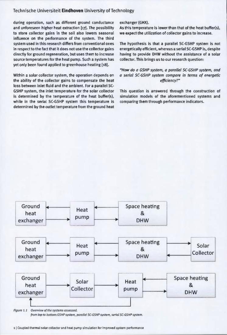
during operation, suo. a~ different ground conducl~n« and unforeseen higher heat extraction [171. The pos~ibility to store co llettor gains In the soil also I~rs seasonal Infl uence on the performance of the system. The third system used in this research differs from con~entlonal ones in respect to the fact that it do~ not use the collector gains directly for I'0und regeneration, oot uses them to increase source temperatur~ forthe heat pump. SUo. a system has yet only been found ~pplied to greenhouse heating [t61.
Within a solar collector system, the operation depends on the ability of the collector gains to compensate the heat 1055 between Inlet nuld and the ambient. For a parallel 5(· GSHP system, the inlet temj>erature for the solar collector Is determined by the temperature of the heat buffer(s), while In the serial S(·GSHP system this temperature is determined by the outlet temperature from the &round heat
Ground heat
exchanger 1---->;
Ground Heat
heat I exchanger
pump I
[ - ~-. ..
Ground Solar
heat Collector
exchanger
f '4/<Jrr 1. 1 r:w.M .... o( 'h • • "'''' ... ",,,,,,<d.
exchanger (GHXj. As t:l1i~ temperature is lower than that of the heat buffens), we expect the utilization of collector gains to Increase.
The hyt>Othesls Is that a parallel SC·GSHP system Is not energetiGllly efficient, whereas _ serial S(-GSHP is, desp~e having to provide DHW without the aSSistance of a solar collector. This brings us to our research question:
MHow do a GSHP s~tem, a parollri s(·GSHP system, and a strlal SC·GSHP system compa~ in terms of entrgetic
efficjtncy?~
thIs question Is answered through the construction of 'limuiatlon models of the aforementioned systems and comparing them t hrough performance indiGltofs.
Space heating Solar
& DHW
Collector
- -
Heat Space heating
& pump
DHW
I {rom "'P '" 1lOO"""G5HP'I" ""'. p,,,,,f<l5(·G5I/P '''''''''. w rlGl5C·GSHP <1"""''".
Techllische Ull iversiteit f:indhoven Universi ty ofTechnology
2 Methodology
The ~mu latl o n mod~5 of the helt !)Ump systems consist of a supply and demand side separated bV hNt buffers. Th e de mand 5lde 15 a 5impliiled repluen\.'llion of a dcmestk tlu lldlnr with a DH W 5ys te m to le-p re5.nt varia ble and In5lantaneol," lnar:is, r<'.5pKti.-e ly. The $\l~ 1y side (omp<i sei of the three c.5HP sy5lems men1 i!)n"" above.. This cllapt'" dese. it..!; the physical charut",isoo of the ~'"" as well as the mo~linl and restrictions.
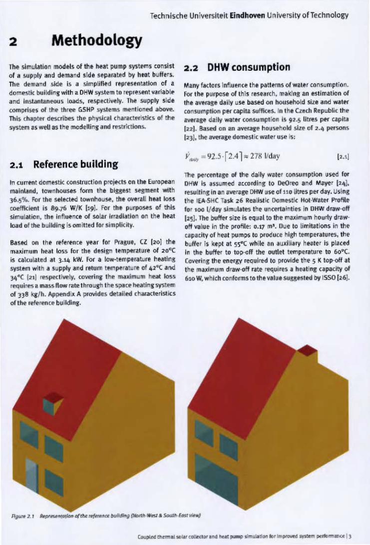
2.1 Reference building
In currl!"l1l domestic COO5lrUC1ion projects on the European l'IYinland, tow nhou!.es form t he bluest 5etmlMlt .,.;th J6~'lI.. For lhe .\eIKt"" townhouse. the _ r,U heat loss CO<I'flkitnt is 89.76 W! K Il91. For the pUl"JlOHs of this simulMion , the Influent:e of sol.u irradiation on the heat load of the bulldinl is omitted 10. simplicity.
Based on the reference YMr for f'ra, uI , CZ 120] the ma;<!mUIl heat 10 •• fo r th e desi gn le mp""ture of 20"C is calcullted " 3.14 kW. For .. kroor·tem pu ature heatln!! system wit h .. supply and return temper. tllle m 42'"C alld l'I'"C 121) '6pt<t""'ly, <OYefini the maximum heat 1M, requir61 -ass flow rate thruul h the 'lMce !>utinl system of 338 "" h. Append ... A I'«Mdu detailed chanc:teristics oH he . t le .... ce bllildi nr .
",..,. 1. I
2 .2 DHW consumption
Many factors Influence the patterns of watf r consum ption . for the purpose of this resta rc h. making In estimation of the awrage .ui ly use based on hoosthold 5ize and ...at'" conSllmptlon ~H "'Pita suflkes. In theun bpubli< the _.~ d, i!v watH o:on5Ulll9tion i~ 91.S lit~ per Ciilpita In l. Based on an aver.tK ~ household si~ 01 2.<\ ...... 5<MIS 1231. the lI'o'eI"ale dome5lic water use Is:
Y_ .. 92.5· r2.41"" 27K Vday [2.1)
The pe rcentare 01 the di lly water COIIsu mption used lor DKW Is fi$\lmed atcordinr to OeOrec I nd Mi.ye r [;.41, .esulllnr In I n IYl'rare DHW use of 110 ~ PH day. Uslnl the IEA·SHe T. sir 26 Realistic Domestic HoI,Wate< Pr"ofh lor 100 Vol.., simulates the un(f!fUoilllies In OIfW d~-olf
)zsJ , The buff!"< size is eqUlI to the muim um hourty drlw' gff YII\u ~ In the ~ofile: g.17 m'. Due to li mitations in the t apatlly of heat PIIm~ to ~oduCf high temperatures, the bufhi r 1$ ltept at 55"( while an auxilia ry heater is placed In the buffer to top·off the outle1 temperatu re to 6o"C. Cov",lnr the energy requi red to Pf<Wide IMe 5 K top·off . t the mulmum driI'W·ofI .. ~ requires. hu ti,,!!, n padty 01 6to W. whiCh (onfoom~ to the v.tut $\lUesl"" b¥ 1550 1261.

Technische Universiteit Eindhoven University ofTechnology
..., .. Remarks
Building Temperature Level Controlled Single lone Model lYPEl2C
Thenn05ti1t Heating Mode Aquastat TYPE2-AquastatH Control band 20tl.5 OC
Tob'" 1.1 fIt",*" I> ",."j I<x tIr. r<pm<""""" {o<11>< ~"!lUbvilding;" 1liii51'S
Element
DHW profile Generic Data Reader
2.3 Alternative heat pump systems
We investigate tl1r~ different heat pump systems in this study. Th e refe rence system Is a GSHP system as It Is
appli ed In today's construction proj&ts. As th e system Is appl!ed to a dwelling, no cool!n! is used due to the already hIgher Investment compared to a conventlona l new home,
wh ere the used ohentilatlon heat reccwery is the standard. In the parallel SC-GSHP system. a t hermal solar collector is used next to the GSHP, working Independently of each
other. Both supply energy for space heating (SH) and DHW. The last system, the seria l SC·GSHP system, uses the the rmal sola r collector to Increase th e Inlet temperature fo r
the GSHP directly. Th e Y·GHX Is regf'nerated th rough higher retu rn temperature from the GSHP and directly by using collector gains when the heat pump Is not In operation.
2.3,1 GSHP system
Heat pump systems are not designe<! to cover the peak load of the building since this load is only present for a small percentage of the year. Instead, heat pumps are designed to COWr th e heat load fo r 90% of t he time with an auxiliary heater to assist for the remainder of the time (see
Figure 2.2). In order to cowr the heat load of the reference tluilding with the heat pump for the require<! part of the year the heat pump capaci ty is determined to be 70% of the maximum heat load [261 .
o -Tone [hI
Component Comments
o6DhwoOl.txt
Equation mDHW _ DHWprofile
Tmld - 15
Th e heat pump a~d auxiliary capacities are:
PH~ = 0.7·3141 .6", 2200 W
p.<H._ =0.3· 3141.6 ",940 W
The mass flow through the circuit between the heat pump and the spate heating bu~r to provide a 5K temperature difference between supply and return temperatures is [27]:
2199.1 2 - = 0.105 kgl~ [23]
4.186·5 .
Th e si~ of the space heating buffer is c~lculated to assure a one hour operation time for the heat pump ~t maximum capacity:
v = P H1· · T = 21 99. 12.3600",378 1 ~ pc·tlJ/U" 4 ] 86 ·5
The source of the heat pump system is a vertical ground heat exchangf'r (V·GHX) , chosen fo r Its applicabil ity In urban areas. Using a heat pump with a deSign coefficient of performance (COP) of 5 (see Appendix B) the design
capacity of the Y·GHX becomes:
P- =P. COP- l = 2200 5- 1 =1760 W GHX H' COP 5
The circuit between the heat pump and the Y·GHX Is Riled with tlrine conSisting of a ~o% aqueous solution of propylene Slyco l (28). It is construed at a temperature differl'11ce of 3K betw~n entering and exitins temperature of the vertical ground heat exchanger (29), resulting in a mass flow of:
1760
3636·) 0. 161 kgls [2.61
The Y·GHX consists of Iw<l borehOles in series with a combined depth of <JO metres. The dimensioning process of the bore holes is described in Appendix C.
Technische Universiteit Eindhoven University ofTechnology
_.-, ,
... ~.; -------~
•
j-:~':":-;" ;-tt=~:: lMlJ~--'='---'-" ~( , -' .... ~ 1'-
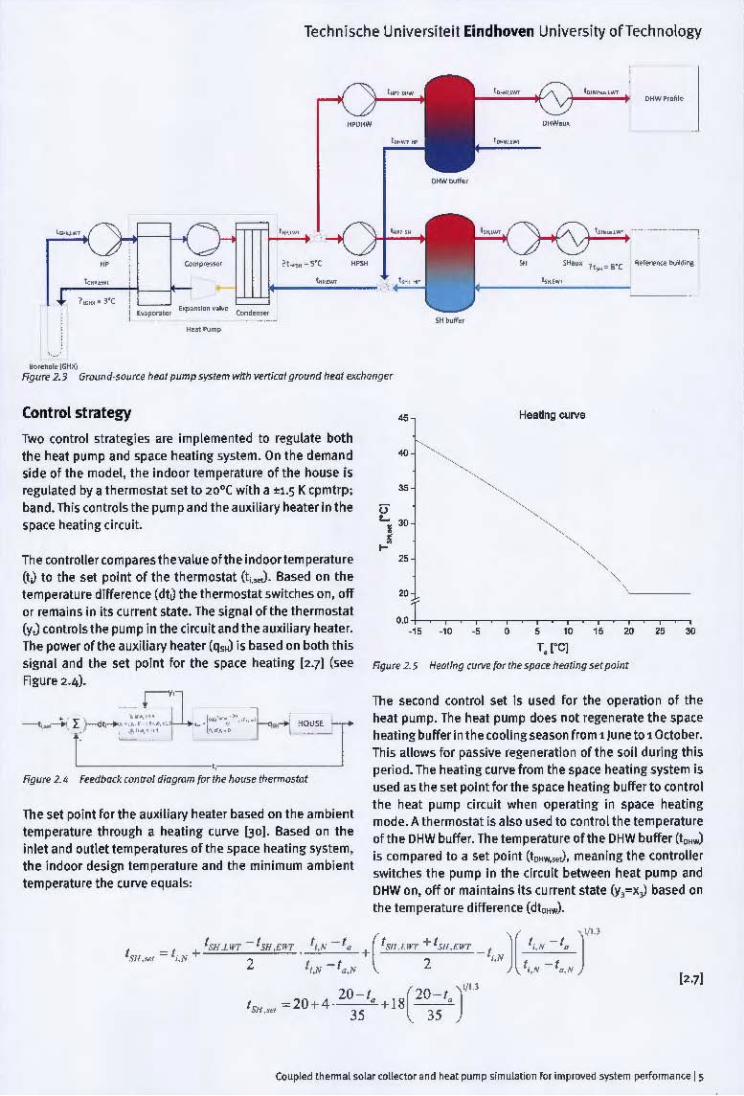
"---","ur< 1.> G""", O-' O""" /l.." pump>Y""m w1fIl ","ai gro<Jnd lI. o! _"9<'
Controistrategy
Two (ontrol .trategie. are implemented to regulate both the heat pump and space heating system. On the demand side 01 th e madel, the indoor temperature of the house Is regulated by I thermostat ,et to 20·( with a ~l.S K cpmtrp; band. Thi~ (ontrols the pum p and the auxiliary heater In the spa(e heating (["uil.
The controller compares thevalue olthe indoortem perature (t~ to the set point of the thermostat (t,...). Based on th~ temperatur~ dIfference (dtJ th e thermostat switches on, off or remains in its curr~nt state. The signal of the thermostat (yJ controls ttH. pump In the (I"uit and the auxiliary heate r. The power of the auxiliary heater (q..J is ba5ed on both this signal and ttH. set poInt lor the ~pa(e heating [2.7] (see Figur~ 2.4].
1'1 ~ I'-... -----.,~.; ;'" u..~ r··, " .. L - ""''' T 1' --....!."'·, I ~",' ~l .. _ _
NfI'i" 1_' f .. <iNd ''''' ~o/ ~iafl'Ml foe II>< h"",. ti>c'rmo,tot
The set point lor th e auxiliary heater based on th~ amt>i~nt temperature through a heating c~rve 130]. Based on the inlet and outlet temperatures of the space heating syst~m, the indoor design temfH'rature and the minimum ambient temperature the curve equals:
"
• o,J , , , , , " • , , , • " • • •
',r<01 Fig"" 2_S ~ ... ~ (ltfW foe ,I>< >poe< h",Un g _f'lJ;'"
Th e s~cond control set 15 used lor the operation 01 the n..at pump. Th e heat pump does not regenerate th e space heating buffer In the cooling season from 1 June to 1 October. This allows lor pa5siv~ regeneration of the soil duMng this period, Th e heating Curv~ from the space heating ~y~tem is used as the ,~t point for th~ space heating buffer to (ontrol the heat pump circuit when op~ratlng in space h~ating
mode. A thermostat is also used to control the temperature 01 th~ DHW buffer. Th~ temp~rature ollhe DHW buffer (t,.,..) is compared to a set point (t_,.,), m~anlng the controlle r switche5 the pump In th~ circuit betw~n heat pump and OHW on, off or maintains Its cu rr~nt state (y, -x,J based on the temperature difl~renc~ (dt"",,).
]l J"' /. -/
/ "~ ' I.~ /. /
',.' " ~
/ = 20 + 4 -20 -/. +18[20-(0 )"
>It,"" 35 35

Technische Universiteit Eindhoven University of Technology
Element Component Remarb
H~at pump Slngl~ Stag~ Water·Water
TYPE927 Normalized performance data Heat Pump
Borehole Standard U·Tube Venical
TYPE557! Ground Heat Exchanger
Three w<lo/ valves flow Divener TYPE11f
in heat pump-buffers dr<.:uit Tee·Piece TYPl:l1h
Pumps Variable Speed Pump TYPE110 in heat pump-buff!.',.; circuit
Auxiliary heate,.; Au"mary Heater TVPE6 Constant h~at output Auxiliary Heat (Fluid) TYPE659 PToportional heat output
Th ermostat Heating ModeAquastat TVPh-AquaslatH HY5teresis band of tt.5K (SH) 8. ·2.5/ +SK (DHW)
Buffe,.; Venical Cylindrical Storage
TYPE53'1-NoH)( Supply inlet/outlet, Top/tlottom
TankwithoutH)( [}emand inlet/outlet, Bottom/top
In the case thai both buffe,.; require regeneration, the DHW buffer has priority O'I'er the space healing buffer. The controller for space heating compares the temperature of the buffer (t..,) with the set point (I ... ,..). Based on the temperature difference, the thermostat (dt..,) produces an on/off signaL This value is then multiplied with the inverse value of the DHW thermostat (x,) and the cooling season indicator (IJ. This Is to ensure the space heating buffer Is
not re~nerated when a concurrent energy demand from the DHW buffer exists or during the cooling season. An on/off Signal (yJ is produced for the pump In the circuit between heat pump and space heating buffer (see Figure 2.6).
• -'. ~ . .... 'u _ " . __ I .'_t'"""""" .~"-"."'" T L " .'"
• 1'"-''' -l~' " ..... , ....... ,., - . Ngu" 1. 6 _"",0 <CWO! diogmm !« II>< _",Ii«! of /I>< I><ot """'I>
2.3.2 Para llel S(·GSHP system
The GSHP sY"tem is exp.anded by addition of a th...-mal sola' collector in parallel operation with the heat pump (Figure 2.g). Two collector panels of 2.26 m' are attached on the south facing roof of the 'efelence building, having the same slope as the roof (45.3''). The collector model is based on performance data of a solar collector flom t~ e SRCC database [}l]. The mass flow for the sotar <oIlector circuit Is the reference YlIlue of 250.92 kg/h. This circuit is conn ected to the same buffers as the heat pump system.
Controt strategy
The control strategy of the parallel SC·GSHP system for the demand lIde and heat pump circuit is Ihe same as
presented In §2.3.1. The controller for the pumps in the solar collector circuits works In a similar fashion to Ihose in the heat pump circuit. where the DHW buffer regeneration
takes precedence over the regeneration of the space heating buffer. The outlet temperature of the DHW buffer
to the solar collector (t", .. ,,) 15 compared to the outlet temperature of the solar collector (I",..,.J as shown In Flgure
2.8.
61 (oupl«l 'flo .... l.o'"' (011«"" .,,<l h .. , ~p <lm .... 'ion IDr rmprov«l '\'51_ perform.Jn<.
Technfsche Universlteit Eindhoven University of Technology
--.. -
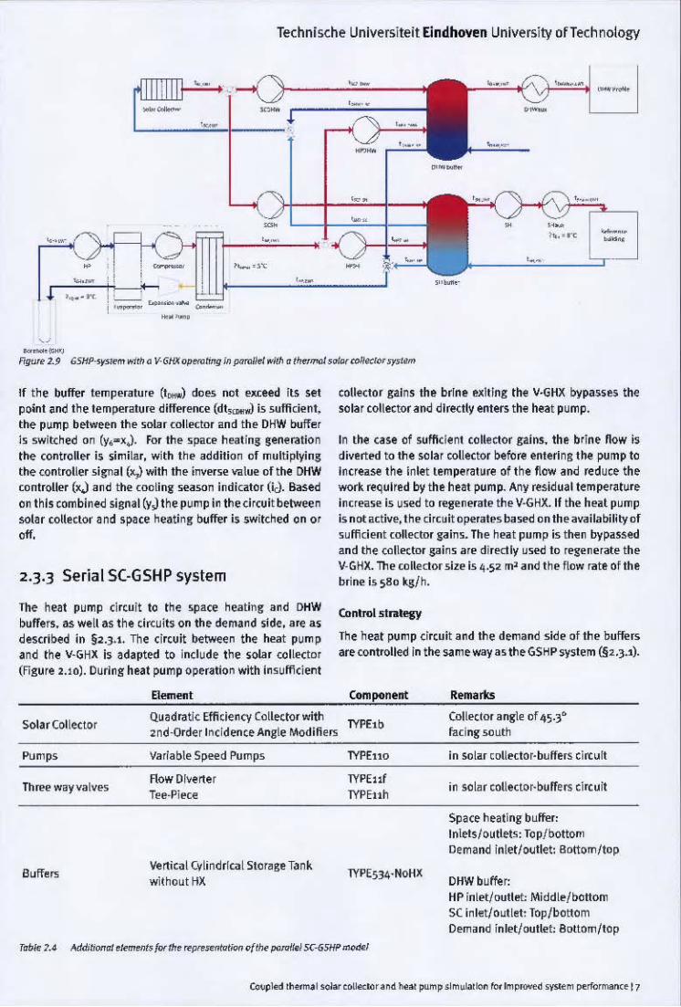
---fig"" 2.9 G5HP-,Y5_ wi'" 0 V_GI« ~ting in p.miII.1 "'t~ "t"'moI , ,,,,,toJl«tcr ..,.,,'"
If the buffer temperature (t_ ) do es not exceed its set point and the temperature difference (dt~ is sufficient. the pump between th e solar coll"dor and the DHW t>uff~ r
is switcned on (y. -xJ. For the space heating sene ration the controller is ~imilar, with the addition of multiplying the controller signal (x,) with the inverse value of the DHW controller (x.) and the cooling season indicator (iJ. Based on this combined signal (yJ the pump in the circuit between sol~r collector ~nd sp~ce neatin!!" buffer is switched on or off.
2.3.3 Serial SC-GSHP system
The he~t pump circuit to tn e .-.pace nealing and DHW buffers. as well as the cir<:uits on th e demand side , are as described in §2.3.1. The circuit between the heat pump Ind the Y·GHX is ~dapted to include the ~olar collector (Figure 2.10). During heat pump operation with insufficient
Solar Collector
Pumps
Th ..... way valves
Element
Qu~dratic Efficiency Collector with 2nd-Order Incidence Angle Modifiers
Variable Spee d Pumps
Row DI~etter Tee·PT~e
Vertical Cylindrical Stor. ge Tank
witnout HX
collector gains the brine e~ltlng the V·GHX bypasses the
solar collector and directly enters the heat pump.
In the case of sufficient collector gains. the brine now is diverted to the solar collector before entering the pump to
Incruse the inlet temper8ture of the flow and reduce th e work required by the he~t ~mp. Any residual temperature increase is used to regenerate the Y·GHX. If the heal pump is not active, tne circuit operates based on the availabmly of sufficient collector gains. The neat pump is then bypassed and tne collo>etor gains are directly used to regenerate th e Y-GHX. The collector size is 4.52 m' and the flow rate of the brine is 580 kg/no
Conlml5tnlegy
Tne heat pump circuit and the demand side of the buffers are controUed in the same way as th e GSHP system (§2.3.')'
Component
TYPElb
TYPEno
TYPEl1f
TYPEnh
Remarks
Collector angle of 45.3· facing soutn
in solar ",llector·buffers circuit
in sol" r collector· buffers circuit
Space heating buffer: Inlets/outlets: Top/bottom Demand inlet/outlet: Bottom/top
DHW buffer: HP inlet/oullet: Middle/bottom S( inlet/oull. t: Top/bottom Demond inlet/oullet: Bottom/top
Technische Universiteit Eindhoven University of Technology
--,.
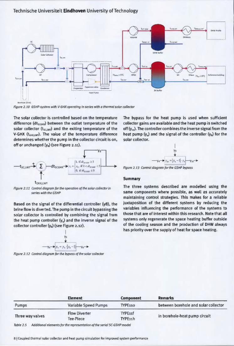
.---figu~ 2.10 GSIf~ .. tIl V-GI« ~~ .. " fin .. fIo ~ ' .... fIMi.oIa, wI_
Th~ solar collector is controll~d based on th~ temperature difference (dt~ between the outlet tem perature of th e ~oIa r collector (t~ and the ""iting temperature of t he V_GHll (t...:u.J. The value of the temperature differente determines wh et her the pump in th e collector circuit is on, off or unchanged (y.) (see Figure ~.1l).
-t><'L.,,-:t..- I ~t.o •• o'-" ·' - -'I. ;ro < .. .,..,,+.L_> ~ ['.;{"~d
1. .. ~" __ so
t""""WI fig"" ]. J J (;on/ro/ <hag""" for !II< oprrutioo 0( ~ """' ro/Iodw ill
•• _ .. lIlHh. GSH~
Ba5ed On the sisnal of th e differential mntroller (yB). the brine flow is diverted. The i>Ump in the circuit bypassing the solar collector is controlled by combining the ~i",al from the heat pump controller (yJ and th e inve"e s ignal of the colledor controller (y.) (see Figure 2.12).
-----....--f. -T. '!y,
ElI!menl
Pumps Villiable Speed Pumps
Threewayvatves now Oive rter TH-Pi e<:e
The bypass mr the heat pump is ~sed wh en sufficient collecto r gains are ~va;lable and the hut i>Ump is switched off (Y"). ~ controller combines the inverse Signal from the heat pump (yJ and th e 5ilfn~1 of the controller (y.) for the solar collector.
,. • •
-----....- '\, - \0'. - ~. >~.,--,>-ngu ... ,. JJ CQnfroI di<l9ram "", .... GSHi' /lfP<=
Summary
The t hree systems described are mod elled using th e same components where possible. as well as accurately maintaining control s trategies. This makes for a reliable juxtaposition of the different systems by reducing the variables influencing the performance of the systems to those tnat are of Interest withi n this research. Note that aU systems only regenerate the space heating ooffer o~tslde of the cooling seaSOn and the production of DHW always has priority over th e supp ly of heat for space heating.
Component Remarks
TYPE110 betwt.en bo~hote and solar coliector
TYPE11f In bo~hole·h e ~t pump circuit TYPEnh

Technische Universiteit Eindhoven University of Technology
3 Results
Simulations of the three systems were conducted for a ~iod of three y~rs, with tim e steps of 6 minutes. The results from the third year of simulation were used [161 to compare th e performance of the systems, so to remove any run·up effects.
The system~ are assessed in three ways. Firstly, the COP provides insight on th e perform ance of the heat pump u~ ed. Secondly, the sea~on performance factor (SPF) is used to assess the performance of the system as a whote. Lastly, the efficiency ratio (~ .. ) determines the energetic efficiency of the different systems.
In addition to these assessments, we reviewed the performance of the solar collector In terms of usability and collector gains. For the analysis of the ooreho\e, 25 year simulations were used to determine th e long term effects ollhe addition of a ""lar collector on the depletion of the ground heat exchanger.
3.1 Coefficient of performance
The COP is the measurement In which th e performllnce 01 (compression) h~t pumps is represented. It is the relation i:>etween the enerS)' delive red by the heat pump and the e lectrical energy added:
[). II
The COP is calculated from the monthly e~rgy sums of ele<:trical energy and energy extracted from the vertical ground heat exchanger. This provides an overview of the annual Jl" rlormanct of the h~t pump, shown in Figure 3.1.
'.' l' =:.'"'1 --'.' • • • • 0
'.' • • • • • • • 00
" & " 0
• • • • " • • • • " , .• 1,
., ~# ., .,v., ..,t # # 0/' d> ~ <jf'
'.'
" • • • I
• • 0
~i ... • • • • • • • • • •
u
..,1 , "~.:I-!''; ''''# ,J''''rfr''<I"
-" FI!lUT< J.1 Hoot pump WPf<y .poco /o"" i"9
We (an see that for all systems. the COP drops signifiClintly in the summer Oune-September), during which energy is only supplied to th e DHW buffer, requiring higher lwerage temJl"ratures and therefore lowering th e COP.
The parallel S(·GSHP has the lowest COP of the compared systems on lin annual basis. This is due to the simultaneous OJl"ration ofthe solar collector and heat pump. resulting In higher entering water temJl"ratures to the heat pump on the load side if I>oth circuits are operational. SInce the heat pump is controlled indeJl"ndently lrom the solar COllector. it win supply energy to the b-uffer ~en when the collector gains are sufficient for regeneration of the buffer. This effect is therefore most pronounced during the summer. wh en collector gains and temperatures incr~se.
Th e COP of the serial SC-GSHP system is increased compa~d to that of the GSHP system. As collector tains increase in the summer, the inlet temperature of the heat pump on the source side is increased, requiring less
'." '.71
• - ,~ • • • • I • • • 0 • •
& 0 ..
0
• .01 ,
• • • • • • • •
· ~ ._._--_ ... _ ..
• • 0 • • 0
.,~.,,t'; -I" ~-!,.j><I"~<I" -FfgvroJ.J _ _ COP{o<DHW
Technische Universitelt Eindhoven University of Technology
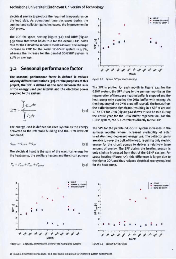
e lectrlCilI enerJY to produce the requi red temperatures on the load side. 145 operationa l time dK rUSH durin, the SUmm..r and rolle<to r ,alns Incruses. the ImprlNemen t In COP !'0W'i.
The COP for spl(e IIeaIln, (flrure loll lno$ DHW (Fl, ure J .Y show tt..! what hol4s lru. for Ihe _all COP, holds true for Ihe COP of tile sepaqte modes IS well. The "",rawe incruse In COP for the _~I SC-GSHP syslem Is ]on.. whe.NS the In"Nsf for the pilrdel 5(·GSHP system Is L9"JIo on ~rqt.
3.2 Seasonal performance factor
The _I pe.for""'II<e fktor 1$ dtftMd hi YllrIooIs ways loy diffffent Imtlt.UoflS [ll). ror th' purJ>OH5 of tills p"'ied.. the SPf II detlroed as tilt rlWlo bt~ tM ... rn of the enerlY uHd pel" IftlffWI MId the tlltClrleM power ... pptied to the IYJ-!_:
The eneo", used Is dinned for each system IS the energy deH ... red 10 the re~rence bulld ln, .nd the DHW draw·off combi ned:
The eledrkal lnpulls the sum of the e lKlrlul , neogy lor the heat pump, the .uxiij. ry hutffs i nd the circuit pumps:
,,..,
• , •
• • • • • • • ". • '. • • • • • • , • • ,
• • • • • ,.-# " , -I""<I~"<I' _.
F",,,,,"J.~ .s.._I'b~_~' {«/WD{IN '*>I_P'_
,
• •
~.
• ~ . , •
•
• • • • • • • • •
• • •
"""';"';"~-I""<#"'II -f/gu«J. s Sr>t-5ff1o<~-..g
The SPf is plotted lor each month In FI,ure 3._. For the GSHP s'(5otern, the SPf d,o~ in the SUmmff months IS the re,~rati<ln of the space heatln, buffer Is Slopped and the heat pump only supplies t he OHW buffer with energy. AS the fTequerI(:Y of the OHW draw·offls smal!, the losses lrom th e buffer become significant, resultins in iI SPf of around 1. The SPF 10' OHW (figure 3.6) shows thi s to be true durfng th e enlire year for Ihe DHW buffer resene,.tion . For Th e GSHP symm. Ihe SPf correlates directly to the COP.
The SPf for I~ parallel SC·GSHP system IncrelSH In the summer months w~re increased n~iLabllity of sollr irradlalion and decreased eMrgy use. The co llector l.Jns I re ablt 10 COYer t he bulk ofl~ leld. requ1rins only ele<trl c eneogy for the tircult pumps to del""" I relilive ly Lalle aroount at eneogy. The SPf durt.nl the hNt lns selson Is only sUshl1y inClflSed lrom thlt at the GSHP system. for ~ce headfl! (Filllre].5). this dm.,ence Is Llrsef due 10
the hisher COP. ind thus ~UCfS elKlriCl1 enefBY required lor Ihe hN I pump.
• [ : r:~ , •
• • • • • ~
I' • • , • • • • • • • • • • • • • • • •
• ,<!'# .... , -I"""<#"#"II _.
Rgw J.6 $pl..", 5ff lor VIIW

Technische Universiteit Eindhoven University ofTechnology
For the seroal SC-GSHP system, the SPF is only increased from that of th~ GSHP system due to th e higher inlet temperatures of the heat pump on the source side. This improves the SPF for spa<:~ heating, oot virtually do es not changetheSPFforthe supplyofDHW. Compared to the GSHP system, the annual SPF for the parallel SC·GSHP syst~m Is increased by 8]%. For tht paralle l SC-GSHP system this increase is only 4"". As the solar collector operates in ser;"s with the heat pump, electrical energy to the heat pump is a lways required to supply energy to the buffe rs, contrary to the paralle l SC·GSHP system where the solar collector can supply energy to the bul'!..rs directly. This explains th e differen ce in SPF increase between tm. systems.
3.3 Energy efficiency ratio
Neither the calculation of the SPF and COP provide information on the ratio between th e energy available from collector and ground heat exchanger, or the amount of energy used by th e system. To incorporate the collector gains and the energy used for regeneration olthe soK and compare th e systems, an en .... gy effici ency ratio is used. For this project it Is defined as:
11 - QF + QII' + Qw.., <If - {1I1X + Q. ... + Q_ + Q ..... [3.51
For the GSHP system, both th e solar irradiation and the collector gains are irrelevant . The ratio between energy used and ene rgy supplied (Figure 3.7) is only Infiuenced by the losses from th e energy buff .... s . For the space heating buffer, the draw-<lff is more frequMt than for the DHW ooffer, therefore reducing tt... percentage of energy being lost. During summer, the space heating buffer is not regenerated, which increa ... s tt... percentile loss from the buffers.
• - ~~. ,. .==1 • • • • • • • ,.
• • , • I • • I • • • •
" • ;;: , • • • •
• "
• • • • 0
~ " .. ~ .; " • .- " d' .. '" ~
Fl!luro 3.7 CM'W effici.n<y ""';" of ,~. _ , P'I"'P , )'>,,,.,
The energy efficiency ratio of the parallel S( ·GSHP system is influenced by the amount of collector gains used in comparison to the available solar Irradiation. Due to inlet temperatures for the solar collector being often higher than the ambient temperature, the solar irradiation level has to be high enough to compensate lor th e conv~ctive losses due to the temperature difference between fluid and am ble nt air. During the winter this in fluence is small when the solar irradiation levels are tower. In summer when the ratio drops, wilen solar Irradiation ~Is are highe r and energy demand is at its lowest.
Tm. se nal S(·GSHP system's energy efficiency ratio increllSes in summer, as collector gains are used lor regeneration, during which tim ~ the system makes more us, of the available so lar irradiation. Oue to lower entering t~mperatures to the collector, the dil'!..rence between ambient temperature and collector temperature adds to th e available solar irradiatio n and raising the energy efficiency ratio over 1000/.. The average diffe rence of the ratio compared to the GSHP system is '20"Ao and + 2r'io for the parallel lind the se rial SC-GSHP systems, respectively.
3.4 Solar collector performance
As mentioned above, tne use of solar irradiation drops during the summer for the parallel SC-6SHP system and rises for the serial S(·GSHP system. We also stated that the convective heat transfer Irom between ambient air has a negatlve influence on th e performance of the solar collector for the parallel SC·GSHP system and a positive one for th~ serial SC- GSHP system. Figu re 3.8 corroborates these lindings.
• -=~ , SerioI SC-IOSI1 "
" • 1.153 " · 40!1~
. ~ •
[ . [ . ! I •
I' ! ' •
o __ . , , . I • ,.. I __ "WI _ 1._ ,[kW)
fi9i.ir< J.~ n.. dislo-i!>Wo<o a{«OII<""'J1Oin> for di(frr_,%r j",,,ja tioro 1...-.1>
Teci"1I1ische Universiteit Eindhoven University ofTechnology
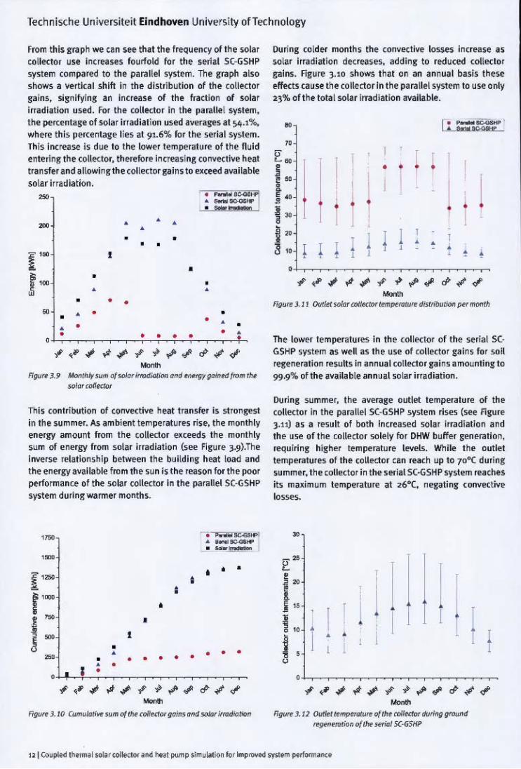
From this graph we can see that the lrequency olthe sola' co llector use Increases lourfold for the serial SC-GSHP system compa'ed to the parallel system. The graph a lso shows a vertical shift In the distrib ution of the collector sains. Signifying an Increase of the lracUon of solar irradiation used . For the collector In the parallel system, the per<;entage of solar Irradiation used averases at 5-(p .'%' wh ere this percentase tiu at 91.6% for the serial system. This increase is due to the towe, temperature 01 the fluid enteri ng the colledor, th erefore increasing convf'ttive heat tran sler and allowingthe collede>r gains to exceed avai lable solar irradiation.
=
I r ..
I,· •
• •
• =:=1 • • • • • • • • • •
• • • • • •
• • • • • • • • • • • • • • • • •
" c; ~." " -./'''' <f"<f -MMIfII\' .... 0( I<>k:r im>diotiM <HId "'''w gofnrd {rom ", •
."jo' «J/If<kx
This contribution 01 convective heat transler is slmnsest in the summer. A.s ambient temperatures rise, the monthly energy amwnt lrom the co lledor exceeds the monthly sum of energy from solar irrad iation (5"" figure 3.9).The i~rse relationshi p between Ihe building heat load and the energy available lrom th e sun is the reason lor the poor performance 01 the solar collf'ttor in t he parallel SC·GSHP system during wa rmer months.
• • •
•
• •
• •••• • •
• • • •
• • • • I • • '4-+--'-~~~~~~~~ ., ~, ., .v.,. ,I" ~ ~ ., cI" .,; " -FiIl'H' J .10 ( .... "10';,." ,"m of"'<1 co/IWor goin, orKI ~ imI".,_
During colder months the convf'tti~ losses increase as so lar irradiation df'treases, add ing to reduced tolletto, gains. Figure l.lO shows that on an annual basis these effects cause the collector In the Il"rallel system to use only 2l% oflhe tota l solar Irradiation available.
0 1": -~ _K9ft-
" " I
I
I ! I co
I i: • • ,
I i I I I I ~
I" I J • i , ,
I: I I I , 1
I I • • ! ! , , , , , , • • • "~:I~';""'~~.!'cP";" -'--" l.l l Outl" """' a>ll«flH rrm~"'~ diltri,,"_ (Hr mooth
Th e lower temperatures in th ~ (0I1l'(tor 01 the serial SC· GSHP ~ystem as ~ll as the use 01 collector sain, lor soil 'egeneration ,~sult, in ~nn ual collKlOr gains amountins to 99-9% 01 th e available annual solar irradiation .
During summe r, the average outlet temperature of the coilector in the parallel SC"(;SHP system rises (see fi gure l.U) as a result 01 both incrused sola ' irradi ation and th ~ use oltne collector solely fo, DHW buff" r generation, .... Quiring hisher tem perature levels. While the outlet temperatures 01 th e collKior Can reach up to 70°C during ~umm~r, the (0I1e(tor in the serial SC·GSHP sy.tem .... aches its maximum te mperatu ,e at 26"(, negating tonvKtiv~
losses.
"
I I I • •
•
I I i
" ,.I'-:I.v;"",~"",.!'cI""; " -F>gOM 3.11 !NtI<I t<~ of/h. a>llottor <1url~ gn>ur>d ffJI""<ff1fion 0( tlr< smal SC·GS/lP

Technlsche Universite it Eindhoven University of Technology
3.5 Ground heat exchanger
Th' ral' of depletion oIlhe vertical "ound hUI eJ.(hlnlfl dl'lermi~ Ihe ope<iltlonilllifuP4n. When the heatln, and loolin, loath iI.' IInbilla need, Ih e soil Itmp tf.tturt dtylatts is ope.alionill lime inCfHHS. The SYSltmS tum;n.ecj In this projecl $\I~ plyonlyenern fo, spKl hNII"I Ind OHW. II coolln,kNd. Iqul.1rty u$ed!Of lhe 'fSentfation 01 Iht !.(Iufte, ls noI present. for theGSHP sYSlem and the ~'aUe! SC-GSHP sys.Iem this mHns thlt active It,_,allon Is l1l)I
po!>Sibie. The addition 01 thl!.Oll. collt<:lOI In tht ~.alltl
!iy!>\em dotS redUCI 1f11 amount 01 tnt"" elIlracled horn tile V-6HX (Rlllre ).1]). bill o/fIf$ no pos!olblllly to
~ne"'le the V·GHJl
- • • •
i- • •
1,1 =~== ~ .... _ ............ u""' ... "" .... _ · -I-
• • , • • • • • • •
• • • • , •
I n th t St rillS ( -GSH P system Ih f collector UI n '",noerate Ih e V·6HX both dlre<lty ,nd th,oulh hl,he. retu.n tempeuture~ to the soi l. Asure ] .• ] sl"low'$ Ihll is lempeqtu res and ~. Irradiation l",reiSf in ItIt SlImmer, the ext",ctlon 01 1'!101"fD is rtduced ilnd O\IIside the hfillln, !.filson, mew, enOl"fD is $\Ipplied to the v·6HX tMn ewaded. thE"felewe Iqeneqti"l ttlt soufte. By dol .... so. lhe a nnUill edf<Klion of entlD Is rtduced by" )'8"4 compared 10 ItIt _"" elIlraned by the GSHP system (Sff ",Ult ).1.). This Is iI sIJr. fokIlnCfNs.e COmPlIed to ItIt.:fJ'o reduction achieved by the pafililel SC-GSHP system.
- r-=~ ,
! - - - - '* ".~
f - ~" -1 --
~ w .,-
-
0-- Ii"",. tile aWl'ilge temperawre oflhe V-GHX oqrles due 10 this ""'ID """fiCtion a nd active Of passive 1'1_lltlon (fi,lUe 3 .• s). OuTing the hllllni Hlson. the temperature 'HrnB It. IawUI point around Ma rch. After this point the re-ducing hNI Load ~nd increasing am bient temperature cau~~ pa.s.iv~ r~gen~ratlon of the V·GHlI, this ralsH the soil temper.!tur~ 10 ilS hi",eSl valu, around September \)efore Ih~ h~aling season SlallS again . The Influence of active re-ge"".alion is pronoufl(ed, showing sl!nl"Clnlly higher teml"',aturB tor the ~flal SC·GSHP system than for the other sy51~m5. Where the tempelatures 101 this system drop O.I·C IIW'f the Ihild yell of ope(alloo. the soil tempe",ture tor the GS HP and p;1IlIlI'l SC·65HP system drop 0.]"( Ind 0.25·C, lt~i""ly.
for Ion,·term operation lime this melns Ihll t he Ihermll e"ern 01 the soil wi. ~"''''te slower tha n 101 Ihe palallel and G$tiP $y5tem. o.er I simulilion petlod 0115 yeals. Ihe ttmptfitUIt at the e nd 01 eiKh yeal is IKOlded and planed ill "SUit ].16. The _ase tempeqtult deays 1~"'S!olvoeIy. resulting in a 2 .1"( tempe<llult decay foI Ihe p;1Ila llel S( -GSHP sr;t ....... dill ... i,,! on.., sHilhl llOm that of the GSHP SY5ttm (l.l"C), whtrNS the lemperailire de<1'f of the serial SC '('SHP SJ'i'lem is on.., hall with 1.1"(.
• =-1 --, ,
~--.--:---. ........... ~-
~-----
, , , ,.,T!---,--~~--y, ---'"
• • '" " • n Y..sIYl
fig"", 1. J6 AootJoi,",""""""" <k«r{D(II1. g<rN;d

Technische Universiteit Eindhoven University ofTechnology
The performance indicators and results discu .. ed in tnis cha pter I>fovlde Insight into the Il"ITormance of the system ~s a whole, the performance of the main components, and
th e durability of th e system. Tile talXe below provides an overview of th e ~suk. presented in this chai>ter.
Performance indicator GSHP ParaILeISC·GSHP SerlaISC-GSHP
COP [-] )·4~ ).51 (102%) 3.57 (104%)
SPF[·] 2·35 4.39 (187%) 2.~4 (104%)
f\.o"H 0·79 0.63 (80%) 1.01 (127%)
S<>larfraction H '" 23.1% 994>'.
GKX ""'''i>' extraction [kWh1 1751 1526 (8;0%) 395 (23%)
Aooual tempHature decrease () .. year) ['"C] 0.; 0.25 (8)'11.) 0.1 (:33%)
long term te mpe rature drop ['(/25'11 " 2.1(92%) 1.1 t49%) _ .1.1 0-",,.,; .... 0( 1M p<rfi>r"","c< i<>dica<(X'S Ie< 1M <11",,,,,«1 /toOt pump ,)">1."",

Technische Universileil Eindhoven University of Technology
4 Discussion
from the result~ we conclude that the addition of a solar colllKtor has no significant influence on th e COP 01 th~ heat pump. This Is due to the natural shift between heat load and solar Irradiation. For the parallel S( ·GSHP system the increased COP is due to the reduced share of DHW in th~ energy supplied by tm. heat pump. The higher inlet temperatures to the heat pump muse the increas.e of COP in the serial SC ·GSHP system. As far as tH.ing a performance indicator for the SC·GSHP system, COP is not suited for this purpose.
The Sf'F prol'ldes a better insight in the performance of the system as a whole. The advantages 01 adding a solar collector to the parallel system become immediately evident. When the solar collector operates without the heat pump, the SPF is vastly Increased, since only the electrical energy for the circuit pump Is required to del;"'er relative high energy amounts to the load. The SPf of the serial 5(· GSHP, however, does not differ In a significant way from the SPF of the GSHP system.
The increase in COP, and therefore the reduction in e lectrical energy to the heat pump, Is the sole cause of the ~% increase in SPF. The energy from the solar collecto r used On)<jirectly to regenerate the source is not included as tm. SPF calculates th e ratio between enl"rgy deli""red to the load and the electrical energy required to do so. Using the SPf for comparison 01 th e systems gives a distorted view of the performance.
To incorporate the u'iability of solar irradiation, the enl"rgy efficiency ratio provides the best option amongst the performance indicators. By including the collector gains, the enl"rgy efficiency ratio provides th e tH.st picture of the relationship between useful energy and available energy inputs.
The GSHP system has a ratio of 0.79, meaning that 79"1. of tm. energy put into the system is uselully used; the remaining n 'l'O are various losses. The parallel SC·GSHP makes little use of the available solar irradiation, lowering th e ratio to 0.6]. Th e lower temperature levels in the solar collector of the serial SC·GSHP system Improve the ratio to 1.01.
The reference building used lor the purpose of this proj lKt is a simplified model of a dwelling; the influences of solar irradiation are oot taken into account. Thi. coold affect the Jnnua l heat load and therefore th e dimensions required for th e system. It may also cause a cooling load, requiring the heat pump to function as chiller In the summer. As this was not the focus of the project, the cooling 01 the house was not taken into account. However, it rais es the question what influence cooling the house during summer has 00 the peliormance of the system.
The solar collector used in the simulation consists of two panels with a mass flow equal to the testing rite. Due to time constraints and th e scope of th e project. no research was conducted as to the optimization of collector size and flow rate. The optimal values for this can differ for the pirall~1 and serial system, colouring the results. The buffers used are dimensioned to reduce on/off switching of tile heat pump, oot may require a diffe rent design approach to optimize their use for the buffering of collector gains.
Th e simulations of the paralle l and serial SC·GSI1P models are validated by adhering to design guidelines, is no experimental resuits were available for comparison. An experimental setup 01 both systems is required to prove beyond that the simulated results Me realistic. No anomalies in the peliormance of the systems were found during til e simulatioo of the systems, which leads uS to believe that results from experimental validation will be in til e same order of magnitude.

TKhnische Unlvl'~itl'it Eindhown University ofTe!hnolosv
5 Conclusion
ThrH tINI pump ~v~errt5 a re ~mul;lt!'d ind ccmp.frtd tB el.mine thett FtIform"ne,e as _U u the inlluence of Ihl addition of • $Olar collector In dlff.t!ftt po!>/ti<Mls 10 Ihe S't'5lem. The petfotm~lI(e ofthe p~raUellnd the serial S(GSHP system Is tomplred. usln! Ih. GSHP system as the rtltrenee syslem. Usln!" consequent heat load con$lnlfog 01 Sp;I'" """till! a nd DHIN, Ihe syilelllS are simullrted using fRNSYS. The ~lts lIre procesed ~nd Ihe perlorrnance IndlGllofScompared. Th e perfiI.",_,.,e Indicaton 1ft u~ to answ..r our reseal(h question:
• "How ~o I GSHP sy~~m. I pardel SC·GSHP SIfSIem. and a Stflal S( -(;SHP system compare In II""S of
enef'Sl"lic emcifnCY'
Compllred 10 the GSHP system. the p3rallel S(·GSHP has an Improved SPF, ,unutlnll' an ImprBlltmlnl to tile system. Howevef, it is on~ able to use JJ'lIo ollhe avaIllrble sol'" In.dlatlon, thus 1'101 ImpKlYlns the In"-Selic efficiency. In fact. its entflftJc efflclency IS only 8c'!l. ollhal oflhe reltfence system. For the sellal S(-GSHP 5y5l1m, Ihe collector gains Ire almosl equal to the solar irradlallon. BV using the colleclor to actlwly r,generalf lhe soR. . n implU'Vemenl oIls"llo is acllieYed In le rms 01 enerD effIcimcy. The act!vto tf:S_l3tlan ollhe soil n rn dl he< &.lIend Ille opeo-allO<llime at the I/-G HX '" aUow fOf $horte< or less boreholu; both effect5 <an translate into ecerooml c adv~ntages.
5.1 Future research As the ope"~lionallifetime olil/-GHX is u,ually set 10 2)
years [291. the addition of a solar collector In the circuit could ~rovlde an o~rtunlly 10 redlKe thl length of lhe
boreholes. depending O<Ith, loCll.r cdeclOr sin. Researcll should be condlK1ed to Irwesllgate Ihe r""tlon ~" toIlector pins lJId the RCiuired borel101e depth to su:.t..n 11 2) yelr Ufespln.
With in the fie ld 01 hybrid h~al ~mp SVSte ms, il clli Is mide /01 a syslo>mallc and compa,at lve anitlysis of diffel"eIIl po5~i"'" SVSIen11o. und .. different cond itions a nd for dlll .. ellt <Umoles In ]. We suggest therefore elttendlng Ihis reSl!ilrdr 10 ill(lude the system ClltKeriu defined by Herkel, Mlara ilnd Kal e",r 1151.
In ...unl ~,s the t ombl"l,.. 01 Fholovoltalc Ind Ihermll sola, colle<.rofS inlo f'V/T colledo~ has been I highly ' ...... arched lopic. This combillillion hn Shown 10 Improve the performance oflhe photollOltaic compone-nl by eflki tnl remova l of heal !>ylhe colledo.fluid, i,.tr~sl"g the therm al effi<iency of the colle<lOf ai well ~I. Usillllhe elect rical yield olltle ~/T collector I", the BPtfallon 01 !he hut pump S't'5ttm can further ifl(rtaSl! Ihe energtl ic effi<iency of the sy:stem. It is ~OO'Im.nd!'d lhal f>V!T colll'f:to~ art includ~d i,. further rHearch Inlo S(·GSHP svslems.

Technische Universileil Eindhoven University of Technology
Bibliography
1. lEA. Renewables in g-lobal energy supply. [Online] J,muary 2007. [Cited: 30 Ju"" 2011.] http://www.iea.ors/ pa pers/2 0061 ren ewa bI e _fact sh eel. JId f.
2. REN21. Renewables 2010 Global Status Report. [Online] September 2010. [Cited: 30 June 2011.] http://www.ren21. net/ Portals/97/documents/GSR/REN21_GSR_2010_fuIL revise d%20 Se pt2 01 O. j>d f.
3. Europun Environment Agency. Final energy wn5umption by sector in the EU·27. 1990-2007. [Online] [Cited: 30 June 2011.] http://www . ...,a.europa.eu/data· an d·m ap5/1lguresl d5 _ re50 tve u i d 12) U 2 PXFH12.
4. A review on sa/ar·assisted heat pump systems for domestk heating. Trinkt. C. ZOrne., W. and Hanby, V. Freiburg: Deutsche Ge5ell5chaft IUr Sonnenenersie. 2004. EuroSun 2004 Proceedings. Vol. '4· 3-"9809656'4'3.
5. Distributed dynamic modelling with experimental vo/idalion 0/1 a photlNOltoic solar·assisted heat pl,Jmp. Ii, I .. g IL 5, 5.1. : SAGE Publications, 2008. Proceedinss of the Institution of Mechanical Engineers, Part A: Journal of
F'uwer and Energy, Vol. 222, pp. 443'454. 0957·6509.
6. The heat pump and solar energy. Sporn, P. Ind Ambrose, E.R. Phoenix. A1 : Stanford Research Institute, 1956. Proceedings of the World Symposium on Applied Solar Energy. pp. '59'170.
7- Performance of a heat pump I,Jslng direct expansion solar collectors. Ito, S., Miura, N. and Wang, K. 3, 5.1. : Else\'ier Science Ltd •• 1999, Solar Energy, Vol. 65, pp, 189' 196.0038·092X.
8. Performance characteristics of integral type solar· asslstt<i heat pump. Hung, B.J. Ind Chynj!'. J.P. 6, 5.1. : Else\'ier Science Ltd. 2001. Solar Energy. Vol. 71. pp. 403' 414.0038·0S!2X.
9. SoIar·assisted heat pump and energy storage for r~sidential heating. t;omlkll, 0., Ka)'gUSU2, K. nd Ayhln, T. 5. s.l., Pergamon Press Ltd .• '993, Solar Ener!y. Vol. 51, pp. 357'366. 0038·092X.
10. A comparison of the performance of a di~ctexpanslon solar assisted heat pump wOIt./ng with R22 and a mixture of R4a;!C-liql,Jefied p~traleum gas. Mohlnraj, M., JIY8raJ, S. and Munoleedhal1ln, C. 7. 5.1.: SAGE PublTcations, 2009, Proceedings 01 the Institution of Mechanical Engineers, Part A: Journal of Power and Energy, Vol. 223. pp. 821·833.
0957·6509.
11. Simulation of a photovoltalc/thermal heat pump system ""ving a modified rollector/evapamtor. Xu, G .• et al. 11, 5.1. : Elsevier Ltd, 2009. Sola, Energy, Vol. 83. 003B·092X.
'2. Experimental inVl!'stigatian and a dynamic siml,Jlation at th e solar·assisted energY'storaged heat pump system. Cam~kll, 0., et al. 2, 5.1.: Pe rgamon Press Ltd •• 1993, Solar Energy. Vol, 51, PP.147·158. 0038,0')2X.
'3. Solar heat pumpsystems fordomestk hetwoter. Aye. L.. Charters. W.W.S. and Chalchana. C. 3. s.l., Elsevier Sdern:e Ltd. 2002. Solar En~gy, Vol. 73. pp.I69·'75. 0038·0S!2X.
'4. Assessment of the viability of hybrid geothermal heat pump systems with so/or th ~rmal collectors. Chiasson. A.D. and Yazuzturk, C Kan5as City, American SOCiety 01 Heating-. Refrig-erating and Air·Condltioning- Eng-Ineers. 2003. ASHRAE Transactions. Vol. '09(2). pp. 487'500.
15. Herkel, 5., Mill'l, M. and Kag-erer, F. Systemintegmtion Solar + Wiirmepl,Jmpe. [Presentation] Bozen. Italy : Fraunholer In5titut liir Solare Energies)'5teme ISE. 30 April 2010.
,6. Combination of solar collectors and ground,sol,Jrce heat pump for small buildings. Kjell5on, E., Hell5trllm, G. and Perers, 8. Orlando. FL : Ame rican Solar En ergy Society, 2005, Proceedinss of th e 2005 Solar World Congress. 0·B9553·ln· l •
'7- Unglazed color collectors in heat pump systems: measurement siml,Jlalion and dimensioning. Bertram, E., ft ~L lisbon: Inte rnational Solar Energy Society, 2008. EuroSun 2008 Proceedings. pp. 235,1'7,
l8. Performance analysis ota solar·assisted grOl,Jnd·source heatpump system forgrrtnhOl,Jse heating: on experimental study. Ozgener, O. and Hepbasll, A. 8, s.L : Elsevi er Ltd, 2005. Building and Environment. Vol. 40. pp. '040"050. 0360'1323.
19. DGMR Bouw. Reftrentit:Woningen nleuwbouw. Sittard : SenterNovem. 2006. p. 27. 2KPWB0620.
zoo METIOTEST. Meteonorm . Global Solar Radiation Database· METEONORM. [OnlTn e] METEOTEST. [Cited: 7 March 2011.] http://www.meteonorm.com/pages/en/ meteonorm.php.
2 •. 1550. ISSO·publicotie 80 • Handboek inwgraal antwerpen von coUeelieve instaUoties met wormtepampen in de woningbouw. Rotterdam: ISSO, 2007. 97B'90'5044' 134.6.

Technische Universiteit Eindhoven University of Technology
22. Mini5try of Agriculture of the Czech Republic. Report on WlJt~ monogement in the Ctech Republk in 20<>9. Department of S!<Ite Administration of Water Management ind River Basins, Ministry of Agrku!ture of the Czeth Republic. Prague : Ministry of Agriculture of the Czech
Republic . 20l0. 978.80'708""926'2.
.13.0ECD Soc!11 Policy DMston. SFl.l Famity size and composition. OECO Family database. [Online] 1 !uly 2010. {Cited: 12 May >Oll.] http://www.Of!cd.o'!:r/
dataoecd /51/2/4 22938 ;>6.xls.
2~. DeOreo, W.B. lind ~yer, P.W. The end usesofhotwater in single {omily homes {rom /lowtmet' onolysis. Bou lder, CO : Aquacraft, tnc., 2001.
25. Jordan, U. and Yalen, K. Rtollstlc domesllc hot· watt( profiles In dl{ftrent time scoles. Fachberekh Physik,
Philipps·Universit'!t Marb urs. Marburg : lEA SHC Task 26: Solar Combisystems, 2001.
26.1S5O. ISSO'publicotie n . Ontwerpen ",n IndMdue/e en Idein elektrische warmtepompsystemen voorwonlngen. Rotterdam: tSSO, 2006. 9]11'90-5044'126'1.
27. EN '45" Air conditioners, liquid chilling packages and heat pumps wit/r electrirnlly driven compreS5= {or space heating und cooling. TedmiGl I Committee CEN/ TC"3 ~Heat pumps and air conditioning units", European Committee for Standardization. Brussels : CEN, 2007. EN '45":2007.
2B.Ameritlln Sodety of Hutins-, Refris-e.-inl ~nd Air· Conditionins- Ens-in_s. Intemotionol Wtoffrer {or Energy Colculotions (IWEC)CO·ROM. JCD·ROMI 5.1.: ASHRAE, 2001. 19318621;>6.
29.1550. ISSQ·pub/icotie 73 . Ontwerp /!II uitvoering ",n verticole bodemwormtewisseloors. Rotterdam: ISSO, >005.
978"110'504""12 8'5.
]0. -. ISSO·pubUrntit 38 • Hondbotk warmtepompen. Rotterdam: 1550, 19')6. 9°'5044'052 '5.
] •. Solar Ib.tin, & Certification CDrporation. SRCC Search Collector Retard Oetail. So/ur Rating & Certifkotion COrpDrotion . Home Poge. [Online] Apr~ '9, 2008. [Cited:
May 5, 2011.) http://securedb.fsec.ud.edu/srcc/coIL detail?S1Ccid-,0o8007A. 200S007A.
32. Wemhtiner, C. and Aflel, lb. Seasonal perfbrmam~t calculation {or residential heat pumps with combined space heoting and hot water production (FH88 Method). Institut~ of Energy, fachhocn sdmle Nordwesl5cnwe iz. Muttenz : University of Appli~ Sciences Basel, >003.
33. Solor ond heat pump s)'5"tems; 0 new lEA SHe Task 44 & HPP Annex ond analysis of Wo'erol combinotlons {or 0 low energy house. Hadom, !ean-Chrbtophe. Graz, Austnll : ISES, 2010. EuroSun 2010 Conference.
34. The thermal and electrical ~Ud of a P\I·thermal col/ecmr. landag, H.A., et It. 2. s.1.: Elsevier Science Ltd. >00>, Solar Energy, Vo l. 72. pp. 11]'128. 00]8-o')2X.
35. Nemecek, Ian Ind Josef, Kodk. Soli Map of the Czech Republic EUSOILS . Europeon SoIl Portal Home Poge. {Online] 15 (ktobe r 2008. {Cited: 12 April 2011.] http: // eusoils·irc.ec.e uropa.eu/library/ data/>soooo/ Czeth.htm.
]6. CHCO. Technica l Data Gl'Othermal GroutT" .
Geoth ermal Grouting Product5. {Online] February 2011. {ned: May 27, 2011.[ http://d rillingprooucts.cetco.com/ LeftSideNavigatlon / GEOTHERMALGROUTS/tabld /1 484 / Ia ng~age I e n· US / Delau It.a spx
Technische Universileil Eindhoven University ofTechnology
Appendices
A Reference building characteristics
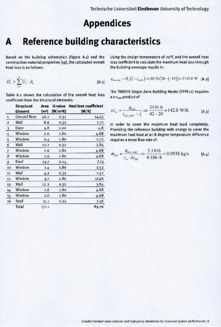
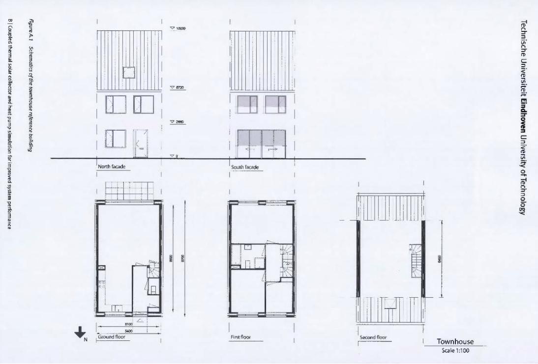
Bas!'d "" th ~ building sch~matics (Figure A.t) and the constfUcti"" material properties \191. the calculated o~~rall heat loss is as follows:
[A.l]
labl~ A.l shows the calculation of the o~eraM heat loss co..t/icit'nt from the structural elements:
Struttund Element
11 Wall 12 Window 1~ Wall 14 Window 15 Window 16 Roof
lotll
.... [m' l
,., 9·7
12.2 ,., ,., 31.1
' 7'.'
U ....... lue lW/mlK]
0 ·32
, '" 0.] 2 1.8 0
1.80
0.24
Hut loss <ol ffklen t lW/KJ
"}2 17.46
3.84 4.68
4.68
7-46
89.76
Using the design temperature of 20·( and the overall heat loss coefficient to calculate th e maximum heat loss through the building envelope results in:
Th e TRNSYS Single lone Building Model (iYPE12) require. a t.c ... product of
E:Cw
= qloM ::::) 314\.6 .. 142.8 W/K 1.\'11) .• ,.-1.. 42-20
lA.3]
in order to CO'Ier the maximum heat load completely. Providing the reference building with energy to coyer th e maximum heat load at an 8 degree temperature difference requires a mass flow rate 01:
. q ... ,,,,,, 3.1416 00938 c •• m", ., .::::) . "1318 - C
w ·!:"I$I1 4.186·8
• {' -
i • > • ! ,
! • i
, 0 , ,
f , ! 1 ! ! •
• • < , , • , i
, , ~
• 1
, , ,
[] []
[IJ '. ,-, , 1
I~h_
• ~
e .. . . , ' ' , , , . , , • , •
,
"'l-'
"" ;:;.. ,
"-', lill , I , ',e- i"" ,
~
I •• - , I G<~ 1'1<>« ,
.- II i I ~ []] OJ .-I H '~1 I ..
1_ f"""", -- ----
I I , !L .), -
" .i I' r-- >
, ;r
I
I
I
I
I
I
- )' , , "Ji ! ' il .' I L
!C["rT J-'h ' I
I
Townhouse Sui<!':l00

Technlsche Universlteit Eindhoven University ofTechnology
B Heat pump characteristics
Technische Universiteit Eindhoven University ofTechnology
C Dimensioning method for the V-GHX
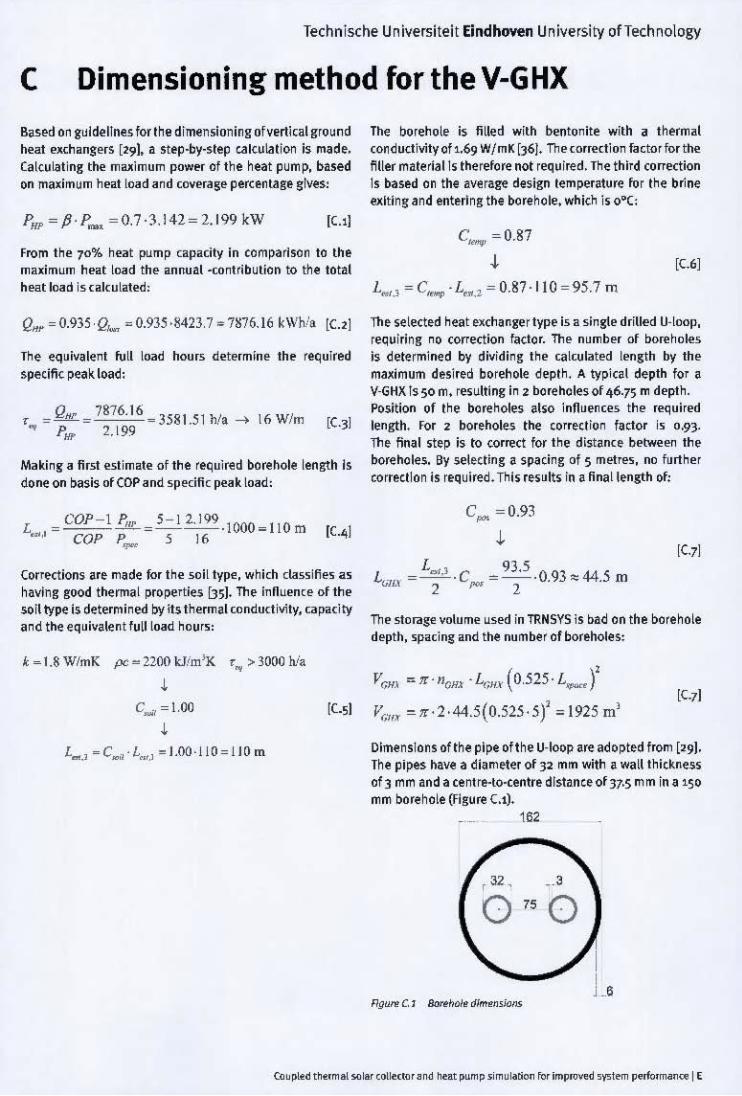
Based on guidelines for the dimensioning of vertical ground m.at exd1angers [291, a step-by-s tep catculation is made. Ca lculating tm. maximum power of the heat pump. based on maximum heat load and coverage percentage gives:
PHF = p. p_. = 0.7 ·3. 142 = 2.199 kW [Ll1
From tne 70% neat pump capacity in co mparison to the maximum heat load the annual -contribution to the total heat load is calculated:
QH~ = 0.935 'Q ... ~ 0.93~ ·8423,7 .. 7M76.16 kWh/l [Ui
The equivalent full load hour,; determin e th e required specific peak load:
,- =.fk:. = 7876.16 _ 3581 ~1 h1a .... 16 Wlm .. p~ 2. 199 .
Making a first estimate of the requil'l!d borehole length Is done on basis of COP and specific peak load:
L = COP-l.&~_ =S - 1 2.199 . 1ClOO _ 1l 0 m ie'i • ~, COP P 5 16 ., -
Corrections are made for tne soil typ~. which classifi es as having ~ood t~rmal properties 851. The influence of the soil type is determined by its therm al conductivity, capacity and the equivalent full load nours:
t _ l.8WlmK pc _ 2200kJim'K r .. > 3000hia ,
T~ borehole is filled with bentonite with a thermal conductivity of 1.69 W/mK (36). The correction factor lor the Mer material Is the refore not required. Tn e third correction Is based on the ave rage design temperature for tn e bnne exiting and entering tht borehole, which is o·C:
[C6]
L..,., = C_ ·L ••. 2 = 0.87· 110 =9~.7 m
Th e se lected neat exchanger type is a single drilled U· loop, requiring no correction factor. The number of ooreholes is determi ned by dividin ~ tne calculated length by the maximum desired borehole deptn. A typical depth for a V-GHX lS50 m, resulting in 2 boreholes of 46.75 m depth . Position of the borenoles also influences the requi red length. For 2 boreholes the correction factor is 0.93. Th e final step is to correct for tne distanc e betwe"" the boreho les. By selectin g a spacing of 5 metres. no lurther correction is required. Tnis results in a final length of;
C,.,. =0.93
• L(illJi. = L.., .• . C = 935 .0.93 '" 44.5 ill
2 ~ 2
The sto"'g:~ volume used in TRNSYS;s bad on the borehole depth. spacing: and the number of borehOles:
Vr,Hl '" 1f' nonx . L.,HJ/ (0,52~' L __ f C ... = i ,OO , [C51 V C,'IIX '" 1f. 2 .44.5(0.525. 5)' ,,1 925 m'
[C71
L ... , · C ... L"" , · LOO · jlO = jlO m Dime nsions of the pij)f of the U-Ioop are adopted from ['91. The pij)fs have a diam eter of 32 mm with I wall thic~ness of 3 mm and a centre-to-centre distance of 37.5 m m in a 150 mm bore hole (F 1 ~ure Cl).
162
•

Tethnlsdle Universiteit Eindhoven University of Technology
o TRNSYS input data
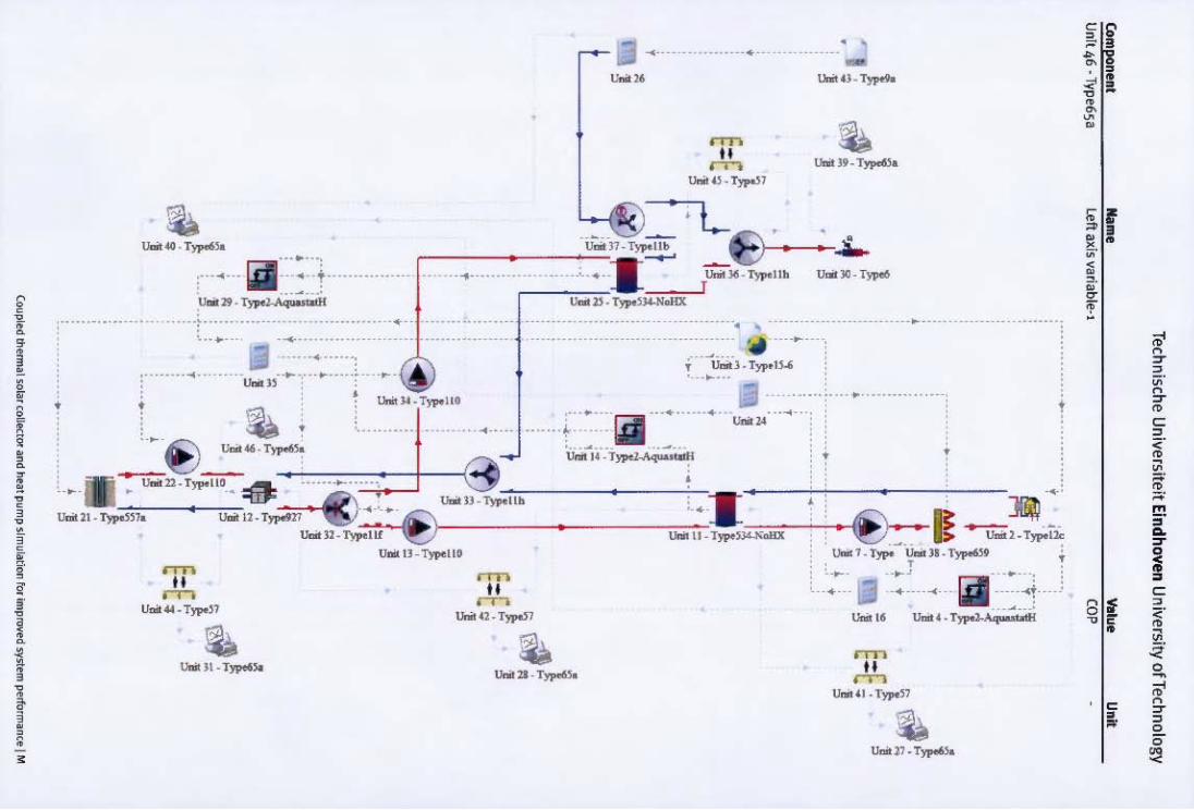
Thl'i appMd/x Uble$ Iht ~.amPlI!f'i and inpul fill 11th T1tMSV'S mocI~. v,lu", that are Inhftit~ '«1m othft ComponlHlt5 Of do fIOI deoA.tt hom the d ..... 1l1t Sf:ttinl'i af. I_,.,ltv fIOI.tp.tstntC'd. When a t omponlHll clots not dllYtf within t he ~fms, .tfftfl\(f is ma<ie to th ~ fi f5t occu ... lI<e 01 thlt compoo tnt 101 tltt k1 put \IlI1 ~f!i . FCl , t lil ri n cat Ion of t he components, 5d\~,lIIU 01 Iht sYSlem model'! Kcompany nth table .
Coo/jIIo<I _____ pwap " .. "_""' . :' od_~I G
Technische Universileil Eindhoven University ofTechnology
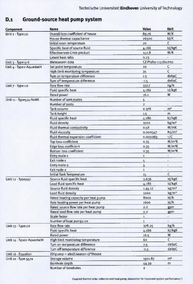
0.1 Ground·source heat pump system
High limit monitoring tempelllture 35 , Tum on tem[?('rature difference 1·5 deltaC Tum off t~mp~ratur~ difference -1,5 deltaC
Unit 7 - Typeuo Rate flow r!ie 3}H q/h Ruid spedfl< heat 4-'86 kJ/kgk Rated power 16.1 W
Unit u - Typ~S34·NoHX Number of tank n()(jes ,
Exit noc\e-2 , Initial Tank Temperature "
, Unit 12 - fY?e927 SoufC~ fluid specific heat 3.636 kJ/qK
Load Auld specific heat 4.186 kJ/kgK Source nuid density 1.45·12 kg:/m' Load nwid density 1000 k!/m' Rated heating capacity per h~at pump '00' ./h Rate heating power per heat pump "00 Wh Rated SOufC~ flow rat~ per ..... at pump '.' gpm Rat~d load flow rate per heat pump ... gpm
Scale factor , Numberofheat pumps on ,
Unit 13' Typello Rate flow rate 378.25 ks/h Fluid sp ~dfic heat 4.186 kJlksk Rate<! powe, 16.5 W
Unit '4 - Type2-AquastatH Hillh limit monitoring temperature " ,
Tw-n on tempe rature difference 2·5 deltaC
Tum off temperature difference '2.5 dellaC
Unit 16 - Egu~tion iSHpump - abs(Cseason·1)"lhouse Unit 21 ' Typ" 557a Storage volume 1921.87 m'
Borehole depth 44·39 m Number of I>orehol~s •

Technische Universitelt Eindhoven University ofTechnology
Unit 22· Typeuo
Unit 24 ·Equation
Unit 25 • Tvpe534·NoHX
Unit 26· Equation
Reference temperature Auld spedftc heat Auid density Number of 5imulation reap.; ,
Tankheisht Auld speCific h~at Auld density ,
, , ,
Nb. 01 right·a,us variables left axis minimum leftaxismarim um Right axi5 minimum
left axis ¥aria~e·3
, 3.636 1045.12 ,
1.5
4.186 1000
• ·25
75
TSHtank.in
C klf!<gK kgfm'
m
kl/kgK kgfm'
Technische Universiteit Eindhoven University of Technology
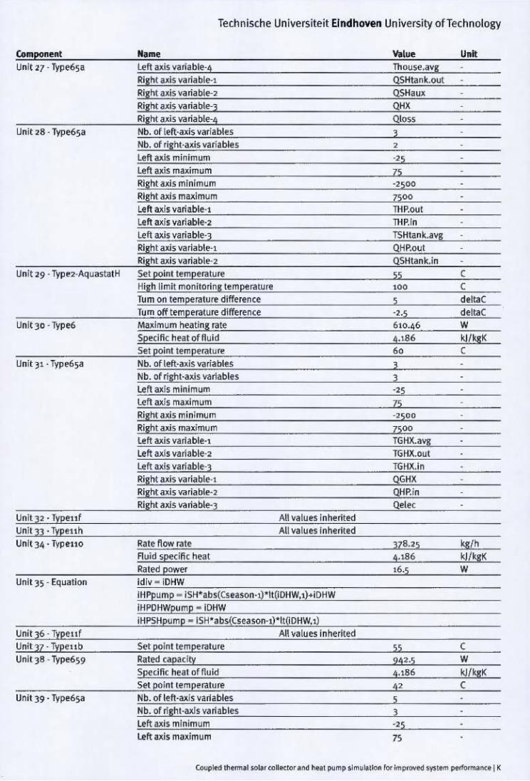
left axis variable-3 Right axis variable"' Right ui5 variable'2
Unit 29 -Type2-Aqua5tatK Set point temp!rawn'
Unit30 -Type6
l< UnltJ4' Tvpelto
UnitJ6 Typellf Unit 37 Typellb Unit 38 -TVpe659
Unit 39 ' Type6sa
High limit monitoring temperature Tum on temperatun' difference Tum off temperature difference
, , i i
,; ,;
Set point te mperature Rated capacity Specific heat of fluid Set point temperature Nb. of left·uis variables Nb. of rilht·ax1s variables left axis minimum left axis maximum
An values inherited
TSHtank.aVIJ QHP.out QSHtank.in 55 >0, 5 '2.$
55
942·5
4.186
" 5 )
'25 ,.,
C C deltaC deltaC
c w kJ/kgK c
Technische Universiteit ElndhO'ffln University ofTechnology
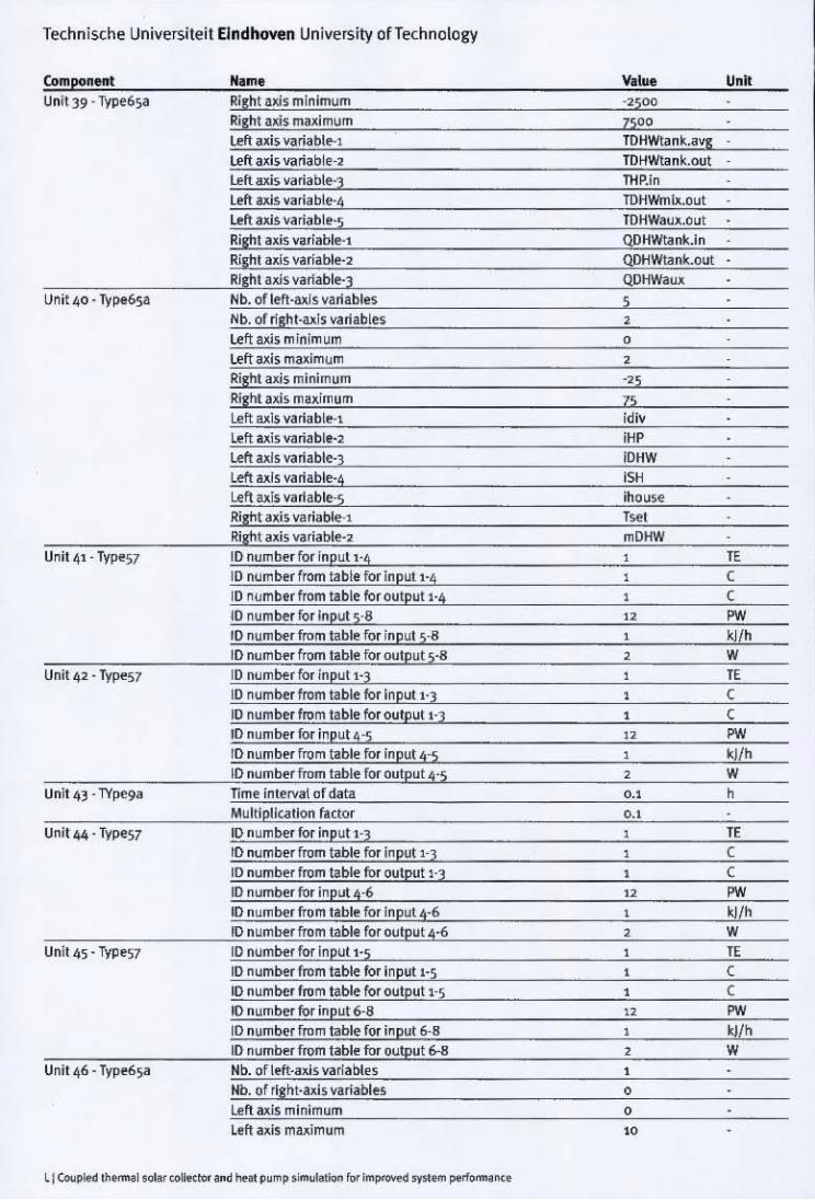
Unit 42. TI'P"57
Nb. of right·axls variables Lett Mis minimum Left axis maximum Right axis minimum
, , ,
1 • ! ! I ! ! " < , " • , <
! , ! l i t •
.... ~ ... , .. , .. ... -
" ""
• u... .. . T)'J'OMo.
.......... '.-
r-=" ,. ......... ..-
UtItIIl_ TypellO
Unil2I_T~
• --..
• •
-------.- -. ~ ------------
'4 --0-
,;--~tW-l. T_U." - -0-'"
II •
•
'-..-'---.--
, , • ~ •
~ , ~ , •
p' •••••••• , ~ • t C ,
• < • , • • • ~ ~ ~ 0
-.-----<--_ ... --,
1jI ----~-~:--II u.;, 16
~ , c
8 , <" • • !:!l.
'" 0 -~ , ~ , 0 0
~

Technische Universiteil EIndhoven University ofTechnology
0.2 Parallel solar collector & ground-source heat pump system
Component Unit2· Typelb
Unit 4 . Typello
Unit ~. Type2b
Unit 7· TypeS34·No H)(
Unit 9· Equation Unit 12· Typet5·2
Unit 13· Typeub Unit 14· Typellh
Nlme Collector area Auld spedfk heat Tested now rate ,
2nd-order lAM Rate lIow rate Auld spedllc heat Rated poWi!r High limit cut·out Upper dead band dT Lower dud band dT
Entry node·2 E>.it node-2 Entry node·3 W node-3 Initial Tank Temperature
Meteonom1 data Slope of surface Set point temperature
10 number from table for ootpU!'·; 10 number for input s· 7 10 number from table for input 5"7 10 number from table for output 5·7 10 number for Input 8 10 number from table for input a
Seoe D.,· Unit 26
All values Inherited
v ... , 4·52 4.'86 250 .92
-0.107
250·92 4.,86 15·2
" , ,
, , , , "
v., m' kJ/qK
'<I'
q/h kJlqK W ,
, CZ· Pra ha·llSl8 o.t m2 45.J deg!fl!5
" ,
, , " .. ,
"" , W
'1 '" , kJlhm'

Component Unit 18 · Types? Unit 19' Type6 Unit 20· TypeS7
Unit 11· Type6sa
-Typeno
Technische Universiteit Eindhoven University ofTechnology
.. -to nymber from tabte for ootput 8
ID nymberfor input 1-3 ID number from table for input I ' ] ID number from table for Oylputl'3 10 nymber for input 4-5 10 nymber from table for input 4'5
ID number nom table for outPUt 4-5 Nb. of left'a~i$Variable5
, ,
Exit node·, Entry node'2
,
See D.l Unit )0
"' .. , , , , " , , ,
, ,
'" W/m'
" (
( ,.. "/h W

Technische Universiteit Eindhoven University of Technology
iSCdivPl1~r _ iSCDHW
Unit 4Z·l'ypel1o See 0 .• · Unit 34 Unit 48 ·l'ypeno See 0 .• · Unit '3 Unit 49 . Typeuh All values Inherited Unit 50' Typello Rate now rate 378.25
Auid 5Pecine heat 4.,86 Rated power .6.5
Unit 5" TYP!110 Rate How r~te 378.25 fl Uid spedne heat 4.186 Rated power 16.5
Unit 5" Typel10 Rate now rate 378•25
Left axis maximum 2 Right axis minimum 0 R'lht axis maximum 2 Left axis variable·, iHPdiv
""'
c
kgth kJtkgK W
kgth kJtkgK W
kgth kJlkgK W
kgth kJtkgK W ksth

Technische Universiteit Eindhoven University of Technology
Right axi, varf.ble-3

•
. -• " •
• • •
• • • , _ .. , • ,
,: .. ".- ..,.,.. .. ,
•
•
• • • •
• •
-... -
• • • - " • •
"",,- .. _t~
•
•
- " •
--
•
iii , T_ " , .
iii •
...,..' . or
• • • . ' • • • -"
•
• , 'J
--~-
• • '. • • _ ..
, . " -- .,.--,."..,'"
,
• --~-
•
•
! •
! , ! I , t ! I • • • •
~ I j I -
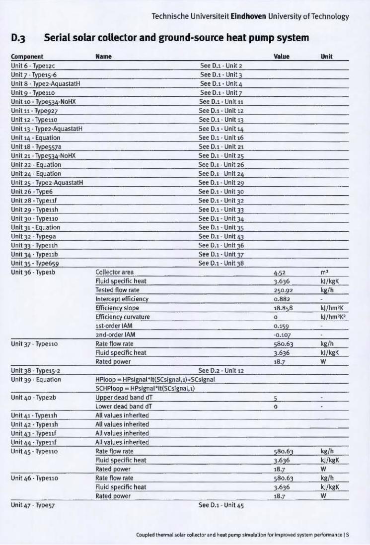
Technische Universiteit Eindhoven University ofTechnology
0.3 SeriaL soLar collector and ground-source heat pump system
" I Typelb
Unit 40 -Typub
Un it 47-Tvpe57
Auid spedflc hellt Rated power
'. ,.
See 0.1- Unit 45
) .6)6
18.7 kJfkgK W
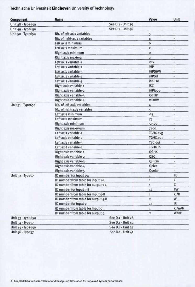
Technische Universite it Eindhoven University ofTechnology
Component Unit 48 . Typ!65~
Unit 49 ' Typ"65~ Unit 50' Type653
Unlls5 ' Type6S8 Unit 56· Type57
Nlme
Nb. of left-axis variables Nb. of right-u/s va~ab\es Left lUis minimum Left axis miUlmum Right axis minimum Right axis ma..;,(mum ,
S~ 0.1' Unit 39 See 0.1 ' Unil46
See 0.1- Unit 27 See 0.1 - Unit ~I
Yo ... u ••
, • , , , ,

f , , ! • • , • , • , _. • , , • , , < • • • • ! I , I ! • "
. . ... --,
_ ,,".' • .t.,,_~ I • r-- ;
• • • ~-:- IiI '" ....._T_
~
,JI., ... " ,_,
, I .
•
, •
•
• iii •
• - ".",",
• iii - ~-~ ,
.... .. --
•
-•
• • • • I """,. ~ •
• • --"-
, .. -. ...... ~ ... -•
• • ,-+ • - " •
--,"-
•
•
• •
• iii . , • ..... . _1,..., . or


![Bike train system [eindhoven]](https://img.pdfslide.us/doc/110x75/55a51e7b1a28ab565a8b4902/bike-train-system-eindhoven.jpg)
![Seeker [ehv3] Eindhoven](https://img.pdfslide.us/doc/110x75/5594536e1a28abc84f8b4770/seeker-ehv3-eindhoven.jpg)