Embed Size (px)
Citation preview

Eindhoven University of Technology
MASTER
Comparing a code-based implementation with a model-driven implementation of a cloudcomputing platform (PHP vs Mendix)
Guillen Becerril, M.G.
Award date:2011
Link to publication
DisclaimerThis document contains a student thesis (bachelor's or master's), as authored by a student at Eindhoven University of Technology. Studenttheses are made available in the TU/e repository upon obtaining the required degree. The grade received is not published on the documentas presented in the repository. The required complexity or quality of research of student theses may vary by program, and the requiredminimum study period may vary in duration.
General rightsCopyright and moral rights for the publications made accessible in the public portal are retained by the authors and/or other copyright ownersand it is a condition of accessing publications that users recognise and abide by the legal requirements associated with these rights.
• Users may download and print one copy of any publication from the public portal for the purpose of private study or research. • You may not further distribute the material or use it for any profit-making activity or commercial gain

Reengineering a Cloud
Computing Platform using Model based Technologies
Manuel Gustavo Guillen Becerril
November 2011
ii
Comparing a code-based implementation with a model-driven implementation of a Cloud Computing Platform (PHP vs Mendix)
By
Manuel Gustavo Guillen Becerril
A thesis submitted in partial fulfillment of the requirements
for the degree of
MASTER OF SCIENCE Business Information Systems
Eindhoven University of Technology
2011
Supervisor: Dr. Ir. Pieter Van Gorp Examination Committee: Dr. Alexander Serebrenik Dr. Marco Comuzzi Dr. Ir. Pieter Van Gorp
Eindhoven, November

i
ACKNOWLEDGEMENTS
This thesis is the result of my graduation project, which concludes the master program
Business Information Systems at the Eindhoven University of Technology. The project
was carried out within the Information Systems group at the School of Industrial
Engineering.
First of all I want to thank my sister Kalina Guillen and my parents Manuel Guillen and
Irma Becerril. Without their support and care this would never have even begun. I
would also like to thank all my friends and relatives in Mexico for their constant
motivation, help in many situations and believe in me.
I would like to extend my gratitude to my supervisor, Pieter Van Gorp for sharing his
wisdom and guidance for the completion of this work; to Alexander Serebrenik for his
comments and suggestions after my interim presentations and being part of my
evaluation committee; and to Marco Comuzzi for his feedback and also being part of
the evaluation committee.
Furthermore, I would like to show my gratitude to my best team-mates, class-mates and
friends Hector Diaz and Santiago Hernandez for all their help and support through
these two years in Netherlands. To everyone I have met in Eindhoven who cared and
supported me in spite so many difficulties.
Finally, pursuing this master program and writing this thesis would not have been
possible without the help of God.
MANUEL GUILLEN

ii
ABSTRACT
Model Driven Development (MDD) has matured over the last few years and is now
becoming an established technology. One advantage that is promoted by the MDD is
the improved maintainability during the systems evolution over conventional
development approaches. The elements that are used in this approach (metamodels and
transformations) need to be handled different when it refers to maintainability
assessments in comparison to code-based development. However there is still a lack of
a comprehensive study about the impact of model-driven development approach on the
maintainability of software. This thesis presents work towards the finding of
appropriate approach and metrics for measuring maintainability within model-driven
environment when compared to code-based approach in the domain of Web
Information Systems.
In order to accomplish the assignment, the project is divided in two parts. The first part
is about the analysis of current solution which name is SHARE and is a code-based
solution implemented with PHP. The analysis is part of a case study that consists in (1)
the model capture (reverse engineering), (2) the problem resolution and, (3) the
implementation (forward engineering). Mendix is used as a MDE (Model-Driven
Engineering) tool for this project.
For the second part of the study, it is necessary to evaluate and compare both solutions
and determine which one supports the implementation of new features better
(maintenance). A new framework is created for that purpose that classifies the solutions
in four levels: conceptual level, design level, language level, and tool level. For the
language level, the GQM framework and the MVC architecture are combined in order
to obtain valuable metrics and be able to evaluate model language versus code
language.
Finally, results are obtained and even the model-driven arises as to be better than code
based implementation, there are certain details that make interesting to perform this
study in different domains using for evaluation the framework within the development
of this project.

iii
TABLE OF CONTENTS
LIST OF FIGURES ............................................................................................................................................. V
LIST OF TABLES ............................................................................................................................................... VI
1 INTRODUCTION ...................................................................................................................................... 1
1.1 PROBLEM DEFINITION ................................................................................................................................. 1
1.1.1 Evolution of Programming Languages and Software Development Platforms ....................................... 1
1.2 MOTIVATION ............................................................................................................................................... 5
1.3 RESEARCH METHOD .................................................................................................................................... 6
1.4 STRUCTURE OF THE REPORT ........................................................................................................................ 8
2 PRELIMINARIES ....................................................................................................................................... 9
2.1 WEB BASED SYSTEMS .................................................................................................................................... 9
2.2 MAINTAINABILITY ..................................................................................................................................... 10
2.2.1 Factors ................................................................................................................................................... 10
2.2.2 Difference between Maintenance and Maintainability.......................................................................... 11
2.3 RELATED WORK ........................................................................................................................................ 11
2.4 MODEL-DRIVEN ENGINEERING ................................................................................................................ 13
2.5 DOMAIN SPECIFIC LANGUAGES (DSLS) ................................................................................................... 15
2.6 UML DIAGRAMS ....................................................................................................................................... 16
2.7 BUSINESS PROCESS MODEL AND NOTATION ............................................................................................ 17
2.8 MENDIX...................................................................................................................................................... 18
2.8.1 Characteristics ....................................................................................................................................... 19
2.8.2 Competitors............................................................................................................................................ 20
2.8.3 Justification ............................................................................................................................................ 21
2.9 PHP ........................................................................................................................................................... 22
2.9.1 Characteristics ....................................................................................................................................... 23
2.9.2 Competitors............................................................................................................................................ 24
2.9.3 Justification ............................................................................................................................................ 25
3 CASE STUDY ........................................................................................................................................... 27
3.1 SHARE ...................................................................................................................................................... 27
3.2 CASE STUDY CHARACTERISTICS ................................................................................................................ 29
3.2.1 Use cases ................................................................................................................................................ 31
3.2.2 Boundaries ............................................................................................................................................. 32
3.3 EXECUTION ................................................................................................................................................ 33
3.3.1 Reverse Engineering .............................................................................................................................. 36
3.3.2 Forward Engineering ............................................................................................................................. 37
3.4 COMPARISON ............................................................................................................................................. 47
4 COMPARISON FRAMEWORK ............................................................................................................. 48

iv
4.1 REASON ...................................................................................................................................................... 48
4.2 DEFINITION OF FRAMEWORK..................................................................................................................... 49
4.2.1 Conceptual classification ....................................................................................................................... 49
4.2.2 Design classification .............................................................................................................................. 50
4.2.3 Language classification .......................................................................................................................... 52
4.2.4 Tool classification .................................................................................................................................. 58
4.3 NEW FRAMEWORK ..................................................................................................................................... 61
5 EVALUATION WITH FRAMEWORK .................................................................................................. 62
5.1 CONCEPTUAL EVALUATION ...................................................................................................................... 62
5.2 DESIGN EVALUATION ................................................................................................................................ 63
5.3 LANGUAGE EVALUATION .......................................................................................................................... 70
5.4 TOOL EVALUATION .................................................................................................................................... 76
5.5 SUMMARY .................................................................................................................................................. 77
6 CONCLUSIONS ...................................................................................................................................... 80
7 BIBLIOGRAPHY ...................................................................................................................................... 83
APPENDIX A .................................................................................................................................................... 92
APPENDIX B ..................................................................................................................................................... 94
APPENDIX C .................................................................................................................................................. 102
APPENDIX D .................................................................................................................................................. 107
APPENDIX E ................................................................................................................................................... 108
APPENDIX F ................................................................................................................................................... 112
APPENDIX G .................................................................................................................................................. 113
APPENDIX H .................................................................................................................................................. 118
APPENDIX I .................................................................................................................................................... 122
APPENDIX J .................................................................................................................................................... 123

v
LIST OF FIGURES
FIGURE 1: LEAPS ON SOFTWARE DEVELOPMENT........................................................................................................... 5
FIGURE 2: REPRESENTATION OF MODEL-DRIVEN INITIATIVES ..................................................................................... 14
FIGURE 3: UML 2.4 DIAGRAMS ................................................................................................................................... 17
FIGURE 4: FLOW AND CONNECTING OBJECTS ............................................................................................................... 18
FIGURE 5: TOP LEVEL OVERVIEW OF MENDIX ARCHITECTURE ................................................................................... 20
FIGURE 6: PHP AND SERVER ARCHITECTURE ............................................................................................................. 24
FIGURE 7: SHARE ARCHITECTURE MODEL ................................................................................................................ 28
FIGURE 8: USE CASE DIAGRAM OF ORIGINAL SYSTEM .................................................................................................. 30
FIGURE 9: NEW USE CASES ......................................................................................................................................... 31
FIGURE 10: FORWARD, REVERSE AND REENGINEERING .............................................................................................. 34
FIGURE 11: AMDD LIFECYCLE .................................................................................................................................... 35
FIGURE 12: MENDIX DEVELOPMENT METHODOLOGY ................................................................................................ 35
FIGURE 13: INITIAL DOMAIN MODEL .......................................................................................................................... 38
FIGURE 14: VIRTUAL DISKS IMAGES FORM .................................................................................................................. 40
FIGURE 15: NEW VDI FORM ........................................................................................................................................ 40
FIGURE 16: UPDATE VIRTUAL DISK IMAGE ................................................................................................................. 41
FIGURE 17: ERRORS IN ERROR LIST .............................................................................................................................. 42
FIGURE 18: APPROVE MUTABLE DISK REQUEST MICROFLOW ..................................................................................... 44
FIGURE 19: CONFIGURING SECURITY IN MENDIX ........................................................................................................ 45
FIGURE 20: HOME PAGE RUNNING IN A BROWSER ....................................................................................................... 46
FIGURE 21: CONCEPTUAL DATA MODEL VS DOMAIN MODEL .................................................................................... 66
FIGURE 22: ENUMERATION TYPES IN MENDIX ............................................................................................................ 67
FIGURE 23: PHP UPDATE IMAGE METADATA SCREEN-FLOW ..................................................................................... 68
FIGURE 24: MENDIX UPDATE IMAGE METADATA SCREEN-FLOW ............................................................................... 68

vi
LIST OF TABLES
TABLE 1: MDD TOOL SELECTION CRITERIA ................................................................................................................. 21
TABLE 2: CONCEPTUAL LEVEL EVALUATION ................................................................................................................ 50
TABLE 3: CONCEPTUAL DESIGN COMPARISON ............................................................................................................. 51
TABLE 4: NAVIGATION AND PRESENTATION COMPARISON ......................................................................................... 52
TABLE 5: RELATIONSHIP BETWEEN FACTORS AND CRITERIA FOR MAINTAINABILITY ................................................... 53
TABLE 6: MVC COMPARISON....................................................................................................................................... 57
TABLE 7: SUMMARIZED RESULTS OF CRITERIA BY AREA .............................................................................................. 58
TABLE 8: TABLE FOR TOOL EVALUATION ..................................................................................................................... 61
TABLE 9: NEW COMPARISON FRAMEWORK .................................................................................................................. 61
TABLE 10: COMPLETENESS AND CORRECTNESS ........................................................................................................... 62
TABLE 11: CONCEPTUAL SIMILARITY COMPARISON .................................................................................................... 63
TABLE 12: ENTITIES IN BOTH DESIGNS ......................................................................................................................... 63
TABLE 13: RELATIONSHIPS IN BOTH DESIGNS .............................................................................................................. 64
TABLE 14: QUANTITATIVE COMPARISON OF NAVIGATION AND PRESENTATION DESIGNS .......................................... 69
TABLE 15: QUALITATIVE NAVIGATION AND PRESENTATION DESIGN COMPARISON PER USE CASE ............................. 70
TABLE 16: CONCEPTUAL, NAVIGATION AND PRESENTATION DESIGN SUMMARIZED RESULTS ................................... 70
TABLE 17: MODEL COMPARISON AT LANGUAGE LEVEL ............................................................................................... 71
TABLE 18: VIEW COMPARISON AT LANGUAGE LEVEL ................................................................................................... 74
TABLE 19: CONTROL COMPARISON AT LANGUAGE LEVEL ........................................................................................... 75
TABLE 20: EFFECT OF MVC OVER CRITERIA ................................................................................................................ 75
TABLE 21: TOOL MATRIX COMPARISON FOR TOOLS ..................................................................................................... 77
TABLE 22: COMPARISON OF BOTH TECHNOLOGIES ...................................................................................................... 78

vii

1
1 Introduction
In this chapter the problem addressed in this thesis will be defined, followed by the
motivation and the research method for the project. In the end, an outline of this work is
presented.
1.1 Problem Definition
For Software Development, when it is required to create new software, besides other
aspects as human resources, budget, etc; a programming language must be selected. In
computer science, the evolution of these languages occurs really fast. When a language
or technology has been well known and the people involved have a good command of
it, there is a new one that appears or even the same can have ramifications or subtypes
that make the maintenance of the systems really complicated. Sometimes these have to
be entirely rebuilt and their integration is hard [1].
Model Driven Engineering has appeared as new method with the promise of a more
portable and stable way for developing and maintaining software [2] [3] [4]. Several
studies have tackled this topic from different points of view (i.e. impact productivity
and quality [5], industry [2]). Nevertheless the questions regarding maintainability are
not fully answered.
1.1.1 Evolution of Programming Languages and Software Development Platforms
In order to describe the evolution of the PL’s (programming languages) and platforms,
it is necessary to provide a brief overview of the ‚generations‛ of programming
languages. Afterwards, the difficulties and leaps during the evolution will be exposed.

2
1.1.1.1 Programming languages
In the computer industry, these abbreviations are widely used to represent major steps
in the evolution of programming languages. Ghazaleh et al. [6], provide a concise and
brief description of the ‚generations‛:
“Object code is what is known as a first-generation programming language or 1GL. Assembly
language is called second-generation language or 2GL. 3GL or third-generation language is a
high level programming language, such as PL/I, C, or Java and may or may not be an OOPL
(Object Oriented Programming Language). A compiler converts the statements of the specific
high-level programming language into machine language. A 4GL or fourth-generation language
is designed to be closer to natural language than a 3GL language. 5GL or fifth-generation
language is programming that uses a visual or graphical development interface to create source
language that is usually compiled with a 3GL or 4GL language compiler”.
1.1.1.2 Leaps during the evolution
To put MDE in context a brief overview of the modeling paradigms is presented.
During the evolution, there have been difficulties and obviously leaps on software
development.
The first recognizable modern, electrically powered computers were created in the
1940s (e.g. ENIAC) [7]. Those were programmed using 1st and 2nd generation languages
(machine code and assembly languages).
In the 1950s, the first three modern programming languages were developed. The
descendants are still in widespread use today: FORTRAN, LISP and COBOL [8]. These
languages are considered 3rd generation languages (3GL) and represent a significant
advance on the platform independence and the abstraction level (first leap).
The period from the late 1960s to the late 1970s brought a major flowering of
programming languages. Most of the major language paradigms now in use were
invented in this period and it is considered as the period where the structured
programming methodology appeared and was used. Due to the intensive usage of such
methodology, this period of time can be considered as the second leap on software

3
development [9]. Some of the languages were: Logo, Pascal, C, Basic, Smalltalk. In the
late of this period, one of the most transcendent model-based languages appeared:
Entity-Relation [10].
The 1980s were years of relative consolidation in imperative languages. Rather than
inventing new paradigms, all of these movements elaborated upon the ideas invented
in the previous decade. One important new trend in language design was an increased
focus on programming for large-scale systems through the use of modules, or large-
scale organizational units of code [9]. Examples of the languages created during these
years are: C++, Eiffel, Erlang, FL.
The spread of functional languages began during the era of 90’s. A big driving goal for
development of these languages was the increase of programmer productivity [11].
Many "rapid application development" (RAD) languages emerged too, which usually
came with an IDE (integrated development environment) and were descendants of
older languages. This period could be considered as the third leap on software
development. Scripting languages came to be the most prominent ones used in
connection with the Web [11]: Python, Visual Basic, Java, Delphi, Java Script, PHP.
During the last decade, the trends were oriented to: Component-oriented software
development, increase emphasis on distribution and mobility, integration with
databases, support for Unicode, mechanisms for adding security and reliability, XML
for graphical interface [12]. Some important languages developed during this period
include: C#, Visual Basic .NET, F#, Scala, Factor.
Afterwards, the number of languages and platforms increased. For the same languages,
a lot of variations appeared without mentioning the different libraries that were created.
In order to have a better organization of these libraries providing a defined application
interface, the software frameworks were established. According to Johnson [13], a
framework is ‚a set of classes that make up a reusable design for an application or, more
commonly, one tier of an application”. For example; EJB, Hibernate and Sprint are
frameworks designed for J2EE (Java 2 Enterprise Edition) [13]. But since their creation,
there have been different versions for each one and they have been competing not only
with other frameworks but also between them due to the growth of platform
complexity and the rapid evolve of these platforms.

4
Because of these type of problems, the software industry is reaching a complexity
ceiling where next-generation platform technologies, such as Web services and product-
line architectures, have become so complex that developers spend years mastering (and
wrestling with) platform APIs and usage patterns, and are often familiar with only a
subset of the platforms they use regularly [3].
Additionally, it is important to take in account the programmers’ mobility between
companies that have collaborated to have a lack of stability and interoperability for
different types of software. The need for something more stable and easy to use came
up; so then the modeling approach gained force and promises to solve this, introducing
a stable modeling layer on the top.
Twenty-one years after ER, in 1997, the first version of UML was presented (UML 2.0
dates from 2005). Today, UML is used as the standard model-based language for
software development. ER and UML are the roots of MDE. MDE was born in the earlier
years of 2000s with the launch of Model-Driven Architecture.
Languages of 4th (e.g., SQL) and 5th (e.g., Prolog) generation (4GL and 5GL) have a
representation inside MDE. Domain Specific Languages (DSL) are the normal evolution
of 4GL, and constraints-based languages like Object Constraint Language have a clear
correspondence with 5GL [14]. What distinguishes MDE from the ‘fourth-generation’
and domain specific languages of the past is the aim at a systematic approach, with
supporting technologies, to the construction of models and modeling languages such
that these activities can be undertaken by the ‘average’ software developer and
integrated in the software development process [15].
MDE offer a promising approach to address the inability of third-generation languages
to alleviate the complexity of platforms and express domain concepts effectively [3].
Nowadays, MDE continues getting more and more relevance each year. So, comparing
the previous leaps with the current state of MDE it is possible to think that MDE could
be the next leap in software development [16].
5
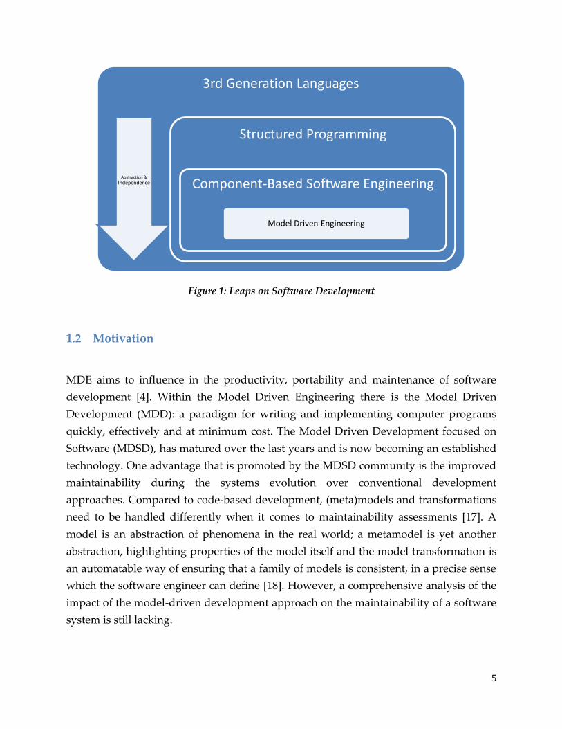
Figure 1: Leaps on Software Development
1.2 Motivation
MDE aims to influence in the productivity, portability and maintenance of software
development [4]. Within the Model Driven Engineering there is the Model Driven
Development (MDD): a paradigm for writing and implementing computer programs
quickly, effectively and at minimum cost. The Model Driven Development focused on
Software (MDSD), has matured over the last years and is now becoming an established
technology. One advantage that is promoted by the MDSD community is the improved
maintainability during the systems evolution over conventional development
approaches. Compared to code-based development, (meta)models and transformations
need to be handled differently when it comes to maintainability assessments [17]. A
model is an abstraction of phenomena in the real world; a metamodel is yet another
abstraction, highlighting properties of the model itself and the model transformation is
an automatable way of ensuring that a family of models is consistent, in a precise sense
which the software engineer can define [18]. However, a comprehensive analysis of the
impact of the model-driven development approach on the maintainability of a software
system is still lacking.
3rd Generation Languages
Abstraction & Independence
Structured Programming
Component-Based Software Engineering
Model Driven Engineering

6
Maintenance is one of the major cost factors in software development [19]. MDSD
claims to provide aid in reducing these costs. Though, currently it still needs to be
validated whether MDSD really improves the maintainability of a system. For models
and transformations the conventional code metrics cannot be applied to obtain
meaningful results. For example, it does not make sense to take the lines of code metric
of generated code into account to measure its maintainability [17]. Another important
aspect that needs to be accounted for is the comparability of the metrics to those of non-
model-driven approaches to decide if and in which scenarios such an approach is
beneficial to maintainability costs [17].
The intention will be to evaluate the maintainability and the concrete software
development adopting a MDE approach, using a common case study. For this, an
evaluation framework will be designed to compare the model-driven approach against
a code-based solution.
1.3 Research Method
For this project, case study was selected a research method. According to Wynekoop
and Russo [20], a case study is an “intensive evaluation of small samples using multiple
methods where there is no statistical or experimental control”. This method was chosen
because in contrast to surveys, typically the number of units studies in a case study is
many less than in a survey, but the extent of detail available for each case should be
greater. As compared with an experiment, the case study researcher has much less
control over the variables, than if an experiment were used to investigate a situation. In
a survey data may be collected from a number of organizations (software solutions in
this case) in order to generalise to all other organisations of the same type. In contrast in
a comparative case study across a number of different organisations, the objective is to
compare or replicate the organisations studied with each other in a systematic way, in
the exploration of different research issues [21]. Eisenhardt [22] also mentions that a
case study is useful in early stages of research on a topic or when a fresh perspective is
needed, whilst the latter is useful in later states of knowledge.
The case study will be a code-based web application with PHP over a cloud computing
platform called SHARE. This system is an online workflow system to request access to a
group of virtual machine images and also to start a virtual machine for purposes of

7
evaluation, making possible to create a virtual machine image containing the research
software and related documentation and publish it to a group of users [23].
This solution will be re-implemented with a Model Driven tool, applying reverse
engineering to obtain the requirements of the system and capture the model of the
solution. Then, forward engineering will be applied to construct the new system with
Model Driven Development techniques and will be compared with the current solution
based on specific features or use cases that have implied modification of the system.
Goals of the project
The main goals of this study are:
Reengineer the current code-based solution in order to have a new
implementation based on Model-Driven Architecture (MDA).
Classify, compare and evaluate both solutions according to a new designed
framework.
The framework should be applicable to other solutions as well.
The result of this project should generate a prototype of the new solution implemented
following a MDA and come up with results and possible recommendations about the
reengineering process of a code based application using a generic MDE tool. It is
important also to evaluate if this prototype facilitate changes (modify current features,
add features, delete features, etc.) more easily, since otherwise, it is less agile to build
information systems with it. So then, the maintainability of such new system will be
evaluated with metrics.
Research Questions
Based on the goals of the project the general research question can be formulated as
follows:
Does the model-driven solution support the implementation of new features
better than the code-based solution?

8
o Is a generic MDE tool suitable for the re-implementation of a code-based
prototype?
1.4 Structure of the report
The rest of the report is structured as follows. In Chapter 2 we provide an overview of
related work, an explanation about two concepts: Maintainability in web applications
and Model Driven Engineering. Furthermore, the technologies used for the developing
of this project will be exposed: Mendix and PHP. In Chapter 3 it is described the case
study used, its characteristics and the methodology used in this study that includes the
details for the implementation of the new solution. In Chapter 4 the framework used to
evaluate is described and the results obtained are analyzed on Chapter 5. Final
discussions and closing remarks are presented in Chapter 6.

9
2 Preliminaries
In this chapter a general explanation about the type of information systems used for this
study followed by maintainability concepts will be provided. Subsequently, a brief
overview of the related work will be exposed. After that, the Model Driven Engineering
concepts will be defined, including Model Driven Development and Model Driven
Architecture. Then, a description about DSLs, UML and BPMN will extend concepts
from OMG. The chapter will finalize explaining what is Mendix and PHP, including
their characteristics, competitors and the reasons to choice them as technologies for this
project.
2.1 Web based systems
A web application as a software system based on technologies and standards of the
World Wide Web Consortium (W3C) that provides web specific resources such as
content and services through a user interface, the web browser [24].
Web applications are build on the infrastructure of the World Wide Web and therefore
utilize web specific technologies, standards and languages. These include technologies
and standards of the W3C as HTTP, HTML, CSS and XML. They also include web
specific technologies and languages as Ajax and JavaScript. Because of the use of a web
browser as user interface web applications are platform independent.
The growth of the World Wide Web has already a significant impact in many sectors:
business, commerce, industry, research, etc. Many legacy information and database
systems are being migrated to the Internet and the Web environments (Web
Information Systems) [25]. This type of system have become more pervasive than
client/server systems did few decades ago, with an exponentially higher impact on our
lives, simply because the Web has the potential of reaching a much wider audience than
client/server systems based on proprietary networks [26].
However, in most cases, the development approach used for Web-based systems has
been ad hoc, and Web-based systems have been kept running through a continual
stream of patches. In the absence of disciplined process for developing Web-based
systems, we may face serious problems in their successful development, deployment,

10
operation of and 'maintenance' [25]. Model Driven Development could be an alternative
solution for this type of problems but specially maintainability.
2.2 Maintainability
In the following subsections, some factors that affect the maintainability on web
applications will be described and also the difference between maintenance and
maintainability will be defined.
2.2.1 Factors
Following the studies and recommendations of [27] [28], there are four important
factors for maintainability: modifiability, testability, understandability and portability.
In a case study performed by Stella et al. [29], these factors are applied to compare
maintainability of Web Applications on J2EE, .NET and Ruby on Rails in. A brief
description of each factor is the following [27] [29]:
Modifiability is the extent to which the software is able to incorporate changes.
Testability is the extent to which the software allows the establishment and
evaluation of its acceptance criteria.
Understandability is the extent to which the software is comprehensible to the
maintainer.
Portability is the extent to which the software can be easily and effectively
operated in a variety of computing environments.
For this study, those four maintainability criteria will be used as a base to create the
evaluation framework in combination with GQM technique (Goal-Question-Metric);
having on mind the implicit modifications that must be done when it is necessary to
compare certain aspects of both solutions (i.e. Lines of Code (LOC) from the code based
solution vs number of entities in the metamodel from the model-driven solution).

11
2.2.2 Difference between Maintenance and Maintainability
Definitions for software maintenance and maintainability are many, but they are fairly
consistent in scope and intent. The definitions of the IEEE are [30]:
Maintenance: The processes of modifying a software system or component after
delivery to correct faults, improve performance or other attributes, or adapt to a
changed environment.
Maintainability: The ease with which a software system or component can be
modified to correct faults, improve performance or other attributes, or adapt to a
changed environment.
Consistent with these definitions, the maintenance process can be divided into three
areas of focus [30]:
Corrective maintenance: Maintenance performed to correct faults in hardware
and software.
Adaptive maintenance: Software maintenance performed to make a computer
program usable in a changed environment.
Perfective maintenance: Software maintenance performed to improve the
performance, maintainability, or other attributes of a computer program.
In this study, the motivation to use Model-Driven Engineering as a development
technology is to decrease the maintenance of the current web system but increase the
maintainability at the same. Therefore, it is important to have the concept of both terms
clear for the evaluation and the analysis of the results in order to have correct and
accurate conclusions.
2.3 Related Work
There have been many works in which the maintainability of object oriented systems
has been investigated from an UML perspective with respect to metrics and even
evaluated such as the number of classes, attributes or number of generalizations [31]

12
[32] [33]. However, these works focus just in models based on UML metamodels and do
not cover other metamodels.
The ability of Model Driven Development (MDD) to improve productivity has been
proven in large projects [2] [4] [34] but not maintainability. There are two case studies
performed in large-scale projects applying different MDD frameworks. The first one,
performed by Anda and Baker [35], is concerned a legacy development project, being a
case study based on questionnaires and interviews. The second one, performed by
Baker et al. [36], is concerned the development of a new system identifying
particularities when implementing MDD at Motorola. The use of MDD to develop and
enhance legacy software created implementation difficulties when replacing the old
application code with new; interfacing with the old code was more time consuming
when using MDD than without MDD. New development projects seem to benefit the
most of MDD.
Another case is the different implementations of the Pet Store. The Pet Store is a well-
known example proposed as a Java blueprint in 2001. This application illustrates how
distributed web-based applications can be developed with the Java J2EE platform [37].
The premise of the main application, the Java Pet Store, is an e-commerce application
where you can buy pets online.
In early 2001, Microsoft took the badly performing basic Pet Store application and re-
implemented and optimized it in .NET, using the results to "show" that .NET was over
20 times faster than J2EE. (The .NET optimizations appear mostly to have been SQL
optimizations together with moving much of the application server logic to database-
stored procedures.) A few weeks later, Oracle took the original Pet Store code, keeping
it in J2EE, and optimized the application. The resulting optimized J2EE application
performed over 20 times faster than the .NET implementation [38].
There are other re-implementations like the one developed by Middleware Company
[39], but it is focused and optimized for performance and scalability. Other example is
provided by Sygel and its Wonder Machine Enterprise Edition that is a code generation
tool that generates J2EE applications from UML domain models and existing database
schemas [40]. They also developed a new version of the Pet Store evaluating
performance and portability.

13
Most of these re-implementations (if not all) have focused on performance. There is an
absence on measuring the maintainability of them. The purpose of this study is to
measure that in a project that involves a re-implementation of a code-based solution
using reengineering and forward engineering in combination with model-driven
development.
2.4 Model-Driven Engineering
Model-Driven Engineering (MDE) is the unification of initiatives that aim to improve
software development by employing high-level and domain-specific models in the
implementation, integration, maintenance, and testing of software systems [41]. To
overcome the abstraction barrier, MDE introduces models that capture designs at a
higher-level of abstraction. Unlike technical documentation which has a fragile
connection to the implementation of a software system, the models are an integral part
of the software evolution process. Developers represent designs using models that
conform to an appropriate metamodel, which are then automatically transformed to
implementations. Thus, with an appropriate modeling language, the effort of producing
a new software system decreases and maintenance is reduced to model maintenance.
Initiatives
Model-driven initiatives are named by acronyms; the following are the most
representative ones.
Model-Driven Architecture (MDA)
The following definition was accorded by the OMG (Object Management Group) [42]:
"MDA is an OMG initiative that proposes to define a set of non-proprietary standards that will
specify interoperable technologies with which to realize model-driven development with
automated transformations. Not all of these technologies will directly concern the
transformations involved in MDA.

14
MDA does not necessarily rely on the UML, but, as a specialized kind of MDD (Model Driven
Development), MDA necessarily involves the use of model(s) in development, which entails that
at least one modeling language must be used. Any modeling language used in MDA must be
described in terms of the MOF (Meta-Object Facility) language, to enable the metadata to be
understood in a standard manner, which is a precondition for any ability to perform automated
transformations."
Model-Driven Development (MDD)
According to [43], MDD is “simply the notion that we can construct a model of a system that
we can then transform into the real thing.”
MDD is a development paradigm that uses models as they primary artifact of the
development process. Usually, in MDD, the implementation is (semi)automatically
generated from the models. Model-driven development enables reuse at the domain
level, increases quality as models are successively improved, reduces costs by using an
automated process, and increases software solutions’ longevity.
In Figure 2 the representation of the initiatives is presented [16]:
Figure 2: Representation of model-driven initiatives
Model-Driven Software Development (MDSD)
Model Driven Software Development (MDSD) is a software development approach in
which abstract models are the primary artifacts, instead of the code in a classical
MDE
Software engineering
MDD
Development process
MDA
OMG standards
15
approach. The approach makes it possible to focus on the essence of the system and
minimize the accidental complexity [44]. The main purpose of MDSD is to improve
productivity by reducing development effort.
Model-Driven Web Development
The technical domain of web engineering has been recognized for some time now as
suitable for a MDSD approach. The combination of the two has been named Model
Driven Web Development (MDWD). Moreno et al. [45] state that MDSD can be
successfully applied to this domain due to the fact that there is a precise set of concerns
that need to be addressed, that the basic kinds of applications is well known and the
architectural patterns and structural features used in web systems is reduced and
precisely defined. The previous section describes this precise set of concerns that need
to be addressed, underlining this statement.
2.5 Domain Specific Languages (DSLs)
A domain-specific language (DSL) is a programming language or specification
language dedicated to a particular problem domain, a particular problem
representation technique, and/or a particular solution technique [46].
One of the advantages of using the DSL approach is that, in contrast to general-purpose
programming languages such as C or Java, or general-purpose modeling languages
such as UML, DSLs can prove a far more expressive method to describe functionality,
add meaning and eliminate misunderstanding [46].
Model-driven engineering is strongly related to the field of domain-specific languages
[15]. DSLs fill the gap between general purpose languages and particular application
domains, by providing a language with notation and concepts geared to the domain.
For example, database query languages provide concise notation for extracting data
from a database, and regular expressions are the standard notation to formulate text
searches. These notations encapsulate domain knowledge that cannot be expressed
easily and effectively by programmatic means [15].

16
Structured Query Language (SQL) is an example of a DSL with a textual syntax because
it targets a specific problem domain (managing data in a database) and is restricted only
to this domain. Graphical DSLs also exist: the form builder in Microsoft’s Visual Studio
for development of graphical user interfaces for .NET applications. The drag and drop
functionality allows the user to quickly position controls in a form. Again, the form
builder targets only one specific domain (user interface development), but is more
powerful in this domain than a general-purpose programming language.
2.6 UML Diagrams
Unified Modeling Language (UML) is a standardized general-purpose modeling
language in the field of object-oriented software engineering. The standard is managed,
and was created, by the Object Management Group (OMG). It was first added to the list
of OMG adopted technologies in 1997, and has since become the industry standard for
modeling software-intensive systems [47]
UML includes a set of graphic notation techniques to create visual models of object-
oriented software-intensive systems. The Unified Modeling Language (UML) is used to
specify, visualize, modify, construct and document the artifacts of an object-oriented
software-intensive system under development [48].
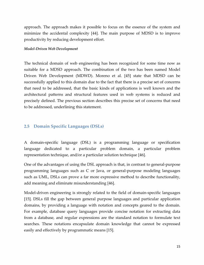
The version of UML 2.4 has 14 types of diagrams divided into two categories [49]. Seven
diagram types represent structural information, and the other seven represent general
types of behavior, including four that represent different aspects of interactions. These
diagrams can be categorized hierarchically as shown in the following class diagram:
17
Figure 3: UML 2.4 Diagrams
2.7 Business Process Model and Notation
Business Process Model and Notation (BPMN) is a graphical representation for
specifying business processes in a business process model [50]. Business Process
Management Initiative (BPMI) developed BPMN, which has been maintained by the
Object Management Group since the two organizations merged in 2005. As of March
2011, the current version of BPMN is 2.0 [50].
Business Process Model and Notation (BPMN) is a standard for business process
modeling that provides a graphical notation for specifying business processes in a
Business Process Diagram (BPD) [51], based on a flowcharting technique very similar to
activity diagrams from Unified Modeling Language (UML) [52]. The objective of BPMN
is to support business process management, for both technical users and business users,
by providing a notation that is intuitive to business users, yet able to represent complex
process semantics.

18
The primary goal of BPMN is to provide a standard notation readily understandable by
all business stakeholders. These include the business analysts who create and refine the
processes, the technical developers responsible for implementing them, and the
business managers who monitor and manage them. Consequently, BPMN serves as a
common language, bridging the communication gap that frequently occurs between
business process design and implementation.
BPMN models consist of simple diagrams constructed from a limited set of graphical
elements. For both business users and developers, they simplify understanding
business activities' flow and process. BPMN's four basic element categories are: flow
objects, connecting objects, swim lanes and artifacts. Flow objects are the main
describing elements within BPMN, and consist of three core elements: Events,
Activities, and Gateways [53]. The Figure 4, shows the graphical representation of the
flow and connecting objects.
Event Activity Gateway Connections
Figure 4: Flow and connecting objects
2.8 Mendix
Mendix is a MDD tool that can be categorized as a MDE application builder. Mendix
makes possible to quickly design, build, test, integrate, deploy, manage and optimize
service-oriented business applications within any existing business and IT environment
without code. It has a collaborative and agile platform for rapidly building and
managing business applications that smoothly integrate with existing systems [46].
The Mendix tool allows building web-based systems by interrelating models of both the
system behavior and structure. The following three main model types are used to build
19
a system using the Mendix business modeler: ‚domain model‛, ‚form-models‛ and
‚microflows‛.
A domain model, an information model depicting the information structure of
the system. The syntax used for these models are a Mendix specific graphical
notation, however the use of UML class diagrams are being considered for a
future release.
Form-models, depicting the system user interface consisting of menus and forms.
Forms are drawn using simple graphical user interface widgets, such as tables,
input fields and buttons.
Microflows, process models depicting special procedural logic that needs to be
executed. The notation used for these models
is based on business process modeling notation (BPMN) and similar to UML
activity diagrams, with a few extensions.
2.8.1 Characteristics
Mendix is put forward as a platform-as-a-service that improves collaboration between
business and IT, increasing long term business agility for organizations of any size or
industry. The platform consists of three products that seamlessly work together to
simplify agile application lifecycle management (ALM) by enabling rapid development,
deployment, and management of enterprise applications in the cloud [46].
According to Mendix [46], it is possible to reduce time-to-market of new applications
and business initiatives by at least 5 times at about ½ the cost, gain instant flexibility to
respond to new insights and changing business requirements when needed and
enhance collaboration between business and IT. Mendix also claims make possible to
easily capture the application design in visual models, create prototypes faster than
other technologies and extend existing systems with agile front-end applications.In
order to investigate what Mendix claims, an empirical study is necessary. In order to
investigate these claims, an empirical study is necessary (this thesis project will
collaborate to this investigation).
Mendix has gained market attention lately and Gartner categorized it as a ‘Cool
Vendor’ in the category ‚Cool Vendors in Application Development, New Tools, 2009″
published on March 30th of same year [46].

20
Architecture
Figure 5 illustrates a top-level view of the technical architecture, showing the
composition of the core components of the Mendix framework. As illustrated, a clear
distinction can be made between a design-time and run-time environment. This consists
of [46]:
An intuitive, multi-user visual modeling studio - Business Modeler - to capture design-
time business requirements and rules
A scalable, high-performance run-time engine for executing model definitions -
Business Server
A state-of-the-art Rich Web Client to deliver a superior and personalized user
experience
A Service Layer for easily exposing and consuming Web services
A Connectivity Manager to integrate external systems, databases and files
Access to a Community, providing reusable business models, plug-ins, custom
widgets and code
Figure 5: Top Level Overview of Mendix Architecture
2.8.2 Competitors
Logically, Mendix has competitors in the industry. Making a research over the Internet
on sites dedicated to technology and organized as blogs, forums, etc.; similar tools were
founded. Three of them were selected based on the following criteria: The tool must be
21
able to create web applications. The tool must be innovative and impactful, taking as a
reference if it has been selected by Gartner as ‘Cool Vendors’. Its popularity and
support are also taken into account measuring it with the Google page rank [54] and its
connection to the university. Furthermore, its global presence is also part of the criteria
as well as it friendliness.
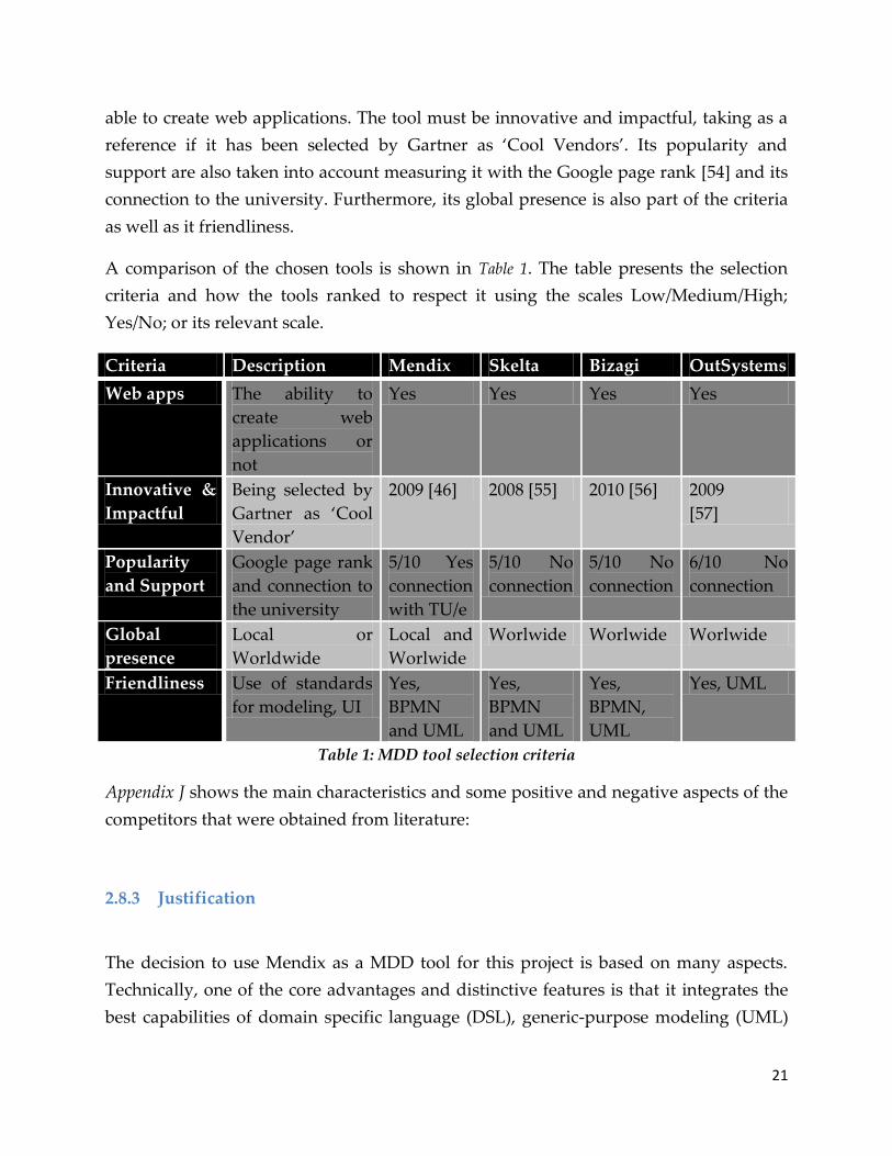
A comparison of the chosen tools is shown in Table 1. The table presents the selection
criteria and how the tools ranked to respect it using the scales Low/Medium/High;
Yes/No; or its relevant scale.
Criteria Description Mendix Skelta Bizagi OutSystems
Web apps The ability to
create web
applications or
not
Yes Yes Yes Yes
Innovative &
Impactful
Being selected by
Gartner as ‘Cool
Vendor’
2009 [46] 2008 [55] 2010 [56] 2009
[57]
Popularity
and Support
Google page rank
and connection to
the university
5/10 Yes
connection
with TU/e
5/10 No
connection
5/10 No
connection
6/10 No
connection
Global
presence
Local or
Worldwide
Local and
Worlwide
Worlwide Worlwide Worlwide
Friendliness Use of standards
for modeling, UI
Yes,
BPMN
and UML
Yes,
BPMN
and UML
Yes,
BPMN,
UML
Yes, UML
Table 1: MDD tool selection criteria
Appendix J shows the main characteristics and some positive and negative aspects of the
competitors that were obtained from literature:
2.8.3 Justification
The decision to use Mendix as a MDD tool for this project is based on many aspects.
Technically, one of the core advantages and distinctive features is that it integrates the
best capabilities of domain specific language (DSL), generic-purpose modeling (UML)

22
and generic-purpose programming (Java, .NET) in a framework and co-exists in an
integrated way. It provides the software tools, methodology and platform architecture
to rapidly model, build, test, integrate, deploy, manage and optimize applications
without code.
Some other aspects influenced the decision. As a dutch company, Mendix has several
connections, partnerships and research collaborations with dutch universities, including
TU/e, this make access to development tool and direct support from the company
experts. Second, as it aims to provide an agile and rapid development, it is a good
opportunity to probe if a MDD tool also can facilitate a good maintainability of the
applications developed over the time. Third, its user friendliness in
combination with industry standards like BPMN and UML make it a good option for
modeling. Fourth, Mendix is recognized as an important vendor from Gartner that
guarantee quality in the product.
2.9 PHP
PHP was started in 1994 by Rasmus Lerdorf and was an acronym standing for Personal
Home Page (replaced in 1997 with PHP: Hypertext Preprocessor). The language is
developed and implemented by The PHP Group nowadays. It is released under terms
of on open source license and documentation is freely available online [58].
PHP is widely used for implementing Web applications, in part due to its rich library
support for network interaction, HTTP processing, and database access. The input to a
PHP program is a map from strings to strings. Each key is a parameter that the program
can read, write, or check if it is set. The string value corresponding to a key may be
interpreted as a numerical value if appropriate. The output of a PHP Web application is
an HTML document that can be presented in a Web browser. PHP is object-oriented, in
the sense that it has classes, interfaces, and dynamically dispatched methods with
syntax and semantics similar to that of Java. PHP also has features of scripting
languages, such as dynamic typing, and an eval construct that interprets and executes a
string value that was computed at run-time as a code fragment [59]. For example, the
following code fragment:

23
$code = "$x = 3;"; $x = 7; eval($code); echo $x;
prints the value 3 (names of PHP variables start with the $ character). Other examples of
the dynamic nature of PHP are a predicate that checks whether a variable has been
defined, and class and function definitions that are statements that may occur
anywhere.
2.9.1 Characteristics
The major characteristics of PHP are the following [60]:
PHP is web-specific and open source.
Scripts are embedded into static HTML files.
Fast execution of scripts.
Fast access to the database tier of applications.
Supported by most web servers and operating systems.
Supports many standard network protocols libraries available for IMAP, NNTP,
SMTP, POP3,
Supports many database management systems libraries available for UNIXDBM,
MySQL, Oracle, Dynamic Output any text, HTML XHTML and any other XML
file.
Also Dynamic Output images, PDF files and even Flash movies
Text processing features, from the POSIX Extended or Perl regular expressions to
parsing XML documents.
A fully featured programming language suitable for complex systems
development
Architecture
The architecture of any PHP application is very simple: an HTTP request goes from a
browser to a server. The server responds by sending an HTML stream back to the
browser.
If the request is for a PHP script, the server will route the file through the PHP
interpreter, which in turn can issue database requests etcetera. To preserve state
between interactions with a browser, PHP can keep session data. This allows for a

24
conversation with a user, for example to fill a shopping cart, reserve an airline ticket, or
similar [61]. Figure 6 shows a big picture of the architecture:
Figure 6: PHP and Server Architecture
2.9.2 Competitors
There are other scripting and web programming languages besides PHP. Some of the
most popular are Perl, ASP, JSP [58] [60] [62]. The main characteristics of each one will
be outlined in the following paragraphs.
Perl
It is one of the longest running and most successful free open-source projects.
Embracing both a programming language and a whole philosophy of usage and design,
Perl has quietly and without much hype, provided a better case-study of extensible and
reusable software design than almost anything that has gone before it. It is very hard to
find a computer system that hasn't some form of support for Perl available. An
astonishing range of free extensions (modules) exist for Perl, by far outweighing the
impact of Perl simply as a vehicle for expressing programs [60] [63].
It presents a more daunting challenge for non-programmers who want to complete
simple tasks with active websites, requiring rather more learning before starting than
say ASP or PHP [62].

25
ASP
Active Server Pages (ASP) is a rounded proprietary product from Microsoft. Although
ASP is really a framework into which various languages can plug, most people consider
it implies using VB Script language (JavaScript can also be used out-of-the-box).
Regrettably, it is only properly supported on Microsoft's IIS platform thus ruling it out
of contention for serious commercial users who care about security and reliability [62].
VB Script is a version of Visual Basic (without the visuals) and with features tailored to
make it suitable for use for building websites on Microsoft platforms. VB Script uses
Active Data Objects and the ODBC (Open Database Connectivity) interface to provide
good database independence [62] [64]. Simple websites are easy to build and there is a
range of supporting tools to help beginners but it is not really cross-platform.
JSP
Java Server Pages are an extension to the Java servlet technology that was developed by
Sun. JSPs have dynamic scripting capability that works in tandem with HTML code,
separating the page logic from the static elements to help make the HTML more
functional [62]. JSPs are translated and compiled into JAVA servlets but are easier to
develop than JAVA servlets. JSPs are not restricted to any specific platform or server. It
was originally created as an alternative to Microsoft's ASPs (Active Server Pages) [65].
Because JSP pages are translated, and then compiled into Java servlets, errors that creep
in the pages are rarely seen as errors arising from the coding of JSP pages. Instead, such
errors are seen as either Java servlet errors or HTML errors [65]. Due to this translation,
the pages are converted into class files and the server has to store them with the JSP
pages, requiring more disk space than PHP for example. This is an issue of compiled
languages versus interpreted languages and not exclusive of JSPs.
2.9.3 Justification
PHP is a popular and well known programming language. One indicator of popularity
is the TIOBE Programming Community Index [66]. It is a programming language
ranking based on skilled engineers, courses, third party vendors and search engine

26
ratings. The website says “The index can be used to check whether your programming skills
are still up to date or to make a strategic decision about what programming language should be
adopted when starting to build a new software system". As of October 2006 PHP was ranked
on the fourth place, Perl in sixth. Java Script was in the ninth position and VB Script is
between the 51st and 100th. In 2004, PHP was selected as the ‚Programming Language of
the Year‛ [66]. PHP is used by the most popular content management systems like
MediaWiki, Drupal, Joomla and WordPress [58]. PHP follows a very classical
approach, is extensively documented and will probably be the most familiar to web
programmers.
To conclude, the main features of PHP that makes it a good programming language for
web developing are [67] [58] [62]:
It is a successful product of the open source initiative which means that there is
community support along with an extensive set of libraries that can be used to
enhance the functionality of the language.
It is easily integrated with several other open source softwares and programs
without requiring any extra plugins or libraries.
It has all the features of OOPS (Object Oriented Programming Languages) as
well procedural languages.
The community support is huge.
There are a lot of free and premium hostings for PHP.
It is free and easy to learn.
27
3 Case Study
In this chapter, the case study that is going to be used is described. This includes the
specification of use cases that will be evaluated and the type of maintenance that is
aimed with the new solution in Mendix. Afterwards, the lifecycle of the project is
explained and exemplified, indicating which methods, techniques or tools were used on
each stage.
3.1 SHARE
SHARE is a platform based on cloud computing for sharing practically any type of case
study solution to reviewers and workshop participants. The system integrates
virtualization and web technologies to provide online access to tool demos. The access
control and messaging features enable that the system is adopted by other workshop
and conference organizers that wish to complement the conventional paper reviewing
process [23].
From a platform perspective, SHARE relies on Apache a web container, MySQL as a
database engine, and VirtualBox as a hypervisor. The web server and the virtual
machine servers run Linux natively. The website is implemented in PHP. The
communication between web and virtual machine servers is realized via Bash cron jobs
[23].
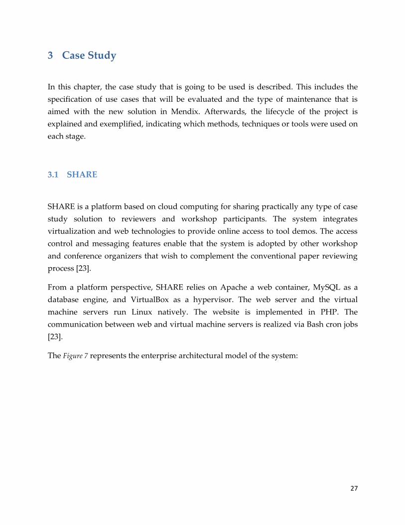
The Figure 7 represents the enterprise architectural model of the system:

28
Figure 7: SHARE Architecture Model
The numbers in the figure represent elements of a typical scenario through the system
that is explained in detail on [23]. The outline of the elements is the following:
1. User authentication on the website
2. Web server
3. Database
4. Interaction to initiate new virtual machine session between the user and the web
server
5. Resulting activity on a virtual machine server (contains selected image, sufficient
amount of processing and memory power available at the selected time interval)
6. Server boots a virtual machine with the selected image and makes it available for
the user
7. User credentials (connectivity remotely to a virtual machine).
The general overview of the scenario starts when a user authenticates to the SHARE
website. The web server uses the information stored in the database to choose with
images the user can use. Then, the virtual machine server boots a virtual machine with
the image selected by the user and makes it available to him. As it can see in Figure 7, the
SHARE servers are displayed symbolically on top of a cloud graphic to represent that
SHARE is an academic cloud [23]. Within the cloud there are two types of servers: web
and virtual machine servers. The web server hosts all dynamic web pages for starting,
cloning and organizing virtual machines. Currently, the web server also hosts the
database.

29
The virtual machine servers are part of different university networks so they are
protected by corporate firewalls [23]. The web server communicates with these
machines via Security Shell (SSH) that is a secure network protocol for data
communication. Additionally, the port to connecting remotely to the virtual machine is
assigned randomly for each session and the Remote Desktop Protocol (RDP) supports
encryption methods [23].
It was decided to choose this platform for the case study of this project because it is an
application coded with PHP, which infrastructure relies on universities (academic
research cloud). In addition, as the Eindhoven University of Technology is part of this
project, it facilitates the access to the source code, database scripts, etc. Furthermore, it is
possible to talk and ask questions in person to the creators of the system for any
possible remark.
3.2 Case study characteristics
SHARE is, in a nutshell, “an online workflow system to: request access to a group of virtual
machine images; start a virtual machine for evaluation purposes; create a virtual machine image
containing your research software and related documentation and publish it to a group” [23].
In addition, the system enables organizers (certain type of users) [23], to manage user
registrations, create new groups and perform some other administrative tasks. The
images can be replicated or migrated across servers by the server administrators.
The Figure 8 shows a use case diagram that models the main original functional
requirements of the system [23]. Use cases related to virtual machines are shown on the
left of the diagram, use cases related to groups (i.e., image access rights) are shown in
the middle, and use cases related to computational resources are shown on the right.

30
Organizer
Manage Groups
Bundle Admin
* * * *
Register for GroupUse remote machine
Create DemoEvaluate Demo
Manage Internet
access
Manage Hardware
LoadRequest Mutable
Clone
Advertize
*
*
*
*
«extends»
Evaluator
**
«extends» «extends»
**
**
Host Admin
*
*
*
*
Demonstrator
Image Owner
Paper Reader PC Member
*
*
*
*
* *
*
*
«subtype»
«subtype»
«subtype» «subtype»
*
*
Figure 8: Use case diagram of original system
A general description of the existent roles for registered users in the system is provided:
Organizer: Administers his own group(s). He is responsible for managing group
access, managing clone requests and advertising the images in the group.
Demonstrator: He is owner of images. He is able to modify certain information of
the image and also can create a demo and publish the image to other users.
Evaluator: Evaluates demos and he is able to register into one or more groups.
Bundle Admin: Add groups to the system
Host Admin: Administers his own server(s). This implies the administration of
the requests for mutable images, registration of new images, sessions of
evaluators and demonstrators in the server and internet access to the users.
The platform has been evolving and within this evolution, the users have demanded for
new functionalities or modification of the existent ones. These features requests have
caused modifications to the system at different levels: logical level, data level, graphical
level. In consequence, maintenance activities have been executed in order to accomplish
the new requirements. Due to the continue evolution of the platform, it is interesting to
know if other type of implementation can provide better results for maintenance that
generate reduction in time, easiness to perform modifications, etc.
31
A set of requirements that have been requested and implemented already in the current
system are grouped in five use cases. These use cases have been selected based on the
areas of maintenance defined in section 2.2.2. The use cases selected and the boundaries
of this study will be exposed in the next sections.
3.2.1 Use cases
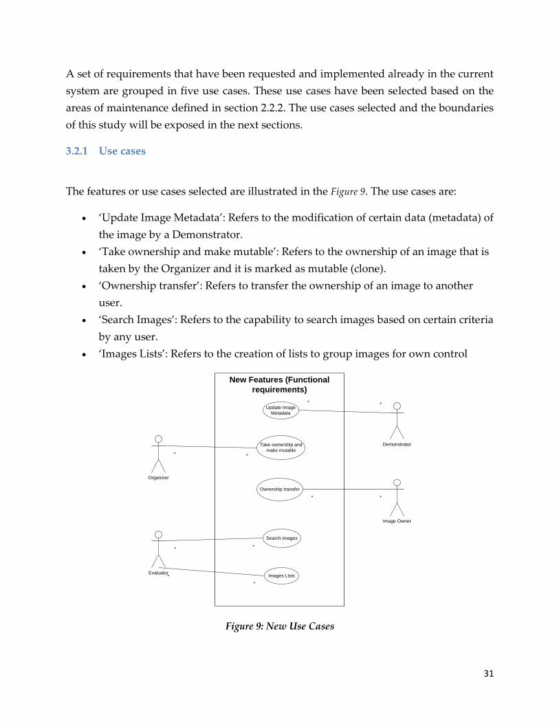
The features or use cases selected are illustrated in the Figure 9. The use cases are:
‘Update Image Metadata’: Refers to the modification of certain data (metadata) of
the image by a Demonstrator.
‘Take ownership and make mutable’: Refers to the ownership of an image that is
taken by the Organizer and it is marked as mutable (clone).
‘Ownership transfer’: Refers to transfer the ownership of an image to another
user.
‘Search Images’: Refers to the capability to search images based on certain criteria
by any user.
‘Images Lists’: Refers to the creation of lists to group images for own control
Search images
Images Lists
Ownership transfer
Take ownership and
make mutable
Update Image
Metadata
New Features (Functional
requirements)
Organizer
Evaluator
Demonstrator
Image Owner
* *
* *
**
**
*
*
Figure 9: New Use Cases

32
These cases were selected because they represent most of the main modifications or
additions that the users of the system have requested. These new requirements implied
to modify, extend or create elements and rules in the database, the user interface and
even in the behavior of the system. The use cases are explained in detail the Appendix A.
Referring to the classification of maintenance on section 2.2.2, the features selected are
distributed in two of the three areas of maintenance: adaptive and perfective. All of
these medications were requested, accepted and implemented in order to provide or
extend functionality that already existed but could be improved or that didn’t exist. No
one refers to correction in hardware or software.
3.2.2 Boundaries
The limitations of the project are:
For the use case of ‘Images Lists’, it is not going to provide an RSS feed as it is
implemented in the current system due to the lack of knowledge of the tool and
the time available to research more about it.
From the architectural point of view, the current solution uses two types of
servers to provide the desired functionality over the cloud: a web server and a
set of virtual machine servers. The study is not going to modify anything related
with the virtual machine servers including the communication with the web that
is realized via Bash cron jobs. Due to the limitation of time and lack of
knowledge, the behavior of the virtual machine servers will be simulated with
scheduled events that are part of the functionality provided by the MDD tool.
These events will update the database in order to imitate the current behavior of
the system.
The current code based solution and the model-driven solution will not be
working on real servers. Instead, they will run over virtual machines contained
in one host (PC) localized inside the university, that will act as a server and could
be accessed externally.

33
3.3 Execution
In order to accomplish this study, it is necessary to follow a methodology to construct
the new system with a MDD tool and compare it with the original solution. The
concepts mentioned by Demeyer, et al. [68] for object-oriented reengineering patterns as
a general methodology, in combination with the AMDD (Agile Model-Driven
Development) defined by Ambler [69], will be used as base techniques for the
development of the new platform.
The reasons to choose these methods are that they provide guidelines that fit with the
purposes of the project and are aligned to the development methodology that Mendix
uses for development.
There are three key concepts in the reengineering lifecycle that are mentioned in the
same context and are confused sometimes. These concepts are reverse engineering,
reengineering and forward engineering. Chikofsky and Cross [70] define these terms as
follows:
“Reverse Engineering is the process of analyzing a subject sys- tem to identify the
system’s components and their interrelationships and create representations of the
system in another form or at a higher level of abstraction.”
That is to say, reverse engineering is essentially concerned with trying to ‚understand‛
a system and how it ticks.
“Reengineering ... is the examination and alteration of a subject system to
reconstitute it in a new form and the subsequent implementation of the new form.”
Reengineering, on the other hand, is concerned with ‚restructuring‛ a system, generally
to fix some real or perceived problems, but more specifically in preparation for further
development and extension.
Finally, we have forward engineering as following:
“Forward Engineering is the traditional process of moving from high-level
abstractions and logical, implementation-independent designs to the physical
implementation of a system.”
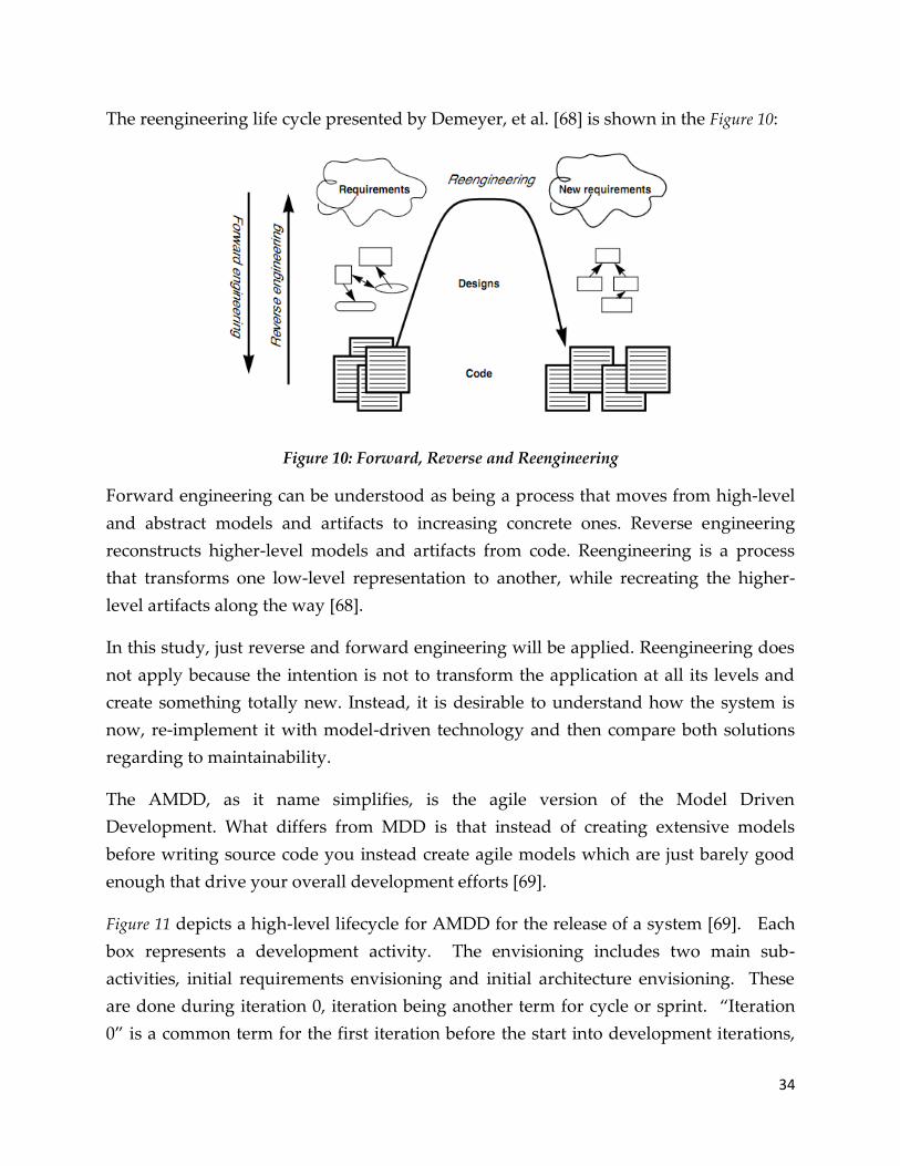
34
The reengineering life cycle presented by Demeyer, et al. [68] is shown in the Figure 10:
Figure 10: Forward, Reverse and Reengineering
Forward engineering can be understood as being a process that moves from high-level
and abstract models and artifacts to increasing concrete ones. Reverse engineering
reconstructs higher-level models and artifacts from code. Reengineering is a process
that transforms one low-level representation to another, while recreating the higher-
level artifacts along the way [68].
In this study, just reverse and forward engineering will be applied. Reengineering does
not apply because the intention is not to transform the application at all its levels and
create something totally new. Instead, it is desirable to understand how the system is
now, re-implement it with model-driven technology and then compare both solutions
regarding to maintainability.
The AMDD, as it name simplifies, is the agile version of the Model Driven
Development. What differs from MDD is that instead of creating extensive models
before writing source code you instead create agile models which are just barely good
enough that drive your overall development efforts [69].
Figure 11 depicts a high-level lifecycle for AMDD for the release of a system [69]. Each
box represents a development activity. The envisioning includes two main sub-
activities, initial requirements envisioning and initial architecture envisioning. These
are done during iteration 0, iteration being another term for cycle or sprint. ‚Iteration
0‛ is a common term for the first iteration before the start into development iterations,
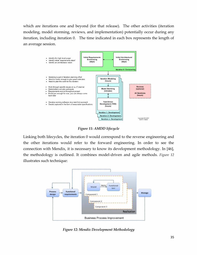
35
which are iterations one and beyond (for that release). The other activities (iteration
modeling, model storming, reviews, and implementation) potentially occur during any
iteration, including iteration 0. The time indicated in each box represents the length of
an average session.
Figure 11: AMDD lifecycle
Linking both lifecycles, the iteration 0 would correspond to the reverse engineering and
the other iterations would refer to the forward engineering. In order to see the
connection with Mendix, it is necessary to know its development methodology. In [46],
the methodology is outlined. It combines model-driven and agile methods. Figure 12
illustrates such technique:
Figure 12: Mendix Development Methodology

36
The first step is to design the processes that have to be automated. These process
designs are not directly executable within the Mendix methodology. They are used to
specify requirements and documentation (reverse engineering) and as a reference guide
for developing the components based on models (forward engineering). In practice,
more and more information becomes available as time goes by, which makes it
necessary to develop in a highly iterative manner.
In the following sub-sections it is going to be explained which activities were performed
on each of both engineering techniques for the development of the re-solution,
including the specific activities performed with the Mendix tool (Mendix Business
Modeler).
3.3.1 Reverse Engineering
As it was stated in the last section, the purpose of the reverse engineering is to
understand how something really works. For this project, it is important to know the
functionality and organization of the system that includes the structure of the database;
the architecture of the application; the exceptions and business rules, the navigation
within the application, etc.
During this project, it was necessary to read and analyze the code, analyze the structure
of the database, obtain and analyze the relations between the web pages and ask to the
experts.
It is important to remark that the first analysis of the entire system was executed over a
previous version of it (without any of the new features selected for the comparison).
The reason for this is that by the time the project was initialized, most of those ‘new’
requirements had not been implemented. Iterations over this analysis were
subsequently performed in order to know and understand the modifications that
occurred in the original solution for the new functionalities.
For the analysis of the code and the database, no tool or method was selected. The
source files of PHP were read and notes about the validations, exceptions, data flow
and security were taken.
During this code analysis, the links between screens were also identified. In order to
have an outline how each screen is linked to the others, screenflow diagrams were

37
created. The diagrams help to outline how each screen in user interface links to the
others [71] and identify the graphical elements that are important to navigate through
the application, including those related with the modification and search of data
(information). The Appendix shows the screenflow diagram for the base version of the
system. The main elements of these diagrams are:
Box: Is a screen (page) and the elements inside are buttons, links, text fields, text
areas, combo boxes, radio buttons or some other specific field (i.e. text).
Solid arrow: Represents an action that is performed by the user (i.e. click a button
or a link) or by the web page (i.e. store info into the database)
Dotted arrow: Is used to indicate that a page is included and then it represents
another piece of information.
Open rectangles: Comments to clarify the functionality or just to provide a little
more detail about what happens with that action (button or link click).
The database was analyzed reading the scripts to create it and also looking at the tables
and the flow of information through the web pages. As a result, an initial Entity-
Relationship Diagram was created to have an overview of the tables that existed and
their relationship. Appendix shows the diagram.
The questions to the experts were to clarify certain validations and rules that occurred
within the analysis of the system. This included some actions that take place between
the web server and the virtual machine server with the cron jobs.
The result of these activities generated the Domain Model in Mendix and settled the
basis for the forms, microflows and security for the model driven development that will
be described in the next section.
3.3.2 Forward Engineering
In this section, the actions corresponding to the forward engineering process for the
model-driven solution are going to be illustrated. The actions are executed on each of
the model types used to build a system using the Business Modeler.

38
3.3.2.1 Domain Model
The first activity was to define the information or data structure that the system should
handle. This was covered creating the initial Domain Model in Mendix with the
Business Modeler (Figure 13). The model is an abstract model (data model), based on
reflection of reality. This model can be used to set rights on CRUD (create, read, update,
delete) operations.
Figure 13: Initial Domain Model
As shown in the figure, Mendix uses a notation similar to the UML class diagram. For
example, we have the entities (objects) ‘VDI ‘and ‘Host’. A Host may contain zero or
many VDIs but a VDI is stored in just one Host. In addition, the arrow indicates that the
association is recorded in the VDI.
In addition to allowing the specification of objects, their attributes and associations; the
model also allows the designer to specify how the model should behave at run-time.
Validation rules can be set on attributes, stating that they are mandatory, or giving a
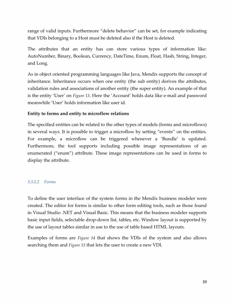
39
range of valid inputs. Furthermore ‚delete behavior‛ can be set, for example indicating
that VDIs belonging to a Host must be deleted also if the Host is deleted.
The attributes that an entity has can store various types of information like:
AutoNumber, Binary, Boolean, Currency, DateTime, Enum, Float, Hash, String, Integer,
and Long.
As in object oriented programming languages like Java, Mendix supports the concept of
inheritance. Inheritance occurs when one entity (the sub entity) derives the attributes,
validation rules and associations of another entity (the super entity). An example of that
is the entity ‘User’ on Figure 13. Here the ‘Account’ holds data like e-mail and password
meanwhile ‘User’ holds information like user id.
Entity to forms and entity to microflow relations
The specified entities can be related to the other types of models (forms and microflows)
in several ways. It is possible to trigger a microflow by setting ‚events‛ on the entities.
For example, a microflow can be triggered whenever a ‘Bundle’ is updated.
Furthermore, the tool supports including possible image representations of an
enumerated (‚enum‛) attribute. These image representations can be used in forms to
display the attribute.
3.3.2.2 Forms
To define the user interface of the system forms in the Mendix business modeler were
created. The editor for forms is similar to other form editing tools, such as those found
in Visual Studio .NET and Visual Basic. This means that the business modeler supports
basic input fields, selectable drop-down list, tables, etc. Window layout is supported by
the use of layout tables similar in use to the use of table based HTML layouts.
Examples of forms are Figure 14 that shows the VDIs of the system and also allows
searching them and Figure 15 that lets the user to create a new VDI.
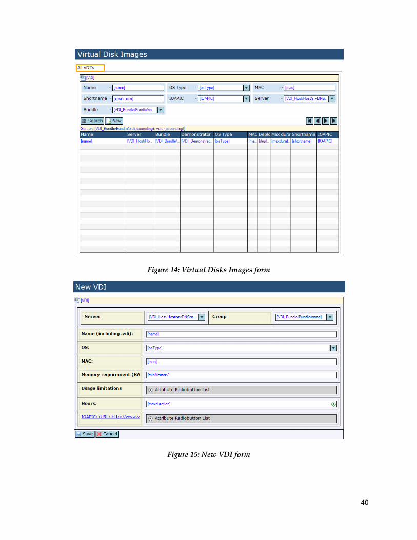
40
Figure 14: Virtual Disks Images form
Figure 15: New VDI form

41
Form-to-entity relations
In order to populate the form with information in run-time, the created forms need to
be related to the domain model. A simple relation is to connect a field to an attribute in
one of the entities of the domain model. A more interesting relation between the forms
and the entities is how the mapping between associations and forms is done. As can be
seen in Figure 16, a single form can be mapped to several entities, in this case Bundle and
VDI. In order to indicate that only the VDIs belonging to a certain Bundle should be
displayed, the VDI table is put inside the Bundle sub-form. This Bundle sub-form
listens to the sub-form located above where the Bundle can be chosen. This indicates
that when interpreting the model and executing a database query the business server
should use the association between the Bundle and VDI to find the relevant VDIs and
displays these in the lower Bundle sub-form. If the VDI table was to be put outside the
Bundle sub-form, all VDIs would have been displayed.
Figure 16: Update Virtual Disk Image

42
Form-to-form relations
A form can also be related to other forms. For example, the ‘New’ button on Virtual
Disks Images Form (Figure 14), can be connected to New VDI form (Figure 15). In fact, if
there is no connection between the ‘New’ button and a form, an error will be shown in
the error list of the modeler (Figure 17).
Figure 17: Errors in error list
Form-to-microflow relations
Just as events in the domain model can trigger microflows, events in the forms can also
be made to start microflows. For example, it is possible to add a button to a form and
connect that to a microflow. The microflow can change objects (entities) and these
changes can be displayed instantly in the user interface. The simple user-interface logic,
can be done without the use of microflow. However, for specific logic, such as
displaying different forms depending on the entered data or role, microflows give full
control over the user interface. An example microflow will be shown in the next section.
3.3.2.3 Microflows
Microflows were used to define complex logic in system built using Mendix. As
mentioned previously, microflows can be triggered by events in both the domain model
and in forms allowing the designer to extend the behavior of the system beyond what
can be done using the forms and domain model. By using a microflow, the designer can
change objects (entities), and control how and when forms are displayed. Microflows
also are a source for integration with external systems using web-services. The types of
constructs that can be used in a microflow are: events, (looped) activities, gateways,

43
connecting objects and artifacts. The Appendix E contains a table per each type of
construct, showing their names, their representation and a small explanation about their
specific function. A general explanation of each type will be provided in the next
subsection.
Types of constructs
EVENTS
The most common events are circles in either green or red, which represent the start
and end of a microflow. The start event can only occur once per microflow, the end
event can occur multiple times.
ACTIVITIES
Activities are blue squares in a microflow, which can have various types. The possible
types are action calls, object actions, variable actions and client activities.
GATEWAYS
Gateways are diamond shaped objects within the microflow that indicate splits and
joins of the process.
CONNECTING OBJECTS
There are only two types of connecting objects in Mendix, being the sequence flow and
an association. Basically the first indicates the flow between actions, while the second is
merely a means to connect comment annotations to other elements.
ARTIFACTS
Artifacts consist out of input data objects and annotations.
Microflow example
An example of a microflow used in the project is displayed on Figure 18. It is used to
approve a mutable disk request (create a clone of a VDI). It receives a ‘VDI’ as a
parameter and then it is checked with an exclusive split if the owner of the VDI
approved the request. If it is the case, the ‘ownerApproval’ attribute of the VDI is
modified and a message is shown indicating this; otherwise, it jumps directly to retrieve

44
the ‘Bundle’ of the VDI that also occurs if the VDI was approved by the owner.
Afterwards, it is verified if the organizer of the Bundle approved the request and the
same process is repeated but now for the attribute ‘adminApproval’ of the VDI.
Figure 18: Approve Mutable Disk Request microflow
This microflow is very simple, however the editor also allows expressing significantly
more complex application logic by the use of loops, calling other microflows, opening
forms, etc. Microflows can also call custom made Java code and external web services.
To trigger the start of the microflow we need to connect it to an event, either in the
forms or in the objects. For this example the microflow is triggered when a request is
approved by the owner of the VDI or the organizer of the VDI’s group. To do this, the
property ‘On click’ of a microflow trigger (that can be seen as a hyperlink) is modified
to execute this microflow if the link is clicked.
Microflow-to-forms relations
As stated before, microflows can be triggered by buttons or controls in the forms.
However a microflow can also be used to coordinate the usage of forms. For example, it
is possible to define a sequence of forms by the use of microflows.
Microflows-to-model relations
Events in the domain model, such as storing an object or changing it, can be made to
trigger microflows. s can also work in the other direction: they can be used to
manipulate objects. The full range of CRUD operations (Create-Read-Update-Delete) is
supported.

45
3.3.2.4 Security, running the system and remarks
Security
Security in Mendix has two sides: different people must be able to see different parts of
the application and it is desired to prevent unauthorized access. Both of these can be
managed from the Business Modeler. Access to forms, data and microflow can be
limited to authorized users with the security DSL. It allows different people to see
different forms and data, prevents unauthorized people from meddling with the system
and provides a role-based access control [46]. Figure 19 shows an example of how to
configure the Entity access on Mendix.
Figure 19: Configuring security in Mendix

46
Running the system
When the models are ready in the business modeler, they can be deployed to the
business server. At this stage the models are transferred to the model repository, and a
database is created based on the domain model. When the model has been deployed
and the business server is started the system can be accessed via a web-browser. Figure
20 shows the Home page form running in the browser. The server generates HTML,
CSS and JavaScript, thus, there is no need to install any extra plug-ins in the browser.
Figure 20: Home page running in a browser
Remarks
After some iteration, the system was completed. The domain model was changing and
the final version is on the Appendix F. Also, the screenflows for the new features were
created (Appendix G).
47
3.4 Comparison
The testing of the application was executed at the end of each iteration that was
performed during the development process. After testing, it is necessary to compare
both solutions and define which approach is more suitable for the maintenance of such
system.
For this, a new framework was designed in order to compare a based code solution
versus a model driven solution. It was designed taking in account that Mendix does not
generate code and the PHP system was purely coded. But the intention of this
framework was also to make it applicable for other solutions. In the next chapter, it is
going to be described how the framework was created.

48
4 Comparison Framework
To have a complete comparison between the two development approaches under
investigation in this thesis, a new comparison framework is developed. First, the
motivation of the framework is stated. In section 4.2 the four levels that the comparison
includes are described. Section 4.3 refers to the definition of the framework.
4.1 Reason
The main reason to create a new framework to evaluate the code based implementation
and model driven implementation in terms of maintainability is because there is a lack
of such kind of frameworks.
There exist other studies that compare model-driven technologies but either not in term
of maintainability or against coded-based implementations. One of them is exposed by
Grozev [72], which is about general comparisons between component-based software
engineering and model-driven engineering in order to obtain differences and
similarities between them. Özgür [73] executes a comparison of Microsoft DSL Tools
and Eclipse Modeling Frameworks but it is just focused in the advantages and
disadvantages of both technologies for the development of Domain-Specific Languages.
Finally, there is a case study presented by Krogman [74] that compares functional
identical software developed in a code-centric conventional style and once using
Eclipse-based model-driven tools. But this comparison is mainly focused on quality,
efficiency and time effort. Additionally, the comparison applies only to the narrow
domain of graphical editors for software models.
In the next section, the new proposed framework will be defined.

49
4.2 Definition of framework
The approaches are classified on four levels: conceptual, design, language and tool [75]
to provide a full comparison between the development techniques. The conceptual level
describes the applications used for the case study of this project. It also verifies that the
code-based and the new model-driven solutions are both responsible for the same set of
features assuring completeness and correctness. The design level refers to the decisions
that affect applications and that are taken by the designer or developer of the
application. For this project the aim is to check if both designs are comparable. The
language level can be seen as the underlying language on which the tool relies on. In
this case, the purpose is to check the understandability of both languages oriented to
maintainability. The tool level describes the properties and limitations of the tool that is
used to build the application.
This classification is required to compare the correct aspects in the correct context. For
example, the model in the model-driven solution can be used to be compared at design
level with the code-based solution but also at language level due to the absence of code
in this specific case.
4.2.1 Conceptual classification
The purpose of this section is to check and compare if the solutions are responsible for
the same conceptual tasks [75]. At the same time, the completeness and correctness of
the solutions must be verified.
First, it is necessary to select the features that are performed on each solution. These
features are documented using use cases. A use case is a description of steps or actions
between a user ("actor") and a software system which leads the user towards something
useful [76]. The use cases are used in system analysis to identify, clarify, and organize
system requirements. A template to document the use case is in the Appendix A.
Selecting and documenting the features make possible to check the completeness of the
solutions.
The correctness of the solutions must be verified also. This can be done demonstrating
that a use case can be executed as it is described using the corresponding solution. In
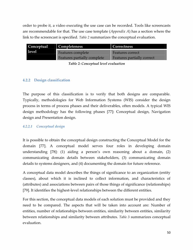
50
order to probe it, a video executing the use case can be recorded. Tools like screencasts
are recommendable for that. The use case template (Appendix A) has a section where the
link to the screencast is specified. Table 2 summarizes the conceptual evaluation.
Conceptual
level
Completeness Correctness
Features complete
Features partially complete
Features correct
Features partially correct
Table 2: Conceptual level evaluation
4.2.2 Design classification
The purpose of this classification is to verify that both designs are comparable.
Typically, methodologies for Web Information Systems (WIS) consider the design
process in terms of process phases and their deliverables, often models. A typical WIS
design methodology has the following phases [77]: Conceptual design, Navigation
design and Presentation design.
4.2.2.1 Conceptual design
It is possible to obtain the conceptual design constructing the Conceptual Model for the
domain [77]. A conceptual model serves four roles in developing domain
understanding [78]: (1) aiding a person’s own reasoning about a domain, (2)
communicating domain details between stakeholders, (3) communicating domain
details to systems designers, and (4) documenting the domain for future reference.
A conceptual data model describes the things of significance to an organization (entity
classes), about which it is inclined to collect information, and characteristics of
(attributes) and associations between pairs of those things of significance (relationships)
[79]. It identifies the highest-level relationships between the different entities.
For this section, the conceptual data models of each solution must be provided and they
need to be compared. The aspects that will be taken into account are: Number of
entities, number of relationships between entities, similarity between entities, similarity
between relationships and similarity between attributes. Table 3 summarizes conceptual
evaluation.

51
Solution 1 Solution 2
Number of entities # #
Number of relationships # #
Similarity between entities Similar, partly similar, dissimilar
Similarity between
relationships
Similar, partly similar, dissimilar
Similarity between attributes Similar, partly similar, dissimilar
Table 3: Conceptual design comparison
The similarity between entities is based on the structure of the entities, number of
entities, objects that they represent. For the relationships it is the same; the number of
relationships between the entities, their purpose or function. In the case of the attributes
their type is important and their function also (affect the similarity of the entities
directly).
4.2.2.2 Navigation and presentation design
As the previous section, the navigation and presentation design can be obtained
building the navigation and presentation models [77]. For this purpose, the use and
creation of screenflow diagrams is proposed as a technique to obtain both designs.
In the section 3.3.1 the screenflows were used during the process of reverse engineering
to obtain and understand the navigation of the application and also to identify the
graphical elements that are important to navigate through it including those related
with the modification and search of data (information). Then, with this type of
diagrams is possible to obtain the navigation design of the system and the presentation
design also because the main graphical controls are already identified within such
screenflows. It is important to clarify that the purpose of the presentation design is not
to compare the graphical interface between solutions but the information presented and
controls needed to navigate through the system.
The diagrams of each solution must be compared. Their similarity will be based on the
number of nodes (screens), the number of arcs (links), number of different nodes and
number of shared nodes. Analyzing these diagrams, it is also possible to check the

52
information and graphical controls on each screen and decide if the presentation is
similar according to these elements.
Table 4 summarizes the navigation and presentation evaluation
Solution 1 Solution 2
Navigation design Similar, partly similar, dissimilar
Presentation design Similar, partly similar, dissimilar
Table 4: Navigation and Presentation comparison
4.2.3 Language classification
In this section, the purpose is to compare both solutions in those properties that rely
directly on the language used to build each of them. Unlike other maintainability
evaluations that rely on direct analysis of source code [80], a comparison between
model-driven and conventional development has to focus on more abstract metrics.
Maintenance operations on models versus maintenance operations on source code
cannot be compared by metrics that are based on the source code [17]. In a model-
driven development environment a maintenance task will mostly be solved by
changing either the application model or in some cases by changing the generator. On
the other hand changes in non-model-driven environments are performed by changing
the source code directly. In the model-driven environment the code is being generated
or no code is generated at all, therefore the code complexity does not influence the
maintainability. Hence metrics such as code complexity cannot be reasonably applied
here.
A solution that facilitates this comparison is to define empirical metrics. But one of the
goals of this project is to make a framework applicable to other solutions, so the
definition of this type of metrics is not an option. The major disadvantage of these
metrics is that they are consequently only valid in the narrow domain for which they
where defined [17]. Instead, it is possible to define meaningful metrics for
maintainability with the GQM (Goal/Question/Metric) approach.
Before the definition of metrics, it is important to know and define the factors that affect
the maintainability and the criteria that can be used to evaluate such factors at language

53
level. According to Bohem et al. [27] there are certain factors that influence
maintainability that are related with the ability to perform maintenance: testability,
understandability and modifiability.
Testability is the extent to which a software product facilitates the establishment of
acceptance criteria and supports evaluation of its performance; understandability is the
extent to which the purpose of a software product is clear to human observer; and
modifiability is the extent to which a software product facilitates the incorporation of
changes [81].
Frapier et al. [82] purpose a criteria to be measured for the evaluation and monitoring
maintainability at every phase of lifecycle. A criterion should be as objective as possible
and easily measurable. For this study and the language classification, the criteria
selected are:
Control structure: determined by conditional statements
Consistency: the extent to which the source code contains uniform notation,
terminology, and symbology within itself
Size: The count of lexical elements, graphical elements, etc.
Table 5 shows the relationships between criteria and factors:
Factor\
Criterion
Understandability Testability Modifiability
Control
structure
X
X
X
Consistency X
Size X X X
Table 5: Relationship between factors and criteria for maintainability
There are more criteria but that is not applicable in this study like independence
(portability of code) or documentation accuracy (documentation of functionality
implemented).

54
4.2.3.1 GQM
The GQM approach is a systematic method to find and define tailored metrics for a
particular environment. In contrast to the collection of metrics that are chosen just
because they can be measured, the GQM approach helps to identify the reasons why
particular metrics are chosen. It also helps to interpret the values resulting from the
collection of these metrics [17]. It provides a mechanism for specifying measurement
goals and refining them into a set of quantifiable questions and metrics in a tractable
way [83].
Goals are defined in order to focus the work to be done and define the framework for
determining whether or not the process or product has the desired qualities. Each goal
must specify the object and purpose of measurement, the issue and the perspective of
measurement [17] [83].
The next step is to define questions that will, when answered, provide information that
will help to find a solution to the goal. Finally, metrics are derived to describe what
data might be collected to answer the questions [17].
GQM is wide used by manager and practitioners because since they have little time to
measure everything, this approach allows them to choose those measures that relate to
the most important goals or the most pressing problems [84].
Please note that for the comparison on this classification, the factors testability and
modifiability which were previously defined in section 4.2.3, are not going to be taken
into account. The reason is that both factors were not executed during the construction
of the model-driven solution. No testability plan was designed or followed and neither
the selected features were implemented separately over a base system (the entire system
was built in a once). These factors could apply for the PHP solution but the purpose
here is to compare both solutions at language level with the same factors and criteria.
To measure the maintainability of both implementations at language level, the
measurement goal was defined according to the GQM method as follows:
Purpose: Comparison
Object: Language
Issue: Understandability

55
Perspective: Developer (development team) or maintainer
GOAL: Determine the level of understandability on each solution from the point of
view of the developer in order to perform maintenance
The following questions were elaborated to cover the goal:
How big is the initial effort to understand the language (technology)?
o Metrics: Number of languages involved in the technology, amount of time
(person-days) to understand the language(s)
How big is the effort to modify or extend the functionality of the system
(implementation of new features)?
o Metrics: Time (person-days) to implement the new parts, time (hours)
spent for testing and debugging, amount of elements (model,
graphical,code) that need to be touched (created, modified, used).
For this project it is not possible to measure the time because it is not possible to know
the time spent to implement the new parts or to learn the language on the code-based
solution because it was already developed when the model-driven was initiated and
that information cannot be obtained. The metrics purposed will be quantitative: the
number of languages involved and the amount of elements that need to be touched.
Now the questions are: how to obtain these metrics from two different approaches?
Which elements must be considered in each of the approaches? How can we compare
models versus code? On the one hand, the code-based solution for this study utilizes
three languages: HTML, SQL and PHP; on the other, the model-driven solution
manages DSLs: Forms, Domain Model, Microflows. Hence, we obtain one of the metrics
trivially but the amount of elements is still missing.
For the code-based solution there are just textual languages classified as a combination
of general purpose languages (PHP) and domain specific languages (HTML, SQL). In
the model driven solution there are modeling languages classified as DSLs. A solution
to compare the languages from both solutions is the use of Model-View-Controller
software architecture [85]. It is a design pattern that structures an application into
different component parts.
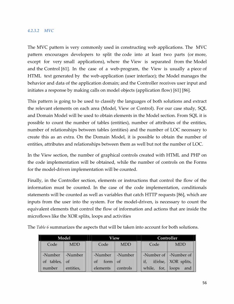
56
4.2.3.2 MVC
The MVC pattern is very commonly used in constructing web applications. The MVC
pattern encourages developers to split the code into at least two parts (or more,
except for very small applications), where the View is separated from the Model
and the Control [61]. In the case of a web-program, the View is usually a piece of
HTML text generated by the web-application (user interface); the Model manages the
behavior and data of the application domain; and the Controller receives user input and
initiates a response by making calls on model objects (application flow) [61] [86].
This pattern is going to be used to classify the languages of both solutions and extract
the relevant elements on each area (Model, View or Control). For our case study, SQL
and Domain Model will be used to obtain elements in the Model section. From SQL it is
possible to count the number of tables (entities), number of attributes of the entities,
number of relationships between tables (entities) and the number of LOC necessary to
create this as an extra. On the Domain Model, it is possible to obtain the number of
entities, attributes and relationships between them as well but not the number of LOC.
In the View section, the number of graphical controls created with HTML and PHP on
the code implementation will be obtained, while the number of controls on the Forms
for the model-driven implementation will be counted.
Finally, in the Controller section, elements or instructions that control the flow of the
information must be counted. In the case of the code implementation, conditionals
statements will be counted as well as variables that catch HTTP requests [86], which are
inputs from the user into the system. For the model-driven, is necessary to count the
equivalent elements that control the flow of information and actions that are inside the
microflows like the XOR splits, loops and activities
The Table 6 summarizes the aspects that will be taken into account for both solutions.
Model View Controller
Code MDD
-Number
of tables,
number
-Number
of
entities,
Code MDD
-Number
of form
elements
-Number
of
controls
Code MDD
-Number of
if, if/else,
while, for,
-Number of
XOR splits,
loops and

57
of
attributes,
number
of
relations
between
tables.
-Number
of LOC
(SQL)
attributes
and
relations
between
entities.
(buttons,
text
fields,
etc.)
in the
form
(data
grids,
buttons,
etc.)
switch
instructions
-Number of
$_GET,
$_POST
activities
(call
microflows,
object
activities)
Table 6: MVC comparison
The comparison will be executed per use case. The numbers obtained must be
combined with the criteria of Table 5 as follows. The Size is affected directly in all the in
the three areas. A big size of elements, reduce the understandability because it makes
more complicated to understand the modifications. In order to know if the size was
negative (-), positive (+) or neutral (+/-) for each implementation, an average number of
elements must be calculated adding the result of the code solution to the result of the
model-driven and dividing it by two. The result of each implementation will be
classified as negative if it is greater than the average; positive if it is lower and neutral if
it is equal or almost equal (the difference cannot exceed one for this).
The Control structure is only affected by the Controller area and the classification is
calculated on the same manner than the Size classification but just taking into account
the numbers of the Controller area.
The Consistency must be evaluated empirically taking into account the Size, the Control
structure and also the degree of simplicity (easy, normal and difficult) in obtaining the
numbers on each area (MVC).
An example of the results can be visualized in the Table 7:

58
Control
structure
Consistency Size
Code Model + -
View + +
Controller - + -
MDD Model + +
View + -
Controller + - -
Table 7: Summarized results of criteria by area
From Table 7 is possible to conclude the level of understandability. In the example of the
table for the code solution, the control structure is negative, consistency is positive also
and the size is negative. Therefore, the conclusion is that the level of understandability
is medium of the code solution (two negative criteria and a positive criterion). The same
procedure occurs with the MDD solution that in the example ends with a medium level
of understandability (two positive criteria and a negative criterion)
4.2.4 Tool classification
The purpose of this section is to create a table to evaluate both implementations from
the tool perspective. In order to do that, certain characteristics from IDE’s for PHP will
be selected as well as characteristics for the evaluation of model-driven tools. The
selection of these characteristics will depend of their relevance and extent of
application.
4.2.4.1 Code based tools
First of all, it is necessary to define what an IDE is. Herrington [87] mentions that an
IDE (Integrated Development Environment) ‚provides a one-stop shop for your coding
work. An IDE contains an editor in which you can edit the code, debug the code, view your code
in a browser (often embedded), and check in and out of source code control. To support that
59
functionality, an IDE has a set of features you do not find in a basic editor, such as Notepad or
Vim. Again, you can extend editors to do a lot of these things, but IDEs have all this
functionality in one tidy package -- typically preconfigured”.
In the case of PHP there are many IDEs in the market but for the purposes of this study,
just four have been chosen to compare them against the model driven tool (Mendix) in
section 4.2.4.3. The IDEs are PHPEclipse, Komodo, PhpED, PHPEdit.
From these IDEs we have selected certain features that are relevant in most of the IDEs
for PHP [87] [88]:
Syntax highlight: Good syntax highlighting improves code readability a lot.
Syntax checking (errors and warnings): On-the-fly syntax checking can prevent
various typos and common programming mistakes.
Debugging: For complex applications in which it is needed to add echo after each
line to see what is going on, debugging can save hours. It's a healthy alternative
to sprinkling echo statements through your code to check values or using the
error log to get the values of variables.
Navigation: Some good IDEs can help with ‚GoTo‛ actions, like go to definition.
This feature also includes searching, that should not take a long time, even with
large projects.
Versioning system: It is extremely useful for both team and one-person
development. It shows what changes have been made to a file, when they were
made and by whom. A good IDE allows you to visually compare revisions, copy
changes from one version to another, revert to previous states and merge
changes made by different team members.
Multiple language support: Refers to the support of not just PHP but a collection
of the related languages: JavaScript, Structured Query Language (SQL),
Hypertext Markup Language (HTML), and Cascading Style Sheets (CSS).
Support for HTML and CSS are often the best, because it's simpler.
Maturity: Refers to the user interface friendliness, the documentation of the
application and the support (mostly online).

60
4.2.4.2 Model driven tools
The features that were selected to create the evaluation table come from the comparison
executed by Kapteijns et al. [89], which evaluates a model-driven framework (XuWare)
with code-based frameworks to generate applications, the aspects suggested by Leuen
[90] and the characteristics of Mendix itself [46].
The features selected are:
Reusability: Unstructured and structured reuse. The unstructured reuse is that
the tool can be used to browse, cut and paste elements. Structured reuse refers to
the support of activities such as definition of reusable components, patterns and
best practices, as well as searching, retrieving and tailoring them.
Manual coding: The possibility to add code manually into the application.
Model type: Refers to the type of modeling that the tool uses. The options can be
UML, DSL, database, none
Observability (debugging): Report errors to the developers in similar way
compilers and debuggers do.
Collaborative development support: The tool provides functionality for
similarity checking and model merging.
Model transformation and refinement support: Support for refinements of
models and definition of refinements in the form of model transformations
between model levels.
4.2.4.3 Table for evaluation
The table to evaluate or compare the solutions at tool level was created taking into
account the features of both approaches. In some cases, certain features do not apply to
both approaches and some other features are merged in common ones.
Code based tool Model-driven tool
Syntax highlight (Y/N)
Syntax checking (Y/N)
Debugging (Y/N)

61
Navigation (Y/N)
Versioning system (Y/N)
Multiple language support
(Y/N)
Maturity (High, Medium,
Low)
Reusability (Y/N)
Manual coding (Y/N)
Model type (UML, DSL,
database, none)
Model transformation and
refinement support (Y/N)
Table 8: Table for tool evaluation
4.3 New framework
The highlight of the new framework is displayed in the Table 9. It consists in four
sections: Conceptual, Design, Language and Tool. A detailed description of the
activities per classification has been described during this chapter. The aim of this new
framework is to compare both types of implementation in terms of maintainability.
With this framework, specific aspects can be related to a certain classification, to have a
more structural comparison.
Conceptual Completeness Correctness
Features complete
Features partially
complete
Features correct
Features partially
correct
Design Conceptual Navigation
Similar, partially
similar, dissimilar
Similar, partially
similar, dissimilar
Language Understandability
Low, Medium, High
Tool Maturity Debugging Model Type …
Low, Medim, High Yes/No UML, DSL,
database, none
Etc.
Table 9: New comparison framework

62
5 Evaluation with Framework
In this chapter, the evaluation of the model driven solution is going to be evaluated and
compared with the current solution made with PHP. The results of the specific
evaluated level will be showed on each section finishing with comments and possible
remarks.
5.1 Conceptual evaluation
It is clear that the case study is the same for both solutions and they are responsible for
the same conceptual tasks. In the previous chapter, it was motivated that the
completeness and correctness of solutions have to be evaluated to secure a fair
comparison base. For the PHP implementation, evaluation is not performed since it is
assumed that the system is taken as baseline or reference and the features selected are
already implemented correctly.On the other hand, the completeness and correctness
have to be evaluated for the solution in Mendix, following the use cases described on
the Appendix B. Each use case contains a web link to its screen-cast that corresponds to
the test case(s) of these features.
Table 10 shows that correctness was assured because the same case studies were applied
for both implementations. At the same time, the completeness was evaluated recording
the screencasts for the solution in Mendix.
Ownership
transfer
Take
ownership
and make
mutable
Update
Metadata
Lists of
images
Search
images
PHP X X X X X
Mendix X X X X X
Table 10: Completeness and correctness

63
5.2 Design evaluation
Conceptual Data Model vs Domain Model
In this study, the Conceptual Data Model (CDM) of PHP and the Domain Model of
Mendix will be compared (Appendix F). An initial CDM for PHP was taken from [23]
that correspond to the initial base system. It was modified to include the entities and
relationships needed to handle the selected features. In the case of Mendix, the Domain
Model (DM) was defined during the design and implementation of the model-driven
solution (Section 3.3.2). As it was described on section 3.3.2.1, the Domain Model serves
as a data abstraction layer and it is comparable to the CDM used for PHP.
First, the results obtained from the comparison between the CDM of PHP and the DM
of Mendix, are summarized in Table 11.
PHP Mendix
Number of entities 9 11
Number of relationships 16 19
Similarity between entities Similar
Similarity between
relationships
Similar
Similarity between attributes Similar
Table 11: Conceptual Similarity comparison
Second, the details of the comparison are explained in the following tables and text:
Entity PHP Mendix
Image X X
User X X (as UserProf)
VM usage X X
Internet access X X
Host X X
Reachable Port X X (as ValidServerPorts)
Group X X (as Bundle)
Registered for X X
VDI list X X (as ImageList)
Password reset X
Home form X
Table 12: Entities in both designs

64
In both models, it can be noticed that the entities are similar (Table 12). Looking the
models on Appendix F, it is possible to see that these entities refer to the same type of
object and the attributes are also related. The comparison between the attributes and the
relationships is discussed further on. The extra entities observed in Mendix (‘Password
reset’ and ‘Home form’) exist because of the behavior of the application in terms of
graphical interface and logic. The ‘Home Form’ is used just to show the Home page to
all the users but it needs to show certain information that must be refreshed
continuously, like the number of VDIs that are online (this is updated through a
microflow) and also, this page shows information about the system (News section) and
it is desirable to be modified easily (with an entity, is possible to do it even if the system
is running). The ‘Password reset’ is used to modify the password of the users that is
encrypted (for security) and it is not saved on any entity of the domain, so it is not
possible to retrieve it directly and a mechanism to reset it and send a new password to
the user was implemented using CAPTCHA [91].
Relationship PHP Mendix
Image-VDI list X X (as ImageList-VDI)
VDI list-User (createdBy) X X (as ImageList-UserProf)
VM usage-User (usedBy) X X
VM usage-Image X X (as VMusage_VDI)
Image-User (requestedBy) X X (as Request_Of)
Image-User (owner) X X (as VDI_Demonstrator)
User-Internet access (User) X X
Host-Internet access (Host) X X
Host-Reachable port X X (as ValidServerPorts_Host)
Host-Host admin X X
Registered for-User X X
Registered for-Group X X (as RegisteredFor_Bundle)
Host-Image X X (as VDI_Host)
Group-Image X X (as VDI_Bundle)
Clone of X X
Organizer-Group X X(as Bundle_Organizer)
Requested_by X
TempUserProf_Bundle X
UserProf_Bundle X
Table 13: Relationships in both designs

65
In the case of the relationships, they are both almost the same. The names are different
but the purpose is comparable. The increment in the number of relationships obeys to
strong direct link that exists between the DM and the implementation (as it was
mentioned for the entities also). In fact, the Domain Model is the core of the design and
implementation of a project in Mendix so then, more details are needed on this model
than in the CDM (which actually includes some aspects of the Logical one i.e. attributes,
primary keys [92]).
The attributes are not really part of the conceptual design but the DM of Mendix
includes them already and the CDM for the PHP solution shows part of them. In most
of the cases, the attributes are similar but the location can be different due to the
implementation details in Mendix. For example, an attribute exists in both solutions but
in PHP it is located in a different entity than in Mendix.
A complete overview of both models is in Appendix F. In Figure 21, is possible to see
some differences and similarities between both models focusing in two specific entities:

66
Figure 21: Conceptual Data Model vs Domain Model
The figure shows the entities VM usage and VDI. With green rectangles it is possible to
observe that the attributes are similar (even the type). In the case of the Domain Model,
the entity VDI (that corresponds to the Image one for PHP), has more attributes that are
not explicit in the Conceptual Data Model but that exist in the database. The orange
squares indicate enumerations that are the same but are represented different in the
diagrams (Figure 22). Finally, the red circles correspond to the relationships that are
connected to the entity VDI (or Image for PHP). In both models, those are the same:
VDI_Demonstrator-> Image-User(owner), Request_Of-> Image-User(Requested by),
VMusage_VDI-> VM usage-Image, Clone_of->Clone of.
In Mendix, it is not necessary to implement this model in a database; Mendix does it
automatically and the process is transparent for the user. In PHP is different, the CDM
is ‚manually‛ implemented in the database. Appendix H shows a detailed structure of
the tables that correspond to the CDM (Appendix F). This structure is based on to the
ER-diagram (Appendix D) but with extra fields and extra tables, created to support new

67
features. It helps to understand the relation that exists between the CDM and the
database implementation in PHP with the DM of Mendix. A reason is because certain
attributes that are visible in the DM but not in the CDM, exist in the database and with
the structure of the tables it is possible to check such elements.
Figure 22: Enumeration types in Mendix
Screen-flows
The screen-flow diagram for each use case is in the Appendix . Please note again that the
purpose of the screen-flows is to outline how each screen in user interface links to the
others [71] and identify the graphical elements that are important to navigate through
the application, including those related with the modification and search of data
(information). Additionally, it is important to remark that for this particular project, the
user interface for Mendix was going to be as similar as possible to the current PHP
solution but using the graphical items that Mendix provides.
A general screenflow of the entire system was already created for the previous version
of the system in PHP. The purpose of it was to understand the base system and the flow
of screens and the interaction with the user. This screenflow was obtained during the
Reverse Engineering phase of the project (Appendix C).
As an example of the similarity between both designs, let does refer to Figure 23 and
Figure 24 that shows the screen-flow diagrams for the ‘Update Image Metadata’ use case.
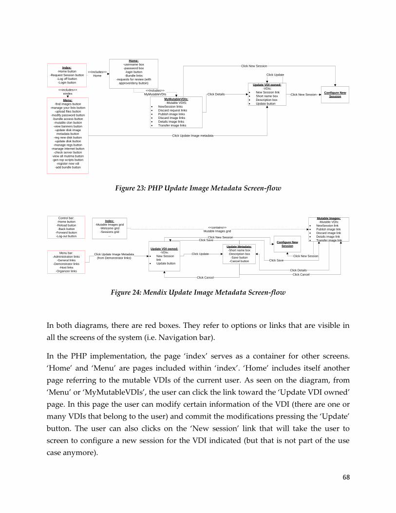
68
Home:
-username box
-password box
-login button
-Bundle links
-requests for review (with
approve/deny button)
Index:
-Home button
-Request Session button
-Log off button
-Login button
<<includes>>
Home
Menu:
-find images button
-manage your lists button
-upload files button
-modify password button
-bundle access button
-mutable clon button
-view banners button
-update disk image
metadata button
-reg new disk button
-update disk button
-manage regs button
-manage internet button
-check server button
-view all mutima button
-gen rep scripts button
-register new vdi
-add bundle button
<<includes>>
eindex Click Details
Click Update Image metadata
Update VDI owned:
-VDIs:
New Session link
Short name box
Description box
Update button
Click Update
Configure New
SessionClick New Session
MyMutableVDIs:
-Mutable VDIS:
NewSession links
Discard request links
Publish image links
Discard image links
Details image links
Transfer image links
<<includes>>
MyMutableVDIs
Click New Session
Figure 23: PHP Update Image Metadata Screen-flow
Menu bar:
-Administration links
-General links
-Demonstrator links
-Host links
-Organizer links
Control bar:
-Home button
-Reload button
-Back button
-Forward button
-Log-out button
Update VDI owned:
-VDIs:
New Session
link
Update button
Click Update Image Metadata
(from Demonstrator links)
Update Metadata:
-Short name box
-Description box
-Save button
-Cancel button
Click Update
Click Save
Click Cancel
Configure New
Session
Click New Session
Index:
-Mutable Images grid
-Welcome grid
-Sessions grid
...
Mutable Images:
-Mutable VDIs:
NewSession link
Publish image link
Discard image link
Details image link
Transfer image link
<<contains>>
Mutable Images grid
Click Details
Click Cancel
Click Save
Click New Session
Figure 24: Mendix Update Image Metadata Screen-flow
In both diagrams, there are red boxes. They refer to options or links that are visible in
all the screens of the system (i.e. Navigation bar).
In the PHP implementation, the page ‘index’ serves as a container for other screens.
‘Home’ and ‘Menu’ are pages included within ‘index’. ‘Home’ includes itself another
page referring to the mutable VDIs of the current user. As seen on the diagram, from
‘Menu’ or ‘MyMutableVDIs’, the user can click the link toward the ‘Update VDI owned’
page. In this page the user can modify certain information of the VDI (there are one or
many VDIs that belong to the user) and commit the modifications pressing the ‘Update’
button. The user can also clicks on the ‘New session’ link that will take the user to
screen to configure a new session for the VDI indicated (but that is not part of the use
case anymore).

69
For Mendix, the flow is similar: There are two bars that are visible all the time (‘Control’
and ‘Menu’). The ‘index’ screen is comparable to the ‘Home’ page in PHP. ‘Mutable
Images’ is a data grid that is contained within ‘index’. Similarly to the PHP
implementation, from the ‘Menu’ bar it is possible to access ‘Update VDI owned’. The
user can also access the screen ‘Update Metadata’ directly from the ‘Mutable Images’
(like ‘MyMutableVDIs’ of PHP). After the user accepts or cancel the edition of the
metadata, he will be redirected to the previous page (‘Update VDI owned’ or ‘Mutable
Images’).
The main difference between these two diagrams is that for Mendix, it is always
necessary to have an extra screen to alter information that can be accepted or canceled
afterwards. In the case of PHP, the data can be modified on the same screen on which it
is showed without need to have an extra screen. The links, buttons, boxes, etcetera;
remain the same in most cases. This occurs in the rest of the use cases and the system in
general.
In Table 14, the numbers concerned to the number of screens (nodes), the arcs, etc. are
displayed per use case. ‚Includes‛ and ‚contains‛ arcs are not taken into account
because such type of arcs does not indicate a user action or any kind of flow.
Number of
screens
Number of links Number of
different
screens
Number of
shared screens
Transfer
ownership
(PHP) 5
(Mendix) 6
(PHP) 4
(Mendix) 5
1 5
Take ownership
and make
mutable
(PHP) 4
(Mendix) 5
(PHP) 6
(Mendix) 6
1 4
Update Metadata
Image
(PHP) 6
(Mendix) 7
(PHP) 5
(Mendix) 9
1 6
Lists of Images (PHP) 8
(Mendix) 6
(PHP) 12
(Mendix) 11
2 6
Search Images (PHP) 8
(Mendix) 9
(PHP) 10
(Mendix) 8
1 8
Table 14: Quantitative comparison of Navigation and Presentation designs
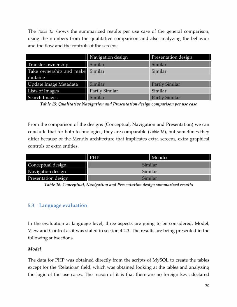
70
The Table 15 shows the summarized results per use case of the general comparison,
using the numbers from the qualitative comparison and also analyzing the behavior
and the flow and the controls of the screens:
Navigation design Presentation design
Transfer ownership Similar Similar
Take ownership and make
mutable
Similar Similar
Update Image Metadata Similar Partly Similar
Lists of Images Partly Similar Similar
Search Images Similar Partly Similar
Table 15: Qualitative Navigation and Presentation design comparison per use case
From the comparison of the designs (Conceptual, Navigation and Presentation) we can
conclude that for both technologies, they are comparable (Table 16), but sometimes they
differ because of the Mendix architecture that implicates extra screens, extra graphical
controls or extra entities.
PHP Mendix
Conceptual design Similar
Navigation design Similar
Presentation design Similar
Table 16: Conceptual, Navigation and Presentation design summarized results
5.3 Language evaluation
In the evaluation at language level, three aspects are going to be considered: Model,
View and Control as it was stated in section 4.2.3. The results are being presented in the
following subsections.
Model
The data for PHP was obtained directly from the scripts of MySQL to create the tables
except for the ‘Relations’ field, which was obtained looking at the tables and analyzing
the logic of the use cases. The reason of it is that there are no foreign keys declared

71
explicitly in the scripts but it is possible to identify the attributes that act as those by two
methods: looking at the comments of the scripts that sometimes indicate which
attributes are ‘foreign keys’ on that specific table. The other way is observing how the
data is modified within the PHP code and finding the links between the tables (part of
this was performed in the reengineering of the project).
In the Table 17, it can be observed that in the case of PHP, the number of tables (entities)
is almost always higher than the number of entities of Mendix. This is a bit
compensated with the number of attributes that are needed for the objects involved.
This number is a little bigger in Mendix because the number of entities involved (tables)
is lower resulting in fewer relations also. It is important just to remind that the lines of
code (LOC) do not apply in this study for Mendix but probably for further comparisons.
Use case PHP Mendix
Transfer
ownership
Entities 6 4
Attributes 50 48
Relations 9 6
LOC 72 -
Take ownership
and make
mutable
Entities 6 3
Attributes 42 36
Relations 8 2
LOC 69 -
Update Image
Metadata
Entities 3 3
Attributes 26 36
Relations 2 1
LOC 38 -
Lists of Images Entities 5 4
Attributes 32 38
Relations 5 4
LOC 52 -
Search Images Entities 4 3
Attributes 34 36
Relations 5 3
LOC 50 -
Table 17: Model comparison at Language level

72
View
On this aspect, the graphical controls were counted. For PHP were taken in account:
buttons, text fields, radio buttons, checkboxes, combo boxes, text areas, hyperlinks,
tables and image links. In the case of Mendix the controls were: combo boxes (includes
reference selector and reference set selector), buttons, hyperlinks, checkboxes, radio
buttons, text boxes, image links, rich text viewers and editors (equivalent to text areas),
data grids (tables). Certain controls were not taken into account in Mendix, such as
labels, HTML Snippets and static images, because those are controls just to show static
content that in PHP is just text within the code or with some HTML format. In the case
of images, if it doesn’t provide any functionality then they are not taken into account.
In the Table 18, it is possible to observe that Mendix uses slightly more graphical controls
than PHP. In part this is true because in PHP there is the possibility to reuse the same
controls for different data or the same screen to show and modify data. In Appendix I is
possible to observe the screens to modify the metadata of an image: in PHP it is just one
screen to display and edit the information while, on the other hand, Mendix needs two
screens for the same action.
Frequently, the controls that are going to appear depend on the validation of
parameters. Most of the times, this is not possible in Mendix; it just offers the chance to
show or not certain controls based on user roles or certain attributes of the entities but
the parameters passing is really limited. Instead, it provides the flexibility to add more
controls and forms easily than PHP without any line of code.
Use case PHP Mendix
Transfer
ownership
Tables 1 4
Data grids
Text fields 1 0
Radio buttons 0 0
Checkboxes 0 0
Text areas 0 0
Rich text viewers and
editors
Hyperlinks 2 (per image) 2(per image)
Image links 2 (per image) 2 (per image)
Buttons 1 1

73
Combo boxes 0 1
Reference selectors,
Reference set selectors
and Combo boxes
Take ownership
and make
mutable
Tables 1 (per image) 1
Data grids
Text fields 5 (per image) 5 (per image)
Radio buttons 0 4 (per image)
Checkboxes 1 (per image) 0
Text areas 1 (per image) 1 (per image)
Rich text viewers and
editors
Hyperlinks 2 (per image) plus 1
per each group
2(per image) plus 1
per each group
Image links 0 0
Buttons 1 (per image) 1 (per image)
Combo boxes 3 (per image) 2 (per image)
Reference selectors,
Reference set selectors
and Combo boxes
Update Image
Metadata
Tables 1 (per image) 1
Data grids
Text fields 1 (per image) 5 (per image)
Radio buttons 0 0
Checkboxes 0 0
Text areas 1 (per image) 2 (per image)
Rich text viewers and
editors
Hyperlinks 1 (per image) 1(per image)
Image links 0 0
Buttons 1 (per image) 3 (per image)
Combo boxes 0 0
Reference selectors,
Reference set selectors
and Combo boxes
Lists of Images
Tables 2 4
Data grids
Text fields 1 1

74
Radio buttons 0 0
Checkboxes 0 0
Text areas 1 per image 1 per image
Rich text viewers and
editors
Hyperlinks 3 plus 3 per list
plus 1 per image
1 plus 2 per list plus
1 per image
Image links 0 0
Buttons 1 (per image) 5 plus 1 (per image)
Combo boxes 0 0
Reference selectors,
Reference set selectors
and Combo boxes
Search Images Tables 1 5
Data grids
Text fields 4 4
Radio buttons 0 0
Checkboxes 1 0
Text areas 1 per image 1 per image
Rich text viewers and
editors
Hyperlinks 2 plus 1 per image
plus 1 per group
2 plus 1 per image
plus 1 per group
Image links 0 0
Buttons 1 3
Combo boxes 0 0
Reference selectors,
Reference set selectors
and Combo boxes
Table 18: View comparison at Language level
Control
Finally, for the control aspect the number of conditionals elements and HTTP requests
[86] related to the use cases were counted on PHP solution. Meanwhile, the number of
XOR splits, loops and number of activities within the microflows related to the use
cases were taken into account in the case of Mendix.
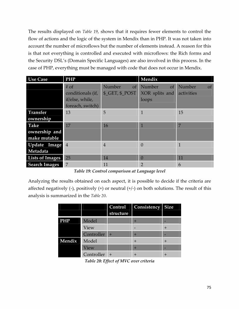
75
The results displayed on Table 19, shows that it requires fewer elements to control the
flow of actions and the logic of the system in Mendix than in PHP. It was not taken into
account the number of microflows but the number of elements instead. A reason for this
is that not everything is controlled and executed with microflows: the Rich forms and
the Security DSL’s (Domain Specific Languages) are also involved in this process. In the
case of PHP, everything must be managed with code that does not occur in Mendix.
Use Case PHP Mendix
# of
conditionals (if,
if/else, while,
foreach, switch)
Number of
$_GET, $_POST
Number of
XOR splits and
loops
Number of
activities
Transfer
ownership
13 5 1 15
Take
ownership and
make mutable
17 16 1 7
Update Image
Metadata
4 4 0 1
Lists of Images 25 14 0 11
Search Images 7 11 2 6
Table 19: Control comparison at Language level
Analyzing the results obtained on each aspect, it is possible to decide if the criteria are
affected negatively (-), positively (+) or neutral (+/-) on both solutions. The result of this
analysis is summarized in the Table 20.
Control
structure
Consistency Size
PHP Model + -
View - +
Controller + + -
Mendix Model + +
View + -
Controller + + +
Table 20: Effect of MVC over criteria

76
Using these results it is possible to conclude that the Understandability factor for PHP is
medium and for Mendix is high.
5.4 Tool evaluation
Using the matrix obtained in chapter 4, we are going to compare the characteristics
supported (marked with an ‘X’) or unsupported (without marking) by Mendix and PHP
IDEs in general. In the case of PHP, four tools were selected for the comparison because
of its popularity (Google page rank) and references in other comparisons [87] [88], due
to the fact that not specific tool was used for the development of the original SHARE
system.
PHP Mendix
PHPEclipse Komodo PhpED PHPEdit
Syntax
highlight
X X X X X
Syntax
checking
X X X X X
Debugging X X X X X
Navigation X X X X X
Versioning
system
X X X X
Multiple
language
support
X X X X X
Maturity
(High,
Medium,
Low)
High High Medium High Medium
Reusability X X X X X
Manual
coding
X X X X X
Model type
(UML,
DSL,
none none none none DSL

77
database,
none)
Model
transformat
ion and
refinement
support ?
Not apply Not apply Not apply Not apply No
Table 21: Tool matrix comparison for tools
As a result, Mendix holds the same features that most of PHP IDEs own. There are
certain characteristics that are not really evident in Mendix as they are in the IDEs for
PHP. An example could be debugging or manual coding because both are possible in
Mendix (set microflow debugging or java code) but they are not managed in deep as the
tools for PHP.
It would be interesting to measure the systems again but with the solution in PHP
developed with an IDE or being able to use other tool instead Mendix but that is part of
future work.
5.5 Summary
The comparison framework created in Chapter 4 was applied to evaluate both solutions
and technologies. Table 22 gives the results of the framework for PHP and Mendix.
Conceptual Completeness Correctness
Both Both
Design Conceptual Navigation Presentation
Similar Similar Similar
Language Understandability
(PHP)Medium
(Mendix)High
Tool Maturity Debugging Model Type …
(PHP) High
(Mendix) Medium
(PHP)
supported
(PHP) none
(Mendix) DSL
Etc.

78
(Mendix)
supported
Table 22: Comparison of both technologies
It was demonstrated that for both solutions the result of Conceptual and Design
classifications was similar (comparable) because the case study is the same and the
purpose was not to create something new, but to create what was already done on a
different platform. The requirements are the same and the intention was to provide the
same sense of feeling and using that user already has in the current implementation, in
terms of graphical interface and navigation.
It is not easy to compare both technologies in the Language design. The main reason is
because in Mendix there is no code at all (except for the XPath statements) and PHP is
purely based on it. The MVC architecture provided a method to compare both
technologies in three different aspects: Model, View and Controller.
Mendix has a DSL for each of the aspects of the MVC: Domain model, Rich forms and
Microflows. In the case of PHP, it just uses SQL for the Model and PHP with HTML
code for the other two aspects.
For understandability, Mendix is better than PHP because the model is easy to
understand with some introduction. The forms and the microflows are also easy to
understand. However, a drawback is that the notation used for associations in the meta-
model sometimes is difficult to fully understand [93]. The reason is that for many
developers it appears counterintuitive because they have been accustomed to UML
class diagrams. This becomes almost a burden as Mendix uses similar graphical
notation with different semantics. In the case of PHP, sometimes is really hard to
understand the code of the application because it is too much or because it is complex.
Additionally, without an E-R diagram, it takes time to understand the configuration of
the database.
Concerning about the tool, for Mendix there are not options like PHP has. The Mendix
tool consists in the business modeler, the model repository, the business server and the
rich client. For PHP there are many options: Komodo, PHPEclipse, PHPED, etc. In
general, both type of tools offer the same characteristics for their respective fields
(models vs code) but it is important to remark that the support and documentation for
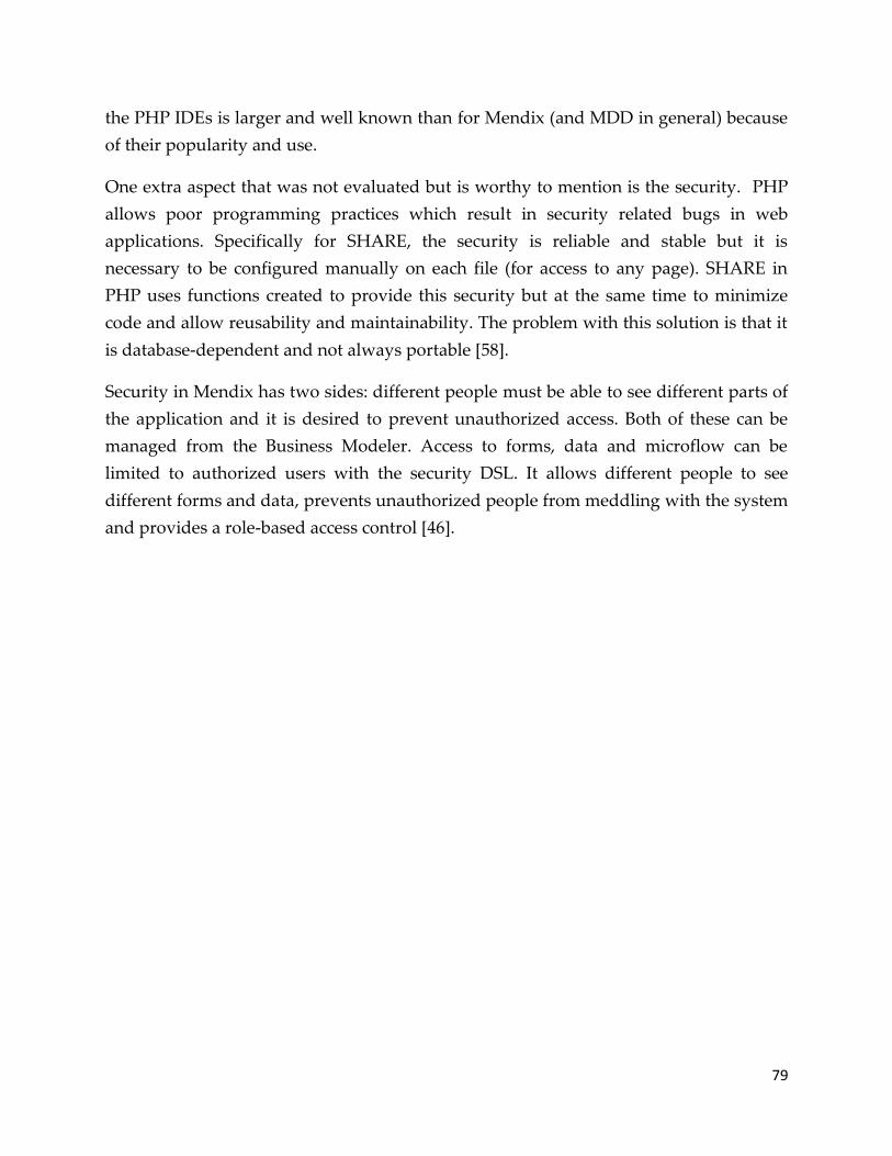
79
the PHP IDEs is larger and well known than for Mendix (and MDD in general) because
of their popularity and use.
One extra aspect that was not evaluated but is worthy to mention is the security. PHP
allows poor programming practices which result in security related bugs in web
applications. Specifically for SHARE, the security is reliable and stable but it is
necessary to be configured manually on each file (for access to any page). SHARE in
PHP uses functions created to provide this security but at the same time to minimize
code and allow reusability and maintainability. The problem with this solution is that it
is database-dependent and not always portable [58].
Security in Mendix has two sides: different people must be able to see different parts of
the application and it is desired to prevent unauthorized access. Both of these can be
managed from the Business Modeler. Access to forms, data and microflow can be
limited to authorized users with the security DSL. It allows different people to see
different forms and data, prevents unauthorized people from meddling with the system
and provides a role-based access control [46].
80
6 Conclusions
As a result of this study, it is possible not give an answer to the research question that
is:
Does the model-driven solution support the implementation of new features better
than the code-based solution?
It is hard to give an answer valid for all the cases. For this particular case, the model-
driven solution facilitates the implementation of new features but it is limited in the
functionality that it can provides due to the lack of experience in the technology and the
characteristics of the tool. As an example, it could be mentioned the difficult to
implement RSS in Mendix because it involves manually code in Java and some high
level of expertise with the tool. In the case of PHP, it already has libraries that facilitate
such implementation. On the other hand, with Mendix is easier to implement
functionality that implies search of information because the technology already
provides controls that facilitate this without any single line of code. To close this
question, in this case a model-driven solution allows or supports the implementation of
new features faster and easily but it does not imply that better. The expertise of the
developer really influences and also the maturity of the technology.
A generic MDE tool is suitable for the re-implementation of a code based prototype, at
least for web applications. But it is necessary to have gained knowledge about the tool
previously and take into account the maturity of the technology selected. One of the
challenges of realizing MDE is to unify the wealth of experience from work on code
generation, domain-specific languages, and other generative programming techniques
with the current momentum of the MDE initiative [15].
Issues and Benefits
From literature and after completing the new SHARE implementation, there have been
identified some benefits and issues about model driven development that apply not just
to this project but in general:
Model driven development introduces rigidity: The goal of MDD is to ‘program' on a
higher level of abstraction [94]. This means to specify less and generate more. However,
this also means that it is not possible to change every little detail that is wanted. It is, for

81
example, the case that generated graphical user interface are inflexible and they all look
like each other. In SHARE this is desirable, but it is not always the case. Additionally,
for Mendix the expertise about CSS is mandatory to modify the graphical interface.
Doing a project in a model-driven way with an inexperienced team can lead to at least
two problematic situations [94]. First, the solution will not be built on time and it will
not fulfill the customers' expectations due to the inexperience with the technology and
methodology approaches. Second, big chance the end product is not as easy to change
as it is expected from a solution built using a model-driven approach, due to misuse of
the tool, not knowing its limitations, or due to using immature tools.
Another issue is the insufficient support of tooling. Tooling is essential to maximize the
benefits of having models, and to minimize the effort required to maintain them [95].
Current programming languages (like PHP) are all supported by an integrated
development environment (IDE) making the writing and maintenance of code less
painful. An MDE methodology without supporting development tooling will not
deliver the benefits that are needed.
But also, MDD is faster to develop because the model of a software application is
specified on a higher abstraction level than traditional programming languages [96].
This model it is much smaller compared to the same model expressed in code so each
element in the model represents multiple lines of code.
Changing and maintaining applications build using an MDD approach is also more
cost-effective. It is easier to understand the behavior of an application by reading high-
level models. Additionally it is faster to add functionality or change existing
functionality using a high-level language [96].
MDD ensures that you can focus on testing the functionality of the application, i.e.
acceptance testing. Technical problems are covered by testing the MDD tool [96]. Even
the functionality itself is less-error prone when using an MDD approach, because
meaningful validations can be executed on the high-level models. When using
traditional programming languages we will have some syntax checking in the IDE and
maybe even some static code analyzers. However, due to the generality of the
programming language this does not really help to avoid functional errors. When using
an MDD approach domain-specific validations can be executed at design-time. The
resulting error message can be domain-specific too. In Mendix, the modeling
82
environment uses real-time consistency checking to ensure that the model is consistent
and can be executed by the runtime environment.
Last but not least, when using MDD it will not be incomplete or outdated
documentation, because the model is the documentation. When using the right
abstractions, the models are readable for domain experts and business owners [96].
Future Work
There is a lot of work on the area of model driven development. During this project,
there have been limitations and it has been possible to identify areas where future
studies could be applied.
Including the cloud computing aspect in the re-implementation of SHARE is an
interesting task for next studies. Mendix provides this service to its clients but it would
be valuable to check if it is possible the use of virtual machines in their cloud and how
this affects the re-implementation of SHARE with Mendix.
It is also a task for the future to execute this study on a more widely known and probed
application like the Java Pet Store. It would serve to verify the advantages that Mendix
aims to provide, comparing such implementation with others code approaches (Java,
.NET) [39] or even model driven approaches but in terms of maintainability and not just
productivity [97] [98].
Mendix does not perform model refinement or model transformation. A comparison of
this same case study but using other MDD tools that support such kind of functions
would help to compare if that kind of tools is better or not than Mendix in terms of
maintainability even if it implies more time or knowledge about model driven
development.
Finally, the inclusion of more criteria for the maintainability at language level –referring
to modifiability, portability and testability- would aggregate value to the study and
perhaps, it could generate different conclusions about the maintainability of model
driven applications.

83
7 Bibliography
[1] D. D'Souza. (2001) Model Driven Architecture - A Technical Perspective.
[2] P. Mohagheghi and V. Dehlen, "Where is the proof?-a review of experiences from
applying mde in industry," in , 2008, pp. 432--443.
[3] D. C. Schmidt, "Guest editors introduction: Model-driven engineering," Computer,
vol. 39, pp. 25--31, 2006.
[4] J. Hutchinson, J. Whittle, M. Rouncefield, and S. Kristoffersen, "Empirical
assessment of MDE in industry," in , 2011, pp. 471--480.
[5] I. Schieferdecker and A. Hartman, Model driven architecture: foundations and
applications: 4th European conference, ECMDA-FA 2008, Berlin, Germany, June 9-13,
2008; proceedings. Springer-Verlag New York Inc, 2008, vol. 5095.
[6] D. A. a. F. M. a. S. J. E. a. G. J. D. Ghazaleh, "Method and apparatus for
documenting and describing object oriented programming logic," U.S. Patent
UNKNOWN, Sep. 2003.
[7] R. F. Clippinger, "A Logical Coding System Applied to the ENIAC," 1948.
[8] J. E. Sammet and D. Hemmendinger, Programming languages. John Wiley and Sons
Ltd., 2003.
[9] D. Sureau. (2011, May) History of Programming Languages and their Evolution.
[Online]. http://www.scriptol.com/programming/history.php
[10] P. P. Chen, "The entity-relationship model---toward a unified view of data," ACM
Transactions on database systems, vol. 1, pp. 9--36, 1976.
[11] P. Grogono. (2002) Course Notes for COMP 348 and COMP 6411.
[12] P. S. a. S. S. Rene Heinzl, "Modern Concepts for High-Perfomance Scientific
Computing - Library Centric Application Design," in Proceedings of the 2nd ICSOFT

84
2007, Barcelona, 2007, pp. 100-107.
[13] R. Johnson, "J2EE development frameworks," Computer, vol. 38, pp. 107--110, 2005.
[14] J. B. Warmer and A. G. Kleppe, "The Object Constraint Language: Precise
Modeling With Uml (Addison-Wesley Object Technology Series)," 1998.
[15] A. Van Deursen, E. Visser, and J. Warmer, "Model-driven software evolution: A
research agenda," MoDSE, vol. 7, pp. 41--49, 2007.
[16] D. Ameller, "Considering Non-Functional Requirements in Model-Driven
Engineering," Master Thesis, Barcelona, 2009.
[17] T. Goldschmidt and J. Klübler, "Towards Evaluating Maintainability Within
Model-Driven Environments," Software Engineering, 2008.
[18] A. Rutle, U. Wolter, and Y. Lamo, "A formal approach to modeling and model
transformations in software engineering," 2008.
[19] R. D. Banker, S. M. Datar, C. F. Kemerer, and D. Zweig, "Software complexity and
maintenance costs," Communications of the ACM, vol. 36, pp. 81--94, 1993.
[20] J. L. Wynekoop and N. L. Russo, "Studying system development methodologies:
an examination of research methods," Information Systems Journal, vol. 7, pp. 47--
65, 1997.
[21] J. Rowley, "Using case studies in research," Management Research News, vol. 25, pp.
16--27, 2002.
[22] K. M. Eisenhardt, "Building theories from case study research," Academy of
management review, pp. 532--550, 1989.
[23] P. Van Gorp and P. Grefen, "Supporting the internet-based evaluation of research
software with cloud infrastructure," Software and Systems Modeling, pp. 1--18, 2010.
[24] G. Kappel, B. Pröll, S. Reich, and W. Retschitzegger, Web engineering. John Wiley &
Sons, 2006.
85
[25] S. Murugesan, Y. Deshpande, S. Hansen, and A. Ginige, "Web engineering: A new
discipline for development of web-based systems," Web Engineering, pp. 3--13,
2001.
[26] T. Isakowitz, M. Bieber, and F. Vitali, "Web information systems," Communications
of the ACM, vol. 41, pp. 78--80, 1998.
[27] B. W. Boehm, J. R. Brown, and M. Lipow, "Quantitative evaluation of software
quality," in , 1976, pp. 592--605.
[28] M. Frappier, S. Matwin, and A. Mili, "Maintainability: Factors and Criteria," vol. 1,
1994.
[29] L. F. Stella, S. Jarzabek, and B. Wadhwa, "A comparative study of maintainability
of web applications on J2EE,. NET and Ruby on Rails," in , pp. 93--99.
[30] "IEEE Standard Glossary of Software Engineering Terminology," 1990.
[31] H. Ma, W. Shao, L. Zhang, Z. Ma, and Y. Jiang, "Applying OO Metrics to Assess
UML Meta-models," in The Unified Modeling Language. Modelling Languages and
Applications. Springer, 2004.
[32] J. McQuillan and J. Power, "On the Application of Software Metrics to UML
Models," in Models in Software Engineering. Springer, 2007.
[33] S. Spaccapietra, S. T. March, and Y. Kambayashi, Conceptual Modeling-ER 2002:
21st International Conference on Conceptual Modeling, Tampere, Finland, October 7-11,
2002: Proceedings. Springer Verlag, 2002.
[34] M. Gally, "What is MDD/MDA and where will it lead the software development in
the future?".
[35] B. Anda and K. Hansen, "A case study on the application of UML in legacy
development," in , 2006, pp. 124--133.
[36] P. Baker, S. Loh, and F. Weil, "Model-driven engineering in a large industrial
contextâ€‛Motorola case study," Model Driven Engineering Languages and Systems,

86
pp. 476--491, 2005.
[37] I. Rychkova, G. Regev, L. S. Le, and A. Wegmann, "From Business To IT with
SEAM: the J2EE Pet Store Example," in , 2007, pp. 495--495.
[38] J. Shirazi, Java performance tuning. OReilly Media, 2003.
[39] T. M. Company. (2004) The Middleware Company. [Online].
http://people.cis.ksu.edu/~hankley/d764/PetStoreComparison.html
[40] Sygel. Sygel, the future is out there.
[41] J. Bezivin, "On the unification power of models," Software and Systems Modeling,
vol. 4, pp. 171--188, 2005.
[42] OMG. (2002, Aug.) Object and Reference Model AB Subcomittee. [Online].
http://ormsc.omg.org/mda_guide_working_page.htm
[43] S. J. Mellor, T. Clark, and T. Futagami, "Model-driven development: guest editors
introduction.," IEEE software, vol. 20, pp. 14--18, 2003.
[44] F. P. Brooks, "No silver bullet: Essence and accidents of software engineering,"
IEEE computer, vol. 20, pp. 10--19, 1987.
[45] N. Moreno, J. R. Romero, and A. Vallecillo, "An overview of model-driven web
engineering and the mda," Web Engineering: Modelling and Implementing Web
Applications, pp. 353--382, 2008.
[46] Mendix. (2011) Mendix. [Online]. www.mendix.com/product
[47] Object Management Group - UML. [Online]. www.uml.org
[48] I. T. Chapter, "What Is UML?".
[49] UML Diagrams. [Online]. http://www.uml-diagrams.org/uml-24-diagrams.html
[50] Business Process Management Initiative. [Online].
http://www.bpmn.org/Documents/FAQ.htm

87
[51] R. Simpson, "An XML Representation for Crew Procedures," 2005.
[52] S. A. White, "Process modeling notations and workflow patterns," Workflow
Handbook, pp. 265--294, 2004.
[53] S. A. White, "Introduction to BPMN," IBM Cooperation, pp. 2008--029, 2004.
[54] A. N. Langville and C. D. Meyer, Google page rank and beyond. Princeton Univ Pr,
2006.
[55] Skelta Invensys. (2009, Mar.) Skelta Software. [Online].
http://www.skelta.com/company/2009/Skelta-named-Gartner-Cool-Vendor.aspx
[56] Bizagi. (2010, Apr.) Bizagi BPMS. [Online].
http://www.bizagi.com/index.php?option=com_content&view=article&id=204cati
d=10&Itemid=95
[57] OutSystems. (2008, Apr.) Outsystems. [Online].
http://www.outsystems.com/company/news/200X/cool-vendor/
[58] K. Purer, "PHP vs. Python vs. Ruby--The web scripting language shootout," 2009.
[59] S. Artzi, et al., "Finding bugs in dynamic web applications," in , 2008, pp. 261--272.
[60] D. Marshall. (2004) PHP Handout.
[61] G. van Emde Boas, "Generative and Model-Driven Approaches for PHP".
[62] GBDirect. GBdirect E-Commerce Consultancy Training and Software
Development. [Online].
http://training.gbdirect.co.uk/courses/php/comparison_php_versus_perl_vs_asp_j
sp_vs_vbscript_web_scripting.html
[63] L. Wall, The Perl programming language. Prentice Hall Software Series, 1994.
[64] J. C. Sandvig, "Active Server Pages," The Internet Encyclopedia, 2004.
[65] A. Server, "Java Server Pages," Notes, vol. 27, pp. 1--129, 2002.

88
[66] TIOBE Software. TIOBE programming community index. [Online].
http://www.tiobe.com/index.php/content/paperinfo/tpci/index.html
[67] D. Chuang, "PHP in a Dynamic Web Site Development Advantages".
[68] S. Demeyer, S. Ducasse, and O. M. Nierstrasz, Object-oriented reengineering patterns.
Morgan Kaufmann, 2003.
[69] S. W. Ambler. (2009) Agile Modeling. [Online].
http://www.agilemodeling.com/essays/amdd.htm
[70] E. J. Chikofsky and J. H. Cross, "Reverse engineering and design recovery: A
taxonomy," Software, IEEE, vol. 7, pp. 13--17, 1990.
[71] M. Fowler, UML distilled: a brief guide to the standard object modeling language.
Addison-Wesley Professional, 2004.
[72] N. Grozev, "A comparison of component-based software engineering and model-
driven development from the ProCom perspective," 2011.
[73] T. Özgür, "Comparison of Microsoft DSL tools and eclipse modeling frameworks
for domain-specific modeling in the context of the model driven development,"
School of Engineering. Ronneby, Sweden, Blekinge Institute of Technology, p. 56, 2007.
[74] K. Krogmann and S. Becker, "A Case Study on Model-Driven and Conventional
Software Development: The Palladio Editor," in , vol. 106, 2007, pp. 169--176.
[75] P. Van Gorp and R. Eshuis, "Transforming process models: executable rewrite
rules versus a formalized java program," Model Driven Engineering Languages and
Systems, pp. 258--272, 2010.
[76] K. Bittner and I. Spence, Use case modeling. Addison-Wesley Professional, 2003.
[77] P. Barna, F. Frasincar, G. J. Houben, and R. Vdovjak, "Methodologies for web
information system design," in , 2003, pp. 420--424.
[78] A. Gemino and Y. Wand, "A framework for empirical evaluation of conceptual
89
modeling techniques," Requirements Engineering, vol. 9, pp. 248--260, 2004.
[79] I. Davies, P. Green, M. Rosemann, M. Indulska, and S. Gallo, "How do
practitioners use conceptual modeling in practice?," Data & Knowledge Engineering,
vol. 58, pp. 358--380, 2006.
[80] C. S. Ramos, K. M. Oliveira, and N. Anquetil, "Legacy software evaluation model
for outsourced maintainer," in , pp. 48--57.
[81] B. W. Boehm and T. Systems, "Characteristics of software quality," 1978.
[82] M. Frappier, S. Matwin, and A. Mili, "Maintainability: Factors and Criteria,"
Software Metrics Study, Tech. Memo, vol. 1.
[83] H. D. Rombach and B. T. Ulery, "Improving software maintenance through
measurement," Proceedings of the IEEE, vol. 77, pp. 581--595, 1989.
[84] N. E. Fenton and S. L. Pfleeger, "Software metrics: a rigorous and practical
approach," Methods, vol. 5, p. 26, 2009.
[85] S. Burbeck, Applications Programming in Smalltalk-80: How to Use Model-View-
Controller (MVC). Softsmarts, Inc., 1987.
[86] J. E. Sweat, PHP] Architects Guide to PHP Design Patterns. php/architect
NanoBooks, 2005.
[87] J. Herrington. (2006, Oct.) IBM DeveloperWorks. [Online].
http://www.ibm.com/developerworks/library/os-php-ide/
[88] M. A. (2009, Feb.) Smashing Coding. [Online].
http://coding.smashingmagazine.com/2009/02/11/the-big-php-ides-test-why-use-
oneand-which-to-choose/
[89] T. Kapteijns, S. Jansen, S. Brinkkemper, H. Houët, and R. Barendse, "A
Comparative Case Study of Model Driven Development vs Traditional
Development: The Tortoise or the Hare," From code centric to model centric software
engineering: Practices, Implications and ROI, p. 22, 2004.

90
[90] A. Leue. (2011, Jun.) The Model Driven Software Network. [Online].
http://www.modeldrivensoftware.net/forum/topics/how-to-compare-model-
driven?xg_source=activity
[91] L. Von Ahn, M. Blum, N. Hopper, and J. Langford, "CAPTCHA: Using hard AI
problems for security," Advances in Cryptology—EUROCRYPT 2003, pp. 646--646,
2003.
[92] Miscellaneous: TO DO.
[93] M. Henkel and J. Stirna, "Pondering on the key functionality of model driven
development tools: The case of mendix," Perspectives in Business Informatics
Research, pp. 146--160, 2010.
[94] J. den Haan. (2009, Jun.) 8 reasons why Model-Driven Development is dangerous.
[Online]. http://www.theenterprisearchitect.eu/archive/2009/06/25/8-reasons-why-
model-driven-development-is-dangerous
[95] J. den Han. (2008, Jul.) 8 Reasons Why Model-Driven Approaches (will) Fail.
[Online]. http://www.infoq.com/articles/8-reasons-why-MDE-fails#Sol06
[96] J. den Haan. (2009, Nov.) 15 reasons why you should start using Model Driven
Development. [Online].
http://www.theenterprisearchitect.eu/archive/2009/11/25/15-reasons-why-you-
should-start-using-model-driven-development
[97] S. Witkop, "Driving business agility with Model Driven Architecture," Electronic
Data Systems Corporation, Texas, 2003.
[98] D. Herst and E. Roman, "Model Driven Development for J2EE Utilizing a Model
Driven Architecture (MDA)-Approach: A Productivity Analysis," TMC Research
Report, 2003.
[99] Systems, Invensys. (2011) Skelta Software, A BPM Software Company. [Online].
http://www.skelta.com/company/about-skelta.aspx
[100] OutSystems. Agile Development for Enterprise Web Applications - OutSystems.

91
[Online]. http://www.outsystems.com/agile-platform/
[101] Mendix. (2008, Apr.) The Business Agility Blog. [Online].
http://www.mendix.com/tag/gartner/
[102] Changing Minds. Changing Minds. [Online].
http://changingminds.org/explanations/research/sampling/choosing_sampling.ht
m

92
Appendix A
Use Case ID
A unique ID to use as a reference for this Use Case.
Title
A representative title for the Use Case
Version
A versioning system is useful to track and manage this and the
version identifier should be included here. For the purposes of this study, the version for all cases will be the 1.0
Goal
The goal is a brief description of the intent of the Use Case from a user’s perspective.
Summary
This section should provide a quick overview of the use case as it currently stands, reflecting the full description of the Use Case as
authored by development colleagues.
Actors
An actor is either a human or non-human entity that either acts on the system (a primary actor) or is acted on by the system (a
secondary actor). An actor could be a human, a mechatronic device or another software system or sub-system.
Preconditions
The preconditions are a set of actions or events that must happen in order to reach a state on which the case may occur. As an example,
consider an automated teller machine (ATM). A set of preconditions for a Use Case could be:
Card reader and pin-pad are enabled Connection between ATM and host is established
Card-holder possess a valid card ATM displaying “Welcome” screen

93
Basic course of events
This section describes the natural flow of events in the Use Case in its basic, idealised state. Taking the ATM example from above, we
could have: ATM displays the “Welcome” screen
Card-holder enters a valid card ATM prompts card-holder to enter PIN
Card-holder enters valid PIN ATM authenticates card-holder credentials
ATM displays “Menu” screen
Alternative paths
This is where negative flows can be anticipated and negative tests identified. However, it can also be considered as extending the basic
course of events to include alternative (and valid) paths through the system.
Alternative paths make use of the numbering of the basic course of events to show at which point they differ from the basic scenario,
and, if appropriate, where they rejoin. The intention is to avoid repeating information unnecessarily.
Post-conditions
The post-conditions are the state the system is left in as a result of
running through the basic course of events or through one of the alternative paths. These may form the pre-conditions for other Use
Cases and you may wish to make reference to them is appropriate.
Taking the ATM example again, post-conditions could be:
All devices have correctly reported status “Menu” screen is displayed
Card is held within card-reader Timeout period has started
Screen cast
A link to the screencast of the use case is on this section. The screencast will serve as a test case indicating the basic flow and sometimes, some alternative flows of the Use Case.

94
Appendix B
Use Case ID
TO01
Title
Transfer Ownership
Version
1.0
Goal
Transfer the ownership of a Mutable Virtual Disk Image to another user that
belongs to the same bundle
Summary
The Owner of the Mutable Virtual Disk Image indicates that he wants to
transfer certain MVDI, clicking on the respective link in the main page. The
system shows a screen where the e-mail of the target user is introduced or
selected and the system indicates if the transfer was successful or not. In
addition, an email is sent to the organizer of the bundle, the owner of the
MVDI and the target user informing them about the transaction.
Actors
Image Owner
Preconditions
The user must be registered in the system
The user must have at least one mutable image that is not in any of the
following states: ‚pending‛, ‚active‛ or ‚stop requested‛ and which
period of usability is still active
Basic course of events
1. The system displays the mutable VDI’s that haven’t been published or
discarded yet that belongs to the Image Owner (current user)
2. The user clicks on the hyperlink to transfer the VDI

95
3. The system asks to the user to type the e-mail of the target user
4. The user types or selects the e-mail and press the button
5. The system shows a message indicating the success of the transaction
6. An email is sent to the corresponding users: Organizer, Image Owner
and Target user
Alternative paths
4.1 The system shows that the VDI doesn’t exist
4.2 The system shows that the target user doesn’t belong to the bundle of the
VDI.
4.3 The system throws an exception and it is indicated that an e-mail (user)
has to be selected.
Post-conditions
The Home page is displayed
The VDI doesn’t appear anymore to the user as part of its mutable
images
The mutable VDI now belongs to the target user that becomes in a
Demonstrator also.
Screen cast
http://screenr.com/F20s
Use case for transfer ownership
Use Case ID
TOM01
Title
Take ownership and make mutable
Version
1.0
Goal

96
Take the owner of the VDI and make it mutable at the same time.
Summary
An organizer selects a bundle and if he is the organizer of it, all the images of
that group are display along with certain data. The user clicks on a hyperlink
that is displayed as ‚take ownership and make mutable‛ in order to execute
such actions over the VDI. After this, the organizer will have private mutable
access to the VDI and the ownership of it.
Actors
Organizer
Preconditions
The user must be an organizer of one bundle (at least)
The group must contain at least one image
The user must select a bundle before
Basic course of events
1. The user selects the option ‚Update Disk‛
2. The user selects a single group or all the groups on which he is the
Organizer at once.
3. The system displays the VID’s that belong to the bundle selected
4. The user clicks on the hyperlink to take the ownership and make the
VDI mutable
5. The system shows a message to the user to indicate that he has a
private access to the image.
Alternative paths
3.1 The system shows that the user is not the Organizer of the bundle, or the
image is offline, or it is already mutable
3.2 The system shows that the image is deployed across multiple servers so
then, it cannot be mutable
Post-conditions
The Home page is displayed
The user is the only one that can request a session when the VDI has
been assigned to the organizer (this occurs via cron jobs that update the
data)

97
Screen cast
http://screenr.com/UU0s
Use case for take ownership and make image mutable
Use Case ID
MD01
Title
Update Image Metadata
Version
1.0
Goal
Update certain data (short name and description) of the VDI
Summary
The system retrieves all the images that belong to the demonstrator. The
demonstrator can edit the description and the short name of these images but
individually. There is a button per image that commits these changes.
Actors
Demonstrator
Preconditions
The user must be a demonstrator of one image (at least)
Basic course of events
1. The system displays the VDI’s that has de demonstrator and their
details.
2. The demonstrator clicks on the button to update the information
3. The demonstrator edit the information of the VDI
4. The details of the VDI are updated
Alternative paths
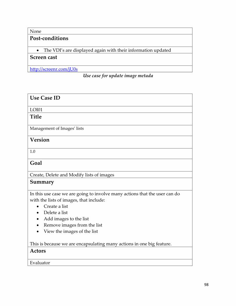
98
None
Post-conditions
The VDI’s are displayed again with their information updated
Screen cast
http://screenr.com/jU0s
Use case for update image metada
Use Case ID
LOI01
Title
Management of Images’ lists
Version
1.0
Goal
Create, Delete and Modify lists of images
Summary
In this use case we are going to involve many actions that the user can do
with the lists of images, that include:
Create a list
Delete a list
Add images to the list
Remove images from the list
View the images of the list
This is because we are encapsulating many actions in one big feature.
Actors
Evaluator
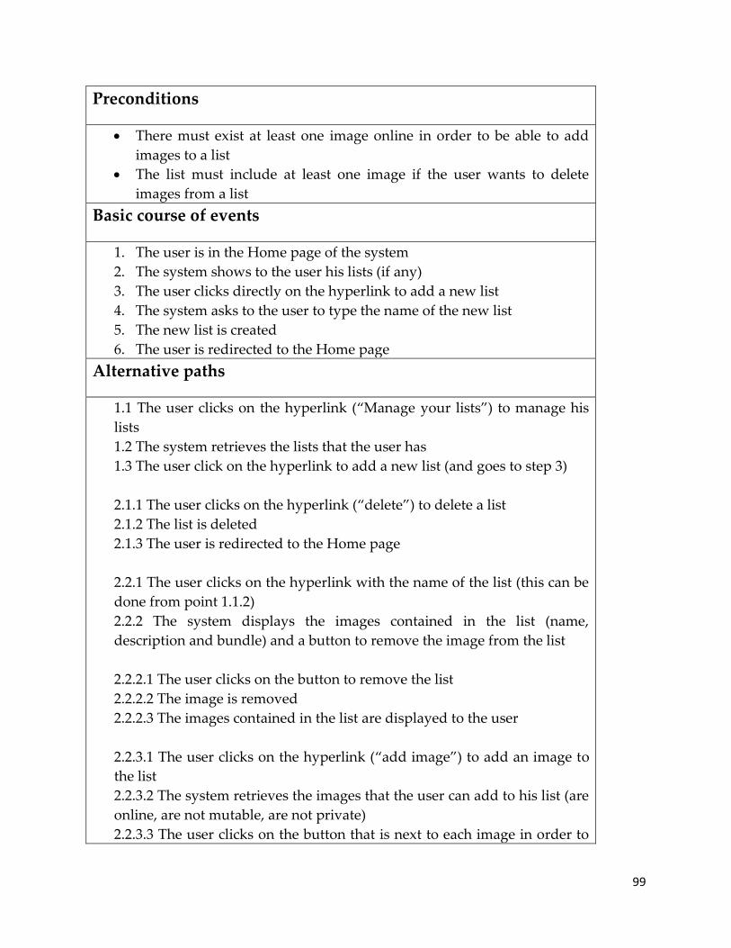
99
Preconditions
There must exist at least one image online in order to be able to add
images to a list
The list must include at least one image if the user wants to delete
images from a list
Basic course of events
1. The user is in the Home page of the system
2. The system shows to the user his lists (if any)
3. The user clicks directly on the hyperlink to add a new list
4. The system asks to the user to type the name of the new list
5. The new list is created
6. The user is redirected to the Home page
Alternative paths
1.1 The user clicks on the hyperlink (‚Manage your lists‛) to manage his
lists
1.2 The system retrieves the lists that the user has
1.3 The user click on the hyperlink to add a new list (and goes to step 3)
2.1.1 The user clicks on the hyperlink (‚delete‛) to delete a list
2.1.2 The list is deleted
2.1.3 The user is redirected to the Home page
2.2.1 The user clicks on the hyperlink with the name of the list (this can be
done from point 1.1.2)
2.2.2 The system displays the images contained in the list (name,
description and bundle) and a button to remove the image from the list
2.2.2.1 The user clicks on the button to remove the list
2.2.2.2 The image is removed
2.2.2.3 The images contained in the list are displayed to the user
2.2.3.1 The user clicks on the hyperlink (‚add image‛) to add an image to
the list
2.2.3.2 The system retrieves the images that the user can add to his list (are
online, are not mutable, are not private)
2.2.3.3 The user clicks on the button that is next to each image in order to

100
add it to his list
2.2.3.4 The image is added to the list
2.2.3.5 The images contained in the list are displayed to the user
4.1 The name of the list already exists
4.2 The system displays an alert to the user indicating that the list couldn’t
be created and that he has to choose a different name
Post-conditions
The lists are created, deleted or updated (during the alternative paths
the post conditions were also indicated)
Screen cast
http://screenr.com/AS0s
Use case for management of images’ lists
Use Case ID
SI01
Title
Search Image
Version
1.0
Goal
Find images introducing certain criteria
Summary
The system retrieves all the images that follow certain criteria introduced by
the user. The user can be registered in the system or not, but the results are
going to be the same; excepting that if the user is authenticated, the results
also will show which images belong to the user (if any).
Actors
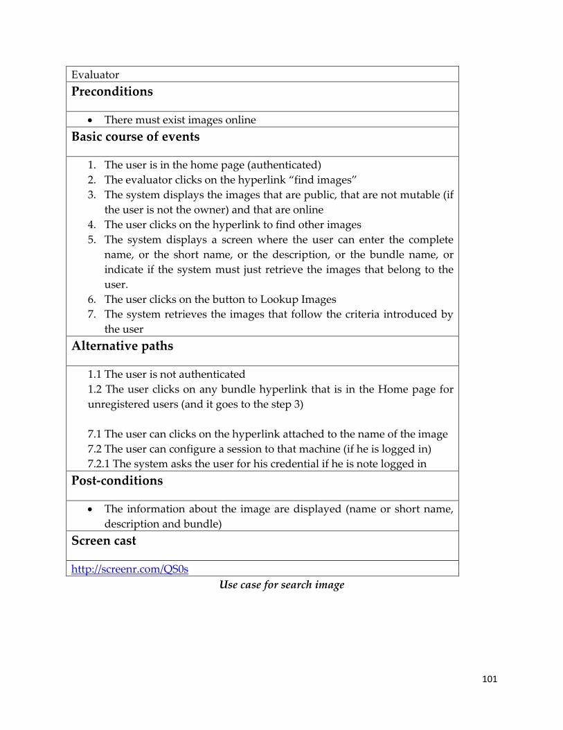
101
Evaluator
Preconditions
There must exist images online
Basic course of events
1. The user is in the home page (authenticated)
2. The evaluator clicks on the hyperlink ‚find images‛
3. The system displays the images that are public, that are not mutable (if
the user is not the owner) and that are online
4. The user clicks on the hyperlink to find other images
5. The system displays a screen where the user can enter the complete
name, or the short name, or the description, or the bundle name, or
indicate if the system must just retrieve the images that belong to the
user.
6. The user clicks on the button to Lookup Images
7. The system retrieves the images that follow the criteria introduced by
the user
Alternative paths
1.1 The user is not authenticated
1.2 The user clicks on any bundle hyperlink that is in the Home page for
unregistered users (and it goes to the step 3)
7.1 The user can clicks on the hyperlink attached to the name of the image
7.2 The user can configure a session to that machine (if he is logged in)
7.2.1 The system asks the user for his credential if he is note logged in
Post-conditions
The information about the image are displayed (name or short name,
description and bundle)
Screen cast
http://screenr.com/QS0s
Use case for search image
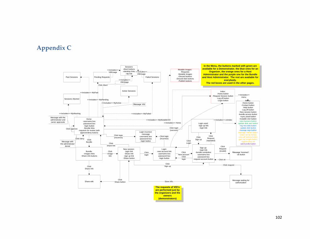
102
Appendix C
Home:
-username box
-password box
-login button
-Bundle links
-requests for review (with
approve/deny button)
Bundle:
-images links
-Share info buttons
Click
Bundle
Share wiki
Click
Share info
New session:
-login link
-Share link
-sign up link
-Share button
Click
Image
link
Click
Share link
Login:
-new account link
-username box
-password box
-login button
Click
login
Sign up:
-login link
-bundle combobox
-username box
-password box
-request account button
Click
New account
Click
Sign up
Click
Share button
Message ‘incorrect’:
-ok button
Click
Request
(invalid)
Click ok
Login used:
-sign up link
-login link
Click
Request
(repeated)
Click
Sign up
Message waiting for
authorization
Click request
Store info
Click login
(incorrect)
Click login
(incorrect)
Click
Login
Login incorrect
-message
-username box
-password box
-login button
<<includes>> MyAborting
Sessions Aborted
Past Sessions Pending Requests
<<includes>> MyPast
<<includes>> MyPending
<<includes>> MyFailed
<<includes>> MyActive
<<includes>> MyMutableVDI
Active Sessions
Failed Sessions
Mutable Images:
-Requests
-Mutable Images
-Discard buttons
-Discard disk buttons
-Publish buttons
Click
login
Index:
-Home button
-Request Session button
-Log off button
-Login button
Click login
(success)
<<includes>> Home
Menu:
-Home button
-Contact button
-Help button
-Log off button
-New session button
-bundle access button
-rsync pswd button
-mutable clon button
-view banners button
-update disk own button
-reg new disk button
-update disk button
-manage regs button
-manage internet button
-check server button
-view all mutima button
-gen rep scripts button
-register new vdi
-add bundle button
<<includes>> enindex
<<includes>>
menu
In the Menu, the buttons marked with green are
available for a Demonstrator, the blue ones for an
Organizer, the orange ones for a Host
Administrator and the purple one for the Bundle
and Host Administrator. The rest are available for
everybody.
The red boxes are used in the other pages.
Sessions
-Abort buttons
-rdesktop links
-rdp link<<includes>>
VMUsage
<<includes>>
VMUsage
<<includes>>
VMUsage
Click Abort
Click approve
Click deny
Message with
the administrator
denial
Message with the
administrator and
owner approvals
The requests of VDI’s
are performed just by
the organizers and the
owners
(demonstrators)
Message ‘info’

103
Screen flow of the base system (Part A: Index Page)
Index:
-Home button
-Request Session button
-Log off button
-Login button
Click
Home
IS groupClick
contact
Share wikiClick
Help
Logoff:
-message
Click
Log off
Destroy
Session
View Banners:
-banners
-banners links
-new session links
-facebook links
-facebook profile
links
-digo links
-digo bookmarks
-bibtex links
-new session
boxes
-facebook boxes
-digo boxes
-bibtex boxes
Click
View banners
Click
Banner link
website(new
window)
Click
link
Digo document
(new window)
Click digo
link
Bibtex website
(new window)
Click bibtex
link
New session:
-vm combo box
-date box
-hour box
-minute box
-duration box
-request button
Handle New
Session
Click request
(succed)
Click request
(failed)
Rsync password:
-hide/show pswd
link
-new password
box
-submit button
-command upload
-mounting info
Click
Rsync pswd
Click
Submit
Bundle access:
-registered
bundles
-pending requests
-bundles
combobox
-request button
Click
Bundle access
Click
request
Message
‘info’
Mutable clone:
-disk image
combobox
-mnemonic box
-durationbox
-request button
Click mutable clon
Click
request
Message
‘info’
Message ‘reason:
-Share button<<includes>> enindex
Menu:
-bundle access button
-rsync pswd button
-mutable clon button
-view banners button
-update disk own button
-reg new disk button-
update disk button
-manage regs button
-manage internet button
-check server button
-view all mutima button
-gen rep scripts button
-register new vdi
-add bundle button
Click request
(failed)
Screen flow of the base system (Part B: Menu Page 1)
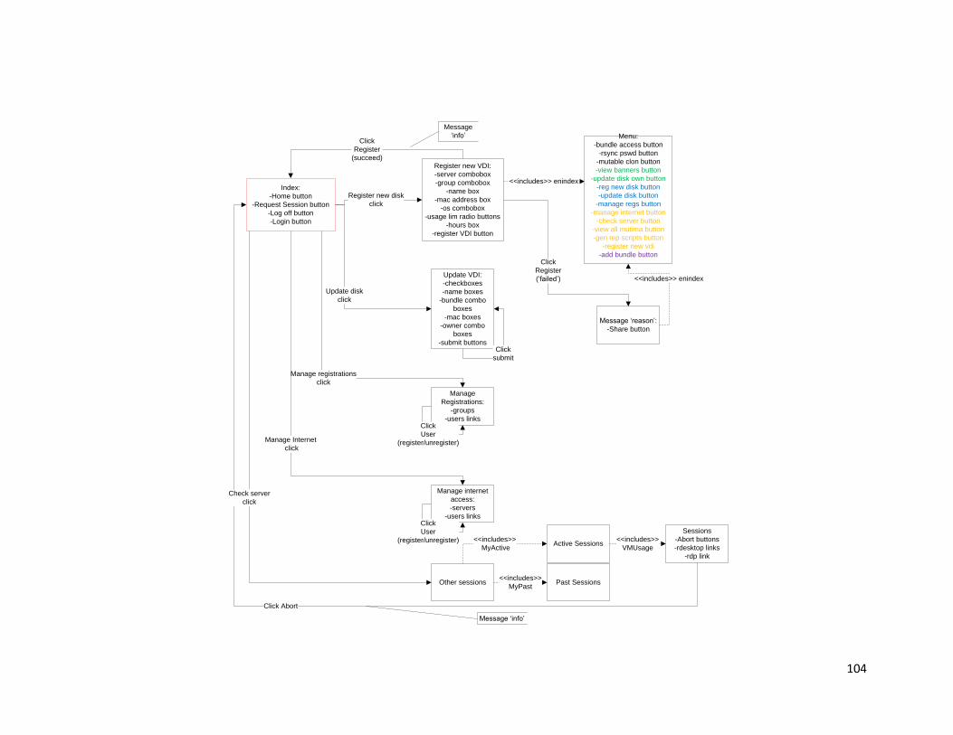
104
Index:
-Home button
-Request Session button
-Log off button
-Login button
Register new VDI:
-server combobox
-group combobox
-name box
-mac address box
-os combobox
-usage lim radio buttons
-hours box
-register VDI button
Register new disk
click
Click
Register
(succeed)
Message
‘info’
<<includes>> enindex
Menu:
-bundle access button
-rsync pswd button
-mutable clon button
-view banners button
-update disk own button
-reg new disk button
-update disk button
-manage regs button
-manage internet button
-check server button
-view all mutima button
-gen rep scripts button
-register new vdi
-add bundle button
Update VDI:
-checkboxes
-name boxes
-bundle combo
boxes
-mac boxes
-owner combo
boxes
-submit buttons
Update disk
click
Message ‘reason’:
-Share button
Click
Register
(‘failed’) <<includes>> enindex
Click
submit
Manage
Registrations:
-groups
-users links
Manage registrations
click
Click
User
(register/unregister)
Manage internet
access:
-servers
-users linksClick
User
(register/unregister)
Manage Internet
click
Other sessions
<<includes>>
MyActiveActive Sessions
Sessions
-Abort buttons
-rdesktop links
-rdp link
<<includes>>
VMUsage
Click Abort
Message ‘info’
Check server
click
Past Sessions<<includes>>
MyPast

105
Screen flow of the base system (Part B: Menu Page 2)
Index:
-Home button
-Request Session button
-Log off button
-Login button
Virtual machines on
host:
- not yet deployed links
-deployed links
-not yet accepted links
View all mutima
clickMessage
-confirm link
-go back link
Click discard
Click
Go back
Message ‘reason’:
-Share button
Click confirm
(failured) <<includes>> enindex
Menu:
-bundle access button
-rsync pswd button
-mutable clon button
-view banners button
-update disk own button
-reg new disk button
-update disk button
-manage regs button
-manage internet button
-check server button
-view all mutima button
-gen rep scripts button
-register new vdi
-add bundle button
Click confirm
(succeed)
Replicate Bundle
& Server:
-source server
bundle combobox
-target server
bundle combobox
-bundle combobox
-gen rep bundle
button
-source server
server
-terget server
server
-areatext
-gen rep server
button
Click gen rep scripts
Generate
Replication Scripts
for bundle:
-Message No valid
combination
server/bundle
Click
Gen rep bundle button
(failured)
<<includes>> enindex
Generate
Replication Scripts
for bundle:
-Copy images
script textarea
-Register images
script textarea
-active images link
Click
Gen rep bundle button
(succeed)
<<includes>> enindex
Register replicated
images for bundle:
-Insert queries
Click
active images
(succeed)
Register replicated
images for bundle:
-Message no valid
combination
server/bundle
Click
active images
(failured)
<<includes>> enindex
<<includes>> enindex
Register
Replicated
Images:
-Message No valid
combination
server/bundle
Register
Replicated
Images:
-insert messages
Click
Gen rep server button
(failured)
Click
Gen rep server button
(succeed)
<<includes>> enindex
<<includes>> enindex
Register New VDI is
the same that Register
New Disk but for a
Host Adminstrator
Add Bundle:
-name box
-organizer
combobox
-private checkbox
-create button
Click
Add bundleClick
create
Message
‘queries’
Screen flow of the base system (Part C: Menu Page 3)

106
Mutable Images:
-Requests
-Mutable Images
-Discard buttons
-Discard disk buttons
-Publish buttons
Message
-confirm link
-go back link
Click discard
Click
Go back
Click
Confirm
(succeed)
Message
-confirm link
-go back link
Message
-confirm link
-go back link
Click discard disk
Click
Go back
Click confirm
(succeed)
Click publish
Click go back
Click confirm
(succeed) The status of the mutable
images will be modified
(i.e. immutable) or they
will be deleted from the
database
Message ‘reason’:
-Share button
Click confirm
(failured)
Click confirm
(failured)
Click confirm
(failured)
<<includes>> enindex
Menu:
-bundle access button
-rsync pswd button
-mutable clon button
-view banners button
-update disk own button
-reg new disk button
-update disk button
-manage regs button
-manage internet button
-check server button
-view all mutima button
-gen rep scripts button
-register new vdi
-add bundle button
Screen flow of the base system (Part C: Mutable Page )

107
Appendix D
_validserverports
PK,FK1 host
PK port
_vdi
PK id
name
osType
deployedToday
FK1 host
FK2 owningUser
FK3 bundle
idecontroller
mac
maxduration
minMemory
description
shortName
infoURL
targetBundle
threeDsupport
_organizer
FK1 user
FK2 bundle
_registeredfor
FK2 user
FK1 bundle
approved
authToken
_rwconfig
PK id
ownerApproval
adminApproval
FK3 srcVDI
FK1 trgVDI
FK2 requestedBy
failNote
destroyRQ
_bundleadmin
FK1 user
_host
PK id
U1 srvDNSname
U2 srvIP
minSessionTime_min
capacity
nDisconnectedPollsBeforeAbort
FK1 admin
dynIP
_vdibundle
PK id
U1 name
isPublic
_useraccountrq
username
password
authToken
bundle
authTokenUSR
_vmusage
vmName
clientIP
srvPort
start
duration_hours
state
FK1 vdi
FK2 usedBy
note
nDisconnectedPolls
memory
stoppedReal
_internetaccess
PK,FK1 user
PK,FK2 host
hostAdminApproved
authToken
id
_user
PK id
FK1 email
FK1 password
rangboomid
rsyncpassword
E-R Diagram of base system

108
Appendix E
Representation Name Explanation
Start Event This is the start of a microflow, there has to be
exactly one start event in each micro flow.
End Event Ends the current microflow. If the microflow was
called within a different flow, it returns to the
microflow that invoked it. There has to be at least
one end event in a microflow.
Break Event A break event is used within a loop, and is used
to ‚break‛ out of the loop, usually after an
exclusive choice gateway within the loop.
Continue Event It is used to stop the current iteration and start
the iteration of the next object. Those can be used
just inside a loop.
Mendix Events
Representation Name Explanation
Action Calls
Microflow Invokes another microflow within the current
microflow. If the invoked microflow requires
parameters, these should be provided in the
Parameter mapping.
Action A Java action call which invokes a custom Java
action within the current microflow.
Mendix Action calls
Representation Name Explanation
Object Actions
Create Creates an object of a chosen type, including a
variable name which is to be used in that
microflow.
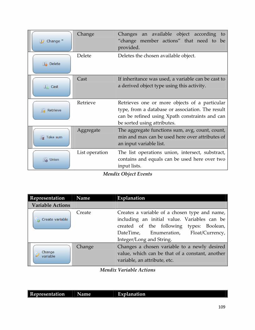
109
Change Changes an available object according to
‚change member actions‛ that need to be
provided.
Delete Deletes the chosen available object.
Cast If inheritance was used, a variable can be cast to
a derived object type using this activity.
Retrieve Retrieves one or more objects of a particular
type, from a database or association. The result
can be refined using Xpath constraints and can
be sorted using attributes.
Aggregate The aggregate functions sum, avg, count, count,
min and max can be used here over attributes of
an input variable list.
List operation The list operations union, intersect, substract,
contains and equals can be used here over two
input lists.
Mendix Object Events
Representation Name Explanation
Variable Actions
Create Creates a variable of a chosen type and name,
including an initial value. Variables can be
created of the following types: Boolean,
DateTime, Enumeration, Float/Currency,
Integer/Long and String.
Change Changes a chosen variable to a newly desired
value, which can be that of a constant, another
variable, an attribute, etc.
Mendix Variable Actions
Representation Name Explanation

110
Client Actions
Show form Shows a specified form to the user, either
replacing the current form (Content) or opening
a new one (Popup / Blocking popup, the latter
preventing the user to interact with anything on
the page except for the popup).
Show message Shows a customizable message to the user, of
the type information, warning or error. The
message can be ‚Blocking‛ if needed.
Mendix Client Actions
There is an special activity, a looped activity which iterates over a list of objects (which
is the input parameter for the loop), performing the activities which are presented
within the loop square. A looped activity can contain all elements used in micro flows,
except for start and end events.
Looped Activity
Representation Name Explanation
Gateways
Exclusive split Basically a XOR-split that splits the flow
according to conditions provided in the split.
This condition can be based on a variable, an
expression or a business rule.
Exclusive merge Joins two or more flows back into one (XOR-
join) when the unique actions after the split are
over.

111
Inheritance split Allows for the use of ‚super object‛ properties
by sub objects. The split checks the input and
chooses the proper outgoing line according to
object type. In case it was a sub object, a cast
action is required after the split.
Mendix Gateways
Representation Name Explanation
Connecting
Objects
Sequence flow The micro flow is executed following the
sequence flow arrows, which determine the
order in which actions are executed.
Association Associations are used to connect annotations to
any element in a micro flow except for the start
event.
Mendix Connecting Objects
Representation Name Explanation
Artifacts
Parameter Specifies the required input variable(s) for the
microflow, of a specified type and name. A
microflow can have zero to many input objects.
Annotation Comments that can be attached to elements in a
microflow using an association. Annotations
have no impact on the execution and are
intended to improve understanding where
needed.
Mendix Artifacts

112
Appendix F
-<<K>>name:string
-clientIP:string
-serverPort:int
-start:Moment
-durationHours:int
-note:string
-nDisconnectedPolls:int
VM usage
+active
+fail
+pending
+history
«enumeration»
VMU state1 state *
-<<NN>>name:string
-deployedToday:boolean
-maxduration:int
-minMemory:int
-frozenAt:moment
-failNote:string
-organizerApproved:boolean
-ownerApproved:boolean
-...
Image
+pending
+active
+history
+failed
+stopRequested
«enumeration»
Destroy RQ
+...
+Linux
+WindowsXP
«enumeration»
OS type
1 State*
1
*
1
*
-<<K>>email:string
-<<NN>>password:string
-rangboomID:string
-rsyncpassword:string
-emailVerified:boolean
User
-<<K>>dnsName
-ipAddr:string
-capacity:int
-nDisconnectedPollsBeforeAbort:int
-...
Host
-port:int
Reachable port
**
-hostAdminApproved:boolean
Internet Access
*
1 User
*
1 Host1 usedBy*
*
1 requestedBy
*
1 owner
Organizer Bundle admin Host admin
*
1 admin
-<<K>>name:string
Group
1
*
*
*
-organizerApproved:boolean
Registered for
-group1
-*
*
1
-*
*
1 source
* target
-<<NN>>name:string
VDI list*
1 Image
1 createdBy
*
Conceptual data model
Domain model

113
Appendix G
MyMutableVDIs:
-Mutable VDIS:
NewSession links
Discard request links
Publish image links
Discard image links
Details image links
Transfer image links
Transfer
Ownership:
-VDI link
-Transfer Button
Click Transfer
Home:
-username box
-password box
-login button
-Bundle links
-requests for review (with
approve/deny button)
<<includes>>
MyMutableVDIs
LookupImage:
-Other images link
-VDI link
Click VDI
Click Transfer
(success)
Message
‘succed’
Click Transfer
(failed)
Index:
-Home button
-Request Session button
-Log off button
-Login button
<<includes>>
Home
Message
‘error’
Screen-flow ‘Transfer Ownership’ use case for PHP
Message
‘error’
Index:
-Mutable Images grid
-Welcome grid
-Sessions grid
...
Mutable Images:
-Mutable VDIs:
NewSession link
Publish image link
Discard image link
Details image link
Transfer image link
<<contains>>
Mutable Images grid
Menu bar:
-Administration links
-General links
-Demonstrator links
-Host links
-Organizer links
Control bar:
-Home button
-Reload button
-Back button
-Forward button
-Log-out button
Transfer Ownership:
-VDI link
-User combo box
-Transfer button
-Cancel button
Click Transfer
LookupImage:
-VDIs:
VDI links
VDI shortname
links
-Search button
Click VDI
Click Transfer
(success)
Message
‘success’
Click cancel
Click Transfer
(failed)
Screen-flow ‘Transfer Ownership’ use case for Mendix

114
Home:
-username box
-password box
-login button
-Bundle links
-requests for review (with
approve/deny button)
Index:
-Home button
-Request Session button
-Log off button
-Login button
<<includes>>
Home
Menu:
-find images button
-manage your lists button
-upload files button
-modify password button
-bundle access button
-mutable clon button
-view banners button
-update disk own button
-reg new disk button
-update disk button
-manage regs button
-manage internet button
-check server button
-view all mutima button
-gen rep scripts button
-register new vdi
-add bundle button
<<includes>>
eindex
Update disk:
-Group links
-All groups link
-VDIs:
Image name box
Short name box
Group combo box
MAC box
IDE controller box
Owner combo box
IOAPIC link
IOAPIC combo box
Description box
Update button
Take ownership and make mutable link
Click update disk
Click take ownership…
(success)
Message
‘success’
Click take ownership…
(failed)
Message
‘error’
Click Group
Click All groups
Click Update
Screen-flow ‘Take Ownership and Make Mutable’ use case for PHP
Menu bar:
-Administration links
-General links
-Demonstrator links
-Host links
-Organizer links
Control bar:
-Home button
-Reload button
-Back button
-Forward button
-Log-out button
Update disk:
-Group links
-All groups link
-VDIs:
IOAPIC radio buttons
Modify button
Take ownership and
make mutable link
Click Update Disk
(from Organizer links)
Click All groups
Click Group
Modify Virtual
Disk Image
Click Modify
Index:
-Mutable Images grid
-Welcome grid
-Sessions grid
...
Click take ownership…
(failed)
Message
‘error’
Click take ownership…
(success)
Message
‘success’
Screen-flow ‘Take Ownership and Make Mutable’ use case for PHP
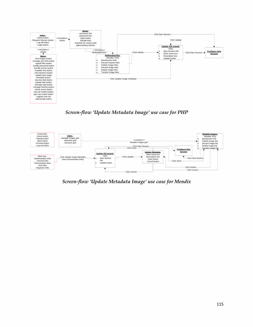
115
Home:
-username box
-password box
-login button
-Bundle links
-requests for review (with
approve/deny button)
Index:
-Home button
-Request Session button
-Log off button
-Login button
<<includes>>
Home
Menu:
-find images button
-manage your lists button
-upload files button
-modify password button
-bundle access button
-mutable clon button
-view banners button
-update disk image
metadata button
-reg new disk button
-update disk button
-manage regs button
-manage internet button
-check server button
-view all mutima button
-gen rep scripts button
-register new vdi
-add bundle button
<<includes>>
eindex Click Details
Click Update Image metadata
Update VDI owned:
-VDIs:
New Session link
Short name box
Description box
Update button
Click Update
Configure New
SessionClick New Session
MyMutableVDIs:
-Mutable VDIS:
NewSession links
Discard request links
Publish image links
Discard image links
Details image links
Transfer image links
<<includes>>
MyMutableVDIs
Click New Session
Screen-flow ‘Update Metadata Image’ use case for PHP
Menu bar:
-Administration links
-General links
-Demonstrator links
-Host links
-Organizer links
Control bar:
-Home button
-Reload button
-Back button
-Forward button
-Log-out button
Update VDI owned:
-VDIs:
New Session
link
Update button
Click Update Image Metadata
(from Demonstrator links)
Update Metadata:
-Short name box
-Description box
-Save button
-Cancel button
Click Update
Click Save
Click Cancel
Configure New
Session
Click New Session
Index:
-Mutable Images grid
-Welcome grid
-Sessions grid
...
Mutable Images:
-Mutable VDIs:
NewSession link
Publish image link
Discard image link
Details image link
Transfer image link
<<contains>>
Mutable Images grid
Click Details
Click Cancel
Click Save
Click New Session
Screen-flow ‘Update Metadata Image’ use case for Mendix
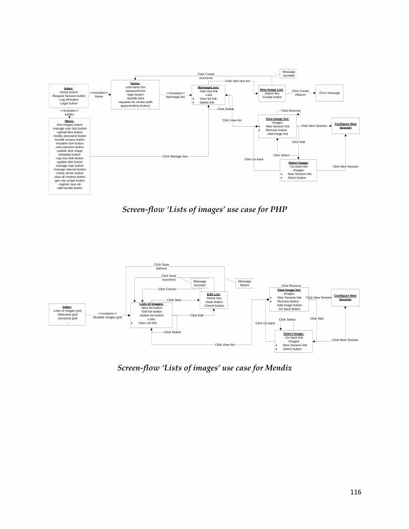
116
Home:
-username box
-password box
-login button
-Bundle links
-requests for review (with
approve/deny button)
Index:
-Home button
-Request Session button
-Log off button
-Login button
<<includes>>
Home
Menu:
-find images button
-manage your lists button
-upload files button
-modify password button
-bundle access button
-mutable clon button
-view banners button
-update disk image
metadata button
-reg new disk button
-update disk button
-manage regs button
-manage internet button
-check server button
-view all mutima button
-gen rep scripts button
-register new vdi
-add bundle button
<<includes>>
eindex
Click Manage lists
MyImageLists:
-Add new link
-Lists
View list link
Delete link
<<includes>>
MyImageLists
Click Add new list
New Image List:
-Name box
-Create button
Click Create
(success)
Message
‘success’
Click Create
(failure)Error message
Click Delete
View Image list:
-Images:
New Session link
Remove button
-Add image link
Click View list
Configure New
SessionClick New Session
Click Remove
Select Image:
-Go back link
-Images:
New Session link
Select button
Click New Session
Click Select
Click Go back
Click Add
Screen-flow ‘Lists of images’ use case for PHP
Index:
-Lists of images grid
-Welcome grid
-Sessions grid
...
Lists of images:
-New list button
-Edit list button
-Delete list button
-Lists:
View List link
<<contains>>
Mutable Images grid
Click New
Edit List:
-Name box
-Save button
-Cancel button
Click Cancel
Click Save
(success)
Click Save
(failure)
Message
‘success’
Message
‘failure’
Click Edit
Click Delete
View Image list:
-Images:
New Session link
Remove button
-Add image button
-Go back button
Click View list
Configure New
SessionClick New Session
Click Remove
Select Image:
-Go back link
-Images:
New Session link
Select button
Click New Session
Click SelectClick Go back
Click Add
Screen-flow ‘Lists of images’ use case for Mendix

117
Home:
-username box
-password box
-login button
-Bundle links
-requests for review (with
approve/deny button)
-All your images link
Index:
-Home button
-Request Session button
-Log off button
-Login button
<<includes>>
Home
Menu:
-find images button
-manage your lists button
-upload files button
-modify password button
-bundle access button
-mutable clon button
-view banners button
-update disk image
metadata button
-reg new disk button
-update disk button
-manage regs button
-manage internet button
-check server button
-view all mutima button
-gen rep scripts button
-register new vdi
-add bundle button
<<includes>>
eindex
Lookup Image (owner):
-Find other images link
-Images:
New Session link
Update metadata link
Click
All your images
Update MetadataConfigure New
Session
Click
Update metadata
Click
New Session
Lookup Image(search):
-Image name box (.vdi)
-Image name box (readable)
-Description box
-Bundle name box
-Own images checkbox
-LookupImage button
Lookup Image(results):
-Find other images link
-Images(normal):
New Session link
-Images(own):
New Session link
Update metadata link
Click
Find other images
Click
LooikupImage
Click
Update metadata
Click
New Session
Click
Find other images
Click
Bundle
Click
Find images
Screen-flow ‘Search Images’ use case for PHP
Index:
-All your images link
-Welcome grid
-Sessions grid
...
Menu bar:
-Administration links
-General links
-Demonstrator links
-Host links
-Organizer links
Control bar:
-Home button
-Reload button
-Back button
-Forward button
-Log-out button
Lookup Image (owner):
-Find other images link
-Images:
New Session link
Edit metadata link
Click
All your imagesUpdate Metadata
Configure New
Session
Click
Update metadata
Click
New Session
Lookup Image:
-Search button
-Image name box (.vdi)
-Image name box (readable)
-Description box
-Bundle name box
-Images(normal):
New Session link
-Images(own):
New Session link
Update metadata linkClick
Find other images
Click
New Session
Click
Update metadata
Home Form:
-Email box
-Password box
-Forgot pwd link
-Login button
-Request new account
link
-Bundle links
Lookup Image:
-Find other images link
-Images:
New Session link
Click bundle
Click
Find other images
Screen-flow ‘Search Images’ use case for Mendix
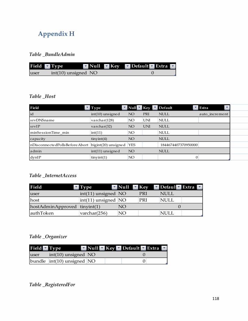
118
Appendix H
Table _BundleAdmin
Field Type Null Key Default Extra
user int(10) unsigned NO 0
Table _Host
Field Type Null Key Default Extra
id int(10) unsigned NO PRI NULL auto_increment
srvDNSname varchar(128) NO UNI NULL
srvIP varchar(32) NO UNI NULL
minSessionTime_min int(11) NO NULL
capacity tinyint(4) NO NULL
nDisconnectedPollsBeforeAbort bigint(20) unsigned YES 1844674407370950000
admin int(11) unsigned NO NULL
dynIP tinyint(1) NO 0
Table _InternetAccess
Field Type Null Key Default Extra
user int(11) unsigned NO PRI NULL
host int(11) unsigned NO PRI NULL
hostAdminApproved tinyint(1) NO 0
authToken varchar(256) NO NULL
Table _Organizer
Field Type Null Key Default Extra
user int(10) unsigned NO 0
bundle int(10) unsigned NO 0
Table _RegisteredFor

119
Field Type Null Key Default Extra
user int(10) unsigned NO NULL
bundle int(10) unsigned NO NULL
approved tinyint(1) NO 0
authToken varchar(256) NO NULL
Table _RWConfig
Field Type Null Key Default Extra
id int(10) unsigned NO PRI NULL auto_increment
ownerApproval enum('req','ok','nok') NO req
adminApproval enum('req','ok','nok') NO req
srcVDI int(10) unsigned NO 0
trgVDI int(10) unsigned NO 0
requestedBy int(10) unsigned NO 0
failNote varchar(256) YES NULL
destroyRQ
enum('none','discard','makeImm
utable','makeNormal') YES none
Table _User
Field Type Null Key Default Extra
id int(11) unsigned NO PRI NULL auto_increment
email varchar(320) NO NULL
password varchar(32) NO NULL
rangboomid varchar(64) YES NULL
rsyncpassword varchar(64) YES NULL
resetToken varchar(255) YES NULL
Table _UserAccountRQ
Field Type Null Key Default Extra
username varchar(320) NO NULL
password varchar(32) NO NULL
authToken varchar(256) NO NULL
bundle int(11) unsigned NO NULL
authTokenUSR varchar(256) NO NULL

120
Table _ValidServerPorts
Field Type Null Key Default Extra
host int(10) unsigned NO PRI 0
port smallint(5) unsigned NO PRI 0
Table _VDI
Field Type Null Key Default Extra
id int(10) unsigned NO PRI NULL auto_increment
name varchar(256) NO NULL
osType varchar(32) YES NULL
deployedToday tinyint(1) NO 1
host int(10) unsigned NO 0
owningUser int(10) unsigned NO 0
bundle int(10) unsigned NO 0
idecontroller varchar(16) NO PIIX4
mac varchar(12) NO auto
maxduration int(11) unsigned NO 0
minMemory int(11) NO 1024
description varchar(6000) YES No description given
shortName varchar(128) YES NULL
infoURL varchar(2048) YES NULL
targetBundle int(10) unsigned YES NULL
threeDsupport tinyint(1) NO 0
ioapic tinyint(1) NO 0
Table _VDIBundle
Field Type Null Key Default Extra
id int(10) unsigned NO PRI NULL auto_increment
name varchar(256) NO UNI NULL
isPublic tinyint(1) NO 1
Table _VDIList

121
Field Type Null Key Default Extra
id int(10) unsigned NO PRI NULL auto_increment
name varchar(255) NO NULL
createdBy int(10) unsigned NO NULL
Table _VDIListElements
Field Type Null Key Default Extra
list int(10) unsigned NO NULL
seqNum int(10) unsigned NO PRI NULL auto_increment
vdiName varchar(255) NO NULL
Table _VMUsage
Field Type Null Key Default Extra
vmName varchar(256) NO NULL
clientIP varchar(320) NO NULL
srvPort smallint(5) unsigned NO NULL
start datetime NO NULL
duration_hours bigint(20) NO NULL
state
enum('pending','active','history','
failed','stopRequested') YES NULL
vdi int(10) unsigned NO NULL
usedBy int(10) unsigned NO 0
note varchar(256) YES NULL
nDisconnectedPolls bigint(20) unsigned YES 0
memory int(11) NO 1024
stoppedReal datetime NO NULL

122
Appendix I
Screens for Update Image Metadata in PHP and Mendix solutions

123
Appendix J
Skelta
Skelta BPM is a BPM workflow software that is built on Microsoft .NET, XML, and Web
services technologies. Skelta software enables business users and developers to design
and deploy BPM workflow applications using tools with which they are already
familiar [99].
Positive Negative
Skelta has tight integration with
Microsoft products such as Office,
SharePoint, other technologies
(BizTalk,.NET)
The user is able to add human
activities into the microflow to
make it more like a workflow.
Provides complete history and
audit trail of user interactions
Support for clustering of servers
and load balancing
It is possible to set KPI's and SLA's
Skelta is aimed at Microsoft
technology.
No custom applications or widgets
to add.
Positive and Negative with Skelta
Bizagi
Bizagi is a BPM solution that will enable to model, automate, execute and improve
business processes through a graphic environment and without the need of
programming. The platform consists of three tools; Bizagi Process Modeler (diagram
and documentation module), Bizagi Studio (construction module) and Bizagi BPM
Server (execution and control module) that are used to manage the complete process
lifecycle.
Positive Negative
It allows you to easily model
business processes with the BPMN
notation
The documentation needs to be
improved
Does not support simulation or

124
Easy to use for beginners and
suitable for presentations
Java-based and Windows-based
versions.
animation
Less suitable for analytics or larger
projects (slower with large number
of models).
Just support SQL and Oracle for
database
Positive and Negative aspects of Bizagi
OutSystems
The Agile Platform of OutSystems enables companies to create, modify
and maintain entrepreneurial applications that can be changed during each stage of its l
ife cycle [100].
Positive Negative
Cloud services and mobile apps
Based on .NET and Java
Continuous integration: the
processes can immediately be tested
by supplier and customer after the
implementation
Since there is no code, it is not
possible to reuse the models in
another tool.
Positive and Negative aspects of OutSystems