Embed Size (px)
Citation preview
EiconCard S90for PCI-Compatible Bus
Installation Guide203-187-01

e is
as ns at
ay
ion
First Edition (March 1998)Eicon, EiconCard, and EiconCard S90 are trademarks of Eicon Technology Corporation.
Changes are periodically made to the information herein; these changes will bincorporated into new editions of the publication. Eicon Technology may makeimprovements and/or changes in the products and/or programs described in thpublication at any time.
A product comment form is provided at the back of this publication. If the form hbeen removed, address your comments to the attention of Corporate Publicatiothe address shown below, or by electronic mail to [email protected]. Eicon Technology may use or distribute whatever information you supply in any wit believes appropriate without incurring any obligations to you.
Copyright © 1998 Eicon Technology Corporation. All rights reserved, includingthose to reproduce this publication or parts thereof in any form without permissin writing from Eicon Technology Corporation.
Eicon Technology Corporation9800 Cavendish Blvd.Montreal, QuebecCanada, H4M 2V9
.. 5
.. 6
... 7
.. 8
... 9
.. 10
.. 12. 14.. 16.. 18.. 20
21
22
25
Table of ContentsIntroduction..........................................................................
Installing the EiconCard S90 ...............................................
Selecting an Interface..........................................................
Interface Specifications........................................................Cable Construction Information .........................................................The V.24 Interface..............................................................................The V.35 Interface..............................................................................The EIA-530 Interface ........................................................................The V.36/RS-449 Interface.................................................................The X.21 Interface .............................................................................Back-to-Back Connections ................................................................
Technical Specifications ......................................................
International Regulatory Information ..................................
Limited Warranty.................................................................

s 5, ps.
,
t
0, ing
ted .
ng
IntroductionThe EiconCard S90 is a PCI Plug-and-Play (PnP) card that offerX.25 connectivity through a high-speed port (supporting V.24, V.3EIA-530, V.36/RS-449, or X.21 interfaces) at speeds of up to 2 Mb
Note The EiconCard S90 also supports protocols such as SDLCPPP, and Frame Relay.
Hardware Features
The EiconCard S90 features a 25 MHz Motorola 68302 microprocessor with 1 MB of RAM and 1 MB of FLASH memory. Ihas one independent Very High-Speed Interface (VHSI) port, supporting full duplex communications over a V.24, V.35, EIA-53V.36/RS-449, or X.21 interface at speeds of up to 2 Mbps (dependon the type of interface selected).
Ease of Use
The EiconCard S90 features automatic interface selection. The intelligent controller on the card detects the type of cable connecto the VHSI port and automatically selects the matching interface
About this ManualThis guide describes how to install the EiconCard S90 in any computer with an IBM PC-compatible PCI bus. It covers the following topics:
• Installing the card and connecting cables.
• Interpreting the status light on the card.
For instructions on setting up communications protocols and usiapplications, consult the documentation provided with your networking software.
EiconCard S90 Installation Guide 5
u N,
r of
ing ble.
90
ork me
Installing the EiconCard S90The steps below describe how to install the EiconCard S90. If yowant the EiconCard S90 to be available to multiple users on a LAinstall it in the PC that will function as a gateway for the LAN.
1 Prepare the PC
Turn off the PC and disconnect its power cable. Remove the covethe PC according to the instructions that came with it.
2 Install the EiconCard S90
Insert the EiconCard S90 into any available PCI port. Secure theEiconCard S90 to the chassis of the PC using the bracket-retainscrew. Reinstall the cover of the PC and reconnect the power ca
3 Test the EiconCard S90
The application software that you purchased with the EiconCard Sincludes a test program to verify the card’s integrity. Consult the documentation supplied with this software for details.
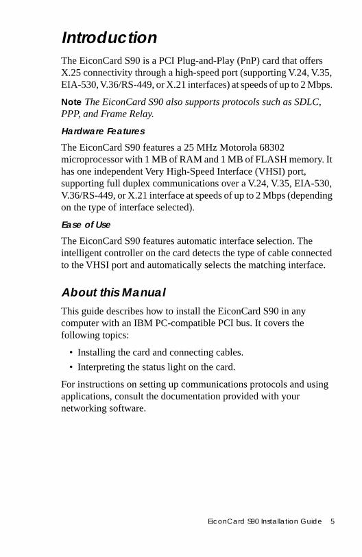
4 Configure the EiconCard S90
Before you can use the EiconCard S90, you must configure it to wwith your communications software. The documentation which cawith this software contains complete instructions on how to configure the card.
During configuration, note that the LED flashes. This feature is useful when more than one card is installed in the same PC.
Consult the documentation which came with your networking software for more information about the LED.
Figure 1. End Bracket
Port
LED
6 EiconCard S90 Installation Guide
ata s:
d.
SI ogy e
the
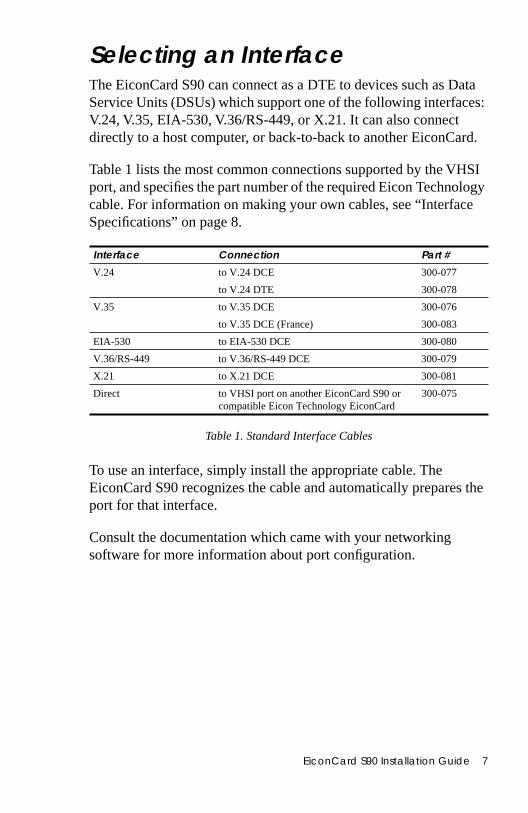
Selecting an InterfaceThe EiconCard S90 can connect as a DTE to devices such as DService Units (DSUs) which support one of the following interfaceV.24, V.35, EIA-530, V.36/RS-449, or X.21. It can also connect directly to a host computer, or back-to-back to another EiconCar
Table 1 lists the most common connections supported by the VHport, and specifies the part number of the required Eicon Technolcable. For information on making your own cables, see “InterfacSpecifications” on page 8.
Table 1. Standard Interface Cables
To use an interface, simply install the appropriate cable. The EiconCard S90 recognizes the cable and automatically preparesport for that interface.
Consult the documentation which came with your networking software for more information about port configuration.
Interface Connection Part #
V.24 to V.24 DCE 300-077
to V.24 DTE 300-078
V.35 to V.35 DCE 300-076
to V.35 DCE (France) 300-083
EIA-530 to EIA-530 DCE 300-080
V.36/RS-449 to V.36/RS-449 DCE 300-079
X.21 to X.21 DCE 300-081
Direct to VHSI port on another EiconCard S90 or compatible Eicon Technology EiconCard
300-075
EiconCard S90 Installation Guide 7
HSI
, to t.
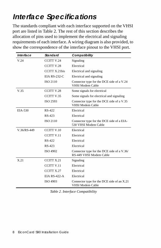
Interface SpecificationsThe standards compliant with each interface supported on the Vport are listed in Table 2. The rest of this section describes the allocation of pins used to implement the electrical and signaling requirements of each interface. A wiring diagram is also providedshow the correspondence of the interface pinout to the VHSI por
Table 2. Interface Compatibility
Interface Standard Compatibility
V.24 CCITT V.24 Signaling
CCITT V.28 Electrical
CCITT X.21bis Electrical and signaling
EIA RS-232-C Electrical and signaling
ISO 2110 Connector type for the DCE side of a V.24 VHSI Modem Cable
V.35 CCITT V.28 Some signals for electrical
CCITT V.35 Some signals for electrical and signaling
ISO 2593 Connector type for the DCE side of a V.35 VHSI Modem Cable
EIA-530 RS-422 Electrical
RS-423 Electrical
ISO 2110 Connector type for the DCE side of a EIA-530 VHSI Modem Cable
V.36/RS-449 CCITT V.10 Electrical
CCITT V.11 Electrical
RS-422 Electrical
RS-423 Electrical
ISO 4902 Connector type for the DCE side of a V.36/ RS-449 VHSI Modem Cable
X.21 CCITT X.21 Signaling
CCITT V.11 Electrical
CCITT X.27 Electrical
EIA RS-422-A Electrical
ISO 4903 Connector type for the DCE side of an X.21 VHSI Modem Cable
8 EiconCard S90 Installation Guide
the
he ll at its
ill
tor. e
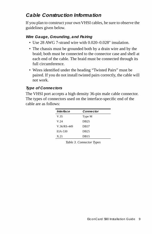
Cable Construction InformationIf you plan to construct your own VHSI cables, be sure to observeguidelines given below.
Wire Gauge, Grounding, and Pairing• Use 28 AWG 7-strand wire with 0.020–0.028" insulation.
• The chassis must be grounded both by a drain wire and by tbraid; both must be connected to the connector case and sheeach end of the cable. The braid must be connected throughfull circumference.
• Wires identified under the heading “Twisted Pairs” must be paired. If you do not install twisted pairs correctly, the cable wnot work.
Type of ConnectorsThe VHSI port accepts a high density 36-pin male cable connecThe types of connectors used on the interface-specific end of thcable are as follows:
Table 3. Connector Types
Interface Connector
V.35 Type M
V.24 DB25
V.36/RS-449 DB37
EIA-530 DB25
X.21 DB15
EiconCard S90 Installation Guide 9
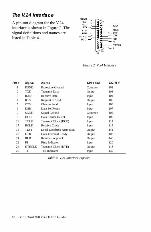
The V.24 InterfaceA pin-out diagram for the V.24 interface is shown in Figure 2. Thesignal definitions and names are listed in Table 4.
10 EiconCard S90 Installation Guide
Figure 2. V.24 Interface
PG ND
RXDRTS
1
RIDCD
SG ND
TXD
TCLK
CTSDSR
DTR
DTECLK
TEST
RLB
TI25
RCLK
14
13
Table 4. V.24 Interface Signals
Pin # Signal Name Direction CCITT #1 PGND Protective Ground Common 101
2 TXD Transmit Data Output 103
3 RXD Receive Data Input 104
4 RTS Request to Send Output 105
5 CTS Clear to Send Input 106
6 DSR Data Set Ready Input 107
7 SGND Signal Ground Common 102
8 DCD Data Carrier Detect Input 109
15 TCLK Transmit Clock (DCE) Input 114
17 RCLK Receive Clock Input 115
18 TEST Local Loopback Activation Output 141
20 DTR Data Terminal Ready Output 108
21 RLB Remote Loopback Output 140
22 RI Ring Indicator Input 125
24 DTECLK Transmit Clock (DTE) Output 113
25 TI Test Indicator Input 142
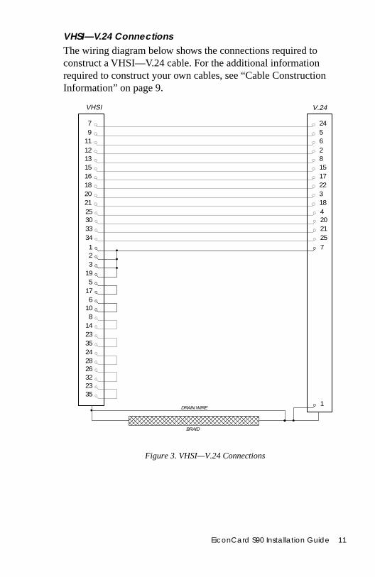
VHSI—V.24 ConnectionsThe wiring diagram below shows the connections required to construct a VHSI—V.24 cable. For the additional information required to construct your own cables, see “Cable Construction Information” on page 9.
Figure 3. VHSI—V.24 Connections
7
VHSI V.24
2335
DRAIN WIRE1
BRAID
7 249 5
11 612 213 815 1516 1718 2220 321 1825 430 2033 2134 25123
195
176
10
23352428
814
2632
EiconCard S90 Installation Guide 11
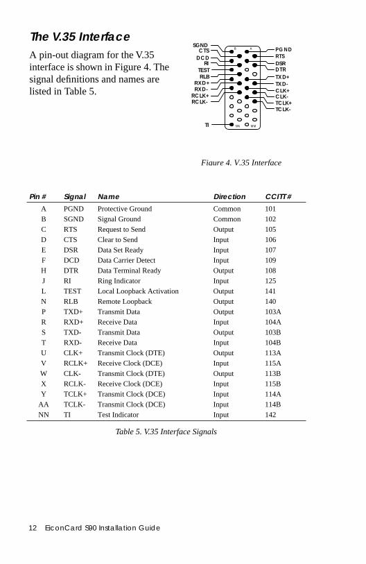
The V.35 InterfaceA pin-out diagram for the V.35 interface is shown in Figure 4. Thesignal definitions and names are listed in Table 5.
12 EiconCard S90 Installation Guide
Figure 4. V.35 Interface
P G ND
RXD+
R T SRI
D CD
SGND
TX D+
CTS
DSRD T R
CLK+
TESTRLB
TI
RCLK+
TXD-RXD-
CLK-RCLK- TCLK+
TCLK-
A
NN MM
B
Table 5. V.35 Interface Signals
Pin # Signal Name Direction CCITT #
A PGND Protective Ground Common 101
B SGND Signal Ground Common 102
C RTS Request to Send Output 105
D CTS Clear to Send Input 106
E DSR Data Set Ready Input 107
F DCD Data Carrier Detect Input 109
H DTR Data Terminal Ready Output 108
J RI Ring Indicator Input 125
L TEST Local Loopback Activation Output 141
N RLB Remote Loopback Output 140
P TXD+ Transmit Data Output 103A
R RXD+ Receive Data Input 104A
S TXD- Transmit Data Output 103B
T RXD- Receive Data Input 104B
U CLK+ Transmit Clock (DTE) Output 113A
V RCLK+ Receive Clock (DCE) Input 115A
W CLK- Transmit Clock (DTE) Output 113B
X RCLK- Receive Clock (DCE) Input 115B
Y TCLK+ Transmit Clock (DCE) Input 114A
AA TCLK- Transmit Clock (DCE) Input 114B
NN TI Test Indicator Input 142
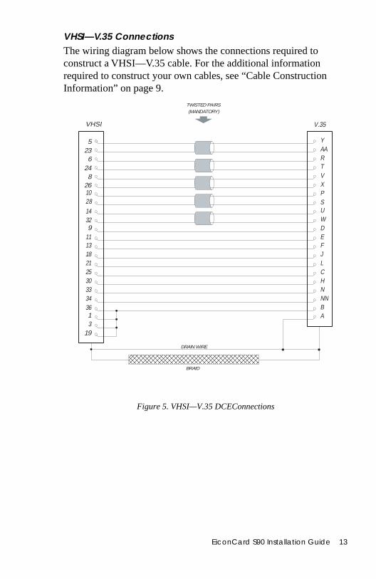
VHSI—V.35 ConnectionsThe wiring diagram below shows the connections required to construct a VHSI—V.35 cable. For the additional information required to construct your own cables, see “Cable Construction Information” on page 9.
Figure 5. VHSI—V.35 DCEConnections
VHSI V.35
DRAIN WIRE
5236
24
1028
8
U
26
W9 D
11 E13 F18 J21 L25 C30 H333436
BRAID
NNNBA
YAARTVXPS
TWISTED PAIRS(MANDATORY)
13
19
1432
EiconCard S90 Installation Guide 13
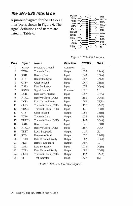
The EIA-530 InterfaceA pin-out diagram for the EIA-530 interface is shown in Figure 6. Thesignal definitions and names are listed in Table 6.
Pin # Signal Name D
1 PGND Protective Ground
14 EiconCard S90 Installation Guide
Figure 6. EIA-530 Interface
TRXC+
RTXC+
DTR+
CL K+
RXD-
RTS-
DCD-
TXD-
TRXC-
RTXC-
CTS-
DSR-DTR-
TEST
RLB
TI
CLK-
PGND
RXD+RTS+
1
DCD+SG ND
TXD+
CTS+DSR+
2513
14
irection CCITT # EIA #
Common 101 -
Table 6. EIA-530 Interface Signals
2 TXD+ Transmit Data Output 103A BA(A)
3 RXD+ Receive Data Input 104A BB(A)
4 RTS+ Request to Send Output 105A CA(A)
5 CTS+ Clear to Send Input 106A CB(A)
6 DSR+ Data Set Ready Input 107A CC(A)
7 SGND Signal Ground Common 102B AB
8 DCD+ Data Carrier Detect Input 109A CF(A)
9 RTXC- Receive Clock (DCE) Input 115B DD(B)
10 DCD- Data Carrier Detect Input 109B CF(B)
11 CLK- Transmit Clock (DTE) Output 113B DA(B)
12 TRXC- Transmit Clock (DCE) Input 114B DB(B)
13 CTS- Clear to Send Output 106B CB(B)
14 TXD- Transmit Data Output 103B BA(B)
15 TRXC+ Transmit Clock (DCE) Input 114A DB(A)
16 RXD- Receive Data Input 104B BB(B)
17 RTXC+ Receive Clock (DCE) Input 115A DD(A)
18 TEST Local Loopback Output 141A LL
19 RTS- Request to Send Output 105B CA(B)
20 DTR+ Data Terminal Ready Output 108A CD(A)
21 RLB Remote Loopback Output 140A RL
22 DSR- Data Set Ready Input 107B CC(B)
23 DTR- Data Terminal Ready Output 108B CD(B)
24 CLK+ Transmit Clock (DTE) Output 113A DA(A)
25 TI Test Indicator Input 142A TM
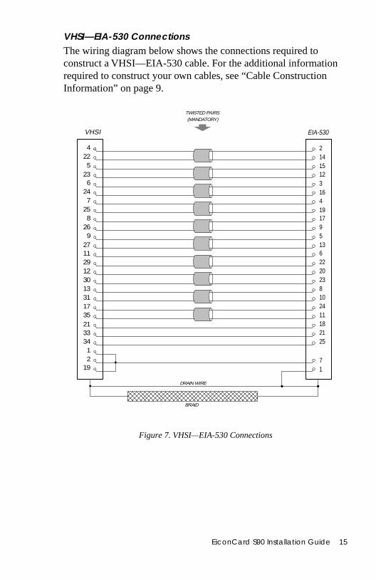
VHSI—EIA-530 ConnectionsThe wiring diagram below shows the connections required to construct a VHSI—EIA-530 cable. For the additional informationrequired to construct your own cables, see “Cable Construction Information” on page 9.
Figure 7. VHSI—EIA-530 Connections
VHSI EIA-530
DRAIN WIRE
4225
236
247
258 17
26 99 5
27 1311 629 2212 2030 2313 831173521
213334
BRAID
10241118
25
2141512316419
TWISTED PAIRS(MANDATORY)
7
12
19 1
EiconCard S90 Installation Guide 15
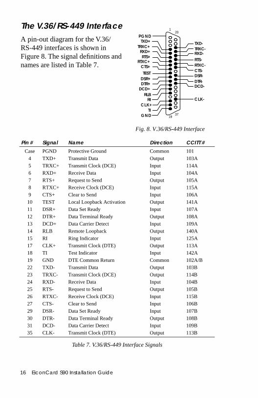
The V.36/RS-449 InterfaceA pin-out diagram for the V.36/RS-449 interfaces is shown in Figure 8. The signal definitions andnames are listed in Table 7.
16 EiconCard S90 Installation Guide
Fig. 8. V.36/RS-449 Interface
PG ND
RXD+RTS+
1
RI
DCD+
GND
TXD+TRXC+
RTXC+CTS+
DSR+DTR+
CL K+
RXD-RTS-
DCD-
TXD-TRXC-
RTXC-CTS-DSR-DTR-
TEST
RLB
TI
CLK-
3719
20
Table 7. V.36/RS-449 Interface Signals
Pin # Signal Name Direction CCITT #
Case PGND Protective Ground Common 101
4 TXD+ Transmit Data Output 103A
5 TRXC+ Transmit Clock (DCE) Input 114A
6 RXD+ Receive Data Input 104A
7 RTS+ Request to Send Output 105A
8 RTXC+ Receive Clock (DCE) Input 115A
9 CTS+ Clear to Send Input 106A
10 TEST Local Loopback Activation Output 141A
11 DSR+ Data Set Ready Input 107A
12 DTR+ Data Terminal Ready Output 108A
13 DCD+ Data Carrier Detect Input 109A
14 RLB Remote Loopback Output 140A
15 RI Ring Indicator Input 125A
17 CLK+ Transmit Clock (DTE) Output 113A
18 TI Test Indicator Input 142A
19 GND DTE Common Return Common 102A/B
22 TXD- Transmit Data Output 103B
23 TRXC- Transmit Clock (DCE) Output 114B
24 RXD- Receive Data Input 104B
25 RTS- Request to Send Output 105B
26 RTXC- Receive Clock (DCE) Input 115B
27 CTS- Clear to Send Input 106B
29 DSR- Data Set Ready Input 107B
30 DTR- Data Terminal Ready Output 108B
31 DCD- Data Carrier Detect Input 109B
35 CLK- Transmit Clock (DTE) Output 113B
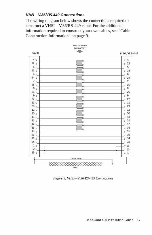
VHSI—V.36/RS-449 ConnectionsThe wiring diagram below shows the connections required to construct a VHSI—V.36/RS-449 cable. For the additional information required to construct your own cables, see “Cable Construction Information” on page 9.
Figure 9. VHSI—V.36/RS-449 Connections
VHSI V.36 / RS-449
DRAIN WIRE
4225
236
247
258 8
26 269 9
27 2711 1129 2912 1230 3013 133117351821 103334
20
BRAID
31173515
1418
422523624725
TWISTED PAIRS(MANDATORY)
1912
19 37
EiconCard S90 Installation Guide 17
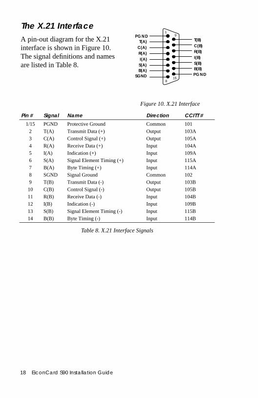
The X.21 InterfaceA pin-out diagram for the X.21 interface is shown in Figure 10. The signal definitions and names are listed in Table 8.
Pin # Signal Name
1/15 PGND Protective Ground
2 T(A) Transmit Data (+)
18 EiconCard S90 Installation Guide
Figure 10. X.21 Interface
PG ND1
T(A)C(A)R(A)I(A)
S(A)B(A)
SGND
T(B)C(B)R(B)I(B)S(B)B(B)PGND
158
9
Direction CCITT #
Common 101
Output 103A
Table 8. X.21 Interface Signals
3 C(A) Control Signal (+) Output 105A
4 R(A) Receive Data (+) Input 104A
5 I(A) Indication (+) Input 109A
6 S(A) Signal Element Timing (+) Input 115A
7 B(A) Byte Timing (+) Input 114A
8 SGND Signal Ground Common 102
9 T(B) Transmit Data (-) Output 103B10 C(B) Control Signal (-) Output 105B11 R(B) Receive Data (-) Input 104B12 I(B) Indication (-) Input 109B13 S(B) Signal Element Timing (-) Input 115B14 B(B) Byte Timing (-) Input 114B
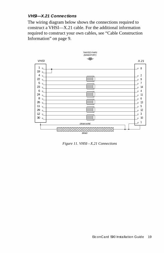
VHSI—X.21 ConnectionsThe wiring diagram below shows the connections required to construct a VHSI—X.21 cable. For the additional information required to construct your own cables, see “Cable Construction Information” on page 9.
Figure 11. VHSI—X.21 Connections
VHSI X.21
1194
225
236
248
261129 1212 330 10
8
1
97144116135
TWISTED PAIRS(MANDATORY)
2
DRAIN WIRE
BRAID
EiconCard S90 Installation Guide 19
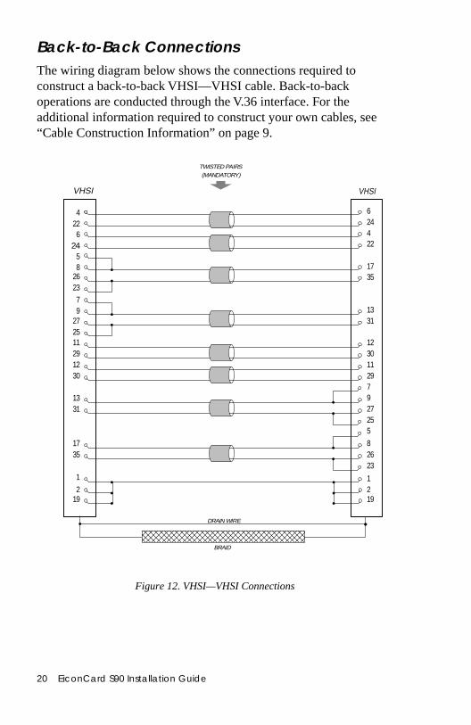
Back-to-Back ConnectionsThe wiring diagram below shows the connections required to construct a back-to-back VHSI—VHSI cable. Back-to-back operations are conducted through the V.36 interface. For the additional information required to construct your own cables, see“Cable Construction Information” on page 9.
Figure 12. VHSI—VHSI Connections
VHSI VHSI
DRAIN WIRE
4226
24
2623
58
1327 312511 1229 3012 1130 29
71331
BRAID
927255
624422
1735
TWISTED PAIRS(MANDATORY)
19
79
1735
82623
11
2192
20 EiconCard S90 Installation Guide
ve
Technical SpecificationsTechnical Data
• PCI bus compatible (32-bit slot)• Motorola 68302 CPU @ 25 MHz• 1 MB RAM• 1 MB FLASH memory
Hardware Installation• Automatic configuration of interrupt request level setting and I/O address• 32-bit I/O access
External Interface• One 36-pin female port
VHSI Port• One VHSI port connects to 36-pin high-density male connector• Support for V.24, V.35, EIA-530, and V.36/RS-449• X.21 with V.11 (X.27) signaling• Internal or external clocking (DTE or DCE) or split (transmit internal, recei
external)
Performance• 2 Mbps full duplex
Power Requirements• 1.0 A @ +5V• 45 mA @ +12V• 50 mA @ -12V
Environmental Requirements• Operating temperature: 0°C to 50°C• Operating humidity: 0 to 90% (non-condensing)• Barometric operating pressure: 86 to 106 kPascals• Maximum tolerance in power supply variation: +5% to -5%
EiconCard S90 Installation Guide 21

tion the
t may
n nt.
lass ed to
nergy rmful
sion er is ures:
ich
sions
International Regulatory InformationRegulatory Information for the USA:
FCC Warning
Declaration of ConformityWe:Eicon Technology Inc.2155 Chenault DriveSuite 503Carrollton, TexasUSA 750061-800-80-EICON(972) 417-5515Fax: (972) 417-5610Declare under our sole legal responsibility that the product to which this declararelates, are in conformity with Part 15 of the FCC Rules. Operation is subject tofollowing two conditions:(1) This device may not cause harmful interference, and
(2) this device must accept any interference received, including interference thacause undesired operation.
Warning: Changes or modifications to this unit not expressly approved by EicoTechnology Corporation could void the user's authority to operate the equipme
Note: This equipment has been tested and found to comply with the limits for a CB digital device, pursuant to Part 15 of the FCC Rules. These limits are designprovide reasonable protection against harmful interference in a residential installation. This equipment generates, uses and can radiate radio frequency eand, if not installed and used in accordance with the instructions, may cause hainterference to radio communications.
However, there is no guarantee that interference will not occur in a particular installation. If this equipment does cause harmful interference to radio or televireception, which can be determined by turning the equipment off and on, the usencouraged to try to correct the interference by one or more of the following meas
• Reorient or relocate the receiving antenna.• Increase the separation between the equipment and receiver.• Connect the equipment into an outlet on a circuit different from that to wh
the receiver is connected.• Consult the dealer or an experienced radio/TV technician for help.• This device requires a shielded cable to comply with the FCC Class B emis
limits. Use of unshielded interface cables is prohibited.
22 EiconCard S90 Installation Guide

ions dian
t les
found 1/
ints
ost, re e AL
sure it, and
nce ained er
Regulatory Information for CanadaThis digital apparatus does not exceed the Class B limits for radio noise emissfrom digital apparatus set out in the Radio Interference Regulations of the CanaDepartment of Communications.
Le présent appareil numérique n’émet pas de bruits radioélectriques dépassanlimites applicables aux appareils numériques de la classe B prescrites dans leRèglement sur le brouillage radioélectrique édicté par le ministère des Communications du Canada.
Regulatory Information for EuropeThis equipment displays the CE168 mark to show that it has been tested and to fully comply with the Terminal Equipment, EMC and Low Voltage Directives (9263/EEC, 89/336/EEC and 72/23/EEC, as amended by Directive 93/68/EEC).
Safety Status: SELVNo voltages within this equipment exceed SELV voltages. All interconnection poand ports are SELV.
User/Installer Instructions for the United KingdomEiconCard S90 Communications Board Important Safety Considerations When Installing Into A Host Computer SystemThe EiconCard S90 is a half-length PCI compatible card.
The EiconCard S90 is approved only for installation in an EN60950 approved hsurrounded by a minimum 2.5 mm air gap, and with host attachments which aeither type approved for such apparatus, or, if supplied after March 1, 1989, armarked with or supplied with a statement that the host is supplied under: GENERAPPROVAL NUMBER NS/G/1234/J/100003.
Installation Within A Spare Slot PositionIn order to comply with Safety Regulations particular care should be taken to enadequate separation between the EiconCard S90, the components mounted onany adjacent modules.
Except at the edge connector which plugs into the host’s expansion slot, clearaand creepage distances of X mm and Y mm, as listed in Table 9, must be maintbetween the EiconCard S90 card and other parts of the host including any othexpansion cards fitted.
ClearanceX mm
CreepageY mm
Voltage used or generated by other parts of the host or expansion card
Vrms or Vdc
2.0 2.4 (3.8) up to 50
2.6 3.0 (4.8) up to 125
4.0 5.0 (8.0) up to 250
4.0 6.4 (10.0) up to 300
EiconCard S90 Installation Guide 23
he ithin
shown ween points.
of wn by ceed
Table 9. Creepage Distances
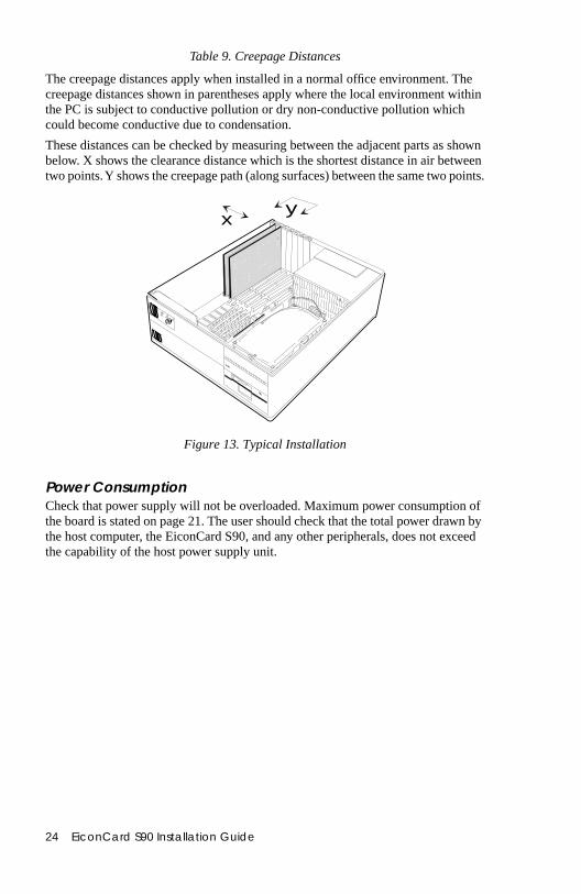
The creepage distances apply when installed in a normal office environment. Tcreepage distances shown in parentheses apply where the local environment wthe PC is subject to conductive pollution or dry non-conductive pollution which could become conductive due to condensation.
These distances can be checked by measuring between the adjacent parts asbelow. X shows the clearance distance which is the shortest distance in air bettwo points. Y shows the creepage path (along surfaces) between the same two
Figure 13. Typical Installation
Power ConsumptionCheck that power supply will not be overloaded. Maximum power consumptionthe board is stated on page 21. The user should check that the total power drathe host computer, the EiconCard S90, and any other peripherals, does not exthe capability of the host power supply unit.
xy
24 EiconCard S90 Installation Guide

d ail
al e
aced ty nt, pairs.
be ou also
of
sions
Limited WarrantyEicon Technology Corporation warrants to the original purchaser of this Eicon Technology Product that it is to be in good working order for a period of five (5) years from the date of purchase from Eicon Technology or an authorizeEicon Technology dealer. Should this Product, in Eicon Technology’s opinion, fto be in good working order at any time during this five year warranty period, Eicon Technology will, at its option, repair or replace this Product at no additioncharge except as set forth below. Repair parts and replacement Products will bfurnished on an exchange basis and will be either reconditioned or new. All replparts and Products become property of Eicon Technology. This Limited Warrandoes not include service to repair damage to the Product resulting from accidedisaster, misuse, abuse, or non-authorized alterations, modifications, and/or re
Products requiring Limited Warranty service during the warranty period shoulddelivered to Eicon Technology with proof of purchase. If the delivery is by mail, yagree to insure the Product or assume the risk of loss or damage in transit. Youagree to prepay shipping charges to Eicon Technology and to use the original shipping container or equivalent.
EICON TECHNOLOGY HEREBY DISCLAIMS ALL OTHER EXPRESSED AND IMPLIED WARRANTIES FOR THIS PRODUCT INCLUDING, BUT NOT LIMITED TO, THE WARRANTIES OF MERCHANTABILITY AND FITNESS FOR A PARTICULAR PURPOSE. Some jurisdictions do not allow the exclusionimplied warranties, so the above limitations may not apply to you.
IN NO EVENT WILL EICON TECHNOLOGY BE LIABLE IN ANY WAY TO THE USER FOR DAMAGES, INCLUDING ANY LOST PROFITS, LOST SAVINGS, OR OTHER INCIDENTAL OR CONSEQUENTIAL DAMAGES ARISING OUT OF THE USE OF, OR INABILITY TO USE, SUCH PRODUCT. Some jurisdictions do not allow the exclusion or limitation of incidental or consequential damages for consumer products, so the above limitations or exclumay not apply to you.
THIS WARRANTY GIVES YOU SPECIFIC LEGAL RIGHTS, AND YOU MAY ALSO HAVE OTHER RIGHTS WHICH MAY VARY FROM ONE JURISDICTION TO ANOTHER.
This Limited Warranty applies to hardware products only.
EiconCard S90 Installation Guide 25

duct.
Product Comment FormEiconCard S90
Installation Guide203-187-01
We value your comments. Please use the tables below to rate this pro
Name
Title
Company
Address
EiconCard S90Packaging Poor ➀ ➁ ➂ ➃ ➄ ➅ ➆ ➇ ➈ ➉ Excellent
Configuration Difficult ➀ ➁ ➂ ➃ ➄ ➅ ➆ ➇ ➈ ➉ Easy
Performance Poor ➀ ➁ ➂ ➃ ➄ ➅ ➆ ➇ ➈ ➉ Excellent
Workmanship Poor ➀ ➁ ➂ ➃ ➄ ➅ ➆ ➇ ➈ ➉ Excellent
Installation GuideAccuracy Low ➀ ➁ ➂ ➃ ➄ ➅ ➆ ➇ ➈ ➉ High
Organization Confusing ➀ ➁ ➂ ➃ ➄ ➅ ➆ ➇ ➈ ➉ Clear
Readability Difficult ➀ ➁ ➂ ➃ ➄ ➅ ➆ ➇ ➈ ➉ Easy
Presentation Poor ➀ ➁ ➂ ➃ ➄ ➅ ➆ ➇ ➈ ➉ Excellent
Please return this form to: Eicon Technology CorporationAttention: Corporate Publications9800 Cavendish Blvd.Montreal, Quebec, Canada H4M 2V9E-mail: [email protected]: (514) 745-5588Tel: (514) 745-5500

Printed in Canada


![S90 XS/S70 XS Editor VST Owner's Manual - Yamaha · Starting the S90 XS/S70 XS Editor VST S90 XS/S70 XS Editor VST Owner’s Manual 6 13. In Quick Set Up, select [1] or [2]. nFor](https://img.pdfslide.us/doc/110x75/5fa5d7be5c20e054d9711161/s90-xss70-xs-editor-vst-owners-manual-yamaha-starting-the-s90-xss70-xs-editor.jpg)