Embed Size (px)
Citation preview

1 23
Machine Vision and Applications ISSN 0932-8092Volume 25Number 2 Machine Vision and Applications (2014)25:489-500DOI 10.1007/s00138-013-0517-x
Structured light self-calibration withvanishing points
Radu Orghidan, Joaquim Salvi, MihaelaGordan, Camelia Florea & Joan Batlle

1 23
Your article is protected by copyright and
all rights are held exclusively by Springer-
Verlag Berlin Heidelberg. This e-offprint is
for personal use only and shall not be self-
archived in electronic repositories. If you wish
to self-archive your article, please use the
accepted manuscript version for posting on
your own website. You may further deposit
the accepted manuscript version in any
repository, provided it is only made publicly
available 12 months after official publication
or later and provided acknowledgement is
given to the original source of publication
and a link is inserted to the published article
on Springer's website. The link must be
accompanied by the following text: "The final
publication is available at link.springer.com”.

Machine Vision and Applications (2014) 25:489–500DOI 10.1007/s00138-013-0517-x
ORIGINAL PAPER
Structured light self-calibration with vanishing points
Radu Orghidan · Joaquim Salvi · Mihaela Gordan ·Camelia Florea · Joan Batlle
Received: 4 November 2012 / Revised: 29 March 2013 / Accepted: 26 April 2013 / Published online: 15 June 2013© Springer-Verlag Berlin Heidelberg 2013
Abstract This paper introduces the vanishing points toself-calibrate a structured light system. The vanishing pointspermit to automatically remove the projector’s keystoneeffect and then to self-calibrate the projector–camera sys-tem. The calibration object is a simple planar surface such asa white paper. Complex patterns and 3D calibrated objectsare not required any more. The technique is compared toclassic calibration and validated with experimental results.
Keywords Vanishing points · Self-calibration ·Pattern projection · Structured light · 3D reconstruction
1 Introduction
Multiple view-points are needed in non-intrusive machinevision applications that deal with metric measurements of thescene such as automatic inspection, 3D reconstruction, objectrecognition, robot guidance for target or self-localization,reverse engineering, process control and others. The tech-niques used for solving the shape acquisition problem can bedivided in two groups: passive and active. Passive techniquesare used for obtaining depth in a scene without any physi-cal interaction with the observed objects. The most commonpassive vision technique is the stereoscopy. A stereoscopicsystem, formed by two or more cameras, provides the nec-essary view-points and can be used for range estimation if
R. Orghidan · M. Gordan (B) · C. Florea · J. BatlleTechnical University of Cluj-Napoca, Cluj-Napoca, Romaniae-mail: [email protected]
R. Orghidane-mail: [email protected]
J. SalviUniversity of Girona, Girona, Spaine-mail: [email protected]
two conditions are accomplished: (1) the correspondencesbetween images are accurately determined and (2) the cam-eras are calibrated.
A crucial problem in stereovision is finding the corre-sponding features between several views of the same object.Geometric constraints, such as the ones introduced by theepipolar geometry [14], can be used for solving the corre-spondence problem yet at a high computational cost. More-over, the resolution of stereovision systems is relatively lowas it is dependent on the number of corresponding featureswhich is ultimately determined by the texture of the sceneobjects or by the existence of singular points. On the otherhand, active techniques have been introduced in order toenhance the capabilities of passive vision systems for findingcorrespondences. One of the most well-known techniques isthe structured light(SL) [10,25] which is an active stereovi-sion technique that alleviates the correspondence problem byilluminating the scene with a specially designed light pattern.The light reflected by the scene is measured and range esti-mation can be inferred. Concretely, the features projected bythe pattern onto the scene objects are uniquely identified andthe correspondences can be established at a high resolution.The first SL techniques were based on laser scanning [1]. Inthis case, the obtained images are easy to segment and thesemethods provide a high resolution. However, the speed andthe mechanical components of such configurations introduceunacceptable restrictions for some applications such as themeasuring of free moving objects. A more evolved modelwas introduced by the group of coded SL techniques. Thesetechniques are projecting bi-dimensional light patterns on thescene by replacing one of the cameras by a light projector.Such techniques use temporary or spatially encoded patternsthat allow a unique identification of the observed points.
The second condition that a stereoscopic system must ful-fill is the calibration of its components. Many camera calibra-
123
Author's personal copy

490 R. Orghidan et al.
tion techniques [5,11,15,24,29,32] have been developed andexcellent surveys [24,27] can be found in literature as it is anextensively studied field since the first machine vision appli-cations appeared. A camera can be calibrated without theneed of a calibration pattern by using the image of the pointsat infinity, i.e., the vanishing points (VPs) [4,6,12,19]. Theseparticular points can be accurately obtained especially whendealing with scenes that meet the Manhattan world assump-tion [7]. The VPs extracted from mutually orthogonal direc-tions can be used to calculate the intrinsic and the extrinsiccamera parameters [14], thus, to calibrate the camera. Sincethe VPs can be used to derive geometric information of thecamera, there have been developed many methods for theirdetection [2,18,23,28].
Active SL techniques use a projector which has to be cal-ibrated, as well. The projector models can be divided intothree groups [31]: the line model, the light-stripe model andthe plane SL model. The last model is the most used in prac-tice because it defines the projector as a reversed cameraand, thus, camera calibration techniques can be applied. Eventhough the projector can be modeled using the perspectivegeometry, the approach to the projector calibration is dif-ferent than in the case of the camera since it cannot offeran image of the scene. The lack of a scene image providedby the projector makes its calibration essentially differentcompared to the camera calibration. Thus, the existing cam-era calibration methods, relying on the image analysis and onestablishing the correspondences between the image featuresand the scene structure, cannot be applied directly.
The calibration of a SL system is usually performed intwo steps: first, the camera is calibrated; second, the cal-ibration of the projector is performed using the calibratedcamera. The calibration procedures mainly rely on the useof specially manufactured 2D or 3D calibration objects. Forexample, Kimura et al. [17] proposed a method for the cal-ibration of a projector using a calibrated camera and sev-eral images of the calibration planes. Fernandez et al. [9]presented a similar method that requires, however, only atwo-sided plane and is independent of the SL algorithm usedfor the reconstruction. In both methods the coordinates ofthe 3D points used for the calibration of the projector werecalculated using a calibrated camera. The main drawbackof this approach is that the errors introduced at the cameracalibration stage are propagated to the projector’s model;moreover, a previously calibrated camera is required. Mar-tynov [20] proposed a projector calibration method that usesan uncalibrated camera as a sensor to determine the pro-jector’s image by calculating the camera–projector homog-raphy. The projector is eventually modeled as a reversedcamera and is calibrated using a classical camera calibra-tion approach. However, the method needs a series of itera-tions for determining the best fitted points for the projectedimage. Also, the method is based on the assumption that
the points are accurately determined on the camera imagewhich might be difficult if the projected pattern is distorteddue to a possible misalignment between the projector and thescreen.
It is well known that, when the projector is not orthogonalwith respect to the target screen, its projection is affected bya trapezoidal shape distortion known as the keystone effect.Moreover, the camera’s image is a perspective transforma-tion of the scene. Thus, a new distortion is added when thescene containing the pattern is captured by the camera. Eventhough the pattern is distorted twice, a homography betweenthe scene and the projector can be calculated [26] using theimage provided by camera. Consequently, the transforma-tion that compensates the keystone effect can be determinedand applied to the projected pattern. The resulting projectionis identical to the one produced by a projector whose opti-cal axis is normal to the screen plane. We use the vanishingpoints of the corrected pattern for calibrating the projector,independently of the camera parameters.
This paper proposes a calibration method for a SL config-uration and brings in the following contributions:
• The calibration object is simplified becoming a whiteplanar surface with a known size and orthogonal edges.
• The error propagation is eliminated as the camera and theprojector are calibrated independently.
• The method requires very low human interaction anddoes not depend on the SL algorithm used.
• The corresponding VPs of the camera and of the projectorare used for the first time in SL systems.
The calibrated configuration is eventually used for shapeacquisition using coded SL.
The remaining of the paper is structured as follows: Sect. 2introduces the mathematical fundamentals for the calibrationof the pinhole model using VPs and presents the calibrationmethodology for the camera and the projector of a SL sys-tem. The calibrated model can be used for 3D reconstructionas shown in Sect. 3. The accuracy of the reconstruction isstudied through experimental results presented in Sect. 4.The paper ends with the conclusions that are detailed inSect. 5.
2 Calibration methodology
The camera and the projector are projective devices andcan be represented using the pinhole model. A projectivetransformation consists of a non-singular linear transfor-mation of homogeneous coordinates from a point Pw =[xwi ywi zwi 1]T in the world coordinate system to a point ofthe image Pi = [xi yi 1]T up to a scale factor λi , as shownin Eq. (1):
123
Author's personal copy
Structured light self-calibration 491
λi
⎡⎣
ui
vi
1
⎤⎦ =
⎡⎣
a11 a12 a13 a14
a21 a22 a23 a24
a31 a32 a33 a34
⎤⎦
⎡⎢⎢⎣
xwi
ywi
zwi
1
⎤⎥⎥⎦ (1)
The projection matrix, A3×4, can be decomposed and writ-ten as the product of the camera matrix and the transformationmatrix from the world to the camera coordinate system:
C AW = K [R t] (2)
The pinhole model considers the skew coefficient betweenthe two image axes, denoted by γ , the aspect ratios, denotedby ku and kv and the focal distance f . Thus, the cameramatrix K has the form:
K =⎡⎣
ku f γ u0
0 kv f v0
0 0 1
⎤⎦ (3)
The six extrinsic parameters of [R t] are the three rota-tions and three translations corresponding to each orthogonalaxis. The pinhole model is calibrated when the intrinsic andextrinsic parameters are determined.
2.1 Pinhole model calibration using two VPs
Two VPs, determined from a projection screen having theorthogonal edges visible in the camera image, can be used forthe calibration of a pinhole device using a method inspiredby Guillou et al. [12]. For simplicity, this section explainsthe calibration for the camera case but the method is alsoapplied for the projector after the image rectification, as it isdemonstrated latter on.
We assume, without loss of generality, that the principalpoint is located at the center of the image, the skewness isequal to zero (γ = 0) and the aspect ratio is equal to one,i.e., ku = kv = 1. Hence, the intrinsic and extrinsic cameraparameters can be obtained by means of geometric relationsusing only two vanishing points.
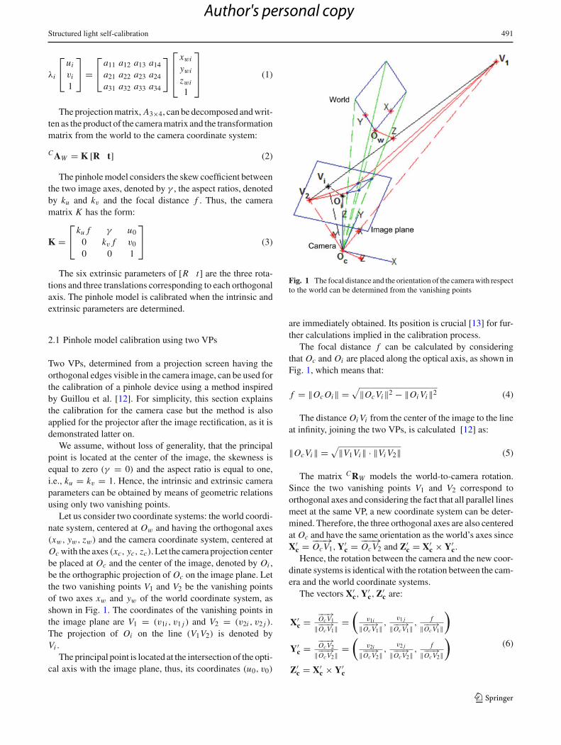
Let us consider two coordinate systems: the world coordi-nate system, centered at Ow and having the orthogonal axes(xw, yw, zw) and the camera coordinate system, centered atOc with the axes (xc, yc, zc). Let the camera projection centerbe placed at Oc and the center of the image, denoted by Oi ,be the orthographic projection of Oc on the image plane. Letthe two vanishing points V1 and V2 be the vanishing pointsof two axes xw and yw of the world coordinate system, asshown in Fig. 1. The coordinates of the vanishing points inthe image plane are V1 = (v1i , v1 j ) and V2 = (v2i , v2 j ).The projection of Oi on the line (V1V2) is denoted byVi .
The principal point is located at the intersection of the opti-cal axis with the image plane, thus, its coordinates (u0, v0)
Fig. 1 The focal distance and the orientation of the camera with respectto the world can be determined from the vanishing points
are immediately obtained. Its position is crucial [13] for fur-ther calculations implied in the calibration process.
The focal distance f can be calculated by consideringthat Oc and Oi are placed along the optical axis, as shown inFig. 1, which means that:
f = ‖Oc Oi‖ =√
‖OcVi‖2 − ‖Oi Vi‖2 (4)
The distance Oi Vi from the center of the image to the lineat infinity, joining the two VPs, is calculated [12] as:
‖OcVi‖ = √‖V1Vi‖ · ‖Vi V2‖ (5)
The matrix C RW models the world-to-camera rotation.Since the two vanishing points V1 and V2 correspond toorthogonal axes and considering the fact that all parallel linesmeet at the same VP, a new coordinate system can be deter-mined. Therefore, the three orthogonal axes are also centeredat Oc and have the same orientation as the world’s axes sinceX′
c = −−−→OcV1, Y′
c = −−−→OcV2 and Z′
c = X′c × Y′
c.Hence, the rotation between the camera and the new coor-
dinate systems is identical with the rotation between the cam-era and the world coordinate systems.
The vectors X′c, Y′
c, Z′c are:
X′c =
−−−→OcV1
‖−−−→OcV1‖
=(
v1i
‖−−−→OcV1‖
,v1 j
‖−−−→OcV1‖
,f
‖−−−→OcV1‖
)
Y′c =
−−−→OcV2
‖−−−→OcV2‖
=(
v2i
‖−−−→OcV2‖
,v2 j
‖−−−→OcV2‖
,f
‖−−−→OcV2‖
)
Z′c = X′
c × Y′c
(6)
123
Author's personal copy

492 R. Orghidan et al.
Fig. 2 Projection of a scene segment through a pinhole camera model
Obtaining the rotation matrix C RW as:
C RW =
⎡⎢⎢⎢⎢⎣
v1i√v2
1i +v21 j + f
v2i√v2
2i +v22 j + f
z′cx
v1 j√v2
1i +v21 j + f
v2 j√v2
2i +v22 j + f
z′cy
f√v2
1i +v21 j + f
f√v2
2i +v22 j + f
z′cz
⎤⎥⎥⎥⎥⎦
(7)
Finally, the translation vector t must be calculated.A segment with a known size in the scene is used con-
sidering, without loss of generality, that one of its two endsis located in the origin of the world coordinate system. Thesegment is determined by the world points W P1 = [0, 0, 0]T
and W P2 = [x p2, yp2, z p2]T , expressed in metric units, asshown in Fig. 2.
The segment can be aligned with its image in the systemof coordinates of the camera using the rotation matrix C RW :
[C P1m
C P2m] = C RW
[W P1
W P2]
(8)
The original segment is imaged by the camera through aprojective transformation and two image points I P1px andI P2px , represented in pixels, are obtained. In the pinholemodel, the metric coordinates of any point in the image canbe calculated by undoing the pixel transformation, the thirdcoordinate being the focal distance:
C Iim = I Pi px − [u0 v0]T (9)
We can now translate the segment on the image plane bysetting its first point on its image I P1m and calculating theposition of the second point. Thus, the translated segment isrepresented by the points I P′
1m and I P′2m :
I P′1m = C I1m
I P′2m = C I1m + ( C P2m − C P1m)
(10)
The obtained segment is parallel to the original one thusforming two similar triangles �OC P1 P2 and �OC P ′
1 Q, asshown in Fig. 2.
Taking advantage of the properties of similar triangles, wecan write:
‖Oc P1‖‖Oc P ′
1‖= ‖P1 P2‖
‖P ′1 Q‖ (11)
Therefore, the distance D from the camera center to theworld center can be calculated as:
D = ‖Oc P1‖ = ‖Oc P ′1‖ · ‖P1 P2‖‖P ′
1 Q‖ (12)
Hence, the translation vector is:
t = DOc P ′
1
‖Oc P ′1‖
(13)
Our method automatically determines the rotation aboutthe X and Y axes of the calibration plane such that the VPsof the world’s XY axes are aligned with the camera I Jaxes. Then, the intrinsic and extrinsic camera parameters canbe obtained by means of the geometric relations presentedabove. The VPs are invariant to translation, therefore, thecamera translation is refined through a Levenberg–Marquardterror minimization algorithm with the initial solution givenby Eq. (13).
2.2 Projected image rectification
The projector is calibrated by projecting the image of acheckerboard onto the same white plane used for the cam-era calibration. Generally, the optical axis of the projectoris not perpendicular to the screen so the pattern is affectedby a double distortion introduced by the keystone effect andby the camera perspective transformation. The pattern is rec-tified by eliminating the two distortions. Figure 3 presentsthe four points Pi that bound the projected pattern. We con-sider a distortion-free projected pattern as a rectangle havingthe same VPs as the screen. Consequently, geometric rela-tions can be used to calculate the positions of the points P ′
ithat bound such a projection. Let Vx and Vy be the coor-dinates of the VPs formed in the camera image along theX and Y world axes, respectively. The keystone effect isremoved by enforcing the co-linearity between the points(P ′
1, P ′2, Vx ) and (P ′
4, P ′3, Vx ) along the X direction and
123
Author's personal copy

Structured light self-calibration 493
Fig. 3 The keystone effect is removed when the VPs of the plane andof the projected image are coincident
Fig. 4 After removing the keystone effect, the VPs of the projectorare identified. a Visible keystone effect affecting the projection. b Theundistorted projection
between the points (P ′1, P ′
4, Vy) and (P ′2, P ′
3, Vy) along theY direction.
If the point P1 = P ′1, then the positions of the other three
points are calculated from the intersections of the followinglines:
P ′2 = (P ′
1, Vx )⋂
(P2, Vy)
P ′4 = (P4, Vx )
⋂(P1, Vy)
P ′3 = (P ′
4, Vx )⋂
(P ′2, Vy).
(14)
The effect of the image rectification is illustrated in Fig. 4.The keystone effect, clearly visible in Fig. 4a, appears whenprojecting a checkerboard with orthogonal edges on a flatsurface. After removing the distortion, the corrected imageis projected and the distortion-free pattern appears as shownin Fig. 4b. Note that the VPs of the projector appear in theprojector image.
Fig. 5 Flowchart of the calibration of a SL system
Let us consider that the camera and the projector refer-ence systems, see Fig. 5a, are placed at {C} and {P}, respec-tively. Both devices are randomly oriented and point towardsa planar surface aligned with the XY plane of the worldcoordinate system {W }. The homography W HC between theworld screen plane and the camera image plane, containingthe points Si = [xsi ysi 1]T and Qi = [ui vi 1]T , respec-tively, can be calculated from the system of Eq. (15) using atleast four points.[
ui
vi
]=
[h11 h12
h21 h22
] [xsi
ysi
](15)
Similarly, the homography C HP between the projectorand the camera image is determined. Thus, estimating thehomography between the screen and the projector becomesstraight forward, as shown in relation (16):
W HP =W HC ·C HP (16)
Figure 5b shows the camera image containing the cameracalibration plane, defined by the points Qi and the projectedpattern, bounded by the points Pi . The projector’s keystoneeffect is removed, independently of the camera’s parameters,by applying a transformation to the original pattern, shown inFig. 5c. After the transformation, the resulting projection hasthe same VPs as the target screen. Considering the constraints
123
Author's personal copy
494 R. Orghidan et al.
imposed by the screen’s VPs, the points P ′i are calculated
on the camera image, see Fig. 5d. Using the homographyP HC = inv(C HP ), the new points P ′
i on the projector aredetermined. Figure 5e shows the projector image containingalso the estimated position of the points Qi and Pi . Thus, thepattern can be rectified by a homography derived for a givenprojector–screen configuration.
However, applying the homography directly will produceoversampled or subsampled images. New patterns can bedesigned when structured patterns, as the checkerboard, areprojected. Using the homography W HP to relate the edges ofa rectified projection on the screen with the projector image,a new pattern can be generated as shown in the Fig. 5d, e.Besides, in the case of a non-structured pattern, high-qualityimages can be obtained by adding an interpolation methodto the transformation.
The distortion of the projector’s view, shown in Fig. 5e,strongly binds with the projector–camera–screen configura-tion. Thus, the VPs of the projector’s distorted image can beused for calibrating the pinhole model of the projector.
Briefly, the calibration algorithm has the following steps:
1. Determine the VPs of the camera using the target screen,2. Generate the rectified pattern,3. Determine the projector’s VPs,4. Calibrate the camera and the projector using their respec-
tive VPs by using the method explained in Sect. 2.1.
3 Structured light for 3D reconstruction
SL techniques are used for overcoming the limitations of pas-sive stereovision due to the lack of correspondences in thecase of scenes with non-textured objects. In this work, weproject a coded pattern built using a spatial neighborhoodcoding technique based on a De Bruijn sequence. We usedthe optimized De Bruijn pattern designed by Pages et al. [22]using 4 hue levels and 64 colored vertical slits separated byblack bands. This technique permits the identification of thecorrespondences in one-shot and is suitable for the recon-struction of both static and moving objects. A De Bruijnsequence of order m in conjunction with n different symbolsforms a single dimensional structure of length n·m containingunique instances of substrings of length m. The backgroundis removed by using a threshold for the low values of theluminance.
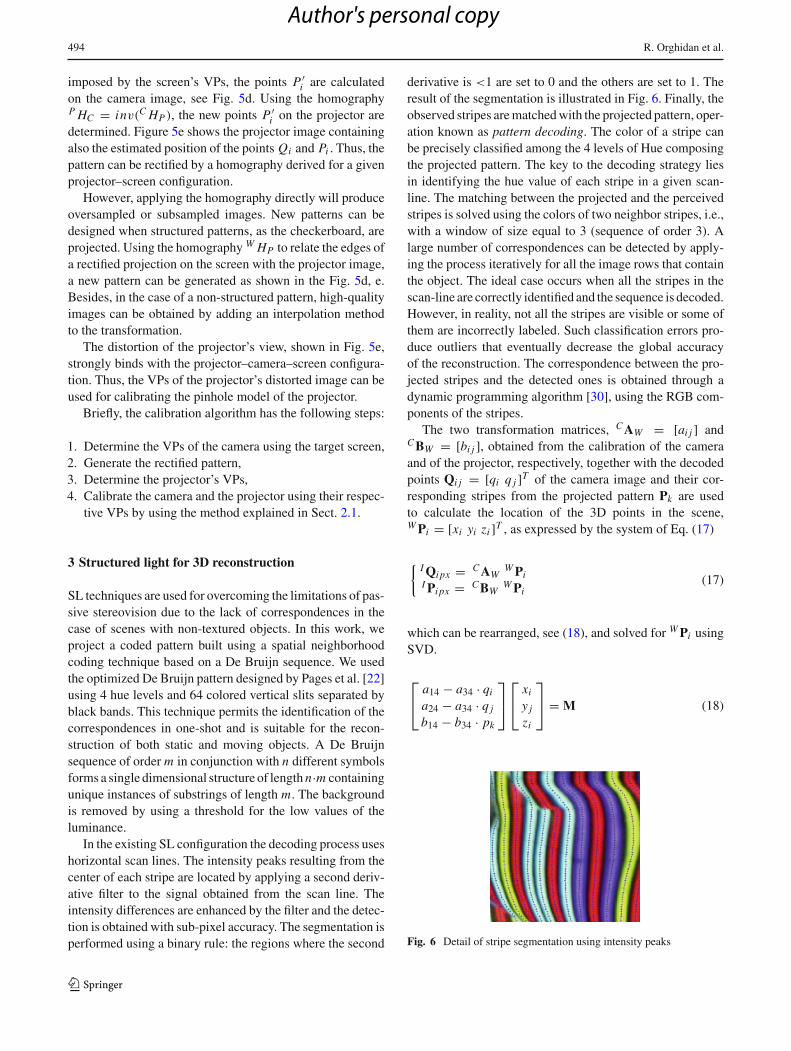
In the existing SL configuration the decoding process useshorizontal scan lines. The intensity peaks resulting from thecenter of each stripe are located by applying a second deriv-ative filter to the signal obtained from the scan line. Theintensity differences are enhanced by the filter and the detec-tion is obtained with sub-pixel accuracy. The segmentation isperformed using a binary rule: the regions where the second
derivative is <1 are set to 0 and the others are set to 1. Theresult of the segmentation is illustrated in Fig. 6. Finally, theobserved stripes are matched with the projected pattern, oper-ation known as pattern decoding. The color of a stripe canbe precisely classified among the 4 levels of Hue composingthe projected pattern. The key to the decoding strategy liesin identifying the hue value of each stripe in a given scan-line. The matching between the projected and the perceivedstripes is solved using the colors of two neighbor stripes, i.e.,with a window of size equal to 3 (sequence of order 3). Alarge number of correspondences can be detected by apply-ing the process iteratively for all the image rows that containthe object. The ideal case occurs when all the stripes in thescan-line are correctly identified and the sequence is decoded.However, in reality, not all the stripes are visible or some ofthem are incorrectly labeled. Such classification errors pro-duce outliers that eventually decrease the global accuracyof the reconstruction. The correspondence between the pro-jected stripes and the detected ones is obtained through adynamic programming algorithm [30], using the RGB com-ponents of the stripes.
The two transformation matrices, C AW = [ai j ] andC BW = [bi j ], obtained from the calibration of the cameraand of the projector, respectively, together with the decodedpoints Qi j = [qi q j ]T of the camera image and their cor-responding stripes from the projected pattern Pk are usedto calculate the location of the 3D points in the scene,W Pi = [xi yi zi ]T , as expressed by the system of Eq. (17)
{ I Qi px = C AWW Pi
I Pi px = C BWW Pi
(17)
which can be rearranged, see (18), and solved for W Pi usingSVD.
⎡⎣
a14 − a34 · qi
a24 − a34 · q j
b14 − b34 · pk
⎤⎦
⎡⎣
xi
y j
zi
⎤⎦ = M (18)
Fig. 6 Detail of stripe segmentation using intensity peaks
123
Author's personal copy

Structured light self-calibration 495
where,
M =⎡⎣
a31 · qi − a11 a32 · qi − a12 a33 · qi − a13
a31 · q j − a21 a32 · q j − a22 a33 · q j − a23
a31 · pk − a11 a32 · pk − a12 a33 · pk − a13
⎤⎦ (19)
4 Experimental results
The robustness to noise of the proposed calibration methodwas explored through a set of experiments using syntheticdata. Working in a synthetic environment has the advantagethat ground truth values are available and the deviation ofthe calculated parameters can be accurately determined. The
Fig. 7 Experimental synthetic setup for calibration
synthetic setup used for our experiments contains a camera,a projector and a planar surface used as projection screen,as shown in Fig. 7. The world points were projected using alinear pinhole model. The camera image and the projector’srectified pattern are pictured in Fig. 8 that also contains thescreen edges as a reference.
In real situations, the noise is present mostly at the imagelevel, hence, we added different levels of Gaussian noise onthe 2D pixel coordinates of the synthetic images. The VPscorresponding to two orthogonal directions were extractedfor each noise level, as shown in Fig. 9. Based on the posi-tion of the VPs the camera parameters were estimated. Fiftyiterations have been applied at each noise level and the aver-age values were considered for each parameter. The repro-jection errors and the corresponding standard deviation forthe calibrated camera and projector were calculated for dif-ferent noise levels and their values, expressed in pixels, arepresented in the leftmost image of Fig. 10. The righthandside of the same figure contains the 3D reconstruction error,expressed as a percentage of the size of a reference cube. Thecamera focal distance and its translation with respect to theworld reference system were compared with the referenceones, as shown in Fig. 11. Since both the camera and the pro-jector are calibrated independently using the same method,the relation noise-error is similar in both calibrations.
Further tests of the proposed calibration have been con-ducted by comparing its performance with an existing cal-ibration toolbox (Figs.12, 13, 14), namely, the ProCam [8]implemented by Hurtos et al. [16] and later on improved byFernandez [9]. The toolbox uses the well-known Bouguet’scamera calibration toolbox [3] which implements Zhang’scalibration [32].
Bouguets calibration method uses a planar checkerboardgrid successively placed in front of the camera at several loca-tions. Once the camera is calibrated using the corners of theprinted checkerboard pattern, the position of the plane withrespect to the camera can be recovered and the 3D locations
Fig. 8 Synthetic camera andprojector images
123
Author's personal copy

496 R. Orghidan et al.
Fig. 9 The VPs are deviated bythe noise that affects the imagepoints
Fig. 10 2D reprojection error and depth estimation error using camera and projector calibration affected by different noise levels
Fig. 11 Translation and focaldistance variation for the cameracalibration affected by differentnoise levels
of the projected pattern’s features can be calculated. Thus,the projector can be calibrated. The comparison tests wereperformed using a linear pinhole model, i.e., by setting thedistortion parameters to zero in the Bouguet’s method. Thepixel reprojection error obtained using the ProCam toolbox
were in the range of μcam ∈ [1.3697, 2.7041] pixels for thecamera and μproj ∈ [3.2556, 3.7661] pixels for the projector.The same calibration planes were used and the reprojectionerror was calculated using our method obtaining an errorin the range μcam ∈ [1.2085, 2.5498] pixels for the cam-
123
Author's personal copy

Structured light self-calibration 497
Fig. 12 Several positions of thecalibration plane with theprojected pattern
Table 1 2D reprojection error in an experiment with real data for 10calibration planes using the proposed method
Camera Projector
Pos. Err. (px.) Pos. Err. (px.) Pos. Err. (px.) Pos. Err. (px.)
1 2.0259 2 1.4648 1 1.1640 2 1.0825
3 2.5498 4 2.0387 3 0.4111 4 3.3566
5 1.4428 6 1.9825 5 0.1553 6 2.7940
7 1.2085 8 1.9976 7 1.4465 8 0.1090
9 2.5127 10 1.2706 9 0.2120 10 1.3327
Fig. 13 VPs detection using a printed pattern placed on the calibrationscreen
Fig. 14 The VPs of the camera and of the rectified projector image areidentical
Fig. 15 SL setup placed in an ad hoc configuration in front of an officedoor
era and μproj ∈ [0.1090, 3.3566] pixels for the projector, aspresented in Table 1 for each plane.
The presented calibration was evaluated by performingone-shot reconstructions of objects placed in front of the SLsystem. The correspondence problem is solved using a color-encoded light pattern. The multi-slit pattern is a De Bruijnsequence built using 4 colors and 64 stripes, as detailed inSect. 3.
The experimental setup was composed by a Canon EOS500D camera, a Hitachi CP-X260 LCD projector and a lap-top with an Intel Pentium Dual CPU at 2.16 GHz with 2 GBRAM. The components were placed in an ad hoc configura-tion, as shown in Fig. 15.
The accuracy of the reconstruction was estimated using aplanar surface. The distance from the 3D points and an idealplane, fitted to the cloud of points, was calculated and was
123
Author's personal copy
498 R. Orghidan et al.
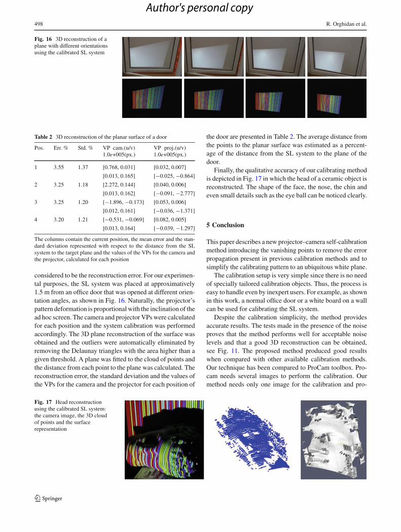
Fig. 16 3D reconstruction of aplane with different orientationsusing the calibrated SL system
Table 2 3D reconstruction of the planar surface of a door
Pos. Err. % Std. % VP cam.(u/v)1.0e+005(px.)
VP proj.(u/v)1.0e+005(px.)
1 3.55 1.37 [0.768, 0.031] [0.032, 0.007]
[0.013, 0.165] [−0.025, −0.864]
2 3.25 1.18 [2.272, 0.144] [0.040, 0.006]
[0.013, 0.162] [−0.091, −2.777]
3 3.25 1.20 [−1.896, −0.173] [0.053, 0.006]
[0.012, 0.161] [−0.036, −1.371]
4 3.20 1.21 [−0.531, −0.069] [0.082, 0.005]
[0.013, 0.164] [−0.039, −1.297]
The columns contain the current position, the mean error and the stan-dard deviation represented with respect to the distance from the SLsystem to the target plane and the values of the VPs for the camera andthe projector, calculated for each position
considered to be the reconstruction error. For our experimen-tal purposes, the SL system was placed at approximatively1.5 m from an office door that was opened at different orien-tation angles, as shown in Fig. 16. Naturally, the projector’spattern deformation is proportional with the inclination of thead hoc screen. The camera and projector VPs were calculatedfor each position and the system calibration was performedaccordingly. The 3D plane reconstruction of the surface wasobtained and the outliers were automatically eliminated byremoving the Delaunay triangles with the area higher than agiven threshold. A plane was fitted to the cloud of points andthe distance from each point to the plane was calculated. Thereconstruction error, the standard deviation and the values ofthe VPs for the camera and the projector for each position of
the door are presented in Table 2. The average distance fromthe points to the planar surface was estimated as a percent-age of the distance from the SL system to the plane of thedoor.
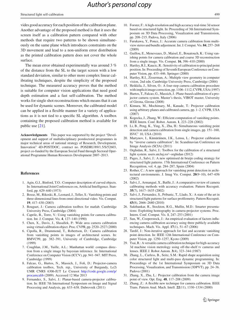
Finally, the qualitative accuracy of our calibrating methodis depicted in Fig. 17 in which the head of a ceramic object isreconstructed. The shape of the face, the nose, the chin andeven small details such as the eye ball can be noticed clearly.
5 Conclusion
This paper describes a new projector–camera self-calibrationmethod introducing the vanishing points to remove the errorpropagation present in previous calibration methods and tosimplify the calibrating pattern to an ubiquitous white plane.
The calibration setup is very simple since there is no needof specially tailored calibration objects. Thus, the process iseasy to handle even by inexpert users. For example, as shownin this work, a normal office door or a white board on a wallcan be used for calibrating the SL system.
Despite the calibration simplicity, the method providesaccurate results. The tests made in the presence of the noiseproves that the method performs well for acceptable noiselevels and that a good 3D reconstruction can be obtained,see Fig. 11. The proposed method produced good resultswhen compared with other available calibration methods.Our technique has been compared to ProCam toolbox. Pro-cam needs several images to perform the calibration. Ourmethod needs only one image for the calibration and pro-
Fig. 17 Head reconstructionusing the calibrated SL system:the camera image, the 3D cloudof points and the surfacerepresentation
123
Author's personal copy
Structured light self-calibration 499
vides good accuracy for each position of the calibration plane.Another advantage of the proposed method is that it uses thescreen itself as a calibration pattern compared with othermethods that require two patterns to be shown simultane-ously on the same plane which introduces constraints on the3D movement and lead to a non-uniform error distributionas the printed calibration pattern does not cover the wholesurface.
The mean error obtained experimentally was around 3 %of the distance from the SL to the target screen with a lowstandard deviation, similar to other more complex linear cal-ibrating techniques, despite the simplicity of the proposedtechnique. The measured accuracy proves that the methodis suitable for computer vision applications that need gooddepth estimation and a fast self-calibration. The methodworks for single shot reconstructions which means that it canbe used for dynamic scenes. Moreover, the calibrated modelcan be applied in a flexible manner for a variety of applica-tions as it is not tied to a specific SL algorithm. A toolboxcontaining the proposed calibration method is available forpublic use [21].
Acknowledgments This paper was supported by the project “Devel-opment and support of multidisciplinary postdoctoral programmes inmajor technical areas of national strategy of Research, Development,Innovation” 4D-POSTDOC, contract no. POSDRU/89/1.5/S/52603,project co-funded by the European Social Fund through Sectoral Oper-ational Programme Human Resources Development 2007–2013.
References
1. Agin, G.J., Binford, T.O.: Computer description of curved objects.In: International Joint Conferences on, Artificial Intelligence. Stan-ford, pp. 629–640 (1973)
2. Bosse, M., Rikoski, R., Leonard, J., Teller, S.: Vanishing points andthree-dimensional lines from omni-directional video. Vis. Comput.19, 417–430 (2003)
3. Bouguet, J.: Camera calibration toolbox for matlab. CambridgeUniversity Press, Cambridge (2004)
4. Caprile, B., Torre, V.: Using vanishing points for camera calibra-tion. Int. J. Comput. Vis. 4, 127–140 (1990)
5. Chen, X., Davis, J., Slusallek, P.: Wide area camera calibrationusing virtual calibration object. Proc. CVPR, pp. 2520–2527 (2000)
6. Cipolla, R., Drummond, T., Robertson, D.: Camera calibrationfrom vanishing points in images of architectural scenes. In:BMVC99, pp. 382–391, University of Cambridge, Cambridge(1999)
7. Coughlan, J.M., Yuille, A.L.: Manhattan world: compass direc-tion from a single image by bayesian inference. In: InternationalConference on Computer Vision (ICCV), pp. 941–947. MIT Press,Cambridge (1999)
8. Falcao, G., Hurtos, N., Massich, J., Fofi, D.: Projector-cameracalibration toolbox, Tech. rep., University of Burgundy, Le2iUMR CNRS 6306-IUT Le Creusot http://code.google.com/p/procamcalib (2009). Accessed 12 Mar 2013
9. Fernandez, S., Salvi, J.: Planar-based camera-projector calibra-tion. In: IEEE 7th International Symposium on Image and SignalProcessing and Analysis, pp. 633–638. Dubrovnik (2011)
10. Forster, F.: A high-resolution and high accuracy real-time 3d sensorbased on structured light. In: Proceeding of 3th International Sym-posium on 3D Data Processing, Visualization and Transmission,pp. 208–215. Padova, Italy (2006)
11. Furukawa, Y., Ponce, J.: Accurate camera calibration from multi-view stereo and bundle adjustment. Int. J. Comput. Vis. 84, 257–268(2009)
12. Guillou, E., Meneveaux, D., Maisel, E., Bouatouch, K.: Using van-ishing points for camera calibration and coarse 3D reconstructionfrom a single image. Vis. Comput. 16, 396–410 (2000)
13. Hartley, R.I., Kaucic, R.: Sensitivity of calibration to principal pointposition. In: Proceeding of Seventh European Conference on Com-puter Vision, pp. 433–446. Springer (2000)
14. Hartley, R.I., Zisserman, A.: Multiple view geometry in computervision, 2nd edn. Cambridge University Press, Cambridge (2004)
15. Heikkila, J., Silven, O.: A four-step camera calibration procedurewith implicit image correction, pp. 1106–1112, CVPR, USA (1997)
16. Hurtos, T., Falcao, G., Massich, J.: Plane-based calibration of a pro-jector camera system. Master’s thesis, VIBOT master, Universityof Girona, Girona (2008)
17. Kimura, M., Mochimary, M., Kanade, T.: Projector calibrationusing arbitrary planes and calibrated camera, pp. 1–2. CVPR, USA(2007)
18. Kogecka, J., Zhang, W.: Efficient computation of vanishing points.IEEE Intern. Conf. Robot. Autom. 1, 223–228 (2002)
19. Li, B., Peng, K., Ying, X., Zha, H.: Simultaneous vanishing pointdetection and camera calibration from single images, pp. 151–160,ISVC’ 10, USA (2010)
20. Martynov, I., Kämäräinen, J.K., Lensu, L.: Projector calibrationby “inverse camera calibration”. In: Scandinavian Conference onImage Analysis (SCIA) (2011)
21. Orghidan, R., Salvi, J.: Toolbox for the calibration of a structuredlight system. users.utcluj.ro/∼orghidan (2012)
22. Pages, J., Salvi, J.: A new optimised de bruijn coding strategy forstructured light patterns. 17th International Conference on PatternRecognition, vol. 4, pp. 284–287, Spain (2004)
23. Rother, C.: A new approach for vanishing point detection in archi-tectural environments. J. Imag Vis. Comput. 20(9–10), 647–656(2002)
24. Salvi, J., Armangué, X., Batlle, J.: A comparative review of cameracalibrating methods with accuracy evaluation. Pattern Recognit.35(7), 1617–1635 (2002)
25. Salvi, J., Fernandez, S., Pribanic, T., Llado, X.: A state of the art instructured light patterns for surface profilometry. Pattern Recognit.43(8), 2666–2680 (2010)
26. Sukthankar, R., Stockton, R.G., Mullin, M.D.: Smarter presenta-tions: Exploiting homography in camera-projector systems. Proc.Intern. Conf. Comput. Vis. 1, 247–253 (2001)
27. Sun, W., Cooperstock, J.: An empirical evaluation of factors influ-encing camera calibration accuracy using three publicly availabletechniques. Mach. Vis. Appl. 17(1), 51–67 (2006)
28. Tardif, J.: Non-iterative approach for fast and accurate vanishingpoint detection. In: IEEE 12th International Conference on Com-puter Vision, pp. 1250–1257, Kyoto (2009)
29. Tsai, R.: A versatile camera calibration technique for high-accuracy3d machine vision metrology using off-the-shelf tv cameras andlenses. IEEE J. Robot Autom. 3(4), 323–344 (1987)
30. Zhang, L., Curless, B., Seitz, S.M.: Rapid shape acquisition usingcolor structured light and multi-pass dynamic programming. In:Proceedings of the 1st International Symposium on 3D DataProcessing, Visualization, and Transmission (3DPVT), pp. 24–36.Padova (2001)
31. Zhang, X., Zhu, L.: Projector calibration from the camera imagepoint of view. Opt. Eng. 48, 117–208 (2009)
32. Zhang, Z.: A flexible new technique for camera calibration. IEEETrans. Pattern Anal. Mach. Intell. 22(11), 1330–1334 (2000)
123
Author's personal copy

500 R. Orghidan et al.
Author Biographies
Radu Orghidan received hisPh.D. degree in InformationTechnologies in 2006 from theUniversity of Girona, Spain, andthe B.Sc. degree in Automa-tion and Informatics Engineer-ing in 2001 from the Techni-cal University of Cluj-Napoca(TUCN), Romania. Currently, heis a postdoctoral researcher inthe computer vision field at theTUCN. His research is focusedon 3D perception using stereo-scopic techniques, 3D interactivetools, image processing, multi-media technologies and eLearn-ing.
Joaquim Salvi graduated inComputer Science at the Tech-nical University of Catalonia in1993, received the DEA (M.Sc.)in Computer Science in July1996 and the Ph.D. in IndustrialEngineering in 1998 both at theUniversity of Girona, Spain. Heis Professor of Computer Visionat the Computer Architecture andTechnology Department and atthe Computer Vision and Robot-ics Group, University of Girona;he was a visiting professor at theOcean Systems Lab, Heriot-Watt
University (UK). His current interests are in the field of computer visionand mobile robotics, focused on visual SLAM, structured light, stere-ovision, and camera calibration. Currently, he is the director of thePolytechnic School of the University of Girona.
Mihaela Gordan received thePh.D. degree in Electronics andTelecommunications Engineer-ing and the M.Sc. degree inApplied Electronics Engineeringin 2004 and 1996, respectively,from the Technical Universityof Cluj-Napoca, Romania. Cur-rently, she is an Associate Pro-fessor at the same university inthe Department of Communi-cation, Faculty of Electronics,Telecommunications and Infor-mation Technology. She is anexpert in digital image process-
ing and analysis, multimodal image analysis, fuzzy logic, fuzzy imageprocessing and machine learning for image analysis and understanding.
Camelia Florea received theB.Sc. and Ph.D. degrees inElectronics and Telecommuni-cations Engineering in 2005and 2009, respectively, from theTechnical University of Cluj-Napoca, Romania. Currently, sheis an Assistant Professor at thesame university in the Depart-ment of Communication, Fac-ulty of Electronics, Telecommu-nications and Information Tech-nology. Her research interestsare: signal processing and analy-sis, images and video sequences
compression, compressed domain data processing, multimedia tech-nologies, artificial intelligence and fuzzy logic.
Joan Batlle Ms.C. in Physicsby the Universitat Autonomade Barcelona, Ph.D. in Com-puter Engineering by the Univer-sitat Politècnica de Catalunya-Barcelona. Professor of Com-puter Science at the Universityof Girona, teaching matters con-cerning Computer Vision Sys-tems, and advanced Technolo-gies. He was Rector of the Uni-versity of Girona from 2002 to2005.
123
Author's personal copy