Embed Size (px)
Citation preview
2
-
ORISSA POWER TRANSMISSION CORPORATION LIMITED
REGD. OFFICE, JANAPATH, BHUBANESWAR –751022
ORISSA. TENDER FOR DIVERSION OF EHT LINES FOR PROPOSED HARIDASPUR-PARADEEP RAILWAY LINE
Tender Notice No-51/2009-10 Tender Specification Nos- Sr. G.M (CPC)- EHT Line Diversion-Haridaspur-99/2009-10
DATE OF OPENING - 29.12.2009 COST OF TENDER PAPER-Rs.10,000.00+4% VAT
3
ORISSA POWER TRANSMISSION CORPORATION LIMITED
REGD. OFFICE, JANAPATH, BHUBANESWAR –751022 ORISSA.
TENDER NOTICE NO -51/2009-10 For and on behalf of ORISSA POWER TRANSMISSION CORPORATION
Limited, Sr. G.M. (C.P.C.) invites Tenders from reputed Electrical Contractors having
adequate experience as prescribed in the tender specification and valid HT/EHT
license from competent licensing authority for Diversion of 132 KV and 220 KV EHT
Lines in OPTCL System for the proposed Haridaspur-Paradeep Railway line work ,in
turn key basis and in two packages. Tender papers shall be sold from 27.11.2009 to
28.12.2009. Interested firms may visit OPTCL’s official website
http://www.OPTCL.co.in for detail specifications . The FIRMS are requested to visit
the proposed work locations prior to the bidding, for better understanding of the work.
SR. GENERAL MANAGER [C.P.C.]
4
NOTICE INVITING TENDER ORISSA POWER TRANSMISSION CORPORATION LIMITED,
REGD. OFFICE: JANPATH, BHUBANESWAR – 751 022, ORISSA, ORISSA.
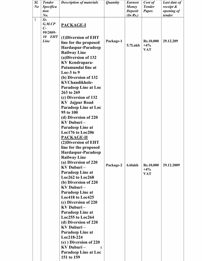
TENDER NOTICE NO. 51/2009-10 For and on behalf of the ORISSA POWER TRANSMISSION CORPORATION Limited, the undersigned invites bids under two-part bidding system in double-sealed cover for the works as mentioned below, duly superscribed with tender specification number and date of opening, from experienced HT/EHT electrical contractors having adequate experience in construction of 132 KV and 220 KV transmission lines for diversion of EHT lines for proposed Haridaspur-Paradeep Railway line work.
5
Sl. No
Tender Specification No.
Description of materials Quantity
Earnest Money Deposit (In Rs.)
Cost of Tender Paper.
Last date of receipt & opening of tender
1
Sr. G.M.CPC-99/2009-10 EHT Line
PACKAGE-I
(1)Diversion of EHT line for the proposed Hardaspur-Paradeep Railway Line (a)Diversion of 132 KV Kendrapara- Patamundai line at Loc-3 to 9 (b) Diversion of 132 KVChandikhole- Paradeep Line at Loc 263 to 269 (c) Diversion of 132 KV Jajpur Road Paradeep Line at Loc 95 to 100 (d) Diversion of 220 KV Duburi –Paradeep Line at Loc176 to Loc206 PACKAGE-II (2)Diversion of EHT line for the proposed Hardaspur-Paradeep Railway Line (a) Diversion of 220 KV Duburi –Paradeep Line at Loc262 to Loc268 (b) Diversion of 220 KV Duburi –Paradeep Line at Loc418 to Loc425 (c) Diversion of 220 KV Duburi –Paradeep Line at Loc255 to Loc264 (d) Diversion of 220 KV Duburi –Paradeep Line at Loc218-224 (e) ) Diversion of 220 KV Duburi –Paradeep Line at Loc 151 to 159
Package-1 Package-2
5.7Lakh 6.6lakh
Rs.10,000 +4% VAT Rs.10,000 +4% VAT
29.12.209 29.12.2009
6
The tender specification documents can be had from the office of the undersigned on payment of non-refundable cost of tender specification documents in the shape of cash from 10 A .M. to 3 P.M. during 27.11.2009 to 28.12.2009 (both days inclusive) on any working day either in person or by remitting demand draft payable to Drawing & Disbursing Officer, ORISSA POWER TRANSMISSION CORPORATION Limited, Regd. Office: Janpath, Bhubaneswar- 751 022. No other mode of payment is acceptable. No tender documents will be sold on any other day except as indicated.
The specification can also be down loaded from OPTCL’s official web site and the same may be submitted alongwith the cost of tender document by way of demand draft/ pay order payable to D.D.O ,OPTCL Ltd. Janpath, Bhubaneswar at the time of submission of tender document. Incase any deviation is found in the tender document submitted by the Tenderers from the content mentioned in our web site and/ or non submission of cost of tender documents, the tender shall liable to be rejected at any stage of the contract. The Tenderers has to indemnify OPTCL for any loss accruing due to such alternation in the terms and conditions of the tender document & / or for such alternation, resulting in the cancellation of the contract. The intending bidders, who want to get a copy of the tender specification document by post, are required to deposit an additional amount of Rs.1000/- over and above the cost of the tender specification, mentioned under heading “Cost of tender specification”. Complete bid for the works will be received upto 1 P.M of 29.12.2009. only and the same will be opened at 3 P.M. on the on the same day. Date and time of opening of price bids in respect of two-part tenders shall be intimated to the techno-commercially responsive bidders only. In the event of any specified date for the sale, submission or opening of bids being declared a holiday for purchaser, the bids will be sold/ received/ opened upto the appointed times on the next working day. Only one representative of the bidder will be allowed to participate in the bid opening. OPTCL also reserves the right to accept or reject the tender without assigning any reasons thereof, if the situation so warrants. OPTCL shall not be responsible for any postal delay at any stage. QUALIFYING CRITERION FOR AWARD OF OPTCLTURNKEY 132 KV AND 220 KV LINE DIVERSION WORK
(A) GENERAL QUALIFYING CRITERION
(1) There is no Limitation for awarding OPTCL turnkey projects for deposit work tenders
(2)The performance B.G. to be submitted by the Firms shall be capable of
being encashed at any branch of the issuing bank at Bhubaneswar of encashment at the operating branch of the Bank at Bhubaneswar.
(3) In case bidders intend to bid for the project in joint venture with another firm, the parties together must be able to meet the required qualifying
7
criteria. Maximum two nos of Partners are allowed as Joint venture partners and the detailed terms and conditions in this regard are contained in the bid documents.
(B)MINIMUM TECHNICAL QUALIFYING CRITERION
MINIMUM QUALIFYING CRITERION FOR CONSTRUCTION OF 132 KV/220 KV LINES (a) The bidder should be HT/EHT electrical contractor having a valid license from
the competent licensing authority on the date of opening of the tender. (b) The contractor should have executed minimum 5 Km of 220 KV or 10 Km of
132 KV Transmission line in Turn Key Basis earlier& completed successfully . Or, Must have erected, tested and commissioned 20 Km of 110 KV or above
Capacity Transmission line earlier and completed successfully. Or The contractor must have completed 5Km of 400 KV Transmission line earlier
& completed successfully . (C ) The contractor has to get project license from ELBO within one month of
issue of LOI, at his own cost. ©MINIMUM FINANCIAL QUALIFYING CRITERION
TURN OVER-The Contractor should have an average annual turnover of at least 75% of the estimated cost of the project in the last three financial years as per the audited accounts. Incase the contractor bids for more than one project, the average annual turnover shall be at least 75% of the aggregate estimated cost of the projects.
(D) SPECIAL TERMS AND CONDITIONS OF THE BID
(i) Mobilization advance of 10 % value of the contract value (Both supply portion and erection portion) shall be paid against equivalent amount of BG from any nationalized bank having Branch at Bhubaneswar. The mobilization advance shall be recovered proportionately from each running bills of the contractor by OPTCL.10% simple interest shall be charged on the mobilisation advance paid to the firms.
(ii) The extra quantities, if any, to be executed by the firm, shall be billed as per the unit price quoted by the firm.
(iii) The unit price quoted by the firm shall be varable as per IEEMA formula other any standard formula given with this specification, provided with this specification. Items for which formulae are not available , the firms are to quote Firm prices for the same.
(iv) Where valid type test certificate of materials during last five years are available OPTCL shall not insist for further type test.
8
(v) The firms shall solve all ROW at their own cost, shall pay compensation for tree cutting, crop compensation at his own cost.
(E)PAYMENT TERMS
(a) payment against Supply of equipment and materials shall be effected as follows-
(i) 50 % of cost of the material shall be paid on receipt of the material at site against production of Lorry Receipt.
(ii)10% cost of material shall be paid after verification by the consignee.
(iii)30% cost of the material shall be paid after erection of the material at site
(iv) Balance 10 % cost of material shall be paid after successful commissioning of the Sub-Station or Line and handing over to OPTCL
(b) Payment for Erection and commissioning work
(i)90% cost of erection shall be paid on running bill within 30 days on production of the bill to the engineer in charge and verification there of after completion of erection work of the preceding month.
(ii)Balance 10 % cost of the erection shall be paid only after satisfactory commissioning of the project and handing over to OPTCL
(F) OTHER IMPORTANT TERMS AND CONDITIONS
(i) OPTCL shall invite a pre-bid discussion for which the contractors should contact the Sr. G.M., Central Procurement Cell, Head Qrs. Office, OPTCL, Bhubaneswar.
(ii) Work contract taxes shall be deducted from the firms bill as per the prevailing rates
(iii) The Firm shall not include Entry Tax and Service Taxes in their quoted price, which shall be reimbursed to them as per prevailing rate subject to production of documentary evidence.
(iv) For delay in completion of the project, Penalty shall be recovered from the contractor, at the rate of 0.5% per week of delay subject to maximum of 5% of the total contract price.
(v) Bids of the Firms not complying the minimum qualification criterion, not furnishing bid security, furnishing incomplete data’s /price bid, not agreeing to PV price/Not agreeing to to the bid validity date, not agreeing for the security and performance BG, not agreeing to the payment clause, not agreeing to the completion time, not agreeing to defect liability and not agreeing to governing laws, shall be out rightly rejected.
9
(vi)ENGAGEMENT OF SECURITY- The Contractor shall have to engage his own security at his own cost till final handing over of the entire work to OPTCL
(vii)PRICE VARIATION CLAUSE- PV as per IEEMA formula taking November’ 2009 as the base date shall be allowed as per the IEEMA and other formula mentioned under the head”PV Formula”
(ix) QUANTITY VARIATION- Extra quantities executed if any by the firm shall be billed as per the unit quoted rate of the Firm and there shall be no limitation for the extra quantity to be executed.
(x) WORK OFF LOADED FROM FIRMS
Firms from whom, OPTCL have off loaded works due to non-performance, during last FIVE years, shall not be eligible to participate in any of the OPTCL turnkey tenders.
(xi) The participant Firms shall submit an undertaking along with the price bid to the effect that any items missing/not quoted in the price bid, shall be executed free of cost by them without any financial liability to OPTCL and that the said undertaking shall cover all the evaluation criterion as recommended above The condition of rejection of incomplete price bid appearing under the Outright rejection Criterion shall stand deleted.
(xii) Successful bidders may procure tower structures for both S/S & line, preferably from the OPTCL empanelled Rate contractor holders for Supply of Structures.
PV FORMULA PRICE ADJUSTMENT FOR TRANSMISSION LINE 1. General 1.1 Prices for work and materials covered under the scope of this Specification
shall be furnished by the bidder in the manner specified in the Bid Form & Price Schedules. The bidder shall quote base prices for the Ex-Works price component of the equipment / materials. These price components for certain equipment/ materials, as specified, shall be subject to price adjustment to reflect changes in the cost of labourer and material components as per the provisions given below:
1.2 The Ex-Works Price Components for tower accessories such as aviation
signal, danger plate, phase plate, circuit plates, number plate, anti-climbing device, pipe and counterpoise earthing, earthing for river crossing locations, etc and wind measuring equipment shall remain firm and no price adjustment shall be applicable for the price components of these items.
10
1.3 Other Charges viz. inland transportation, inland insurance type test charges, survey soil investigation & painting of towers etc. Shall be firm and no price variation shall be payable for those components.
2. Ex-works Price Component The formulae for calculating the price adjustment to be applied to the Ex-
works price component of the equipment / material will be as follows: A. Fabricated Tower Parts (including Bolts & Nuts) EC1 = EC0 [0.15 + a x A1/ A0 + b x B1 / B0 + 0.11 x L1 / L0] – EC0
Where, EC1 is the price adjustment amount payable on ex-works prices of fabricated tower parts (including Bolts & Nuts), shipment-wise. ECo= Ex-works price component of fabricated tower parts (including ex-
works price of Bolts & Nuts) shipment-wise. A = Price index of steel / re-rolled steel angles of size 150 mm x 150 mm
x 12 mm conforming to IS:2062:1992, as published by IEEMA. B = Price index for Electrolytic High Grade Zinc, as published by
IEEMA. L = All India Consumer Price Index for Industrial workers, as
published by Labour Bureau, Shimla (Govt. of India). a = Co-efficient of Steel;, Value of which shall be between 0.58 & 0.68. b. = Co-efficient of Zinc, Value of which shall be between 0.06 & 0.16
and the sum of a & b shall be 0.74. B. Line Materials B.1 Earthwire EC EW1= EC EW [0.15 + 0.74 (A1 / A0) + 0.11 (L1 / L0) – EC EW Where,
EC EW1 = Price adjustment amount payable on Ex-works price of Earthwire, shipment-wise.
EC EW = Ex-works price for Earthwire, shipment-wise. A = Published price indices for high tensile steel galvanized
wire, as published by CACMAI / Nationally recognized published index acceptable to Employer.
11
L = All India consumer price index for industrial workers as published by Labour Bureau, Shimla (Govt. of India)
12
B.2 Hardware Fittings:
ECHWl= ECHW [0.15 + 0.43 (A1 / A0) + 0.05 (B1 / B0) + 0.21 (C1 /Co) + 0.16 (L1 /Lo)] – ECHW
ECHWl = Price adjustment amount payable on Ex-works price of
Hardware, shipment-wise. EC HW = Ex-works price for Hardware fittings. A, B&C= Price indices for EC grade aluminum ingots, zinc and mild
steel respectively as published by IEEMA. L= All Indian consumer price index for industrial workers as
published by Labour Bureau, Shimila (Govt. of India). B.3 Conductor and Earthwire Accessories.
(i) Mid Span Compression Joint for Earthwire EC1 = ECO [0.20 + 0.40 (A1 / A0) + 0.05 (B1 / B0) + 0.20 (C1/ C0) +0.15 (L1 / L0) - EC0
(ii) Mid Span Compression Joint for ACSR Conductor, Repair Sleeve
for ACSR Conductor EC1 = ECO [0.20 + 0.65 (A1 / A0) + 0.15 (L1 / L0) – EC0
(iii) Vibration Damper for 7/3.15mm, earthwire, Suspension Clamp for
7/3.15mm earth, Tension Clamp for 7/3.15mm, earthwire & Vibration Damper for ACSR Conductor.
EC1 = ECO [0.20 + 0.07 (B1 / B0) + 0.58 (C1 / C0) + 0.15 (L1/L0)]
–ECO (iv) Flexible Copper Bond shall be on Firm price basis. In the above fomulae, EC1 = Price adjustment amount of respective items. EC0 = Ex-works price for Conductor & Earthwire Accessories. A = Price indices for EC grade aluminum ingots, as published by IEEMA. B = Price indices for Electrolytic High Grade Zinc, as published by IEEMA. C = Price indices for Iron & Steel, as published by IEEM.
13
L = All India Average Consumer Price Index for industrial workers as published by Labour Bureau, Shimla (Govt. of India)
B.4 For Disc/Long Rod Insulator
The price adjustment on the Ex-works price component of Disc/ Long Rod Insulator shall be as follows:
EC1 = ECO x [0.15 + a x (A1 / A0) + b (B1 / B0) + 1x (L1/L0)] –ECO Where, EC1 = Price adjustment amount on ex-works price of Insulator or each shipment. ECO = Ex-works price component of Insulator shipment-wise. A & B are price index of Electrolytic High Grade Zinc Ingots, as published by IEEMA and Index number of Wholesale Price of fuel, power, light & lubricant as per RBI Bulletin (Base 1993-94 = 100), respectively. L = Labour Index as published by Labour Bureau, Shimla (Govt. of India) A = Coefficient of Electrolytic High Grade Zinc Ingots, which shall be 0.05 B = Co-efficient of fuel, power light & lubricant as per RBI Bulletin, which shall be 0.53. 1 = Coefficient of laboure index in the ex-factory price of the equipment/ materials, which shall be 0.27
B5. PRICE VARIATION CLAUSE FOR ACSR CONDUCTORS. Price Variation Formula: For Aluminium Conductors Steel Reinforced (ACSR Conductor) P= Po + (A1-A0) x Wt. Of Aluminium Content + (B1 – B0) X Wt. Of HTGS Steel Content Where, P=Ex-Works Price payable in Rs. Per Km. as adjusted in accordance with the price variation clause. Po-Ex-Works price quoted / confirmed in Rs. Per Km.
14
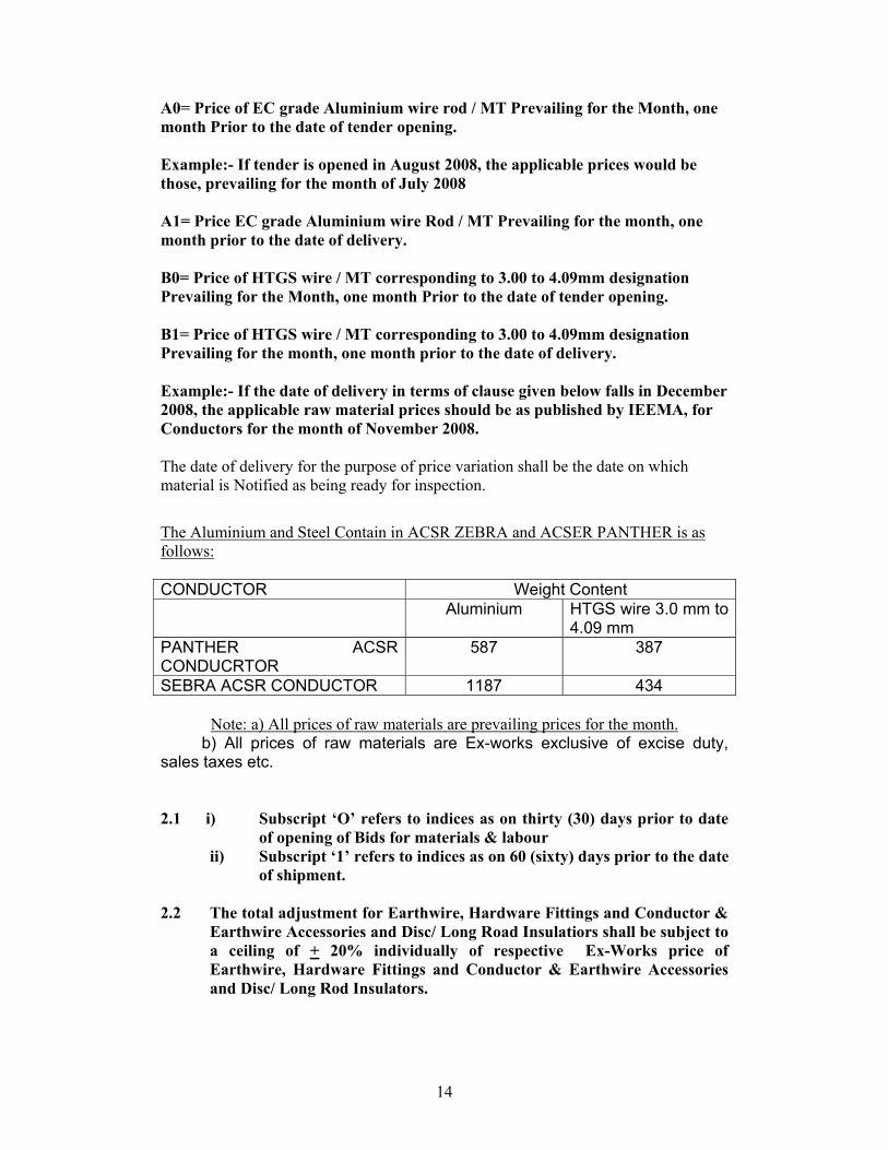
A0= Price of EC grade Aluminium wire rod / MT Prevailing for the Month, one month Prior to the date of tender opening. Example:- If tender is opened in August 2008, the applicable prices would be those, prevailing for the month of July 2008 A1= Price EC grade Aluminium wire Rod / MT Prevailing for the month, one month prior to the date of delivery. B0= Price of HTGS wire / MT corresponding to 3.00 to 4.09mm designation Prevailing for the Month, one month Prior to the date of tender opening. B1= Price of HTGS wire / MT corresponding to 3.00 to 4.09mm designation Prevailing for the month, one month prior to the date of delivery. Example:- If the date of delivery in terms of clause given below falls in December 2008, the applicable raw material prices should be as published by IEEMA, for Conductors for the month of November 2008. The date of delivery for the purpose of price variation shall be the date on which material is Notified as being ready for inspection. The Aluminium and Steel Contain in ACSR ZEBRA and ACSER PANTHER is as follows: CONDUCTOR Weight Content Aluminium HTGS wire 3.0 mm to
4.09 mm PANTHER ACSR CONDUCRTOR
587 387
SEBRA ACSR CONDUCTOR 1187 434
Note: a) All prices of raw materials are prevailing prices for the month. b) All prices of raw materials are Ex-works exclusive of excise duty, sales taxes etc. 2.1 i) Subscript ‘O’ refers to indices as on thirty (30) days prior to date
of opening of Bids for materials & labour ii) Subscript ‘1’ refers to indices as on 60 (sixty) days prior to the date
of shipment. 2.2 The total adjustment for Earthwire, Hardware Fittings and Conductor &
Earthwire Accessories and Disc/ Long Road Insulatiors shall be subject to a ceiling of + 20% individually of respective Ex-Works price of Earthwire, Hardware Fittings and Conductor & Earthwire Accessories and Disc/ Long Rod Insulators.
15
However, the total price adjustment of fabricated tower parts (including Bolts & Nits) shall not be subject to any ceiling whatsoever.
3. Installation (including Civil Works) Price Component The formula for calculation of the monthly price adjustments for
Installation [including civil weeks but excluding survey, soil investigation and aviation signal for river crossing towers (if any) price component shall be as under.
A. Installation price component [including civil works but excluding supply
& placement of reinforcement steel, concreting, survey, soil investigation and aviation signal for river crossing towers (if any)
ER1 = ERo [0.20 + 0.22 (A1/A0) + 0.58 (L1/L0)] –ER0 Where,
ER1 = Price adjustment amount payable on Installation price component (excluding supply & placement of steel and concreting) for each billing.
ER0 = Value of erection work done (excluding supply & placement of
steel and concreting) in billing period as established by Contract.
A = Rate for Diesel Oil as published by Indian Oil Corporation which has jurisdiction over the place of work.
L = Indian field Labour index-namely All India Consumer Price Index for industrial workers as published by Labour Bureau, Shimla (Govt. of India)
B. Supply and Placement of Reinforcement Steel.
ER1 = ERo [0.20 + 0.10 x (A1/A0) + 0.05 x (L1/L0) + 0.65 x (B1/B0] –ER0
Where,
ER1 = Price adjustment amount payable on price components of supply
and Placement of Steel. ER0 = Value of supply & placement of steel in billing period as
established by Contract. A = Rate for Diesel Oil as published by Indian Oil Corporation which
has jurisdiction over the place of work. L = Indian field Labour index-namely All India Consumer Price Index
for industrial workers as published by Labour Bureau, Shimla (Govt. of India)
16
B = Index numbers of wholesale price in India for iron and steel as published by Reserve Bank of India Bulletin ( average of the month).
C. Concreting
ER = ERo [0.20 + 0.20 x (A1/A0) + 0.10 x (L1/L0) + 0.30 x (B1/B0) + 0.20 x (Cl / C0)] –ER0
Where, ER1 = Price adjustment amount payable on price components of
concreting. ER0 = Value of concreting in billing period as established by Contract. A = Rate for Diesel Oil as published by Indian Oil Corporation which
has jurisdiction over the place of work. L = Indian field Labour index-namely All India Consumer Price Index
for industrial workers as published by Labour Bureau, Shimla (Govt. of India)
B = Index numbers of wholesale price in India for Cement as published
by Reserve Bank of India Bulletin (average of the month). C = Index numbers of wholesale price in India for ‘ non-metallic
mineral products (structural clay products)’ as published by Reserve Bank of India Bulletin (average of the month).
3.1 i) Subscript ‘o’ will correspond to thirty (30) days prior to date of
opening of Bids. ii) Subscript ‘1’ will correspond to the month of billing.
3.2 The total price adjustment amount for Installation (including civil works)
price component shall not be subject to any ceiling whatsoever. 4. The bidder shall indicate in his bid the actual values of the coefficients a,
b etc to be adopted, keeping in view the range/ total values given in paras 2 above.
5. The above price adjustment provision shall be invoked by either party
subject t the following further conditions.
a) For the purpose of Price Adjustment on ex-works price components of the equipment, the date of shipmen5t for Goods shall mean scheduled date of shipment or actual date of shipment, whichever is earlier. Scheduled date of shipment will be ex-works date of despatch,
17
governed by the accepted PERT Network / Bar Chart, Similarly, for the purpose of Price Adjustment on Installation price component, the Billing period shall mean the billing period as per Contract time, schedule, i.e,, the agreed Bar Chart or actual period, whichever is earlier. The period for various Installation activities will be as per agreed Installation Bat Chart indicating monthly schedule of I*installation activities for completion of works. However, when the Employer’s specific approval for advancement of shipment/ installation activities has been obtained in such case the said advanced date shall be treated as the schedule date of shipment/ installation activities for the purpose of working out the price adjustment payable. No price increase shall be allowed beyond the original delivery / Installation dates unless specifically stated in the Time Extension Letter, if any, issued by the Employer. The Employer will, however, be entitled to any decrease in the Contract Price which maybe caused due to lower price adjustment amount in case of delivery of Goods/ Installation beyond the original delivery / Installation dates. Therefore, in case of delivery of Goods/ Installation beyond the original delivery/ Installation dates, the liability of the Employer shall be limited to the lower of the price adjustment amount which may work out either on schedule date or actual date of despatch of Goods/ Installation. b) In case IEEA does not publish any of the price indices, as mentioned above, the Bidder shall indicate any nationally recognized published index for respective items and the source of the same shall be furnished in the Bid. c) In case of non-publication of applicable indices on a particular date, which happens to be the applicable date for Price Adjustment purpose, the published indices prevailing immediately prior to the particular date shall be applicable. d) If the price Adjustment amount works out to be positive, the same is payable to the Contractor by the Employer and if it works out to be negative, the same is to be recovered by the Employer from the Contractor. e) The Contractor shall promptly submitted price adjustment
invoices for the supplies made / work done positively within three (3) months from the date of shipment / work done, whether it is positive or negative.
12.3 The Bidder shall also furnish the price breakdown in the appropriate schedules of Bid Form to indicate the following:
i) Ex-works price of the equipment/materials (including tools and tackles etc.)
18
ii) Charges for inland transportation (including port handling) and insurance for delivery of the equipment/materials up to their final destinations.
iii) Lump sum charges towards unloading, storage, insurance, iv) Price break up for spares in line with Clause 18.0 of this Section. v) Sales Tax/ Excise duty/Entry tax and any other levies legally payable
on the transactions between the Owner and the Bidder. vi) Any other charges as per the requirement of Contract/Technical
Specifications. vii) Unit erection, testing and commissioning charges as per the
schedule.
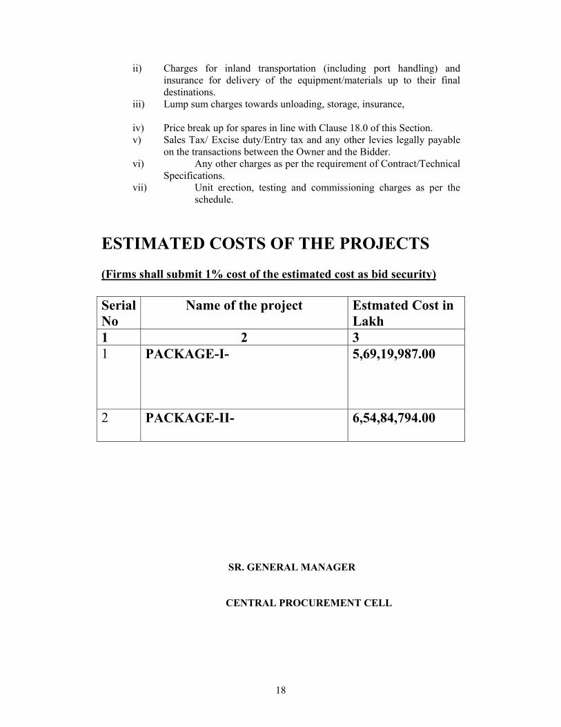
ESTIMATED COSTS OF THE PROJECTS (Firms shall submit 1% cost of the estimated cost as bid security) Serial No
Name of the project Estmated Cost in Lakh
1 2 3 1 PACKAGE-I-
5,69,19,987.00
2 PACKAGE-II-
6,54,84,794.00
SR. GENERAL MANAGER
CENTRAL PROCUREMENT CELL
19
SECTION – INB INSTRUCTION TO BIDDERS
20
INSTRUCTIONS TO BIDDERS CONTENTS
Sl. No. Description Introduction
1.0 General Instructions
2.0 Qualifying Requirements of Bidders
3.0 Cost of Bidding
A. The Bidding Documents 4.0 Contents of Bidding Document
5.0 Understanding of Bid Documents
6.0 Clarifications on Bid Documents
7.0 Amendment to Bidding Documents
B. Preparation of Bids 8.0 Language of Bid
9.0 Local Conditions
10.0 Documents comprising the Bid
11.0 Scope of the Proposal
12.0 Bid Price
13.0 Alternate Proposals
14.0 Price Basis and Payments
15.0 Taxes and Duties
16.0 Price Adjustment
17.0 Time Schedule
18.0 Spare Parts
19.0 Contract Quality Assurance
21
20.0 Insurance
21.0 Maintenance Tools & Tackles
22.0 Erection tools & tackles
23.0 Brand Names
24.0 Bid Guarantee
25.0 Period of Validity of Bids
C. Submission of Bids
26.0 Format of Bid
27.0 Signature of Bids
28.0 Sealing and Marking of Bids
29.0 Deadline for Submission of Bids
30.0 Late Bids
31.0 Modification and withdrawal of Bids
32.0 Information required with the Proposal
D. Bid Opening and Evaluation 33.0 Opening of Bids by Owner
34.0 Clarification of Bids
35.0 Preliminary Examination
36.0 Definitions and Meanings
37.0 Comparison of Bids
38.0 Contacting the Owner
22
F. Award of Contract
39.0 Award Criteria
40.0 Owner’s Right to Accept any Bid and To reject any or all Bids
41.0 Notification of Award
42.0 Signing of Contract
43.0 Contract Performance Guarantee
23
SECTION – INB INSTRUCTION TO BIDDERS
A. INTRODUCTION 1.0 GENERAL INSTRUCTIONS 1.1 The ORISSA POWER TRANSMISSION CORPORATION Limited,
hereinafter called ‘OPTCL’/’OWNER’ will receive bids in respect of equipment to be furnished and erected as set-forth in the accompanying Specifications. All bids shall be prepared and submitted in accordance with these instructions. The tender is invited in two-part basis i.e. (1) Techno-commercial bids consisting all the documents except price bid & (2) Price Bid. Both the bids duly sealed separately shall be kept inside the third sealed cover with superscribed Tender specification No. & Date of Opening.
2.0 QUALIFYING REQUIREMENTS OF BIDDERS
a) As specified in the minimum qualifying Criterion 2 COST OF BIDDING 2.1 The Bidder shall bear all costs and expenses associated with preparation and
submission of its bid including pre and post-bid discussions, technical and other presentations etc., and the Owner will in no case be responsible or liable for those costs, regardless of the conduct or outcome of the bidding process.
B. THE BIDDING DOCUMENTS 3 CONTENTS OF BIDDING DOCUMENT 3.1 The goods and services required, bidding procedures and contract terms are
prescribed in the Bidding Document.
In addition to the Invitation to Bids, the Bidding Document is a compilation of the following sections:
a) Instructions to Bidders – Section INB (Vol.I) b) General Conditions of Contract – Section GCC (Vol.I) c) Erection Conditions of Contract – Section ECC (Vol.I) d) Bid Form and Price Schedules e) Technical Specifications f) Technical Data Sheets
4 UNDERSTANDING OF BID DOCUMENTS
24
4.1 A prospective Bidder is expected to examine all instructions, forms, terms and specifications in the Bid documents and fully inform himself as to all the conditions and matters which may in any way affect the scope of work or the cost thereof. Failure to furnish all information required by the Bid documents or submission of a Bid not substantially responsive to the Bid document in every respect will be at the Bidder’s risk and may result in the rejection of its bid.
5 CLARIFICDATIONS ON BID DOCUMENTS 5.1 If the prospective Bidder finds discrepancies or omissions, in specifications
and document or is in doubt as to the true meaning of any part, he shall at once make a request, in writing, for an interpretation/clarification, to the Owner in triplicate. The Owner, then, will issue interpretation(s) and clarification(s) as he may think fit in writing. After receipt of such interpretation(s) and clarification(s), the Bidder may submit his bid but within the time and date as specified in the Invitation to Bid. All such interpretations and clarifications shall form a part of the Bidding Document and shall accompany the Bidder’s Proposal. A prospective Bidder requiring any clarification on Bidding Document may notify the Owner in writing. The Owner will respond in writing to any request for such clarification of the Bidding Document which it receives not later than fifteen (15) days prior to the deadline for submission of bids prescribed by the Owner. Written copies of the Owner’s response (including an explanation of the query but without identifying its source) will be sent to all prospective Bidders who have received the Bidding Document.
5.2 Verbal clarification and information given by the Owner or his employee(s) or
his representative(s) shall not in any way be binding on the Owner. 6 AMENDMENT TO BIDDING DOCUMENT 6.1 At any time prior to the deadline for submission of bids, the Owner may, for
any reason, whether at its own initiative or in response to a clarification requested by a prospective Bidder, modify the Bidding Document by amendment(s).
6.2 The amendment will be notified in writing or by telex or cable to all
prospective Bidders, which have received the Bidding Document at the address contained in the letter of request for issue of Bidding Document from the Bidders. Owner will bear no responsibility or liability arising out of non-receipt of the same in time or otherwise.
6.3 In order to afford prospective Bidders reasonable time in which to take the
amendment into account in preparing their bids, the Owner may, at its discretion, extend the deadline for the submission of bids.
6.4 Such amendments, clarifications, etc. shall be binding on the Bidders and will
be given due consideration by the Bidders while they submit their bids and invariably enclose such documents as a part of the bid.
25
C. PREPARATION OF BIDS 7 LANGUAGE OF BID 8.1 The bid prepared by the Bidder and all correspondences and documents
relating to the bid, exchanged by the Bidder and the Owner shall be written in the English language, provided that any printed literature furnished by the Bidder may be written in another language so long as accompanied by an English translation of its pertinent passages. Failure to comply with this may disqualify a bid. For purposes of interpretation of the bid, the English translation shall govern.
8 LOCAL CONDITIONS 9.1 It will be imperative on each Bidder to fully inform himself of all local
conditions and factors which may have any effect on the execution of the Contract covered under these documents and specifications. The owner shall not entertain any request for clarifications from the Bidders, regarding such local conditions.
9.2 It must be understood and agreed that such factors have properly been
investigated and considered while submitting the Proposals. No claim for financial adjustment to the Contract awarded under these specifications and documents will be entertained by the Owner. Neither any change in the time schedule of the Contract nor any financial adjustments arising thereof shall be permitted by the Owner, which are based on the lack of such clear information or its effect on the cost of the Works to the Bidder.
9 DOCUMENTS COMPRISING THE BID 10.1 The Bidder shall complete the Bid Form inclusive of Price Schedules,
Technical Data Requirements etc. furnished in the Bidding Documents, indicating for the goods to be supplied and services to be rendered, a brief description of goods and services, quantity and prices.
10.2 The Bidder shall also submit documentary evidence to establish that the
Bidder meets the Qualification Requirements as detailed in Clause 2.0 above including the minimum qualification as stipulated and accompanying Special Conditions of Contract.
10.3 The Bid Guarantee shall be furnished in a separate cover in accordance with
clause 24.0 of Section INB. 10 SCOPE OF THE PROPOSAL 11.1 The scope of the Proposal shall be on the basis of a single Bidder’s
responsibility, completely covering all the work and equipment specified under the accompanying Technical Specifications. It will include the following -
26
a) detailed design of the equipment; b) complete manufacture including shop testing; c) providing Engineering drawing, data, operational manual, etc. for the
Owner’s approval; d) packing and transportation from the manufacturer’s works to the site; e) receipt, storage, preservation and conservation of equipment at the site; f) pre-assembly, if any, erection, testing and commissioning of all the
equipment; g) reliability tests and performance and guarantee tests on completion of
commissioning; and i) erection and commissioning procedure j) erection and commissioning programme. k) Details of steel and cement to be used by the firm.
11.2 Bids containing deviations from provisions relating to the following clauses will be considered as non-responsive:
a) Price Basis and Payments & Price Adjustment: Clause 14 & 16,
Section INB, Vol.I, Conditions of Contract. b) Bid Guarantee: Clause 24.0, Section INB, Vol.I, Conditions of
Contract. c) Contract Performance Guarantee: Clause 43.0, Section INB, Vol.I,
Conditions of Contract. d) Liquidated damages: Clause 14.0, Section GCC, Vol.I, Conditions of
Contract. e) Guarantee: Clause 15.0, Section GCC, Vol.I, Conditions of Contract. f) Payment: Clause 34.0, Section GCC, Vol.I, Conditions of Contract. However, the Bidders, wishing to propose deviations to any of the above provisions, must provide in the Commercial Deviations schedule of Bid Proposal Sheet in their bid, the cost of withdrawal of such deviations. If the deviation to any of these provisions is not priced, the bid will be rejected. The evaluated cost of the bid shall include, in addition to the costs described in INB Clause 37, the cost of withdrawal of the deviations from the above provisions to make the bid fully compliant with these provisions. At the time of Award of Contract, if so desired by the Owner, the Bidder shall withdraw these deviations listed in Commercial Deviation Schedule of Bid Proposal Sheet in their Bid at the cost of withdrawal stated by him in the bid. In case the Bidder does not withdraw the deviations proposed by him, if any, at the cost of withdrawal stated by him in the bid, his bid will be rejected and his bid security forfeited. The Owner’s determination of a bid’s responsiveness is to be based on the contents of the bid itself without recourse to extrinsic evidence.
11.3 Bids not covering the above entire scope of Works may be treated as
incomplete and hence rejected.
27
11 BID PRICE- The quoted price shall be VARIABLE for all Items AS PER FORMULA ANNEXED. Items for which price variation formula are not available(Given in the list) Firms shall quote Firm price.
12.1 The Bidder shall quote in the appropriate schedule of Bid Form annexed, the unit cost and total cost as per the schedule of quantity. the unit rates of the goods it proposes to supply under the Contract on a base price with Firm Price basis, unless otherwise specified in the Special Conditions of Contract. 12.2 The Bidder shall also furnish the price break down in the appropriate
schedules of Bid Form to indicate the following:
i) Ex-works price of the equipment/materials(including tools and tackles etc.)
ii) Charges for inland transportation (including port handling) and insurance for delivery of the equipment/materials upto their final destinations.
iii) Lump sum charges towards unloading, storage, insurance, erection, testing and commissioning.
iv) Price break up for spares in line with Clause 18.0 of this Section. v) Sales Tax /VAT and any other levies legally payable on the
transactions between the Owner and the Bidder. vi) Any other charges as per the requirement of Technical
Specifications. vii) Unit erection and commissioning charges as per the schedule.
12 ALTERNATIVE PROPOSALS 13.1 Based on their experience, capabilities, patented research, and development
works etc., the Bidder may, in addition to a base Proposal, offer alternate Proposal(s), for reasons of economy or better performance. But in all such cases, the base Proposal shall be strictly in line with the requirements as stipulated in the Bidding Documents and only such base Proposal shall be considered for the purposes of evaluation of the Proposals. Should the bid by the successful Bidder contain such alternate Proposal then the Owner at its discretion may accept the same at the time of award of Contract.
13 PRICE BASIS AND PAYMENTS 14.1 The Bidders shall quote in their proposals the PV price in per unit basis as per
annexed schedule. Any excess quantity to be executed shall be billed as per the unit rate quoted by the firm .The price shall remain firm and varable for the entire period and the entire work until final handing over to the owner.
14.2 Bidder shall indicate bid prices in Indian Rupees only. 14 TAXES AND DUTIES
28
15.1 All customs duties, excise duties, sales taxes,service taxes and other levies payable by the Bidders in respect of the transaction between the Bidders and their vendors/sub-suppliers while procuring any components, sub-assemblies, raw materials and equipment, erection cost shall be included in the bid price and no claim on this behalf will be entertained by the Owner.
However, entry tax as applicable for destination site/state on all items of supply including bought out finished items (as identified in the Contract), which shall be dispatched directly from the sub-vendors’ works to Owner’s site (sale-in-transit) shall not be included in the bid price. The applicable entry tax in respect of the said items of supply would be reimbursed to the Contractor separately by the Owner subject to furnishing of documentary proof/evidence.
15.2 VAT, Sales tax, excise duties, local taxes and other levies should be clearly mentioned in the price schedule.
Whenever ex-works price is quoted exclusive of Excise Duty applicable on the
transaction between the Owner and the Contractor, then the due credit under the MODVAT (modified Value Added Tax), scheme as per the relevant Government policies wherever applicable, shall be taken into account by the Bidder while quoting bid price.
15.3 In respect of transactions solely between the owner and the contractor (for
dispatches made from the contractor’s works under the Supply Contract), Sales Tax, Excise Duties, local taxes and other levies shall be paid/reimbursed by the owner at the applicable rate at the time of despatch, scheduled or actual, whichever is lower. However, in case of advancement of supplies solely at the request of the owner, taxes and duties prevailing at the time of dispatch, shall be payable by the owner.
15.4 Concessional Sales Tax declaration forms, as admissible, would be issued to
the contractor, on request, for all items, identified in the price schedule of the bid) to be supplied directly by the contractor as well as for the items to be supplied by the sub-suppliers as sale in transit.
15.5 Sales Tax on goods incorporated in the Works:
The Bidder shall include the Sales Tax on Works Contract, Turnover Tax or any other similar taxes under the Sales Tax Act, as applicable in their quoted bid price and OPTCL would not bear any liability on this account. OPTCL shall, however, deduct such taxes at source as per the rules and issue TDS Certificate to the Contractor.
15.6 For payment/reimbursement of Sales Tax, in respect of dispatches made directly from contractor’s works, invoices raised by the contractor shall be accepted as documentary evidence. Similarly, pre-numbered invoices duly signed by authorized signatory will be considered as evidence for payment of Excise Duty.
29
15.7 As regards the Income Tax, surcharge on Income Tax and other corporate taxes the Bidder shall be responsible for such payment to the concerned authorities.
15 TIME SCHEDULE 17.1 The basic consideration and the essence of the contract shall be strict
adherence to the time schedule for performing the specified works i.e(1) One year from the date of placement of the LOI
17.2 The owner’s requirement of completion schedule for the works is two years 17.3 The completion schedule as stated in the Conditions of Contract shall be one
of the major factors in consideration of the bids. 17.4 The owner reserves the right to request for a change in the work schedule
during pre-award discussions with successful Bidder. 17.5 The successful Bidder will be required to prepare detailed PERTG network
and finalise the same with the owner as per the requirement of Clause 12.0, Section GCC.
19.0 CONTRACT QUALITY ASSURANCE 19.1 The Bidder shall include in his Proposal the Quality Assurance Programme
containing the overall quality management and procedures which he proposes to follow in the performance of the works during various phases as detailed in relevant clause of the General Technical Conditions.
19.2 At the time of Award of Contract, the detailed Quality Assurance Programme
to be followed for the execution of the contract will be mutually discussed and agreed to and such agreed programme shall form a part of the contract.
20.0 INSURANCE
The Bidder’s insurance liabilities pertaining to the scope of works are detailed out in clauses titled ‘Insurance’ in General Terms and Conditions of Contract and in Erection Conditions of Contract of this specification. Bidder’s attention is specifically invited to these clauses. Bid price shall include all the cost in pursuance of fulfilling all the insurance liabilities under the Contract.
21.0 MAINTENANCE TOOLS AND TACKLES
The proposal shall include all special tools and tackles required for the operation and maintenance of the equipment in each equipment package. The Bidder shall indicate all the above items in the proposal sheets in the form of a schedule given 4therein and the description and the quantity of each item. The lump sum price to be quoted by the Bidder shall include prices of these tools and tackles. These tools and tackles shall be delivered at site along with the last consignment of equipment and in no case earlier than this, unless
30
otherwise specified in the Special Conditions of Contract and/or Technical Specifications, Vol.II.
22.0 ERECTION TOOLS & TACKLES
The Bidder, under a separate schedule, in his proposal shall include a list of all special equipment, tools and tackles etc. which he proposes to bring to site for the purpose of erection, handling, testing and commissioning including performance and guarantee tests of the equipment. If any such equipment is listed anywhere else in the proposal and not specially mentioned in the above schedule, it shall be deemed to have been included in the Bidder’s proposed scope of supply.
23.0 BRAND NAMES 23.1 The specific reference in these specifications and documents to any
material/equipment by brand name, make or catalogue number shall be construed as establishing standards of quality and performance and not as limiting competition. However, Bidders may offer other similar material/equipment provided they meet the specified standard, design and performance requirements. The Bidder shall furnish adequate technical information about such alternative material/equipment to enable the owner to determine its acceptability. The owner shall be the sole judge on the acceptability or otherwise of such alternative material/equipment.
23.2 The Bidder shall note that standards for workmanship, material and equipment
and reference to brand names or catalogue numbers designated by the owner in its Technical Specifications are intended to be descriptive only and not restrictive. The bidder may substitute alternative standards, branch name and/or catalogue numbers in its bid, provide tha5t it demonstrates to the owner’s satisfaction that the substitutions are substantially equivalent or superior to those designed in the Technical Specifications.
24.0 BID GUARANTEE 24.1 The Bidder shall furnish, as part of its bid, bid guarantee for an amount as
specified in the tender. The bid guarantee shall be valid for a period of eight (8) calendar months from the date of opening of bids.
24.2 The bid security is required to protect the owner against the risk of Bidder’s
conduct, which would warrant the guarantee forfeiture, pursuant to Clause 24.7. The bid guarantee shall be made payable to the owner without any condition whatsoever.
24.3 The bid guarantee shall be denominated in Indian Rupees only and shall be in
one of the following forms: 24.4 Any bid not secured in accordance with paras 24.1 and 24.3 above will be
rejected by the owner as non-responsive.
31
24.5 Unsuccessful Bidder’s bid guarantee will be discharged/returned as promptly as possible but not later than 60 days after the expiration of the period of bid validity prescribed by the owner.
24.6 The successful Bidder’s bid guarantee will be discharged upon the Bidder’s
executing the contract and furnishing the Performance Guarantee pursuant to Clause 43.0
24.7 The bid guarantee may be forfeited:
a) If a Bidder withdraws its bid during the period of bid validity specified by the Bidder on the Bid Form; or
b) In case of a successful Bidder, if the Bidder fails: i) to sign the contract; or ii) to furnish the Performance Guarantee.
24.8 The bid guarantee shall be submitted along with the bid in separate sealed
envelope in one original and two copies. Any bid not accompanied by the required bid security in accordance with provisions of this clause will be rejected by the owner and shall not be opened.
24.9 No interest shall be payable by the owner on the above bid security. 25.0 PERIOD OF VALIDITY OF BIDS 25.1 Bids shall remain valid for 8(eight ) calendar months after the
date of bid opening prescribed by the owner unless otherwise specified. A bid valid for a shorter period will be rejected by the owner as non-responsive.
25.2 In exceptional circumstances the owner may solicit the bidder’s consent to an
extension of the period of validity. The request and the response thereto shall be made in writing (including FAX). The bid security provided under clause 24.0 shall also be extended by the same period as the extension in the validity of the bid. A bidder may refuse the request without forfeiting his bid security. A bidder granting the request will not be required or permitted to modify its bid.
D. SUBMISSION OF BIDS
26.0 FORMAT OF BID 26.1 The bidder shall prepare five copies of the bid, clearly marking each “Original
Bid” and “Copy of bid”, as appropriate. In the event of any discrepancy between them, the original shall govern.
32
26.2 The original and all copies of the bid shall be typed or written in indelible ink and shall be signed by the Bidder or a person or persons duly authorized to bind the Bidder to the contract. The letter of authorization shall be indicated by written Power of Attorney accompanying the bid. All pages of the bid, except for un-amended printed literature, shall be initialed by the person or persons signing the bid.
26.3 The Bidder’s must submit the qualifying data in five copies, as required in this
Instruction to Bidders in a separate envelope sealed and enclosed in the envelope submitting proposals, superscribed as under:
QUALIFYING DATA FOR THE SUPPLY AND ERECTION OF (Name of the Package) (Specification Number)
26.4 The bid shall contain no interlineations, erasures or overwriting except as necessary to correct errors made by the bidder, in which case such corrections shall be initialed by the person or persons signing the bid.
26.5 Price bid shall be sealed in aseparate cover duly marked as Price Bid which shall only be opened, once the bidder is found to be techno commercially suitable.
26.6 The Bid Security to be separately sub mitted in the tender with sealed envelope marked as BID SECURIY.
26.7 All the GTPs of equipment ,commercial requirements, commercialm formats, all technical litretures and all the annexures for technical and commercial specification shall be duly filled up as per the most advanced technology available for equipment and to be submitted as the techno commercial bid in the tender
27.0 SIGNATURE OF BIDS 27.1 The bid must contain the name, residence and place of business of the person
or persons making the bid and must be signed and sealed by the bidder with his usual signature. The names of all persons signing should also be typed or printed below the signature.
27.2 Bid by a partnership must be furnished with full names of all partners and be
signed with the partnership name, followed by the signature(s) and designation(s) of the authorized partner(s) or other authorized representative(s).
27.3 Bids by Corporation/Company must be signed with the legal name of the
Corporation/Company by the President, Managing Director or by the Secretary or other person or persons authorized to bid on behalf of such Corporation/Company in the matter.
33
27.4 A bid by a person who affixes to his signature the world ‘President’, ‘Managing Director’, ‘Secretary’, ‘Agent’ or other designation without disclosing his principal will be rejected.
27.5 Satisfactory evidence of authority of the person signing on behalf of the
Bidder shall be furnished with the bid. 27.6 The Bidder’s name stated on the proposal shall be the exact legal name of the
firm. 27.7 Bids not conforming to the above requirements of signing may be disqualified. 28.0 SEALING AND MARKING OF BIDS 28.1 The Bidders shall seal the original and each copy of the bid in an inner and an
outer envelope, duly marking the envelopes “Original” and “Copy”. 28.2 The inner and outer envelopes shall:
(a) be addressed to the Owner at the following address:
Senior General Manager, Central Procurement Cell, At/ PO- Bhoi Nagar, Bhubaneswar
(b) bear the name of package, the specification number, and the words
“DO NOT OPEN BEFORE………….”
28.3 The inner envelope shall indicate the name and address of the Bidder to enable the bid to be returned unopened in case it is declared “late” or “rejected”.
28.4 If the outer envelope is not sealed and marked as required by para 28.2 above, the owner will assume no responsibility for the bid’s misplacement or premature opening.
28.5 The Bid Guarantee must be submitted in a separate sealed envelope. 29.0 DEADLINE FOR SUBMISSION OF BIDS 29.1 The Bidders have the option of sending the bid by registered post or
submitting the bid in person. Bids submitted by telex/telegram will not be accepted. No request from any Bidder to the owner to collect the proposals from airlines, cargo agents etc. shall be entertained by the owner.
28.6 Bids must be received by the owner at the address specified under para 28.2, not later than the time and date mentioned in the Invitation to Bid.
28.7 The owner may, at its discretion, extend this deadline for the submission of bids by amending the Bidding Document, in which case all rights and obligations of the owner and bidders previously subject to the deadline will thereafter be subject to the deadline as extended.
34
30.0 LATE BIDS 30.1 Any bid received by the owner after the time and date fixed or extended for
submission of bids prescribed by the owner, will be rejected and/or returned unopened to the Bidder.
31.0 MODIFICATION AND WITHDRAWAL OF BIDS 31.1 The Bidder may modify or withdraw its bid after the bid’s submission
provided that written notice of the modification or withdrawal is received by the owner prior to the deadline prescribed for submission of bids.
31.2 The Bidder’s modification or withdrawal notice shall be prepared, sealed,
marked and dispatched in accordance with the provisions of Clause 28.0. 31.3 No bid may be modified subsequent to the deadline for submission of bids. 31.4 No bid may be withdrawn in the interval between the deadline for submission
of bids and the expiration of the period of bid validity specified by the Bidder on the Bid Form. Withdrawal/modification of a bid during this interval may result in the Bidder’s forfeiture of its bid security.
32.0 INFORMATION REQUIIRED WITH THE PROPOSAL 32.1 The bids must clearly indicate the name of the manufacturer, the type of model
of each principal item of equipment proposed to be furnished and erected. The bid should also contain drawings and descriptive materials indicating general dimensions, materials from which the parts are manufactured, principles of operation, the extent of pre-assembly involved, major construction equipment proposed to be deployed, method of erection and the proposed erection organizational structure.
32.2 The above information shall be provided by the Bidder in the form of separate
sheets, drawings, catalogues, etc. in five copies. 32.3 Any bid not containing sufficient descriptive material to describe accurately
the equipment proposed may be treated as incomplete and hence rejected. Such descriptive materials and drawings submitted by the Bidder will be retained by the owner. Any major departure from these drawings and descriptive material submitted will not be permitted during the execution of the contract without specific written permission of the owner.
32.4 Oral statements made by the Bidder at any time regarding quality, quantity or
arrangement of the equipment or any other matter will not be considered. 32.5 Standard catalogue pages and other documents of the Bidder may be used in
the bid to provide additional information and data as deemed necessary by the Bidder.
35
32.6 The Bidder, along with his proposal, shall submit a list of recommended erection equipment and materials which will be required for the purpose of erection of equipment and materials supplied under the contract.
32.7 In case the ‘Proposal’ information contradicts specification requirements, the
specification requirements will govern, unless otherwise brought out clearly in the Technical/Commercial Deviations Schedule.
E. BID OPENING AND EVALUATION
33.0 OPENING OF BIDS BY OWNER 33.1 The owner will open bids in the presence of Bidders’ representatives (upto 2
persons) who choose to attend at the date and time for opening of bids in the Invitation to Bid or in case any extension has been given thereto, on the extended bid opening date and time notified to all the Bidders who have purchased the Bidding Document. The Bidders’ representatives who are present shall sign in a register evidencing their attendance.
33.2 The Bidders’ names, bid prices, modifications, bid withdrawals and the
presence or absence of the requisite bid guarantee and such other details as the owner, at its discretion, may consider appropriate will be announced at the opening.
33.3 No electronic recording devices will be permitted during bid opening. 34.0 CLARIFICATION OF BIDS 34.1 To assist in the examination, evaluation and comparison of bids of owner may,
at its discretion, ask the Bidder for a clarification of its bid. The request for clarification and the response shall be in writing and no change in the price or substance of the bid shall be sought, offered or permitted.
35.0 PRELIMINARY EXAMINATION 35.1 The owner will examine the bids to determine whether they are complete,
whether any computational errors shave been made, whether required sureties have been furnished, whether the documents have been properly signed, and whether the bids are generally in order.
35.2 Arithmetical errors will be rectified on the following basis:
If there is a discrepancy between the unit price and the total price that is obtained by multiplying the unit price and quantity, the unit price shall prevail and total price shall be corrected. If there is a discrepancy between words and figures, the amount in words will prevail. If the Bidder does not accept the correction of the errors as above, his Bid will be rejected and the amount of Bid guarantee forfeited.
36
The Bidder should ensure that the prices furnished in various price schedules are consistent with each other. In case of any inconsistency in the prices furnished in the specified price schedules to be identified in Bid Form for this purpose, the owner shall be entitled to consider the highest price for the purpose of evaluation and for the purpose of award of the contract use the lowest of the prices in these schedules.
35.3 Prior to the detailed evaluation, the owner will determine the substantial responsiveness of each bid to the Bidding Document. For purpose of this clause, a substantially responsive bid is one which conforms to all the terms and conditions of the Bidding Document without material deviations. A material deviation is one which affects in any way the prices, quality, quantity or delivery period of the equipment or which limits in any way the responsibilities or liabilities of the Bidder of any right of the owner as required in these specifications and documents. The owner’s determination of a bid’s responsiveness shall be based on the contents of the bid itself without recourse to extrinsic evidence.
35.4 A bid determined is not substantially responsive will be rejected by the owner
and may not subsequently be made responsive by the Bidder by correction of the non-conformity.
35.5 The owner may waive any minor informality or non-conformity or irregularity
in a bid which does not constitute a material deviation, provided such waiver does not prejudice or affect the relative ranking of any Bidder.
36.0 DEFINITIONS AND MEANINGS
For the purpose of evaluation and comparison of bids, the following meanings and definitions will apply:- a) ‘Bid Price’ shall mean the base price quoted by each Bidder in his
proposal for the complete scope of works. b) ‘Differential Price’ shall mean the summation of the equalizing
elements of price for parameter differential or deficiencies in the equipment and services determined from the Bidder’s Proposal.
c) ‘Cost Compensation for Deviations’ shall mean the Rupee value of
deviations from the Bidding Documents as determined from the Bidder’s Proposal.
d) ‘Evaluated Bid Price’ shall be the summation of ‘Bid Price’,
‘Differential Price’ and ‘Cost Compensation for deviations’. 36.1 Calculation of Differential Price and Cost Compensation for Deviations. 36.1.1 The Differential Price to be added to the Bid Price of each bid during
evaluation and comparison shall be derived as under:
37
Differential Price (DP) = n1F1 + n2F2….+ nnFn where F1, F2…….. Fn are the various factors in Indian Rupees per unit of parameter differential or deficiency in the equipment and services offered as stipulated in these specifications; n1, n2…..nn are the respective parameter differential or deficiency in the corresponding units to be determined from the Bidder’s Proposal. The above factors and corresponding units of parameter differential are brought out in the technical Specifications and/or Special Conditions of Contract.
36.1.2 Deviations from the Bidding Documents in so far as practicable, will be converted to Rupee value (D) and added to the bid price to compensate for the deviation from the Bidding Document while evaluating the bids. In determining the Rupee value of the deviations the owner will use parameters consistent with those specified in the specifications and documents and/or other information as necessary and available to the owner.
37.0 COMPARISON OF BIDS 37.1 The bids shall be compared on the basis of total price taking into account the
unit cost and the schedule of quantities. 37.2 For comparison purposes all the evaluated bid prices shall be in Indian Rupees
as under:-
W = M + DP +D Where W = Total Comparison Price M = Bid price in Indian Rupees (Ex-works value of
equipment + components of erection cost + mandatory spares, and other components, if any).
DP = Differential price in Indian Rupees calculated according
to para 36.1.1 above. D = Cost compensation for deviations calculated according
to para 36.1.2 above. 37.3 All evaluated bid prices of all the Bidders shall be compared among
themselves to determine the lowest evaluated bid and, as a result of this comparison, the lowest Bid will be selected for the award of the Contract.
38.0 CONTACTING THE OWNER
Bids shall be deemed to be under consideration immediately after they are opened and until such time official intimation of award/rejection is made by the owner to the Bidders. While the bids are under consideration, Bidders and/or their representatives or other interested parties are advised to refrain from contacting by any means, the owner and/or his employees/representatives
38
on matters related to the bids under consideration. The owner, if necessary, will obtain clarifications on the bids by requesting for such information from any or all the Bidders, either in writing or through personal contacts as may be necessary. Bidders will not be permitted to change the substance of the bids after the bids have been opened.
39.0 AWARD CRITERIA 39.1 The owner will award the contract to the successful bidder whose bid has been
determined to be substantially responsive and has been determined as the lowest evaluated bid, provided further that the Bidder is determined to be qualified to perform the contract satisfactorily. The owner shall be the sole judge in this regard.
39.2 In case of Supply Contract, the award shall be on the basis of FOR destination
(site) basis. 39.3 Further, the owner reserves the right to award separate contracts to two or
more parties in line with the terms and conditions specified in the accompanying Technical Specifications for both supply and erection.
40.0 OWNER’S RIGHT TO ACCEPT ANY BID AND TO REJECT ANY OR
ALL BIDS 40.1 The owner reserves the right to accept or reject any bid, and to annual
the bidding process and reject all bids at any time prior to award of contract, without thereby incurring any liability to the affected Bidder or Bidders or any obligation to inform the affected Bidder or Bidders of the grounds for the owner’s action.
41.0 NOTIFICATION OF AWARD 41.1 Prior to the expiration of the period of bid validity and extended validity
period, if any, the owner will notify the successful Bidder in writing by registered letter or by cable or fax, to be confirmed in writing by registered letter, that its bid has been accepted.
41.2 The notification of award will constitute the formation of the Contract. 41.3 Upon the successful Bidder’s furnishing of contract performance guarantee
pursuant to clause 43.0 the owner will promptly notify each unsuccessful Bidder and will discharge its bid security, pursuant to clause 24.0.
42.0 SIGNING OF CONTRACT 42.1 At the same time as the owner notifies the successful bidder that its bid has
been accepted, the owner will send the bidder the detailed Letter of Award, incorporating all agreements between the parties.
42.2 Within 15 days of receipt of the detailed Letter of Award, the successful Bidder shall sign and date the same and return it to the owner.
39
42.3 The Bidder will prepare the Contract Agreement as per the proforma to be supplied by OPTCL while awarding the and the same will be signed within 20(Twenty) days of Notification of Award.
43.0 CONTRACT PERFORMANCDE GUARANTEE 43.1 As a Contract Performance Security, the successful Bidder, to whom the work
is awarded, shall be required to furnish a Performance Guarantee from (a) a Public Sector Bank or b) a Scheduled Indian Bank having paid up capital (net of any accumulated losses) or Rs.100 crores or above (the latest annual report of the Bank should support compliance of capital adequacy ratio requirement) or (c) any foreign Bank or subsidiary of a foreign Bank with overall international corporate rating or rating of long term debt not less than A-(A minus) or equivalent by reputed rating agency, in the form attached as Annexure in favour of the owner. The guarantee amount shall be equal to ten percent (10%) of the Contract Price and it shall guarantee the faithful performance of the Contract in accordance with the terms and conditions specified in these documents and specifications. The guarantee shall be valid upto 90 days after the end of Warranty Period and shall be furnished within 30 days of issuance of the LOI.
43,2 The Performance Guarantee shall cover additionally the following guarantees
to the owner:
a) The successful Bidder guarantees the successful and satisfactory operation of the equipment furnished and erected under the contract, as per the specifications and documents including the erection work.
b) The successful Bidder further guarantees that the equipment provided/
and erection work done and installed by him shall be free from all defects in design, material and workmanship and shall upon written notice from the owner fully remedy free of expenses to the owner such defects as developed under the normal use of the said equipment within the period of guarantee specified in the relevant clause of the General Terms and Conditions in this Vol.I/Special Conditions of Contract.
43.3 The Contract Performance Guarantee is intended to secure the performance of
the entire Contract. However, it is not to be construed as limiting the damages under clause entitled “Equipment and erection Performance Guarantee” in Technical Specifications, Vol.II and damages stipulated in other clauses in the Bid documents.
43.4 The Performance Guarantee will be returned to the Contractor without any
interest at the end of guarantee period, unless otherwise specified in the Conditions of Contract.
END OF SECTION – INB
40
SECTION – GCC
GENERAL TERMS AND CONDITIONS OF CONTRACT
41
GENERAL TERMS & CONDITIONS OF CONTRACT
CONTENTS Sl. No. Description Page No.
A. Introduction 1.0 Definition of Terms
2.0 Application
3.0 Standards
4.0 Language and Measures
5.0 Contract Documents
6.0 Use of Contract Documents and Information
7.0 Construction of the Contract
8.0 Jurisdiction of Contract
9.0 Manner of Execution of Contract
10.0 Enforcement of Terms
11.0 Completion of Contract
B. Guarantees and Liabilities 12.0 Time – The Essence of Contract
13.0 Effectiveness of Contract
14.0 Liquidated Damages
15.0 Guarantee
16.0 Taxes, Permits & Licenses
17.0 Replacement of Defective Parts and Materials
18.0 Patent Rights and Royalties
19.0 Defence of Suits
16 Limitation of Liabilities
42
22.0 Power to vary or Omit Work
23.0 Assignment and Sub-letting of Contract
24.0 Change of Quantity
25.0 Packing, Forwarding and Shipment
26.0 Cooperation with other Contractors and Consulting Engineers
27.0 No Waiver of Rights
28.0 Certificate not to affect Right of Owner Liability of Contractor
29.0 Training of Owner’s Personnel
30.0 progress Reports and Photographs
31.0 Taking Over
C. Contract Security and Payments
32.0 Contract Performance Guarantee
33.0 Contract Price Adjustment
34.0 Payment
35.0 Deductions from Contract Price
D. Spares
36.0 Spares
E. Risk Distribution
37.0 Transfer of Title
38.0 Insurance
39.0 Liability for Accidents and Damages
40.0 Delays by owner or his Authorised Agents
41.0 Demurrage, Wharf age etc.
42.0 Force Majeure
43.0 Suspension of Work
44.0 Contractor’s Default
43
45.0 Termination of Contract on owner’s initiative
46.0 Frustration of Contract
47.0 Grafts and Commissions etc.
F. Resolution of Disputes
48.0 Settlement of Disputes
49.0 Arbitration
50.0 Reconciliation of Accounts
44
SECTION – GCC
GENERAL TERMS & CONDITIONS OF CONTRACT
A. INTRODUCTION
1.0 DEFINITION OF TERMS
1.1 The ‘Contract’ means the agreement entered into between the owner and the Contractor as per the Contract Agreement signed by the parties, including all attachments and appendices thereto and all documents incorporated by reference therein.
1.2 ‘Owner’ shall mean the ORISSA POWER TRANSMISSION CORPORATION Ltd Bhubaneswar and shall include its legal representatives, successors and assigns.
1.3 ‘Contractor’ or ‘Manufacturer’ shall mean the Bidder whose bid will be accepted by the owner for the award of the works and shall include such successful Bidder’s legal representatives, successors and permitted assigns.
1.4 ‘Sub-Contractor’ shall mean the person named in the Contract for any part of the works or any person to whom any part of the contract has been sublet by the Contractor with the consent in writing of the Engineer and will include the legal representatives, successors and permitted assigns of such person
1.5 ‘Engineer’ shall mean the officer appointed in writing by the owner to act as Engineer from time to time for the purpose of the Contract .For this tenders Senior General Manager (TP and Const) OPTCL or their authorized representatives are the Engineer in Charge.
1.6 ‘Consulting Engineer’/’Consultant’ shall mean any firm or person duly appointed as such from time to time by the owner.
45
1.7 The terms ‘Equipment’, ‘Stores’ and ‘Materials’ shall mean and include equipment, stores and materials to be provided by the Contractor under the Contract.
1.8 ‘Works’ shall mean and include the furnishing of equipment, labour and services, as per the Specifications and complete erection, testing and putting into satisfactory operation including all transportation, handling, unloading and storage at the Site as defined in the contract.
1.9 ‘Specifications’ shall mean the Specifications and Bidding Document forming a part of the Contract and such other schedules and drawings as may be mutually agreed upon.
1.10 ‘Site’ shall mean and include the land and other places on, into or through which the works and the related facilities are to be erected or installed and any adjacent land, paths, street or reservoir which may be allocated or used by the owner or contractor in the performance of the contract.
1.11 The term ‘Contract Price’ shall mean the lump sum price quoted by the contractor in his bid with additions and/or deletions as may be agreed and incorporated in the Letter of Award, for the entire scope of works.
1.12 The term ‘Equipment Portion’ of the contract price shall mean the ex-works value of the equipment.
1.13 The term ‘Erection Portion’ of the contract price shall mean the value of field activities of the works including erection, testing and putting into satisfactory operation including successful completion of performance and guarantee tests to be performed at Site by the Contractor including cost of insurances.
1.14 ‘Manufacturer’s Works’ or ‘Contractor’s Works’, shall mean the place of work used by the manufacturer, the Contractor, their collaborators/associates or Sub-Contractors for the performance of the Contract.
1.15 ‘Inspector’ shall mean the owner or any person nominated by the owner from time to time, to inspect the equipment; stores or works under the contract and/or the duly authorized representative of the owner.
1.16 ‘Notice of Award of Contract’/’Letter of Award’/’Telex of Award’ shall mean the official notice issued by the owner notifying the contractor that his bid has been accepted.
1.17 ‘Date of Contract’ shall mean the date on which Notice of Award of Contract/Letter of Award has been issued.
1.18 ‘Month’ shall mean the calendar month. ‘Day’ or ‘Days’ unless herein otherwise expressly defined shall mean calendar day or days of 24 hours each.
A ‘Week’ shall mean continuous period of seven(7) days.
1.19 ‘Writing’ shall include any manuscript, type written or printed statement, under or over signature and/or seal as the case may be.
46
1.20 When the words ‘Approved’, ‘Subject to Approval’, ‘Satisfactory’, ‘Equal to’, ‘Proper’, ‘Requested’, ‘As Directed’, ‘Where Directed’, ‘When Directed’, ‘Determined by’, ‘Accepted’, ‘Permitted’, or words and phrases of like importance are used the approval, judgement, direction etc. is understood to be a function of the Owner/Engineer.
1.21 test on completion shall mean such tests as prescribed in the Contract to be performed by the Contractor before the work is taken over by the owner.
1.22 ‘Start up’ shall mean that time period required to bring the equipment covered under the Contract from an inactive condition, when construction is essentially complete, to the state ready for trial operation. The start up period shall include preliminary inspection and check out of equipment and supporting sub-system, initial operation of the complete equipment covered under the Contract to obtain necessary pre-trial operation data, perform calibration and corrective action, shut down, inspection and adjustment prior to the trial operation period.
1.23 ‘Initial Operation’ shall mean the first integral operation of the complete equipment covered under the Contract with the sub-system and supporting equipment in service or available for service.
1.24 ‘Trial Operation’, ‘Reliability Test’, ‘Trial Run’, ‘Completion Test’, shall mean the extended period of time after the start up period. During this trial operation period the unit shall be operated over the full load range. The length of trial operation shall be as determined by the Engineer, unless otherwise specified elsewhere in the Contract.
1.25 ‘Performance and Guarantee Tests’ shall mean all operational checks and tests required to determine and demonstrate capacity, efficiency, and operating characteristics as specified in the Contract Documents.
1.26 The term ‘Final Acceptance’/’Taking Over’ shall mean the Owner’s written acceptance of th3e works performed under the contract, after successful commissioning/completion of performance and guarantee tests, as specified in the accompanying Technical Specifications or otherwise agreed in the contract.
1.27 ‘Commercial Operation’ shall mean the condition of operation in which the complete equipment covered under the Contract is officially declared by the owner to be available for continuous operation at different loads upto and including rated capacity. Such declaration by the owner, however, shall not relieve or prejudice the Contractor of any of his obligations under the Contract.
1.28 ‘Guarantee Period’/’Maintenance Period’ shall mean the period during which the Contractor shall remain liable for repair or replacement of any defective part of the works performed under the Contract.

47
1.29 ‘Latent Defects’ shall mean such defects caused by faulty designs, materials or workmanship which cannot be detected during inspection, testing etc. based on the technology available for carrying out such tests.
1.30 ‘Drawing’, ‘Plans” shall mean all:
a) Drawings furnished by the owner/consultant as a basis of Bid/Proposals.
b) Supplementary drawings furnished by the owner/consultant to clarify and to define in greater detail the intent of the contract.
c) Drawings submitted by the contractor with his bid provided such drawings are acceptable to the owner/consultant.
d) Drawings furnished by the owner/consultant to the contractor during the progress of the work; and
e) Engineering data and drawings submitted by the contractor during the progress of the work provided such drawings are acceptable to the Engineer/Owner.
1.31 ‘Codes’ shall mean the following including the latest amendments and/or replacements, if any:
a) Indian Electricity Act, 1905 and Rules and Regulations made thereunder.
b) Indian Factory Act, 1948 and Rules and Regulations made thereunder.
c) Indian Explosives Act, 1884 and Rules and Regulations made thereunder.
d) Indian Petroleum Act, 1934 and Rules and Regulations made thereunder.
e) ASME Test Codes.
f) AIEE Test Codes
g) American Society of Materials Testing Codes.
h) Standards of the Indian Standards Institution.
i) Other Internationally approved standards and/or rules and regulations touching the subject matter of the contract.
1.32 Words imparting the singular only shall also include the plural and vice-versa where the context so requires.
1.33 Worlds imparting ‘Person’ shall include firms, companies, corporations and associations or bodies of individuals, whether incorporated or not.
48
1.34 Terms and expressions not herein defined shall have the same meaning as are assigned to them in the Indian Sale of Goods Act (1930), failing that in the Indian Contract Act (1872) and failing that in the General Clauses Act (1897) including amendments thereof, if any.
The various Acts and Regulations are normally available for sale from the following addresses:
i) Deputy Controller Publication Department
Government of INDIA Civil Lines, DELHI-110 006.
ii) Deptt. of Publication Government of INDIA
Kitab Mahal Unit No.21, Emporia Building, Baba Kharak Singh Marg, NEW DELHI-110 001.
OR
With leading authorized Government of INDIA Book – Sellers.
1.35 In addition to the above the following definitions shall also apply.
a) ‘All equipment and materials’ to be supplied shall also mean ‘Goods’.
b) ‘Constructed’ shall also mean ‘erected and installed’.
c) ‘Contract Performance Guarantee’ shall also mean ‘Contract Performance Security’.
2.0 APPLICATION
These General Conditions shall apply to the extent that they are not superceded by provisions in other parts of the Contract.
3.0 STANDARDS
The goods supplied under this Contract shall conform to the standards mentioned in the Technical Specifications, and, when no applicable standard is mentioned, to the authoritative standard appropriate to the goods and such standards shall be the latest issued by the concerned institution.
4.0 LANGUAGE AND MEASURES
All documents pertaining to the contract including specifications, schedules, notices, correspondences, operating and maintenance instructions, drawings or
49
any other writing shall be written in English language. The Metric System of measurement shall be used exclusively in the contract.
5.0 CONTRACT DOCUMENTS
5.1 The term Contract Documents shall mean and include the following which shall be deemed to form an integral part of the Contract:
a) Invitation to Bid including letter forwarding the Bidding Documents, Instructions to Bidders, General Terms and Conditions of Contract and all other documents included and the Special Conditions of Contract.
b) Specifications of the equipment to be furnished and erected under the contract as brought out in the accompanying Technical Specifications.
c) Contractor’s Bid Proposal and the documents attached there to including the letters of clarifications thereto between the Contractor and the Owner/Consultant prior to the Award of Contract except to the extent of repugnancy.
d) All the materials, literature, data and information of any sort given by the Contractor along with his bid, subject to the approval of the owner/consultant.
e) Letter of Award and any agreed variations of the conditions of the documents and special terms and conditions of contract, if any.
5.2 In the event of any conflict between the above-mentioned documents the matter shall be referred to the Engineer whose decision shall be considered as final and binding upon the parties.
6.0 USE OF CONTRACT DOCUMENTS AND INFORMATION
6.1 The contractor shall not, without the owner’s prior written consent, disclose the contract, or any provision thereof, or any specification, plan, drawing, pattern, sample or information furnished by or on behalf of the owner in connection therewith, to any person other than a person employed by the contractor in the performance of the contract. Disclosure to any such employed person shall be made in confidence and shall extend only so far as may be necessary for the purpose of such performance.
6.2 The contractor shall not, without the owner’s prior written consent, make use of any document or information enumerated in various contract documents except for the purpose of performing the contract.
6.3 The contractor shall not communicate or use in advertising, publicity, sales releases or in any other medium, photographs or other reproduction of the works under this contract, or descriptions of the site, dimensions, quantity, quality or other information, concerning the works unless prior written permission has been obtained from the owner.
50
6.4 Any document, other than the contract itself, enumerated in various contract documents shall remain the property of the owner and shall be returned (in all copies) to the owner on completion of the contractor’s performance under the contract if so required by the owner.
7.0 CONSTRUCTION OF THE CONTRACT
7.1 Notwithstanding anything stated elsewhere in the bid documents, the contract to be entered into will be treated as a divisible supply and erection contract.
Award shall be placed on the successful bidder as follows:
i) First Contract: For Ex-works supply of all equipment and materials.
ii) Second Contract: For providing all other services like inland transportation, insurance for delivery at site, unloading, storage, handling at site, installation, testing and commissioning including performance testing in respect of all the equipment supplied under the “First Contract” and any other services specified in the Bid Documents.
iii) Both these contracts will contain interlinking cross-fall breach clause specifying that breach of one contract will constitute breach of the other contract.
7.2 In case of divisible supply and erection contract, or where the owner hands over his equipment to the contractor for executing, then the contractor shall at the time of taking delivery of the equipment/dispatch documents be required to execute an Indemnity Bond in favour of the owner in the form acceptable to OPTCL for keeping the equipment in safe custody and to utilize the same exclusively for the purpose of the said contract. Samples of proformae for the Indemnity Bond are enclosed as Annexure-VII & VIII to this Vol.I.
7.3 The contract shall in all respects be construed and governed according to Indian Laws.
7.4 It is clearly understood that the total consideration for the contract(s) has been broken up into various components only for the convenience of payment of advance under the contract(s) and for the measurement of deviations or modifications under the contract(s).
8.0 JURISDICTION OF CONTRACT
8.1 The laws applicable to the contract shall be the laws in force in ORISSA. The courts of Cuttack/ Bhubaneswar shall have exclusive jurisdiction in all matters arising under this contract.
9.0 MANNER OF EXECUTION OF CONTRACT
9.1 The owner, after the issue of the Letter of Award to the Contractor, will send one copy of the final agreement to the Contractor for his scrutiny and approval.
51
9.2 The Agreement, unless otherwise agreed to, shall be signed within 60 days of the acceptance of the Letter of Award, at the office of the owner at Bhubaneswarr, on a date and time to be mutually agreed. The contractor shall provide for signing of the contract, performance guarantee in six copies, appropriate power of attorney and other requisite materials. In case the contract is to be signed beyond the stipulated time, the bid guarantee submitted with the proposal will have to be extended accordingly.
9.3 The Agreement will be signed in six originals and the contractor shall be provided with one signed original and the rest will be retained by the owner.
9.4 The contractor shall provide free of cost to the owner all the Engineering data, drawings, and descriptive materials submitted with the bid, in at least six(6) copies to form a part of the contract immediately after issue of Letter of Award.
9.5 Subsequent to signing of the contract, the contractor at his own cost shall provide the owner with at least thirty)30) true copies of agreement within thirty(30) days after the signing of the contract.
10.0 ENFORCEMENT OF TERMS
10.1 The failure of either party to enforce at any time any of the provisions of this contract or any rights in respect thereto or to exercise any option therein provided, shall in no way be construed to be a waiver of such provisions, rights or options or in any way to affect the validity of the contract. The exercise by either party of any of its rights herein shall not preclude or prejudice either party from exercising the same or any other right it may have under the contract.
11.0 COMPLETION OF CONTRACT
11.1 Unless otherwise terminated under the provisions of any other relevant clause, this contract shall be deemed to have been completed on the expiry of the guarantee period as provided for under the clause entitled ‘Guarantee’ in this section.
12.0 TIME - THE ESSENCE OF CONTRACT
12.1 The time and the date of completion of the contract as stipulated in the contract by the owner without or with modifications, if any, and so incorporated in the Letter of Award, shall be deemed to be the essence of the contract. The contractor shall so organize his resources and perform his work as to complete it not later than the date agreed to.
12.2 12.2 The contractor shall submit a detailed PERT network/bar chart within the time frame agreed consisting of adequate number of activities covering various key phases of the work such as design, procurement, manufacturing, shipment and field erection activities within fifteen (15) days of the date of Notification of Award. This network shall also indicate the interface facilities to be provided by the owner and the dates by which such facilities are needed. The
52
contractor shall discuss the network so submitted with the owner and the agreed network shall form part of the contract documents. As provided in the clause of Terms of Payment in this Section, finalisation of the network/bar charts will be pre-condition to release of any initial advance to the contractor. During the performance of the contract, if in the opinion of the Engineer, proper progress is not maintained, suitable changes shall be made in the contractor’s operations to ensure proper progress without any cost implication to the owner. The interface facilities to be provided by the owner in accordance with the agreed network shall also be review while reviewing the progress of the contractor.
12.3 Based on the above agreed network/bar chart fortnightly reports shall be submitted by the contractor as directed by the Engineer.
12.4 Subsequent to the finalisation of the network, the contractor shall make available to the Engineer a detailed manufacturing programme in line with the agreed contract network. Such manufacturing programme shall be reviewed, updated and submitted to the Engineer once every two months thereafter.
12.5 The above bar charts/manufacturing programme shall be compatible with the owner’s computer environment and furnished to the owner on such media as may be desired by the owner.
13.0 EFFECTIVENESS OF CONTRACT
The contract shall be considered as having come into force from the date of the notification of award unless otherwise provided in the notification of award.
14.0 LIQUIDATED DAMAGES/ PENALTY
14.1 For Equipment Portion
14.1.1 If the contractor fails to successfully complete the commissioning within the time fixed under the contract, the contractor shall pay to the owner as penalty a sum specified for each specified period of delay. The details of such liquidated damages are brought out in the accompanying Special Conditions of Contract.
14.1.2 Equipment and materials will be deemed to have been delivered only when all its components, parts are also delivered. If certain components are not delivered in time the equipment and materials will be considered as delayed until such time the missing parts are also delivered.
14.1.3 The total amount of penalty for delay under the contract will be subject to a maximum of 5% of the contract price.
14.2 For Spares
14.2.1 Unless otherwise specified in the Special Conditions of Contract, the liquidated damages for delay in supply of spares, beyond the dates stipulated under Clause 36.2, Section GCC shall be ½% (half per cent) of the price of undelivered spares, per week or part thereof.
53
14.2.2 The total amount of liquidated damages for delay under the contract will be subject to a maximum of ten per cent (10%) of the value of spares ordered unless otherwise specifically mentioned in special Conditions of Contract.
14.3 Liquidated damages for not meeting performance guarantee during the performance and guarantee tests shall be assessed and recovered from the contractor as detailed in Technical Specifications/Special Conditions of Contract. Such liquidated damages shall be without any limitation whatsoever and shall be in addition to damages, if any, payable under any other clause of Conditions of Contract.
15.0 GUARANTEE
15.1 The contractor shall warrant that the equipment will be new, unused and in accordance with the contract documents and free from defects in material and workmanship for a period of twelve(12) calendar months commencing immediately upon the satisfactory commissioning. The contractor’s liability shall be limited to the replacement of any defective parts in the equipment of his own manufacture or those of his Sub-Contractors under normal use and arising solely from faulty design, materials and/or workmanship provided always that such defective parts are repairable at the site and are not in meantime essential in the commercial use of the equipment. Such replaced/defective parts shall be returned to the contractor unless otherwise arranged. No repairs or replacement shall normally be carried out by the Engineer when the equipment is under the supervision of the contractor’s supervisory Engineer.
15.2 In the event of any emergency where in the judgement of the Engineer, delay would cause serious loss or damages, repairs or adjustment may be made by the Engineer or a third party chosen by the Engineer without advance notice to the contractor and the cost of such work shall be paid by the contractor. In the event such action is taken by the Engineer, the contractor will be notified promptly and he shall assist wherever possible in making necessary corrections. This shall not relieve the contractor of his liabilities under the terms and conditions of the contract.
15.3 If it becomes necessary for the contractor to replace or renew any defective portions of the works the provision of this clause shall apply to portion of the works so replaced or renewed until the expiry of twelve(12) months from the date of such replacement or renewal. If any defects are not remedied within a reasonable time, the Engineer may proceed to do the work at the contractor’s risk and cost but without prejudice to any other rights which the owner may have against the contractor in respect of such defects.
15.4 The repaired or new parts will be furnished and erected free of cost by the contractor. If any repair is carried out on his behalf at the site, the contractor shall bear the cost of such repairs.
15.5 The cost of any special or general overhaul rendered necessary during the maintenance period due to defects in the equipment or defective work carried out by the contractor, the same shall be borne by the contractor.
54
15.6 The acceptance of the equipment by the Engineer shall in no way relieve the contractor of his obligations under this clause.
15.7 In the case of those defective parts, which are not repairable at site but are essential for the commercial operation of the equipment, the contractor and the Engineer shall mutually agree to a programme of replacement or renewal, which will minimize interruption to the maximum extent in the operation of the equipment.
15.8 At the end of the guarantee period, the contractor’s liability ceases except for latent defects. For latent defects, the contractor’s liability as mentioned in Clause Nos. 15.1 through 15.7 above, shall remain till the end of 5 years from the date of completion of guarantee period.
In respect of goods supplied by Sub-Contractors to the Contractor where a longer guarantee (more than 12 months) is provided by such Sub-Contractor, the owner shall be entitled to the benefits of such longer guarantee.
15.9 The provisions contained in this clause will not be applicable.
a) If the owner has not used the equipment according to generally approved industrial practice and in accordance with the conditions of operations specified and in accordance with operating manuals, if any.
b) In cases of normal wear and tear of the parts to be specifically mentioned by the contractor in the offer.
15.10 The Contractor shall not stand guaranteed for the materials supplied by OPTCL but shall stand guarantor for the execution of the materials
16.0 TAXES, PERMITS & LICENCES
The contractor shall be liable and pay all non-Indian taxes, duties, levies lawfully assessed against the owner or the contractor in pursuance of the contract. In addition the contractor shall be responsible for payment of all Indian duties, levies and taxes lawfully assessed against the contractor for his personal income and property only. This clause shall be read in conjunction with Clause 15.0 of Section INB of this Vol.I.
17.0 REPLACEMENT OF DEFECTIVE PARTS AND MATERIALS
17.1 If during the performance of the contract, the Engineer shall decide and inform in writing to the contractor that the contractor has manufactured any equipment, material or part of equipment unsound and imperfect or has furnished any equipment inferior to the quality specified, the contractor on receiving details of such defects or deficiencies shall at his own expense within seven (7) days of his receiving the notice, or otherwise, within such time as may be reasonably necessary for making it good, proceed to alter, reconstruct or remove such works and furnish fresh equipment/materials upto the standards of the specifications. In case, the contractor fails to do so, the Engineer may on giving the contractor seven (7) days notice in writing of his intentions to do so, proceed to remove the portion
55
of the works so complained of and at the cost of the contractor perform all such works or furnish all such equipment/material provided that nothing in this clause shall be deemed to deprive the owner of or affect any rights under the contract which the owner may otherwise have in respect of such defects and deficiencies.
17.2 The contractor’s full and extreme liability under this clause shall be satisfied by the payment to the owner of extra cost, of such replacement procured including erection as provided for in the contract, such extra cost being the ascertained difference between the price paid by the owner for such replacements and the contract price by portion for such defective equipment/materials/works and repayments of any sum paid by the owner to the contractor in respect of such defective equipment/material. Should the owner not so replace the defective equipment/materials the contractor’s extreme liability under this clause shall be limited to repayment of all sums paid by the owner under the contract for such defective equipment/materials.
18.0 PATENT RIGHTS AND ROYALTIES
Royalties and fees for patents covering materials, articles, apparatus, devices, equipment or processes used in the works shall be deemed to have been included in the Contract Price. The contractor shall satisfy all demands that may be made at any time for such royalties or fees and he alone shall be liable for any damages or claims for patent infringements and shall keep the owner indemnified in that regard. The contractor shall, alleged infringement of any patents involved in the works, and, in case of an award of damages, the contractor shall pay for such award. In the event of any suit or other proceedings instituted against the owner, the same shall be defended at the cost and expense of the contractor who shall also satisfy/comply with any decree, order or award made against the owner. But it shall be understood that no such machine, plant, work, material or thing has been used by the owner for any purpose or any manner other than that for which they have been furnished and installed by the contractor and specified under these specifications. Final payment to the contractor by the owner will not be equipment, or any part thereof furnished by the contractor, is in such suit or proceedings held to constitute infringement, and its use is enjoined, the contractor shall at his option and at his own expense, either procure for the owner, the right to continue the use of said apparatus, equipment or part thereof, replace it with non-infringing apparatus or equipment or modify it, so it becomes non-infringing.
19.0 DEFENCE OF SUITS
If any action in court is brought against the owner or Engineer or an officer or agent of the owner, for the failure, omission or neglect on the part of the contractor to perform any acts, matters, covenants or things under the contract, or for damage or injury caused by the alleged omission or negligence on the part of the contractor, his agents, representatives or his Sub-Contractors, or in connection with any claim based on lawful demands of sub-contractors, workmen, suppliers or employees, the contractor shall in all such cases indemnify and keep the owner, and the Engineer and/or his representative, harmless from all losses, damages, expenses or decrees arising of such action.
56
20.0 LIMITATION OF LIABILITIES
The final payment by the owner in pursuance of the contract shall mean the release of the contractor from all his liabilities under the contract. Such final payment shall be made only at the end of the Guarantee/Warranty period, and till such time as the contractual liabilities and responsibilities of the contractor, shall prevail. All other payments made under the contract shall be treated as on-account payments.
21.0 ENGINEER’S DECISION
21.1 In respect of all matters which are left to the decision of the Engineer including the granting or with-holding of the certificates, the Engineer shall, if required to do so by the contractor, give in writing a decision thereon.
21.2 If, in the opinion of the contractor, a decision made by the Engineer is not in accordance with the meaning and intent of the contract, the contractor may file with the Engineer, within fifteen (15) days after receipt of the decision, a written objection to the decision. Failure to file an objection within the allotted time will be considered as an acceptance of the Engineer’s decision and the decision shall become final and binding.
21.3 The Engineers’ decision and the filing of the written objection thereto shall be a condition precedent to the right to request arbitration. It is the intent of the Agreement that there shall be no delay in the execution of the works and the decision of the Engineer as rendered shall be promptly observed.
17 POWER TO VARY OR OMIT WORK
22.1 No alterations, amendments, omissions, suspensions or variations of the works (hereafter referred to as ‘variation’) under the contract as detailed in the Contract Documents, shall be made by the contractor except as directed in writing by the Engineer, but the Engineer shall have full powers subject to the provisions hereafter contained, from time to time during the execution of the contract, by notice in w3riting to instruct the contract to make such variation without prejudice to the contract. The contractor shall carry out such variation and be bound by the same conditions as far as applicable as though the said variations occurred in the Contract Documents. If any suggested variations would, in the opinion of the contractor, if carried out, prevent him from fulfilling any of his obligations or guarantees under the contract, he shall notify the Engineer thereof in writing and the Engineer shall decide forthwith whether or not, the same shall be carried out and if the Engineer confirms his instructions, the contractor’s obligations and guarantees shall be modified to such an extent as may be mutually agreed. Any agreed difference in cost occasioned by any such variation shall be added to or deducted from the contract price as the case may be.
57
22.2 In the event of Engineer requiring any variation, a reasonable and proper notice shall be given to the contractor to enable him to work his arrangement accordingly, and in cases where goods or materials are already prepared or any design, drawings or pattern made or work done requires to be altered, a reasonable and agreed sum in respect thereof shall be paid to the contractor.
22.3 In any case in which the contractor has received instructions from the Engineer as to the requirement of carrying out the alterations or additional or substituted work which either then or later on, will in the opinion of the contractor, involve a claim for additional payment, the contractor shall immediately and in no case later than thirty(30) days, after receipt of the instructions aforesaid and before carrying out the instructions, advise the Engineer to that effect. But the Engineer shall not become liable for payment of any charges in respect of any such variations, unless the instructions for the performance of the same shall be confirmed in writing by the Engineer.
22.4 If any variation in the works results in reduction of contract price, the parties shall agree, in writing, so to the extent of any change in the price, before the contractor proceeds with the change.
22.5 In all the above cases, in the event of a disagreement as to the reasonableness of the said sum, the decision of the Engineer shall prevail.
22.6 Notwithstanding anything stated above in this clause, the Engineer shall have the full power to instruct the contractor, in writing, during the execution of the contract to vary the quantities of the items or groups of items in accordance with the provisions of clause entitled ‘Change of Quantity’ in section GCC of this Vol.I. The contractor shall carry out such variations and be bound by the same conditions as though the said variations occurred in the Contract Documents. However, the contract price shall be adjusted at the rates and the prices provided for the original quantities in the Contract.
18 ASSIGNMENT AND SUB-LETTING OF CONTRACT
23.1 The contractor may, after informing the Engineer and getting his written approval, assign or sub-let the contract or any part thereof other than for raw material, for minor details or for any part of the plant for which makes are identified in the contract. Suppliers of the equipment not identified in the contract or any change in the identified suppliers shall be subjected to approval by the Engineer. The experience list of equipment vendors under consideration by the contractor for this contract shall be furnished to the Engineer for approval prior to procurement of all such items/equipment. Such assignment/sub-letting shall not relieve the contractor of any obligation, duty or responsibility under the contract. Any assignment as above, without prior written approval of Engineer, shall be void.
23.2 For components/equipment procured by the contractor for the purposes of the contract, after obtaining the written approval of the owner, the contractor’s purchase specifications and enquiries shall call for quality plan to be submitted by the suppliers along with their proposals. The quality plans called for from the vendors shall set out, during the various stages of manufacture
58
and installation, the quality practices and procedures followed by the vendors’ quality control organization, the relevant reference document/standard used, acceptance level, inspection documentation raised, etc. Such quality plans of the successful vendors shall be discussed and finalized in consultation with the Engineer and shall form a part of the Purchase Order/Contract between the Contractor and the Vendor. Within three weeks of the release of the Purchase Orders/Contracts for such bought out items/components a co0py of the same without price details but together with detailed purchase specifications, quality plans and delivery conditions shall be furnished to the Engineer by the Contractor.
19 CHANGE OF QUALITY
24.1 During the execution of the contract, the owner reserves the right to increase or decrease the quantities of items under the contract but without any change in unit price or other terms and conditions. Such variations unless otherwise specified in the accompanying Special Conditions of Contract and/or technical Specifications, shall not be subjected to any limitation for the individual items but the total variations in all such items under the contract shall be limited to a percentage of the contract price as specified in the Special Conditions of Contract.
24.2 The contract price shall accordingly be adjusted based on the unit rates available in the contract for the change in quantities as above. The base unit rates, as identified in the contract shall however remain constant during the currency of the contract, except as provided for in Clause 33.0 below. In case the unit rates are not available for the change in quantity, the same shall be subjected to mutual agreement.
20 PACKING, FORWARDING AND SHIPMENT
25.1 The contractor, wherever applicable, shall after proper painting, pack and crate all equipment in such a manner as to protect them from deterioration and damage during rail and road transportation to the site and storage at the site till the time of erection. The contractor shall be held responsible for all damages due to improper packing.
25.2 The contractor shall notify the owner of the date of each shipment from his works, and the expected date of arrival at the site for the information of the owner.
25.3 The contractor shall also give all shipping information concerning the weight, size and content of each packing including any other information the owner may require.
25.4 The following documents shall be sent by registered post to the owner within three days from the date of shipment, to enable the owner to make progressive payments to the contractor:
Application for payment in the standard format of the owner ( 3 copies)
59
In voice (6 copies) Packing list (6 copies) Pre-despatch clearance certificate, if any ( 3 copies) Test Certificate, wherever applicable ( 3 copies) Insurance certificate (3 copies)
25.5 The contractor shall prepare detailed packing list of all packages and
containers, bundles and loose materials forming each and every consignment dispatched to site.
The contractor shall further be responsible for making all necessary arrangements for loading, unloading, storing and other handling right from his works upto the site and also till the equipment is erected, tested and commissioned. He shall be solely responsible for proper storage and safe custody with security arrangement of all equipment till final commissioning and handing over to OPTCL. The Firm has to arrange all ROW and security at their own cost till handover to OPTCL.
21 COOPERATION WITH OTHER CONTRACTORS
The contractor shall agree to cooperate with the owner’s other contractors Engineers and freely exchange with them such technical information as is necessary to obtain the most efficient and economical design and to avoid unnecessary duplication of efforts. The Engineer shall be provided with three copies of all-correspondence addressed by the contractor to other contractors and Engineers of the owner in respect of such exchange of technical information.
22 NO WAIVER OF RIGHTS
Neither the inspection by the owner or the Engineer or any of their officials, employees, or agents nor any order by the owner or the Engineer for payment of money or any payment for or acceptance of, the whole or any part of the works by the owner or the Engineer, nor any extension of time, nor any possession taken by the Engineer shall operate as a waiver of any provision of the contract, or of any power herein reserved to the owner or any right to damages herein provided nor shall any waiver of any breach in the contract be held to be a waiver of any other or subsequent breach.
23 CERTIFICATE NOT TO AFFECT RIGHT OF OWNER AND LIABILITY OF THE CONTRACTOR
No interim payment certificate of the Engineer, nor any sum paid on account by the owner, nor any extension of time for execution of the works granted by the Engineer shall affect or prejudice the rights of the owner against the contractor or relieve the contractor of his obligation for the due performance of the contract, or be interpreted as approval of the works done or of the equipment furnished and no certificate shall create liability for the owner to pay for alterations, amendments, variations or additional works not ordered, in writing, by the Engineer or discharge the liability of the contractor for the
60
payment of damages whether due, ascertained, or certified or not or any sum against the payment of which he is bound to indemnify the o0wner, nor shall any such certificate nor the acceptance by him of any sum paid on account or otherwise affect or prejudice the rights of the owner against the contractor.
24 PROGRESS REPORTS AND PHOTOGRAPHS
During the various stages of the work in pursuance of the contract, the contractor shall at his own cost submit periodic progress reports as may be reasonably required by the Engineer with such materials as, charts, net-works, photographs, test certificates, etc. Such progress reports shall be in the form and size as may be required by the Engineer and shall be submitted in at least three (3) copies.
25 TAKING OVER
Upon successful completion of all the tests to be performed at site on equipment furnished and erected by the contractor, the Engineer shall issue to the contractor a Taking Over Certificate as proof of the final acceptance of the equipment. Such certificate shall not unreasonably be withheld nor will the Engineer delay the issuance thereof on account of minor omissions or defects, which do not affect the commercial operation and/or cause any serious risk to the equipment. Such certificate shall not relieve the contractor of any of his obligations which otherwise survive, by the terms and conditions of the contract after issue of such certificate.
f) CONTRACTR SECURITY AND PAYMENTS
26 CONTRACT PERFORMANCE GUARANTEE
The contractor shall furnish Contract Performance Guarantee(s) for the proper fulfillment of the contract in the prescribed form within thirty(30) days of “Notice of Award of Contract”. The performance guarantee(s) shall be as per terms prescribed in Section INB, Conditions of Contract Vol.I and/or Special Conditions of Contract.
33.0 CONTRACT PRICE ADJUSTMENT-To be done as per the standard practice of OPTCL.
34.0 PAYMENT 34.1 The payment to the contractor for the performance of the works under the
contract will be made by the owner as per the guidelines and as specified in the Special terms and conditions. All payments made during the contract shall be on account payments only. The final payment will be made on
61
completion of all works and on fulfillment by the contractor of all his liabilities under the contract.
34.2 Currency of Payment
All payments under the contract shall be in Indian Rupees only.
34.3 Due Dates for Payments
The initial advance amount shall be payable after fulfillment of all the conditions laid down in the special Conditions of Contract, and receipt of the contractor’s invoice along with all necessary supporting documents for such advance payment. The price component of the initial advance amount will become due for payment within thirty (30) days of receipt of the contractor’s invoice. Owner will make progressive payment as and when the payment is due as per the terms of payment set forth in the accompanying Special Conditions of Contract. Progressive payments other than those under the letter of credit will become due and payable by the owner within thirty (30) days of the date of receipt of contractor’s bill/invoice/debit note by the owner provided the documents submitted are complete in all respects.
34.4 Payment Schedule The contractor shall prepare and submit to the Engineer for approval, a break up of the contract price. This contract price break up shall be interlinked with the agreed detailed PERT network of the contractor setting forth his starting and completion dates for the various key phases of works prepared as per conditions in clause 12.0 of this Section GCC of Vol.I. Any payment under the contract shall be made only after the contractor’s price break up is approved by the Engineer. The aggregate sum of the contractor’s price break up shall be equal to the lump sum contract price. A price break up over valuing those items of supply which will be shipped first will not be accepted.
34.5 Application for Payment
34.5.1 The Contractor shall submit application for the payment in the prescribed proforma of the owner.
34.5.2 Each such application shall state the amount claimed and shall set forth in detail, in the order of the Payment schedule, particulars of the works including the works executed at site and of the equipment shipped/brought on to the site pursuant to the contract upto the date mentioned in the application and for the period covered since the last preceding certificate, if any.
34.5.3 Every interim payment certificate shall certify the contract value of the works executed upto the date mentioned in the application for the payment certificate, provided that no sum shall be included in any interim payment certificate in respect of the works that, according to the decision of the
62
engineer, does not comply with the contract or has been performed, at the date of certificate prematurely.
34.6 Mode of Payment
34.6.1 Payment due on dispatch of equipment shall be made by the owner through owner’s Bank or directly to the contractor as per the payment schedule.
34.6.2 The payment of the advance, test charges, if any, price adjustment, any other supply payment, taxes and duties (whenever admissible) inland transportation (including port handling), insurance and the erection portion of the works shall be made direct to the contractor by the owner.
34.7 Terms of Payment
The terms of payments for various activities under the contract are as under.
34.7.1 Ex-works Price and Erection
The terms of payments for ex-works price components of the equipment and erection are detailed in Special Conditions of Contract, for each equipment package. Mobilisation advance on both supply and erection cost shall be paid as per special terms and conditions .
i) For ex-works price component of equipment
a) Acknowledgement of Letter of Award.
b) Submission of an unconditional Bank Guarantee from (a) a Public Sector Bank or (b) a scheduled Indian Bank having paid up capital (net of any accumulated losses) of Rs.100 crores or above (the latest annual report of the Bank should support compliance of capital adequacy ratio requirement) or (c) any foreign Bank or subsidiary of a foreign Bank with overall international corporate rating or rating of long term debt not less than A-(A minus) or equivalent by reputed rating agency, covering the advance amount which shall be initially kept valid till 90 days after the schedule date for successful completion of commissioning. The proforma of Bank Guarantee for advance is enclosed as Annexure-VI of Vol.I. The value of the Bank Guarantee for advance shall be allowed to be reduced every six months after the first running account bill/stage payment under the contract if the validity of the bank guarantee is more than one year. The cumulative amount of reduction at any point of time shall not exceed 75% of the advance corresponding the cumulative value of supplies work completed as per a certificate to be issued by the Engineer-in-charge. It should be clearly understood that the reduction in the value of the advance Bank guarantee or other security as above shall not in any way dilute the contractor’s responsibilities and liabilities under the contract including in respect of supplies/work for
63
which the reduction in the value of the bank guarantee is allowed.
c) Submission of an unconditional bank guarantee towards contract performance guarantee valid upto ninety(90) days after the end of the warranty period, in accordance with clause 43.0 of Section INB of this Vol.I.
d) Submission of a detailed PERT network/bar chart based on the work schedule stipulated in the Letter of Award and its approval by the owner.
34.7.2 Inland Transportation and Insurance
Inland transportation (including port handling) and inland insurance charges shall be paid to the contractor on prorata to the value of the equipment received at site and on production of the invoices by the contractor. However, wherever equipment wise inland transportation charges have been called for in the ‘Bid Proposal Sheets’ and have been furnished by the contractor, the payment of inland transportation charges shall be made after receipt of equipment at site based on the charges thus identified by the contractor in his Proposal and incorporated in the contract. The aggregate of all such prorata payments shall however not exceed the total amount quoted by the Bidder in his bid and incorporated in the contract.
35.0 DEDUCTIONS FROM CONTRACT PRICE
All costs, damages or expenses which the owner may have paid, for which under the contract contractor is liable, will be claimed by the owner. All such claims shall be billed by the owner to the contractor regularly as and when they fall due. Such bills shall be supported by appropriate and certified vouchers or explanations, to enable the contractor to properly identify such claims. Such claims shall be paid by the contractor within thirty(30) days of the receipt of the corresponding bills and if not paid by the contractor within the said period, the owner may then deduct the amount, from any monies due or becoming due by him to the contractor under the contract or may be recovered by actions of Law or otherwise.
D. SPARES
36.0 SPARES
36.1 All the spares for the equipment under the contract will, strictly, conform to the specification and documents and will be identical to the corresponding main equipment/components supplied under the contract and shall be fully interchangeable.
36.2 All the mandatory spares covered under the contract shall be produced along with the main equipment as a continuous operation and the delivery of the
64
spares will be affected along with the main equipment in a phased manner and the delivery would be completed by the respective dates for the various categories of equipment as per the agreed network. In case of recommended spares the above will be applicable provided the order for the recommended spares has been placed with the contractor prior to commencement of manufacture of the main equipment.
36.3 The quality plan and the inspection requirement finalized for the main equipment will also be applicable for the corresponding spares.
36.4 The contractor will provide the owner with the manufacturing drawings, catalogues, assembly drawings and any other document required by the owner so as to enable the owner to identify the recommended spares. Such details will be furnished to the owner as soon as they are prepared but in any case not later than six months prior to commencement of manufacture of the corresponding main equipment.
36.5 The contractor will provide the owner with all the addresses and particulars of his sub-suppliers while placing the order on vendors for items/components/equipment covered under the contract and will further ensure with his vendors that the owner, if so desires, will have the right to place order(s) for spares directly on them on mutually agreed terms based on offers of such vendors.
36.6 Warranty for spares
The contractor shall warrant that all spares supplied will be new and in accordance with contract documents and will be free from defects in design, materials and workmanship and shall further guarantee as under:
36.6.1 a) For any item of spares ordered or to be ordered by the owner for 3 years operational requirement of the plant which are manufactured as a continuous operation together with the corresponding main equipment/component, the warranty will be 12 months from the scheduled date of commercial operation of the last unit of main equipment under the contract. In case of any failure in the original component/equipment due to faulty designs, materials and workmanship, the corresponding spare parts, if any, supplied will be replaced without any extra cost to the owner unless a joint examination and analysis by the owner and the contractor of such spare parts prove that the defect found in the original part that failed, can safely be assumed not to be present in spare parts. Such replaced spare parts will have the same warranty as applicable to the replacement made for the defective original part/component provided that such replacement for the original equi9pment and the spare replaced are again manufactured together. The discarded spare parts will become the property of the contractor as soon as they have been replaced by the contractor.
b) For the item of spares ordered/to be ordered by the owner for 3 years operational requirement of the equipment, which with the written approval of the owner, are not manufactured as a continuous operation
65
together with the manufacture of the corresponding main equipment/component, will be warranted for 6000 hrs. of trouble free operation if used within a period of 18 months(reckoned from the date of delivery at site). However, if such spare parts are put to use after 18 months of the delivery at site then the guarantee of such spares will stand valid till the expiry of 36 months from the scheduled date of the completion of commissioning of the last unit of equipment or 6000 hrs. of trouble free operation after such spares are put in service, whichever is earlier.
c) For long term requirement.
For items of spares that may be ordered by the owner to cover requirements beyond 3 years of initial operation of the plant, the warranty will be till the expiry of 6000 hrs. of trouble free operation if used within a period of 18 months from the date of delivery at site. For items of spares that may be used after 18 months from the date of delivery at site, the warranty period will be 12 months from the date they are put to use or 6000 hrs. of trouble free operation, whichever is earlier.
36.6.2 The warranty of spares that are not used within 18 months from the respective dates of the delivery at site covered in Para (b) & (c) above will, however, be subject to the condition that all such spares have been stored/maintained/preserved in accordance with contractor’s standard recommended practice, if any, and the same have been furnished to the owner.
36.7 To enable the owner to finalise the requirement of recommended spares which are ordered subsequent to placement of order for main equipment in addition to necessary technical details catalogue and such other information brought out here-in-above, the contractor will also provide a justification in support of reasonableness of the quoted prices of spares which will, inter-alia, include documentary evidence that the price quoted by the contractor to the owner are not higher than those charged by them from other customers in the same period.
36.8 In addition to the spares recommended by the contractor, if the owner further identifies certain particular items of spares, the contractor will submit the prices and delivery quotations for such spares within 30 days of receipt of such request with validity period for 6 months for consideration by the owner and placement of order for additional spares if owner so desires.
36.9 The contractor shall guarantee the long term availability of spares to the owner for the full life of the equipment covered under the contract. The contractor shall guarantee that before going out of production of spare parts of the equipment, he shall give the owner at least twelve (12) months advance notice so that the latter may order his bulk requirement of spares, if he so desires. The same provision will also be applicable to Sub-Contractor of any spares by the contractor or his Sub-Contractors. Further, in case of discontinuance of manufacture of any spares by the contractor or his Sub-Contractors, the contractor will provide the owner, two years in advance, full manufacturing
66
drawings, material specifications and technical information required by the owner for the purpose of manufacture of such items.
36.10 Further in case of discontinuance of supply of spares by the contractor or his Sub-Contractors, the Contractor will provide the Owner with full information for replacement of such spares with other equivalent makes, if so required by the Owner.
36.11 The prices of all future requirements of items of spares beyond 3 years operational requirement will be derived from the corresponding ex-works price at which the order for such spares have been placed by owner as part of mandatory spares or recommended spares. Ex-works order price of future spares shall be computed in accordance with the price adjustment provisions covered under the main contract excepting that the base indices will be counted from the scheduled date of successful completion of trial operation of the last equipment under the main project and there will be no ceiling on the amount of variation in the prices. The above option for procuring future long term requirement of spares by the owner shall remain valid for a period of 5 years from successful completion of commissioning of last unit of equipment.
36.12 The contractor will indicate in advance the delivery period of the items of spares, which the owner may procure in accordance with above sub-clause. In case of emergency requirements of spares, the contractor would make every effort to expedite the manufacture and delivery of such spares on the basis of mutually agreed time schedule.
36.13 In case the contractor fails to supply the mandatory, recommended or long term spares in accordance with the terms stipulated above, the owner shall be entitled to purchase the same from alternate sources at the risk and the cost of the contractor and recover from the contractor, the excess amount paid by the owner over the rates worked out on the above basis. In the event of such risk purchase by the owner, the purchases will be as per the works and procurement policy of the owner prevalent at the time of such purchases and the owner at his option may include a representative of the contractor in finalizing the purchases.
36.14 It is expressly understood that the final settlement between the parties in terms of the relevant clauses of the Bidding Documents shall not relieve the contractor of any of his obligations under the provision of long term availability of spares unless otherwise discharged in writing by the owner.
E. RISK DISTRIBUTION
37.0 TRANSFER OF TITLE
37.1 Transfer of title in respect of equipment and materials supplied by the contractor to OPTCL pursuant to the terms of the contract shall pass on to OPTCL with negotiation of dispatch documents.
67
37.2 This Transfer of Title shall not be construed to mean the acceptance and the consequent “Taking Over” of equipment and materials. The contractor shall continue to be responsible for the quality and performance of such equipment and materials and for their compliance with the specifications until “Taking Over” and the fulfillment of guarantee provisions of this contract.
37.3 This Transfer of Title shall not relieve the contractor from the responsibility for all risks of loss or damage to the equipment and materials as specified under the clause entitled “Insurance” of this Section.
38.0 INSURANCE
38.1 The contractor at his cost shall arrange, secure and maintain all insurance as may be pertinent to the works and obligatory in terms of law to protect his interest and interests of the owner against all perils detailed herein. The form and the limit of such insurance as defined herein together with the under-writer in each case shall be acceptable to the owner. However, irrespective of such acceptance, the responsibility to maintain adequate insurance coverage at all time during the period of contract shall be of contractor alone. The contractor’s failure in this regard shall not relieve him of any of his contractual responsibilities and obligations. The insurance covers to be taken by the contractor shall be in the joint name of the owner and the contractor. The contractor shall, however, be authorized to deal directly with Insurance Company or Companies and shall be responsible in regard to maintenance of all insurance covers. Further the insurance should be in freely convertible currency.
68
38.2 Any loss or damage to the equipment during handling, transportation, storage, erection, putting into satisfactory operation and all activities to be performed till the successful completion of commissioning of the equipment shall be to the account of the contractor. The contractor shall be responsible for preference of all claims and make good the damages or loss by way of repairs and/or replacement of the equipment, damaged or lost. The transfer of title shall not in any way relieve the contractor of the above responsibilities during the period of contract. The contractor shall provide the owner with copy of all insurance policies and documents taken out by him in pursuance of the contract. Such copies of documents shall be submitted to the owner immediately after such insurance coverage. The contractor shall also inform the owner in writing at least sixty(60) days in advance regarding the expiry/cancellation and/or change in any of such documents and ensure revalidation, renewal etc. as may be necessary well in time.
38.3 The perils required to be covered under the insurance shall include, but not be limited to fire and allied risks, miscellaneous accidents (erection risks) workman compensation risks, loss or damage in transit, theft, pilferage, riot and strikes and malicious damages, civil commotion, weather conditions, accidents of all kinds etc. The scope of such insurance shall be adequate to cover the replacement/ reinstatement cost of the equipment for all risks upto and including delivery of goods and other costs till the equipment is delivered at site. The insurance policies to be taken should be on replacement value basis and/or incorporating escalation clause. Notwithstanding the extent of insurance cover and the amount of claim available from the underwriters, the contractor shall be liable to make good the full replacement/rectification value of all equipment/materials and to ensure their availability as per project requirements.
38.4 All costs on account of insurance liabilities covered under the contract will be on contractor’s account and will be included in contract price. However, the owner may from time to time, during the pendency of the contract, ask the contractor in writing to limit the insurance coverage, risks and in such a case, the parties to the contract will agree for a mutual settlement, for reduction in contract price to the extent of reduced premia amount. The contractor, while arranging the insurance shall ensure to obtain all discounts on premia which may be available for higher volume or for reason of financing arrangement of the project.
38.5 The clause entitled ‘insurance’ under the section ECC of this Vol.I, covers the additional insurance requirements for the portion of the works to be performed at the site.
39.0 LIABILITY FOR ACCIDENTS AND DAMAGES
Under the contract, the contractor shall be responsible for loss or damage to the plant until the successful completion of commissioning as defined else where in the Bid Document.
40.0 DELAYS BY OWNER OR HIS AUTHORISED AGENTS
69
40.1 In case the contractor’s performance is delayed due to any act of omission on the part of the owner or his authorized agents, then the contractor shall be given due extension of time for the completion of the works, to the extent such omission on the part of the owner has caused delay in the contractor’s performance of the contract.
Regarding reasonableness or otherwise of the extension of time, the decision of the Engineer shall be final.
40.2 In addition, the contractor shall be entitled to claim demonstrable and reasonable compensation if such delays have resulted in any increase in cost. The owner shall examine the justification for such a request for claim and if satisfied, the extent of compensation shall be mutually agreed depending upon the circumstances at the time of such an occurrence.
41.0 DEMURRAGE, WHARFAGE ETC.
All demurrage, wharf age and other expenses incurred due to delayed clearance of the material or any other reason shall be to the account of the contractor.
42.0 FORCE MAJEURE
42.1 Force majeure is herein defined as any cause which is beyond the control of the contractor or the owner as the case may be, which they could not foresee or with a reasonable amount of diligence could not have foreseen and which substantially affects the performance of the contract, such as:
a) Natural phenomena, including but not limited to floods, droughts, earthquakes and epidemics;
b) Acts of any Government, domestic or foreign, including but not limited to war, declared or undeclared, priorities, guarantees, embargoes.
Provided either party shall within fifteen(15) days from the occurrence of such a cause notify the other in writing of such causes.
42.2 The contractor or the owner shall not be liable for delays in performing his obligations resulting from any force majeure cause as referred to and/or defined above.
The date of completion will, subject to hereinafter provided, be extended by a reasonable time even though such cause may occur after contractor’s performance of obligation has been delayed due to other causes.
43.0 SUSPENSION OF WORK
43.1 The owner reserves the right to suspend and reinstate execution of the whole or any part of the works without invalidating the provisions of the contract. Orders for suspension or reinstatement of the works will be issued by the Engineer to the contractor in writing. The time for completion of the works will be extended for a period equal to duration of the suspension.
70
43.2 Any necessary and demonstrable cost incurred by the contractor as a result of such suspension of the works will be paid by the owner, provided such costs are substantiated to the satisfaction of the Engineer. The owner shall not be responsible for any liabilities if suspension or delay is due to some default on the part of the contractor or his sub-contractor.
44.0 CONTRACTOR’S DEFAULT
44.1 If the contractor shall neglect to execute the works with due diligence and expedition or shall refuse or neglect to comply with any reasonable order given to him, in writing by the Engineer in connection with the works or shall contravene the provisions of the contract, the owner may give notice in writing to the contractor to make good the failure, neglect or contravention complained of. Should the contractor fail to comply with the notice within thirty (30) days from the date of serving the notice, then and in such case the owner shall be at liberty to employ other workmen and forthwith execute such part of the works as the contractor may have neglected to do or if the owner shall think fit, without prejudice to any other right he may have under the contract to take the work wholly or in part6 out of the contractor’s hands and re-contract with any other person or persons to complete the works or any part thereof and in that event the owner shall have free use of all contractors equipment that may have been at the time on the site in connection with the works without being responsible to the contractor for fair wear and te4ar thereof and to the exclusion of any right of the contractor over the same, and the owner shall be entitled to retain and apply any balance which may otherwise be due on the contract by him to the contractor, or such part thereof as may be necessary, to the payment of the cost of executing the said part of the works or of completing the works as the case may be. If the cost of completing of works or executing part thereof as aforesaid shall exceed the balance due to the contractor, the contractor shall pay such excess. Such payment of excess amount shall be independent of the liquidated damages for delay which the contractor shall have to pay if the completion of works is delayed.
44.2 In addition, such action by the owner as aforesaid shall not relieve the contractor of his liability to pay liquidated damages for delay in completion of works as defined in clause 14.0 of this Section.
44.3 Such action by the owner as aforesaid the termination of the contract under this clause shall not entitle the contractor to reduce the value of the contract performance guarantee nor the time thereof. The contract performance guarantee shall be valid for the full value and for the full period of the contract including guarantee period.
45.0 TERMINATION OF CONTRACT ON OWNER’S INITIATIVE
45.1 The owner reserves the right to terminate the contract either in part or in full due to reasons other than those mentioned under clause entitled ‘Contractor’s Default’. The owner shall in such an event give fifteen (15) days notice in writing to the contractor of his decision to do so.
71
45.2 The contractor upon receipt of such notice shall discontinue the work on the date and to the extent specified in the notice, make all reasonable efforts to obtain cancellation of all orders and contracts to the extent they are related to the work terminated and terms satisfactory to the owner, stop all further sub-contracting or purchasing activity related to the work terminated, and assist owner in maintenance, protection, and disposition of the works acquired under the contract by the owner.
In the event of such a termination the contractor shall be paid compensation, equitable and reasonable, dictated by the circumstances prevalent at the time of termination.
45.3 If the contractor is an individual or a proprietary concern and the individual or the proprietor dies and if the contractor is a partnership concern and one of the partners dies then unless the owner is satisfied that the legal representatives of the individual contractor or of the proprietor of the propriety concern and in the case of partnership, the surviving partners, are capable of carrying out and completing the contract the owner shall be entitled to cancel the contract as to its incompleted part without being in any way liable to payment of any compensation to the estate of deceased contractor and/or to the surviving partners of the contractor’s firm on account of the cancellation of the contract. The decision of the owner that the legal representatives of the deceased the contract shall be final and binding on the parties. In the event of such cancellation the owner shall not hold the estate of the deceased contractor and/or the surviving partners of the estate of the deceased contractor and/or the surviving partners of the contractor’s firm liable to damages for not completing the contract.
46.0 FRUSTRATION OF CONTRACT
46.1 In the event of frustration of the contract because of supervening impossibility in terms of section 56 of the Indian Contract Act, parties shall be absolved of their responsibility to perform the balance portion of the contract, subject to provisions contained in sub-clause 46.3 below.
46.2 In the event of non-availability or suspension of funds for any reasons, whatsoever (except for reason of willful or flagrant breach by the owner) and/or contractor then the works under the contract shall be suspended.
Furthermore, if the owner is unable to make satisfactory alternative arrangements for financing to the contractor in accordance with the terms of the contract within three months of the event, the parties hereto shall be relieved from carrying out further obligations under the contract treating it as frustration of the contract.
46.3 In the event referred to in sub-clauses 46.1 and 46.2 above the parties shall mutually discuss to arrive at reasonable settlement on all issues including amounts due to either party for the work already done on “Quantum merit” basis which shall be determined by mutual agreement between the parties.
47.0 GRAFTS AND COMMISSIONS ETC.
72
Any graft, commission, gift or advantage given, promised or offered by or on behalf of the contractor of his partner(s), agent(s), officer(s), director(s), employee(s) or servant(s) or any one on his or their behalf in relation to the obtaining or to the execution of this or any other contract with the owner, shall in addition to any criminal liability which it may incur, subject the contractor to the cancellation of this and all other contracts and also to payment of any loss or damage to the owner resulting from any cancellation. The owner shall then be entitled to deduct the amount so payable from any monies otherwise due to contractor under the contract.
F. RESOLUTION OF DISPUTES
48.0 SETTLEMENT OF DISPUTES
48.1 Any dispute(s) or difference(s) arising out of or in connection with the contract shall, to the extent possible, be settled amicably between the parties.
48.2 If any dispute or difference of any kind, whatsoever, shall arise between the owner and the contractor arising out of the contract for the performance of the works whether during the progress of the works or after its completion or whether before or after the termination, abandonment or breach of the contract, it shall, in the first place, be referred to and settled by the Engineer, who, within a period of thirty(30) days after being requested by either party to do so, shall give written notice of his decision to the owner and the contractor.
48.3 Save as hereinafter provided, such decision in respect of every matters so referred shall be final and binding upon the parties until the completion of the works and shall forthwith be given effect to by the contractor who shall proceed with the works with all due diligence, whether he or the owner requires arbitration as hereinafter provided or not.
48.4 If after the Engineer has given written notice of his decision to the parties, no claim to arbitration has been communicated to him by either party within thirty(30) days from the receipt of such notice, the said decision shall become final and binding on the parties.
48.5 In the event of the Engineer failing to notify his decision as aforesaid within thirty(30) days after being requested as aforesaid, or in the event of either the owner or the contractor being dissatisfied with any such decision, or within thirty(30) days after the expiry of the first mentioned period of thirty days, as the case may be, either party may require that the matters in dispute be referred to arbitration as hereinafter provided.
49.0 ARBITRATION
49.1 All disputes or differences in respect of which the decision, if any, of the Engineer has not become final or binding as aforesaid shall be settled by arbitration in the manner hereinafter provided.
49.1.1 The arbitration shall be conducted by three arbitrators, one each to be nominated by the contractor and the owner and the third to be appointed as an
73
umpire by both the arbitrators in accordance with the Indian Arbitration Act. If either of the parties fails to appoint its arbitrator within sixty (60) days after receipt of a notice from the other party invoking the Arbitration clause, the arbitrator appointed by the party invoking the arbitration clause shall become the sole arbitrator to conduct the arbitration.
49.1.2 The arbitration shall be conducted in accordance with the provisions of the Indian Arbitration Act, 1940 or any statutory modification thereof. The venue of arbitration shall be Bhubaneswar of ORISSA state.
49.2 The decision of the majority of the arbitrators shall be final and binding upon the parties. The arbitrators may, from time to time with the consent of all the parties enlarge the time for making the award. In the event of any of the aforesaid arbitrators dying, neglecting, resigning or being unable to act for any reason, it will be lawful for the party concerned to nominate another arbitrator in place of the outgoing arbitrator.
49.3 The arbitrator shall have full powers to review and/or revise any decision, opinion, direction, certification or valuation of the Engineer in accordance with the contract, and neither party shall be limited in the proceedings before such arbitrators to the evidence or arguments put before the Engineer for the purpose of obtaining the said decision.
49.4 No decision given by the Engineer in accordance with the foregoing provisions shall disqualify him as being called as a witness or giving evidence before the arbitrators on any matter whatsoever relevant to the dispute or difference referred to the arbitrators as aforesaid.
49.5 During settlement of disputes and arbitration proceedings, both parties shall be obliged to carry out their respective obligations under the contract.
50.0 RECONCILIATION OF ACCOUNTS
The contractor shall prepare and submit every six months, a statement covering payments claimed and the payments received vis-à-vis the works executed, for reconciliation of accounts with the owner. The contractor shall also prepare and submit a detailed account of Owner Issue materials received and utilized by him for reconciliation purpose in a format to be discussed and finalized with the owner before the award of contract.
51- All other disputes shall come under HIGH COURT OF ORISSA.
END OF SECTION – GCC

74
SCHEDULE OF FORMATS TO BE UTILISED BY THE FIRMS AND TO BE SUMITTED WITH THE BID WHERE REQUIRED
75
ANNEXURE –I
FORMAT FOR BANK GUARANTEE FORM FOR EARNEST MONEY
Ref:- Date:- Bank Guarantee No
In according with invitation to Bid No……………….. of ORISSA POWER
TRANSMISSION CORPORATION Limited (hereinafter referred to as the OPTCL) for the purpose of ………………..
……………………………………. Ms. or Mr…………………………………………… …………………………………………….. Address …………………………………….. ……………………………………………………………………………………………… ……………………………………………………………………………………………… …………………… Director(s) ……………………………………………………………………………………………………………………. Wish/wishes to participate in the said tender and as a Bank Guarantee for the sum of Rs………………………….. valid for a period of ………….. days ………………….) is required to be submitted by the tenderer, we the ______________________________ )
[indicate the name of the bank] (hereinafter referred to as “Bank”) at the request of Ms/ Shri…………………………… (hereinafter referred to as “Contractor(s)” do hereby unequivocally and unconditionally guarantee and undertake to pay during the above said period on written request by the ____________________________________________ ORISSA POWER TRANSMISSION CORPORATION Ltd. [indicate the designation of purchaser] an amount not exceeding Rs………………………. To the said OPTCL without any reservation. The guarantee would remain valid upto 04.00 PM of ______________ (date) and if any further extension to this is required, the same will be extended on receiving instruction from the _________________________ on whose behalf this guarantee has been issued. Note for tenderers : [Not to be typed in Bank Guarantee] To be furnished in non-judicial stamp paper of Rs.50/- Applicable as per ORISSA Stamp Duty Act, from any Nationalised/Scheduled Bank.
76
2. We, the _______________________________ do hereby further undertake to pay the
[indicate the name of the Bank] amounts due and payable under this guarantee without any demur, merely on demand from OPTCL stating that the amount claimed is due by way of loss or damage caused to or would caused to or suffered by reason of any breach by the said contractor(s) or any of the terms or conditions and failure to perform said Bid. Any such demand made on the Bank shall be conclusive as regards the amount due and payable by the Bank under this guarantee. However, our liability under this guarantee shall be restricted to an amount not exceeding Rs……………………………… 3. We undertake to pay to OPTCL any money so demanded not withstanding any dispute or disputes raised by the contractor(s) in any suit or proceeding instituted/pending before any court or tribunal relating thereto, our liability under this present being absolute and unequivocal. The payment so made by us under this bond shall be a valid discharge or our liability for payment thereunder and the contractor(s) shall have no claim against us for making such payment. 4.We, the ______________________________ further agree that the guarantee herein
[indicate the name of the Bank] contained shall remain in full force and effect during the aforesaid period of _______ days __________m days and it shall continue to be so enforceable till all the dues of the Grtidco under or by virtue of the said Bid have been fully paid and its claims satisfied or discharged or till Chairman and Managing Director, ORISSA POWER TRANSMISSION CORPORATION Ltd. Certifies that the terms and conditions of the said Bid have been fully and properly carried out by the said contractor(s) and accordingly discharge this guarantee. Unless a demand or claim under this guarantee is made on us in writing on or before __________ we shall be discharged from all liability under this guarantee thereafter. 1. We the __________________________ further agree with the OPTCL that OPTCL
[indicate the name of the Bank] shall have be fullest liberty without our consent and without affecting in any manner our obligations hereunder to vary any of the terms and conditions of the said Bid or to extend time of performance by the said contractor(s) from time to time or to postpone for any time or from time to time only of the powers exercisable by OPTCL against the said contractor(s) and to forbear or enforce any of the terms and conditions relating to the said Bid and we shall not be relieved from our liability by reason or any such variation postponement or extension granted to the contractor(s) or for any forbearance, act or omission on the part of OPTCL or any indulgence by OPTCL to the said contractor(s) or by any such matter or thing whatsoever which under the law relating to sureties would, but for this provision, have effect of so relieving us. 2. This guarantee will not be discharged due to the change in the name, style and constitution of the Bank of the ‘Contractor(s). 3. We ______________________ lastly undertake not to revoke this
guarantee [indicate the name of Bank]
during its currency except with the previous consent of OPTCL in writing . Dated, the _____________day of ____________________________ Witness: [Signature with Name and address)
77
We the bank further undertake that the BG shall be encashable at our operating Bank branch at Bhubaneswar 1. 2. For
_______________________ [Indicate name of Bank]
78
ANNEXURE –II
PROFORMA FOR PERFORMANCE BANK
GUARANTEE
In consideration of the Chairman & Managing Director, ORISSA POWER TRANSMISSION CORPORATION Ltd. (hereinafter called “OPTCL”) having agreed to exempt M/s ………………….. ……………………………………….. (hereinafter called the said contractors” from the demand under the terms and conditions of an agreement No. _________________ dated _________________ made between ______________________________________ and _________________________________________ for ___________________________ (hereinafter called “the said agreement”) of security deposit for satisfactory performance of materials (as detailed in the said agreement) and for the due fulfillment by the said contractor(s) of the terms and conditions contained in the said agreement, on production of a Bank Guarantee for Rs. ___________________ (Rupees ______________________ _________________) only, we __________________________( ___________________ [indicate bank] bank (hereinafter referred to as “the bank”) at the request of _____________________ contractor(s) do hereby undertake to pay to OPTCL, an amount not exceeding Rs._______________ (Rupees __________________________________) only against any loss or damage caused to or suffered or would be caused to or suffered or would be caused to or suffered by OPTCL by reason of any breach by the said contractor(s) of any of the terms or conditions contained in the said agreement. 2. We ________________________ Bank do hereby undertake to pay the amounts due [indicate the name of the Bank] and payable under this guarantee without any demur, merely on a demand from OPTCL stating that the amount claimed is due by way of loss or damage caused to or would cause to or suffered by OPTCL by reason of any breach by the said contractor(s) of any of the terms or conditions contained in the said agreement or by reasons of the contractor(s) NOTE FOR TENDERERS: [Not to be typed in the Bank Guarantee]
To be furnished in on-judicial stamp paper of Rs._____ Applicable as per ORISSA Stamp Duty Act from any Nationalized/Scheduled Bank.
3. We, the _______________________________ do hereby further undertake to pay the [indicate the name of the Bank]
79
amounts due and payable under this guarantee without any demur, merely on demand from OPTCL stating that the amount claimed is due by way of loss or damage caused to or would be caused to or suffered by OPTCL by reason of any breach by the said contractor(s) of any of the terms or conditions and failure to perform said Bid. Any such demand made on the bank shall be conclusive as regards the amount due and payable by the bank under this guarantee. However, our liability under this guarantee shall be restricted to an amount not exceeding Rs. ____________________. 4. We undertake to pay to OPTCL any money so demanded not withstanding any dispute or disputes raised by the contractor(s) in any suit or proceeding instituted/pending before any court or tribunal relating thereto, our liability under this present being absolute and unequivocal. The payment so made by us under this bond shall be a valid discharge of our liability for payment thereunder and the contractor(s) shall have no claim against us for making such payment. 5. We, the ____________________________ further agree that the guarantee herein [indicate the name of the bank] contained shall remain in full force and effect during the aforesaid period of ______ days __________ and it shall continue to be so enforceable till all the dues of OPTCL under or by virtue of the said Bid have been fully paid and its claims satisfied or discharges or till Chairman and Managing Director, ORISSA POWER TRANSMISSION CORPORATION Limited certifies that the terms and conditions of the said Bid have been fully and properly carried out by the said contractor(s) and accordingly discharge this guarantee. Unless a demand or claim under this guarantee is made on us in writing on or before the ______________ we shall be discharged from all liability under this guarantee thereafter. 6. We, the ____________________________ further agree with the Board that OPTCL [indicate the name of the bank] shall have the fullest liberty without our consent and without affecting in any manner our obligations hereunder to vary any of the terms and conditions of the said Bid or to extend time or performance by the said contractor(s) from time to time or to postpone for any time or from time to time only of the powers exercisable by OPTCL against the said contractor(s) and to forbear or enforce any of the terms and conditions relating to the said Bid and we shall not be relieved from our liability by reason of any such variation postponement or extension being granted to the said contractor(s) or for any forbearance, act or omission on the part of OPTCL or any indulgence by OPTCL to the said contractor(s) or by any such matter or thing whatsoever which under the law relating to sureties would, but for this provision, have effect of so relieving us. 7. This guarantee will not be discharged due to the change in the name, style or constitution of the Bank of the contractor(s). 8. We ____________________________ lastly undertake not to revoke this guarantee [indicate the name of the bank] during its currency except with the previous consent of OPTCL in writing. Dated, the ______________ day of _____________________________
80
We the bank further undertake that the BG shall be encashable at our operating Bank branch at Bhubaneswar WITNESS: (SIGNATURE WITH NAME AND ADDRESS) 1. 2. For ______________________ [indicate name of Bank]
81
ANNEXURE-III FORM OF POWER OF ATTORNEY FOR JOINT VENTURE / CONSORTIUM
(On Non –Judicial Stamp Paper of rs100.00 value to be Purchased in the Name of Joint venture/ consortium)
KNOW ALL MEN BY THESE RESENTS THAT WE, the Partners whose details are given hereunder…………………………..have formed a joint venture/consortium under the laws of ………………………..and having our Registered Office (s)/Head Office (s) at ………………………………(hereinafter called the ‘Joint venture/ consortium’ which expression shall unless repugnant to the context or meaning thereof, include its successors, administrators and assign(s) acting through M/s……………………...........................being the Partner in-charge do hereby constitute, nominate and appoint M/s…………………………………………a company incorporated under the laws of ……….and having its Registered/Head Office at …………as our duly constituted lawful Attorney (hereinafter called “Attorney” or “Authorised Representative” or “Partner in Charge”) to exercise all or any of the powers for and on behalf of the joint venture/consortium in regard to specification No………..for construction of …………….Package of ORISSA POWER TRANSMISSION CORPORATION LIMITED ( hereinafter called the “Owner”) and the bids for which have been invited by the Owner, to undertake the following acts
(i)To submit proposal and participate in the aforesaid Bid – Specification of the Owner on behalf of the “Joint venture/consortium”.
(ii)To-negotiate with Owner the terms and conditions for award of the contract
pursuant to the aforesaid Bid and to sign the contract with the owner for and on behalf of the “Joint venture/consortium”.
(iii)To do any other act or submit any document related to the above.
(iv)To receive, accept and execute the contract for and on behalf of the “Joint
venture/consortium”. It is clearly understood that the Partner in –charge (Load Partner) shall ensure performance of the contracts (s) and if one or more Partner fail to perform their respective portion of the contracts (s), the same shall be deemed to be a default by all the partners. It is expressly understood that this power of Attorney shall remain valid binding and irrevocable till completion of the Defect of liability period in terms of the contract.
82
The joint venture/ consortium hereby aggress and undertakes to ratify and confirm all the whatsoever the said Attorney/ Authorised Representative / Partner in-charge quotes in the bid, negotiates and signs the Contract with the Owner and / or proposes to act on behalf of the Joint venture/ consortium by virtue of this Power of Attorney and the same shall bind the Joint venture/ consortium as if done by itself. IN WITNESS THEREOF the Partners Constituting the Joint venture/ consortium as aforesaid have executed these presents on this …………….day of …………under the Common Seal (s) of their Companies.
for and on behalf of the Partners of Joint venture/ consortiums
……………………………… ……………………………… ………………………………
The Common Seal of the above Partners of the Joint venture/ consortium: The Common Seal has been affixed there unto in the presence of: WITNESS 1. Signature ………………………..
Name ………………………. Designation……………………. Occupation……………………….
2. Signature ………………………..
Name ………………………. Designation……………………. Occupation……………………….
83
FORM OF JOINT VENTURE / CONSORTIUM AGREEMENT
(ON NON-JUDICIAL STAMP PAPER OF APPROPRIATE VALUE TO BE PURCHASED IN THE NAME OF JOINT VENTURE/ CONSORTIUM) PERFORMA OF JOINT VENTURE/ CONSORTIUM AGREEMENT BETWEEN ………………………………………..AND ……………………………………..FOR BID SPECIFICATION NO………………………………………….OF CESU. THIS Joint venture / consortium Agreement executed on this …………..day of …………….Two thousand and ………………………………between M/s………... ……..……………….a company incorporated under the laws of …………………. and having its Registered Office at…………………………………………………….. (hereinafter called the “Lead Partner” which expression shall include its successors, executors and permitted assigns) and M/s………………………………………. a company incorporated under the laws of ………………………………….. and having its Registered Office at (hereinafter called the “Load Partner” which expression shall include its successors, executors and permitted assigns) for the purpose of making a bid and entering into a contract (in case of award) against the Specification No.:……………………………………. for Construction of ………………………..of OPTCL, agovt of orissa Undertaking, having its. Registered Office at OPTCL Office, Jnapath, Bhubaneswar (hereinafter called the “Owner”). WHEREAS the Owner invited bids as per the above mentioned Specification for the design manufacture, supply and erection, testing and commissioning of Equipment Materials stipulated in the bidding documents under subject Package for- AND WHEREAS Annexure – A (Qualification Requirement of the Bidder), Section--------------------, forming art of the biding documents, stipulates that a Joint venture/ consortium of two or more qualified firms as partners, meeting the requirement of minimum qualification for the bid as applicable may bid, provided the Joint venture/ consortium fulfills all other requirements of minimum qualification and in such a case, the BID shall be signed by all the partners so as to legally bind all the Partners of the Joint venture/ consortium, who will be jointly and severally liable to perform the Contract and all obligations hereunder.
84
The above clause further states that the Joint venture/ consortium agreement shall be attached to the bid and the contract performance guarantee will be as per the format enclosed with the bidding document without any restriction or liability for either party. AND WHEREAS the bid has been submitted to the Owner vide proposal No dated by Lead Partner based on the Joint venture/ consortium agreement between all the Partners under these presents and the bid in accordance with the requirements of Annexure-A (Qualification Requirement of the Bidders), Section -SSC has been signed by all the partners. NOW THIS INDENTURE WITNESSETH AS UNDER: In consideration of the above premises and agreement all the Partners to this Joint venture/ consortium do hereby now agree as follows:
1. In consideration of the award of the Contract by the Owner to the Joint venture/ consortium partners, we, the Partners to the Joint venture/ consortium agreement do hereby agree that M/s…………………………………… shall act as Lead Partner and further declare and confirm that we shall jointly and severally be bound unto the Owner for the successful performance of the Contract and shall be fully responsible for the design, manufacture, supply, and successful performance of the equipment in accordance with the Contract.
2. In case of any breach of the said Contract by the Lead Partner or other
Partner(s) do hereby agree to be fully responsible for the successful performance of the Contract and to carry out all the obligations and responsibilities under the Contract in accordance with the requirements of the Contract.
3. Further, if the Owner suffers any loss or damage on account of any breach in
the Contract or any shortfall in the performance of the equipment in meeting the performance guaranteed as per the specification in terms of the Contract, the Partner(s) of these presents undertake to promptly make good such loss or damages caused to the Owner, on its demand without any demur. It shall not be necessary or obligatory for the Owner to proceed against Lead Partner to these presents before proceeding against or dealing with the Partner(s).
4. The financial liability of the Partners of this Joint venture/ consortium
agreement to the Owner, with respect to any of the claims arising out of the performance of non-performance of the obligation set forth in the said Joint venture/ consortium agreement, read in conjunction with the relevant conditions of the Contract shall, however, not be limited in any way so as to restrict or limit the liabilities of any of the Partners of the Joint venture/ consortium agreement.
85
5. It is expressly understood and agreed between the Partners to this Joint venture/ consortium agreement that the responsibilities and obligation of each of the Partners shall be as delineated in Appendix-I (*To be incorporated suitably by the Partners that the above sharing of responsibilities of the Partners under this Contract.
6. This Joint venture/ consortium agreement shall be construed and interpreted in accordance with the laws of India and the courts of Delhi shall have the exclusive jurisdiction in all matters arising thereunder.
7. In case of an award of Contract, We the Partners to the Joint venture/ consortium agreement do hereby agree that we shall be jointly and severally responsible for furnishing a contract performance security from a bank in favour of the Owner in the forms acceptable to purchaser for value of 10% of the Contract Price in the currency/currencies of the Contract.
8. It is further agreed that the Joint venture/ consortium agreement shall be irrevocable and shall form an integral art of the Contract, and shall continue to be enforceable till the Owner discharge the same. It shall be effective from the date first mentioned above for all purposes and intents.
IN WITNESS WHEREOF. the Partners to the Joint venture/ consortium agreement have through their authorized representatives executed these presents and affixed Common Seals of their companies, on the day, month and year first mentioned above. 1. Common Seal………………...of
has been affixed in my/our pursuant to the Board of Director’s dated………………..
Signature…………………… Name…………………………… Designation……………………
For Lead Partner
(Signature of authorised resolution representative )
Name…………………………………. Designation………………………….. Common Seal of the company ………………………………………….
2. Common Seal of …………………………………….For the Partners has been affixed in my/our presence Pursuant to the Board of Director’s (Signature of authorised resolution dated representative) Name…………………………………. Signature…………………… Designation………………………….. Name…………………………… Common Seal of the company Designation…………………… ……………………………………… WITNESSES:
1. ……………………………….. (Signature) Name………………………………………………………………. (official address)
2. …………………………….. (Signature) ………………
(Official address)
58
ANNEXURE-IV
PERFORMANCE SECURITY FORM Bank Guarantee- Unconditional
………………………… (Name of the Contract) To
Date………………… Loan No……………
Contract No………… (Name and address of the Employer)
Dear Ladies and/or Gentlemen,
We refer to the Contract (“the Contract”) signed on …………………..between you and …………………………………………….(“the Contractor”) concerning design, execution and completion of (Brief description of the Facilities).
By this letter we, the undersigned…………………………(Name of the Bank), a bank
organized under the laws of …………………………………………………….and having its registered/principal office at …………………………………………………do hereby jointly and severally with the Contractor irrevocably guarantee payment to you up to the sum of …………………………………………………………………equivalent to ten percent (10%) of the Contract Price until twelve (12) months after the last date of Operational Acceptance.
Were, it is agreed between you and the Contractor that the Facilities are to be accepted in parts, and thus where there are separate Operational Acceptance Certificates for each part, this Letter of Guarantee shall be apportioned to the value of such part and shall reduce on expiry of twelve (12) months after the date of Operational Acceptance of the part. However, such reduction shall be effected once in one calendar year and the aggregate of such reduction shall be up to a limit of fifty percent (50%) of the value of Performance Security which shall remain valid until twelve (12) months after the last date of Operational Acceptance.
We undertake to make payment under this Letter of Guarantee upon receipt by us of your first written demand signed by your duly authorized officer declaring the Contractor to be in default under the Contract and without cavil or argument any sum
59
or sums within the above named limits, without your need to prove or show grounds or reasons for your demand and without the right of the Contractor to dispute or question such demand.
Our liability under this Letter of Guarantee shall be to pay to you whichever is the lesser of the sum so requested or the amount then guaranteed hereunder in respect of any demand duly made hereunder prior to expiry of this Letter of Guarantee (date) without being entitled to inquire whether or not this payment is lawfully demanded.
This letter of Guarantee shall be valid from the date of issue until twelve (12) months after the last date of Operational Acceptance of the Facilities, i.e. up to and inclusive of ………….(Year, month and date) whichever comes first.
Except for the documents herein specified, no other documents or other action shall be required notwithstanding any applicable law or regulation.
If the Defect Liability Period is extended with respect to any part of the Facilities in accordance with the Contract, the validity of this Letter of Guarantee shall be extended with respect to ten percent (10%) of the Contract Price of that part until expiry of such extended Defect Liability Period.
Our liability under this Letter of Guarantee shall become null and void immediately upon its expiry, whether it is returned or not, and no claim may be made hereunder after such expiry or after the aggregate of the sums paid by us to you shall equal the sums guaranteed hereunder , whichever is earlier. All notices to be given hereunder shall be given by registered (airmail) post to the
addressee at the address herein set out or as otherwise advise by and between the
parties hereto.
We hereby agree that any part of the Contract may be amended, renewed, extended,
modified, compromised, released or discharged by mutual agreement between you
and the Contractor, and this security may be exchanged or surrendered without in any
way impairing or affecting our liabilities hereunder without notice to us and without
the necessity for any additional endorsement, consent or guarantee by us, provided,
however, that the sum guaranteed shall not be increased or decreased.
No action, event or condition which by any applicable law should operate to discharge
us from liability hereunder shall have any effect and we hereby waive any right we
may have to apply such law so that in all respects our liability shall be irrevocable
and, except as stated herein, unconditional in all respect.
60
Yours truly,
Name of the Bank
Authorized signature
Signature of witness________
Name_________
Address________________
Note:
1. The non-judicial stamp papers of appropriate value shall be purchased in the
name of the Bank who issues the “Bank Guarantee”.
2. Performance security is to be provided by the successful bidder in the form of
a bank guarantee, which should be issued either:
(a) by a reputed bank located in the country of the Employer and acceptable to
the Employer or
(b) by a foreign bank confirmed by either its correspondent bank located in the
country of the Employer which should be reputed and acceptable to the
Employer, or a Public Sector Bank in the country of the Employer.
61
ANNEXURE-V
BANK GUARANTEE FOR ADVANCE PAYMENT
………………………… (Name of the Contract) To
Date………………… Loan No……………
Contract No………… (Name and address of the Employer)
Dear Ladies and/or Gentlemen,
We refer to the Contract (“the Contract”) signed on …………………..between you and …………………………………………….(“the Contractor”) concerning design, execution and completion of (Brief description of the Facilities).
Whereas in accordance with the terms of the said Contract, the Employer has agreed
to pay or cause to be paid to the Contractor an Advance payment in the amount of
_____________________________________________________________________
__ (amount of foreign currency in works)
_______________________________________________(_____________________
)
(Amount in Figures)
62
and
(Amount of local currency in words) ______________________________________________(________________________)
(Amount in figures) By this letter we, the undersigned…………………………(Name of the Bank), a bank organized under the laws of …………………………………………………….and having its registered/principal office at …………………………………………………do hereby jointly and severally with the Contractor irrevocably argument in the event that the contractor fails to commence or fulfill its obligations under the terms of the said advance payment to the Employer. Provided always that the Bank’s obligation shall be limited to an amount equal to the
outstanding balance of the advance payment, taking into account such amounts that
have been repaid by the contractor from time to time in accordance with the terms of
payment of the said contract as evidenced by appropriate payment certificates.
This guarantee shall remain in full force from the date of upon which the said advance
payment is received by the contractor until the date upon which the contractor has
fully repaid the amount so advanced to the employer in accordance with the terms of
the contract. At the time at which the outstanding amount is NIL, this Guarantee shall
become null and void, whether the original is returned to us or not.
Any claims to be made under this Guarantee must be received by the Bank during its
period of validity i.e. on or before ___________*(year, month, date).
We the bank further undertake that the BG shall be encashable at our operating Bank branch at Bhubaneswar
Yours truly,
Name of the Bank
Authorized signature
Signature of witness________
Name_________
Address________________
• The date shall be three (3) months after the date of operational acceptance
63
by the Employer.
Note:
1. The non-judicial stamp papers of appropriate value shall be purchased in the
name of the Bank who issues the “Bank Guarantee”.
2. Performance security is to be provided by the successful bidder in the form of
a bank guarantee, which should be issued either:
(c) by a reputed bank located in the country of the Employer and acceptable to
the Employer or
(d) by a foreign bank confirmed by either its correspondent bank located in the
country of the Employer which should be reputed and acceptable to the
Employer, or a Public Sector Bank in the country of the Employer.
ANNEXURE-VI
FORM OF COMPLETION CERTIFICATE
………………………… (Name of the Contract)
To
Date………………… Loan No……………
Contract No………… (Name and address of the Employer)
Dear Ladies and/or Gentlemen,
Pursuant to GCC 24 (Completion of the Facilities) of the General Conditions of the Contract entered into between yourselves and the Employer dated …………..relating to the ………………………………………………………………….(brief description of the Facilities), we hereby notify you that the following part (s) of the Facilities was (were) complete on the date specified below, and that, in accordance with the terms of the Contract, the Employer hereby takes over the said part (s) of the Facilities, together with the responsibility for care and custody and the risk of loss
64
thereof on the date mentioned below 1 .Description of the Facilities or part or part thereof
………………………………
…………………………………………………………………………………………
……
2. Date of
Completion:……………………………………………………………….
However, you are required to complete the outstanding items listed in the attachment
hereto as soon as practicable.
This letter does not relieve you of your obligation to compete the execution of the
Facilities in accordance with the Contract nor your obligations during the Defects
Liability Period.
Very truly yours,
Title (Project Manager)
65
ANNEXURE-VII FORM OF OPERATINAL ACCEPTANCE CERTIFICATE
(Name of the Contract)____________________
To
Date…………………
Loan
No……………
Contract No…………
(Name and address of the Employer)
Dear Ladies and/or Gentlemen,
66
Pursuant to GCC 25.3 (Operational Acceptance) of the General Conditions of the Contract entered into between yourselves and the Employer dated …………..relating to the ………………………………………………………………….(brief description of the Facilities), we hereby notify you that the following part (s) of the Facilities was (were) complete on the date specified below, and that, in accordance with the terms of the Contract, the Employer hereby takes over the said part (s) of the Facilities, together with the responsibility for care and custody and the risk of loss thereof on the date mentioned below 1. Description of the Facilities……………………………………………….
2. Date of Operational Acceptance:…………………………………………….
This letter does not relieve you of your obligation to compete the execution of the
Facilities in accordance with the Contract nor your obligations during the Defects
Liability Period.
Very truly yours,
Title (Project Manager)
ANNEXURE – VIII
GENERAL INFORMATION
The bidder shall furnish general information in the following format. 1. Name of the Firm:

67
2. Head office address:
3. Contact persons:
Telephone No. Office: Residence:
4. Fax No. Telex:
5. Place of incorporation/Regn.
Year of incorporation/Regn.
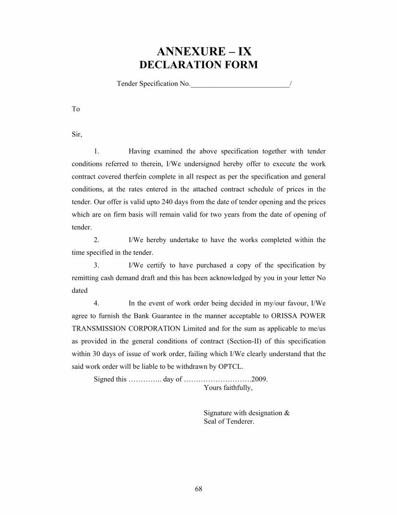
68
ANNEXURE – IX DECLARATION FORM
Tender Specification No.___________________________/
To
Sir,
1. Having examined the above specification together with tender
conditions referred to therein, I/We undersigned hereby offer to execute the work
contract covered therfein complete in all respect as per the specification and general
conditions, at the rates entered in the attached contract schedule of prices in the
tender. Our offer is valid upto 240 days from the date of tender opening and the prices
which are on firm basis will remain valid for two years from the date of opening of
tender.
2. I/We hereby undertake to have the works completed within the
time specified in the tender.
3. I/We certify to have purchased a copy of the specification by
remitting cash demand draft and this has been acknowledged by you in your letter No
dated
4. In the event of work order being decided in my/our favour, I/We
agree to furnish the Bank Guarantee in the manner acceptable to ORISSA POWER
TRANSMISSION CORPORATION Limited and for the sum as applicable to me/us
as provided in the general conditions of contract (Section-II) of this specification
within 30 days of issue of work order, failing which I/We clearly understand that the
said work order will be liable to be withdrawn by OPTCL.
Signed this ………….. day of ……………………….2009. Yours faithfully, Signature with designation & Seal of Tenderer.
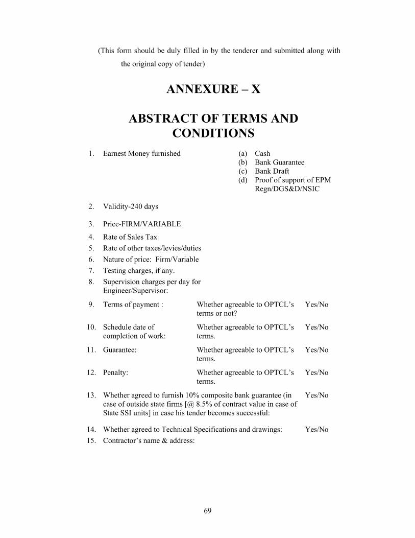
69
(This form should be duly filled in by the tenderer and submitted along with
the original copy of tender)
ANNEXURE – X
ABSTRACT OF TERMS AND CONDITIONS
1. Earnest Money furnished (a) Cash (b) Bank Guarantee (c) Bank Draft (d) Proof of support of EPM
Regn/DGS&D/NSIC
2. Validity-240 days
3. Price-FIRM/VARIABLE
4. Rate of Sales Tax 5. Rate of other taxes/levies/duties 6. Nature of price: Firm/Variable 7. Testing charges, if any. 8. Supervision charges per day for
Engineer/Supervisor:
9. Terms of payment : Whether agreeable to OPTCL’s terms or not?
Yes/No
10. Schedule date of completion of work:
Whether agreeable to OPTCL’s terms.
Yes/No
11. Guarantee: Whether agreeable to OPTCL’s terms.
Yes/No
12. Penalty: Whether agreeable to OPTCL’s terms.
Yes/No
13. Whether agreed to furnish 10% composite bank guarantee (in case of outside state firms [@ 8.5% of contract value in case of State SSI units] in case his tender becomes successful:
Yes/No
14. Whether agreed to Technical Specifications and drawings: Yes/No 15. Contractor’s name & address:

70
SIGNATURE OF TENDERER
NAME: & DESIGNATION:
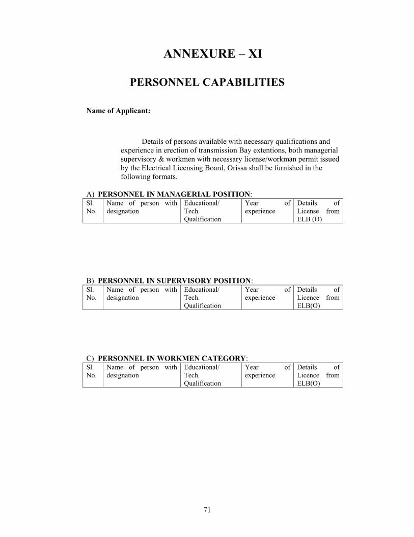
71
ANNEXURE – XI
PERSONNEL CAPABILITIES
Name of Applicant:
Details of persons available with necessary qualifications and experience in erection of transmission Bay extentions, both managerial supervisory & workmen with necessary license/workman permit issued by the Electrical Licensing Board, Orissa shall be furnished in the following formats.
A) PERSONNEL IN MANAGERIAL POSITION: Sl. No.
Name of person with designation
Educational/ Tech. Qualification
Year of experience
Details of License from ELB (O)
B) PERSONNEL IN SUPERVISORY POSITION: Sl. No.
Name of person with designation
Educational/ Tech. Qualification
Year of experience
Details of Licence from ELB(O)
C) PERSONNEL IN WORKMEN CATEGORY: Sl. No.
Name of person with designation
Educational/ Tech. Qualification
Year of experience
Details of Licence from ELB(O)
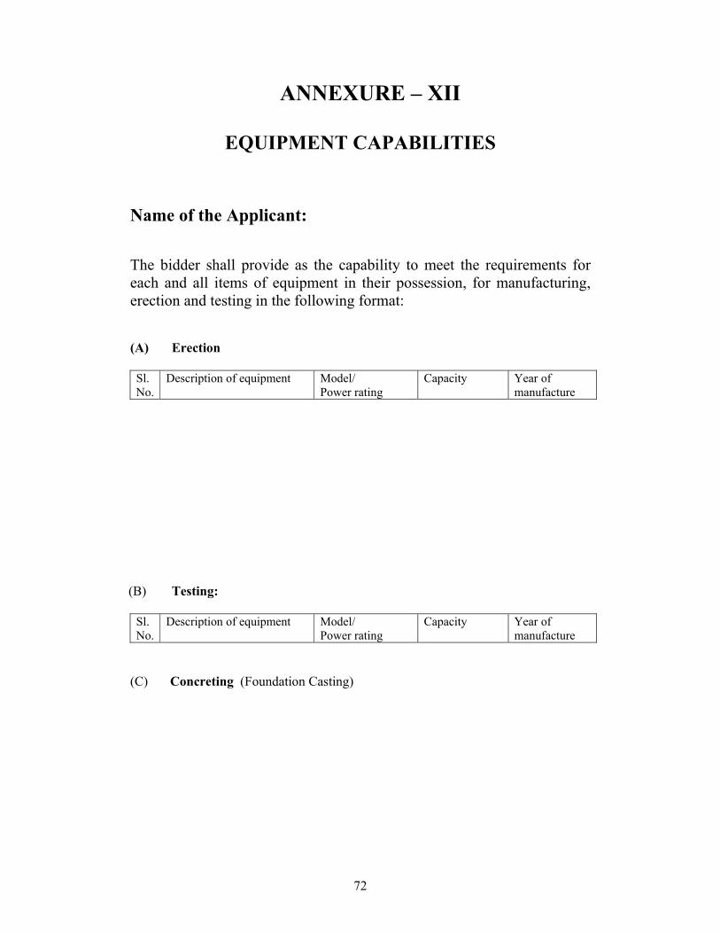
72
ANNEXURE – XII
EQUIPMENT CAPABILITIES
Name of the Applicant: The bidder shall provide as the capability to meet the requirements for each and all items of equipment in their possession, for manufacturing, erection and testing in the following format: (A) Erection Sl. No.
Description of equipment Model/ Power rating
Capacity Year of manufacture
(B) Testing:
Sl. No.
Description of equipment Model/ Power rating
Capacity Year of manufacture
(C) Concreting (Foundation Casting)
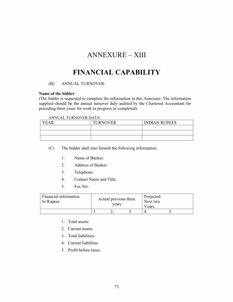
73
ANNEXURE – XIII
FINANCIAL CAPABILITY
(B) ANNUAL TURNOVER:
Name of the bidder: (The bidder is requested to complete the information in this Annexure. The information supplied should be the annual turnover duly audited by the Chartered Accountant for preceding three years for work in progress or completed).
ANNUAL TURNOVER DATA:
YEAR TURNOVER INDIAN RUPEES
(C) The bidder shall also furnish the following information:
1. Name of Banker:
2. Address of Banker:
3. Telephone:
4. Contact Name and Title:
5. Fax No- Financial information In Rupees Actual previous three
years
Projected: Next two Years:
1. 2. 3. 4. 5.
1. Total assets:
2. Current assets:
3. Total liabilities:
4. Current liabilities
5. Profit before taxes:
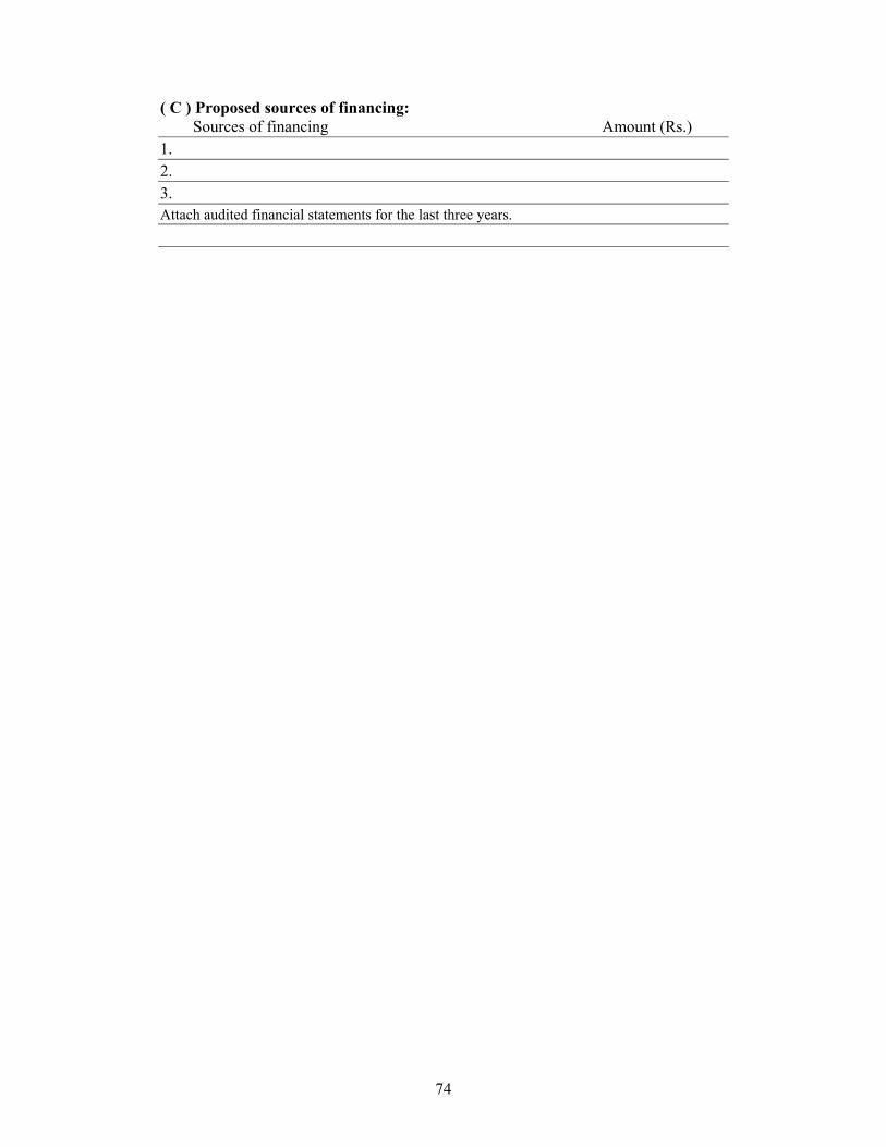
74
( C ) Proposed sources of financing: Sources of financing Amount (Rs.) 1. 2. 3. Attach audited financial statements for the last three years.

75
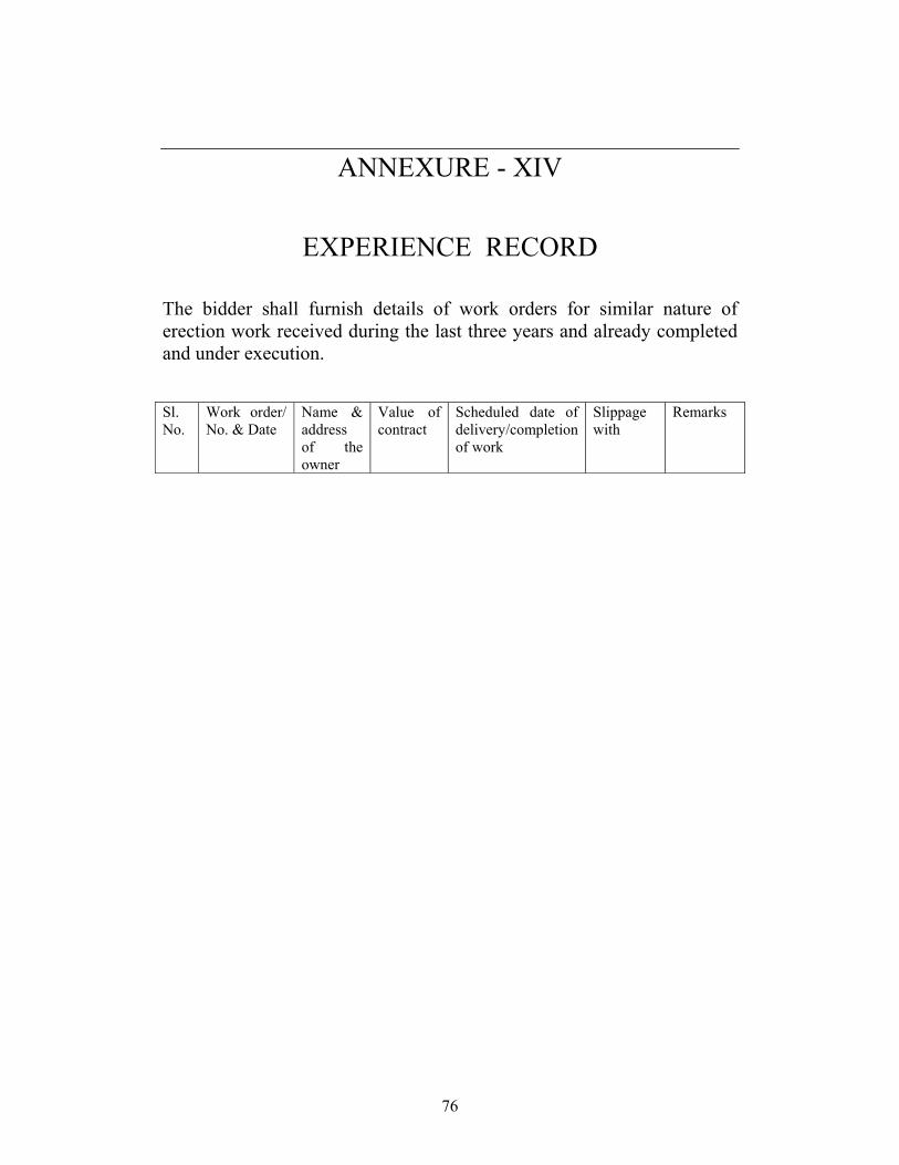
76
ANNEXURE - XIV
EXPERIENCE RECORD
The bidder shall furnish details of work orders for similar nature of erection work received during the last three years and already completed and under execution. Sl. No.
Work order/ No. & Date
Name & address of the owner
Value of contract
Scheduled date of delivery/completion of work
Slippage with
Remarks
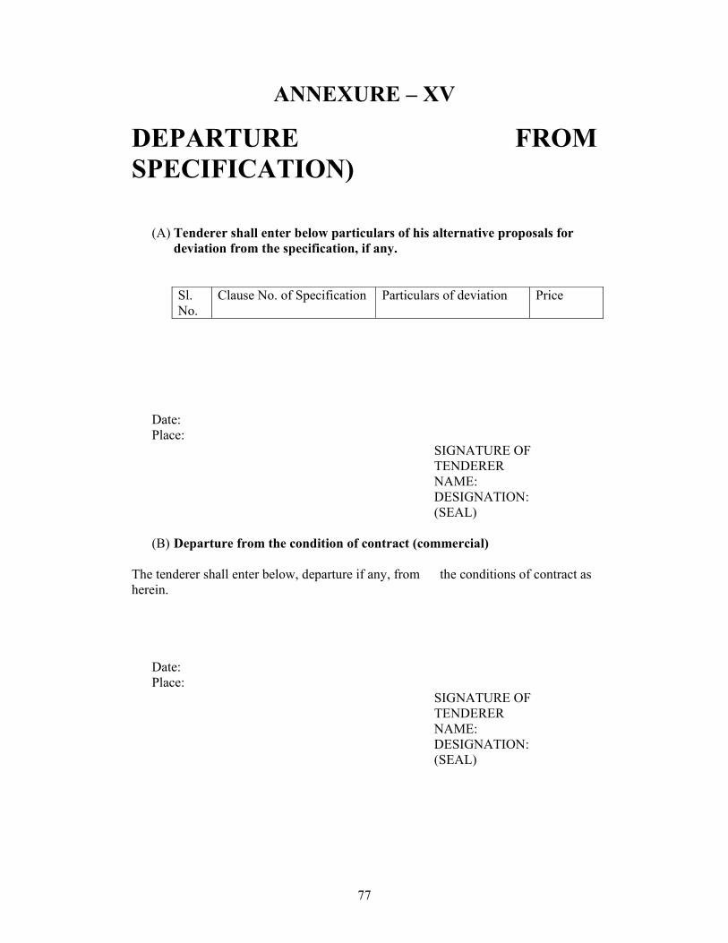
77
ANNEXURE – XV
DEPARTURE FROM SPECIFICATION)
(A) Tenderer shall enter below particulars of his alternative proposals for deviation from the specification, if any.
Sl. No.
Clause No. of Specification Particulars of deviation Price
Date: Place:
SIGNATURE OF TENDERER NAME: DESIGNATION: (SEAL)
(B) Departure from the condition of contract (commercial)
The tenderer shall enter below, departure if any, from the conditions of contract as herein.
Date: Place:
SIGNATURE OF TENDERER NAME: DESIGNATION: (SEAL)
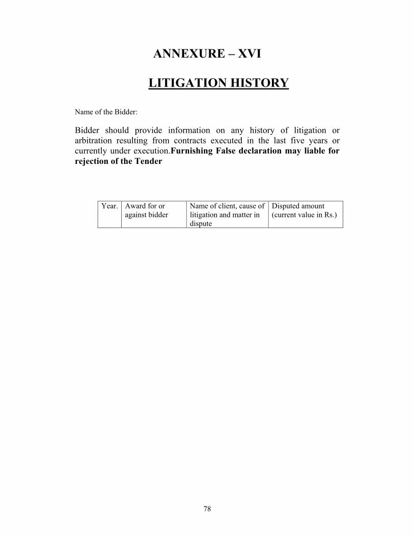
78
ANNEXURE – XVI
LITIGATION HISTORY
Name of the Bidder: Bidder should provide information on any history of litigation or arbitration resulting from contracts executed in the last five years or currently under execution.Furnishing False declaration may liable for rejection of the Tender
Year. Award for or against bidder
Name of client, cause of litigation and matter in dispute
Disputed amount (current value in Rs.)
79
TECHNICAL SPECIFICATIONS
IMPORTANT NOTE
The participants are advised to visit the sites before quoting for the Bid. They should ascertain the volume of filling and height of foundation to be raised since the foundations are inclusive of cost for equipment and structurals for the Sub- Station.
GENERAL
The entire works are covered as Package-I,II are to be carried out on turn-key basis upto final commissioning of the diversion work with Design, manufacture, testing and supply of all materials for both the works including erection, testing and commissioning
3.0 ELECTRICAL WORKS: (Materials to be supplied as per the Price schedule for Both diversion of Lines)
1. Supply of all structurals for the transmission line 2. ACSR Zebra and Panther Conductor 3. Disc Insulators 4. Transmission line Hardwares for Conductor and Earth
Wire 5. 7/3.15 mm GI Groundwire 6. GI Bolts and Nuts 7. GI washers
80
8. Tower Accessaries etc
MAKE OF MAJOR MATERIALS 1.Tower Structures- from the manufactures who are OPTCL rate Contract holders or Reputed make to be approved by OPTCL 2. Insulator-BHEL/WS/Birla NGK/Modern Insulators 3. Hard wares- Eritech/ Rashraudyog/IAC or or any reputed
make to be approved by OPTCL. 4. Earth wire-UIC Wires/Bharat wire Ropes or any reputed
make to be approved by OPTCL. 5. GI Bolts and Nuts-Nexo/Duroplast/BRK Industries 6. Cement-ACC/Ultra Tech or reputed make to be approved
by OPTCL. 7. Steel-TATA/SAIL or reputed make to be approved by
OPTCL. 8. All Civil Engineering Materials- reputed make to be
approved by OPTCL.
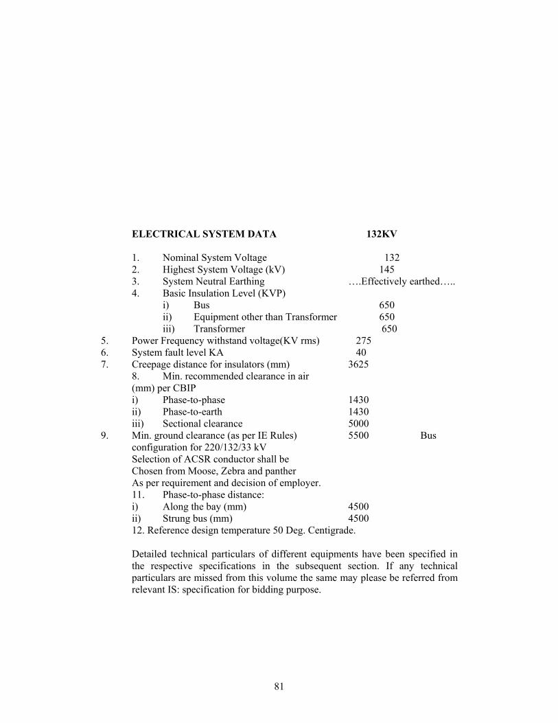
81
ELECTRICAL SYSTEM DATA 132KV 1. Nominal System Voltage 132 2. Highest System Voltage (kV) 145 3. System Neutral Earthing ….Effectively earthed….. 4. Basic Insulation Level (KVP)
i) Bus 650 ii) Equipment other than Transformer 650 iii) Transformer 650
5. Power Frequency withstand voltage(KV rms) 275 6. System fault level KA 40 7. Creepage distance for insulators (mm) 3625
8. Min. recommended clearance in air (mm) per CBIP i) Phase-to-phase 1430 ii) Phase-to-earth 1430 iii) Sectional clearance 5000
9. Min. ground clearance (as per IE Rules) 5500 Bus configuration for 220/132/33 kV Selection of ACSR conductor shall be Chosen from Moose, Zebra and panther As per requirement and decision of employer. 11. Phase-to-phase distance: i) Along the bay (mm) 4500 ii) Strung bus (mm) 4500 12. Reference design temperature 50 Deg. Centigrade.
Detailed technical particulars of different equipments have been specified in the respective specifications in the subsequent section. If any technical particulars are missed from this volume the same may please be referred from relevant IS: specification for bidding purpose.
82
DESIGN WORK
The Bidder shall furnish detailed design of the substation. The design work shall include but not limited to technical calculations, preparation of drawings and bill of materials and specifying equipments not specified in the specification but necessary for the completion of the substation on the turnkey basis. The technical calculation design drawings, etc. shall be submitted to the Employer for approval.
STANDARDS
All materials and equipments shall generally comply in all respects with the latest edition of the relevant Indian Standards. International Electro-Technical Commission (IEC) or any other Internationally accepted Standard equivalent or better than relevant Indian Standard. Equipment complying with all other authoritative standards such as British, ASA, VDE, etc. will also be considered if performance equivalent or superior to Indian Standard is ensured.
In the event of supply of equipment confirming to any International or Internationally recognized Standard other than the Standard listed in the Specification. The salient features of comparison shall be brought out and furnished along with the bid.
In case of adopting any standard other than that IS or IEC, a complete set of adopted standard shall be supplied by the bidder. However it is desirable and preferred that the equipment offered shall comply with one consistent set of standard unless other than exceptional cases.
The equipment shall also comply with the latest revision of Indian Electricity Act and Indian Electricity Rules and any other Electrical Statutory Provision, Rules and Regulations.
REFERENCE DRAWINGS
Drawings showing indicating scope of work are enclosed in Section-7. Drawings are complementary to specifications and shall be r3eferred to for better understanding as well as for estimation of quantities and bill of materials for arising at lump sum bid price on turnkey basis.
The bidder shall submit with the tender, all the drawings quadru0plicate enumerated in conformity with relevant cause stipulated in the Technical Section.
These drawings shall show proposed layout plan with section. Drawings sufficient overall dimension, clearance etc. required for assembling and
83
dismantling and space requirements of all the apparatus to be supplied to enable the Employer to examine the design and layout at the installation.
PACKING AND MARKING
The bidder shall include and provide for securely protecting and packing the plant so as to avoid damage in transit under proper condition and shall be responsible for all loss or damage caused by any defect in packing.
Large and heavy items such as 33kV and 132 kV equipments and structural steel shall be packed and shipped as per standard international practice.
Container/Cartoons, boxes, trunks and other packages shall be strong and sturdy in construction to withstand Ocean shipping. Several times loading and unloading at ports, transport on rough roads, storage in tropical area and hauling and handling during erection etc. Boxes and packages shall also be protected by suitable lagging or galvanized steel strips.
A layer of water proof material shall be provided inside the cartoon/boxes/packages to protect the equipment from water seepage and to avoid rust.
The following information shall be marked on the container/boxes/packages etc.
i) Contractor’s/manufacturer’s name, project title and contract
reference. ii) Plant/accessory identification No. and title. iii) Net/gross weight. iv) Employer’s name with other dispatch particulars such as
destination.
The employer shall take no responsibility for any damage done to the plant on route to the site of work or place of delivery whichever is applicable.
TEST
a) Unless otherwise specified in respective section, all equipment shall be subjected routine and type test as covered and specified in any standard in presence of the authorized representative of the employer.OPTCL may not insist for Type test if the equipments are type tested within last five years but the firms shall furnish the type test cost of the eqipment separately.
b) Bidder shall submit type test report from a recognized laboratory along with the bid.
c) At least 15 days advance notice shall be given by the
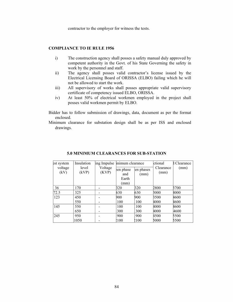
84
contractor to the employer for witness the tests.
COMPLIANCE TO IE RULE 1956
i) The construction agency shall posses a safety manual duly approved by competent authority in the Govt. of his State Governing the safety in work by the personnel and staff.
ii) The agency shall posses valid contractor’s license issued by the Electrical Licensing Board of ORISSA (ELBO) failing which he will not be allowed to start the work.
iii) All supervisory of works shall posses appropriate valid supervisory certificate of competency issued ELBO, ORISSA.
iv) At least 50% of electrical workmen employed in the project shall posses valid workmen permit by ELBO.
Bidder has to follow submission of drawings, data, document as per the format
enclosed. Minimum clearance for substation design shall be as per ISS and enclosed
drawings.
5.0 MINIMUM CLEARANCES FOR SUB-STATION inimum clearance est system
voltage (kV)
c Insulation level (kVP)
hing Impulse Voltage (KVP)
een phase and
Earth (mm)
een phases (mm)
ctional Clearance
(mm)
d Clearance (mm)
36 170 - 320 320 2800 3700 72.5 325 - 630 630 3000 4000 123 450
550 - -
900 1100
900 1100
3500 4000
4600 4600
145 550 650
- -
1100 1300
1100 1300
4000 4000
4600 4600
245 950 1050
- -
1900 2100
1900 2100
4500 5000
5500 5500

85
86
CONDUCTORS
87
TECHNICAL SPECIFICATION OF ACSR ‘ZEBRA’ CONDUCTORS FOR 132 KV BUSBAR
1. SCOPE :-
1.1. This specification provides for the manufacture, testing,
supply and delivery at destination of the steel cored aluminum conductors as
per Appendix-I attached.
2. STANDARDS :-
2.1 The conductors shall comply in all respects with the INDIAN
Standard Specification International/standards with latest amendments. Some
of the standards are
i) IS 398 - Specification for Aluminum Conductors for
overhead transmission purposes,
IS 398, Part-II-1976 -
ii) IS 1521, 1972 - Method of tensile testing of steel
iii) IS 1778 -1989 - Reedurms for bare conductors.
3. MATERIALS :-
3.1 The material offered shall be of best quality and workmanship.
The steel Cored Aluminum conductor strands will consist of hard-drawn
aluminum wire manufactured from 99.5% pure electrolytic aluminum rods of
E.C. Grade. The steel wire shall be made from materials produced either by
the acid or basic open hearth process or by electric process. No steel wire
drawn from pessemer process shall be used. The steel wire shall not contain
88
sulphur or phosphorus exceeding 0.05 percent, and the total of sulphur and
phosphorus shall not exceed 0.085 percent.
3.2 The steel wires shall be evenly and uniformly coated with zinc
complying with Indian Standard 4826-1968 specification for galvanized
coatings on round steel wires. The uniformity of zinc coating and the weight of
coating shall be in accordance with Appendix-II. The coating on the
galvanized steel wires may be applied by the hot process or the electrolytic
process.
4. SIZES :-
4.1 The size of steel-cored Aluminum Conductors shall be as given
in Appendix-I. The resistance and weights shall be in accordance with the
values given in the same appendix.
5. TOLERANCES :-
5.1 The following tolerances shall be permitted on standard
diameter of aluminum wires.
Tolerance on standard diameter of aluminum wire + 1 percent.
wires.
Note : - The cross-section of any wire shall not
depart from circularity by more than an
amount corresponding to a tolerance of
2 percent on the standard diameter.
5.2 A tolerance of + 2 percent shall be permitted on the standard diameter
of the galvanized steel wires. The variation from the approximate
weights shall not be more than plus or minus 5 percent.
6. MECHANICAL PROPERTIES : -
6.1 The value of the final modules of elasticity for steel cored
89
aluminum conductor in the average of values obtained from actual stress
strain tests. The co-efficient of linear expansion for steel Cored Aluminum
Conductors has been calculated on the basis of co-efficient of linear
expansion of 23.0 x 10⁻⁶ per degree centigrade of aluminum and 11.5 x 10⁻⁶
per degree centigrade for steel and represent only the average values. These
values shall however, be given by the bidder under the guaranteed technical
particulars.
7. SURFACE CONDITIONS :-
7.1 The wires shall be smooth and free from inequalities, spills and
splits. The surface conductor shall be free from points, sharp-edges,
abrasions or other departures from smoothness or uniformity of surface
contour that would increase radio interference and corona losses. When
subjected to tension up to 50% of the ultimate strength of the conductor, the
surface shall not depart from its cylindrical form nor any part of the
component, parts or strands, move relative to each other in such a way as to
get out of place and disturb the longitudinal smoothness of the conductor.
8. JOINTS IN WIRES : -
8.1 Aluminum wires : No joints shall be permitted in the aluminum
wires in the outermost layer of the ACSR conductor. Joints in the inner layers
are permitted, in addition to those made in the base rod or wire before final
drawing, but no two such joints shall be less than 15 meter. apart in the
complete stranded conductor. Such joints shall be made by cold pressure
butt-welding.
Joints are not permitted in the outermost layer of the conductor in order
90
to ensure a smooth conductor finish and reduce radio interference levels and
corona losses on the extra high voltage lines.
8.2 Galvanized steel wires : - There shall be no joints except those
in the base rod or wire before final drawing, in steel wires forming the core of
the steel-reinforced aluminum conductor.
Joints have not been permitted in the steel wires after final drawing in
order to avoid reduction in the breaking strength of the conductor that may
occur as a result of failure of the joints.
9. STRANDING :-
9.1 The wires used in construction of a stranded conductor shall
before stranding, satisfy all requirements of IS-398/ (part-II)1976 with latest
amendments. For steel-cored aluminum conductors the lay ratio of the
different layers shall be within the limits given under Appendix-I.
9.2 For all, constructions, each alternate layer shall be stranded in
opposite directions. The wires in each layer shall be evenly and closely
stranded round the under laying wire or wires. The final layer of wires shall
have a right hand lay.
10. PACKING AND MARKING : -
10.1 The conductor shall be wound in non-returnable reels or drums
conforming to Indian Standard 1978-1961 specification for Reels and Drums
for Bare Wire, or any other authoritative standard and marked with the
following : -
a) Trade name, if any b) Contract/Award letter Number
91
c) Name of manufacturer d) Name & Address of Consignee
e) Drum Number f) Length of conductor
g) Size of conductor h) Gross Weight of drum with conductor
i) Weight of empty drum j) Net and gross of conductor.
with lagging. k) Arrow marking of un-winding
10.2 The reel shall be of such construction as to assure delivery of conductor in the field from displacement and damage and should be able to withstand all stresses due to handling and the stringing operations so that conductor surface is not dented, scratched or damaged in any way during manufacture, transport and erection. The conductor shall be properly lagged on the drums and the method of lagging to be employed may be clearly stated in the tender. It should be stocked to suit the reel and held in place by steel strapping. Lagging shall not be nailed or bolted in place. 10.3 The conductor drum should be suitable for wheel mounting.
Before reeling, the card-board or other suitable material shall be secured to
the drum and inside flanges of the drums. After reeling the conductor, the
exposed surfaces should be wrapped with suitable soft material to prevent the
conductor from dirt and grit. Any space between the drum lagging and
conductor should be suitably filled with soft filler material compactly packed.
11. LENGTHS : -
11.1 The conductor shall be supplied in the standard lengths
as below with a permitted variation of 5%. Not less than 90% of the total
quantity of the conductor shall be supplied in the standard lengths. Thus the
quantity of the conductor in lengths shorter than standard ones shall not
exceed 10% of the total quantity to be supplied. Further no single conductor
lengths in respect of such 10% (Maximum supply) in random lengths, shall be
shorter than 50% of the standard lengths.
92
Type of conductor Length per drum.
ZEBRA ACSR 1.1 K.M.
PANTHOR ACSR 2.2 K.M.
12. TESTS AND TEST CERTIFICATES :-
12.1 Individual wire and finished steel cored Aluminum Conductor shall be
subjected to before dispatch from the works to the tests as per the provision of
the Indian standard Specification 395 (Part-II-1976) with the latest
amendments.
12.2 Samples for individual wires for test shall be taken before stranding
form not less than 10 percent of the spiels in the case of aluminum wire and
ten percent of the wire coils in the case of steel wires. If samples are taken
after stranding, they shall be obtained by cutting 5 meters from the outer end
of the finished conductor from not more than 10 percent of the finished reels.
12.3 The mechanical tests shall be carried out on single wires only.
12.4 The Tensile test shall apply to wires of all diameters forming part of
steel cored aluminum conductors. If it is not possible to test the component
wires before stranding the test may be made on wires taken from stranded
conductors. The tensile strength of any of the wires shall not be less than the
minimum values given in Appendix-II.
12.5 A suitable tensile testing machine shall be used the accuracy of which
can easily be checked and the machine adjusted if necessary. The test
sample before being placed in the machine, shall be straightened, if
necessary in such a way as to cause the minimum alteration in its physical
properties.
93
The load shall be applied gradually and rate of separation of the Jaws
of the testing machine shall not be greater than 10cm/min. and less than
2.5cm/min.
12.6 Wrapping Test : -
12.6.1 Samples of aluminium wires shall be wrapped round a
wire of its own diameter to form a close helix of eight turns. Six turns shall
then be unwrapped and again clearly wrapped in the same direction as
before. The wire shall not break.
12.6.2 Samples of steel wires shall be closely wrapped eight
times round a mandrel of diameter equal to four times the wire diameter. Six
turns shall then be unwrapped and again closely wrapped in the same
direction as before. The wire shall not break.
12.7 Galvanizing Test : -
12.7.1 The uniformity of zinc coating and the weight of coating shall be
as given in Appendix-II and shall be determined according to Indian Standard
Specification 4826-1968. with latest amendments.
12.7.2 This test shall be made whenever practicable, on wires before stranding and before the specimen has been bent, straightened or tested in any other way.
12.8 Ductility Test : -
This test shall be made on galvanized steel wires only by any of the
proceedings given in 12.8.1 and 12.8.2.
12.8.1 Torsion Test : - One specimen cut from each of the sample shall be
gripped at its ends in two vices, one of which shall be free to move
longitudinally during the test. A small tensile bond not exceeding 2% of the
94
breaking load of the wire, shall be applied to the sample during testing. The
specimen shall be twisted by consisting one of the vices to revolve until
fracture occurs and the number of twists shall be indicated by a counter or
other suitable device. The rate of twisting shall not exceed 60 rev/min.
When tested before stranding, the number of complete twists before
fracture occurs shall not be less than 18 on a length equal to 100 times the
diameter of the wire. The fracture shall show a smooth surface at right angles,
to the axis of the wire.
When tested after stranding, the number of complete twists
before fracture occurs shall be not less than 16 on a length equal to 100 times
the diameter of the wire. The fracture shall show a smooth surface at right
angles to the axis of the wire.
12.8.2 Elongation Test : - The elongation of one specimen cut from
each of the samples shall be determined. The specimen shall be straightened
by hand and on original gauge length of 200 mm shall be marked on the wire.
A tensile load shall be applied as described in 12.5 and the elongation shall
be measured after the fractured ends fitted together. If the fracture occurs
outside the gauge marks, or within 25mm of either mark and the required
elogation is not obtained, the test shall be disregarded and another test made.
When tested before stranding, the elongation shall be not less than 4 percent.
When tested after stranding, the elongation shall be not less than 3.5 percent.
12.9 Surface Condition Test
A sample of the finished conductor having a minimum recommended
length of 5 meters with compression type dead end clamps compressed on
95
both ends in such a manner as to permit the conductor to take its normal
straight line shape, shall be subject to a tension of 50% of the UTS of the
conductor. The surface shall not depart from its cylindrical shape nor shall the
strands move relative to each other so as to get out of place of disturb the
longitudinal smoothness of conductor. The measured diameter at any place
shall be not less than the sum of the minimum specified diameters of the
individual aluminum and steel strands.
12.10 Ultimate Strength (UTS) Test on Stranded Conductor
Circles perpendicular to the axis of the conductor shall be
marked at two places on a sample of conductor of minimum 5 m length
suitably compressed with dead end clamps at either end. The load shall be
increased at a steady rate up to specified 50% of UTS and held for one
minute. The circles drawn shall not be distorted due to Relative movement of
strands. Thereafter the load shall be increased at a steady rate to the
minimum UTS specified in Appendix-I and held for one minute. The applied
load shall then be increased until the failing load is reached and the value
recorded.
12.11 Corona Extinction Voltage Test
One sample of conductor of 5m length shall be strung. In case
of twin conductor, two samples shall be arranged with the actual sub-
conductor spacing between them. This sample assembly when subjected to
power frequency voltage shall have a corona extinction voltage of not less
than 320 KV (rms) for 400 KV and 176 KV (rms) for 220 KV system line to
ground under dry condition. There shall be no evidence of corona on any part
96
of sample when all possible sources of corona are photographed in a
darkened room. The test shall be conducted without corona control rings. The
voltage shall be corrected for standard atmospheric conditions.
12.12 Radio Interference Voltage Test
Under the conditions as specified in 12.11 above, the conductor
samples shall have a radio interference voltage level below 1500 microvolts
at one MHZ when subjected to 50HZ AC voltage of 1.1 times maximum line to
ground voltage under dry condition. This test may be carried out with corona
control rings and arcing horns.
12.13 D.C. Resistance Test on Stranded Conductor
On a conductor sample of minimum 5 m length two contact clamps
shall be fixed with a pre-determined bolt torque. The resistance shall be
measured by a Kelvin double bridge by placing the clamps initially zero meter
and subsequently one meter apart. The test shall be repeated at least five
times and the average value recorded. The value obtained shall be corrected
to the value at 20 degree centigrade as per clause No.12.8 of IS : 398 (part
V). The resistance corrected at 20 degree centigrade shall conform to the
requirements of this specification.
12.14 Stress-Strain Test
12.14 (i)This test is contemplated only to collect the creep data of the
conductor from the supplier. A sample of conductor of minimum 10 metres
length shall be suitably compressed with dead end clamps.
12.14 (ii)Test Set-up
97
12.14 (ii) (a) The test sample shall be supported in a trough over its full
length and the trough adjusted so that the conductor will not be lifted by more
than 10 mm under tension. This shall be ascertained by actual measurement.
12.14 (ii) (b) The distance between the clamp and the sleeve mouth
shall be monitored with callipers during the test to ensure that, after the test, it
does not change by more than 1 mm +/-0.1mm from the value before the test.
12.14 (iii) (c) The conductor strain shall be evaluated from the
measured displacements at the two ends of the gauge length of the sample.
The gauge reference targets shall be attached to the clamps which lock the
steel and aluminum wires together. Target plates may be used with dial
gauges or displacement transducers and care shall be taken to position the
plates perpendicular to the conductor. Twisting the conductor, lifting it and
moving it from side-to-side by the maximum amounts expected during the test
should introduce no more than 0.3mm error in the reading.
12.14 (iii)Test Loads for Complete Conductor
The loading conditions for repeated stress-strain tests for complete
conductor shall be as follows :
12.14 (iii) (a) 1 KN load shall be applied initially to straighten the
conductor. The load shall be removed after straightening and then the strain
gauges are to be set at zero at zero tension.
12.14 (iii) (b) For non-continuous stress-strain data, the strain reading
at 1 KN intervals at lower tensions and 5KN intervals above 30% of UTS shall
be recorded.
98
12.14 (iii) (c) The sample shall be reloaded to 50% of UTS and held for
1 hour. Readings are to be noted after 5, 10, 15, 30, 45 and 60 minutes during
the hold period. The load shall be released after the hold period.
12.14 (iii) (d) Reloading up to 70% of UTS shall be done and held for 1
hour. Readings are to be noted after 5, 10, 15, 30, 45, and 60 minutes and
then the load shall be released.
12.14 (iii) (e) Reloading up to 85% of UTS shall be done and hold for 1
hour. Readings are to be noted after 5, 10, 15, 30, 45 and 60 minutes and
then the load shall be released.
12.14 (iii) (f) Tension shall be applied again and shall be increased
uniformly until the actual breaking strength is reached. Simultaneous readings
of tension and elongation shall be recorded up to 90 % of UTS at the intervals
described under Clause 12.14 (iii) (e).
12.14 (iv)Test Loads for Steel core Only.
The loading conditions for repeated stress-strain tests for the steel core
of ACSR shall be as follows :
12.14 (iv) (a) The test shall consist of successive application of load
applied in a manner similar to that for the complete conductor at 30%, 50%,
70% and 85% of UTS.
12.14 (iv) (b) The steel core shall be loaded until the elongation at the
beginning of each hold period corresponds to that obtained on the complete
conductor at 30%, 50%, 70% and 85% of UTS respectively.
12.14 (v)Stress Strain Curves
The design stress-strain curve shall be obtained by drawing a smooth
99
curve through the 0.5 and 1 hour points at 30%, 50%, and 70% of UTS loadings. The presence of any aluminum slack that can be related to any observed extrusion entering the span from the compression dead ends shall be removed from the lower ends of the design curves. Both the laboratory and design stress-strain curves shall be submitted to the purchaser along with test results. The stress-strain data obtained during the test shall be corrected to the standard temperature i.e. 20 degree centigrade.
12.15 Chemical Analysis of Zinc
Samples taken from the Zinc ingots shall be chemically/ spectrographically analyzed. The same shall be in conformity to the requirements stated in this specification.
12.16 Chemical Analysis of Aluminum and Steel
Samples taken from the Aluminum ingots/ coils/ strands shall be chemically/ spectrographically analyzed. The same shall be in conformity to the requirements stated in this specification.
12.17 Visual and Dimensional Check on Drums
The drums shall be visually and dimensionally checked to ensure that they conform to the requirements of this specification.
12.18 Visual Check for Joints, Scratches etc.
Conductor drums shall be rewound in the presence of the inspector. The inspector shall visually check for scratches, joints, etc. and that the conductor generally conform to the requirements of this specification.
12.19 Dimensional Check of Steel and Aluminum Strands
The individual strands shall be dimensionally checked to ensure that they conform to the requirements of this specification.
12.20 Check for Lay-ratios of various Layers
The lay-ratios of various layers shall be checked to ensure that they conform to the requirements of this specification.
12.21 Breaking load test on welded Aluminum strand.
Two Aluminum wires shall be welded as per the approved quality plan and shall be subjected to tensile load. The welded point of the wire shall be able to withstand the minimum breaking load of the individual strand guaranteed by the supplier.
100
13. RETEST AND REJECTION : -
13.1 Each coil or spool selected for testing shall be tested for compliance with the requirements of Indian Standard Specification 398 (part-II) 1976 with latest amendment if any selected coil or spool not fulfill any of the test requirements, that particular coil or spool shall be withdrawn. In respect of each failure, two test pieces shall be selected from two different coils in the lot and subjected to the test under which the failure occurred. If either of the two retest pieces fails to pass that test, the lot concerned shall be rejected.
If samples are taken for test after stranding and if any selected
reel fails in the retest, the manufacturer may test each and every reel
and submit them for further inspection. All rejected materials shall be
suitably marked and segregated.
14. GUARANTEED TECHNICAL PARTICULARS : -
The bidder shall fill in the guaranteed technical particulars in the
Performa at Appendix-IV and submit the same with his tender, without
which bid will not be considered.
15. SAG TENSION CHARTS AND SAG TEMPLATES : -
The contractor shall supply each six copies of sag tension charts
and sag templates in respect of each type of the steel core aluminum
conductor. The Contractor shall also supply sag template in celluloid
which shall be subject to the approval by the purchaser and without
involving any extra charges. The design data of the lines on which
these conductors will be used are given in Appendix-III.

101
102
A P P E N D I X - I ZEBRA ACSR 1. Size of conductor 54/7/3.18 mm
2. Stranding and wire diameter
Aluminum 54/3.18 mm
Steel 7/3.18 mm
3. Nominal Aluminum Area 428.9 mm2
4. Approximate total mass 1622 Kgs/KM
5. Calculated resistance at 20°C Max. 0.06915 Ohms/Km.
6. Calculated breaking load of 13289 Kg.
composite conductor
(U.T.S.) (Min)
7. Lay Rating :-
Steel core Max - 28
Min - 13
Aluminium Layers
12 Wire Layer Max - 17
(Innermost Layer) Min - 10
18 Wire Layer Max - 16
(Lay immediately beneath outside Layer) Min - 10
24 wire layer (outside layer) Max - 14
Min - 10
8. Modulus of elasticity 0.7036 x 10⁶ Kg x CM2
9. Co-efficient of linear expansion 19.3 x 10⁻⁶C
of conductor.
10. Standard area of Cross Section in 484.5 mm2
Sq. mm of conductor.
103
11. Diameter of complete conductor in 28.62 mm
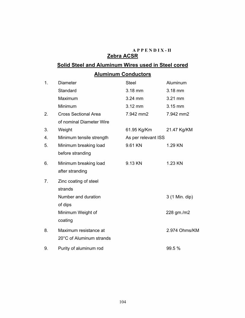
104
A P P E N D I X - II Zebra ACSR
Solid Steel and Aluminum Wires used in Steel cored
Aluminum Conductors 1. Diameter Steel Aluminum
Standard 3.18 mm 3.18 mm
Maximum 3.24 mm 3.21 mm
Minimum 3.12 mm 3.15 mm
2. Cross Sectional Area 7.942 mm2 7.942 mm2
of nominal Diameter Wire
3. Weight 61.95 Kg/Km 21.47 Kg/KM
4. Minimum tensile strength As per relevant ISS
5. Minimum breaking load 9.61 KN 1.29 KN
before stranding
6. Minimum breaking load 9.13 KN 1.23 KN
after stranding
7. Zinc coating of steel
strands
Number and duration 3 (1 Min. dip)
of dips
Minimum Weight of 228 gm./m2
coating
8. Maximum resistance at 2.974 Ohms/KM
20°C of Aluminum strands
9. Purity of aluminum rod 99.5 %
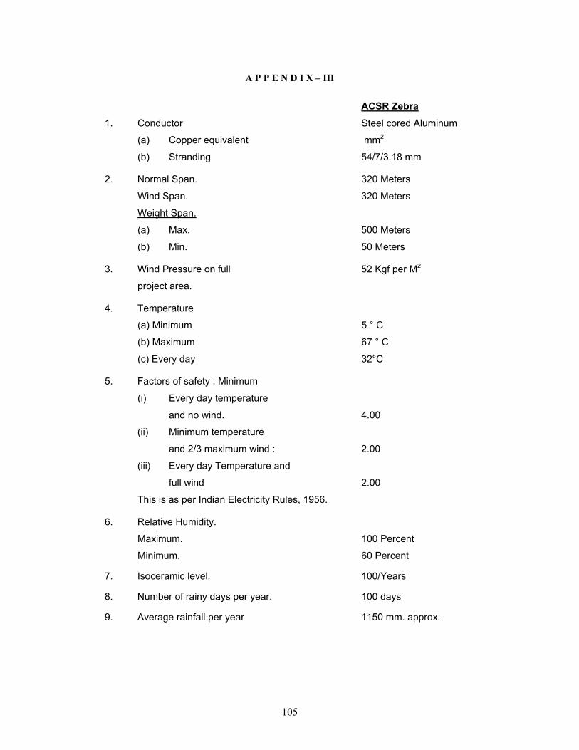
105
A P P E N D I X – III
ACSR Zebra 1. Conductor Steel cored Aluminum
(a) Copper equivalent mm2
(b) Stranding 54/7/3.18 mm
2. Normal Span. 320 Meters
Wind Span. 320 Meters
Weight Span.
(a) Max. 500 Meters
(b) Min. 50 Meters
3. Wind Pressure on full 52 Kgf per M2
project area.
4. Temperature
(a) Minimum 5 ° C
(b) Maximum 67 ° C
(c) Every day 32°C
5. Factors of safety : Minimum
(i) Every day temperature
and no wind. 4.00
(ii) Minimum temperature
and 2/3 maximum wind : 2.00
(iii) Every day Temperature and
full wind 2.00
This is as per Indian Electricity Rules, 1956.
6. Relative Humidity.
Maximum. 100 Percent
Minimum. 60 Percent
7. Isoceramic level. 100/Years
8. Number of rainy days per year. 100 days
9. Average rainfall per year 1150 mm. approx.
106
10. Altitude. Less than 350 Metres
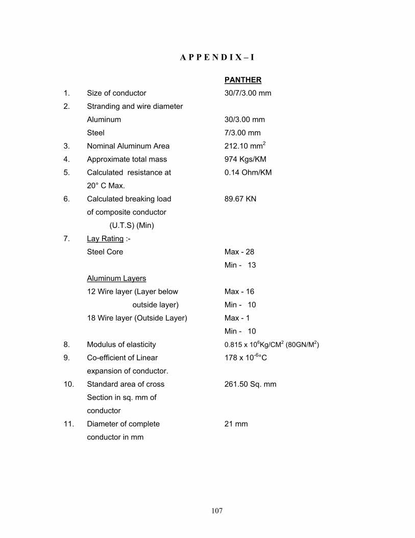
107
A P P E N D I X – I
PANTHER 1. Size of conductor 30/7/3.00 mm
2. Stranding and wire diameter
Aluminum 30/3.00 mm
Steel 7/3.00 mm
3. Nominal Aluminum Area 212.10 mm2
4. Approximate total mass 974 Kgs/KM
5. Calculated resistance at 0.14 Ohm/KM
20° C Max.
6. Calculated breaking load 89.67 KN
of composite conductor
(U.T.S) (Min)
7. Lay Rating :-
Steel Core Max - 28
Min - 13
Aluminum Layers
12 Wire layer (Layer below Max - 16
outside layer) Min - 10
18 Wire layer (Outside Layer) Max - 1
Min - 10
8. Modulus of elasticity 0.815 x 10⁶Kg/CM2 (80GN/M2)
9. Co-efficient of Linear 178 x 10-6°C
expansion of conductor.
10. Standard area of cross 261.50 Sq. mm
Section in sq. mm of
conductor
11. Diameter of complete 21 mm
conductor in mm
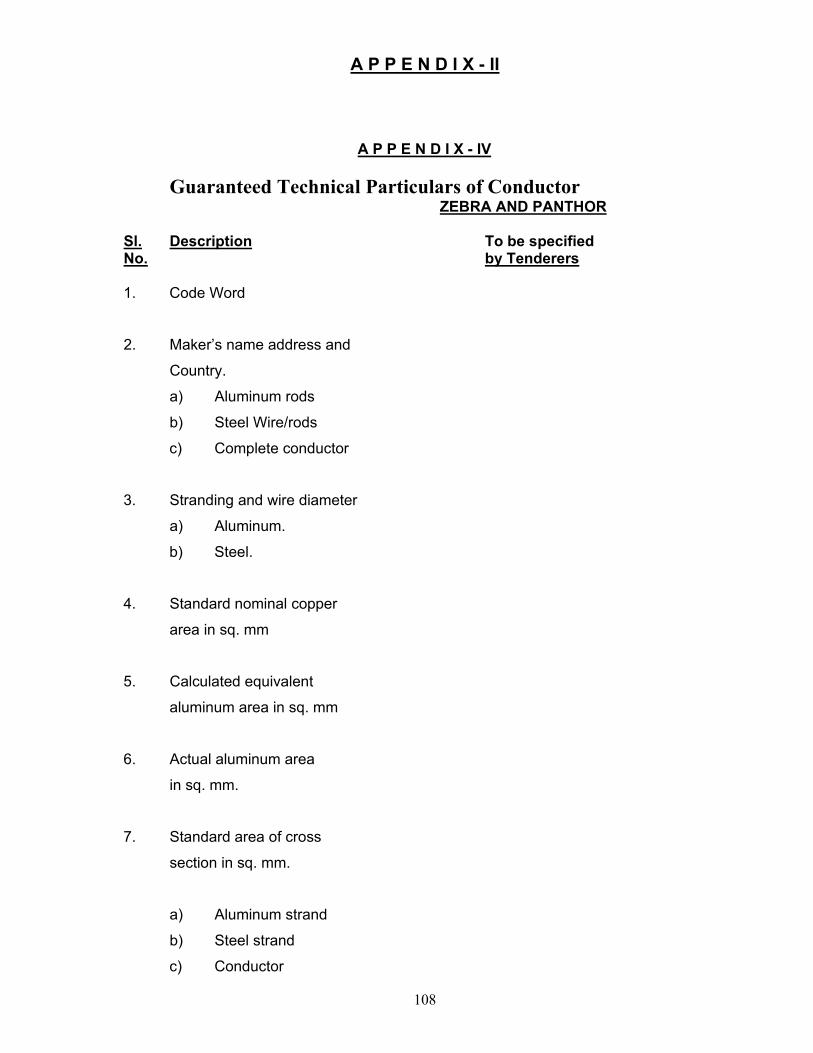
108
A P P E N D I X - II
A P P E N D I X - IV
Guaranteed Technical Particulars of Conductor ZEBRA AND PANTHOR
Sl. Description To be specified No. by Tenderers 1. Code Word
2. Maker’s name address and
Country.
a) Aluminum rods
b) Steel Wire/rods
c) Complete conductor
3. Stranding and wire diameter
a) Aluminum.
b) Steel.
4. Standard nominal copper
area in sq. mm
5. Calculated equivalent
aluminum area in sq. mm
6. Actual aluminum area
in sq. mm.
7. Standard area of cross
section in sq. mm.
a) Aluminum strand
b) Steel strand
c) Conductor
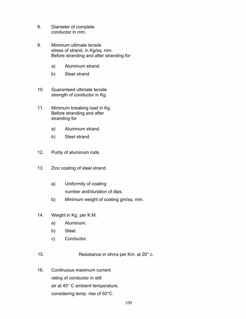
109
8. Diameter of complete conductor in mm.
9. Minimum ultimate tensile stress of strand, in Kg/sq. mm.
Before stranding and after stranding for
a) Aluminum strand.
b) Steel strand
10. Guaranteed ultimate tensile strength of conductor in Kg.
11. Minimum breaking load in Kg. Before stranding and after stranding for a) Aluminum strand.
b) Steel strand.
12. Purity of aluminum rods.
13. Zinc coating of steel strand. a) Uniformity of coating
number and/duration of dips.
b) Minimum weight of coating gm/sq. mm.
14. Weight in Kg. per K.M.
a) Aluminum.
b) Steel.
c) Conductor.
15. Resistance in ohms per Km. at 20° c.
16. Continuous maximum current
rating of conductor in still
air at 45° C ambient temperature,
considering temp. rise of 50°C.
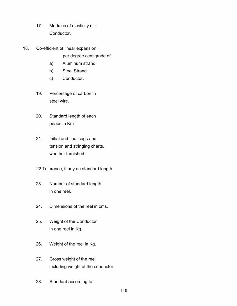
110
17. Modulus of elasticity of :
Conductor.
18. Co-efficient of linear expansion
per degree centigrade of.
a) Aluminum strand.
b) Steel Strand.
c) Conductor.
19. Percentage of carbon in
steel wire.
20. Standard length of each
peace in Km.
21. Initial and final sags and
tension and stringing charts,
whether furnished.
22.Tolerance, if any on standard length.
23. Number of standard length
in one reel.
24. Dimensions of the reel in cms.
25. Weight of the Conductor
in one reel in Kg.
26. Weight of the reel in Kg.
27. Gross weight of the reel
including weight of the conductor.
28. Standard according to
111
which the conductor will
be manufactured and tested.
29. Other particulars, if any.
112
SECTION - XII
TECHNICAL SPECIFICATION
FOR
G.I. GROUND WIRE.
( 7/3.15 MM )
113
TECHNICAL SPECIFICATION OF 7/3.15 mm G.I. EARTH WIRE
1. SCOPE : 1.1 This specification provides for the manufacture, testing before despatch, supply and
delivery of Ground wire for the purpose of earthing and protection of power transmission
line, as per the particulars given in Appendix-I attached. The ground wire shall consist of
standard galvanized steel wire.
2. STANDARDS :
2.1 The ground wire shall comply in all respect with the Indian Standard (IS) 2141-1979
3. MATERIALS :
3.1 The material offered shall be of best quality and workmanship. The steel wires (Strands)
shall be manufactured from steel produced by any suitable process. The steel wire shall not
contain sulphur and phosphorous exceeding 0.060 percent each as per IS : 2141-1971.
3.2 The steel wires shall be evenly and uniformity quoted with zinc complying with IS: 209-
1965 specification for zinc (Retired). Only virgin zinc shall be used and reclaimed zinc is
not permitted. The virgin zinc shall be of zn 99.95 quality.
4. SIZE AND CONSTRUCTION :
4.1 The size of ground wire shall be as given in Appendix-I. The physical properties have been
given in the same Appendix. The lay of the strands shall be of lengths as given in the
Appendices. The wires shall be so stranded together that when any evenly distributed pulls
applied at the end of the completed strands each wire will take on equal share of the pull.
5. LENGTH OF JOINING:
5.1 The ground wire may be supplied in the standard length as per manufacturers standard
practice and such length will be specifically indicated in the tender. However random length
of ground wire upto a maximum of 10 (Ten) percent may be allowed.
5.2 The length of strand which may be supplied without joints in the individual wires
comprising it depends on the length of wire which may be carried by the bobbin in a normal
stranding machine. The normal lengths of strand which shall be supplied without joints in
individual wires, excluding welds made in the rod before drawing shall be as given in
Appendix – I.
5.3 Each coil shall be warranted to contain no weld joints or splice ether than in the rod before
it is drawn and those permitted in 5.3 above. The wire shall be circular and shall be free
from scale or irregularities, imperfections, flow spite and other defects. The zinc coating
shall be smooth even and bright.
6. TESTS AND TEST CERTIFICATES:
6.1 Ground wire shall be subjected to the tests as specified in the IS:2141-1979 before despatch.
114
6.2 Al the coils of the galvanized strand shall be of the same grade, diameter and construction
manufactured under similar condition shall be grounded to constitute one lot.
6.3 Samples from each lot shall be tested for ascertaining the conformity to the requirements of
the ground wire specified herein. The coils selected shall be tested for length of the lay and
joints. The lot shall be declared conforming to the requirements of these characteristics if
all the coils are found satisfactory. One test specimen from each wire of the strand shall be
drawn, from every selected coil and subjected to tensil tests, ductility test and coating test.
One specimen of the completed strand from each coil shall be subjected to tensil strength.
The lot shall be declared conforming to the requirements of these characteristics if the entire
best specimen satisfy the relevant requirements.
6.4 Chemical Analysis : One sample shall be drawn from the lot for chemical analysis. Unless
otherwise agreed to between the purchase and supplier the chemical analysis shall be carried
out.
6.5 Tensile Test : The wire when tested in accordance with IS : 1521-1960 shall have minimum
tensile strength specified in the Appendix – I. The tensile strength of the finished strand
shall not be less than 95% of the aggregate of the single wires.
6.6 Ductility test : The wire shall be subjected to wrapping test in accordance with IS : 1755-
1961. When wrapped eight times round its own diameter and on being subsequently
straightened the wire shall not break or split.
6.7 Coating test : The uniformity of zinc coating shall be tested as per IS: 2633-1964. The wire
shall withstand the number of dips specified in Appendix – I.
6.8 Three copies of manufacturers test certificate shall be submitted by the contractor to the
purchaser for approval immediately after such tests have been conducted on the strands and
the wire.
6.9 The purchaser reserves the right to inspect the material at Manufacturer’s works before
despatch.
7. PACKING AND MARKING :
7.1 The ground wire shall be supplied in non-returnable reals or drums of non-perishable or
treated wood conforming to IS: 1778-1991 specification for Reals and Drums for Bare wire.
Each coil shall be provided with a level fixed firmly on the inner part of the coil, bearing the
following information.
(a) Trade name, if any.
(b) Name of manufacturer
(c) Type of wire, size and length of wire.
(d) Not weight of the wire.
(e) Total weight, and
115
(f) Number of lengths on the real or drum unless otherwise agreed to between the purchaser and the supplier, the stranded wire shall be supplied in 50 Kg. coil.
8. SAG AND TENSION CHARTS AND SAG TEMPLATE :
8.1 The successful tenderer shall be required to submit six copies of sag templates and strings
charts for different temperatures and spans, One set of charts shall be ink on tracing cloth.
The design date of the lines on which the ground wire will be used are given in Appendix –
II.
116
TECHNICAL SPECIFICATION FOR SUB- STATION TOWER NUTS & BOLTS.
1.0 SCOPE: It covers the requirements for hot-dip galvanized hexagon-head
transmission tower bolts with nut and Washers in the size range of M-16 and M-12 for use in the construction of transmission towers, sub-stations &
similar steel structure in Arunachal Power System. The firm must enclose
the dimensional drawings of all bolts, nuts and washers with the bid. 1.1 These bolts are not suitable for applications requiring improved low temperature
characteristics.
2.0 DIMENSION: 2.1 The dimensions of the bolts shall be as given in Table-1 of IS: 12427-1988 2.2 The preferred length size combinations as well as grip ranges shall be as given in
Table-2 of IS:12427-1988 and specification of OPTCL.
2.2 Prior to hot-dip galvanizing, the bolt threads shall confirm to tolerance class 8g of
IS:4218-(Pt.6)-1978. “ISO metric screw threads: Part-6, limit of sizes for
commercial bolts & nuts (Dia Range: 1 to 52mm) (First Revision)”.
3.0 GRADES: Unless otherwise specified, the bolts shall be of product grade ‘C’ as specified in IS: 1367
(Pt.2)-1979 “Technical Supply Conditions for threaded steel fasteners: Part-2,
products grades and tolerances (Second Revision)”.
4. MATING NUTS & WASHERS:
4.1 Unless otherwise specified, the hexagon nuts used with these bolts shall conform to
the requirements of IS:1363 (Part-3)-1984/1992./12427/1988
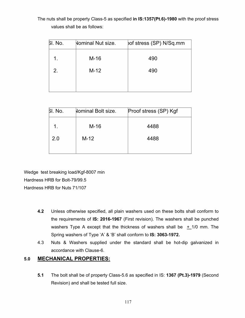
117
The nuts shall be property Class-5 as specified in IS:1357(Pt.6)-1980 with the proof stress
values shall be as follows:
Sl. No. Nominal Nut size. oof stress (SP) N/Sq.mm
1.
2.
M-16
M-12
490
490
Sl. No. Nominal Bolt size. Proof stress (SP) Kgf
1.
2.0
M-16
M-12
4488
4488
Wedge test breaking load/Kgf-8007 min
Hardness HRB for Bolt-79/99.5
Hardness HRB for Nuts 71/107
4.2 Unless otherwise specified, all plain washers used on these bolts shall conform to
the requirements of IS: 2016-1967 (First revision). The washers shall be punched
washers Type A except that the thickness of washers shall be + 1/0 mm. The
Spring washers of Type ‘A’ & ‘B’ shall conform to IS: 3063-1972. 4.3 Nuts & Washers supplied under the standard shall be hot-dip galvanized in
accordance with Clause-6.
5.0 MECHANICAL PROPERTIES: 5.1 The bolt shall be of property Class-5.6 as specified in IS: 1367 (Pt.3)-1979 (Second
Revision) and shall be tested full size.
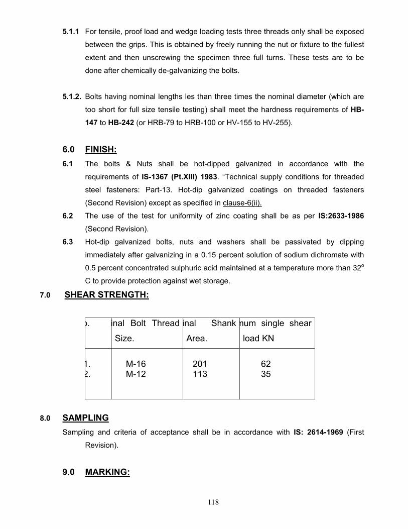
118
5.1.1 For tensile, proof load and wedge loading tests three threads only shall be exposed
between the grips. This is obtained by freely running the nut or fixture to the fullest
extent and then unscrewing the specimen three full turns. These tests are to be
done after chemically de-galvanizing the bolts.
5.1.2. Bolts having nominal lengths les than three times the nominal diameter (which are
too short for full size tensile testing) shall meet the hardness requirements of HB-147 to HB-242 (or HRB-79 to HRB-100 or HV-155 to HV-255).
6.0 FINISH: 6.1 The bolts & Nuts shall be hot-dipped galvanized in accordance with the
requirements of IS-1367 (Pt.XIII) 1983. “Technical supply conditions for threaded
steel fasteners: Part-13. Hot-dip galvanized coatings on threaded fasteners
(Second Revision) except as specified in clause-6(ii).
6.2 The use of the test for uniformity of zinc coating shall be as per IS:2633-1986
(Second Revision).
6.3 Hot-dip galvanized bolts, nuts and washers shall be passivated by dipping
immediately after galvanizing in a 0.15 percent solution of sodium dichromate with
0.5 percent concentrated sulphuric acid maintained at a temperature more than 32o
C to provide protection against wet storage.
7.0 SHEAR STRENGTH:
o. inal Bolt Thread
Size.
inal Shank
Area.
mum single shear
load KN
1. 2.
M-16 M-12
201 113
62 35
8.0 SAMPLING Sampling and criteria of acceptance shall be in accordance with IS: 2614-1969 (First
Revision).
9.0 MARKING:
119
9.1 Transmission tower bolts shall be marked with the following symbols on the top
surface of the bolt head either embossed or indented as given below.
9.1.1. The Manufactures identification symbol.
9.1.2. Transmission tower bolt identification symbol ‘T’.
9.1.3. The minimum height of marking shall be 3.0 mm when embossed marking shall
project and not less than 0.3 mm above the surface of the head and total head
height (head plus marking) shall not exceed the specified maximum head height
plus 0.4 mm.
10.0 TEST:
The test mechanical properties and test method shall be as per IS: 1367 (Part-2/1979,
Part-3/1991, Part-6/1980, Part-XIII/1983) for Transmission Tower Bolts & Nuts.
ROUTINE TESTS TO BE CONDUCTED AT THE MANUFACTURER’S PREMISSES.
Hex Bolt: 12427 – 1988
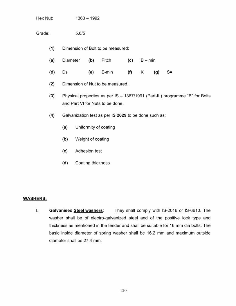
120
Hex Nut: 1363 – 1992
Grade: 5.6/5
(1) Dimension of Bolt to be measured:
(a) Diameter (b) Pitch (c) B – min
(d) Ds (e) E-min (f) K (g) S=
(2) Dimension of Nut to be measured.
(3) Physical properties as per IS – 1367/1991 (Part-III) programme “B” for Bolts
and Part VI for Nuts to be done.
(4) Galvanization test as per IS 2629 to be done such as:
(a) Uniformity of coating
(b) Weight of coating
(c) Adhesion test
(d) Coating thickness
WASHERS:
I. Galvanised Steel washers: They shall comply with IS-2016 or IS-6610. The
washer shall be of electro-galvanized steel and of the positive lock type and
thickness as mentioned in the tender and shall be suitable for 16 mm dia bolts. The
basic inside diameter of spring washer shall be 16.2 mm and maximum outside
diameter shall be 27.4 mm.
121
EARTH WIRE (7/3.15 mm)
GUARANTEED TECHNICAL PARTICULARS
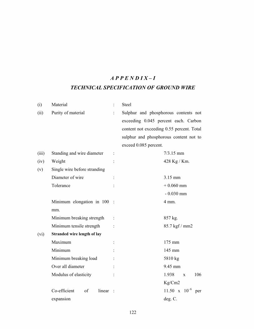
122
A P P E N D I X – I
TECHNICAL SPECIFICATION OF GROUND WIRE
(i) Material : Steel
(ii) Purity of material : Sulphur and phosphorous contents not
exceeding 0.045 percent each. Carbon
content not exceeding 0.55 percent. Total
sulphur and phosphorous content not to
exceed 0.085 percent.
(iii) Standing and wire diameter : 7/3.15 mm
(iv) Weight : 428 Kg / Km.
(v) Single wire before stranding
Diameter of wire : 3.15 mm
Tolerance : + 0.060 mm
- 0.030 mm
Minimum elongation in 100
mm.
: 4 mm.
Minimum breaking strength : 857 kg.
Minimum tensile strength : 85.7 kgf / mm2
(vi) Stranded wire length of lay
Maximum : 175 mm
Minimum : 145 mm
Minimum breaking load : 5810 kg
Over all diameter : 9.45 mm
Modulus of elasticity : 1.938 x 10⁶
Kg/Cm2
Co-efficient of linear
expansion
: 11.50 x 10⁻⁶ per
deg. C.
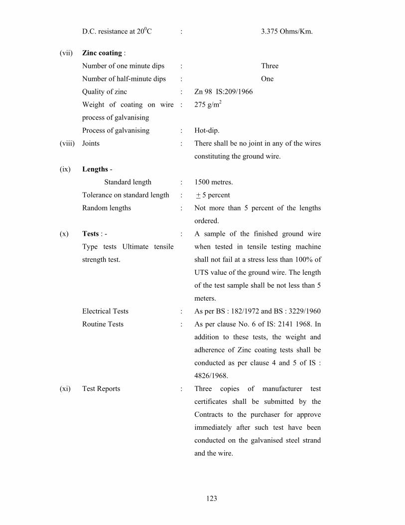
123
D.C. resistance at 200C : 3.375 Ohms/Km.
(vii) Zinc coating :
Number of one minute dips : Three
Number of half-minute dips : One
Quality of zinc : Zn 98 IS:209/1966
Weight of coating on wire
process of galvanising
: 275 g/m2
Process of galvanising : Hot-dip.
(viii) Joints : There shall be no joint in any of the wires
constituting the ground wire.
(ix) Lengths -
Standard length : 1500 metres.
Tolerance on standard length : + 5 percent
Random lengths : Not more than 5 percent of the lengths
ordered.
(x) Tests : -
Type tests Ultimate tensile
strength test.
: A sample of the finished ground wire
when tested in tensile testing machine
shall not fail at a stress less than 100% of
UTS value of the ground wire. The length
of the test sample shall be not less than 5
meters.
Electrical Tests : As per BS : 182/1972 and BS : 3229/1960
Routine Tests : As per clause No. 6 of IS: 2141 1968. In
addition to these tests, the weight and
adherence of Zinc coating tests shall be
conducted as per clause 4 and 5 of IS :
4826/1968.
(xi) Test Reports : Three copies of manufacturer test
certificates shall be submitted by the
Contracts to the purchaser for approve
immediately after such test have been
conducted on the galvanised steel strand
and the wire.
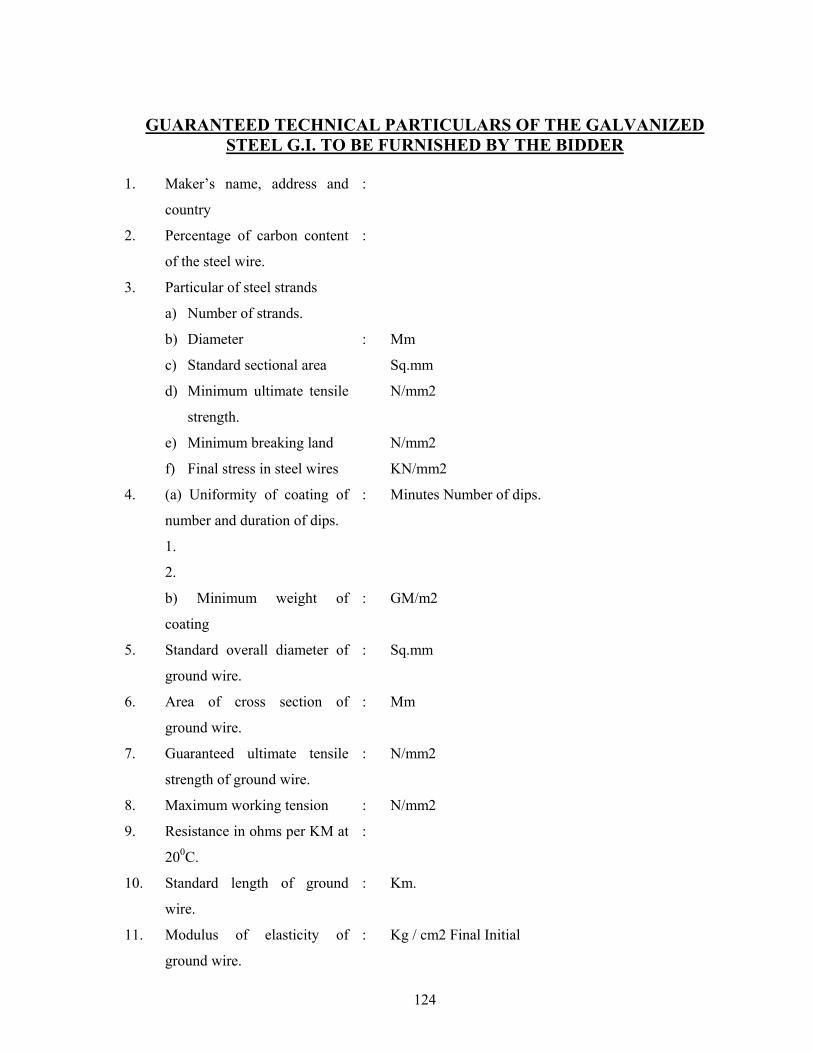
124
GUARANTEED TECHNICAL PARTICULARS OF THE GALVANIZED STEEL G.I. TO BE FURNISHED BY THE BIDDER
1. Maker’s name, address and
country
:
2. Percentage of carbon content
of the steel wire.
:
3. Particular of steel strands
a) Number of strands.
b) Diameter
c) Standard sectional area
d) Minimum ultimate tensile
strength.
e) Minimum breaking land
f) Final stress in steel wires
:
Mm
Sq.mm
N/mm2
N/mm2
KN/mm2
4. (a) Uniformity of coating of
number and duration of dips.
: Minutes Number of dips.
1.
2.
b) Minimum weight of
coating
: GM/m2
5. Standard overall diameter of
ground wire.
: Sq.mm
6. Area of cross section of
ground wire.
: Mm
7. Guaranteed ultimate tensile
strength of ground wire.
: N/mm2
8. Maximum working tension : N/mm2
9. Resistance in ohms per KM at
200C.
:
10. Standard length of ground
wire.
: Km.
11. Modulus of elasticity of
ground wire.
: Kg / cm2 Final Initial
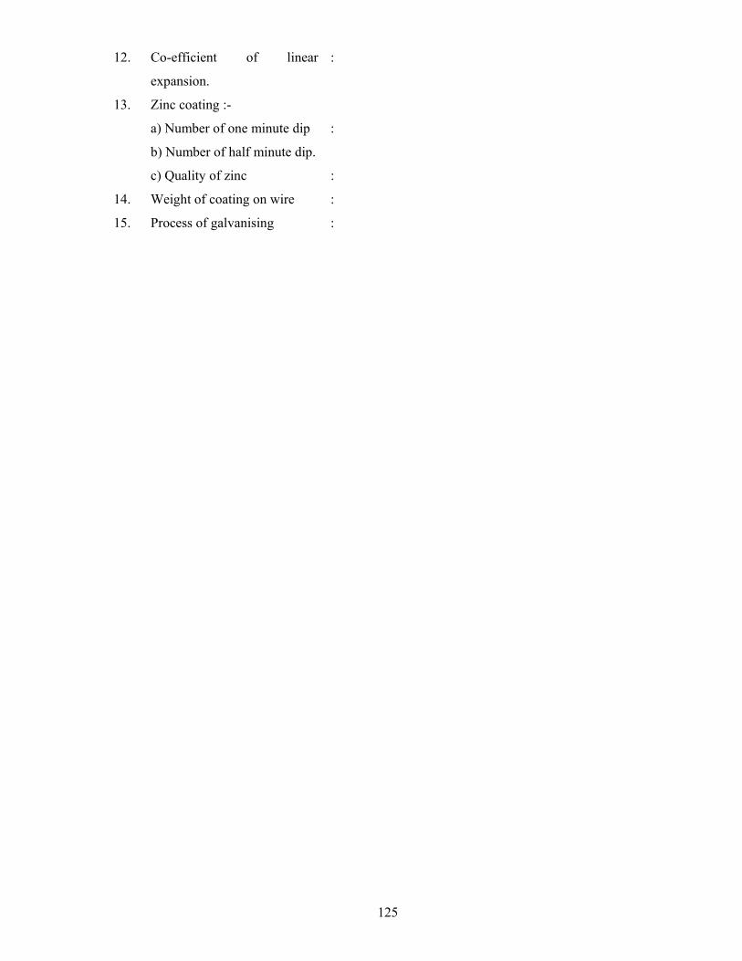
125
12. Co-efficient of linear
expansion.
:
13. Zinc coating :-
a) Number of one minute dip :
b) Number of half minute dip.
c) Quality of zinc :
14. Weight of coating on wire :
15. Process of galvanising :

126
SECTION-XIII
INSULATORS
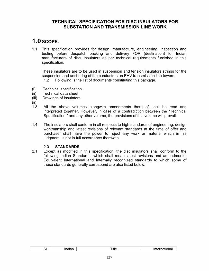
127
TECHNICAL SPECIFICATION FOR DISC INSULATORS FOR
SUBSTATION AND TRANSMISSION LINE WORK
1.0 SCOPE. 1.1 This specification provides for design, manufacture, engineering, inspection and
testing before despatch packing and delivery FOR (destination) for Indian manufacturers of disc. Insulators as per technical requirements furnished in this specification.
These insulators are to be used in suspension and tension insulators strings for the suspension and anchoring of the conductors on EHV transmission line towers. 1.2 Following is the list of documents constituting this package.
(i) Technical specification. (ii) Technical data sheet. (iii) Drawings of insulators (ii) 1.3 All the above volumes alongwith amendments there of shall be read and
interpreted together. However, in case of a contradiction between the “Technical Specification ” and any other volume, the provisions of this volume will prevail.
1.4 The insulators shall conform in all respects to high standards of engineering, design workmanship and latest revisions of relevant standards at the time of offer and purchaser shall have the power to reject any work or material which in his judgment, is not in full accordance therewith. 2.0 STANDARDS:
2.1 Except as modified in this specification, the disc insulators shall conform to the following Indian Standards, which shall mean latest revisions and amendments. Equivalent International and Internally recognized standards to which some of these standards generally correspond are also listed below. Sl. Indian Title. International
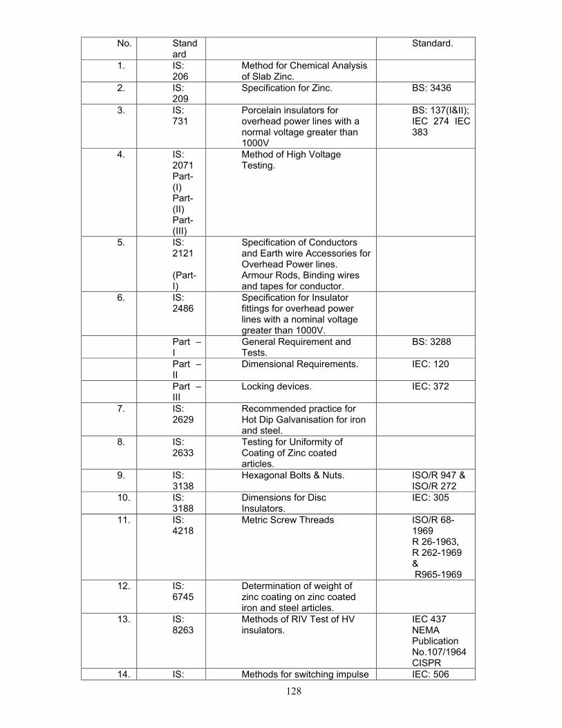
128
No. Standard
Standard.
1. IS: 206
Method for Chemical Analysis of Slab Zinc.
2. IS: 209
Specification for Zinc. BS: 3436
3. IS: 731
Porcelain insulators for overhead power lines with a normal voltage greater than 1000V
BS: 137(I&II); IEC 274 IEC 383
4. IS: 2071 Part-(I) Part-(II) Part-(III)
Method of High Voltage Testing.
5. IS: 2121 (Part-I)
Specification of Conductors and Earth wire Accessories for Overhead Power lines. Armour Rods, Binding wires and tapes for conductor.
6. IS: 2486
Specification for Insulator fittings for overhead power lines with a nominal voltage greater than 1000V.
Part – I
General Requirement and Tests.
BS: 3288
Part – II
Dimensional Requirements. IEC: 120
Part – III
Locking devices. IEC: 372
7. IS: 2629
Recommended practice for Hot Dip Galvanisation for iron and steel.
8. IS: 2633
Testing for Uniformity of Coating of Zinc coated articles.
9. IS: 3138
Hexagonal Bolts & Nuts. ISO/R 947 & ISO/R 272
10. IS: 3188
Dimensions for Disc Insulators.
IEC: 305
11. IS: 4218
Metric Screw Threads ISO/R 68-1969 R 26-1963, R 262-1969 & R965-1969
12. IS: 6745
Determination of weight of zinc coating on zinc coated iron and steel articles.
13. IS: 8263
Methods of RIV Test of HV insulators.
IEC 437 NEMA Publication No.107/1964 CISPR
14. IS: Methods for switching impulse IEC: 506
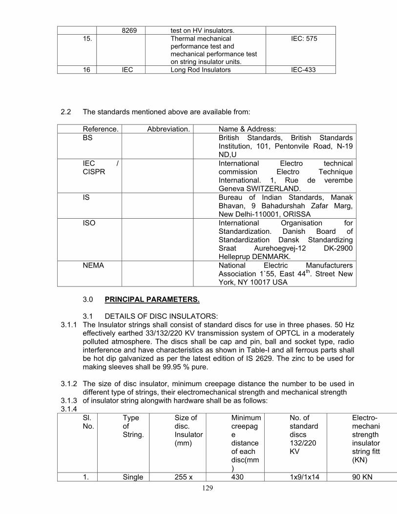
129
8269 test on HV insulators. 15. Thermal mechanical
performance test and mechanical performance test on string insulator units.
IEC: 575
16 IEC Long Rod Insulators IEC-433
2.2 The standards mentioned above are available from: Reference. Abbreviation. Name & Address: BS British Standards, British Standards
Institution, 101, Pentonvile Road, N-19 ND,U
IEC / CISPR
International Electro technical commission Electro Technique International. 1, Rue de verembe Geneva SWITZERLAND.
IS Bureau of Indian Standards, Manak Bhavan, 9 Bahadurshah Zafar Marg, New Delhi-110001, ORISSA
ISO International Organisation for Standardization. Danish Board of Standardization Dansk Standardizing Sraat Aurehoegvej-12 DK-2900 Helleprup DENMARK.
NEMA National Electric Manufacturers Association 1`55, East 44th. Street New York, NY 10017 USA
3.0 PRINCIPAL PARAMETERS. 3.1 DETAILS OF DISC INSULATORS:
3.1.1 The Insulator strings shall consist of standard discs for use in three phases. 50 Hz effectively earthed 33/132/220 KV transmission system of OPTCL in a moderately polluted atmosphere. The discs shall be cap and pin, ball and socket type, radio interference and have characteristics as shown in Table-I and all ferrous parts shall be hot dip galvanized as per the latest edition of IS 2629. The zinc to be used for making sleeves shall be 99.95 % pure.
3.1.2 The size of disc insulator, minimum creepage distance the number to be used in different type of strings, their electromechanical strength and mechanical strength
3.1.3 of insulator string alongwith hardware shall be as follows: 3.1.4
Sl. No.
Type of String.
Size of disc. Insulator (mm)
Minimum creepage distance of each disc(mm)
No. of standard discs 132/220 KV
Electro-mechanicstrength insulator string fitti(KN)
1. Single 255 x 430 1x9/1x14 90 KN
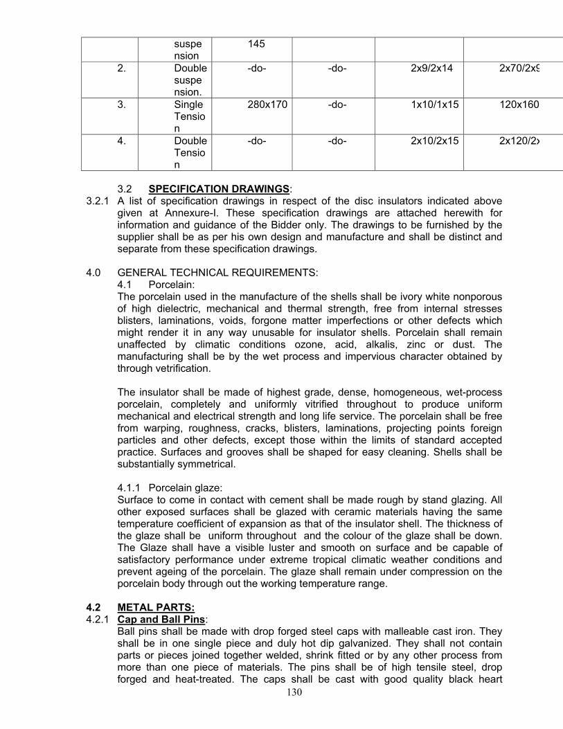
130
suspension
145
2. Double suspension.
-do- -do- 2x9/2x14 2x70/2x9
3. Single Tension
280x170 -do- 1x10/1x15 120x160
4. Double Tension
-do- -do- 2x10/2x15 2x120/2x
3.2 SPECIFICATION DRAWINGS:
3.2.1 A list of specification drawings in respect of the disc insulators indicated above given at Annexure-I. These specification drawings are attached herewith for information and guidance of the Bidder only. The drawings to be furnished by the supplier shall be as per his own design and manufacture and shall be distinct and separate from these specification drawings.
4.0 GENERAL TECHNICAL REQUIREMENTS: 4.1 Porcelain: The porcelain used in the manufacture of the shells shall be ivory white nonporous of high dielectric, mechanical and thermal strength, free from internal stresses blisters, laminations, voids, forgone matter imperfections or other defects which might render it in any way unusable for insulator shells. Porcelain shall remain unaffected by climatic conditions ozone, acid, alkalis, zinc or dust. The manufacturing shall be by the wet process and impervious character obtained by through vetrification. The insulator shall be made of highest grade, dense, homogeneous, wet-process porcelain, completely and uniformly vitrified throughout to produce uniform mechanical and electrical strength and long life service. The porcelain shall be free from warping, roughness, cracks, blisters, laminations, projecting points foreign particles and other defects, except those within the limits of standard accepted practice. Surfaces and grooves shall be shaped for easy cleaning. Shells shall be substantially symmetrical. 4.1.1 Porcelain glaze: Surface to come in contact with cement shall be made rough by stand glazing. All other exposed surfaces shall be glazed with ceramic materials having the same temperature coefficient of expansion as that of the insulator shell. The thickness of the glaze shall be uniform throughout and the colour of the glaze shall be down. The Glaze shall have a visible luster and smooth on surface and be capable of satisfactory performance under extreme tropical climatic weather conditions and prevent ageing of the porcelain. The glaze shall remain under compression on the porcelain body through out the working temperature range.
4.2 METAL PARTS: 4.2.1 Cap and Ball Pins:
Ball pins shall be made with drop forged steel caps with malleable cast iron. They shall be in one single piece and duly hot dip galvanized. They shall not contain parts or pieces joined together welded, shrink fitted or by any other process from more than one piece of materials. The pins shall be of high tensile steel, drop forged and heat-treated. The caps shall be cast with good quality black heart
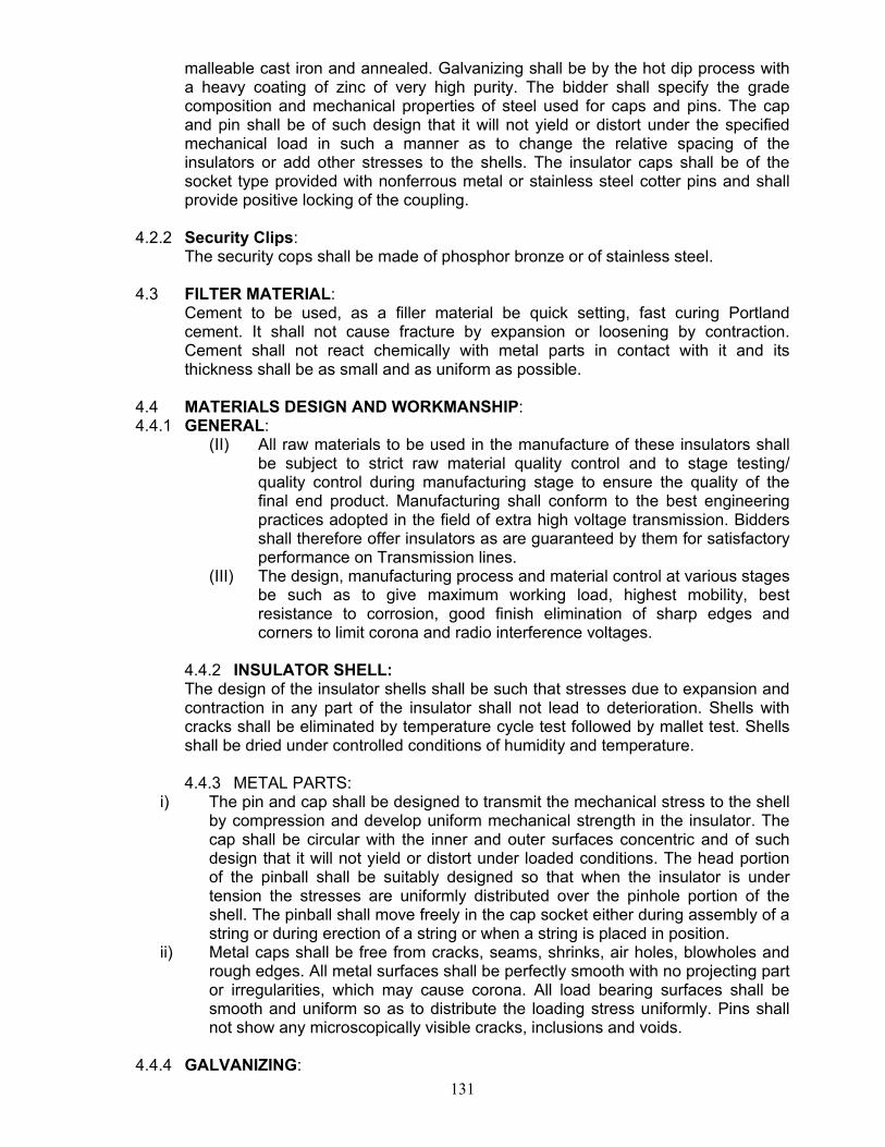
131
malleable cast iron and annealed. Galvanizing shall be by the hot dip process with a heavy coating of zinc of very high purity. The bidder shall specify the grade composition and mechanical properties of steel used for caps and pins. The cap and pin shall be of such design that it will not yield or distort under the specified mechanical load in such a manner as to change the relative spacing of the insulators or add other stresses to the shells. The insulator caps shall be of the socket type provided with nonferrous metal or stainless steel cotter pins and shall provide positive locking of the coupling.
4.2.2 Security Clips: The security cops shall be made of phosphor bronze or of stainless steel.
4.3 FILTER MATERIAL: Cement to be used, as a filler material be quick setting, fast curing Portland cement. It shall not cause fracture by expansion or loosening by contraction. Cement shall not react chemically with metal parts in contact with it and its thickness shall be as small and as uniform as possible.
4.4 MATERIALS DESIGN AND WORKMANSHIP: 4.4.1 GENERAL:
(II) All raw materials to be used in the manufacture of these insulators shall be subject to strict raw material quality control and to stage testing/ quality control during manufacturing stage to ensure the quality of the final end product. Manufacturing shall conform to the best engineering practices adopted in the field of extra high voltage transmission. Bidders shall therefore offer insulators as are guaranteed by them for satisfactory performance on Transmission lines.
(III) The design, manufacturing process and material control at various stages be such as to give maximum working load, highest mobility, best resistance to corrosion, good finish elimination of sharp edges and corners to limit corona and radio interference voltages.
4.4.2 INSULATOR SHELL: The design of the insulator shells shall be such that stresses due to expansion and contraction in any part of the insulator shall not lead to deterioration. Shells with cracks shall be eliminated by temperature cycle test followed by mallet test. Shells shall be dried under controlled conditions of humidity and temperature. 4.4.3 METAL PARTS:
i) The pin and cap shall be designed to transmit the mechanical stress to the shell by compression and develop uniform mechanical strength in the insulator. The cap shall be circular with the inner and outer surfaces concentric and of such design that it will not yield or distort under loaded conditions. The head portion of the pinball shall be suitably designed so that when the insulator is under tension the stresses are uniformly distributed over the pinhole portion of the shell. The pinball shall move freely in the cap socket either during assembly of a string or during erection of a string or when a string is placed in position.
ii) Metal caps shall be free from cracks, seams, shrinks, air holes, blowholes and rough edges. All metal surfaces shall be perfectly smooth with no projecting part or irregularities, which may cause corona. All load bearing surfaces shall be smooth and uniform so as to distribute the loading stress uniformly. Pins shall not show any microscopically visible cracks, inclusions and voids.
4.4.4 GALVANIZING:
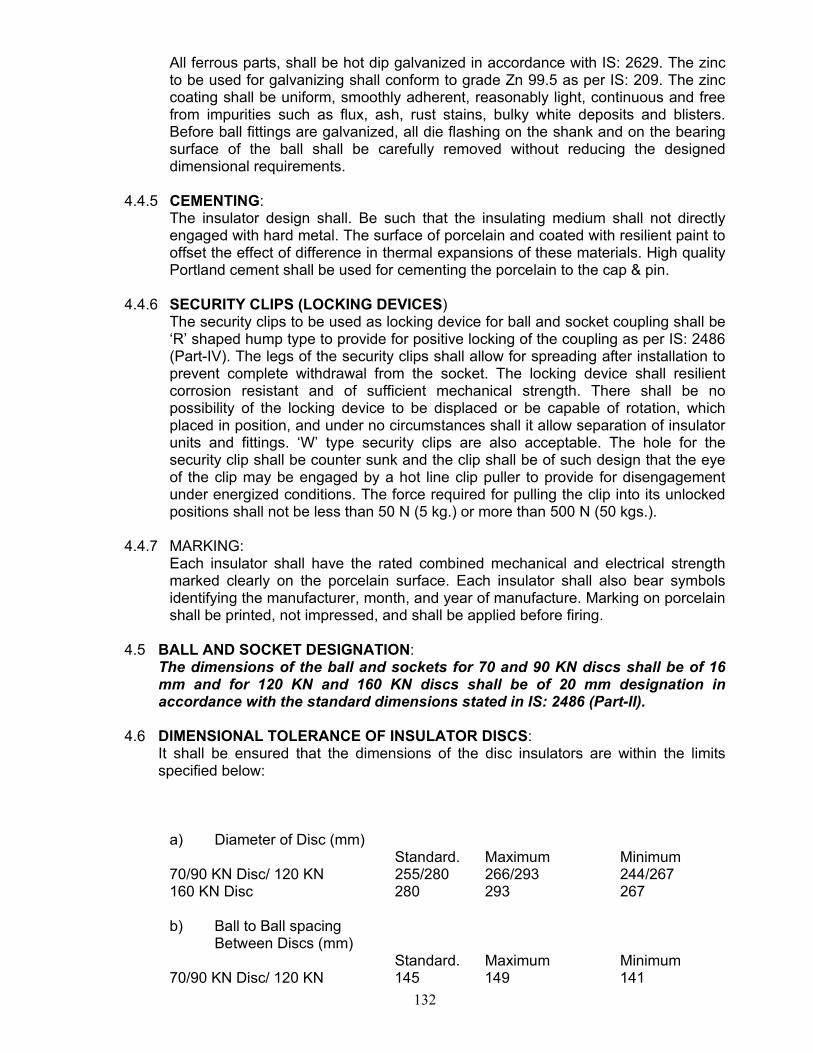
132
All ferrous parts, shall be hot dip galvanized in accordance with IS: 2629. The zinc to be used for galvanizing shall conform to grade Zn 99.5 as per IS: 209. The zinc coating shall be uniform, smoothly adherent, reasonably light, continuous and free from impurities such as flux, ash, rust stains, bulky white deposits and blisters. Before ball fittings are galvanized, all die flashing on the shank and on the bearing surface of the ball shall be carefully removed without reducing the designed dimensional requirements.
4.4.5 CEMENTING: The insulator design shall. Be such that the insulating medium shall not directly engaged with hard metal. The surface of porcelain and coated with resilient paint to offset the effect of difference in thermal expansions of these materials. High quality Portland cement shall be used for cementing the porcelain to the cap & pin.
4.4.6 SECURITY CLIPS (LOCKING DEVICES) The security clips to be used as locking device for ball and socket coupling shall be ‘R’ shaped hump type to provide for positive locking of the coupling as per IS: 2486 (Part-IV). The legs of the security clips shall allow for spreading after installation to prevent complete withdrawal from the socket. The locking device shall resilient corrosion resistant and of sufficient mechanical strength. There shall be no possibility of the locking device to be displaced or be capable of rotation, which placed in position, and under no circumstances shall it allow separation of insulator units and fittings. ‘W’ type security clips are also acceptable. The hole for the security clip shall be counter sunk and the clip shall be of such design that the eye of the clip may be engaged by a hot line clip puller to provide for disengagement under energized conditions. The force required for pulling the clip into its unlocked positions shall not be less than 50 N (5 kg.) or more than 500 N (50 kgs.).
4.4.7 MARKING: Each insulator shall have the rated combined mechanical and electrical strength marked clearly on the porcelain surface. Each insulator shall also bear symbols identifying the manufacturer, month, and year of manufacture. Marking on porcelain shall be printed, not impressed, and shall be applied before firing.
4.5 BALL AND SOCKET DESIGNATION: The dimensions of the ball and sockets for 70 and 90 KN discs shall be of 16 mm and for 120 KN and 160 KN discs shall be of 20 mm designation in accordance with the standard dimensions stated in IS: 2486 (Part-II).
4.6 DIMENSIONAL TOLERANCE OF INSULATOR DISCS:
It shall be ensured that the dimensions of the disc insulators are within the limits specified below:
a) Diameter of Disc (mm) Standard. Maximum Minimum 70/90 KN Disc/ 120 KN 255/280 266/293 244/267 160 KN Disc 280 293 267 b) Ball to Ball spacing Between Discs (mm) Standard. Maximum Minimum 70/90 KN Disc/ 120 KN 145 149 141
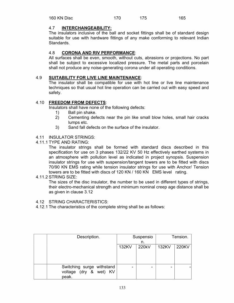
133
160 KN Disc 170 175 165 4.7 INTERCHANGEABILITY: The insulators inclusive of the ball and socket fittings shall be of standard design suitable for use with hardware fittings of any make conforming to relevant Indian Standards. 4.8 CORONA AND RIV PERFORMANCE: All surfaces shall be even, smooth, without cuts, abrasions or projections. No part shall be subject to excessive localized pressure. The metal parts and porcelain shall not produce any noise-generating corona under all operating conditions.
4.9 SUITABILITY FOR LIVE LINE MAINTENANCE: The insulator shall be compatible for use with hot line or live line maintenance techniques so that usual hot line operation can be carried out with easy speed and safety.
4.10 FREEDOM FROM DEFECTS: Insulators shall have none of the following defects:
1) Ball pin shake. 2) Cementing defects near the pin like small blow holes, small hair cracks
lumps etc. 3) Sand fall defects on the surface of the insulator.
4.11 INSULATOR STRINGS: 4.11.1 TYPE AND RATING:
The insulator strings shall be formed with standard discs described in this specification for use on 3 phases 132/22 KV 50 Hz effectively earthed systems in an atmosphere with pollution level as indicated in project synopsis. Suspension insulator strings for use with suspension/tangent towers are to be fitted with discs 70/90 KN EMS rating while tension insulator strings for use with Anchor/ Tension towers are to be fitted with discs of 120 KN / 160 KN EMS level rating.
4.11.2 STRING SIZE: The sizes of the disc insulator, the number to be used in different types of strings, their electro-mechanical strength and minimum nominal creep age distance shall be as given in clause 3.12
4.12 STRING CHARACTERISTICS: 4.12.1 The characteristics of the complete string shall be as follows:
Suspension.
Tension. Description.
132KV 220kV 132KV 220KV
Switching surge withstand voltage (dry & wet) KV peak.
- - - -
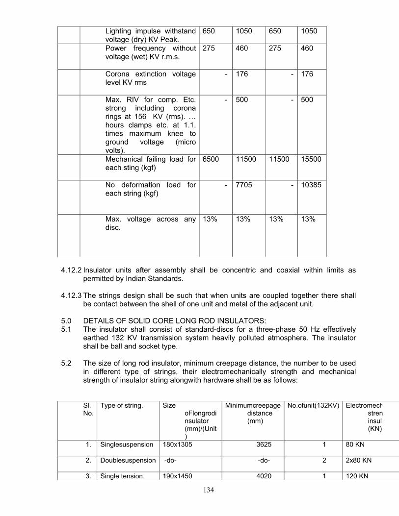
134
Lighting impulse withstand voltage (dry) KV Peak.
650 1050 650 1050
Power frequency without voltage (wet) KV r.m.s.
275 460 275 460
Corona extinction voltage level KV rms
- 176 - 176
Max. RIV for comp. Etc. strong including corona rings at 156 KV (rms). … hours clamps etc. at 1.1. times maximum knee to ground voltage (micro volts).
- 500 - 500
Mechanical failing load for each sting (kgf)
6500 11500 11500 15500
No deformation load for each string (kgf)
- 7705 - 10385
Max. voltage across any disc.
13% 13% 13% 13%
4.12.2 Insulator units after assembly shall be concentric and coaxial within limits as
permitted by Indian Standards.
4.12.3 The strings design shall be such that when units are coupled together there shall be contact between the shell of one unit and metal of the adjacent unit.
5.0 DETAILS OF SOLID CORE LONG ROD INSULATORS: 5.1 The insulator shall consist of standard-discs for a three-phase 50 Hz effectively
earthed 132 KV transmission system heavily polluted atmosphere. The insulator shall be ball and socket type.
5.2 The size of long rod insulator, minimum creepage distance, the number to be used in different type of strings, their electromechanically strength and mechanical strength of insulator string alongwith hardware shall be as follows:
Sl. No.
Type of string. Size oFlongrodinsulator (mm)/(Unit)
Minimumcreepage distance (mm)
No.ofunit(132KV) Electromechstreninsula(KN)
1.
Singlesuspension 180x1305 3625 1 80 KN
2.
Doublesuspension -do- -do- 2 2x80 KN
3. Single tension. 190x1450 4020 1 120 KN
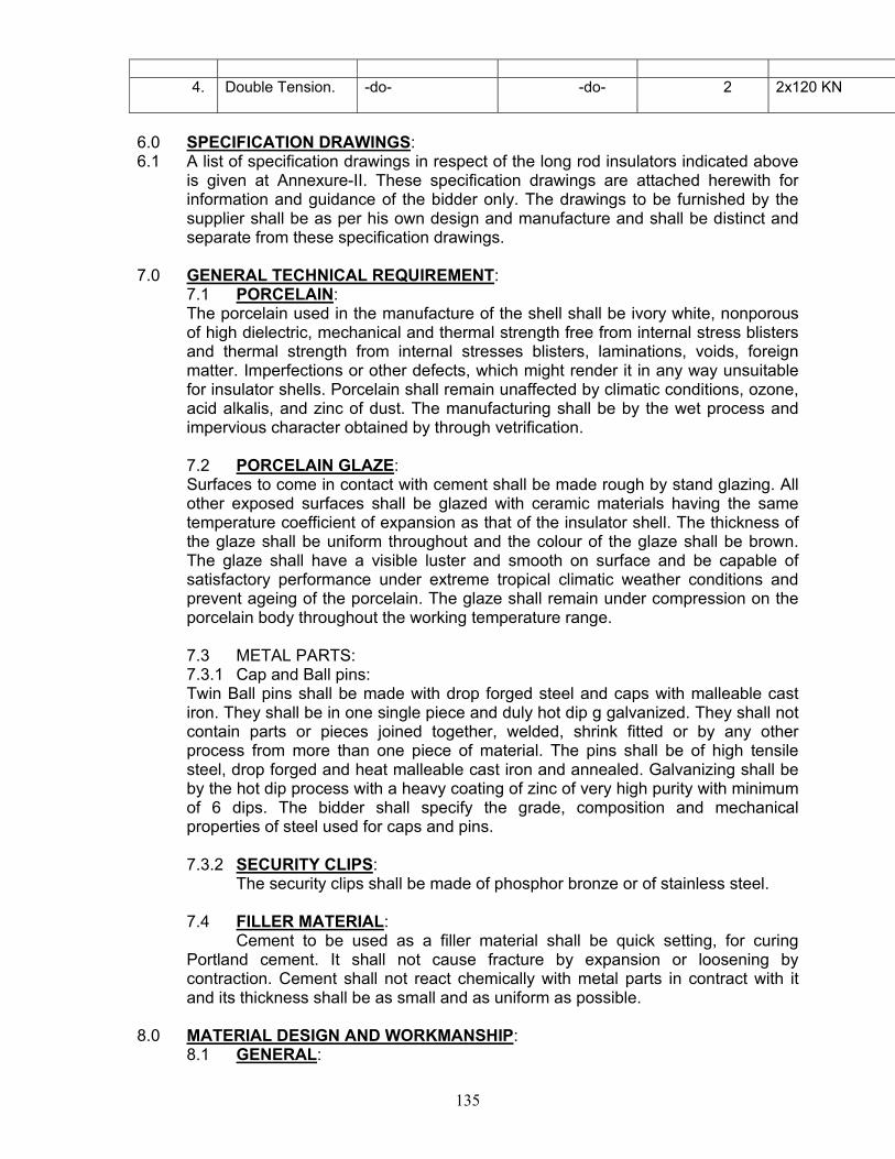
135
4.
Double Tension. -do- -do- 2 2x120 KN
6.0 SPECIFICATION DRAWINGS: 6.1 A list of specification drawings in respect of the long rod insulators indicated above
is given at Annexure-II. These specification drawings are attached herewith for information and guidance of the bidder only. The drawings to be furnished by the supplier shall be as per his own design and manufacture and shall be distinct and separate from these specification drawings.
7.0 GENERAL TECHNICAL REQUIREMENT: 7.1 PORCELAIN: The porcelain used in the manufacture of the shell shall be ivory white, nonporous of high dielectric, mechanical and thermal strength free from internal stress blisters and thermal strength from internal stresses blisters, laminations, voids, foreign matter. Imperfections or other defects, which might render it in any way unsuitable for insulator shells. Porcelain shall remain unaffected by climatic conditions, ozone, acid alkalis, and zinc of dust. The manufacturing shall be by the wet process and impervious character obtained by through vetrification. 7.2 PORCELAIN GLAZE: Surfaces to come in contact with cement shall be made rough by stand glazing. All other exposed surfaces shall be glazed with ceramic materials having the same temperature coefficient of expansion as that of the insulator shell. The thickness of the glaze shall be uniform throughout and the colour of the glaze shall be brown. The glaze shall have a visible luster and smooth on surface and be capable of satisfactory performance under extreme tropical climatic weather conditions and prevent ageing of the porcelain. The glaze shall remain under compression on the porcelain body throughout the working temperature range. 7.3 METAL PARTS: 7.3.1 Cap and Ball pins: Twin Ball pins shall be made with drop forged steel and caps with malleable cast iron. They shall be in one single piece and duly hot dip g galvanized. They shall not contain parts or pieces joined together, welded, shrink fitted or by any other process from more than one piece of material. The pins shall be of high tensile steel, drop forged and heat malleable cast iron and annealed. Galvanizing shall be by the hot dip process with a heavy coating of zinc of very high purity with minimum of 6 dips. The bidder shall specify the grade, composition and mechanical properties of steel used for caps and pins. 7.3.2 SECURITY CLIPS: The security clips shall be made of phosphor bronze or of stainless steel. 7.4 FILLER MATERIAL: Cement to be used as a filler material shall be quick setting, for curing Portland cement. It shall not cause fracture by expansion or loosening by contraction. Cement shall not react chemically with metal parts in contract with it and its thickness shall be as small and as uniform as possible.
8.0 MATERIAL DESIGN AND WORKMANSHIP: 8.1 GENERAL:
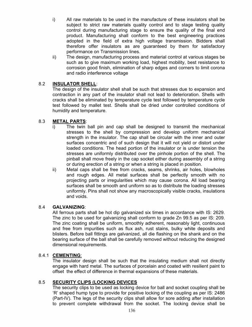
136
i) All raw materials to be used in the manufacture of these insulators shall be subject to strict raw materials quality control and to stage testing quality control during manufacturing stage to ensure the quality of the final end product. Manufacturing shall conform to the best engineering practices adopted in the field of extra high voltage transmission. Bidders shall therefore offer insulators as are guaranteed by them for satisfactory performance on Transmission lines.
ii) The design, manufacturing process and material control at various stages be such as to give maximum working load, highest mobility, best resistance to corrosion good finish, elimination of sharp edges and corners to limit corona and radio interference voltage
8.2 INSULATOR SHELL:
The design of the insulator shell shall be such that stresses due to expansion and contraction in any part of the insulator shall not lead to deterioration. Shells with cracks shall be eliminated by temperature cycle test followed by temperature cycle test followed by mallet test. Shells shall be dried under controlled conditions of humidity and temperature.
8.3 METAL PARTS: i) The twin ball pin and cap shall be designed to transmit the mechanical
stresses to the shell by compression and develop uniform mechanical strength in the insulator. The cap shall be circular with the inner and outer surfaces concentric and of such design that it will not yield or distort under loaded conditions. The head portion of the insulator or is under tension the stresses are uniformly distributed over the pinhole portion of the shell. The pinball shall move freely in the cap socket either during assembly of a string or during erection of a string or when a string is placed in position.
ii) Metal caps shall be free from cracks, seams, shrinks, air holes, blowholes and rough edges. All metal surfaces shall be perfectly smooth with no projecting parts or irregularities which may cause corona. All load bearing surfaces shall be smooth and uniform so as to distribute the loading stresses uniformly. Pins shall not show any macroscopically visible cracks, insulations and voids.
8.4 GALVANIZING:
All ferrous parts shall be hot dip galvanized six times in accordance with IS: 2629. The zinc to be used for galvanizing shall conform to grade Zn 99.5 as per IS: 209. The zinc coating shall be uniform, smoothly adherent, reasonably light, continuous and free from impurities such as flux ash, rust stains, bulky white deposits and blisters. Before ball fittings are galvanized, all die flashing on the shank and on the bearing surface of the ball shall be carefully removed without reducing the designed dimensional requirements.
8.4.1 CEMENTING: The insulator design shall be such that the insulating medium shall not directly engage with hard metal. The surfaces of porcelain and coated with resilient paint to offset the effect of difference in thermal expansions of these materials.
8.5 SECURITY CLIPS (LOCKING DEVICES The security clips to be used as locking device for ball and socket coupling shall be ‘R’ shaped hump type to provide for positive locking of the coupling as per IS: 2486 (Part-IV). The legs of the security clips shall allow for sore adding after installation to prevent complete withdrawal from the socket. The locking device shall be
137
resilient corrosion resistant and of sufficient mechanical strength. There shall be no possibility of the locking device to be displaced or be capable of rotation when placed in position and under no circumstances shall it allow separation of insulator units and fitting ‘W’ type security clips are also acceptable. The hole for the security clip shall be countersunk and the clip shall be of such design that the eye of the clip may be engaged by a hot line clip puller to provide for disengagement under energized conditions. The force required for pulling the clip into its unlocked position shall not be less than 50 N (5 Kgs.) or more than 500N (50 Kgs.)
8.6 BALL AND SOCKET DESIGNATION: The dimensions of the balls and sockets for 80 KN long rod insulators shall be of 16mm and for 120 KN shall be of 20mm designation in accordance with the standard dimensions stated in IS: 2486 (Part-III).
8.7 DIMENSIONAL TOLERANCE OF INSULATORS DISCS It shall be ensured that the dimensions of the long rod insulators are within the limits as per relevant IEC/ISS.
9.0 TESTS (FOR DISC INSULATORS) : 9,1 The following tests shall be carried out on the insulator string and disc insulators.
9.2 TYPE TEST:
This shall mean those tests, which are to be carried out to prove the design, process of manufacture and general conformity of the material and product with the intents of this specification. These tests shall be conducted on a representative number of samples prior to commencement of commercial production. The Bidder shall indicate his schedule for carrying out these tests.
9.3 ACCEPTANCE: This shall mean these tests, which are to be carried out on samples taken from each lot offered for pre-despatch inspection for the purpose of acceptance of the lot.
9.4 ROUTINE TESTS: This shall mean those tests, which are to be carried out on each insulator to check the requirements, which are likely to vary during production.
9.5 TESTS DURING MANUFACTURE: Stage tests during manufacture shall mean those tests, which are to be carried out during the process of manufacture to ensure quality control such that the end product is of the designed quality conforming to the intent of this specification.
9.6 TEST VALUE: For all type and acceptance tests the acceptance values shall be the value guaranteed by the bidder in the guaranteed technical particulars of the acceptance value specified in this specification of the relevant standard whichever is more stringent for that particular test.
9.7 TEST PROCEDURE AND SAMPLING NORMS: The norms and procedure of sampling for the above tests shall be as per the relevant Indian Standard or the Internationally accepted standards. This will be discussed and mutually agreed to between the supplier and purchaser before placement of order. The standards and normal according to which these tests are to be carried out are listed against each test. Where a particular test is a specific
138
requirement of this specification, the norms land procedure for the same shall be as specified in Annexure-IV attached hereto as mutually agreed to between the supplier and the purchaser in the quality assurance programme.
9.8 TYPE TESTS: The following type test shall be conducted on a suitable number of individual unit components, materials or complete strings.
9.8.1 On the complete insulator string with hardware fittings. a) Power frequency voltage withstand test with
corona control rings and under wet condition. : BS:137(Part-I)
b) Switching surge voltage withstand test under wet condition (400 only)
:
c) Impulse voltage withstand test under dry condition.
: IEC: 383
d) Impulse voltage flashover test under dry condition.
:
e) Voltage distribution test. : f) Corona & RIV test under dry condition. : As per
this specification.
g) Mechanical strength test. : As per this specification.
h) Vibration. : 9.8.2 On Insulators: a) Verification of dimensions. : IS: 731 b) Thermal mechanical performance test: : IEC:575 c) Power frequency voltage withstand and
flashover (I) dry (ii) wet.
: BS: 173
d) Impulse voltage withstand flashover test (dry) : IEC: 383 e) Visible discharge test (dry) : IS:731 f) RIV test (dry) : IS:8263 9.8.3 All the type tests given under clause No.6.8.1
above shall be conducted on single suspension and Double Tension insulator string alongwith hardware fittings.
9.9 ACCEPTANCE TESTS: 9.9.1 For insulator: a) Visual examination : IS:731 b) Verification of dimensions. : IS:731 c) Temperature cycle test. : IS:731 d) Galvanizing test. : IS:731 e) Mechanical performance test. : IEC:575 f) Test on locking device for ball and socket
coupling. : IEC:372
g) Eccentricity test. : As per
139
this specification.
h) Electro-mechanical strength test. : i) Puncture test. : IS:731 j) Porosity test. : IS:731 9.10 ROUTINE TESTS: 9.10.1 For insulators: a) Visual inspection. : IS:731 b) Mechanical routine test. : c) Electrical routine test. : IEC:383 9.11 TEST DURING MANUFACTURE: On all components as applicable. a) Chemical analysis of zinc used for
galvanizing. :
b) Chemical analysis, mechanical and metallographic test and magnetic particle inspection for malleable castings.
:
c) Chemical analysis, hardness test and magnetic particle inspection for forgings.
: As per this specification.
d) Hydraulic Internal Pressure tests on shell. : e) Crack detection test for metal parts. :
9.12 ADDITIONAL TEST: The purchaser reserves the right for carrying out any other tests of a reasonable nature at the works of the supplier/ laboratory or at any other recognized laboratory/ research institute in addition to the above mentioned type, acceptance and routine tests at the cost of the purchaser to satisfy that the material complies with the intent of this specification.
9.13 CO-ORDINATION FOR TESTING: For insulator strings, the supplier shall arrange to conduct testing of their disc insulators with the hardware fittings to be supplied to the purchaser by other suppliers. The supplier is also required to guarantee overall satisfactory performance of the disc insulator with the hardware fittings. NOTE: In respect of electrical tests on a complete string consisting of insulators and hardware guarantee of values of responsibility of testing shall be with hardware manufacturer of RIV corona and voltage distribution test and with insulator manufacturer for all other tests.
9.14 TEST CHARGES AND TEST SCHEDULE: 9.14.1 TYPE TEST:
The insulator offered shall be fully type tested as per this specification. In case the equipment of the type and design offered, has already been type tested in an independent test laboratory. The bidder shall furnish four sets of type test reports alongwith the offer. These tests must not have been conducted earlier than five years. The purchaser reserves the right to demand repetition of some or all type tests in the presence of purchasers’ carrying representative. For this purpose the
140
bidder may quote unit rates for carrying out each type test. These prices shall be taken into consideration for bid evaluation. For any change in the design/type already type tested and the design/type offered against this specification, purchaser reserves the right to demand repetition of tests without any extra cost.
9.14.2 ACCEPTANCE AND ROUTINE TEST: All acceptance and routine tests as stipulated herein shall be carried out by the supplier in the presence of purchaser’s representative.
9.14.3 Immediately after finalisation of the programme of type/ acceptance/ routine testing, the supplier shall give sufficient advance intimation to the purchaser to enable him to depute his representative for witnessing the tests.
9.14.4 For type tests involving tests on a complete insulator string with hardware fittings, the purchaser will advice the supplier of the hardware fittings to provide the necessary fittings to the place of the test.
9.14.5 In case of failure of the complete string in any type tests, the supplier whose product has failed in the tests, shall get the tests repeated at his cost. In case of any dispute, assessment of the purchaser as to the items that has caused the failure in any of the type tests shall be final and binding. 10. INSPECTION:
10.1 i. Purchaser and its representative shall at all times be entitled to have access to the works and to all places of manufacturer where insulators are manufactured and the supplier shall afford all facilities to them for unrestricted inspection of the works, inspection of materials, inspection of manufacturing process of insulators and for conducting necessary tests as specified herein.
ii. The supplier shall keep the purchaser informed in advance of the time of starting and of progress of manufacture of insulators in its various stages so that arrangements could be made for inspection.
iii. No material shall be dispatched from its point of manufacture unless the materials has been satisfactorily inspected and tested.
iv. The acceptance of any quantity of insulators shall in no way relieve the
supplier of his responsibility for meeting all the requirement of this specification and shall not prevent subsequent rejection, if such insulators are later found to be defective.
10.2 IDENTIFICATION MARKING:
10.2.1 Each unit of insulator shall be legibly and indelibly marked with the trade mark of
the supplier, the year of manufacture, the guaranteed combined mechanical and electrical strength in kilo-newtons abbreviated by ‘KN’ to facilitate easy identification and proper use.
10.2.2 The marking shall be on porcelain for porcelain insulators. The marking shall be
printed and not impressed and the same shall be applied before firing. 11. QUALITY ASSURANCE PLAN:
11.1 The bidder hereunder shall invariably furnish following information alongwith his offer, failing which the offer shall be liable for rejection.
141
i. Statement giving list of important raw materials, names of sub-suppliers for the raw materials, list of standards according to which the raw material are tested, list of tests normally carried out on raw materials in presence of bidder’s representative, copies of test certificates.
ii. Informations and copies of test certificates as in (i) above in respect of bought out materials.
iii. List of manufacturing facilities available. iv. Level of automation achieved and lists of area where manual
processing exists. v. List of areas in manufacturing process, where stage inspections are
normally carried out in quality control and details of such tests and inspection.
vi. Special features provided in the equipment to make it maintenance free.
vii. List of testing equipping available with the bidder for final testing of equipment specified and test plant limitation, if any, vis-à-vis the type, special, acceptance and routine tests specified in the relevant standards. These limitations shall be very clearly brought out in schedule of deviations from specified test requirements.
11.2 The supplier shall within 30 days of placement of order submit the following
information to the owner. i) List of raw material and the names of sub-suppliers selected from those
furnished alongwith the offer. POST INSULATORS. Post insulator shall conform in general to IS 2544, IEC 168 and IEC 815. 3.1 constructional features Post type insulators shall consist of a porcelain part permanently secured in a metal base to be mounted on the supporting structures. They shall be capable of being mounted upright and be designed to with stand any shocks to which they may bed subjected to by the operation of the associated equipment. Only solid core insulators will be acceptable. Porcelain used shall be homogeneous, free from lamination, cavities and other flaws or imperfections that might after the mechanical or dielectric quality and shall be thoroughly vitrified, tough and impervious to moisture. Glazing of the porcelain shall be of uniform brown in colour, free from blisters, burrs and other similar defects. The insulator shall have alternate long and short sheds with aerodynamic profile. The shed profile shall also meet the requirements of IEC 815 for the specified pollution level. When operated at normal rated voltage there shall be no electric discharge between conductor and insulators which would cause corrosion or injury to conductors or insulators by the formation of substance produced by chemical action. The design of the insulators shall be such that stresses due to expansion and contraction in any part of the insulator shall not lead to deterioration. All ferrous parts shall be hot dip galvanized in accordance with the latest edition of IS 2633, and IS 4579. The zinc used for galvanizing shall be grade Zn 99.95 as per IS 209. The zinc coating shall be uniform, adherent, smooth, reasonably bright, continuous and free from imperfections such as flux ash, rust stains, bulky while
142
deposits and blisters. The metal parts shall not produce any noise generating corona under the operating conditions. Flat washer shall be circular of a diameter 2.5 times that of bolt and of suitable thickness. Where bolt heads/nuts bear upon the beveled surfaces they shall be provided with square tapered washers of suitable thickness to afford a seating square with the axis of the bolt.
Bidder shall make available data on all the essential features of design including the method of assembly of shells and metals parts, number of shells per insulator, the manner in which mechanical stresses are transmitted through shells to adjacent parts, provision for meeting expansion stresses, results of corona and thermal shock tests, recommended working strength and any special design or arrangement employed to increase life under service conditions.
143
TEST DETAILS. 1. VOLTAGE DISTRIBUTION TEST: The voltage across each insulator unit shall be measured by sphere gap method. The result obtained shall be converted into percentage and proportionate correction be applied as to give a total of 100% distribution. The voltage across any disc. Not exceed the values given in clause 4-12.1 2. CORONA EXTINCTION VOLTAGE TEST (DRY): The sample assembly when subjected to power frequency voltage shall have a corona extinction voltage of not less than the value specified at clause 4.12.1 (iv) under dry condition. There shall be no evidence of corona on any part of the sample when all possible sources of corona are photographed in a darkened room. 3. RIV TEST (DRY): Under the conditions as specified in (2) above, the insulator string along with complete hardware fittings shall have a radio interference voltage level below 500 micro volts at one MHz when subjected to 50 Hz AC voltage of 1.1 times maximum time to ground voltage under dry condition. The test procedure shall be in accordance with IS: 8263.
4. The complete insulator string along with its hardware fitting excluding arcing horn corona controlling/grading ring and suspension assembly/dead end assembly shall be subject to a load equal to 50% of the specified minimum ultimate tensile strength (UTS) which shall be increased already rate to 68% of the minimum UTS specified. The load shall be held for five minutes and then removed. After removal of the load, the string components shall not show any visual deformation and it shall be possible to disassemble them by hand,. Hand tools may be used to remove cotter pins and loosen the nuts initially. The string shall then be reassembled and loaded to 50% of UTS and the load shall be further increased at a steady rate till the specified minimum UTS and held for one minute. No fracture should occur during this period. The applied load shall then be increased until the failing loads reached and the value recorded. 5. VIBRATION TEST: The suspension string shall be tested in suspension mode, and tension string in tension mode itself in laboratory span of minimum 30 meters. In the case of suspensions string a load equal to 600 Kg. shall be applied along with the axis of the suspensions string by means of turn buckle. The insulators string along with hardware fittings and two sub conductors throughout the duration of the test vibration dampers shall not be used on the test span. Both the sub-conductors shall be vertically vibrated simultaneously at one of the resonance frequencies of the insulator string (more than 10Hz) by means of vibration inducing equipment. The amplitude of vibration at the antipode point nearest to the string shall be measured and the same shall not be less than 120.4 being the frequency of vibration. The insulator strings shall be vibrated for five million cycles then rotated by 90 deg and again vibrated for 5 million cycles without any failure, after the test, the disc insulators shall be examined for looseness of pins and cap or any crack in the cement. The hardware fittings shall be examined to fatigue fatter and mechanical strength test. There shall be no deterioration of properties of hardware components and disc insulators after the vibration test. The disc insulators shall be subjected to the following tests as per relevant standards.
144
Test. Percentage of disc To be tested. a) Temperature cycle test followed by 60 Mechanical performance test. 40 b) Puncture test (for porcelain insulator only) 6. CHEMICAL ANALYSIS OF ZINC USED FOR GALVANIZING. Samples taken from the zinc ingot shall be chemically analysed as per IS: 209. The purity of zinc shall not be less than 99.95%.
7. TEST FOR FORGINGS: The chemical analysis hardness tests and magnetic particle inspection for forgings will be as per the internationally recognized procedures for these tests. The sampling will be based on heat number and heat treatment batch. The details regarding test will be as discussed and mutually agreed to by the supplier and purchaser in quality assurance programme.
1. TEST ON CASTING: The chemical analysis mechanical and metallographic tests and magnetic particle inspection for castings will be as per the internationally recognized procedures for these tests. The samplings will be based on heat number and heat treatment batch. The details regarding test will be as discussed and mutually agreed to by the supplier and purchaser in quality assurance programme.
2. HYDRAULIC INTERNAL PRESSURE TEST ON SHELLS: The test shall be earned out on 100% shells before assembly. The details regarding test will be as discussed and mutually agreed to by the suppliers and purchaser in Quality Assurance Programme.
3. THERMAL MECHANICAL PERFORMANCE TEST: The thermal mechanical performance test shall be carried out on minimum 15 number of disc insulators units as per the procedure given in IEC 575. The performance of the insulator unit shall be determined by the same standard.
4. ECCENTRICITY TEST: The insulator shall be vertically mounted on a future using dummy pin and socket. A vertical scale with horizontal slider shall be used for the axial run out. The pointer shall be positioned in contact with the bottom of the outermost petticoat of the disc. The disc insulators shall be rotated with reference to the fixture and the slider shall be allowed to move up and down on the scale but always maintaining contact with the bottom of the outer most petticoats. After one full rotation of the disc the maximum and minimum position the slider has reached on the scale can be found out. Difference between the above two readings shall satisfy the guaranteed value for axial run out. Similarly using a horizontal scale with veridical slider the radial run out shall be measured. The slider shall be positioned on the scale to establish contact with the circumstance of the disc insulator and disc insulator rotated on its future always maintaining the contact. After one full rotation of the disc the maximum and minimum position the slider has reached on the scale can be found out. Difference between the above two readings shall satisfy the guaranteed value for axial run out.
5. CRACK DETECTION TEST: Crack detection test shall be carried out on each ball and pin before assembly of disc unit. The supplier shall maintain complete record of having conducted such
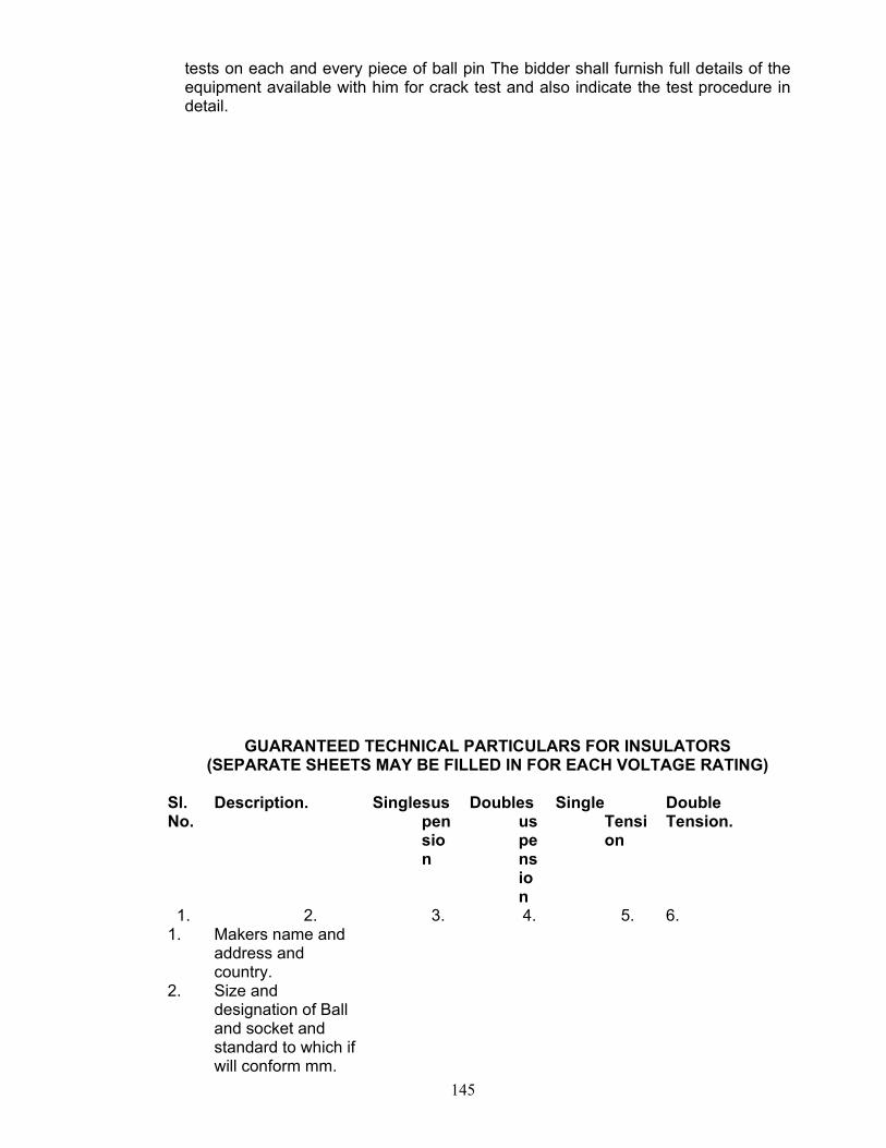
145
tests on each and every piece of ball pin The bidder shall furnish full details of the equipment available with him for crack test and also indicate the test procedure in detail.
GUARANTEED TECHNICAL PARTICULARS FOR INSULATORS (SEPARATE SHEETS MAY BE FILLED IN FOR EACH VOLTAGE RATING)
Sl. No.
Description. Singlesuspension
Doublesuspension
Single Tension
Double Tension.
1. 2. 3. 4. 5. 6. 1. Makers name and
address and country.
2. Size and designation of Ball and socket and standard to which if will conform mm.
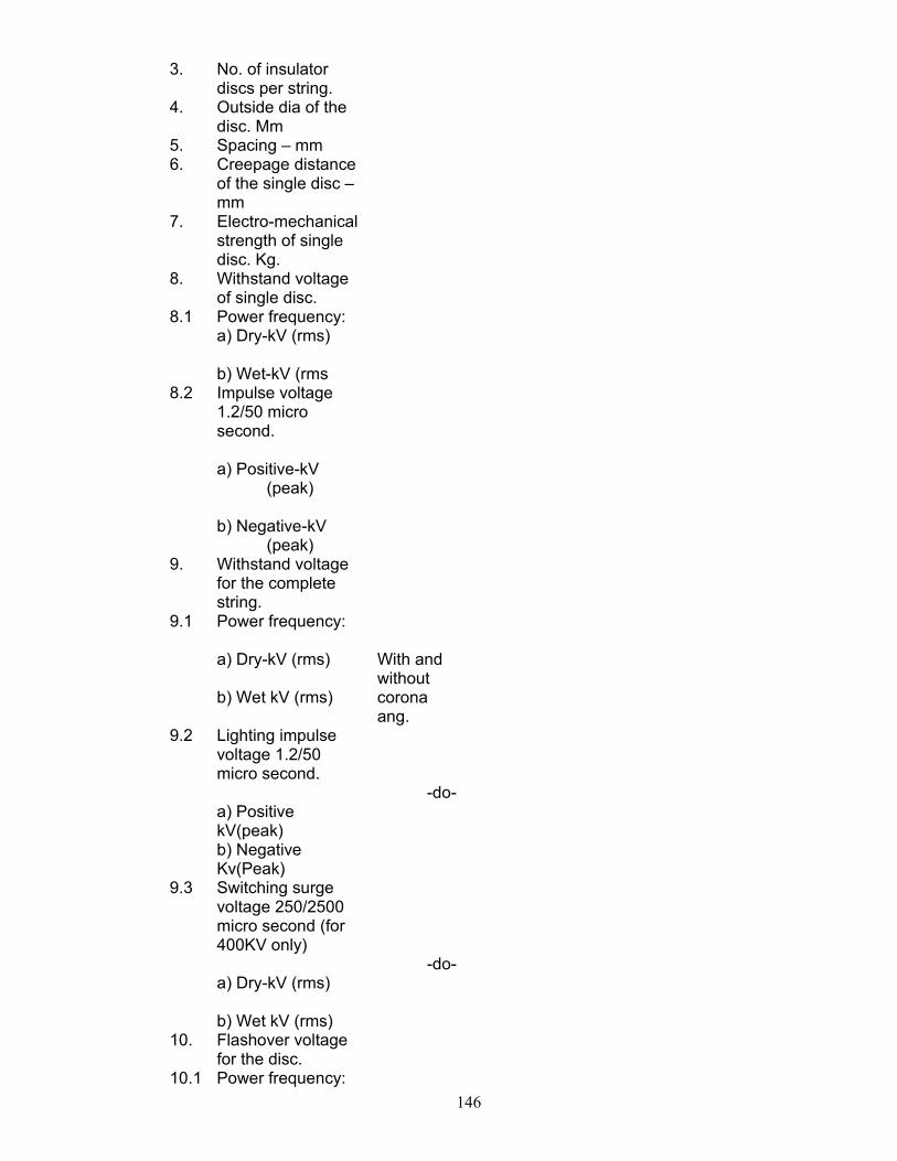
146
3. No. of insulator discs per string.
4. Outside dia of the disc. Mm
5. Spacing – mm 6. Creepage distance
of the single disc –mm
7. Electro-mechanical strength of single disc. Kg.
8. Withstand voltage of single disc.
8.1 Power frequency: a) Dry-kV (rms)
b) Wet-kV (rms
8.2 Impulse voltage 1.2/50 micro second.
a) Positive-kV
(peak)
b) Negative-kV (peak)
9. Withstand voltage for the complete string.
9.1 Power frequency:
a) Dry-kV (rms)
b) Wet kV (rms)
With and without corona ang.
9.2 Lighting impulse voltage 1.2/50 micro second.
a) Positive kV(peak) b) Negative Kv(Peak)
-do-
9.3 Switching surge voltage 250/2500 micro second (for 400KV only)
a) Dry-kV (rms)
b) Wet kV (rms)
-do-
10. Flashover voltage for the disc.
10.1 Power frequency:
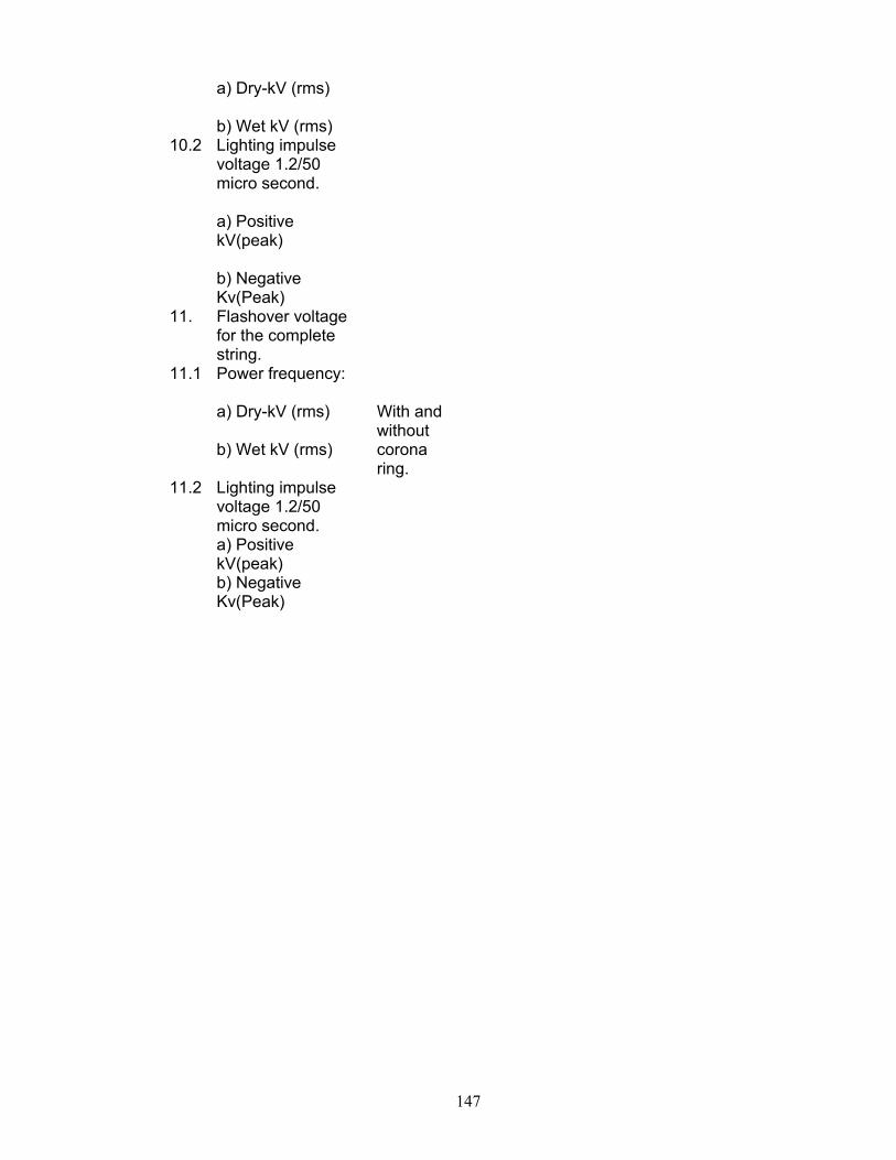
147
a) Dry-kV (rms)
b) Wet kV (rms)
10.2 Lighting impulse voltage 1.2/50 micro second.
a) Positive kV(peak)
b) Negative Kv(Peak)
11. Flashover voltage for the complete string.
11.1 Power frequency:
a) Dry-kV (rms)
b) Wet kV (rms)
With and without corona ring.
11.2 Lighting impulse voltage 1.2/50 micro second. a) Positive kV(peak) b) Negative Kv(Peak)
148
SECTION-XIV
HARDWARES
149
TECHNICAL SPECIFICATION FOR HARDWARE FITTINGS.
SUITABLE FOR GALVANISED STEEL STRANDED GROUNDWIRE (7/3.15mm) ACCESSORIES AND POWER CONDUCTOR (ACSR PANTHER) AND ACSR ZEBRA, 1.0 SCOPE This Specification covers design (if required), manufacture, testing at manufacturer’s
Works, supply and delivery of GSS), power conductor and ground wire accessories,
insulator and hardware fittings for string insulators suitable for use in 132 KV Over-head
transmission lines of OPTCL. The hard wares to be supplied shall be as per approved
drawings of OPTCL. Any change there of shall be with due permission of Sr. G.M
(CPC).The firm shall submit his drawings for approval of OPTCL and only after which the
manufacturing shall be started.
The materials/equipment offered, shall be complete with all components, which are necessary or
usual for the efficient performance and satisfactory maintenance. Such part shall be deemed to be
within the scope of contract.
2.0 STANDARDS
The materials covered under this Specification shall comply with the requirement of the
latest version of the following standards as amended upto date, except where specified
otherwise.
i) IS;2486 Part-II & III : Insulator fitting for overhead power lines with a nominal voltage greater than 1,000 volts.
ii) IS:2121 Part I & II Conductor & earth wire accessories for overhead power lines.
iii) IS:9708 Stock Bridge Vibration Dampers on overhead power lines.
150
iv) IS:2633 Method of testing of uniformity of coating on zinc coated articles
v) IS:209 Specification for Zinc.
vi) BS:916 Specification for Hexagonal bolts and nuts.
3.0 MATERIALS AND DESIGN Aluminium and aluminium alloys, malleable iron and forget steel, having required mechanical
strength, corrosion resistance and machinability depending on the types of application for which
accessories / fittings are needed, shall be employed.
In manufacturer of the accessories / fittings, the composition of the aluminium alloys
used shall be made available to Employer if required for verification.
The materials offered shall be of first class quality, workmanship, well finished and approved
design. All castings shall be free from blow-holes, flaws, cracks of other defects and shall be
smooth, close grained and true forms and dimensions. All machined surfaces should be free,
smooth and well finished.
Metal fittings of specified material for conductor and earthwire accessories and string insulator
fittings are required to have excellent mechanical properties such as strength, toughness and high
resistance against corrosion. All current carrying parts shall be so designed and manufactured that
contact resistance is reduced to the minimum.
All bolts, nuts, bolt-heads shall be the white worths standard thread. Bolt heads and nuts shall be
hexagonal. Nuts shall be locked in an approved manner. The treads in nuts and tapped holes shall
be cut after galvanising an shall be well fabricated and greased. All other treads shall be cut before
galvanising. The bolt treads shall be undercut to take care of increase in diameter due to
galvanising.
All nuts shall be made of materials to Clause 4.8 of IS:1367 (latest edition) with regard to its
mechanical properties.
The general design conductor and earthe wire accessories and insulator fittings shall be such as to
ensure uniformity, high strength, free from corona formation and high resistance against corrosion
even in case of high level of atmosphere pollution.
All hooks, eyes, pins, bolts, suspension clamps and other fittings for attaching to the tower or to the
line conductor or to the earthwire shall be so designed that the effects of vibration, both on the
conductor and the fittings itself, are minimized.
Special attention must be given to ensure smooth finished surface throughout. Adequate bearing
area between fittings shall be provided and point or line contacts shall be avoided.

151
All accessories and hardwares shall be free from cracks, shrinks, slender air holes, burrs or rough
edges.
The design of he accessories and hardwares shall be such as to avoid local corona formation or
discharge likely to cause interference to tele-transmission signals of any kind.
4.0 GALVANISING : All ferrous parts of conductor and ground wire accessories and insulator hardwares
shall be galvanised in accordance with IS:2629-Recommended Practice for hot dip
galvanising of iron and steel or any other equivalent authoritive standards. The weight of
zinc coating shall be determined as per method stipulated in IS:2633 for testing weights,
thickness and uniformity of coating of hot dip galvanished articles or as per any other
equivalent authoritative standards. The zinc used or galvanisation shall conform to grade zn
98 of IS:209. The galvanised parts shall withstand four (4) dips of 1 minute each time while
testing uniformity of zinc coating as per IS:2633.
Spring washers shall be elctro galvanised.
5.0 ACCESSORIES FOR CONDUCTOR AND GROUND WIRE,
MID SPAN COMPRESSION JOINTS:FOR ACSR PANTHER ,ZEBRA, AAAC PANTHER, AAAC ZEBRA AND GROUNDWIRE OF 7/3.15 Sq.mm.
The Mid-Span Joints for conductor and earthwire shall be of compression type. The
conductor mid-span joints shall comprise of outer aluminium sleeve of extruded
aluminium (99.5% purity) and inner sleeve HDG Steel. All filler plug shall also be
provided. The ground wire mid-span joints shall be of HDG steel. The sleeves shall be
of circular shape suitable for compression into hexagonal shape.
The compression type mid-span straight joints shall be suitable for making joints in
the ACSR “PANTHER” conductor or in the galvanised steel stranded ground wire.
The joints shall be so designed that when installed no air space is left within the
finished joints. The joints shall have the conductivity as specified in relevant Clause.
The joints shall conform to IS:2121 (latest edition) unless speciried otherwise. The
details of the joints both suitable for ACSR Panther and ground wire are given in the
technical particulars.
The inner and outer diameters and lengths of the offered joints before and after
compression shall be clearly shown in the drawings.
152
6.0 VIBRATION DAMPER FOR ACSR PANTHER, AND GROUND WIRE(7/3.15)
Vibration Damper having 4 resonance frequency characteristic commonly called 4R
Damper shall be offered. The Damper shall eliminate fatigue on the conductor due to
vibration and damp out the vibration effectively so that no damage due to vibration is
caused to conductor / ground wire / string.
The dampers are proposed to be used at all tension locations and also at suspension
locations. One or more dampers are proposed to be used on tension/suspension locations
depending upon the span.
Bidder shall also recommend the number of damper required to effectively damp out
conductor or ground wire vibration for different values of span lengths and the distance
of fixation.
Vibration dampers shall be of approved design. The clamps of the vibration dampers
shall be made of aluminium alloy, so designed as to prevent any damage while fixing on
the conductor during erection or in continued operation. The fastening bolts should be
approved by the Employer. The spring washers should be elctro galvanised and of
minimum 2 mm thickness.
The messenger cable shall be made from high tensile strength steel strands in order to
prevent subsequent drop of weight in service.
Clamping bolts shall be provided with self locking nuts as designed to prevent
corrosion of the threads. All ferrous parts including the messenger cable shalal be bot
dip galvanised. The end of the messenger cable shall be effectively sealed to prevent
corrosion.
The vibration dampers and its attachment shall have smooth surface so that no
corona occurs on them.
The clamps of the stock bridge vibration dampers shall be so designed that in case of
loosening of the bolt or changing free parts of the clamp, it does not allow the damper to
disengage from the conductor.
7.0 REPAIR SLEEVE FOR ACSR PANTHER AND GROUNDWIRE :
Compression type repair sleeves shall be offered to provide reinforcement for conductor
with broken or damaged aluminium strands/galvanished steel ground wire broken in
damaged steel strands. The repair sleeve shall be designed to make good a conductor of
which not more than one-sixth (1/6th) of the strands in the outermost layer and damaged
or severed. The repair sleeves after compression should present a smooth surface.
153
8.0 SUSPENSION CLAMPS : FOR GROUND WIRE Suspension 4.3.19. In clamps for suitable size are require for holding the galvanised
steel stranded ground wire at suspension points. The suspension clamps shall be
suspended from the lower hanger or ‘D’ belt of 16 mm. dia. And should, therefore, be
supplied with a suitable attached that would allow the clamps to swing freely both in the
transverse and longitudinal direction. The clamps shall be so designed that the effect of
vibration both on the groundwire and the fittings itself is minimum.
The clamps shall be manufactured and finished so as to avoid sharp radia of
curvature, ridges which might lead to localized pressure and damage the ground wire in
service.
The clamps shall be made of heat treat malleable iron one Eye hook made of forced
steel. The entire assembly shall be hot dip galvanised.
The clamping surface shall be smooth and formed to support the groundwire on long
easy curves to take care or required steel vertical and horizontal angles.
The clamps shall permit the groundwire to slip before the failure of the latter occurs.
The leg of U-bolt holding the keeper piece of the clamps shall be kept sufficient long
and shall be provided with threads, nuts and locking nuts for fixing the flexible earthing
hond between the suspension clamps and tower structures.
9.0 TENSION CLAMPS (DEAD AND ASSEMBLY) FOR GROUND
WIRE. Compression type dead end assembly of G.S.S. ground wire shall be required for use
on the tension towers. The dead end assembly shall be supplied with complete jumper
terminals, nuts and bolts suitable link pieces between the steel clevis and tower strain
plates so as to provide sufficient flexibility not less than that of G.S.S. ground wire and
the tensile strength not less than 90% that of the G.S.S. ground wire.
The assemblies shall comprise of compression type dead end clamps and one anchor
shackle made of forget steel. The entire assembly shall be hot dip galvanised.
154
One of bolt holding joint per terminal of dead end assemblies shall be kept
sufficiently long and threaded and shall be provided with nuts, washers and locking nuts
for fixing the flexible earthing bond between the dead-end clamp and tower structures.
10.0 BONDING PIECES (FLEXIBLE COPPER EARTHING BOND
FOR EARTHWIRE 7/3.15mm) The tenderer shall offer flexible copper earthing bonding pieces for connecting the
ground wire suspension and tension clamps and tower legs suitable for earthing.
Each bond piece shall have suitable compression type galvanises steel lug or thimble
on either and for making connections to clamp and tower legs. The size, strength, etc. of
the bonding piece is given in this Specification.
11.0 INSULATOR HARDWARES The insulator disc hardwares and string assemblies to be offered by the tenderer shall be
suitable to meet the requirement given in the specific technical particulars as detailed
hereinafter.
Hardwares for suspension and tension insulator shall be suitable for insulator with
normal pin shank diameter of 20 mm. in case of tension string unit and 16mm. for
suspension string unit.
Each insulator string shall generally include the following hardware components.
Single Suspension Set.
Double Suspension Set.
a) Ball Hook
a) Ball Hook.
b) tower side arcing horn b) Socket clevis with R-Type security clip-3 Nos.
c) Socket Eye with R-Type security clip.
c) Yoke Plate-2 Nos.
d) Line side arcing horn. d) Tower side arcing horns-2Nos.
e) Armour grip suspension clamps e) Ball clevis – 2 Nos. f) Line side arcing homs-2 Nos. g) Clevis Eye. h) Armour Grip Suspension Clamp.
Single Tension Set : Double Tension Set :
155
a) Anchor Shackle. a) Anchor Shackle.
b) Ball Eye. b) Chain Link.
c) Tower side arcing horn. c) Yoke Plate – 2 Nos.
d) Socket Clevis with R-Type security clip.
d) Tower side arching horn.
e) Line side arcing horn e) Ball Clevis – 2 Nos.
f) Compression type dead end clamp.
f) Socket Clevis with R-Type security clip – 2 Nos.
g) Line side arcing horns.
h) Compression type dead end clamps.
12.0 CLAMP
12.1 ARMOUR GRIP SUSPENSION CLAMPS Armour Grip Suspension Clamp shall consist of 2 neoprene insert, one set of armour rods
made of aluminium alloy, two aluminium housing having inner profile matching with the profile of
the armour rods page and supporting strap made of aluminium alloy. The A.G. type suspension
clamp shall be designed, manufactured and finished as to have a suitable shape without sharp edges
at the end and to hold the respective conductor properly. It should, however, have sufficient contact
surface to minimise damagedue to fault current. The clamp shall be or Armour Grip Type.
The A.G. type suspension clamp shall permit the conductor to slip before the occurrence of
failure of the conductor and shall have sufficient slip strength to resist the conductor tension under
broken wire conditions. The clamp shall have slip strength of not less than 15 % of respective
conductors.
12.2 TENSION CLAMPS
The Tension Clamps shall be made out of aluminium alloy and of compression type suitable
for PANTHER conductor. The tension clamps shall not permit slipping or damage to failure of the
complete conductor or any part thereof at a load less than 90% of the ultimate strength of
conductor. The mechanical efficiency of tension / clamps shall not be affected by method of
erection involving come / along or similar clamps or tension stringing operation during or after
assembly and erection of tension clamp itself. The tension clamp shall be of a design that will
ensure unrestricted flow of current without use of parallel groove clamps.
The clamps shall be as light as possible.
12.3 ARCING HORNS
156
Each hardware assembly shall have provision for attaching arcing horns of both adjustable
and non/adjustable type across the suspension and tension strings or tower side. However each
hardware assembly shall be provided with arching horn of fixed type on line side only.
12.4 UNIVERSAL JOINTING COMPOUND
BENDEX-HV’ Universal jointing compound which is a chemically inert compound to be used
as filler for the compression joints and dead end clamps to be supplied.
TESTS, TEST CERTIFICATE AND PERFORMANCE REPORTS The fittings and accessories for the power conductor and G.S.S. ground wire, insulator and
hardwares shall be tested in accordance with IS:2121, IS:2486, IS:9708 (For V Dampers), BS:916
for hexagonal bolts and nuts or any other authoritative equivalent standards. Six sets of type and
routine test certificates and performance reports are to be submitted by the bidder.
The Employer however, reserves the right to get all the tests performed in accordance with the
relevant I.S. Specification as Acceptance Test in presence of Employer-s representatives.
The tenderer shall clearly state the testing facilities available in the laboratory at his Works and his
ability to carry out the tests in accordance with this Specification. All the specified tests shall be
carried out without any extra cost.
Acceptance Test for power conductor and G.S.S. ground wire accessories.
a) Visual examination
b) Dimensional verification
c) Failing load test
d) Slip strength test (for clamps)
e) Electrical resistance test
f) Resonance frequency test (for vibration dampers)
g) Fatigue test (for vibration dampers)
h) Mass pull off test (for vibration dampers)
i) Galvanising test.
13.1 ACCEPTANCE TEST FOR HARDWARES a) Dimensional verification.
b) Ultimate tensile test.
c) Slip strength test.
d) Electrical resistance test.
e) Heating cycle test
157
f) Breaking strength of full string assembly.
g) Galvanising test.
13.2 SPECIFIC TECHNICAL REQUIREMENTS FOR CONDUCTOR
ACCESSORIES AND INSULATOR HARDWARES
Conductor Panther/zebra GSS ground wire a) Type
b) Material c) Strand & Wire
diameter. d) Weight per Km. e) Overall diameter f) A.C. Resistance at
20 deg. C when corrected to standard weight.
g) Minimum
Breaking load/Ultimate tensile strength.
h) Maximum
working tension at minimum temperature & 2/3 full wind.
i) Maximum Sag at
maximum temperature & no wind.
ACSR Panther/zebra Aluminium conductor steel reinforced. Aluminium 30/3mm Steel 7/3mm & all.54/3.18mm steel-7/3.18mm resp. 974/1622 Kg/Km. 21/28.62 mm 0.13750/0.06915 Ohms/Km. 144/13289 Kg 3806/4325 Kg. 6120/9240 mm.
Ground wire. Galvanised stranded steel wire. 7/3.15 mm. 426 Kg/Km. 9.4mm. 5710 Kg. 1393 Kg. 5150mm.
DISC Insulator (for suspension & tension Insulator strings) Disc Insulators Suspension 132KV Tension 132KV a) Type
b) Ball size Ball & Socket 16mm. Alt. B
Ball & Socket. 20mm. Alt. B/20mm
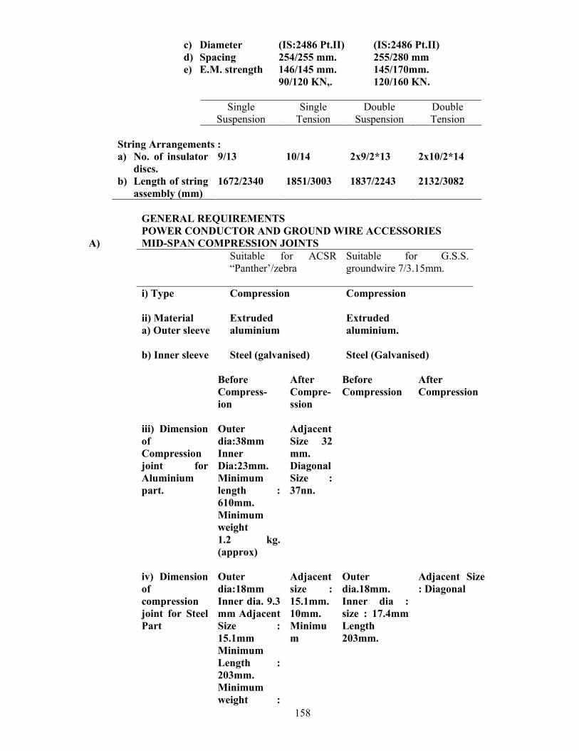
158
c) Diameter d) Spacing e) E.M. strength
(IS:2486 Pt.II) 254/255 mm. 146/145 mm. 90/120 KN,.
(IS:2486 Pt.II) 255/280 mm 145/170mm. 120/160 KN.
Single
Suspension Single
Tension Double
Suspension Double Tension
String Arrangements : a) No. of insulator
discs. b) Length of string
assembly (mm)
9/13 1672/2340
10/14 1851/3003
2x9/2*13 1837/2243
2x10/2*14 2132/3082
GENERAL REQUIREMENTS POWER CONDUCTOR AND GROUND WIRE ACCESSORIES A) MID-SPAN COMPRESSION JOINTS Suitable for ACSR
“Panther’/zebra
Suitable for G.S.S. groundwire 7/3.15mm.
i) Type ii) Material a) Outer sleeve
Compression Extruded aluminium
Compression Extruded aluminium.
b) Inner sleeve
Steel (galvanised) Steel (Galvanised)
Before Compress-ion
After Compre-ssion
Before Compression
After Compression
iii) Dimension of Compression joint for Aluminium part.
Outer dia:38mm Inner Dia:23mm. Minimum length : 610mm. Minimum weight 1.2 kg. (approx)
Adjacent Size 32 mm. Diagonal Size : 37nn.
iv) Dimension
of compression joint for Steel Part
Outer dia:18mm Inner dia. 9.3 mm Adjacent Size : 15.1mm Minimum Length : 203mm. Minimum weight :
Adjacent size : 15.1mm. 10mm. Minimum
Outer dia.18mm. Inner dia : size : 17.4mm Length 203mm.
Adjacent Size : Diagonal
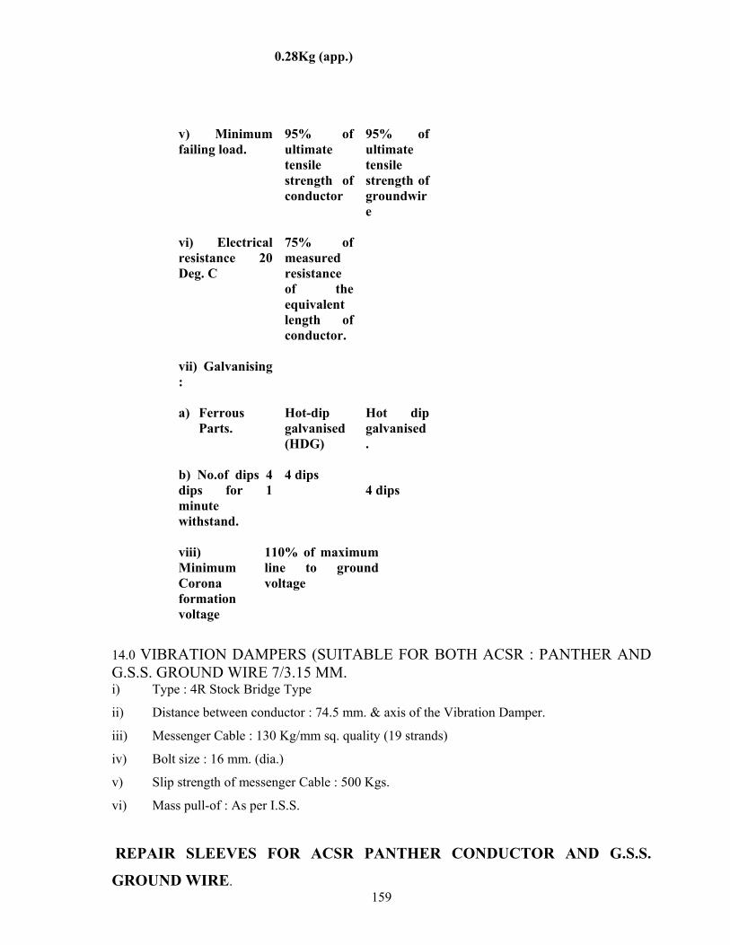
159
0.28Kg (app.)
v) Minimum
failing load. 95% of ultimate tensile strength of conductor
95% of ultimate tensile strength of groundwire
vi) Electrical resistance 20 Deg. C
75% of measured resistance of the equivalent length of conductor.
vii) Galvanising :
a) Ferrous
Parts. b) No.of dips 4 dips for 1 minute withstand.
Hot-dip galvanised (HDG) 4 dips
Hot dip galvanised. 4 dips
viii)
Minimum Corona formation voltage
110% of maximum line to ground voltage
14.0 VIBRATION DAMPERS (SUITABLE FOR BOTH ACSR : PANTHER AND G.S.S. GROUND WIRE 7/3.15 MM. i) Type : 4R Stock Bridge Type
ii) Distance between conductor : 74.5 mm. & axis of the Vibration Damper.
iii) Messenger Cable : 130 Kg/mm sq. quality (19 strands)
iv) Bolt size : 16 mm. (dia.)
v) Slip strength of messenger Cable : 500 Kgs.
vi) Mass pull-of : As per I.S.S.
REPAIR SLEEVES FOR ACSR PANTHER CONDUCTOR AND G.S.S.
GROUND WIRE.
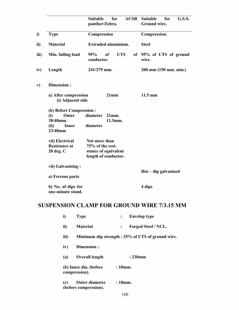
160
Suitable for ACSR panther/Zebra.
Suitable for G.S.S. Ground wire.
i) Type Compression Compression.
ii) Material Extruded aluminium. Steel
iii) Min. failing load 95% of UTS of conductor.
95% of UTS of ground wire.
iv) Length 241/279 mm. 200 mm (150 mm. min.)
v) Dimension :
a) After compression (i) Adjacent side
(b) Before Compression : (i) Outer diameter 38/48mm. (ii) Inner diameter 23/40mm
21mm 21mm. 11.5mm.
11.5 mm
vii) Electrical
Resistance at 20 deg. C
Not more than 75% of the resi- stance of equivalent length of conductor.
vii) Galvanising : a) Ferrous parts
Hot – dip galvanised
b) No. of dips for one-minute stand.
4 dips
SUSPENSION CLAMP FOR GROUND WIRE 7/3.15 MM i) Type : Envelop type ii) Material : Forged Steel / NCL.
iii) Minimum slip strength : 25% of UTS of ground wire. iv) Dimension :
(a) Overall length : 230mm (b) Inner dia. (before : 10mm. compression). (c) Outer diameter : 18mm. (before compression).
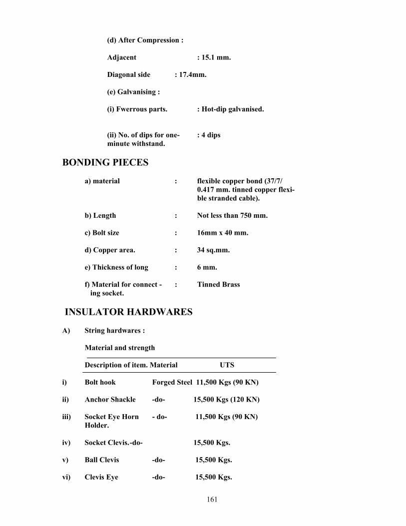
161
(d) After Compression : Adjacent : 15.1 mm. Diagonal side : 17.4mm. (e) Galvanising : (i) Fwerrous parts. : Hot-dip galvanised. (ii) No. of dips for one- : 4 dips minute withstand.
BONDING PIECES
a) material : flexible copper bond (37/7/ 0.417 mm. tinned copper flexi- ble stranded cable). b) Length : Not less than 750 mm. c) Bolt size : 16mm x 40 mm. d) Copper area. : 34 sq.mm. e) Thickness of long : 6 mm. f) Material for connect - : Tinned Brass ing socket.
INSULATOR HARDWARES A) String hardwares :
Material and strength Description of item. Material UTS
i) Bolt hook Forged Steel 11,500 Kgs (90 KN) ii) Anchor Shackle -do- 15,500 Kgs (120 KN) iii) Socket Eye Horn - do- 11,500 Kgs (90 KN) Holder. iv) Socket Clevis. -do- 15,500 Kgs. v) Ball Clevis -do- 15,500 Kgs. vi) Clevis Eye -do- 15,500 Kgs.
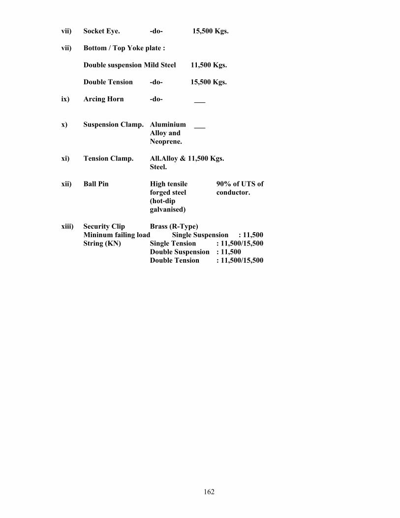
162
vii) Socket Eye. -do- 15,500 Kgs. vii) Bottom / Top Yoke plate :
Double suspension Mild Steel 11,500 Kgs. Double Tension -do- 15,500 Kgs.
ix) Arcing Horn -do- ___ x) Suspension Clamp. Aluminium ___ Alloy and Neoprene. xi) Tension Clamp. All.Alloy & 11,500 Kgs. Steel. xii) Ball Pin High tensile 90% of UTS of forged steel conductor. (hot-dip galvanised) xiii) Security Clip Brass (R-Type) Mininum failing load Single Suspension : 11,500 String (KN) Single Tension : 11,500/15,500 Double Suspension : 11,500 Double Tension : 11,500/15,500
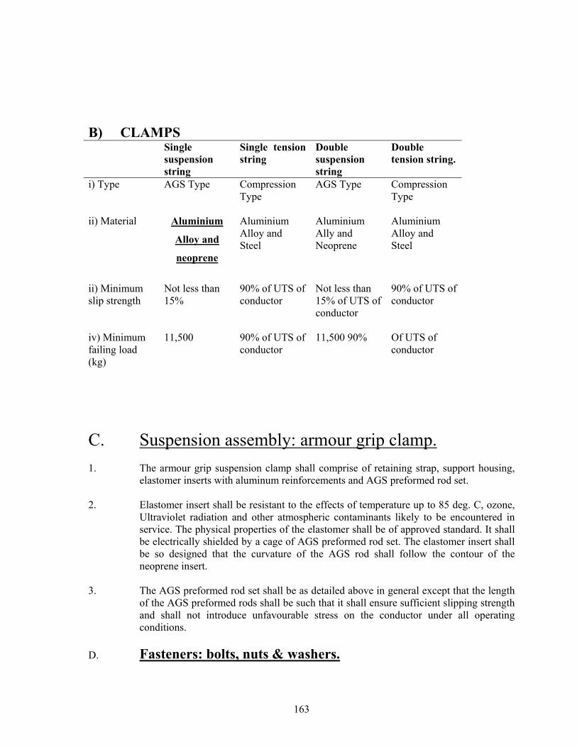
163
B) CLAMPS Single
suspension string
Single tension string
Double suspension string
Double tension string.
i) Type AGS Type Compression Type
AGS Type Compression Type
ii) Material Aluminium
Alloy and
neoprene
Aluminium Alloy and Steel
Aluminium Ally and Neoprene
Aluminium Alloy and Steel
ii) Minimum slip strength
Not less than 15%
90% of UTS of conductor
Not less than 15% of UTS of conductor
90% of UTS of conductor
iv) Minimum failing load (kg)
11,500
90% of UTS of conductor
11,500 90% Of UTS of conductor
C. Suspension assembly: armour grip clamp. 1. The armour grip suspension clamp shall comprise of retaining strap, support housing,
elastomer inserts with aluminum reinforcements and AGS preformed rod set. 2. Elastomer insert shall be resistant to the effects of temperature up to 85 deg. C, ozone,
Ultraviolet radiation and other atmospheric contaminants likely to be encountered in service. The physical properties of the elastomer shall be of approved standard. It shall be electrically shielded by a cage of AGS preformed rod set. The elastomer insert shall be so designed that the curvature of the AGS rod shall follow the contour of the neoprene insert.
3. The AGS preformed rod set shall be as detailed above in general except that the length
of the AGS preformed rods shall be such that it shall ensure sufficient slipping strength and shall not introduce unfavourable stress on the conductor under all operating conditions.
D. Fasteners: bolts, nuts & washers.
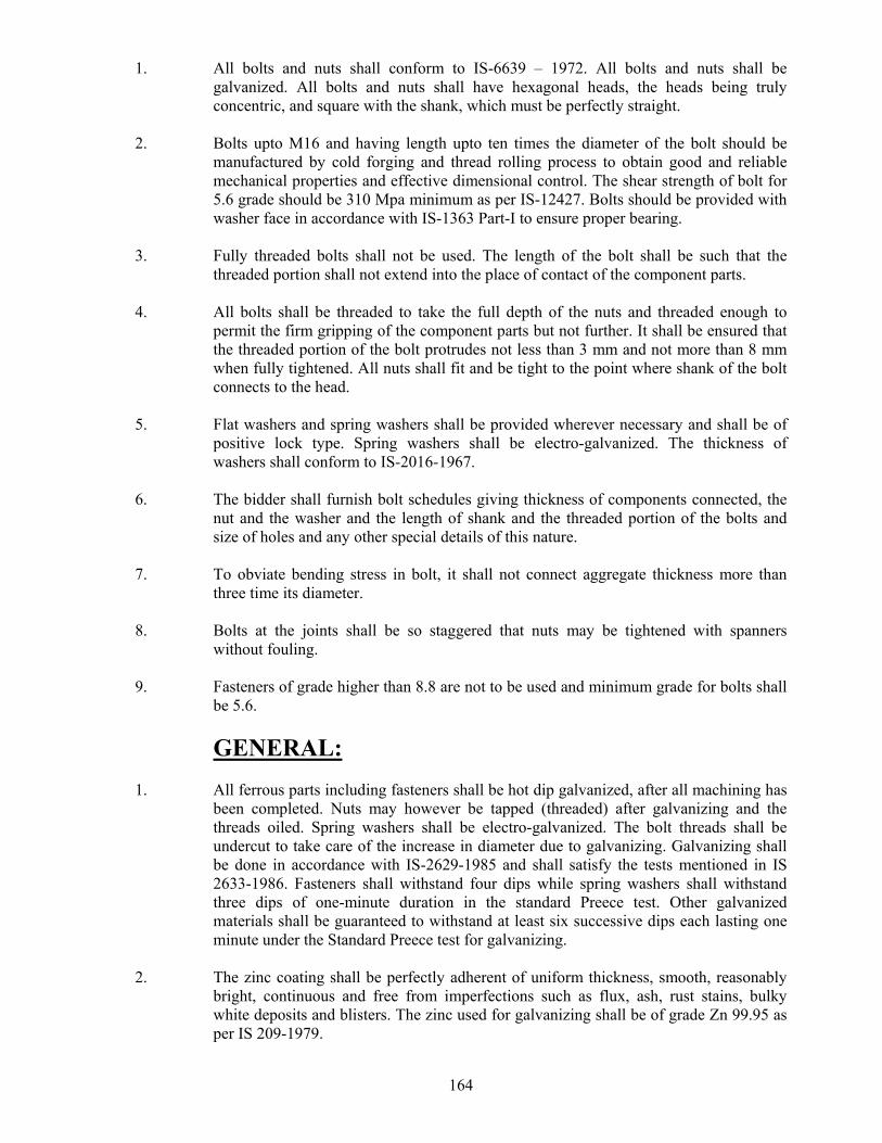
164
1. All bolts and nuts shall conform to IS-6639 – 1972. All bolts and nuts shall be galvanized. All bolts and nuts shall have hexagonal heads, the heads being truly concentric, and square with the shank, which must be perfectly straight.
2. Bolts upto M16 and having length upto ten times the diameter of the bolt should be
manufactured by cold forging and thread rolling process to obtain good and reliable mechanical properties and effective dimensional control. The shear strength of bolt for 5.6 grade should be 310 Mpa minimum as per IS-12427. Bolts should be provided with washer face in accordance with IS-1363 Part-I to ensure proper bearing.
3. Fully threaded bolts shall not be used. The length of the bolt shall be such that the
threaded portion shall not extend into the place of contact of the component parts. 4. All bolts shall be threaded to take the full depth of the nuts and threaded enough to
permit the firm gripping of the component parts but not further. It shall be ensured that the threaded portion of the bolt protrudes not less than 3 mm and not more than 8 mm when fully tightened. All nuts shall fit and be tight to the point where shank of the bolt connects to the head.
5. Flat washers and spring washers shall be provided wherever necessary and shall be of
positive lock type. Spring washers shall be electro-galvanized. The thickness of washers shall conform to IS-2016-1967.
6. The bidder shall furnish bolt schedules giving thickness of components connected, the
nut and the washer and the length of shank and the threaded portion of the bolts and size of holes and any other special details of this nature.
7. To obviate bending stress in bolt, it shall not connect aggregate thickness more than
three time its diameter. 8. Bolts at the joints shall be so staggered that nuts may be tightened with spanners
without fouling. 9. Fasteners of grade higher than 8.8 are not to be used and minimum grade for bolts shall
be 5.6. GENERAL: 1. All ferrous parts including fasteners shall be hot dip galvanized, after all machining has
been completed. Nuts may however be tapped (threaded) after galvanizing and the threads oiled. Spring washers shall be electro-galvanized. The bolt threads shall be undercut to take care of the increase in diameter due to galvanizing. Galvanizing shall be done in accordance with IS-2629-1985 and shall satisfy the tests mentioned in IS 2633-1986. Fasteners shall withstand four dips while spring washers shall withstand three dips of one-minute duration in the standard Preece test. Other galvanized materials shall be guaranteed to withstand at least six successive dips each lasting one minute under the Standard Preece test for galvanizing.
2. The zinc coating shall be perfectly adherent of uniform thickness, smooth, reasonably
bright, continuous and free from imperfections such as flux, ash, rust stains, bulky white deposits and blisters. The zinc used for galvanizing shall be of grade Zn 99.95 as per IS 209-1979.
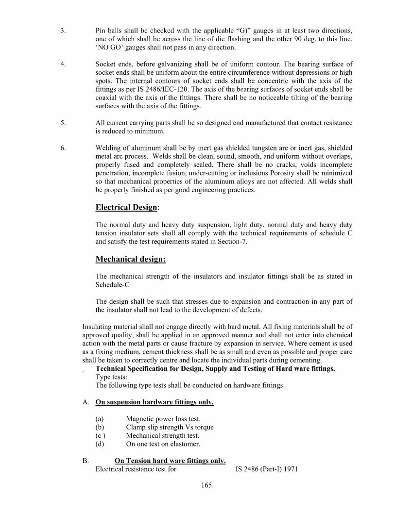
165
3. Pin balls shall be checked with the applicable “G)” gauges in at least two directions, one of which shall be across the line of die flashing and the other 90 deg. to this line. ‘NO GO’ gauges shall not pass in any direction.
4. Socket ends, before galvanizing shall be of uniform contour. The bearing surface of
socket ends shall be uniform about the entire circumference without depressions or high spots. The internal contours of socket ends shall be concentric with the axis of the fittings as per IS 2486/IEC-120. The axis of the bearing surfaces of socket ends shall be coaxial with the axis of the fittings. There shall be no noticeable tilting of the bearing surfaces with the axis of the fittings.
5. All current carrying parts shall be so designed end manufactured that contact resistance
is reduced to minimum. 6. Welding of aluminum shall be by inert gas shielded tungsten are or inert gas, shielded
metal arc process. Welds shall be clean, sound, smooth, and uniform without overlaps, properly fused and completely sealed. There shall be no cracks, voids incomplete penetration, incomplete fusion, under-cutting or inclusions Porosity shall be minimized so that mechanical properties of the aluminum alloys are not affected. All welds shall be properly finished as per good engineering practices.
Electrical Design:
The normal duty and heavy duty suspension, light duty, normal duty and heavy duty tension insulator sets shall all comply with the technical requirements of schedule C and satisfy the test requirements stated in Section-7.
Mechanical design:
The mechanical strength of the insulators and insulator fittings shall be as stated in Schedule-C
The design shall be such that stresses due to expansion and contraction in any part of the insulator shall not lead to the development of defects.
Insulating material shall not engage directly with hard metal. All fixing materials shall be of approved quality, shall be applied in an approved manner and shall not enter into chemical action with the metal parts or cause fracture by expansion in service. Where cement is used as a fixing medium, cement thickness shall be as small and even as possible and proper care shall be taken to correctly centre and locate the individual parts during cementing. Technical Specification for Design, Supply and Testing of Hard ware fittings. Type tests: The following type tests shall be conducted on hardware fittings.
A. On suspension hardware fittings only. (a) Magnetic power loss test. (b) Clamp slip strength Vs torque (c ) Mechanical strength test. (d) On one test on elastomer. B. On Tension hard ware fittings only. Electrical resistance test for IS 2486 (Part-I) 1971
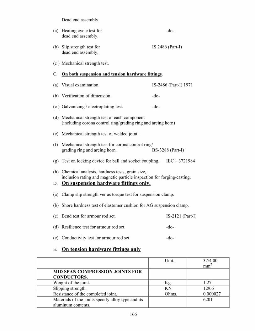
166
Dead end assembly. (a) Heating cycle test for -do- dead end assembly. (b) Slip strength test for IS 2486 (Part-I) dead end assembly. (c ) Mechanical strength test. C. On both suspension and tension hardware fittings. (a) Visual examination. IS-2486 (Part-I) 1971 (b) Verification of dimension. -do- (c ) Galvanizing / electroplating test. -do- (d) Mechanical strength test of each component (including corona control ring/grading ring and arcing horn) (e) Mechanical strength test of welded joint. (f) Mechanical strength test for corona control ring/ grading ring and arcing horn. BS-3288 (Part-I) (g) Test on locking device for ball and socket coupling. IEC – 3721984 (h) Chemical analysis, hardness tests, grain size, inclusion rating and magnetic particle inspection for forging/casting. D. On suspension hardware fittings only. (a) Clamp slip strength ver as torque test for suspension clamp. (b) Shore hardness test of elastomer cushion for AG suspension clamp. (c) Bend test for armour rod set. IS-2121 (Part-I) (d) Resilience test for armour rod set. -do- (e) Conductivity test for armour rod set. -do- E. On tension hardware fittings only Unit. 37/4.00
mm2 MID SPAN COMPRESSION JOINTS FOR CONDUCTORS.
Weight of the joint. Kg. 1.27 Slipping strength. KN 129.6 Resistance of the completed joint. Ohms. 0.000027 Materials of the joints specify alloy type and its aluminum contents.
6201
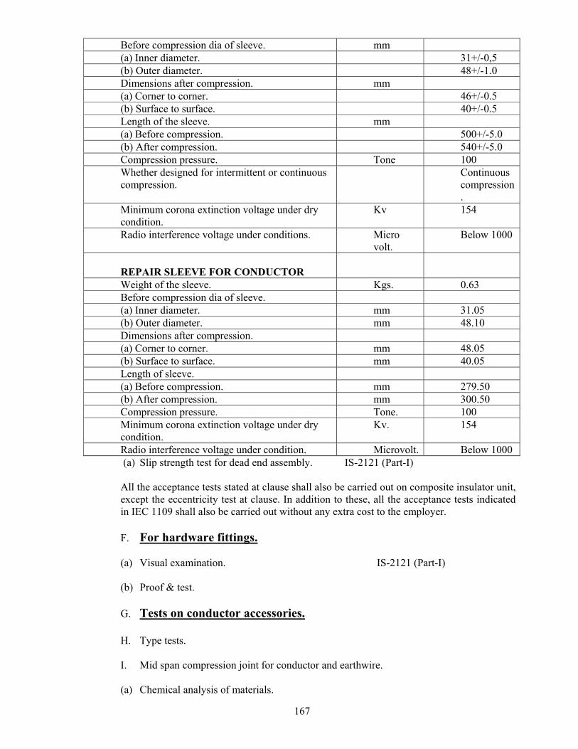
167
Before compression dia of sleeve. mm (a) Inner diameter. 31+/-0,5 (b) Outer diameter. 48+/-1.0 Dimensions after compression. mm (a) Corner to corner. 46+/-0.5 (b) Surface to surface. 40+/-0.5 Length of the sleeve. mm (a) Before compression. 500+/-5.0 (b) After compression. 540+/-5.0 Compression pressure. Tone 100 Whether designed for intermittent or continuous compression.
Continuous compression.
Minimum corona extinction voltage under dry condition.
Kv 154
Radio interference voltage under conditions. Micro volt.
Below 1000
REPAIR SLEEVE FOR CONDUCTOR
Weight of the sleeve. Kgs. 0.63 Before compression dia of sleeve. (a) Inner diameter. mm 31.05 (b) Outer diameter. mm 48.10 Dimensions after compression. (a) Corner to corner. mm 48.05 (b) Surface to surface. mm 40.05 Length of sleeve. (a) Before compression. mm 279.50 (b) After compression. mm 300.50 Compression pressure. Tone. 100 Minimum corona extinction voltage under dry condition.
Kv. 154
Radio interference voltage under condition. Microvolt. Below 1000 (a) Slip strength test for dead end assembly. IS-2121 (Part-I) All the acceptance tests stated at clause shall also be carried out on composite insulator unit, except the eccentricity test at clause. In addition to these, all the acceptance tests indicated in IEC 1109 shall also be carried out without any extra cost to the employer. F. For hardware fittings. (a) Visual examination. IS-2121 (Part-I) (b) Proof & test. G. Tests on conductor accessories. H. Type tests. I. Mid span compression joint for conductor and earthwire. (a) Chemical analysis of materials.
168
(b) Electrical resistance tests. IS-2121 (Part-II) 1981 clause 6.5 & 6.6 (c) Heating cycle test. -do- (d) Slip strength test. -do- (e) Corona extinction voltage test (dry) (f) Radio interference voltage test (dry) J. Repair sleeve for conductor. (a) Chemical analysis of materials.
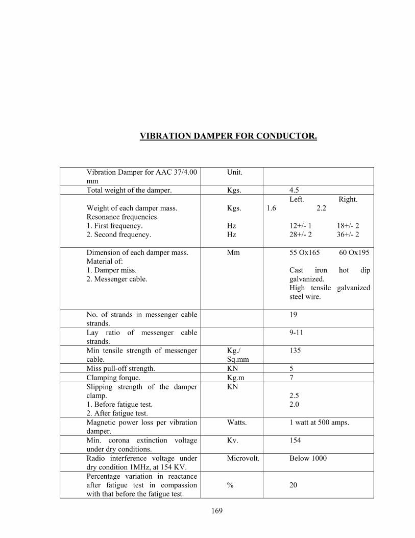
169
VIBRATION DAMPER FOR CONDUCTOR. Vibration Damper for AAC 37/4.00 mm
Unit.
Total weight of the damper. Kgs. 4.5 Weight of each damper mass. Resonance frequencies. 1. First frequency. 2. Second frequency.
Kgs. Hz Hz
Left. Right. 1.6 2.2
12+/- 1 18+/- 2 28+/- 2 36+/- 2
Dimension of each damper mass. Material of: 1. Damper miss. 2. Messenger cable.
Mm 55 Ox165 60 Ox195 Cast iron hot dip galvanized. High tensile galvanized steel wire.
No. of strands in messenger cable strands.
19
Lay ratio of messenger cable strands.
9-11
Min tensile strength of messenger cable.
Kg./ Sq.mm
135
Miss pull-off strength. KN 5 Clamping forque. Kg.m 7 Slipping strength of the damper clamp. 1. Before fatigue test. 2. After fatigue test.
KN
2.5 2.0
Magnetic power loss per vibration damper.
Watts. 1 watt at 500 amps.
Min. corona extinction voltage under dry conditions.
Kv. 154
Radio interference voltage under dry condition 1MHz, at 154 KV.
Microvolt. Below 1000
Percentage variation in reactance after fatigue test in compassion with that before the fatigue test.
%
20

170
171
CIVIL WORKS
172
CONSTRUCTION OF 132 KV LINE ON DC TOWERS
1.0 SCOPE-Construction of 132 KV on DC towers 2.0 SURVEY (detail & check, estimating of quantities & spotting of towers) 2.1 General: Preliminary route alignment in respect of the proposed transmission lines has been
fixed by the employer subject to alteration of places due to way leave or other unavoidable constraints.
2.1.1 Provisional quantities/numbers of different types of towers have been estimated and
indicated in the Activity Schedule given at the end of the specification. However final quantities for work shall be as determined by the successful bidder, on completion of the detail survey, preparation of route profile drawing and designing of the different types of towers as elaborated sin the specification and scope of work.
2.1.1.1 The contractor shall undertake detailed survey on the basis of the tentative alignment fixed
by the employer. The said preliminary alignment may, however, change in the interest of economy to avoid forest and hazards in work. While surveying the alternative route the following points shall be taken care by the contractor.
173
(a) The line is as near as possible to the available roads in the area. (b) The route is straight and short as far as possible. © Good farming areas, religious places, forest, civil and defence installations,
aerodromes, public and private premises, ponds, tanks, lakes, gardens, and plantations are avoided as far as practicable.
(d) The line is far away from telecommunication lines as reasonably possible.
Parallelism with these lines shall be avoided as far as practicable. (e) Crossing with permanent objects are minimum but where unavoidable preferably at
right angles. (f) Difficult and unsafe approaches are avoided. (g) The survey shall be conducted along the approved alignment only in accordance
with IS: 5613 (Part-II/Section-2), 1985. (h) For river crossing: Taking levels at 25 metre interval on bank of river and at 50
metre interval at bed of river so far as to show the true profile of the ground and river bed. The levels may be taken with respect to the nearest existing towers, pile foundation of towers, base or railway/road bridge, road culvert etc. The levels shall be taken at least 100 m. on either side of the crossing alignment. Both longitudinal and cross sectional shall be drawn preferably to a scale of 1:2000 at horizontal and 1:200 vertical.
After completing the detailed survey, the contractor shall submit the final profile and tower schedule for final approval of the employer. The final profile and tower schedule shall incorporate position of all type of towers. To facilitate checking of the alignment, suitable reference marks shall be provided. For this purpose, concrete pillars of suitable sizes shall be planted at all angle locations and suitable wooden/iron pegs shall be driven firmly at the intermediate points.; The contractor shall quote his rate covering these involved jobs. Only approved sag template shall be used for tower spotting and the final profiles.
2.1.1.2 PROFILE PLOTTING AND TOWER SPOTTING The profile shall be plotted and prepared to the scale 1 in 2,000 for horizontal and 1 in 200 for
vertical on squared (mm) paper. If somewhere the difference in levels be too high, the chart may be broken up according to the requirements. A 10 mm overlap shall be shown on each following sheet. The chart shall progress from left to right for convenience in handling. The sheet size may be conveniently chosen. With the help of sag template, final tower location shall be marked on the profiles and while locating the tower on survey chart, the following shall be kept in mind:
174
(a) The number of consecutive span between the section points shall not exceed 10
in case of straight run on a more or les plain stretch. (b) Individual span shall be as near as to the normal design ruling span.
In different crossing the contractor shall take into consideration the prevailing regulations of the respective authorities before finalizing type and location of the towers. While carrying out survey work, the contractor has to collect all relevant data, prepare and submit drawings in requisite number for obtaining clearance from the PTCC, road, aviation, railways, river and forest authorities.
The contractor shall remain fully responsible for the exact alignment of the line. If after erection,
any tower is found to be out of alignment, the same shall have to be dismantled and re-erected after corrosion by the contractor at his own cost, risk and responsibility, including installation of fresh foundation, if belt necessary by the employer.
After peg marking of the angle tower or tension towers, the contractor shall obtain approval from
the employer and thereafter pegging of suspension type tower shall be done by the contractor and pegging of all the four legs of each type of towers at all the locations shall be done.
2.1.1.3 SCHEDULE OF MATERIALS When the survey is approved, the contractor shall submit to the employer a complete detail
schedule of all materials to be used in the line. Size and length of conductor etc. are also to be given in the list. This schedule is very essential for finalizing the quantities of all line material. The contractor shall furnish the same.
2.1.1.4 CHECK SURVEY The contractor shall undertake the check survey during execution on the basis of the alignment
profile drawing and tower schedule approved by the employer. If during check survey necessity arises for minor change in route to eliminate way leave or other unavoidable constraints, the contractor may change the said alignment after obtaining prior approval from the employer.
The contractor, while carrying out the check survey, shall peg mark the power position on ground
conforming to the survey charts. In the process, it is necessary to have the pit centers marks according to the excavating marking charts to be prepared by the contractor and approved by the employer. The levels up or down of each pit center with respect to the center of the tower location shall be noted and recorded for determining the amount of earth work
175
required to meet the design. At the charting point of the route survey, an angle iron spite shall be driven firmly into the ground showing a little above the ground level.
2.1.1.5 WAY-LEAVE AND TREE CUTTING Way-leave permission which may be required by the contractor shall be arranged at his cost. While
submitting final-survey report for approval, proposals for way-leave right of way shall be submitted by the contractor. Employer may extend help to get the permission within a reasonable time as mutually agreed upon for which due notice shall be given by the contractor in such a way so that obtaining permission from appropriate authority do not hinder the continued and smooth progress of the work.
The employer shall not be held responsible for any claim on account of damage done by the
contractor or his personnel to trees, crops and other properties. The contractor shall take necessary precaution to avoid damage to any ripe and partially grown
crops and in the case of unavoidable damage, the employer shall be informed and necessary compensation shall be paid by the contractor.
In the event of any obstruction being encountered from local villagers or authorities, the contractor
shall immediately notify the employer who shall take steps, without any obligation to the contractor, as may be necessary, to clear the obstruction. The contractor or his representative shall not adopt antagonistic attitude towards the villagers or local authorities with whom employer for cases which cannot be settled amicably by them.
Trimming of tree branches or cutting of a few trees en-route during survey is within the scope of
survey to be done by the contractor. Contractor shall arrange for necessary way-leave and compensation in this regard. During erection of the line, compensation for tree cutting, damage caused to crops, actual cutting and felling of the trees including way-leave permission for such route clearance shall be arranged by the contractor at his cost. The contractor will identify the number of trees and detail of obstructions to be removed for erection of the line and intimate the employer well in advance in case of any help. Other related works like construction of temporary approach roads, etc. as required, shall be done by the contractor and the same will lie within the scope of contractor’s work and such cost shall be considered to be included in the rates quoted by him.
While quoting the rate for detailed and check survey as per bidding activity schedule, the contractor
shall include all costs involved in different activities described herein earlier. 2.0 SUB-SOIL INVESTIGATION To ascertain soil parameters in various stretch inter, the contractor shall carry out sub-soil
investigation through reputed soil consultant as approved by the employer. 2.1 SCOPE OF WORK The scope of sub-soil investigation covers execution of complete soil exploration for the
transmission line under this contract including boring, drilling, collection of undisturbed
176
soil sample where possible, otherwise disturbed samples, conducting laboratory test of soil samples to find out the various parameters as detailed in this specification and submission of detailed reports in 6 copies along with specific recommendation regarding suitable type of foundation for each bore-hole along with recommendation for soil improvement where necessary.
2.1.1 QUALIFYING REQUIREMENTS OF SOIL CONSULTANTS The soil consultants shall provide satisfactory evidence concerning the following as and when
asked for. That, he/they has/have adequate technical knowledge and previous practical experience in carrying
out complete soil investigation jobs in any kind of soil. That he/they has/have well equipped, modernized soil testing laboratory of his/their own. If asked
for by the employer, the contractor shall arrange inspection of such laboratory of the soil consultant by the representative of the employer.
If in the opinion of the employer, the soil consultant (proposed by the contractor) is not well
equipped or capable to undertake the sub-soil investigation job relating to this contract, then such soil consultant shall not be engaged to undertake the job. In that case, they shall have to engage other agency as will be approved by the employer.
2.1.2 TEST BORING The boring shall be done at the major locations/crossing, special towers. However, it is desirable
that there should be at least one sub-soil investigation bore-hole for the line. Such locations for sub-soil investigation shall be selected and finalized in consultation with the employer.
The test boring through different layers of all kinds of soil shall have to be carried out by the
contractor through the approved soil consultant as briefed hereunder.
(a) Method of boring, selection of sampling tubes, sampling, recording of boring, protection, handling, leveling of samples shall be done as specified in IS: 1892/1977, if any, after obtaining approval from the employer. The contractor/consultant shall furnish in the soil report in details, the equipment and method of boring actually adopted.
(b) Depth of boring below ground level shall be 15 M. only unless continuous bedrock
is encountered earlier. In case rock is encountered at any depth within 15 M. adequate study of rock and assessment of strength characteristics shall be done and recommendation shall be given.
(c) Undisturbed soil samples shall be obtained for the initial 4M depths at every 1.5M
interval and at change of strata. After these initial 4M depths, samples shall be obtained preferably at every 3M or where there is a change of strata, or as advised by the employer.
177
(d) In case collection of undisturbed samples becomes difficult/impossible detailed soil
testing on remoulded soil samples is to be considered and reported in the soil report.
(e) Standard penetration test as per IS: 2131 with latest amendment shall have to be conducted in different strata and recorded properly.
(f) The ground water table shall be recorded during boring operation and incorporated
in the bore log. If possible, the position of the water table just after monsoon period be ascertained from local people and indicated in the report.
(g) Plate Load test shall have to be conducted at special tower location.
LABORATORY TESTS OF SOIL SAMPLES- The method and procedure of testing of soil sample to be followed shall be as per relevant IS codes.
Adequate volume of test samples shall be collected from site. Ample shall be properly sealed immediately after recovery as specified in relevant IS code and transported carefully to laboratory for carrying out necessary laboratory tests to find out the following parameters of every samples. Data and time of taking of the sample shall be recorded in the test report.
(a) Natural moisture content, Liquid limit, Plastic limit and Plasticity index. (b) Bulk, dry and buoyant density of soil. (c) Void ratio (e-long P curve shall be submitted) (d) Specific gravity. (e) Grain size distribution (Sieve analysis and hydrometer analysis) (f) Tri-axial and consolidation tests (consolidation undrained and consolidated drained
as and when application in table, graph and drawing. (g) Permeability tests (h) Chemical tests for both water and soil samples at different layers. (i) Evaluation of safe bearing capacity at different strata for square footings shall be
done for a maximum value of 25-mm. settlements. (j) At depts. From 3M to 10M be different strata. (k) Factor of safety shall be considered as 3 for evaluation of safe bearing capacity of
soil. (l) Unconfined compression test for cohesive soil (=0) if encountered.
2.1 REPORT ON SUB-SOIL INVESTIGATION
The contractor shall make analysis of soil samples and rock cores as collected by him in the field
and approved by the employer as collected by him in the field and approved by him in the field and approved by the employer as well as field tests and laboratory tests. A comprehensive report shall have to be prepared by him, finally incorporating all the data collected in proper tabular forms or otherwise along with the analysis.
The 3(three) copies of report in the draft form shall be submitted for employer’s approval. 6(six)
copies of final report incorporation employer’s comments, if any shall be submitted within
178
3(three) weeks after completion of this work. Recommendations shall include but not be limited to the following items (a) to (p)
(a) Geological information of the region. (b) Past observations and historical data, if available, for the area or for other areas with
similar profile or for similar structures in the nearby area. (c) Procedure of investigations employed and field and field as well as laboratory test
results. (d) Net safe bearing capacity and settlement computation for different types of
foundations for various widths and depths of tower and building. (e) Recommendations regarding stability of slopes, during excavations etc. (f) Selection of foundation types for towers, transformers and buildings etc. (g) Bore hole and trial pit logs on standard proforma showing the depths, extent of
various soil strata etc. (h) A set of longitudinal and transverse profiles connecting various boreholes shall be
presented in order to give a clear picture of the site, how the soil/rock strata is varying vertically and horizontally.
(i) Modulus of subgrade reaction from plate load test for pressure ranging upto 6 kg/cm. The recommended values shall include the effect of size, shape and depth of foundations.
(j) Deformation modulus from plate load test in various test depth/stratification. (k) Coefficient of earth pressure at rest. (l) Depth of ground water table and its effect on foundation design parameters. (m) Recommendations regarding stability of slopes, during shallow excavation etc. (n) Whether piles are necessary or not. If piles are necessary, recommendation of depth,
diameter and types of piles to be used. (o) Recommendations for the type of cement to be used and any treatment to the
underground concrete structure based on the chemical composition of soil and sub-soil water.
3.1.2 MEASUREMENT OF SOIL RESISTIVITY For the purpose of grounding design, soil resistance measurement shall be taken in the locations as
stated under clause 1.0 above and based on which the value of soil resistance shall be derived.
Wenner’s four (4) electrode method shall be used for earth resistance measurement in accordance
with the procedure and the calculation detailed in IS:3043 1987. At least 8(eight) test direction shall be chosen from the center of the locations to cover the whole site.
The employer reserves the right to carry out separate soil investigation at his cost by engaging a
separate agency for cross checking the result obtained by the contractor.

179
In case the results are at variance, the soil parameters to be adopted for final design will be at the
sole discretion of the employer and such will be binding upon the contractor.
180
SECTION-XVII
SUPPLY
OF TOWER STRUCTURES
FOR THE 132 KV TRANSMISSION LINE
181
3.0 SCOPE 3.1.1 This specification provides for design, proto fabrication, galvanizing and delivery FOR
(destination) of transmission line towers including super-structure stubs, tower extensions, stub-templates, tower accessories (Hangers, U-bolts, bird guards, anti-climbing devices), bolts and nuts, step bolts, flat and spring washers etc. as described hereinafter in this volume. THE PRELIMINARY SURVEY WORK HAS ALREADY DONE AND THE FOLLOWING TOWERS HAVE BEEN DECIDED. Basta, KARANJIA and Barapalli is situated at the high pressure zone of ORISSA and tower shall be designed taking the following factors in to account.
a) Wind effects: Tower shall be designed for reliability Level-I, Terrain category-I & Wind Zone-V Design wind pressure on towers, conductors, earth wire and insulator string in the range of 30.45 mt. And above 45 mt. Height shall be computed as per IS-802(Part/Sec-I) 1995 Bidder shall furnish the maximum wind pressure adopted in their design against each component mentioned above.
b) Design Temperatures: The following temperature range for the power conductor and ground wires shall be adopted for the line design: (i) Minimum temperature: 5 deg. C (ii) Everyday temperature of conductor: 32 deg. C (iii) Maximum temperature of :
a) Conductor: 75 deg. C for ACSR/Zebra/Panthor 90 deg. C for AAAC Moose.
b) Ground wire exposed to sun. 53 deg. C The above values are subject to latest revision if any made in IS-802 (part-I/Sec-I) 1995
Maximum Tension: Maximum tension shall be based on either: a) at 5 deg. C with 2/3rd. full wind pressure or Conform to IS 802-1995 b) at 32 deg. C with full wind pressure whichever Part-I/Sec-I-Clause No.10.3
is more stringent. Factors of Safety & Span details: Factor of Safety: Should conform to IS-802 Part-I-1995 Normal span: The normal span of the ine shall be 350 meters of 220KV and 320 meters for 132 KV. Wind & Weight Span: The wind and weight span to be adopted in the design of the structures shall
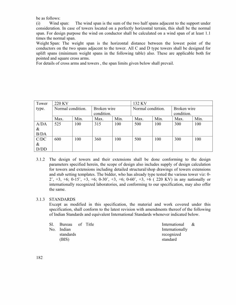
182
be as follows: (i) Wind span: The wind span is the sum of the two half spans adjacent to the support under consideration. In case of towers located on a perfectly horizontal terrain, this shall be the normal span. For design purpose the wind on conductor shall be calculated on a wind span of at least 1.1 times the normal span. Weight Span: The weight span is the horizontal distance between the lowest point of the conductors on the two spans adjacent to the tower. All C and D type towers shall be designed for uplift spans (minimum weight spans in the following table) also. These are applicable both for pointed and square cross arms. For details of cross arms and towers , the span limits given below shall prevail.
220 KV 132 KV Normal condition. Broken wire
condition. Normal condition. Broken wire
condition.
Tower type.
Max. Min. Max. Min. Max. Min. Max. Min. A/DA & B/DA
525 100 315 100 500 100 300 100
C/DC & D/DD
600 100 360 100 500 100 300 100
3.1.2 The design of towers and their extensions shall be done conforming to the design
parameters specified herein, the scope of design also includes supply of design calculation for towers and extensions including detailed structural/shop drawings of towers extensions and stub setting templates. The bidder, who has already type tested the various tower viz: 0-2˚, +3, +6; 0-15˚, +3, +6; 0-30˚, +3, +6; 0-60˚, +3, +6 ( 220 KV) in any nationally or internationally recognized laboratories, and conforming to our specification, may also offer the same.
3.1.3 STANDARDS
Except as modified in this specification, the material and work covered under this specification, shall conform to the latest revision with amendments thereof of the following of Indian Standards and equivalent International Standards whenever indicated below. Sl. No.
Bureau of Indian standards (BIS)
Title International & Internationally recognized standard
183
1. IS:209 Specification for Zinc ISO/R/752
2. IS: 2062 Structural steel (Standard quality) ISO/R/660
3. IS: 432 Mild steel and medium tensile bars and for concrete reinforcement
BS-785CSA-G-30
4. IS: 802 Code of practice for use of structural steel in overhead transmission line
Part-I/Section-I & Section2: Load and permissible stresses
Part-II: Fabrication Galvanizing Inspection and Packing
PART-III: TESTING
5. IS: 1367 Technical supply conditions for threaded fasteners
6. IS: 1893 Criteria of Earthquake resistant design structures
7. IS: 2016 Plain washers ISO/R/987
8. IS: 2551 Danger Notice Plates
9. IS: 2629 Recommended practice for hot dip galvanizing of iron and steel
10. IS: 2633 Method of testing uniformity of casting of zinc coated articles
11. IS: 3063 Single coil rectangular section spring washers for bolts, bolts, screws
DIN-127
12. IS: 5358 Hot dip galvanized coatings on fasteners
184
13. IS:5613 Part-1 & 2 Of Section-I
Code of Practices for design, installation & maintenance of overhead power line
14. IS: 6610 Specification for heavy washers for stell structures.
15. IS: 6745 Methods of determination of weight of zinc coating of zinc coated iron and steel articles.
16. IS: 12427 Hexagonal bolts for steel structures
17. INDIAN ELECTRICITY RULES 1956
18. Publication for Regulation for electrical crossing or railway tracks
3.1.4 The standards mentioned above are available from
Reference/ Name and Address from which Abbreviation the Standards are available IS BUREAU OF INDIAN STANDARDS
Manak Bhavan, 9, Bahadur Shah Zafar Marg, NEW DELHI(ORISSA)
ISO
INTERNATIONAL ORGANISATION FOR STANDARDISATION, Danish Board Standardisation, Danish Standardisening Street, Aurehoegbvej-12, DK-2900, Helleprup, DENMARK
185
CSA CANADIAN STANDARD ASSOCIATION 178, Rexdale Boulevard, Rexdale, Ontario, CANADA M9W IR
BS BRITISH STANDARDS British Standard Institution, 101, Pentonvile Road, N-19-ND-UK
DIN DEUTSCHES INSTITUTE FIIR NOR Gurggrafenstrasse 5-10 Post Fach 1107 D-1000, Berlin – 30
INDIAN ELECTRICITY RULES KITAB MAHAL 1956, REGULATION FOR Baba Kharak Singh Marg, ELECTRICAL CROSSING OF NEW DELHI – 110 001 RAILWAY TRACKS (INDIA)
3.1.5 PRINCIPAL PARAMETERS 3.1.6 Electrical System Date:
a) System voltage (kV rms) 132 b) Max. voltage (kV rms) 145 c) Lightning impulse withstand
voltage (dry & wet) (kVp) 650
d) Power frequency withstand voltage (wet) (KV rms)
275
e) Short circuit level (KA for 1 sec.
31.5
3.1.7 Line data 3.1.8 Conductor
a) Name ACSR PANTHOR
186
b) Strength & wire dia
i) Aluminium 30/3.0
ii) Steel 7/3.18
c) Conductors per Single
d) Spacing between the conductors of same phase (sub-conductor spacing) (mm)
---- ----
e) Inter-phase spacing (mm)
6.800
f) Configuration
i) Single circuit Delta
ii) Double circuit Vertical
g) Nominal Aluminium area (mm²)
270
h) Section area of Aluminium (mm²)
212.05
i) Total sectional area (mm²) 261.5
j) Calculated resistance at 200 c (Max.) ohm/km per conductor
0.14
k) Approx. calculated breaking load (KN)
127.38
l) Modulus of elasticity (GN/M²)
80
m) Co-efficient of linear exp. Per degree cent.
-6 17.8x6
n) Mass of zinc in gms/sqm
……………… 275………………
187
o) Overall diameter (mm)
21.0
p) Weight (kg/km) 974
q) Minimum ultimate tensile strength (KN)
127.38
r) Conductor tension at 32˚ C without external load
i) Initial unloaded tension
………………..35%………………
ii) Final unloaded tension
…………………25%…………….
3.1.9 Galvanized Steel Ground Wire
a) Size (no. of strands/strand dia) ………………..7/3.15……………
b) Overall diameter (mm) …………………9.45…………….
c) Standard weight (Kg/km) ………………….432…………….
d) Location of ground wire One continuous ground wire Wire to run horizontally on the top of the towers.
e) Tensile load in each ground wire (to be furnished by the Bidder)
i) At min. temp. of 5˚ C and in still air (kgs)
ii) At every day temp. of 32˚ C and still air (kgs)
iii) At 5˚ C and 2/3rd of full wind (kgs)
3.1.9.1 Towers
a) Span lengths in metres 132KV ACSR PANTHOR
188
i) Ruling design span 320 b) Wind load (kg/sqm) on conductor
c) Shielding angle with vertical
30 deg
d) Towers to be designed for heavy wind zone
V -Zone
3.1.9.2 Insulator Strings
Sl. No.
Particulars Single Suspension string
Double suspension string
Single Tension
Double Tension
1. No. of standard Discs (nos) (220kV)
1X9
2X9
1X10 2X10
2. Size of Disc (220 kV)
255X145
255X145
285
285
3. Electromechanical strength (kg) (220 kV)
9000
2X9000
11,500
2X11,500
3.0 GENERAL TECHNICAL REQUIREMENTS
4.1 Tower Design – General The employer is looking for a structurally safe design of transmission line towers to be installed on
EHV lines keeping the loadings and line parameters detailed in this specification and in compliance with IS: 802 (Part-1/Sec-1)-1995, IS: 802(Part-1/Sec-2)-1992. The Bidder may offer economical designs with rational sections or offer towers of recent design, proven in service and accepted by other reputed Central and State Sector Utilities and by OPTCL (Previously OSEB) confirming to this technical specification. The Bidder in the latter case shall forward documentation of proto type tests conducted and acceptance given by the user authorities as also performance report for such towers in service.
4.1.1 Transmission Towers 4.1.2 General Description
The towers shall be of the following types:
189
(b) Double Circuit (A, B, C & D) (c) Special Towers (River Crossing, Railway Track Crossing, Power Line Crossing
etc.) 4.1.3 The towers shall be of the self-supporting type, built up of lattice steel sections or members
and designed to carry the power conductors with necessary insulators. Ground wires and all fittings under all loading conditions. Outline diagrams of the towers required are to be furnished by the Bidder.
4.1.4 The towers shall be fully galvanized structures built up of structural mild steel sections. All
members shall be connected with bolts, nuts and spring washers. 4.1.5 Stubs and Superstructures:
(i) The stub shall mean a set of four stub angles fully galvanized from the and shall include cleats, gussets, bolts and nuts, etc. the black portion of the stub being cast in foundation footings. Stub length shall correspond to foundation depth of 3-0 metres from ground level.
(ii) Superstructure shall mean the galvanized tower assembly above the stubs which
includes structural members like angle sections, cross arms, ground wire peaks, accessories and fittings such as gusset plates, pack washers, spring, washers, ladders, step bolts, anti climbing devices and such other items which are required for completing the towers in all respect. Steel and zinc required for manufacturing these items will be arranged by the supplier.
(iii)Supply of bolts and nuts and spring washers, hangers/D-shackles for attaching
suspension strings and ‘U’ bolts for attaching ground wire suspension assemblies are included in the supply of tower.
(iv) The following provisions shall apply in connection with the procurement of steel
and zinc by the supplier.
(a) The steel used for fabrication of tower parts extensions, templates etc. shall be of mild steel of tested quality as per IS:2062 GRA.
(b) The Bidder shall take into account the fabrication wastage while quoting the
rates. The employer will not accept any liability in connection with the wastage of steel during fabrication or otherwise.
(c) The Bidder shall indicate in his offer the sizes of steel sections which are
proposed to be used by him in the design of towers.
(d) Substitutions, if any, of steel sections of the tower parts by higher sizes, due to
190
non-availability or otherwise shall be to the supplier’s account. The employer will not accept any liability on this account.
(e) The steel shall be procured exclusively from the main steel producers. However, sections not rolled by main producers, can be procured from re-rollers provided.
- Re-rolling of structural steel sections is done from billets/ingots of
tested quality. - Re-rolled sections are duly tested as per relevant standard.
(f) The zinc used for galvanizing fabricated material shall be of High Grade
Electrolytic zinc. 4.1.6 Extensions:
a) The towers shall be designed so as to be suitable for adding 3 metres, 6 metres, 9 metres extensions for maintaining adequate ground clearances without reducing the specified factor of safety in any manner.
b) The Buidder shall have to design leg extensions for all types of towers ranging from
minus 3 metres to plus 9 metres at intervals of 1.5 metres and such leg extensions shall be suitable for being fitted to a normal tower as well as a tower with extensions. This is to enable tower spotting in hilly terrain.
4.1.7 Stub setting Templates:
Stub templates shall be designed and supplied by the supplier as per requirement for all types of towers with or without extensions. Stub templates for standard towers and towers with extension shall be fined type. The stub templates shall be painted with anti-corrosive paints.
4.1.8 Fasteners: Bolts, Nuts & Washers 4.1.9 All bolts shall be of property class 5.6 and nuts of property class 5.0 IS: 1367 (Part – 3) 1991 and IS: 6639-1972 shall conform to IS: 12427, they shall be galvanized and shall have hexagonal heads and nuts, the heads being forged out of solid steel rods and shall be truly concentric and square with the shank. The shank shall be perfectly straight. 4.1.10 ully threaded bolts shall not be used, the length of bolts should be such that the threaded
portion shall not extend into the place of contact of the members. 4.1.11 ll bolts shall be threaded to take the full depth of the nut and threaded far enough to permit
firm gripping of the members, but not any further. It shall be ensured that the threaded portion of each bolt protrudes not less than 3 mm and not more than 8 mm when fully tightened. All nuts shall fit hand tight to the point where the shank of the bolt connects to the head.
191
4.1.11.1.1 Flat and tapered washers shall be provided wherever necessary. Spring washers shall be provided for insertion under all nuts. These washers shall be of electro-galvanized steel and of the positive lock type. Their thickness shall be 2.5 mm for 12 mm dia bolts, 3.5 mm for 16 mm dia bolts and 4.5 mm for 20 mm dia bolts.
4.1.11.1.2 The Bidder shall furnish bolt schedules giving thickness of members connected, size of
bolts and nuts, the length of the shank, the length of the threaded portion of bolts, sizes of bolt holes, thickness of washers and any other special details of this nature.
4.1.11.1.3 To obviate bending stress in bolts or to reduce it to a minimum, no bolt shall connect
aggregate thickness of more than three (3) times its dia. 4.1.11.1.4 The bolt positions in assembled towers shall be as per IS: 5613 (Part-I/Section-I) (Part-
II/Section-2)-1985. 4.1.11.1.5 Bolts at the joints shall be so staggered that nuts may be tightened with spanners without
fouling. 5.0 Tower Accessories 5.1 Step Bolt Ladders: These bolts shall be of property class 4.6 conform to IS: 6639-1972.
Each tower shall be provided with step bolts on one of the main legs, of not less than 16 mm diameter and 175 mm long, spaced not more than 400 mm apart and extending from about 2.5 metres above the ground level to the top of the tower. Each step bolt shall be provided with two nuts on one end to fasten the bolt security to the tower and button head at the other end to prevent the feet from slipping away. The step bolts shall be capable of withstanding a vertical load not less than 1.5 KN and shall be used as a ladder for climbing.
5.1.2 Anti-climbing devices: This shall conform to IS: 5613 (Part-I/Sec –I), 19085.
Fully galvanized barbed wire type anti-climbing device shall be provided at a height of approximately 3 metres as an anti-climbing measure. Four layers of barbed wires will be provided each inside and outside the tower in horizontal plane, spacing between the layers being 140 to 150 mm. The towers to be designed by the supplier shall have provision to fixed the barbed wire as indicated above. Thus the angle pieces with notches for accommodating barbed wire shall be designed and supplied with the towers along with provision for suitable bolt holes on leg members for fitting bolt holes on leg member for fitting the angles. The scheme of the anti-climbing device shall be submitted along with the tower drawing. Barbed wire shall be included in the scope of bidder.
5.1.3 Insulator strings and ground wire clamp attachments
(a) For the attachment of suspension insulator strings a suitable swinging hanger on
192
the tower shall be provided so as to obtain requisite clearance under extreme swinging conditions and free swinging of the string.
The hanger shall be designed to withstand an ultimate tensile strength of 11.500 kg.
(b) For ground wires at suspension towers suitable ‘U’ Bolts strong enough to withstand the full designed loads shall be provided to accommodate the hook of the ground wire suspension clamps.
(c) At tension towers, horizontal strain plates of suitable dimensions on the
underside of each power cross-arm tip and at the top ground wire peak shall be provided for taking the ‘D’ Shackles of the tension insulator strings or ground wire tension clamps, as the case may be. Full details of the attachments shall be submitted by the supplier for the employer’s approval before commencing with mass fabrication.
5.1.5 Phase Plate
Phase plate shall be of mild steel of 16 gauge vitreous enameled at back and front, circular in shape and diameter 75 mm. One set of phase plate shall be consisting of 3 plates red, yellow and blue coloured accordingly to indicate the phase of the conductor. There shall be one fixing bolt on the plate. This shall conform to IS: 5613 (Part-II/Section01) of latest edition.
5.1.6 Number Plate
The number plate shall be mild steel vitreous enameled at back and front, 200 mmx 150 mm, rectangular shape and inscribed thereon shall be the number of the tower location preceded by letter corresponding to the short name of the line and the type of towers. There shall be two fixing bolts on both end of the plates. The dimension and details of the number plate shall be as per IS: 5613 (Part-II/Section1 & Section-2), 1985.
5.1.7 Danger Plate
These shall be of mild steel vitreous enameled at back and front 250 x 200 mm rectangular shape and inscribed thereon shall be in signal red the work ‘DANGER’ with its Oriya and Hindi translation and also with the inscription of Bone and Scull and voltage of the line. There shall be two holes on the plates for fixing. This shall conform to IS: 2551 (latest edition).
5.1.8 Details to Tower Fabrication Workmanship 5.1.9 Except where hereinafter modified details of fabrications shall confirm to IS: 802 (Part-II)-
1978. 5.1.10 But splices shall generally be used such that the inside cleat angle and outside plates are
193
designed to transmit load. The inside cleat angle shall not be less than half the thickness of the connected heaviest member plus 2 mm. Lap splices may also be used for connecting members of unequal size in such a manner that the inside angle of the lap splice shall be rounded at the heel to fit the fillet of the outside angle. All splices shall develop full stress in the members connected through bolts. But as well as lap splices shall be made as above and as close to and above the main panel point as far as possible.
5.1.11 oints shall be so designed so as to avoid eccentricity. The use of gusset plates for joining
tower members shall be avoided as far as possible. However, where connections are such that the elimination of the gusset plates would result in eccentric joints then gussets plates and spacer plates may be used in conformity with modern practices. The thickness of the gusset plate, required to transmit stress, shall not be less than that of the thinnest of connected member but not less than 5 mm in any case.
The use of filler in connection shall be avoided as far as possible. The diagonal web members in tension may be connected entirely to the gusset plate where necessary so as to avoid the use of filler and it shall be connected at the point of inter-section by one or more bolts.
5.1.12 The tower structures shall be accurately fabricated to bolt together easily at site without
any strain on the bolts. 5.1.13 No angle member shall have the two leg flanges brought together by closing the angle. 5.1.14 The diameter of the hole shall be equal to the diameter of bolt plus 1.5 mm. 5.1.15 The structure shall be designed such that all parts are accessible for inspection and
cleaning. Drain holes shall be provided at all points where pockets of depressions are likely to hold water.
5.1.16 All similar parts shall be made strictly interchangeable. All steel sections before any work is done on them, shall be carefully leveled, straightened and made true to detailed drawings by methods which shall not injure the materials so that when assembled, the different matching surfaces are in close contact throughout. No rough edges shall be permitted any where in the structure. 5.1.17 Drilling and Punching
(a) Before any cutting work is started, all steel sections shall be carefully straightened and trued by pressure and not by hammering. They shall again be trued after being punched and drilled.
(b) Holes for bolts shall be drilled of punched with a jig but drilled holes are preferred.
The following maximum tolerance of accuracy of punched holes is permissible.
(i) Holes must be perfectly circular and no tolerance in this respect is permissible.
194
(ii) The maximum allowable difference in diameter of the holes on the two sides of plates or angle is 0.8 mm i.e. the allowable taper in punched holes should not exceed 0.8 mm on diameter.
(iii) Holes must be square with the plates or angles and have their walls parallel.
© All burrs left by drills or punches shall be removed completely. When the tower members be truly opposite to each other. Drilling or reaming to enlarge defective holes is not permitted.
5.1.18 Erection Mark:
Each individual member shall have an erection mark conforming to the component number given to it in the fabrication drawings. This mark shall be done with marking dies of 16 mm size before galvanizing and shall be legible after galvanising. The erection mark shall be A-BB-CC-DDD where A Employer code assigned to the supplier (Alphabet). BB Supplier’s Mark (Numerical) CC Tower type (Alphabet) DDD Number mark to be assigned by Supplier (numerical).
5.1.19.1 Galvanizing
The super structure of all towers and stubs upto 150 mm below plinth level (Top of concrete pedestal) shall be galvanized. Galvanizing of tower members and stub shall be in conformity with IS: 4759-1984 and shall be done after all fabrication work has been completed except that the nuts may be tapped or return after galvanizing. Threads of bolts and nuts after galvanizing shall have a neat fit and shall be such that they can be turned with fingers throughout the length of the threads of bolts and they shall be capable of developing the full strength of the bolts. Spring washers shall be electro-galvanized as per Grade – 4 of IS: 1573 – 1986. Galvanizing for fasteners shall conform to IS: 1367 (Part-XIII) – 1978.
5.1.19.2 Quantities and Weights 5.1.20 The quantities stated in Annexure – I are only provisional. Final quantities will be informed
by the employer to the supplier on completion of detailed survey. However, bids will be evaluated based on quantities indicated in the Annexure – I.
5.1.21 The employer reserves the right to order for the final quantities at the rates quoted in the
bid, which shall be valid throughout the pendency of the contract.
195
5.1.21.1.1 The unit weight of each type of tower stubs, super structure and extension be furnished
by the Bidder. The weight of tower shall mean the weight of tower calculated by using the black section(ungalvanized) weight of steel members including stubs, of the sizes indicated in the approved fabrication drawings and bills of materials, without taking into consideration the reduction in weights due to holes, notches, cuts, etc. but taking into consideration the weight of special fittings.
5.1.21.2 Tower designs Superstructure 5.1.21.2.1 Wind Pressure
The wind pressure on towers, power conductors and earth wire shall be as per IS: 802 (Part-I/Sec-I) – 1995. 280
5.1.21.2.2 Design Temperatures
The following temperature range for the power conductor and ground wires shall be adopted for the line design confirming to IS: 802 (Part –I/Sec – I) – 1995. i) Minimum temperature 50˚C. ii) Every day temperature 32˚C iii) Maximum temperature of:
a) Conductor 75˚C for ACSR Zebra/Panther b) Ground wire 53˚C exposed to Sun.
5.1.21.2.3 Factors of Safety & Span details
a) Factory of safety. The factor of safety based on crippling strength of struts and elastic limit of tension members shall not be less than 2(two) under normal condition and 1.5 (one and a half) under broken wire conditions for all the members of the towers and their cross arms.
b) Normal Span
The normal span of the line shall be 250 metres for 132 kV. c) Wind and weight spans
196
The wind and weight spans to be adopt in the design of the structures shall be as follows: i) Wind Span
The wind span is the sum of the two half spans adjacent to the support under consideration. In case of towers located on an perfectly horizontal terrain, this shall be the normal span. For design purposes the wind on conductor shall be calculated on at least 1.1 times the normal.
ii) Weight Span The weight span is the horizontal distance between the lowest point of the conductors on the two spans adjacent to the tower. All C and D type towers shall be designed for uplift spans (minimum) weight spans in the following table also. These are applicable both for pointed and square cross arms. For details of cross arms and towers, the span limits given below shall prevail.
5.1.21.2.4 Conductor and Ground wire Configuration
For single circuit towers the three phases shall be Delta formation. One number of ACSR conductor shall be used for each phase. One galvanized steel wire shall be used as ground wire. The ground wire shall be continuous and shall be provided above the conductors at suitable elevation to offer effective shielding and safe clearances. For double circuit towers the phases shall be in vertical formation with phase to phase horizontal spacing of not less than 8.4 meters and vertical 4.9 meters for 132kV.
5.1.21.2.5 Loads on Towers
i) Transverse Loads:
Transverse load due to wind on towers conductors and under broken wire earthwire shall be calculated in accordance with IS: 802(Part-I/Sec-I)-1995.
ii) Longitudinal Loads due to wind on towers conductors and shield shall be calculated
as per IS: 802 (Part-I/Sec-I)-1995. iii) Vertical Loads:
The vertical load due to conductors and ground wire shall also include 150 kg. As weight of a Lineman with tools. These loads are in addition to the vertical loads due to insulator fittings and the dead weight of the structure. The weight of a
197
Lineman with tool should not be considered in minimum vertical load calculation. An additional erection load of 3.5 KN shall also be considered for the design of the tower. The stringing procedure shall ensure that the above vertical loads are not exceeded.
iv) Broken Wire condition
a) Suspension Tower Type A/PA
Breaking of any one power conductor in one phase only, resulting in instanceous unbalance tension of 50% of conductor tension at 32˚C without wind or breaking of one earthwire resulting in an unbalance tension equal to the maximum tension of the ground wire whichever is more stringent is to be considered for design along with appropriate impact factor.
b) Tower Type B & C
Breakage of two phases on the same side and on the same span or breakage of any one phase and any one ground wire on the same span whichever combination is more stringent along with appropriate impact factor for a particular member.
c) Tower Type D/DD
Breakage of all the three phases on the same side and on the same span or breakage of two phases and any one ground wire on the same span, whichever combination is more stringent along with appropriate impact factor for a particular member. Cross arms for angle tower shall be of equal length for both sides.
v) Design Load
Employer’s requirement for design longitudinal and transverse loads shall confirm to IS: 802(Part-I/Sec-I)-1995. The Bidder shall furnish the details of design loads proposed to be adopted in the tower design in accordance with this specification. The design criteria and other special requirements as stipulated for special towers shall be applicable for river crossing/special towers.
5.1.21.2.6 Tower Steel Sections:
i) Steel sections of tested quality in conformity with IS: 2062 GRA are to be used in towers, extensions and stub setting templates. No individual members shall be longer than 6000 mm.
For designing of towers only rationalized steel sections shall be used. During
198
execution of the project, if any particular section is not available, the same shall be substituted by higher section at no extra cost. However, design approval for such substitution shall be obtained from the employer.
ii) Thickness of Members The minimum thickness of angle sections used ion the design of towers, shall be kept not less than the following values: a) Main corner leg members excluding the ground wire peak and main cross arm 6
mm. b) For all other main members 5 mm. c) Redundant members 4 mm.
iii) Bolt Arrangement
The minimum bolt spacing and rolled edge distance and sheared edge distances of sections from the centers of the bolt holes shall be provided as furnished in Table-1. Dia of Bolts (mm)
Hole Dia (mm)
Min. bolt Spacing (mm)
Min. rolled Distance (mm)
Min. Sheared Edge distance (mm)
12 13.5 30 16 19
16 17.5 40 20 23
20 21.5 50 25 27
Bolts sizes mentioned above shall only be used. The minimum width of flanges without bolt holes shall be 30 mm. For the purpose of calculating stress and bearing stress for bolts refer clause 14.4 and 14.5 of IS: 802 (Part-I/Sec-2)-1992.
iv) Allowable Stress:
Structural steel angle section manufactured according to the latest ISL: 808(Part-V & VI) and tested according to the latest edition of IS:2062 and having its yield strength not less than 255 N/mm. sq. shall be used in the fabrication of tower members.
v) Axial Stress in tension:
199
The estimated tensile stress in various members multiplied by the appropriate factors of safety shall not exceed the value given by the formula specified in Clause 9.2.1 of IS:802(Part-I/Sec-2)-1992.
vi) Axial Stress in Compression The estimated compressive stress in various members multiplied by the appropriate
factors of safety shall not exceed the value given by the formula specified in Clause 9.2.1 of IS:802(Part-I/Sec-2)-1992.
vii) Slenderness ratio: Slenderness ratio for members shall be computed in accordance with IS:802(Part-
I/Sec-2)-1992. Slenderness ratio for compression and tension members shall not exceed the values specified therein. The following maximum limits of the slenderness ratio shall be adopted i.e. the ratio of unsupported length of the section in any place to the appropriate radius of gyration.
a) For main corner leg member includi9ng the corner
members of earth wire peak and the lower corner members of the arms…
150
b)
For other members having calculated stresses….
200
c) For redundant members…. 250
d) For members having tensile stress only…. 375
viii) Erection Stress Where erection stresses combined with other permissible co-existent stresses could
produce a working stress in any member appreciably above the specified working stress, then additional materials shall be added to the member or such other provision made so as to bring the working stress within the specified limit. For the purpose of this clause the specified working stress shall be the ultimate stress divided by the factor of safety of 2.0.
ix) Design calculation and Drawings The following design calculations and drawings are required to be furnished to the
employer.
a) Along with the Bid:
200
Detailed design calculations and drawing for each type of tower. b) On award of Contract The supplier shall submit design of tower extension, stub templates and
loading/rigging arrangement of tower testing to enable the employer to make preliminary check regarding structural stability of tower tests.
Upon successful testing of tower and subsequent approval of designs, drawings
and bill of materials, the supplier shall furnish photostat copies of the following in 6(six) copies to the employer for necessary distribution along with one copy of reproducible print.
a) Detailed design calculations along with drawings of towers and
foundations. b) Detailed structural drawings indicating section size, length of member.
Sizes of plate along with hole to hole distances, joint details etc.
c) Bill of materials indicating cutting and bending details against each member.
d) Shop drawings showing all details relevant to fabrication.
e) All drawings for the tower accessories.
The supplier is required to submit four copies of the drawings with Photostat copies mentioned above for approval by the employer while submitting the designs, structural drawings. Bill of materials and any other drawings pertaining to the subject transmission line. The supplier shall clearly indicate in each drawing the project code number, if any, specification no.;, name of transmission line, letter reference no. and date on which the submissions are made. The said procedure is to be followed while submitting the distribution copies.
5.1.21.2.7 Statutory Electrical Clearances:
i) Ground Clearances: The minimum ground clearance from the bottom conductor shall not be less than
7.00 metres for 220 kV at the maximum sag conditions i.e. at maximum temperature and in still air. However, to achieve the above clearance the height of the tower shall be increased in the following manner:
a) An allowance of 4% of the maximum sag shall be provided to account for errors
in stringing.
201
b) Conductor creep shall be compensated by over tensioning the conductor for a
temperature of 26˚C lower than the stringing temperature. In case of rail track crossings the minimum height above rail level of the lowest
portion of any conductor under conditions of maximum sag, in accordance with the regulations for Electrical Crossing of Railway Tracks are given in Table – 5.
TABLE – 5
Type of work Inside stn.
Limits(mm) Outside stn. Limits(mm)
a) For unelectrified track and tracks electrified on 1500 V.DC
i) For metre/narrow gauge 10,00017,600
ii) For broad gauge 11,200 8,800
b) Tracks electrified on 25 kV AC for metre, narrow and broad gauge
15,300 13,300
Minimum clearance between the subject power line and any other power line
crossing shall not be less than 7000 mm.
ii) Live Metal Clearance:
The minimum live metal clearance to be provided between the live parts and steel work of superstructure shall be as given in IS:5613 (Part-2/Sec-I).
The Bidder may adopt separate cross arm design and length for ‘D’ type towers
under dead end conditions provided adequate live metal clearance is available with at least 15˚ angle and also provided that all the other specified conditions of this specifications are fulfilled. In case pilot insulator strings are proposed to be used, the angle of swing to be considered shall be minimum of 15˚.
In computing live metal clearances, the dimensions of suspension and tension string
shall be taken as given in drawings attached herewith. The design of the towers shall be such that it should satisfy all the above conditions when clearances are measured from any live point of the insulator strings.
iii) Angle Shielding The angle shielding, defined as the angle formed by the line joining the center lines
202
of the ground wire and outer conductor in still air, at tower supports, to the vertical line through the center line of the ground wire shall not be more than 30˚. The drop of the ground wire clamp which is employer supplied item should be considered while calculating the minimum angle of protection. For estimating the minimum angle of protection the drop of ground wire suspension clamp along with U-bolt may be taken as 150 mm.
iv) Mid Span Clearance The minimum vertical span clearance between any of the earthwire and the nearest
power conductor under all temperatures and in still air condition in the normal ruling span shall be 8.10 metres for 220 kV. Further the tensions of the earthwires and power conductors, shall be so co-ordinated that the sag of earthwires shall be at least 10% less than that of the power conductors under all temperatures and loading conditions.
4.3.5.10 Packing
Angle sections shall be wire bundled, cleat angles, gusset plates, blackets, filler plates, hanger and similar other loose items shall be netted and bolted together in multiples or securely wired together through holes. Bolts, nuts, washers and other attachments shall be packed in double gunny bags, accurately tagged, in accordance with the contents. The packings shall be properly done to avoid losses/damages during transit. Each bundle or package shall be appropriately marked.
5.1.21.3 Special Towers:
i) Special towers are to be used for major river crossing requiring very long spans. These towers shall form part of the Bidder’s scope.
Unit rates for design, fabrication, galvanizing, testing and supply for such towers
shall be quoted in the appropriate schedule of Volume IB. Anchoring of major river crossing towers, shall be with ‘D’ or DD type towers. All the requirements as meant for standard towers shall apply for such special towers
except those noted in the following clauses. ii) Shielding Angle:
The shielding angle shall not be greater than 30˚. iii) Clearances: The minimum clearance of lowest point of power conductor from the highest flood
203
level in navigable rivers for crossing towers shall be obtained from the navigation authority.
The minimum electrical clearances between live parts and tower body and cross arm
member shall be the same as for normal towers. iv) Stub Location: The approximate height of foundation on which stub for river cross towers are to be
set, over the highest flood level of the river shall be fixed only after employer’s approval.
v) Angle of Deviation The minimum angle of deviation to be considered for special towers is 2˚ and all live
material clearances are to be computed considering double suspension insulator strings as per drawing enclosed.
vi) Factors of Safety: Towers:
The minimum factors of safety for towers shall be:
a) Under normal conditions 2.0 b) Under broken wire conditions 1.;5
vii) Conductor and Earth wire: The minimum factor of safety for conductors and ground wire shall be 2.5 maximum
tension corresponding to 2/3rd full wind pressure at minimum temperature or full wind pressure at the mean annual temperature such that the initial unloaded tension at the mean annual temperature do not exceed 30% of the ultimate strength of conductor and ground wire respectively.
viii) Wind Loads:
a) The procedure for wind load calculation on conductor and ground wire shall be the same as for normal structures.
b) The wind pressure values on tower shall be based on IS:802(Part-I/Sec-I)-1995.
ix) Longitudinal Loads:
a) The longitudinal loads due to power conductors and earth wires for suspension towers shall be nil under normal conditions and 100% of the maximum tension of bundled conductors or earth wire under broken wire conditions.
204
b) Under normal conditions, unbalanced longitudinal pull due to difference in
tension in ruling span for river crossing towers on one side and span of the line on the other wise shall also be considered for the design of anchor towers.
5.1.22 TESTS 5.1.23 General
a) All standard tests including quality control tests in accordance with IS:802(Part-III)-1978 shall be carried out.
b) A galvanized tower of each type complete with 6 metres extension shall be subjected
to design and destruction test. The tower shall be tested with nuts and bolts of the same make and type which are proposed to be used on the line. The supplier shall submit to the employer for approval, a detailed programme and proposal for testing the towers showing the method of carrying out the tests and the manner of applying the loads. The supplier on receipt of such approval shall intimate the employer about carrying out of the tests at least 30 days in advance of the scheduled date of tests during which time the employer will arrange to depute his representatives to witness the tests. Six copies of the test reports thereof shall be submitted to the employer for approval.
c) In case of premature failure, the tower shall be retested and steel already used in the earlier test shall not be used again. The supplier shall provide facilities to the employer for inspection of materials during manufacturing stage and also during testing of the same.
d) No part of any tower subject to test shall be allowed to be used in the work. The prices
to be quoted for such type tests shall be after allowing rebate for the scrap value of the tested tower which is to be retained by the supplier
e) The supplier shall ensure that the specification of materials and workmanship of all
towers actually supplied conform strictly to the towers which have successfully undergone the tests. In case any deviation is detected the supplier shall replace such defective towers free of cost of the employer. All expenditure incurred in erection, to and fro transportation, any other expenditure or losses incurred on this account shall be fully borne by the supplier.; No extension in delivery time shall be allowed on this account. The employer, however, reserves the right to waive off the testing of the towers, provided the supplier had earlier successfully tested, erected and commissioned similar towers and certificates for such tests carried out earlier are furnished duly certified by the employer and are found acceptable.
f) Each type of tower to be tested shall be a full scale prototype galvanized tower and
shall be erected vertically on rigid foundation with the stub protruding above ground level as provided in the design/drawing between ground level and concrete level.
g) The suspension tower to be tested shall be with hanger and ‘U’ Bolt as per approved
205
design/drawings. The tension tower to be tested shall similarly be with the strain plate as per approved design/drawings.
h) In case of any premature failure even during waiting period, the tower shall be retested
with rectified members. However, if the failures are major in nature and considerable portion of tower is to be re-erected then in such cases all the tests which have been carried out earlier are to be reconducted to the entire satisfaction of the employer.
i) The sequence of testing shall be at the discretion of the employer.
5.1.23.2 Test for Galvanization
Galvanization of the members of the tower shall withstand tests as per IS:2633. 5.1.24 INSPECTION 5.1.24.2 The supplier shall keep the employer informed well in advance of the commencement of
manufacture, progress of manufacture thereof and fabrication of various tower parts at various stages. So that arrangements could be made for inspection by the employer.
5.1.24.3 The acceptance of any batch of items shall in no way relieve the supplier of any his responsibilities for meeting all the requirements and intent of this specification and shall not prevent subsequent rejection if any item of that batch is later found defective.
5.1.24.4 The employer or his authorized representatives shall have free access at all reasonable
time to all parts of the supplier’s works connected with the fabrication of the material covered under the contract for satisfying themselves that the fabrication is being done in accordance with the provisions of this specification.
5.1.24.5 Unless specified otherwise, inspection shall be made at the place of manufacture prior to
dispatch and shall be conducted so as not to interfere unnecessarily with the operation of the work.
5.1.24.6 Should any member of the structure be found not to comply with the approved design, it
shall be liable for rejection. No member once rejected shall be resubmitted for inspection except in cases where the employer or his authorized representative considers that the defects can be rectified.
5.1.24.7 Defects which occur during fabrication shall be made good with the consent of and
according to the procedure to be laid down by the employer. 5.1.24.8 All gauges and templates necessary to satisfy the employer for conducting tests shall be
made available at the test site by the supplier. 5.1.24.9 The correct grade and quality of steel shall be used by the supplier. To ascertain the
quality of steel the employer may at his discretion get the material tested at an approved laboratory.
206
5.1.25 SCHEDULE OF REQUIREMENTS 5.1.25.2 The schedule of requirements of different types of towers is indicated in Volume-III. The
quantities indicated therein are tentative and based on preliminary survey conducted by the employer. The exact quantity will be informed to the supplier on completion of detailed survey.
5.1.25.3 The time frame for executing the work is also indicated in this schedule. The supplier has
to match the supply and delivery of stubs, tower-parts etc. to complete the work within the time schedule desired by the employer.
5.1.25.4 The supplier shall, as far as possible, dispatch the tower material as completed towers in
order to enable erection of complete tower structures at site. Payment for the initial dispatches, to the extent of 30% of the total ordered quantity will be released on the basis of weight (i.e. Metric tones of steel supplied). Beyond this limit, however, payment will be released only for material supplied to complete towers.
5.1.26 SCUEDUALE OF PRICES 5.1.26.2 The prices for supply of materials shall be furnished in the relevant schedule in the
manner specified in Volume-III. 5.1.27 GENERAL TECHNICAL REQUIREMENTS
Design details - foundation Line voltage - 220 kV No. of circuits - Two Particulars a) Properties of soil for bidding purpose only
Sl. No.
Details Soft Loose
Mud Hard Soil
Soft Rock
Hard Rock
1. Angle of repose of soil(in degree)
30 15 0 0 0
2. Ultimate bearing strength of earth (T/M²)
10 5 20.0 50.0 125.0
b) Properties of concrete
Weight of foundation concrete 1:2:4 mix for design purpose shall be taken as 2400 kg/cu.m in dry location.
c) Factor of safety for foundation against over turning due to up-lift and thrust.
207
i) Normal condition 2.2 ii) Broken wire condition 1.65
d) Concrete Mixture i) pad 1:4:8 ii) Pyramid or stepped part of foundation 1:1:5:3 iii) Chimney 1:1:5:3
e) Minimum thickness of chimney 300 m f) Minimum thickness of concrete over stub
Dry soil 100 mm Wet & WBC 150 mm
g) Minimum length of stub 2000 mm
in concrete.
h) Distance above ground level of 450 mm Tower stub and super structure
5.1.28 .Foundation General Description 5.1.29 Design, construction and other relevant drawings shall be furnished by the tower designer for all types of towers (including special towers) for different kinds of soil as detailed below. According to the locations foundations for towers shall be normally of the following types:
a) Soft/Loose Soil b) Mud c) Hard/Dense soil d) Hard/Disintegrated rock
5.1.30 For rock foundations the holes in rocks shall be made in an approved manner so as to eliminate the possibility of serious cracking of the rock. The concrete block shall be properly secured to rock base by adequate no. of anchor bolts and further secured by concrete lodge section by the sides.
PILE FOUNDATION-PB AND UR+6 TOWERES
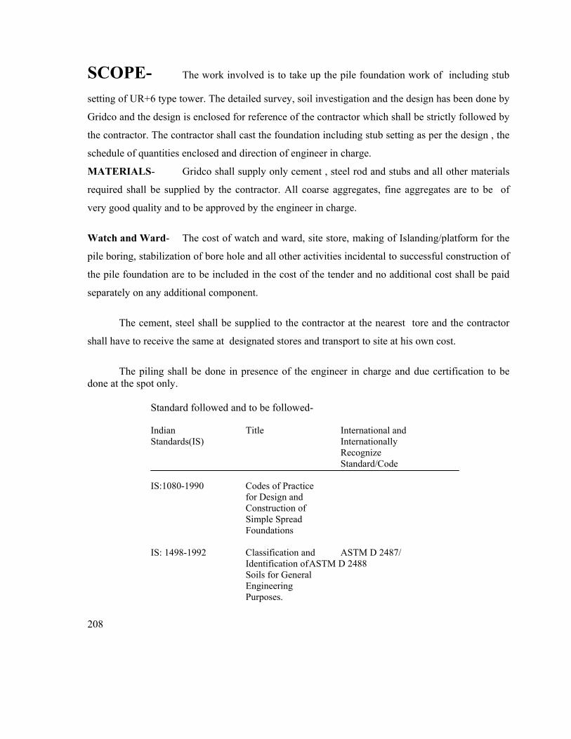
208
SCOPE- The work involved is to take up the pile foundation work of including stub
setting of UR+6 type tower. The detailed survey, soil investigation and the design has been done by
Gridco and the design is enclosed for reference of the contractor which shall be strictly followed by
the contractor. The contractor shall cast the foundation including stub setting as per the design , the
schedule of quantities enclosed and direction of engineer in charge.
MATERIALS- Gridco shall supply only cement , steel rod and stubs and all other materials
required shall be supplied by the contractor. All coarse aggregates, fine aggregates are to be of
very good quality and to be approved by the engineer in charge.
Watch and Ward- The cost of watch and ward, site store, making of Islanding/platform for the
pile boring, stabilization of bore hole and all other activities incidental to successful construction of
the pile foundation are to be included in the cost of the tender and no additional cost shall be paid
separately on any additional component.
The cement, steel shall be supplied to the contractor at the nearest tore and the contractor
shall have to receive the same at designated stores and transport to site at his own cost.
The piling shall be done in presence of the engineer in charge and due certification to be
done at the spot only. Standard followed and to be followed-
Indian Title International and Standards(IS) Internationally
Recognize Standard/Code
IS:1080-1990 Codes of Practice for Design and Construction of Simple Spread Foundations IS: 1498-1992 Classification and ASTM D 2487/ Identification of ASTM D 2488 Soils for General Engineering Purposes.
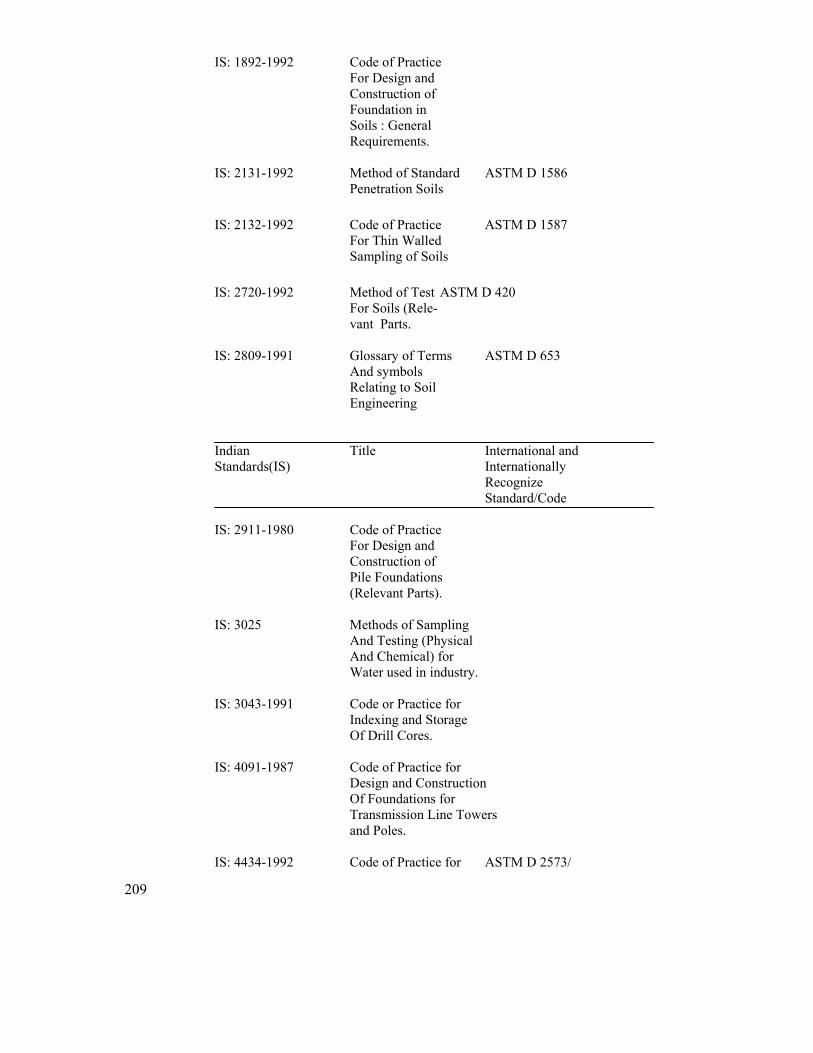
209
IS: 1892-1992 Code of Practice For Design and Construction of Foundation in Soils : General Requirements. IS: 2131-1992 Method of Standard ASTM D 1586 Penetration Soils IS: 2132-1992 Code of Practice ASTM D 1587 For Thin Walled Sampling of Soils IS: 2720-1992 Method of Test ASTM D 420 For Soils (Rele- vant Parts. IS: 2809-1991 Glossary of Terms ASTM D 653 And symbols Relating to Soil Engineering Indian Title International and Standards(IS) Internationally
Recognize Standard/Code
IS: 2911-1980 Code of Practice For Design and Construction of Pile Foundations (Relevant Parts). IS: 3025 Methods of Sampling And Testing (Physical And Chemical) for Water used in industry. IS: 3043-1991 Code or Practice for Indexing and Storage Of Drill Cores. IS: 4091-1987 Code of Practice for Design and Construction Of Foundations for Transmission Line Towers and Poles. IS: 4434-1992 Code of Practice for ASTM D 2573/
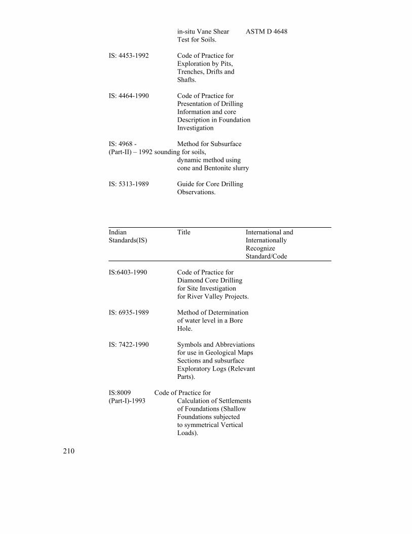
210
in-situ Vane Shear ASTM D 4648 Test for Soils. IS: 4453-1992 Code of Practice for Exploration by Pits, Trenches, Drifts and Shafts. IS: 4464-1990 Code of Practice for Presentation of Drilling Information and core Description in Foundation Investigation IS: 4968 - Method for Subsurface (Part-II) – 1992 sounding for soils, dynamic method using cone and Bentonite slurry IS: 5313-1989 Guide for Core Drilling Observations. Indian Title International and Standards(IS) Internationally
Recognize Standard/Code
IS:6403-1990 Code of Practice for
Diamond Core Drilling for Site Investigation for River Valley Projects. IS: 6935-1989 Method of Determination of water level in a Bore
Hole. IS: 7422-1990 Symbols and Abbreviations for use in Geological Maps Sections and subsurface Exploratory Logs (Relevant Parts). IS:8009 Code of Practice for (Part-I)-1993 Calculation of Settlements of Foundations (Shallow Foundations subjected to symmetrical Vertical Loads).
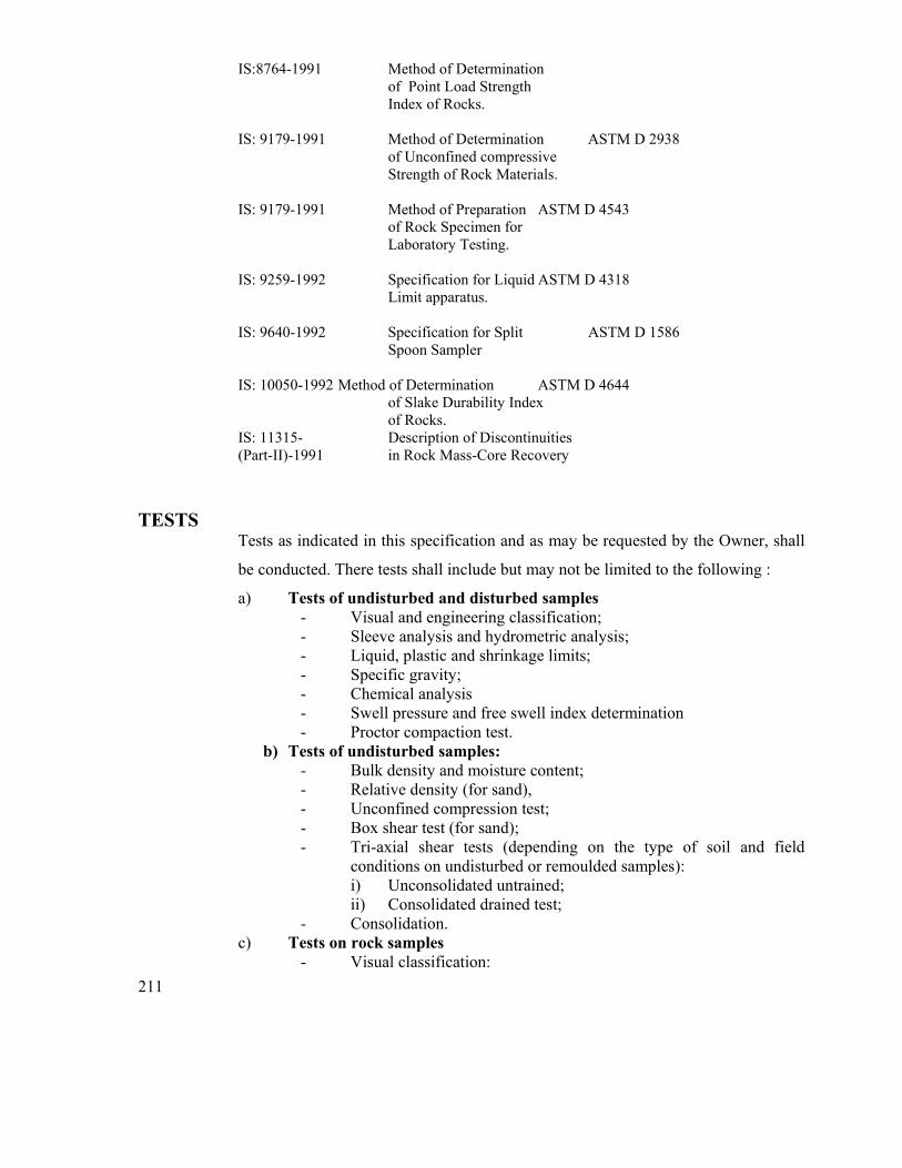
211
IS:8764-1991 Method of Determination of Point Load Strength Index of Rocks. IS: 9179-1991 Method of Determination ASTM D 2938 of Unconfined compressive Strength of Rock Materials. IS: 9179-1991 Method of Preparation ASTM D 4543 of Rock Specimen for Laboratory Testing. IS: 9259-1992 Specification for Liquid ASTM D 4318 Limit apparatus. IS: 9640-1992 Specification for Split ASTM D 1586 Spoon Sampler IS: 10050-1992 Method of Determination ASTM D 4644 of Slake Durability Index of Rocks. IS: 11315- Description of Discontinuities (Part-II)-1991 in Rock Mass-Core Recovery
TESTS
Tests as indicated in this specification and as may be requested by the Owner, shall
be conducted. There tests shall include but may not be limited to the following :
a) Tests of undisturbed and disturbed samples - Visual and engineering classification; - Sleeve analysis and hydrometric analysis; - Liquid, plastic and shrinkage limits; - Specific gravity; - Chemical analysis - Swell pressure and free swell index determination - Proctor compaction test.
b) Tests of undisturbed samples: - Bulk density and moisture content; - Relative density (for sand), - Unconfined compression test; - Box shear test (for sand); - Tri-axial shear tests (depending on the type of soil and field
conditions on undisturbed or remoulded samples): i) Unconsolidated untrained; ii) Consolidated drained test;
- Consolidation. c) Tests on rock samples
- Visual classification:
212
- Moisture content, porosity and density: - Specific gravity; - Hardness - Stake durability; - Unconfined compression test (both saturated and at in-situ water
content; - Point load strength index; - Deformability test (both saturated and dry samples)
213
SCHEDULE OF QUANTITIES

214
PACKAGE-1
215
SCHEDULE OF QUANTITIES FOR
DIVERSION OF 132 KV LINES
PRICE SCHEDULE
Since PV clause shall be applicable to most of the items, firms
must quote the Exworks price of the materials basing on
which PV shall be calculated
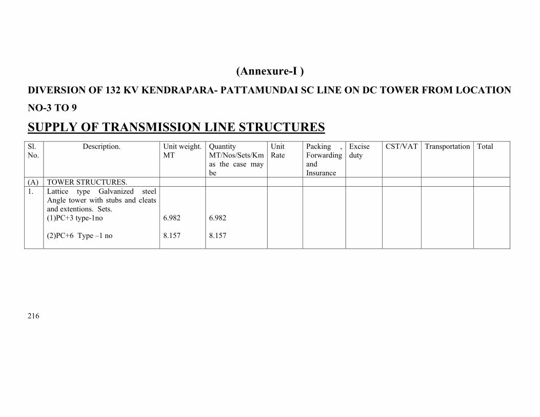
216
(Annexure-I ) DIVERSION OF 132 KV KENDRAPARA- PATTAMUNDAI SC LINE ON DC TOWER FROM LOCATION
NO-3 TO 9 SUPPLY OF TRANSMISSION LINE STRUCTURES
Sl. No.
Description. Unit weight. MT
Quantity MT/Nos/Sets/Km as the case may be
Unit Rate
Packing , Forwarding and Insurance
Excise duty
CST/VAT Transportation Total
(A) TOWER STRUCTURES. 1. Lattice type Galvanized steel
Angle tower with stubs and cleats and extentions. Sets. (1)PC+3 type-1no
(2)PC+6 Type –1 no
6.982 8.157
6.982 8.157
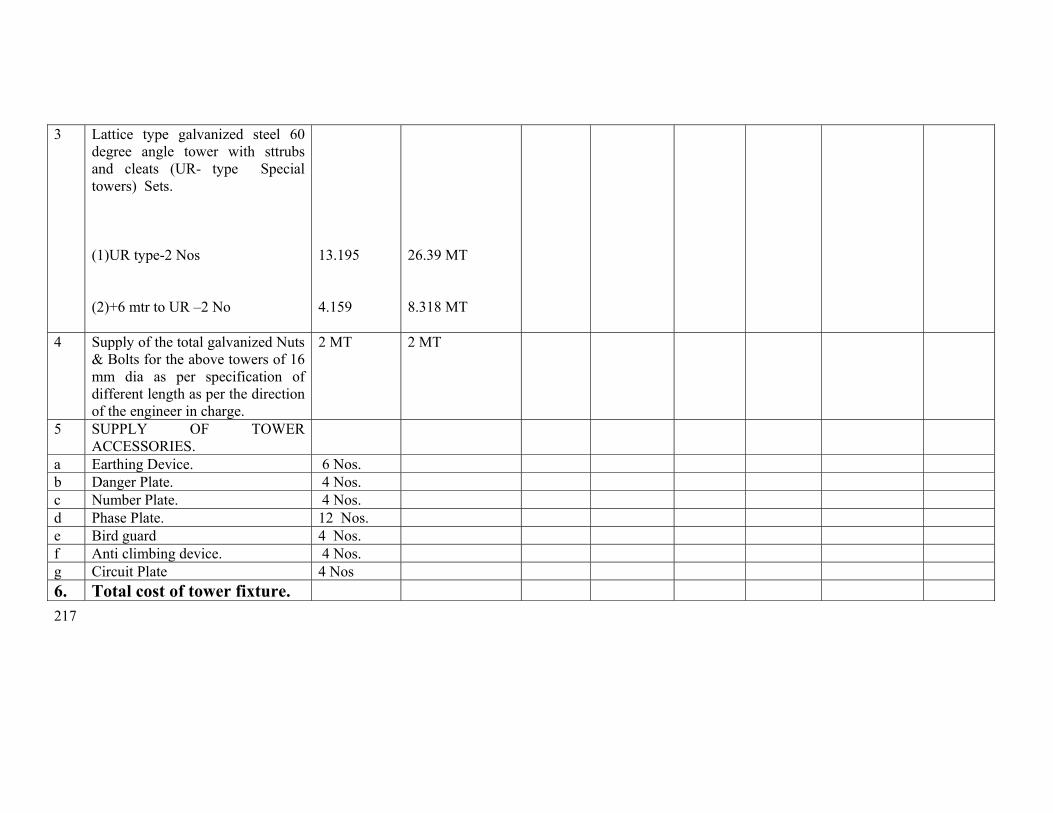
217
3 Lattice type galvanized steel 60 degree angle tower with sttrubs and cleats (UR- type Special towers) Sets.
(1)UR type-2 Nos (2)+6 mtr to UR –2 No
13.195 4.159
26.39 MT 8.318 MT
4 Supply of the total galvanized Nuts & Bolts for the above towers of 16 mm dia as per specification of different length as per the direction of the engineer in charge.
2 MT 2 MT
5 SUPPLY OF TOWER ACCESSORIES.
a Earthing Device. 6 Nos. b Danger Plate. 4 Nos. c Number Plate. 4 Nos. d Phase Plate. 12 Nos. e Bird guard 4 Nos. f Anti climbing device. 4 Nos. g Circuit Plate 4 Nos 6. Total cost of tower fixture.
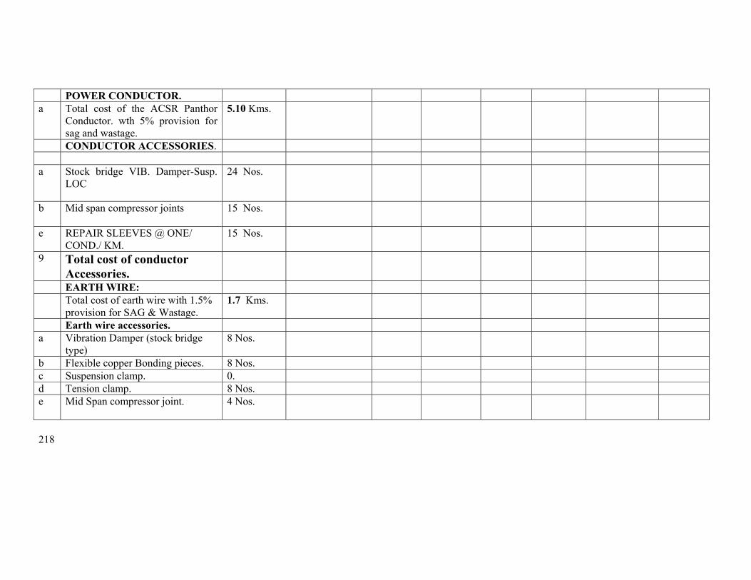
218
POWER CONDUCTOR. a Total cost of the ACSR Panthor
Conductor. wth 5% provision for sag and wastage.
5.10 Kms.
CONDUCTOR ACCESSORIES. a Stock bridge VIB. Damper-Susp.
LOC 24 Nos.
b Mid span compressor joints
15 Nos.
e REPAIR SLEEVES @ ONE/ COND./ KM.
15 Nos.
9 Total cost of conductor Accessories.
EARTH WIRE: Total cost of earth wire with 1.5%
provision for SAG & Wastage. 1.7 Kms.
Earth wire accessories. a Vibration Damper (stock bridge
type) 8 Nos.
b Flexible copper Bonding pieces. 8 Nos. c Suspension clamp. 0. d Tension clamp. 8 Nos. e Mid Span compressor joint. 4 Nos.
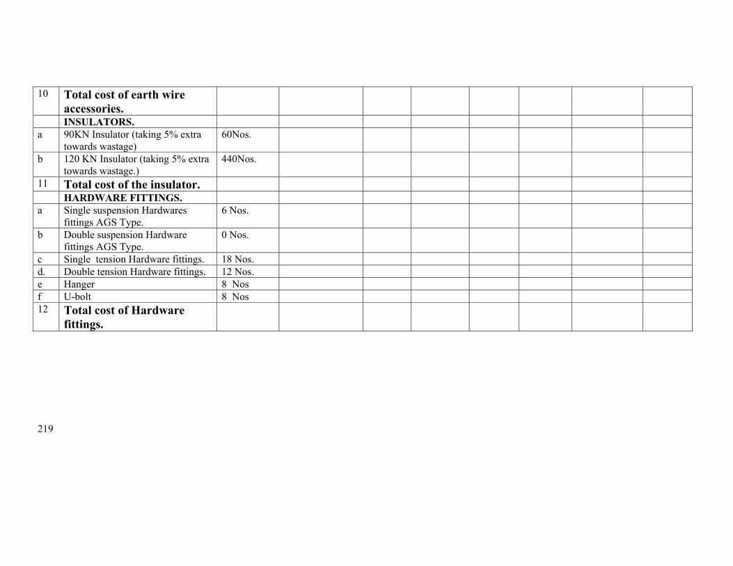
219
10 Total cost of earth wire accessories.
INSULATORS. a 90KN Insulator (taking 5% extra
towards wastage) 60Nos.
b 120 KN Insulator (taking 5% extra towards wastage.)
440Nos.
11 Total cost of the insulator. HARDWARE FITTINGS. a Single suspension Hardwares
fittings AGS Type. 6 Nos.
b Double suspension Hardware fittings AGS Type.
0 Nos.
c Single tension Hardware fittings. 18 Nos. d. Double tension Hardware fittings. 12 Nos. e Hanger 8 Nos f U-bolt 8 Nos 12 Total cost of Hardware
fittings.
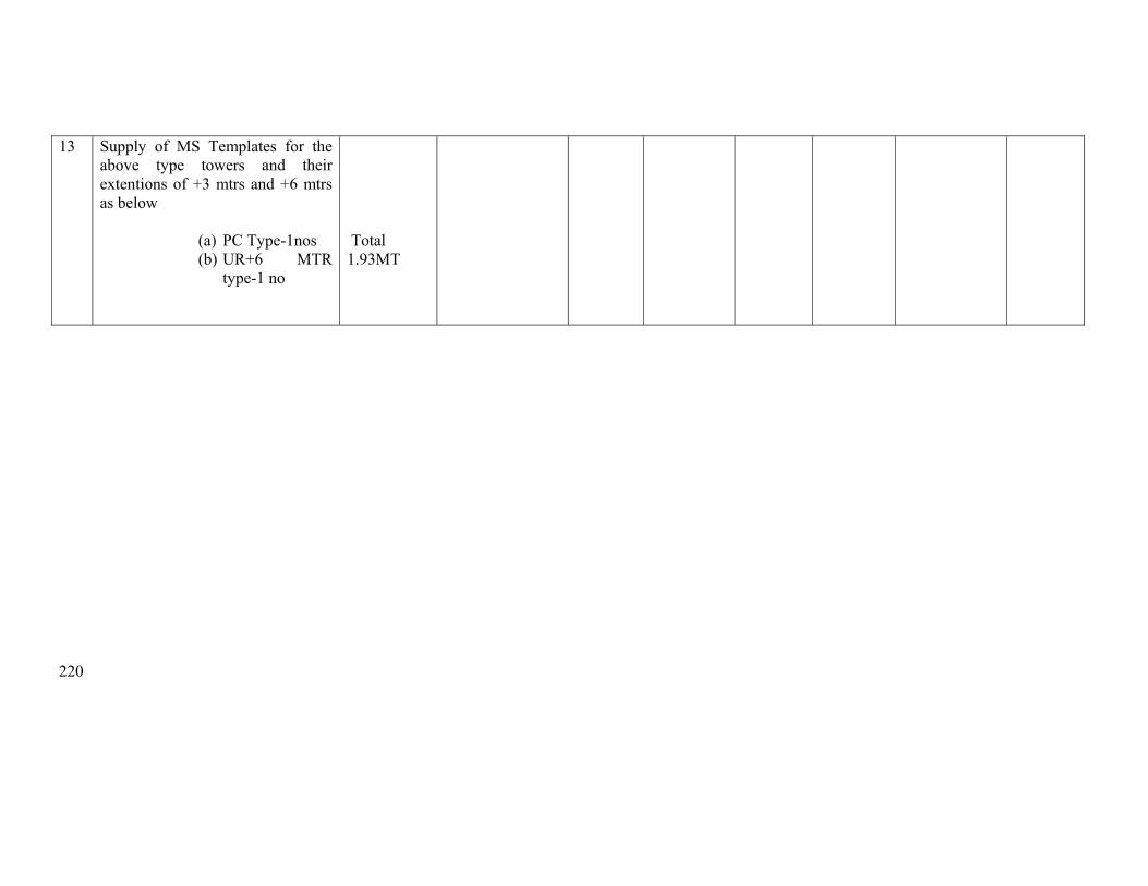
220
13 Supply of MS Templates for the above type towers and their extentions of +3 mtrs and +6 mtrs as below
(a) PC Type-1nos (b) UR+6 MTR
type-1 no
Total 1.93MT
221
Erection Schedule for Loc-3 to 9
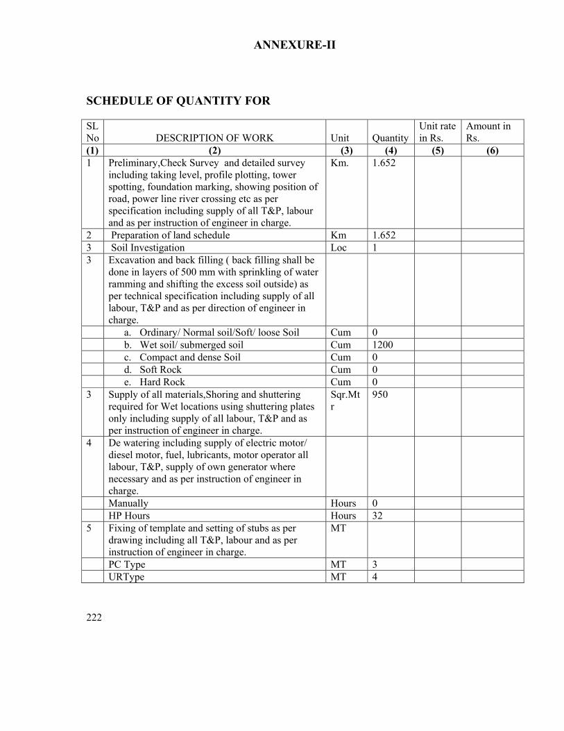
222
ANNEXURE-II SCHEDULE OF QUANTITY FOR SL No
DESCRIPTION OF WORK
Unit
Quantity
Unit rate in Rs.
Amount in Rs.
(1) (2) (3) (4) (5) (6) 1 Preliminary,Check Survey and detailed survey
including taking level, profile plotting, tower spotting, foundation marking, showing position of road, power line river crossing etc as per specification including supply of all T&P, labour and as per instruction of engineer in charge.
Km. 1.652
2 Preparation of land schedule Km 1.652 3 Soil Investigation Loc 1 3 Excavation and back filling ( back filling shall be
done in layers of 500 mm with sprinkling of water ramming and shifting the excess soil outside) as per technical specification including supply of all labour, T&P and as per direction of engineer in charge.
a. Ordinary/ Normal soil/Soft/ loose Soil Cum 0 b. Wet soil/ submerged soil Cum 1200 c. Compact and dense Soil Cum 0 d. Soft Rock Cum 0 e. Hard Rock Cum 0 3 Supply of all materials,Shoring and shuttering
required for Wet locations using shuttering plates only including supply of all labour, T&P and as per instruction of engineer in charge.
Sqr.Mtr
950
4 De watering including supply of electric motor/ diesel motor, fuel, lubricants, motor operator all labour, T&P, supply of own generator where necessary and as per instruction of engineer in charge.
Manually Hours 0 HP Hours Hours 32 5 Fixing of template and setting of stubs as per
drawing including all T&P, labour and as per instruction of engineer in charge.
MT
PC Type MT 3 URType MT 4
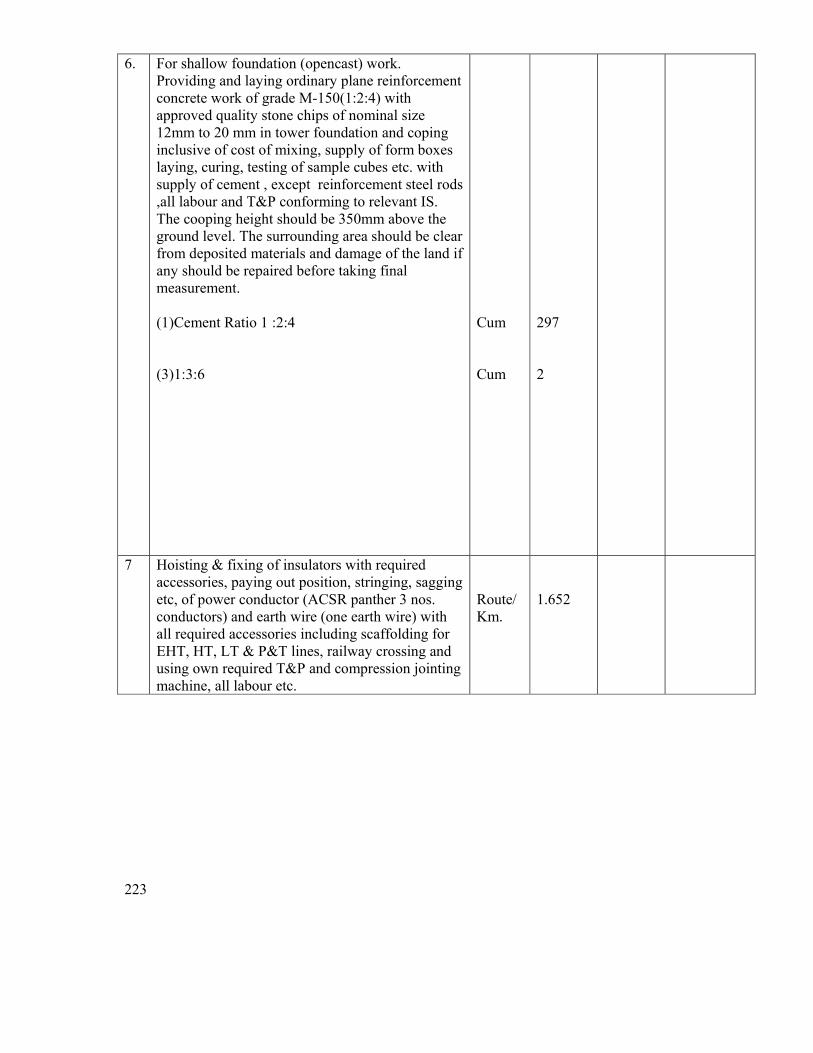
223
6. For shallow foundation (opencast) work. Providing and laying ordinary plane reinforcement concrete work of grade M-150(1:2:4) with approved quality stone chips of nominal size 12mm to 20 mm in tower foundation and coping inclusive of cost of mixing, supply of form boxes laying, curing, testing of sample cubes etc. with supply of cement , except reinforcement steel rods ,all labour and T&P conforming to relevant IS. The cooping height should be 350mm above the ground level. The surrounding area should be clear from deposited materials and damage of the land if any should be repaired before taking final measurement. (1)Cement Ratio 1 :2:4 (3)1:3:6
Cum Cum
297 2
7 Hoisting & fixing of insulators with required accessories, paying out position, stringing, sagging etc, of power conductor (ACSR panther 3 nos. conductors) and earth wire (one earth wire) with all required accessories including scaffolding for EHT, HT, LT & P&T lines, railway crossing and using own required T&P and compression jointing machine, all labour etc.
Route/ Km.
1.652
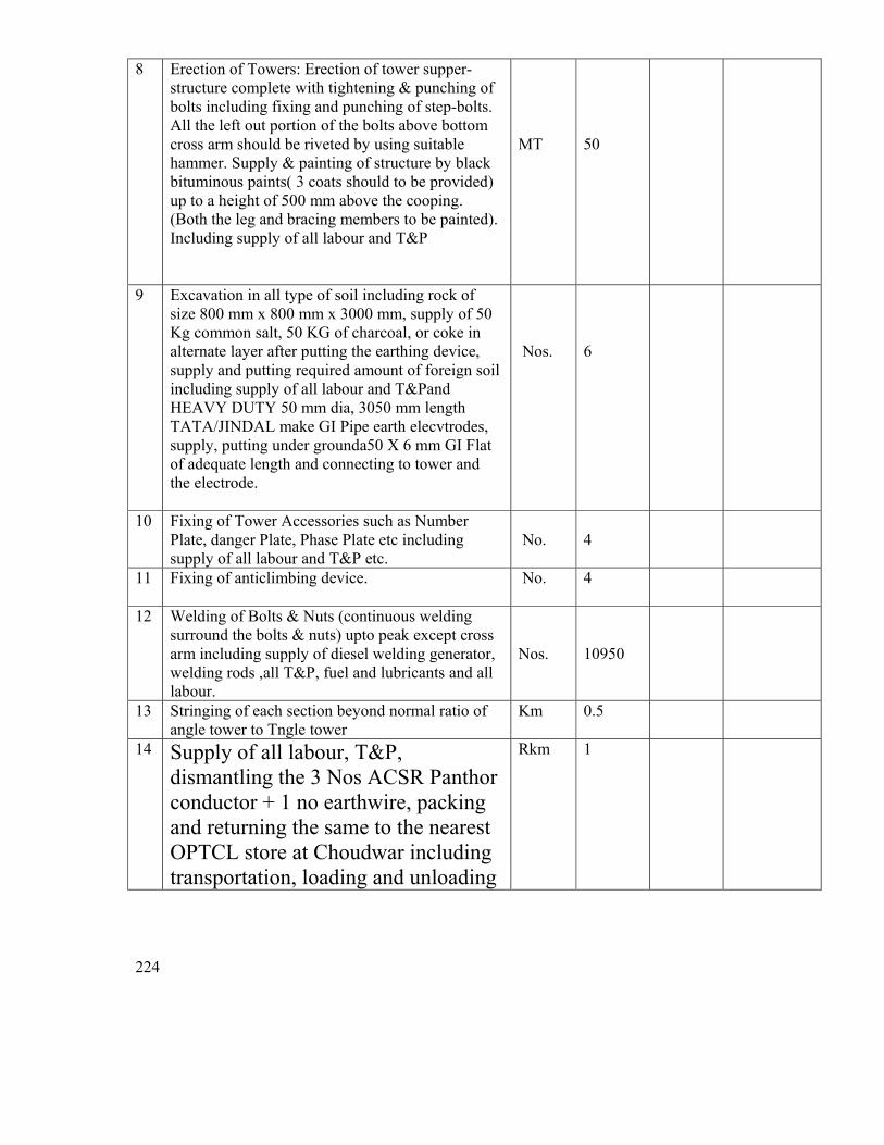
224
8 Erection of Towers: Erection of tower supper-structure complete with tightening & punching of bolts including fixing and punching of step-bolts. All the left out portion of the bolts above bottom cross arm should be riveted by using suitable hammer. Supply & painting of structure by black bituminous paints( 3 coats should to be provided) up to a height of 500 mm above the cooping. (Both the leg and bracing members to be painted). Including supply of all labour and T&P
MT
50
9 Excavation in all type of soil including rock of size 800 mm x 800 mm x 3000 mm, supply of 50 Kg common salt, 50 KG of charcoal, or coke in alternate layer after putting the earthing device, supply and putting required amount of foreign soil including supply of all labour and T&Pand HEAVY DUTY 50 mm dia, 3050 mm length TATA/JINDAL make GI Pipe earth elecvtrodes, supply, putting under grounda50 X 6 mm GI Flat of adequate length and connecting to tower and the electrode.
Nos.
6
10 Fixing of Tower Accessories such as Number Plate, danger Plate, Phase Plate etc including supply of all labour and T&P etc.
No.
4
11 Fixing of anticlimbing device. No. 4
12 Welding of Bolts & Nuts (continuous welding surround the bolts & nuts) upto peak except cross arm including supply of diesel welding generator, welding rods ,all T&P, fuel and lubricants and all labour.
Nos.
10950
13 Stringing of each section beyond normal ratio of angle tower to Tngle tower
Km 0.5
14 Supply of all labour, T&P, dismantling the 3 Nos ACSR Panthor conductor + 1 no earthwire, packing and returning the same to the nearest OPTCL store at Choudwar including transportation, loading and unloading
Rkm 1
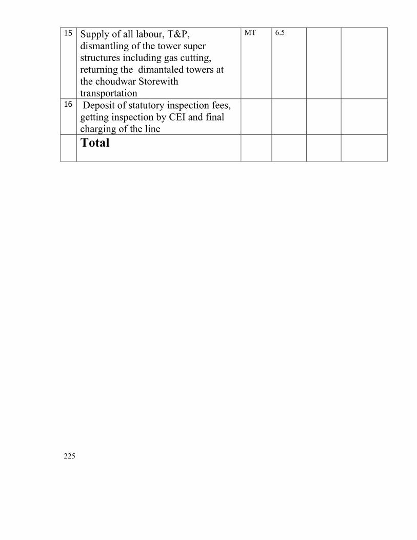
225
15 Supply of all labour, T&P, dismantling of the tower super structures including gas cutting, returning the dimantaled towers at the choudwar Storewith transportation
MT 6.5
16 Deposit of statutory inspection fees, getting inspection by CEI and final charging of the line
Total
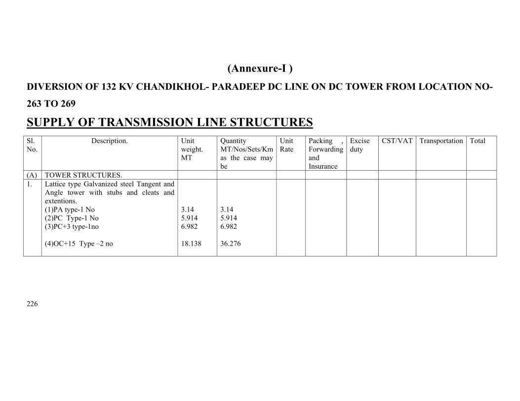
226
(Annexure-I ) DIVERSION OF 132 KV CHANDIKHOL- PARADEEP DC LINE ON DC TOWER FROM LOCATION NO-
263 TO 269 SUPPLY OF TRANSMISSION LINE STRUCTURES
Sl. No.
Description. Unit weight. MT
Quantity MT/Nos/Sets/Km as the case may be
Unit Rate
Packing , Forwarding and Insurance
Excise duty
CST/VAT Transportation Total
(A) TOWER STRUCTURES. 1. Lattice type Galvanized steel Tangent and
Angle tower with stubs and cleats and extentions. (1)PA type-1 No (2)PC Type-1 No (3)PC+3 type-1no
(4)OC+15 Type –2 no
3.14 5.914 6.982 18.138
3.14 5.914 6.982 36.276
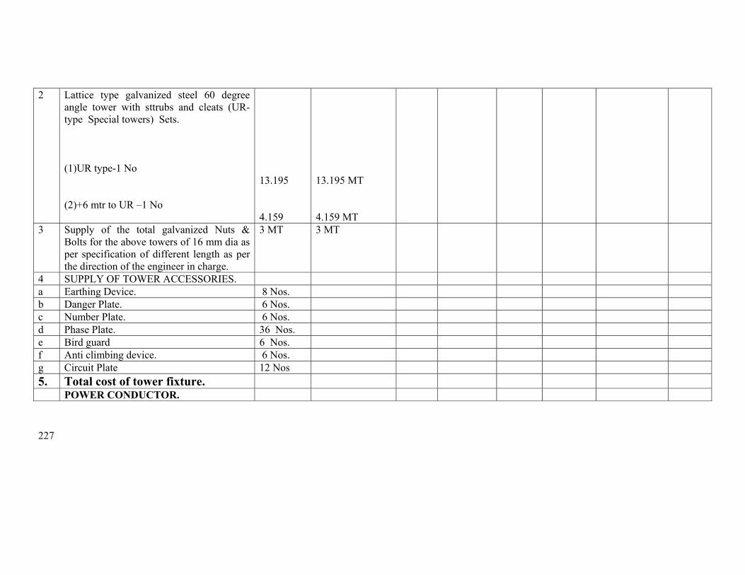
227
2 Lattice type galvanized steel 60 degree angle tower with sttrubs and cleats (UR- type Special towers) Sets.
(1)UR type-1 No (2)+6 mtr to UR –1 No
13.195 4.159
13.195 MT 4.159 MT
3 Supply of the total galvanized Nuts & Bolts for the above towers of 16 mm dia as per specification of different length as per the direction of the engineer in charge.
3 MT 3 MT
4 SUPPLY OF TOWER ACCESSORIES. a Earthing Device. 8 Nos. b Danger Plate. 6 Nos. c Number Plate. 6 Nos. d Phase Plate. 36 Nos. e Bird guard 6 Nos. f Anti climbing device. 6 Nos. g Circuit Plate 12 Nos 5. Total cost of tower fixture. POWER CONDUCTOR.
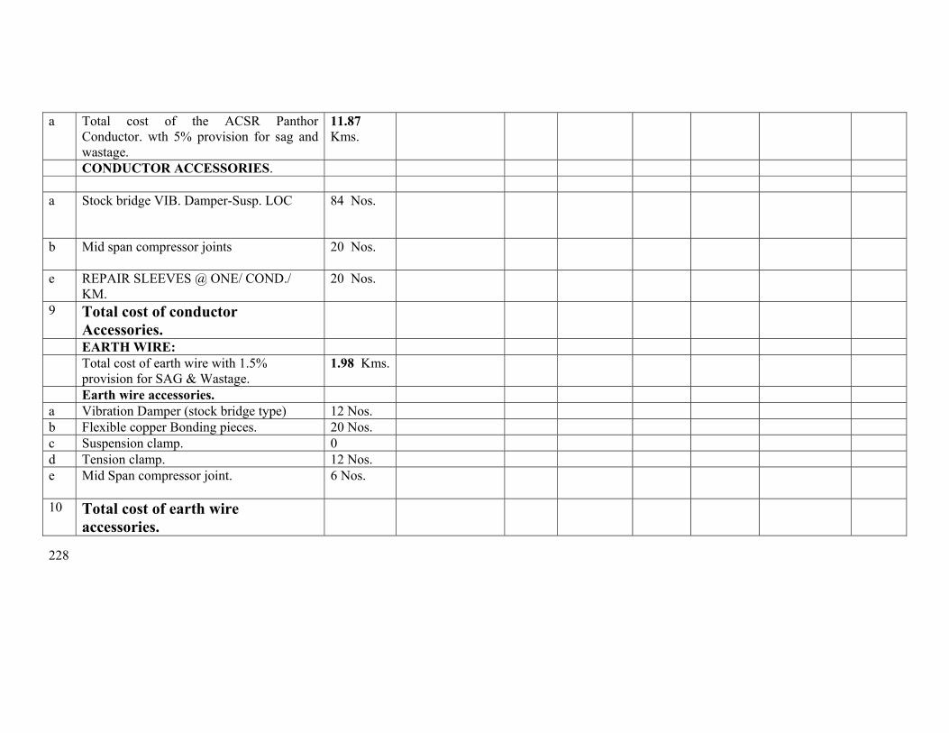
228
a Total cost of the ACSR Panthor Conductor. wth 5% provision for sag and wastage.
11.87 Kms.
CONDUCTOR ACCESSORIES. a Stock bridge VIB. Damper-Susp. LOC 84 Nos.
b Mid span compressor joints
20 Nos.
e REPAIR SLEEVES @ ONE/ COND./ KM.
20 Nos.
9 Total cost of conductor Accessories.
EARTH WIRE: Total cost of earth wire with 1.5%
provision for SAG & Wastage. 1.98 Kms.
Earth wire accessories. a Vibration Damper (stock bridge type) 12 Nos. b Flexible copper Bonding pieces. 20 Nos. c Suspension clamp. 0 d Tension clamp. 12 Nos. e Mid Span compressor joint. 6 Nos.
10 Total cost of earth wire accessories.
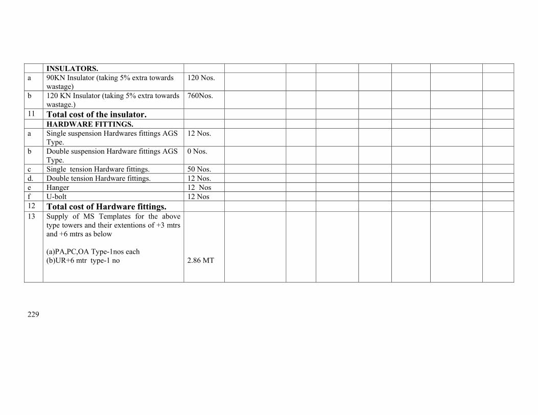
229
INSULATORS. a 90KN Insulator (taking 5% extra towards
wastage) 120 Nos.
b 120 KN Insulator (taking 5% extra towards wastage.)
760Nos.
11 Total cost of the insulator. HARDWARE FITTINGS. a Single suspension Hardwares fittings AGS
Type. 12 Nos.
b Double suspension Hardware fittings AGS Type.
0 Nos.
c Single tension Hardware fittings. 50 Nos. d. Double tension Hardware fittings. 12 Nos. e Hanger 12 Nos f U-bolt 12 Nos 12 Total cost of Hardware fittings. 13 Supply of MS Templates for the above
type towers and their extentions of +3 mtrs and +6 mtrs as below
(a)PA,PC,OA Type-1nos each (b)UR+6 mtr type-1 no
2.86 MT

230
Erection price schedule for Loc263 to 269
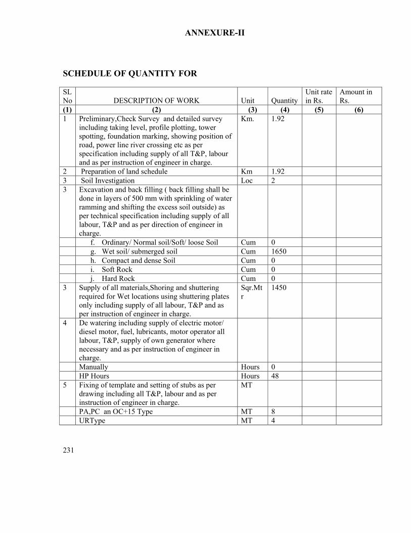
231
ANNEXURE-II SCHEDULE OF QUANTITY FOR SL No
DESCRIPTION OF WORK
Unit
Quantity
Unit rate in Rs.
Amount in Rs.
(1) (2) (3) (4) (5) (6) 1 Preliminary,Check Survey and detailed survey
including taking level, profile plotting, tower spotting, foundation marking, showing position of road, power line river crossing etc as per specification including supply of all T&P, labour and as per instruction of engineer in charge.
Km. 1.92
2 Preparation of land schedule Km 1.92 3 Soil Investigation Loc 2 3 Excavation and back filling ( back filling shall be
done in layers of 500 mm with sprinkling of water ramming and shifting the excess soil outside) as per technical specification including supply of all labour, T&P and as per direction of engineer in charge.
f. Ordinary/ Normal soil/Soft/ loose Soil Cum 0 g. Wet soil/ submerged soil Cum 1650 h. Compact and dense Soil Cum 0 i. Soft Rock Cum 0 j. Hard Rock Cum 0 3 Supply of all materials,Shoring and shuttering
required for Wet locations using shuttering plates only including supply of all labour, T&P and as per instruction of engineer in charge.
Sqr.Mtr
1450
4 De watering including supply of electric motor/ diesel motor, fuel, lubricants, motor operator all labour, T&P, supply of own generator where necessary and as per instruction of engineer in charge.
Manually Hours 0 HP Hours Hours 48 5 Fixing of template and setting of stubs as per
drawing including all T&P, labour and as per instruction of engineer in charge.
MT
PA,PC an OC+15 Type MT 8 URType MT 4

232
6. For shallow foundation (opencast) work. Providing and laying ordinary plane reinforcement concrete work of grade M-150(1:2:4) with approved quality stone chips of nominal size 12mm to 20 mm in tower foundation and coping inclusive of cost of mixing, supply of form boxes laying, curing, testing of sample cubes etc. with supply of cement , except reinforcement steel rods ,all labour and T&P conforming to relevant IS. The cooping height should be 350mm above the ground level. The surrounding area should be clear from deposited materials and damage of the land if any should be repaired before taking final measurement. (1)Cement Ratio 1 :2:4 (3)1:3:6
Cum Cum
450 2
7 Hoisting & fixing of insulators with required accessories, paying out position, stringing, sagging etc, of power conductor (ACSR panther 6 nos. conductors) and earth wire (one earth wire) with all required accessories including scaffolding for EHT, HT, LT & P&T lines, railway crossing and using own required T&P and compression jointing machine, all labour etc.
Route/ Km.
1.92

233
8 Erection of Towers: Erection of tower supper-structure complete with tightening & punching of bolts including fixing and punching of step-bolts. All the left out portion of the bolts above bottom cross arm should be riveted by using suitable hammer. Supply & painting of structure by black bituminous paints( 3 coats should to be provided) up to a height of 500 mm above the cooping. (Both the leg and bracing members to be painted). Including supply of all labour and T&P
MT
65
9 Excavation in all type of soil including rock of size 800 mm x 800 mm x 3000 mm, supply of 50 Kg common salt, 50 KG of charcoal, or coke in alternate layer after putting the earthing device, supply and putting required amount of foreign soil including supply of all labour and T&Pand HEAVY DUTY 50 mm dia, 3050 mm length TATA/JINDAL make GI Pipe earth elecvtrodes, supply, putting under grounda50 X 6 mm GI Flat of adequate length and connecting to tower and the electrode.
Nos.
8
10 Fixing of Tower Accessories such as Number Plate, danger Plate, Phase Plate etc including supply of all labour and T&P etc.
No.
6
11 Fixing of anticlimbing device. No. 6
12 Welding of Bolts & Nuts (continuous welding surround the bolts & nuts) upto peak except cross arm including supply of diesel welding generator, welding rods ,all T&P, fuel and lubricants and all labour.
Nos.
13950
13 Stringing of each section beyond normal ratio of angle tower to Tngle tower
Km 1
14 Supply of all labour, T&P, dismantling the 3 Nos ACSR Panthor conductor + 1 no earthwire, packing and returning the same to the nearest OPTCL store at Choudwar including transportation, loading and unloading
Rkm 1.5

234
15 Supply of all labour, T&P, dismantling of the tower super structures including gas cutting, returning the dimantaled towers at the choudwar Storewith transportation
MT 11
16 Deposit of statutory inspection fees, getting inspection by CEI and final charging of the line
Lots
Total
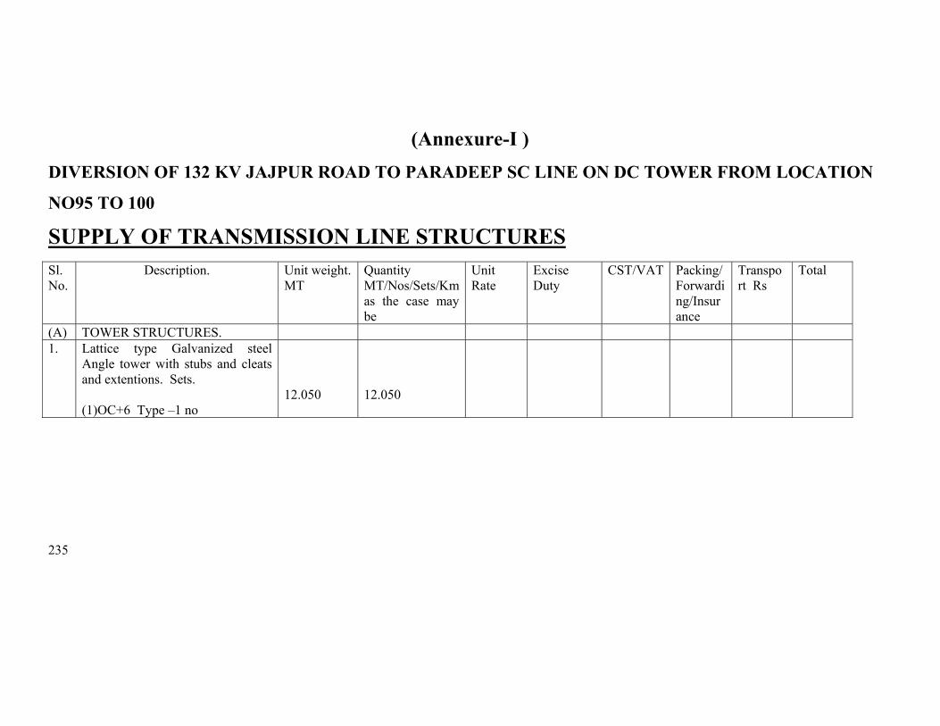
235
(Annexure-I )
DIVERSION OF 132 KV JAJPUR ROAD TO PARADEEP SC LINE ON DC TOWER FROM LOCATION
NO95 TO 100 SUPPLY OF TRANSMISSION LINE STRUCTURES
Sl. No.
Description. Unit weight. MT
Quantity MT/Nos/Sets/Km as the case may be
Unit Rate
Excise Duty
CST/VAT Packing/Forwarding/Insurance
Transport Rs
Total
(A) TOWER STRUCTURES. 1. Lattice type Galvanized steel
Angle tower with stubs and cleats and extentions. Sets.
(1)OC+6 Type –1 no
12.050
12.050
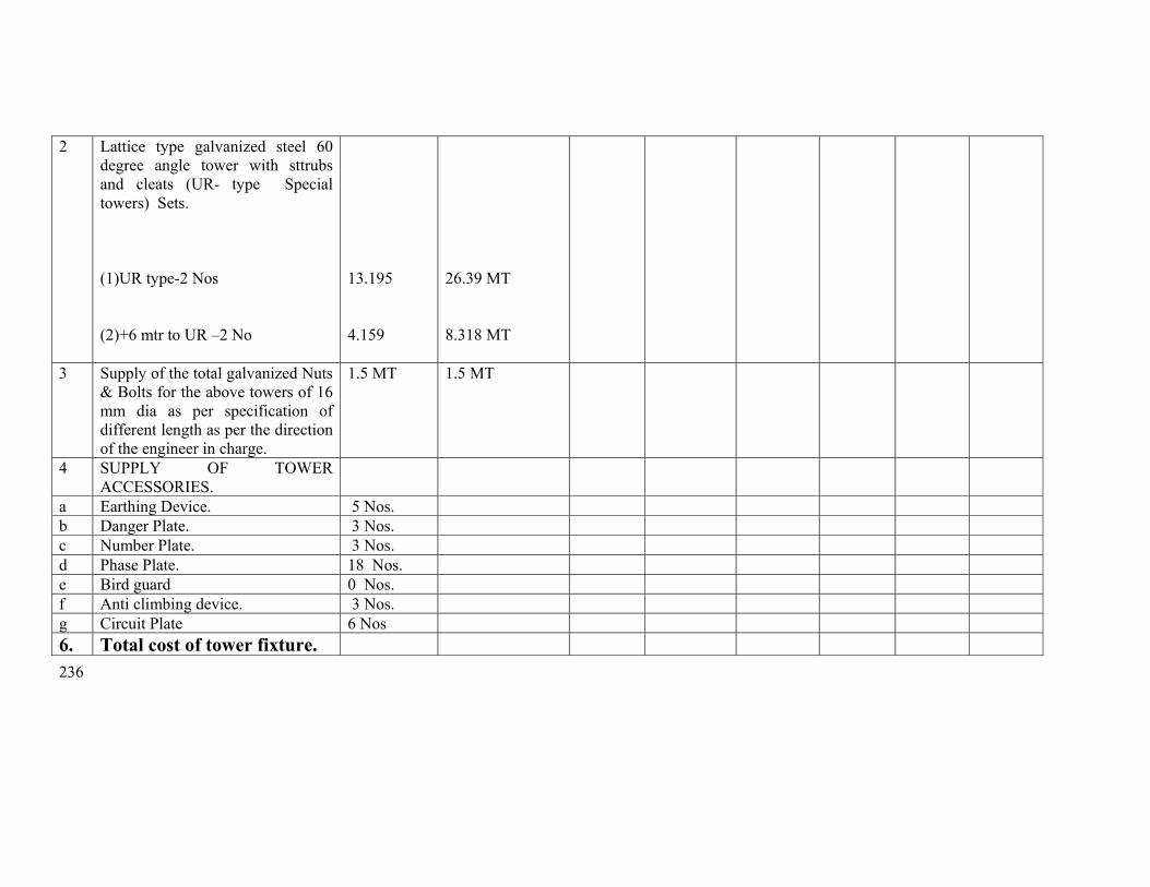
236
2 Lattice type galvanized steel 60 degree angle tower with sttrubs and cleats (UR- type Special towers) Sets.
(1)UR type-2 Nos (2)+6 mtr to UR –2 No
13.195 4.159
26.39 MT 8.318 MT
3 Supply of the total galvanized Nuts & Bolts for the above towers of 16 mm dia as per specification of different length as per the direction of the engineer in charge.
1.5 MT 1.5 MT
4 SUPPLY OF TOWER ACCESSORIES.
a Earthing Device. 5 Nos. b Danger Plate. 3 Nos. c Number Plate. 3 Nos. d Phase Plate. 18 Nos. e Bird guard 0 Nos. f Anti climbing device. 3 Nos. g Circuit Plate 6 Nos 6. Total cost of tower fixture.
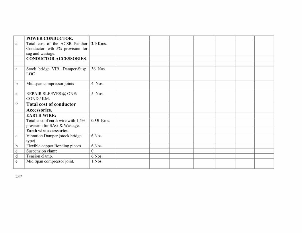
237
POWER CONDUCTOR. a Total cost of the ACSR Panthor
Conductor. wth 5% provision for sag and wastage.
2.0 Kms.
CONDUCTOR ACCESSORIES. a Stock bridge VIB. Damper-Susp.
LOC 36 Nos.
b Mid span compressor joints
4 Nos.
e REPAIR SLEEVES @ ONE/ COND./ KM.
5 Nos.
9 Total cost of conductor Accessories.
EARTH WIRE: Total cost of earth wire with 1.5%
provision for SAG & Wastage. 0.35 Kms.
Earth wire accessories. a Vibration Damper (stock bridge
type) 6 Nos.
b Flexible copper Bonding pieces. 6 Nos. c Suspension clamp. 0. d Tension clamp. 6 Nos. e Mid Span compressor joint. 1 Nos.

238
10 Total cost of earth wire accessories.
INSULATORS. a 90KN Insulator (taking 5% extra
towards wastage) 0Nos.
b 120 KN Insulator (taking 5% extra towards wastage.)
504Nos.
11 Total cost of the insulator. HARDWARE FITTINGS. a Single suspension Hardwares
fittings AGS Type. 0 Nos.
b Double suspension Hardware fittings AGS Type.
0 Nos.
c Single tension Hardware fittings. 24 Nos. d. Double tension Hardware fittings. 12 Nos. e Hanger 4 Nos f U-bolt 4 Nos 12 Total cost of Hardware
fittings.

239
13 Supply of MS Templates for the above type towers and their extentions of +3 mtrs and +6 mtrs as below
(c) OC Type-1nos (d) UR+6 MTR
type-1 no
2.0 MT

240
Erection schedule for Loc 95 to 100

241
ANNEXURE-II SCHEDULE OF QUANTITY FOR SL No
DESCRIPTION OF WORK
Unit
Quantity
Unit rate in Rs.
Amount in Rs.
(1) (2) (3) (4) (5) (6) 1 Preliminary,Check Survey and detailed survey
including taking level, profile plotting, tower spotting, foundation marking, showing position of road, power line river crossing etc as per specification including supply of all T&P, labour and as per instruction of engineer in charge.
Km. 1.53
2 Preparation of land schedule Km 1.53 3 Soil Investigation Loc 3 3 Excavation and back filling ( back filling shall be
done in layers of 500 mm with sprinkling of water ramming and shifting the excess soil outside) as per technical specification including supply of all labour, T&P and as per direction of engineer in charge.
Ordinary/ Normal soil/Soft/ loose Soil Cum 20 Wet soil/ submerged soil Cum 700 Compact and dense Soil Cum 0 Soft Rock Cum 0 Hard Rock Cum 0 3 Supply of all materials,Shoring and shuttering
required for Wet locations using shuttering plates only including supply of all labour, T&P and as per instruction of engineer in charge.
Sqr.Mtr
612
4 De watering including supply of electric motor/ diesel motor, fuel, lubricants, motor operator all labour, T&P, supply of own generator where necessary and as per instruction of engineer in charge.
Manually Hours 0 HP Hours Hours 150 5 Fixing of template and setting of stubs as per
drawing including all T&P, labour and as per instruction of engineer in charge.
MT
OC Type MT 1.66 URType MT 4.0

242
6. For shallow foundation (opencast) work. Providing and laying ordinary plane reinforcement concrete work of grade M-150(1:2:4) with approved quality stone chips of nominal size 12mm to 20 mm in tower foundation and coping inclusive of cost of mixing, supply of form boxes laying, curing, testing of sample cubes etc. with supply of cement , except reinforcement steel rods ,all labour and T&P conforming to relevant IS. The cooping height should be 350mm above the ground level. The surrounding area should be clear from deposited materials and damage of the land if any should be repaired before taking final measurement. (1)Cement Ratio 1 :2:4 (3)1:3:6
Cum Cum
160 1
7 Hoisting & fixing of insulators with required accessories, paying out position, stringing, sagging etc, of power conductor (ACSR panther 6 nos. conductors) and earth wire (one earth wire) with all required accessories including scaffolding for EHT, HT, LT & P&T lines, railway crossing and using own required T&P and compression jointing machine, all labour etc.
Route/ Km.
0.595
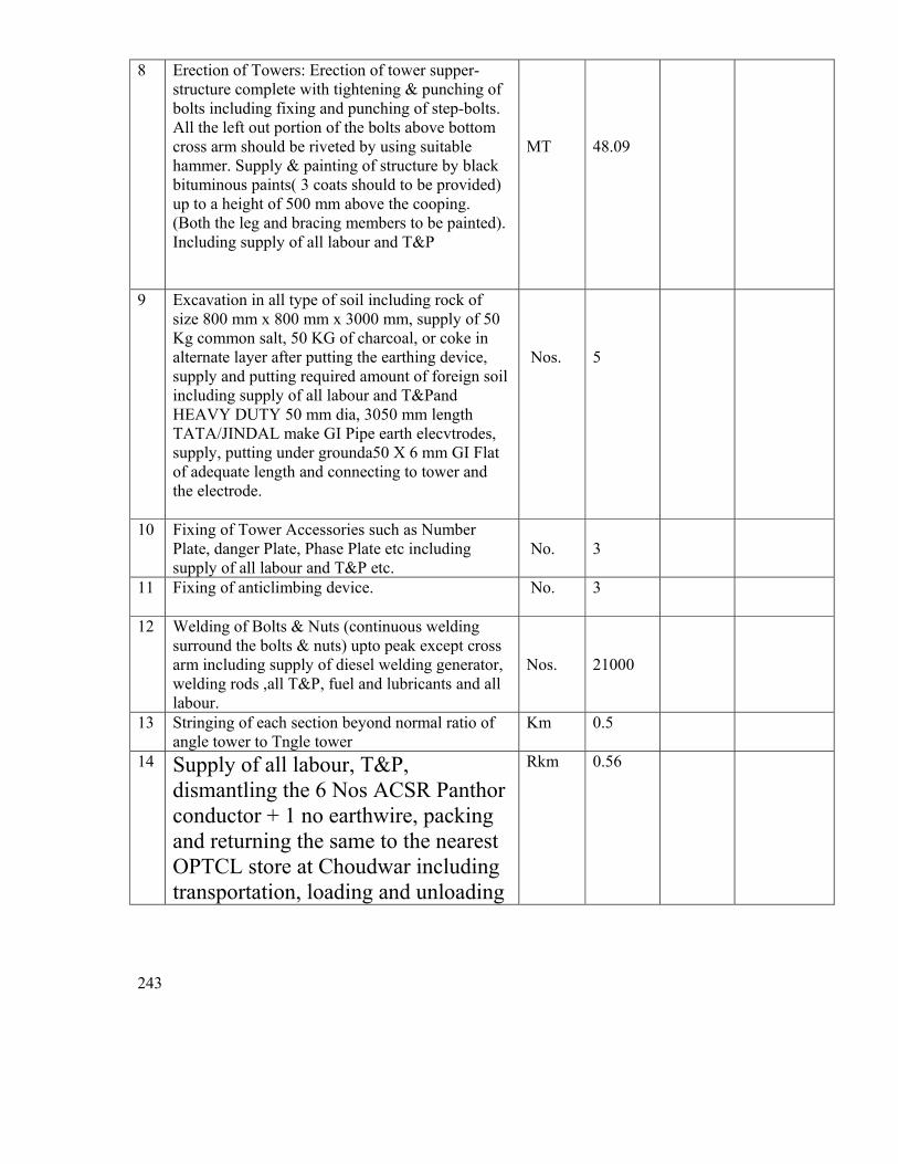
243
8 Erection of Towers: Erection of tower supper-structure complete with tightening & punching of bolts including fixing and punching of step-bolts. All the left out portion of the bolts above bottom cross arm should be riveted by using suitable hammer. Supply & painting of structure by black bituminous paints( 3 coats should to be provided) up to a height of 500 mm above the cooping. (Both the leg and bracing members to be painted). Including supply of all labour and T&P
MT
48.09
9 Excavation in all type of soil including rock of size 800 mm x 800 mm x 3000 mm, supply of 50 Kg common salt, 50 KG of charcoal, or coke in alternate layer after putting the earthing device, supply and putting required amount of foreign soil including supply of all labour and T&Pand HEAVY DUTY 50 mm dia, 3050 mm length TATA/JINDAL make GI Pipe earth elecvtrodes, supply, putting under grounda50 X 6 mm GI Flat of adequate length and connecting to tower and the electrode.
Nos.
5
10 Fixing of Tower Accessories such as Number Plate, danger Plate, Phase Plate etc including supply of all labour and T&P etc.
No.
3
11 Fixing of anticlimbing device. No. 3
12 Welding of Bolts & Nuts (continuous welding surround the bolts & nuts) upto peak except cross arm including supply of diesel welding generator, welding rods ,all T&P, fuel and lubricants and all labour.
Nos.
21000
13 Stringing of each section beyond normal ratio of angle tower to Tngle tower
Km 0.5
14 Supply of all labour, T&P, dismantling the 6 Nos ACSR Panthor conductor + 1 no earthwire, packing and returning the same to the nearest OPTCL store at Choudwar including transportation, loading and unloading
Rkm 0.56

244
15 Supply of all labour, T&P, dismantling OF TOWER SUPER STRUCTURES INCLUDING GAS CUTTING, packing and returning the same to the nearest OPTCL store at Choudwar including transportation, loading and unloading
MT 8.6
16 Deposit of statutory inspection fees, getting inspection by CEI and final charging of the line
Lot 1
17 RR Masonary work with supply of all materials and labour in the ratio 1:5
Cum 90
18 Back filling with borrowed earth with lead more than 30 mts
Cum 30
Total
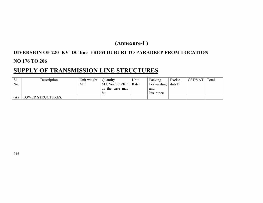
245
(Annexure-I ) DIVERSION OF 220 KV DC line FROM DUBURI TO PARADEEP FROM LOCATION
NO 176 TO 206 SUPPLY OF TRANSMISSION LINE STRUCTURES
Sl. No.
Description. Unit weight. MT
Quantity MT/Nos/Sets/Km as the case may be
Unit Rate
Packing , Forwarding and Insurance
Excise dutyD
CST/VAT Total
(A) TOWER STRUCTURES.
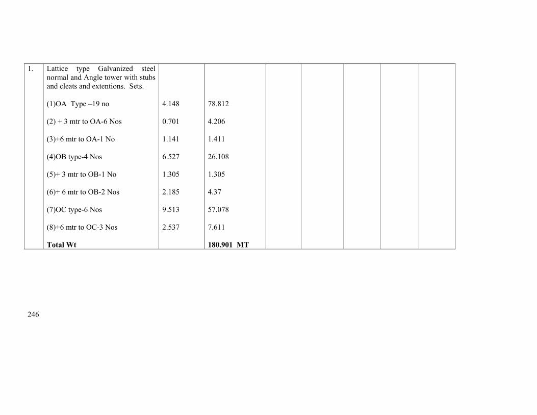
246
1. Lattice type Galvanized steel normal and Angle tower with stubs and cleats and extentions. Sets.
(1)OA Type –19 no (2) + 3 mtr to OA-6 Nos (3)+6 mtr to OA-1 No (4)OB type-4 Nos (5)+ 3 mtr to OB-1 No (6)+ 6 mtr to OB-2 Nos (7)OC type-6 Nos (8)+6 mtr to OC-3 Nos Total Wt
4.148 0.701 1.141 6.527 1.305 2.185 9.513 2.537
78.812 4.206 1.411 26.108 1.305 4.37 57.078 7.611 180.901 MT
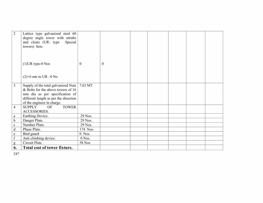
247
2 Lattice type galvanized steel 60 degree angle tower with sttrubs and cleats (UR- type Special towers) Sets.
(1)UR type-0 Nos (2)+6 mtr to UR –0 No
0
0
3 Supply of the total galvanized Nuts & Bolts for the above towers of 16 mm dia as per specification of different length as per the direction of the engineer in charge.
7.63 MT
4 SUPPLY OF TOWER ACCESSORIES.
a Earthing Device. 29 Nos. b Danger Plate. 29 Nos. c Number Plate. 29 Nos. d Phase Plate. 174 Nos. e Bird guard 0 Nos. f Anti climbing device. 0 Nos. g Circuit Plate 58 Nos 6. Total cost of tower fixture.
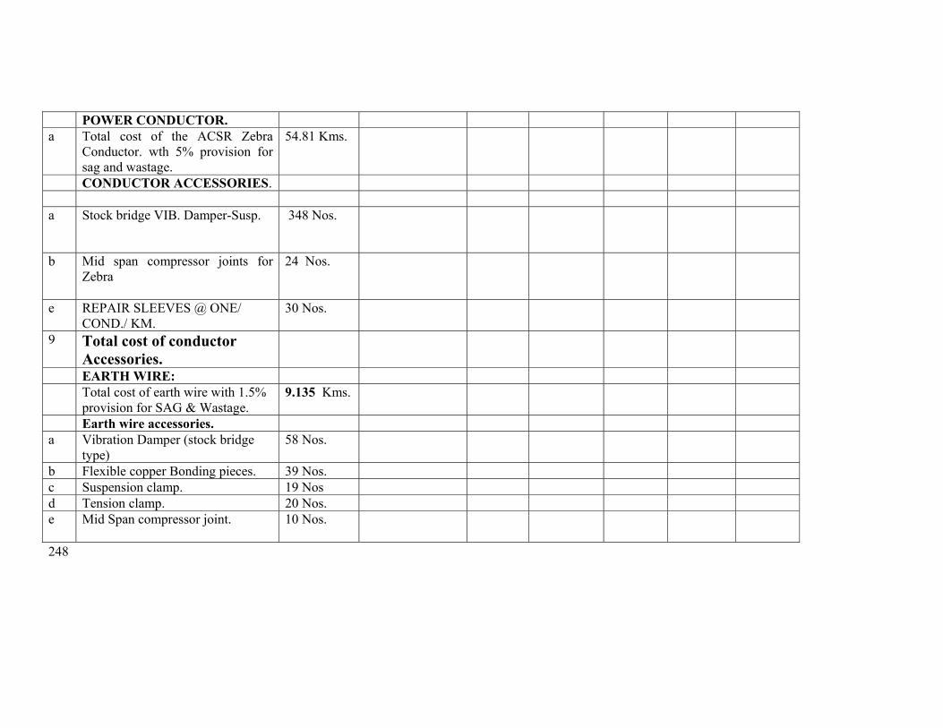
248
POWER CONDUCTOR. a Total cost of the ACSR Zebra
Conductor. wth 5% provision for sag and wastage.
54.81 Kms.
CONDUCTOR ACCESSORIES. a Stock bridge VIB. Damper-Susp. 348 Nos.
b Mid span compressor joints for Zebra
24 Nos.
e REPAIR SLEEVES @ ONE/ COND./ KM.
30 Nos.
9 Total cost of conductor Accessories.
EARTH WIRE: Total cost of earth wire with 1.5%
provision for SAG & Wastage. 9.135 Kms.
Earth wire accessories. a Vibration Damper (stock bridge
type) 58 Nos.
b Flexible copper Bonding pieces. 39 Nos. c Suspension clamp. 19 Nos d Tension clamp. 20 Nos. e Mid Span compressor joint. 10 Nos.
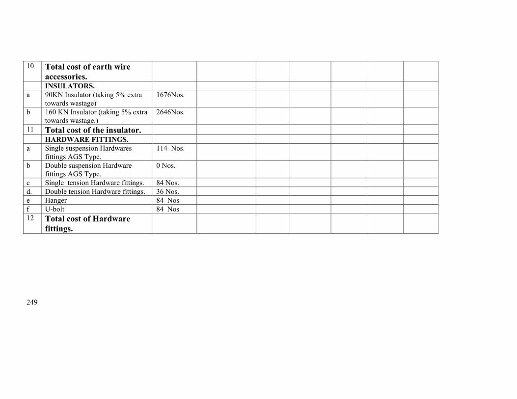
249
10 Total cost of earth wire accessories.
INSULATORS. a 90KN Insulator (taking 5% extra
towards wastage) 1676Nos.
b 160 KN Insulator (taking 5% extra towards wastage.)
2646Nos.
11 Total cost of the insulator. HARDWARE FITTINGS. a Single suspension Hardwares
fittings AGS Type. 114 Nos.
b Double suspension Hardware fittings AGS Type.
0 Nos.
c Single tension Hardware fittings. 84 Nos. d. Double tension Hardware fittings. 36 Nos. e Hanger 84 Nos f U-bolt 84 Nos 12 Total cost of Hardware
fittings.
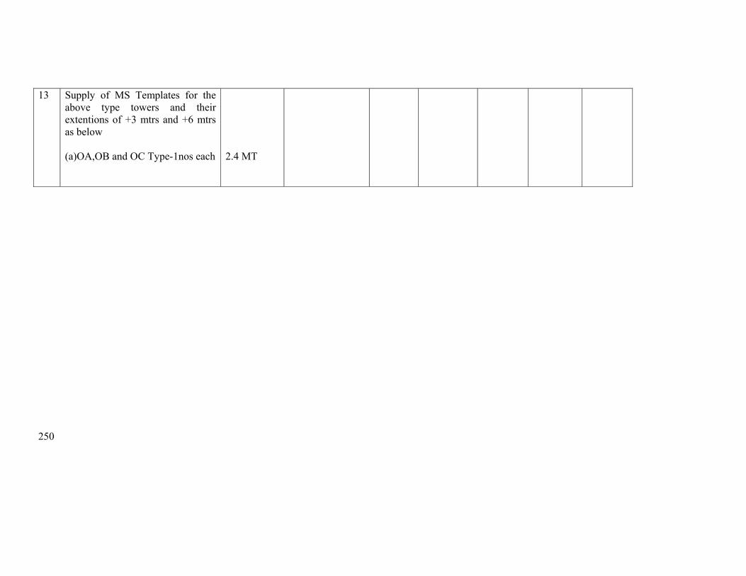
250
13 Supply of MS Templates for the above type towers and their extentions of +3 mtrs and +6 mtrs as below
(a)OA,OB and OC Type-1nos each
2.4 MT
251
Erection Schedule for Loc 176 to 206

252
ANNEXURE-II SCHEDULE OF QUANTITY FOR SL No
DESCRIPTION OF WORK
Unit
Quantity
Unit rate in Rs.
Amount in Rs.
(1) (2) (3) (4) (5) (6) 1 Preliminary,Check Survey and detailed survey
including taking level, profile plotting, tower spotting, foundation marking, showing position of road, power line river crossing etc as per specification including supply of all T&P, labour and as per instruction of engineer in charge.
Km. 9
2 Preparation of land schedule Km 9 3 Soil Investigation Loc 1 3 Excavation and back filling ( back filling shall be
done in layers of 500 mm with sprinkling of water ramming and shifting the excess soil outside) as per technical specification including supply of all labour, T&P and as per direction of engineer in charge.
Ordinary/ Normal soil/Soft/ loose Soil Cum 767 Wet soil/ submerged soil Cum 3250 Compact and dense Soil Cum 0 Soft Rock Cum 0 Hard Rock Cum 0 3 Supply of all materials,Shoring and shuttering
required for Wet locations using shuttering plates only including supply of all labour, T&P and as per instruction of engineer in charge.
Sqr.Mtr
6264
4 De watering including supply of electric motor/ diesel motor, fuel, lubricants, motor operator all labour, T&P, supply of own generator where necessary and as per instruction of engineer in charge.
Manually Hours 0 HP Hours Hours 150 5 Fixing of template and setting of stubs as per
drawing including all T&P, labour and as per instruction of engineer in charge.
MT
OA, OB and OC Type MT 31.281

253
6. For shallow foundation (opencast) work. Providing and laying ordinary plane reinforcement concrete work of grade M-150(1:2:4) with approved quality stone chips of nominal size 12mm to 20 mm in tower foundation and coping inclusive of cost of mixing, supply of form boxes laying, curing, testing of sample cubes etc. with supply of cement , except reinforcement steel rods ,all labour and T&P conforming to relevant IS. The cooping height should be 350mm above the ground level. The surrounding area should be clear from deposited materials and damage of the land if any should be repaired before taking final measurement. (1)Cement Ratio 1 :2:4 (3)1:3:6
Cum Cum
860 18
7 Hoisting & fixing of insulators with required accessories, paying out position, stringing, sagging etc, of power conductor (ACSR Zebra 6 nos. conductors) and earth wire (one earth wire) with all required accessories including scaffolding for EHT, HT, LT & P&T lines, railway crossing and using own required T&P and compression jointing machine, all labour etc.
Route/ Km.
9

254
8 Erection of Towers: Erection of tower supper-structure complete with tightening & punching of bolts including fixing and punching of step-bolts. All the left out portion of the bolts above bottom cross arm should be riveted by using suitable hammer. Supply & painting of structure by black bituminous paints( 3 coats should to be provided) up to a height of 500 mm above the cooping. (Both the leg and bracing members to be painted). Including supply of all labour and T&P
MT
190.55
9 Excavation in all type of soil including rock of size 800 mm x 800 mm x 3000 mm, supply of 50 Kg common salt, 50 KG of charcoal, or coke in alternate layer after putting the earthing device, supply and putting required amount of foreign soil including supply of all labour and T&Pand HEAVY DUTY 50 mm dia, 3050 mm length TATA/JINDAL make GI Pipe earth elecvtrodes, supply, putting under grounda50 X 6 mm GI Flat of adequate length and connecting to tower and the electrode.
Nos.
29
10 Fixing of Tower Accessories such as Number Plate, danger Plate, Phase Plate etc including supply of all labour and T&P etc.
No.
29
11 Fixing of anticlimbing device. No. 0
12 Welding of Bolts & Nuts (continuous welding surround the bolts & nuts) upto peak except cross arm including supply of diesel welding generator, welding rods ,all T&P, fuel and lubricants and all labour.
Nos.
21000
13 Stringing of each section beyond normal ratio of angle tower to Tngle tower
Km 0
14 Supply of all labour, T&P, dismantling the 6 Nos ACSR Zebra conductor + 1 no earthwire, packing and returning the same to the nearest OPTCL store at Choudwar including transportation, loading and unloading
Rkm 7.31
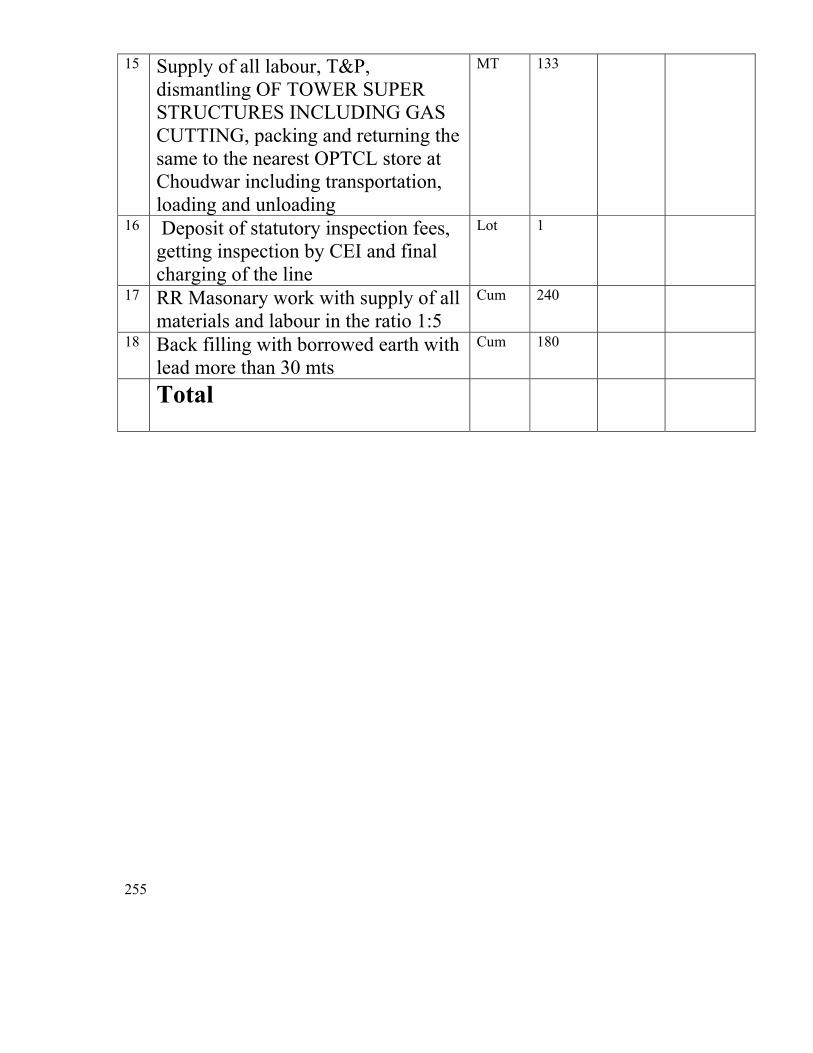
255
15 Supply of all labour, T&P, dismantling OF TOWER SUPER STRUCTURES INCLUDING GAS CUTTING, packing and returning the same to the nearest OPTCL store at Choudwar including transportation, loading and unloading
MT 133
16 Deposit of statutory inspection fees, getting inspection by CEI and final charging of the line
Lot 1
17 RR Masonary work with supply of all materials and labour in the ratio 1:5
Cum 240
18 Back filling with borrowed earth with lead more than 30 mts
Cum 180
Total
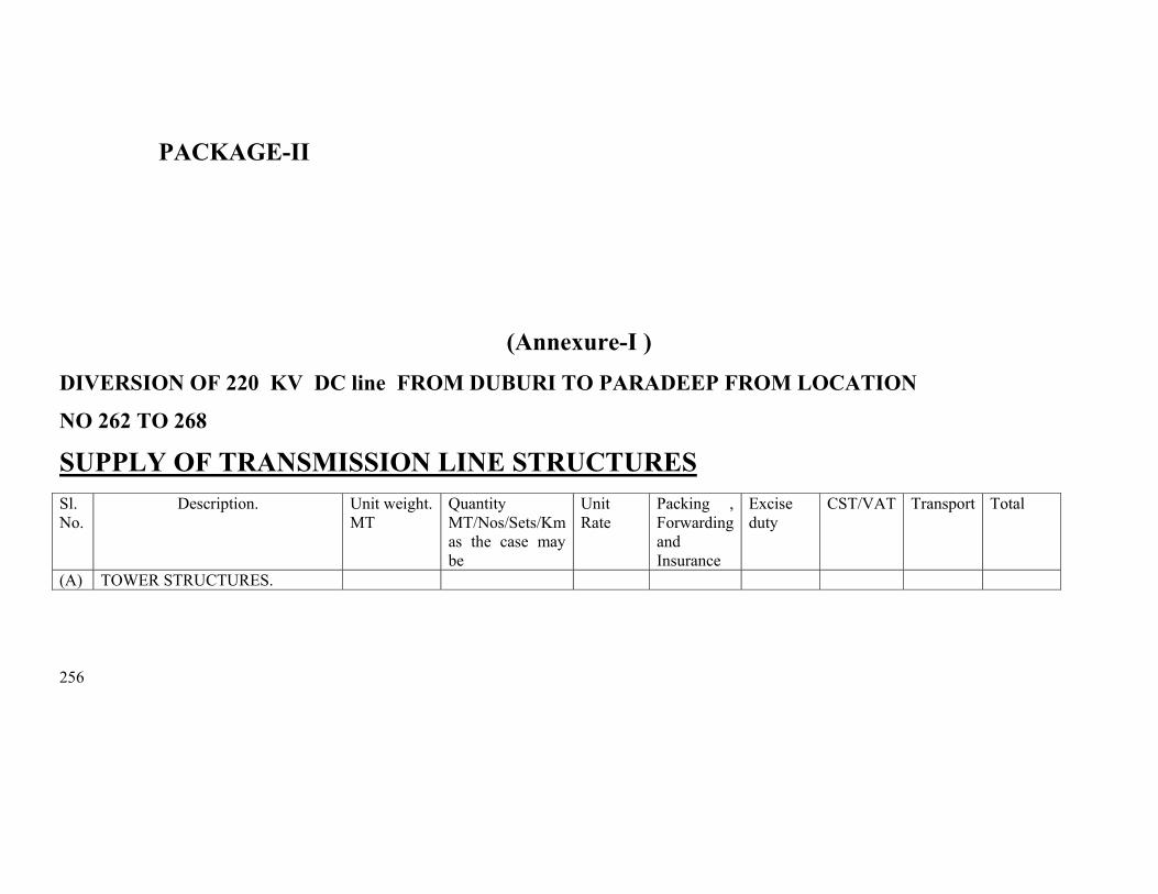
256
PACKAGE-II
(Annexure-I ) DIVERSION OF 220 KV DC line FROM DUBURI TO PARADEEP FROM LOCATION
NO 262 TO 268 SUPPLY OF TRANSMISSION LINE STRUCTURES
Sl. No.
Description. Unit weight. MT
Quantity MT/Nos/Sets/Km as the case may be
Unit Rate
Packing , Forwarding and Insurance
Excise duty
CST/VAT Transport Total
(A) TOWER STRUCTURES.
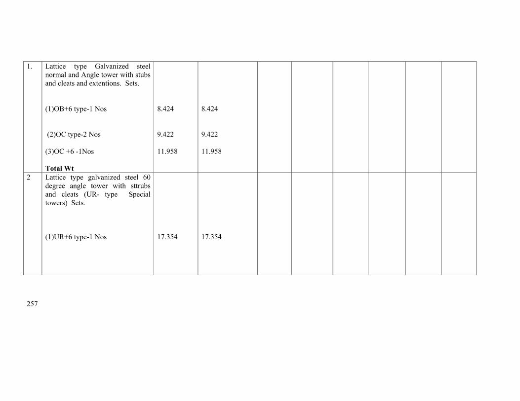
257
1. Lattice type Galvanized steel normal and Angle tower with stubs and cleats and extentions. Sets.
(1)OB+6 type-1 Nos (2)OC type-2 Nos (3)OC +6 -1Nos Total Wt
8.424 9.422 11.958
8.424 9.422 11.958
2 Lattice type galvanized steel 60 degree angle tower with sttrubs and cleats (UR- type Special towers) Sets.
(1)UR+6 type-1 Nos
17.354
17.354
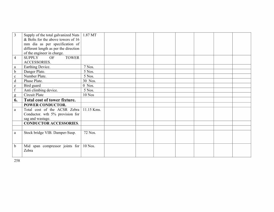
258
3 Supply of the total galvanized Nuts & Bolts for the above towers of 16 mm dia as per specification of different length as per the direction of the engineer in charge.
1.87 MT
4 SUPPLY OF TOWER ACCESSORIES.
a Earthing Device. 7 Nos. b Danger Plate. 5 Nos. c Number Plate. 5 Nos. d Phase Plate. 30 Nos. e Bird guard 0 Nos. f Anti climbing device. 5 Nos. g Circuit Plate 10 Nos 6. Total cost of tower fixture. POWER CONDUCTOR. a Total cost of the ACSR Zebra
Conductor. wth 5% provision for sag and wastage.
11.15 Kms.
CONDUCTOR ACCESSORIES. a Stock bridge VIB. Damper-Susp. 72 Nos.
b Mid span compressor joints for Zebra
10 Nos.
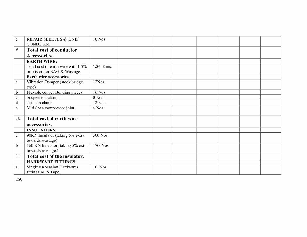
259
e REPAIR SLEEVES @ ONE/ COND./ KM.
10 Nos.
9 Total cost of conductor Accessories.
EARTH WIRE: Total cost of earth wire with 1.5%
provision for SAG & Wastage. 1.86 Kms.
Earth wire accessories. a Vibration Damper (stock bridge
type) 12Nos.
b Flexible copper Bonding pieces. 16 Nos. c Suspension clamp. 0 Nos d Tension clamp. 12 Nos. e Mid Span compressor joint. 4 Nos.
10 Total cost of earth wire accessories.
INSULATORS. a 90KN Insulator (taking 5% extra
towards wastage) 300 Nos.
b 160 KN Insulator (taking 5% extra towards wastage.)
1700Nos.
11 Total cost of the insulator. HARDWARE FITTINGS. a Single suspension Hardwares
fittings AGS Type. 10 Nos.
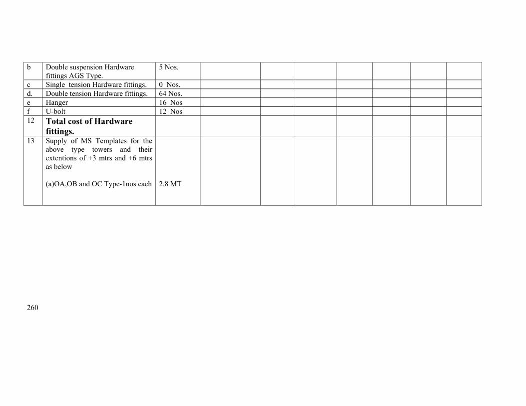
260
b Double suspension Hardware fittings AGS Type.
5 Nos.
c Single tension Hardware fittings. 0 Nos. d. Double tension Hardware fittings. 64 Nos. e Hanger 16 Nos f U-bolt 12 Nos 12 Total cost of Hardware
fittings.
13 Supply of MS Templates for the above type towers and their extentions of +3 mtrs and +6 mtrs as below
(a)OA,OB and OC Type-1nos each
2.8 MT
261
Erection Schedule for Loc 262 to 268
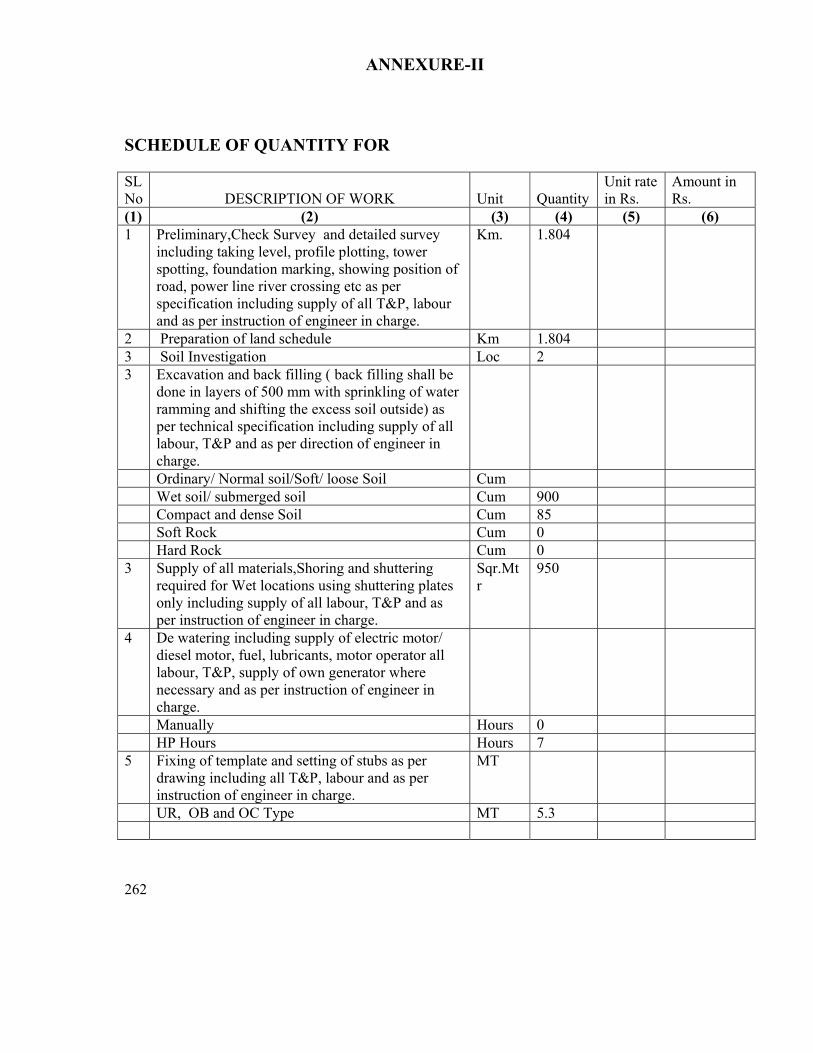
262
ANNEXURE-II SCHEDULE OF QUANTITY FOR SL No
DESCRIPTION OF WORK
Unit
Quantity
Unit rate in Rs.
Amount in Rs.
(1) (2) (3) (4) (5) (6) 1 Preliminary,Check Survey and detailed survey
including taking level, profile plotting, tower spotting, foundation marking, showing position of road, power line river crossing etc as per specification including supply of all T&P, labour and as per instruction of engineer in charge.
Km. 1.804
2 Preparation of land schedule Km 1.804 3 Soil Investigation Loc 2 3 Excavation and back filling ( back filling shall be
done in layers of 500 mm with sprinkling of water ramming and shifting the excess soil outside) as per technical specification including supply of all labour, T&P and as per direction of engineer in charge.
Ordinary/ Normal soil/Soft/ loose Soil Cum Wet soil/ submerged soil Cum 900 Compact and dense Soil Cum 85 Soft Rock Cum 0 Hard Rock Cum 0 3 Supply of all materials,Shoring and shuttering
required for Wet locations using shuttering plates only including supply of all labour, T&P and as per instruction of engineer in charge.
Sqr.Mtr
950
4 De watering including supply of electric motor/ diesel motor, fuel, lubricants, motor operator all labour, T&P, supply of own generator where necessary and as per instruction of engineer in charge.
Manually Hours 0 HP Hours Hours 7 5 Fixing of template and setting of stubs as per
drawing including all T&P, labour and as per instruction of engineer in charge.
MT
UR, OB and OC Type MT 5.3

263
6. For shallow foundation (opencast) work. Providing and laying ordinary plane reinforcement concrete work of grade M-150(1:2:4) with approved quality stone chips of nominal size 12mm to 20 mm in tower foundation and coping inclusive of cost of mixing, supply of form boxes laying, curing, testing of sample cubes etc. with supply of cement , except reinforcement steel rods ,all labour and T&P conforming to relevant IS. The cooping height should be 350mm above the ground level. The surrounding area should be clear from deposited materials and damage of the land if any should be repaired before taking final measurement. (1)Cement Ratio 1 :2:4 (3)1:3:6
Cum Cum
252 1
7 Hoisting & fixing of insulators with required accessories, paying out position, stringing, sagging etc, of power conductor (ACSR Zebra 6 nos. conductors) and earth wire (one earth wire) with all required accessories including scaffolding for EHT, HT, LT & P&T lines, railway crossing and using own required T&P and compression jointing machine, all labour etc.
Route/ Km.
1.804

264
8 Erection of Towers: Erection of tower supper-structure complete with tightening & punching of bolts including fixing and punching of step-bolts. All the left out portion of the bolts above bottom cross arm should be riveted by using suitable hammer. Supply & painting of structure by black bituminous paints( 3 coats should to be provided) up to a height of 500 mm above the cooping. (Both the leg and bracing members to be painted). Including supply of all labour and T&P
MT
58.5
9 Excavation in all type of soil including rock of size 800 mm x 800 mm x 3000 mm, supply of 50 Kg common salt, 50 KG of charcoal, or coke in alternate layer after putting the earthing device, supply and putting required amount of foreign soil including supply of all labour and T&Pand HEAVY DUTY 50 mm dia, 3050 mm length TATA/JINDAL make GI Pipe earth elecvtrodes, supply, putting under grounda50 X 6 mm GI Flat of adequate length and connecting to tower and the electrode.
Nos.
7
10 Fixing of Tower Accessories such as Number Plate, danger Plate, Phase Plate etc including supply of all labour and T&P etc.
No.
5
11 Fixing of anticlimbing device. No. 5
12 Welding of Bolts & Nuts (continuous welding surround the bolts & nuts) upto peak except cross arm including supply of diesel welding generator, welding rods ,all T&P, fuel and lubricants and all labour.
Nos.
9550
13 Stringing of each section beyond normal ratio of angle tower to Tngle tower
Km 1
14 Supply of all labour, T&P, dismantling the 6 Nos ACSR Zebra conductor + 1 no earthwire, packing and returning the same to the nearest OPTCL store at Choudwar including transportation, loading and unloading
Rkm 1.804

265
15 Supply of all labour, T&P, dismantling OF TOWER SUPER STRUCTURES INCLUDING GAS CUTTING, packing and returning the same to the nearest OPTCL store at Mancheswar including transportation, loading and unloading
MT 10.5
16 Deposit of statutory inspection fees, getting inspection by CEI and final charging of the line
Lot 1
Total
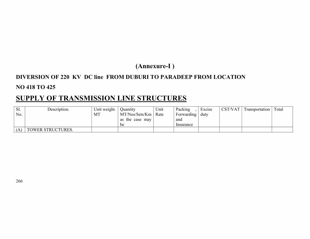
266
(Annexure-I ) DIVERSION OF 220 KV DC line FROM DUBURI TO PARADEEP FROM LOCATION
NO 418 TO 425 SUPPLY OF TRANSMISSION LINE STRUCTURES
Sl. No.
Description. Unit weight. MT
Quantity MT/Nos/Sets/Km as the case may be
Unit Rate
Packing , Forwarding and Insurance
Excise duty
CST/VAT Transportation Total
(A) TOWER STRUCTURES.
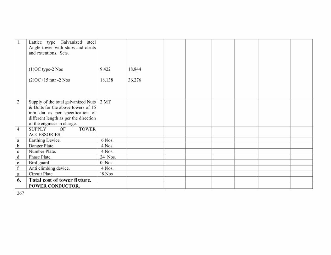
267
1. Lattice type Galvanized steel Angle tower with stubs and cleats and extentions. Sets.
(1)OC type-2 Nos (2)OC+15 mtr -2 Nos
9.422 18.138
18.844 36.276
2 Supply of the total galvanized Nuts & Bolts for the above towers of 16 mm dia as per specification of different length as per the direction of the engineer in charge.
2 MT
4 SUPPLY OF TOWER ACCESSORIES.
a Earthing Device. 6 Nos. b Danger Plate. 4 Nos. c Number Plate. 4 Nos. d Phase Plate. 24 Nos. e Bird guard 0 Nos. f Anti climbing device. 4 Nos. g Circuit Plate `8 Nos 6. Total cost of tower fixture. POWER CONDUCTOR.
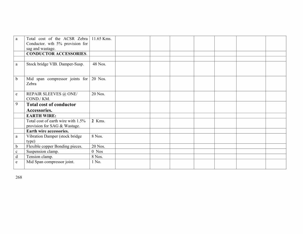
268
a Total cost of the ACSR Zebra Conductor. wth 5% provision for sag and wastage.
11.65 Kms.
CONDUCTOR ACCESSORIES. a Stock bridge VIB. Damper-Susp. 48 Nos.
b Mid span compressor joints for Zebra
20 Nos.
e REPAIR SLEEVES @ ONE/ COND./ KM.
20 Nos.
9 Total cost of conductor Accessories.
EARTH WIRE: Total cost of earth wire with 1.5%
provision for SAG & Wastage. 2 Kms.
Earth wire accessories. a Vibration Damper (stock bridge
type) 8 Nos.
b Flexible copper Bonding pieces. 20 Nos. c Suspension clamp. 0 Nos d Tension clamp. 8 Nos. e Mid Span compressor joint. 1 No.

269
10 Total cost of earth wire accessories.
INSULATORS. a 90KN Insulator (taking 5% extra
towards wastage) 117 Nos.
b 160 KN Insulator (taking 5% extra towards wastage.)
1512 Nos.
11 Total cost of the insulator. HARDWARE FITTINGS. a Single suspension Hardwares
fittings AGS Type. 8 Nos.
b Double suspension Hardware fittings AGS Type.
0 Nos.
c Single tension Hardware fittings. 0 Nos. d. Double tension Hardware fittings. 8 Nos. e Hanger 8 Nos f U-bolt 8 Nos 12 Total cost of Hardware
fittings.

270
13 Supply of MS Templates for the above type towers and their extentions of +3 mtrs and +6 mtrs as below
(a)OC+15 and OC Type-1nos
each
3.2 MT

271
Erection schedule for 418 to 425
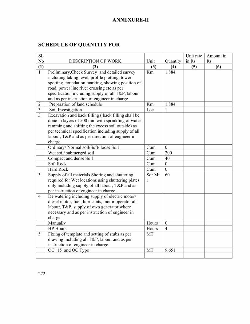
272
ANNEXURE-II SCHEDULE OF QUANTITY FOR SL No
DESCRIPTION OF WORK
Unit
Quantity
Unit rate in Rs.
Amount in Rs.
(1) (2) (3) (4) (5) (6) 1 Preliminary,Check Survey and detailed survey
including taking level, profile plotting, tower spotting, foundation marking, showing position of road, power line river crossing etc as per specification including supply of all T&P, labour and as per instruction of engineer in charge.
Km. 1.884
2 Preparation of land schedule Km 1.884 3 Soil Investigation Loc 1 3 Excavation and back filling ( back filling shall be
done in layers of 500 mm with sprinkling of water ramming and shifting the excess soil outside) as per technical specification including supply of all labour, T&P and as per direction of engineer in charge.
Ordinary/ Normal soil/Soft/ loose Soil Cum 0 Wet soil/ submerged soil Cum 200 Compact and dense Soil Cum 40 Soft Rock Cum 0 Hard Rock Cum 0 3 Supply of all materials,Shoring and shuttering
required for Wet locations using shuttering plates only including supply of all labour, T&P and as per instruction of engineer in charge.
Sqr.Mtr
60
4 De watering including supply of electric motor/ diesel motor, fuel, lubricants, motor operator all labour, T&P, supply of own generator where necessary and as per instruction of engineer in charge.
Manually Hours 0 HP Hours Hours 4 5 Fixing of template and setting of stubs as per
drawing including all T&P, labour and as per instruction of engineer in charge.
MT
OC+15 and OC Type MT 9.651

273
6. For shallow foundation (opencast) work. Providing and laying ordinary plane reinforcement concrete work of grade M-150(1:2:4) with approved quality stone chips of nominal size 12mm to 20 mm in tower foundation and coping inclusive of cost of mixing, supply of form boxes laying, curing, testing of sample cubes etc. with supply of cement , except reinforcement steel rods ,all labour and T&P conforming to relevant IS. The cooping height should be 350mm above the ground level. The surrounding area should be clear from deposited materials and damage of the land if any should be repaired before taking final measurement. (1)Cement Ratio 1 :1.5:3 (3)1:3:6
Cum Cum
400 30
7 Hoisting & fixing of insulators with required accessories, paying out position, stringing, sagging etc, of power conductor (ACSR Zebra 6 nos. conductors) and earth wire (one earth wire) with all required accessories including scaffolding for EHT, HT, LT & P&T lines, railway crossing and using own required T&P and compression jointing machine, all labour etc.
Route/ Km.
1.884

274
8 Erection of Towers: Erection of tower supper-structure complete with tightening & punching of bolts including fixing and punching of step-bolts. All the left out portion of the bolts above bottom cross arm should be riveted by using suitable hammer. Supply & painting of structure by black bituminous paints( 3 coats should to be provided) up to a height of 500 mm above the cooping. (Both the leg and bracing members to be painted). Including supply of all labour and T&P
MT
56
9 Excavation in all type of soil including rock of size 800 mm x 800 mm x 3000 mm, supply of 50 Kg common salt, 50 KG of charcoal, or coke in alternate layer after putting the earthing device, supply and putting required amount of foreign soil including supply of all labour and T&Pand HEAVY DUTY 50 mm dia, 3050 mm length TATA/JINDAL make GI Pipe earth elecvtrodes, supply, putting under grounda50 X 6 mm GI Flat of adequate length and connecting to tower and the electrode.
Nos.
6
10 Fixing of Tower Accessories such as Number Plate, danger Plate, Phase Plate etc including supply of all labour and T&P etc.
No.
4
11 Fixing of anticlimbing device. No. 4
12 Welding of Bolts & Nuts (continuous welding surround the bolts & nuts) upto peak except cross arm including supply of diesel welding generator, welding rods ,all T&P, fuel and lubricants and all labour.
Nos.
7400
13 Stringing of each section beyond normal ratio of angle tower to Tngle tower
Km 0
14 Supply of all labour, T&P, dismantling the 6 Nos ACSR Zebra conductor + 1 no earthwire, packing and returning the same to the nearest OPTCL store at Choudwar including transportation, loading and unloading
Rkm 1.38
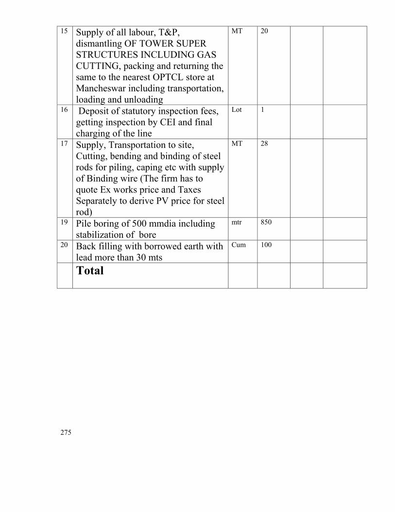
275
15 Supply of all labour, T&P, dismantling OF TOWER SUPER STRUCTURES INCLUDING GAS CUTTING, packing and returning the same to the nearest OPTCL store at Mancheswar including transportation, loading and unloading
MT 20
16 Deposit of statutory inspection fees, getting inspection by CEI and final charging of the line
Lot 1
17 Supply, Transportation to site, Cutting, bending and binding of steel rods for piling, caping etc with supply of Binding wire (The firm has to quote Ex works price and Taxes Separately to derive PV price for steel rod)
MT 28
19 Pile boring of 500 mmdia including stabilization of bore
mtr 850
20 Back filling with borrowed earth with lead more than 30 mts
Cum 100
Total
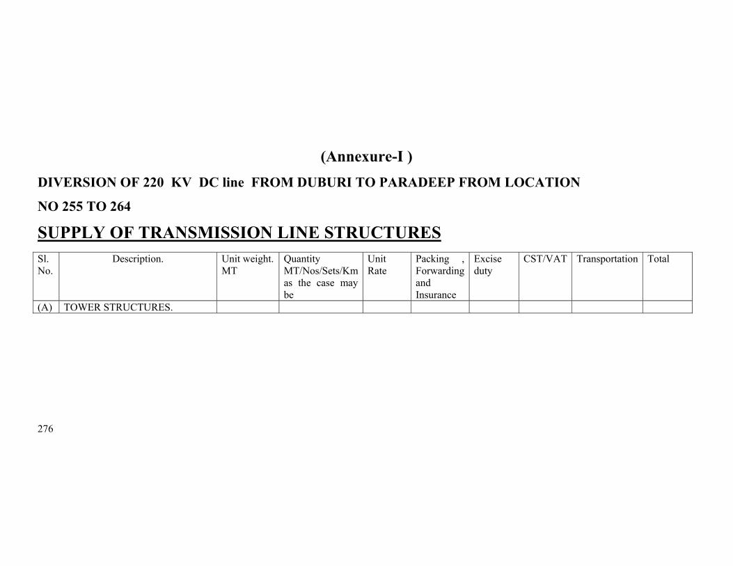
276
(Annexure-I ) DIVERSION OF 220 KV DC line FROM DUBURI TO PARADEEP FROM LOCATION
NO 255 TO 264 SUPPLY OF TRANSMISSION LINE STRUCTURES
Sl. No.
Description. Unit weight. MT
Quantity MT/Nos/Sets/Km as the case may be
Unit Rate
Packing , Forwarding and Insurance
Excise duty
CST/VAT Transportation Total
(A) TOWER STRUCTURES.
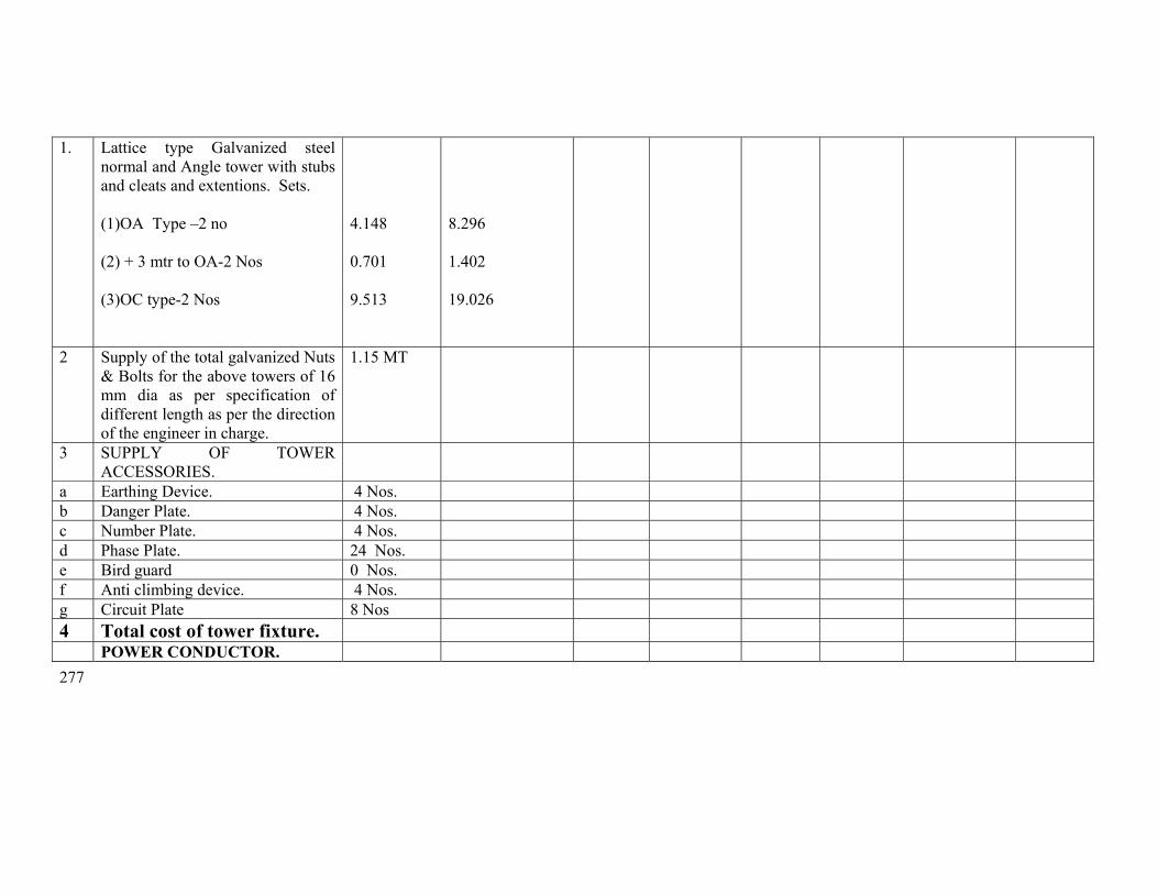
277
1. Lattice type Galvanized steel normal and Angle tower with stubs and cleats and extentions. Sets.
(1)OA Type –2 no (2) + 3 mtr to OA-2 Nos (3)OC type-2 Nos
4.148 0.701 9.513
8.296 1.402 19.026
2 Supply of the total galvanized Nuts & Bolts for the above towers of 16 mm dia as per specification of different length as per the direction of the engineer in charge.
1.15 MT
3 SUPPLY OF TOWER ACCESSORIES.
a Earthing Device. 4 Nos. b Danger Plate. 4 Nos. c Number Plate. 4 Nos. d Phase Plate. 24 Nos. e Bird guard 0 Nos. f Anti climbing device. 4 Nos. g Circuit Plate 8 Nos 4 Total cost of tower fixture. POWER CONDUCTOR.

278
a Total cost of the ACSR Zebra Conductor. wth 5% provision for sag and wastage.
15.30 Kms.
5 CONDUCTOR ACCESSORIES. a Stock bridge VIB. Damper-Susp. 48 Nos.
b Mid span compressor joints for Zebra
20 Nos.
e REPAIR SLEEVES @ ONE/ COND./ KM.
20 Nos.
Total cost of conductor Accessories.
6 EARTH WIRE: Total cost of earth wire with 1.5%
provision for SAG & Wastage. 2.6 Kms.
7 Earth wire accessories. a Vibration Damper (stock bridge
type) 8 Nos.
b Flexible copper Bonding pieces. 20 Nos. c Suspension clamp. 0 Nos d Tension clamp. 8 Nos. e Mid Span compressor joint. 4 Nos.

279
Total cost of earth wire accessories.
8 INSULATORS. a 90KN Insulator (taking 5% extra
towards wastage) 300 Nos.
b 160 KN Insulator (taking 5% extra towards wastage.)
380 Nos.
Total cost of the insulator. 9 HARDWARE FITTINGS. a Single suspension Hardwares
fittings AGS Type. 20 Nos.
b Double suspension Hardware fittings AGS Type.
0 Nos.
c Single tension Hardware fittings. 24 Nos. d. Double tension Hardware fittings. 0 Nos. e Hanger 8 Nos f U-bolt 8 Nos Total cost of Hardware
fittings.
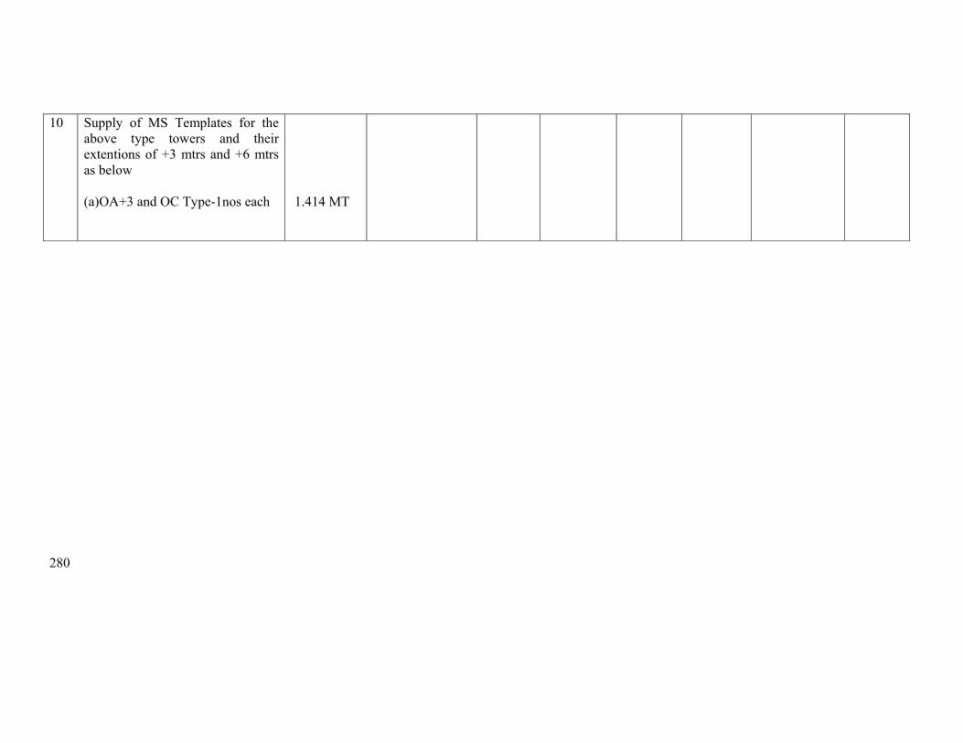
280
10 Supply of MS Templates for the above type towers and their extentions of +3 mtrs and +6 mtrs as below
(a)OA+3 and OC Type-1nos each
1.414 MT
281
Erection price schedule from 255 to 264

282
ANNEXURE-II SCHEDULE OF QUANTITY FOR SL No
DESCRIPTION OF WORK
Unit
Quantity
Unit rate in Rs.
Amount in Rs.
(1) (2) (3) (4) (5) (6) 1 Preliminary,Check Survey and detailed survey
including taking level, profile plotting, tower spotting, foundation marking, showing position of road, power line river crossing etc as per specification including supply of all T&P, labour and as per instruction of engineer in charge.
Km. 2.467
2 Preparation of land schedule Km 2.467 3 Soil Investigation Loc 1 3 Excavation and back filling ( back filling shall be
done in layers of 500 mm with sprinkling of water ramming and shifting the excess soil outside) as per technical specification including supply of all labour, T&P and as per direction of engineer in charge.
Ordinary/ Normal soil/Soft/ loose Soil Cum 0 Wet soil/ submerged soil Cum 600 Compact and dense Soil Cum 70 Soft Rock Cum 0 Hard Rock Cum 0 4 Supply of all materials,Shoring and shuttering
required for Wet locations using shuttering plates only including supply of all labour, T&P and as per instruction of engineer in charge.
Sqr.Mtr
660
5 De watering including supply of electric motor/ diesel motor, fuel, lubricants, motor operator all labour, T&P, supply of own generator where necessary and as per instruction of engineer in charge.
Manually Hours 0 HP Hours Hours 4 6 Fixing of template and setting of stubs as per
drawing including all T&P, labour and as per instruction of engineer in charge.
MT
OA, and OC Type MT 3.152

283
7. For shallow foundation (opencast) work. Providing and laying ordinary plane reinforcement concrete work of grade M-150(1:2:4) with approved quality stone chips of nominal size 12mm to 20 mm in tower foundation and coping inclusive of cost of mixing, supply of form boxes laying, curing, testing of sample cubes etc. with supply of cement , except reinforcement steel rods ,all labour and T&P conforming to relevant IS. The cooping height should be 350mm above the ground level. The surrounding area should be clear from deposited materials and damage of the land if any should be repaired before taking final measurement. (1)Cement Ratio 1 :2:4 (3)1:3:6
Cum Cum
112 1
8 Hoisting & fixing of insulators with required accessories, paying out position, stringing, sagging etc, of power conductor (ACSR Zebra 6 nos. conductors) and earth wire (one earth wire) with all required accessories including scaffolding for EHT, HT, LT & P&T lines, railway crossing and using own required T&P and compression jointing machine, all labour etc.
Route/ Km.
1.225
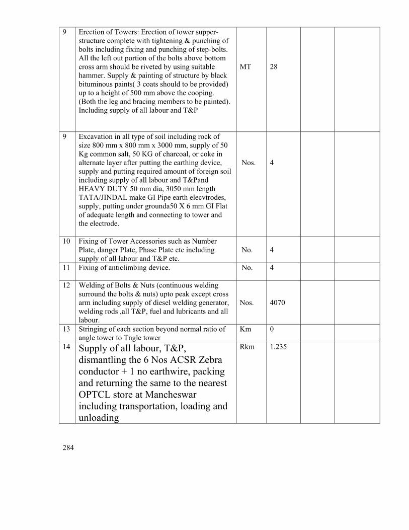
284
9 Erection of Towers: Erection of tower supper-structure complete with tightening & punching of bolts including fixing and punching of step-bolts. All the left out portion of the bolts above bottom cross arm should be riveted by using suitable hammer. Supply & painting of structure by black bituminous paints( 3 coats should to be provided) up to a height of 500 mm above the cooping. (Both the leg and bracing members to be painted). Including supply of all labour and T&P
MT
28
9 Excavation in all type of soil including rock of size 800 mm x 800 mm x 3000 mm, supply of 50 Kg common salt, 50 KG of charcoal, or coke in alternate layer after putting the earthing device, supply and putting required amount of foreign soil including supply of all labour and T&Pand HEAVY DUTY 50 mm dia, 3050 mm length TATA/JINDAL make GI Pipe earth elecvtrodes, supply, putting under grounda50 X 6 mm GI Flat of adequate length and connecting to tower and the electrode.
Nos.
4
10 Fixing of Tower Accessories such as Number Plate, danger Plate, Phase Plate etc including supply of all labour and T&P etc.
No.
4
11 Fixing of anticlimbing device. No. 4
12 Welding of Bolts & Nuts (continuous welding surround the bolts & nuts) upto peak except cross arm including supply of diesel welding generator, welding rods ,all T&P, fuel and lubricants and all labour.
Nos.
4070
13 Stringing of each section beyond normal ratio of angle tower to Tngle tower
Km 0
14 Supply of all labour, T&P, dismantling the 6 Nos ACSR Zebra conductor + 1 no earthwire, packing and returning the same to the nearest OPTCL store at Mancheswar including transportation, loading and unloading
Rkm 1.235
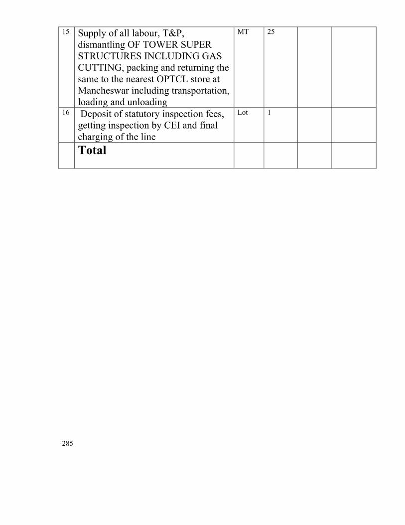
285
15 Supply of all labour, T&P, dismantling OF TOWER SUPER STRUCTURES INCLUDING GAS CUTTING, packing and returning the same to the nearest OPTCL store at Mancheswar including transportation, loading and unloading
MT 25
16 Deposit of statutory inspection fees, getting inspection by CEI and final charging of the line
Lot 1
Total

286
(Annexure-I ) DIVERSION OF 220 KV DC line FROM DUBURI TO PARADEEP FROM LOCATION
NO 151 TO 159 SUPPLY OF TRANSMISSION LINE STRUCTURES
Sl. No.
Description. Unit weight. MT
Quantity MT/Nos/Sets/Km as the case may be
Unit Rate
Packing , Forwarding and Insurance
Excise duty
CST/VAT Transportation Total
(A) TOWER STRUCTURES.
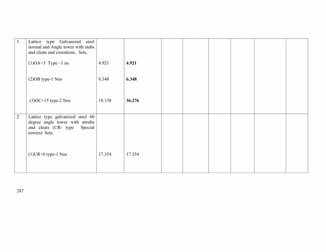
287
1. Lattice type Galvanized steel normal and Angle tower with stubs and cleats and extentions. Sets.
(1)OA+3 Type –1 no (2)OB type-1 Nos (3)OC+15 type-2 Nos
4.921 6.348 18.138
4.921 6.348 36.276
2 Lattice type galvanized steel 60 degree angle tower with sttrubs and cleats (UR- type Special towers) Sets.
(1)UR+6 type-1 Nos
17.354
17.354
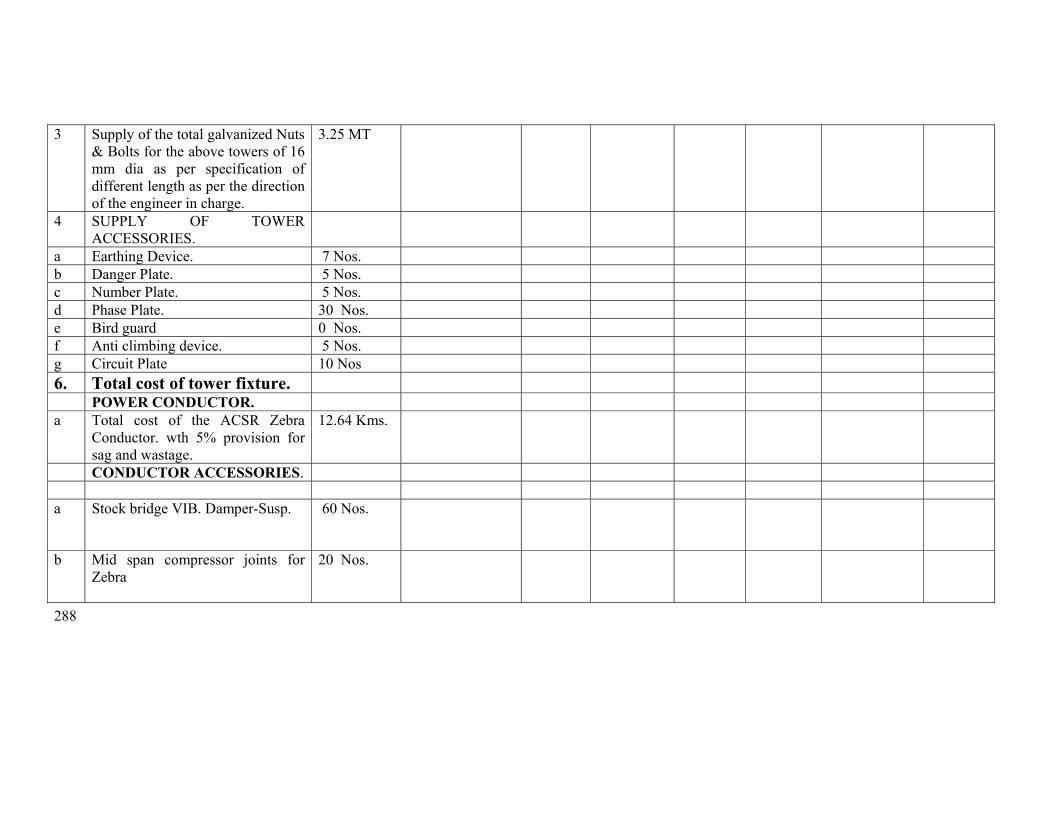
288
3 Supply of the total galvanized Nuts & Bolts for the above towers of 16 mm dia as per specification of different length as per the direction of the engineer in charge.
3.25 MT
4 SUPPLY OF TOWER ACCESSORIES.
a Earthing Device. 7 Nos. b Danger Plate. 5 Nos. c Number Plate. 5 Nos. d Phase Plate. 30 Nos. e Bird guard 0 Nos. f Anti climbing device. 5 Nos. g Circuit Plate 10 Nos 6. Total cost of tower fixture. POWER CONDUCTOR. a Total cost of the ACSR Zebra
Conductor. wth 5% provision for sag and wastage.
12.64 Kms.
CONDUCTOR ACCESSORIES. a Stock bridge VIB. Damper-Susp. 60 Nos.
b Mid span compressor joints for Zebra
20 Nos.
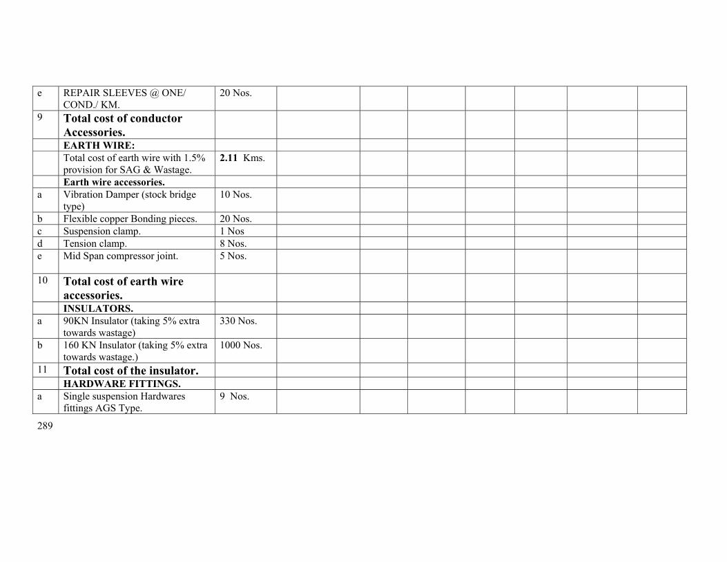
289
e REPAIR SLEEVES @ ONE/ COND./ KM.
20 Nos.
9 Total cost of conductor Accessories.
EARTH WIRE: Total cost of earth wire with 1.5%
provision for SAG & Wastage. 2.11 Kms.
Earth wire accessories. a Vibration Damper (stock bridge
type) 10 Nos.
b Flexible copper Bonding pieces. 20 Nos. c Suspension clamp. 1 Nos d Tension clamp. 8 Nos. e Mid Span compressor joint. 5 Nos.
10 Total cost of earth wire accessories.
INSULATORS. a 90KN Insulator (taking 5% extra
towards wastage) 330 Nos.
b 160 KN Insulator (taking 5% extra towards wastage.)
1000 Nos.
11 Total cost of the insulator. HARDWARE FITTINGS. a Single suspension Hardwares
fittings AGS Type. 9 Nos.
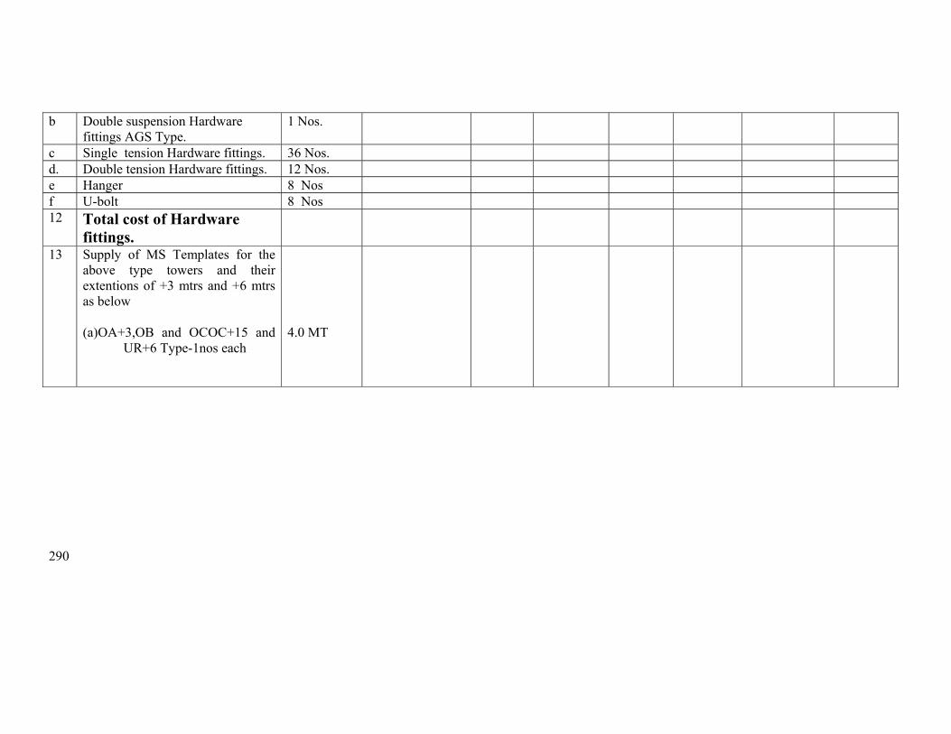
290
b Double suspension Hardware fittings AGS Type.
1 Nos.
c Single tension Hardware fittings. 36 Nos. d. Double tension Hardware fittings. 12 Nos. e Hanger 8 Nos f U-bolt 8 Nos 12 Total cost of Hardware
fittings.
13 Supply of MS Templates for the above type towers and their extentions of +3 mtrs and +6 mtrs as below
(a)OA+3,OB and OCOC+15 and
UR+6 Type-1nos each
4.0 MT
291
Erection price schedule from 151 to 159

292
ANNEXURE-II SCHEDULE OF QUANTITY FOR SL No
DESCRIPTION OF WORK
Unit
Quantity
Unit rate in Rs.
Amount in Rs.
(1) (2) (3) (4) (5) (6) 1 Preliminary,Check Survey and detailed survey
including taking level, profile plotting, tower spotting, foundation marking, showing position of road, power line river crossing etc as per specification including supply of all T&P, labour and as per instruction of engineer in charge.
Km. 2.045
2 Preparation of land schedule Km 2.045 3 Soil Investigation Loc 1 3 Excavation and back filling ( back filling shall be
done in layers of 500 mm with sprinkling of water ramming and shifting the excess soil outside) as per technical specification including supply of all labour, T&P and as per direction of engineer in charge.
Ordinary/ Normal soil/Soft/ loose Soil Cum 0 Wet soil/ submerged soil Cum 1000 Compact and dense Soil Cum 690 Soft Rock Cum 0 Hard Rock Cum 0 3 Supply of all materials,Shoring and shuttering
required for Wet locations using shuttering plates only including supply of all labour, T&P and as per instruction of engineer in charge.
Sqr.Mtr
850
4 De watering including supply of electric motor/ diesel motor, fuel, lubricants, motor operator all labour, T&P, supply of own generator where necessary and as per instruction of engineer in charge.
Manually Hours 0 HP Hours Hours 5 5 Fixing of template and setting of stubs as per
drawing including all T&P, labour and as per instruction of engineer in charge.
MT
OA, OB OC and UR Type MT 8

293
6. For shallow foundation (opencast) work. Providing and laying ordinary plane reinforcement concrete work of grade M-150(1:2:4) with approved quality stone chips of nominal size 12mm to 20 mm in tower foundation and coping inclusive of cost of mixing, supply of form boxes laying, curing, testing of sample cubes etc. with supply of cement , except reinforcement steel rods ,all labour and T&P conforming to relevant IS. The cooping height should be 350mm above the ground level. The surrounding area should be clear from deposited materials and damage of the land if any should be repaired before taking final measurement. (1)Cement Ratio 1 :2:4 (3)1:3:6
Cum Cum
443 1
7 Hoisting & fixing of insulators with required accessories, paying out position, stringing, sagging etc, of power conductor (ACSR Zebra 6 nos. conductors) and earth wire (one earth wire) with all required accessories including scaffolding for EHT, HT, LT & P&T lines, railway crossing and using own required T&P and compression jointing machine, all labour etc.
Route/ Km.
3
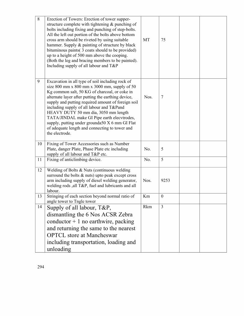
294
8 Erection of Towers: Erection of tower supper-structure complete with tightening & punching of bolts including fixing and punching of step-bolts. All the left out portion of the bolts above bottom cross arm should be riveted by using suitable hammer. Supply & painting of structure by black bituminous paints( 3 coats should to be provided) up to a height of 500 mm above the cooping. (Both the leg and bracing members to be painted). Including supply of all labour and T&P
MT
75
9 Excavation in all type of soil including rock of size 800 mm x 800 mm x 3000 mm, supply of 50 Kg common salt, 50 KG of charcoal, or coke in alternate layer after putting the earthing device, supply and putting required amount of foreign soil including supply of all labour and T&Pand HEAVY DUTY 50 mm dia, 3050 mm length TATA/JINDAL make GI Pipe earth elecvtrodes, supply, putting under grounda50 X 6 mm GI Flat of adequate length and connecting to tower and the electrode.
Nos.
7
10 Fixing of Tower Accessories such as Number Plate, danger Plate, Phase Plate etc including supply of all labour and T&P etc.
No.
5
11 Fixing of anticlimbing device. No. 5
12 Welding of Bolts & Nuts (continuous welding surround the bolts & nuts) upto peak except cross arm including supply of diesel welding generator, welding rods ,all T&P, fuel and lubricants and all labour.
Nos.
9253
13 Stringing of each section beyond normal ratio of angle tower to Tngle tower
Km 0
14 Supply of all labour, T&P, dismantling the 6 Nos ACSR Zebra conductor + 1 no earthwire, packing and returning the same to the nearest OPTCL store at Mancheswar including transportation, loading and unloading
Rkm 3
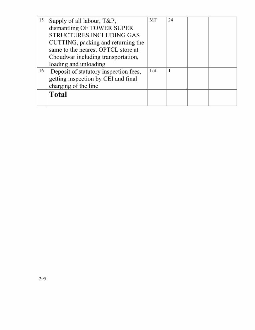
295
15 Supply of all labour, T&P, dismantling OF TOWER SUPER STRUCTURES INCLUDING GAS CUTTING, packing and returning the same to the nearest OPTCL store at Choudwar including transportation, loading and unloading
MT 24
16 Deposit of statutory inspection fees, getting inspection by CEI and final charging of the line
Lot 1
Total
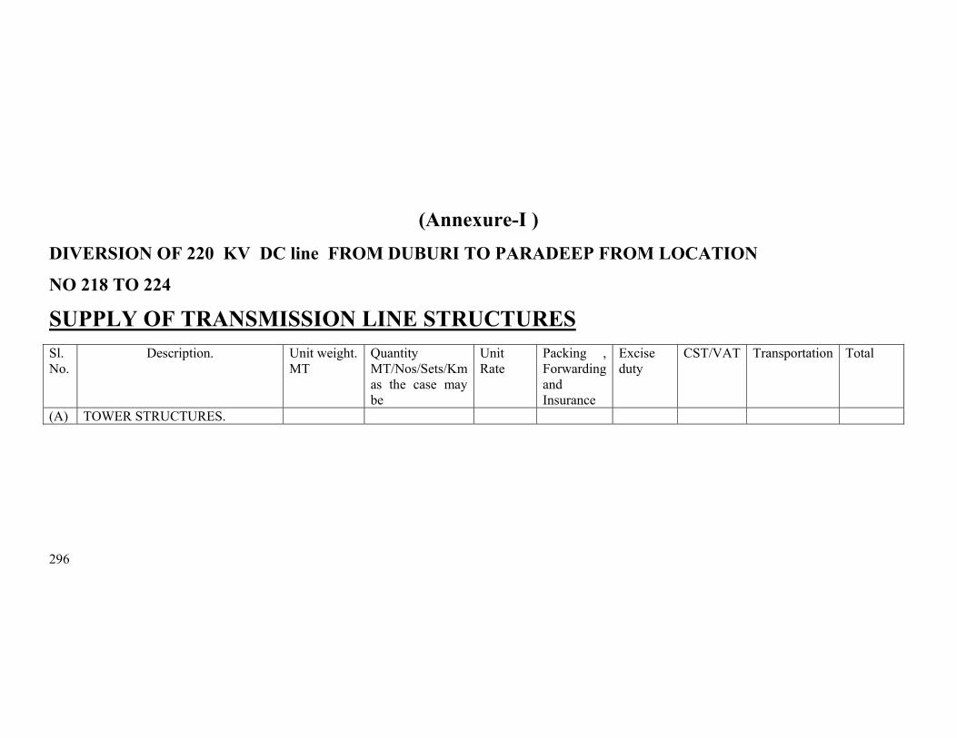
296
(Annexure-I ) DIVERSION OF 220 KV DC line FROM DUBURI TO PARADEEP FROM LOCATION
NO 218 TO 224 SUPPLY OF TRANSMISSION LINE STRUCTURES
Sl. No.
Description. Unit weight. MT
Quantity MT/Nos/Sets/Km as the case may be
Unit Rate
Packing , Forwarding and Insurance
Excise duty
CST/VAT Transportation Total
(A) TOWER STRUCTURES.
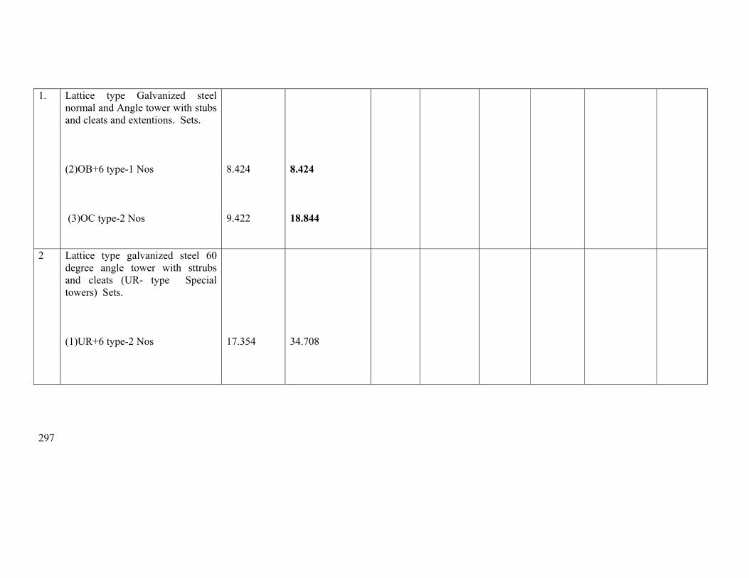
297
1. Lattice type Galvanized steel normal and Angle tower with stubs and cleats and extentions. Sets.
(2)OB+6 type-1 Nos (3)OC type-2 Nos
8.424 9.422
8.424 18.844
2 Lattice type galvanized steel 60 degree angle tower with sttrubs and cleats (UR- type Special towers) Sets.
(1)UR+6 type-2 Nos
17.354
34.708
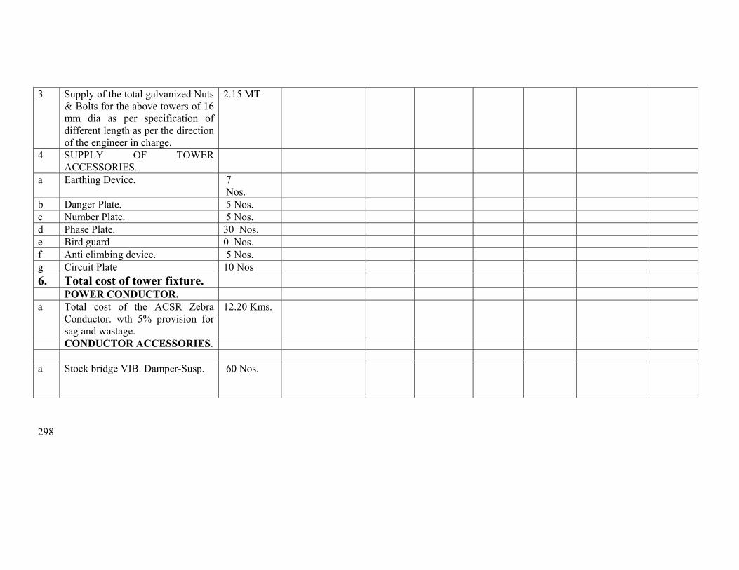
298
3 Supply of the total galvanized Nuts & Bolts for the above towers of 16 mm dia as per specification of different length as per the direction of the engineer in charge.
2.15 MT
4 SUPPLY OF TOWER ACCESSORIES.
a Earthing Device. 7 Nos.
b Danger Plate. 5 Nos. c Number Plate. 5 Nos. d Phase Plate. 30 Nos. e Bird guard 0 Nos. f Anti climbing device. 5 Nos. g Circuit Plate 10 Nos 6. Total cost of tower fixture. POWER CONDUCTOR. a Total cost of the ACSR Zebra
Conductor. wth 5% provision for sag and wastage.
12.20 Kms.
CONDUCTOR ACCESSORIES. a Stock bridge VIB. Damper-Susp. 60 Nos.
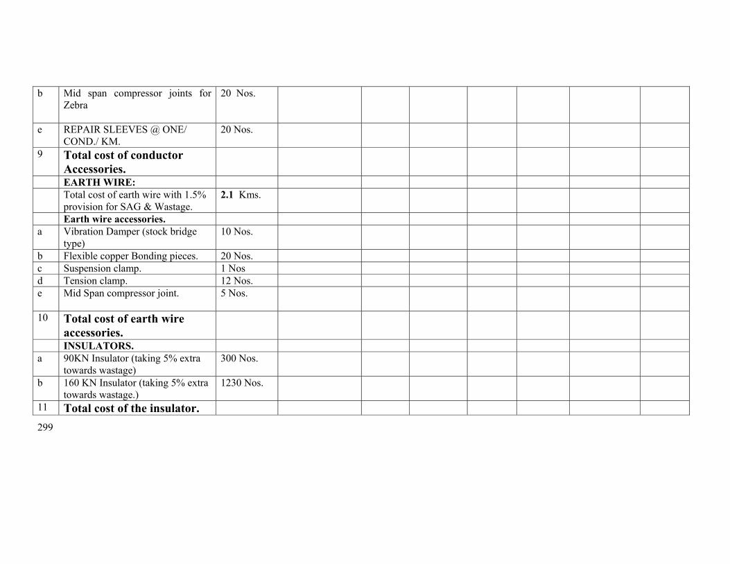
299
b Mid span compressor joints for Zebra
20 Nos.
e REPAIR SLEEVES @ ONE/ COND./ KM.
20 Nos.
9 Total cost of conductor Accessories.
EARTH WIRE: Total cost of earth wire with 1.5%
provision for SAG & Wastage. 2.1 Kms.
Earth wire accessories. a Vibration Damper (stock bridge
type) 10 Nos.
b Flexible copper Bonding pieces. 20 Nos. c Suspension clamp. 1 Nos d Tension clamp. 12 Nos. e Mid Span compressor joint. 5 Nos.
10 Total cost of earth wire accessories.
INSULATORS. a 90KN Insulator (taking 5% extra
towards wastage) 300 Nos.
b 160 KN Insulator (taking 5% extra towards wastage.)
1230 Nos.
11 Total cost of the insulator.
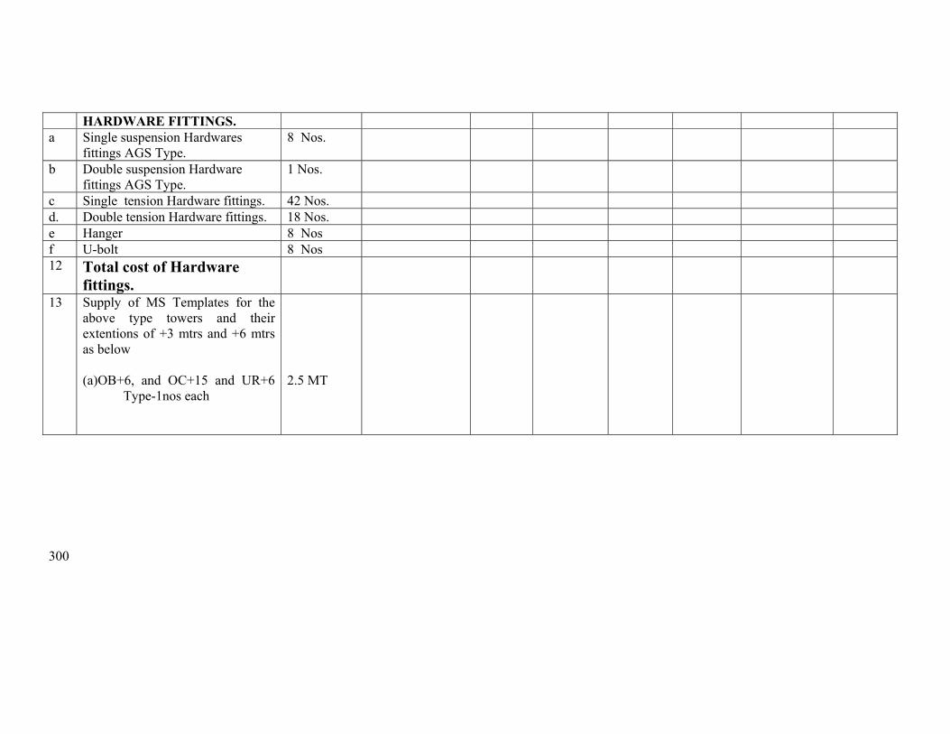
300
HARDWARE FITTINGS. a Single suspension Hardwares
fittings AGS Type. 8 Nos.
b Double suspension Hardware fittings AGS Type.
1 Nos.
c Single tension Hardware fittings. 42 Nos. d. Double tension Hardware fittings. 18 Nos. e Hanger 8 Nos f U-bolt 8 Nos 12 Total cost of Hardware
fittings.
13 Supply of MS Templates for the above type towers and their extentions of +3 mtrs and +6 mtrs as below
(a)OB+6, and OC+15 and UR+6
Type-1nos each
2.5 MT

301
Erection price schedule from 218 to 224

302
ANNEXURE-II SCHEDULE OF QUANTITY FOR SL No
DESCRIPTION OF WORK
Unit
Quantity
Unit rate in Rs.
Amount in Rs.
(1) (2) (3) (4) (5) (6) 1 Preliminary,Check Survey and detailed survey
including taking level, profile plotting, tower spotting, foundation marking, showing position of road, power line river crossing etc as per specification including supply of all T&P, labour and as per instruction of engineer in charge.
Km. 1.974
2 Preparation of land schedule Km 1.974 3 Soil Investigation Loc 1 3 Excavation and back filling ( back filling shall be
done in layers of 500 mm with sprinkling of water ramming and shifting the excess soil outside) as per technical specification including supply of all labour, T&P and as per direction of engineer in charge.
Ordinary/ Normal soil/Soft/ loose Soil Cum 0 Wet soil/ submerged soil Cum 1100 Compact and dense Soil Cum 900 Soft Rock Cum 0 Hard Rock Cum 0 3 Supply of all materials,Shoring and shuttering
required for Wet locations using shuttering plates only including supply of all labour, T&P and as per instruction of engineer in charge.
Sqr.Mtr
1000
4 De watering including supply of electric motor/ diesel motor, fuel, lubricants, motor operator all labour, T&P, supply of own generator where necessary and as per instruction of engineer in charge.
Manually Hours 0 HP Hours Hours 5 5 Fixing of template and setting of stubs as per
drawing including all T&P, labour and as per instruction of engineer in charge.
MT
OB OC and UR Type MT 6

303
6. For shallow foundation (opencast) work. Providing and laying ordinary plane reinforcement concrete work of grade M-150(1:2:4) with approved quality stone chips of nominal size 12mm to 20 mm in tower foundation and coping inclusive of cost of mixing, supply of form boxes laying, curing, testing of sample cubes etc. with supply of cement , except reinforcement steel rods ,all labour and T&P conforming to relevant IS. The cooping height should be 350mm above the ground level. The surrounding area should be clear from deposited materials and damage of the land if any should be repaired before taking final measurement. (1)Cement Ratio 1 :2:4 (3)1:3:6
Cum Cum
540 1
7 Hoisting & fixing of insulators with required accessories, paying out position, stringing, sagging etc, of power conductor (ACSR Zebra 6 nos. conductors) and earth wire (one earth wire) with all required accessories including scaffolding for EHT, HT, LT & P&T lines, railway crossing and using own required T&P and compression jointing machine, all labour etc.
Route/ Km.
2.5
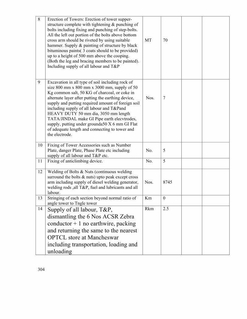
304
8 Erection of Towers: Erection of tower supper-structure complete with tightening & punching of bolts including fixing and punching of step-bolts. All the left out portion of the bolts above bottom cross arm should be riveted by using suitable hammer. Supply & painting of structure by black bituminous paints( 3 coats should to be provided) up to a height of 500 mm above the cooping. (Both the leg and bracing members to be painted). Including supply of all labour and T&P
MT
70
9 Excavation in all type of soil including rock of size 800 mm x 800 mm x 3000 mm, supply of 50 Kg common salt, 50 KG of charcoal, or coke in alternate layer after putting the earthing device, supply and putting required amount of foreign soil including supply of all labour and T&Pand HEAVY DUTY 50 mm dia, 3050 mm length TATA/JINDAL make GI Pipe earth elecvtrodes, supply, putting under grounda50 X 6 mm GI Flat of adequate length and connecting to tower and the electrode.
Nos.
7
10 Fixing of Tower Accessories such as Number Plate, danger Plate, Phase Plate etc including supply of all labour and T&P etc.
No.
5
11 Fixing of anticlimbing device. No. 5
12 Welding of Bolts & Nuts (continuous welding surround the bolts & nuts) upto peak except cross arm including supply of diesel welding generator, welding rods ,all T&P, fuel and lubricants and all labour.
Nos.
8745
13 Stringing of each section beyond normal ratio of angle tower to Tngle tower
Km 0
14 Supply of all labour, T&P, dismantling the 6 Nos ACSR Zebra conductor + 1 no earthwire, packing and returning the same to the nearest OPTCL store at Mancheswar including transportation, loading and unloading
Rkm 2.5

305
15 Supply of all labour, T&P, dismantling OF TOWER SUPER STRUCTURES INCLUDING GAS CUTTING, packing and returning the same to the nearest OPTCL store at Choudwar including transportation, loading and unloading
MT 15
16 Deposit of statutory inspection fees, getting inspection by CEI and final charging of the line
Lot 1
Total

1