Embed Size (px)
Citation preview

8/8/2019 EHS Env Guidelines
http://slidepdf.com/reader/full/ehs-env-guidelines 1/155

8/8/2019 EHS Env Guidelines
http://slidepdf.com/reader/full/ehs-env-guidelines 2/155

8/8/2019 EHS Env Guidelines
http://slidepdf.com/reader/full/ehs-env-guidelines 3/155

8/8/2019 EHS Env Guidelines
http://slidepdf.com/reader/full/ehs-env-guidelines 4/155

8/8/2019 EHS Env Guidelines
http://slidepdf.com/reader/full/ehs-env-guidelines 5/155
PCFC-EG#1 Page 2 of 4 Revised:23/04/03
(vii) All abrasive blasters operating in PCFC shall use a recyclable non-metallurgical abrasivematerial.
b. Gaseous Emissions EmissionLimits
Amines - total amine 5 p.p.m v/v- trimethylamine 1 p.p.m v/v
Asphalt fumes 5 mg/3
The waste gases from industrial processes are often a mixture of acid gases and whilst it is notpracticable to measure each component separately, it is convenient to measure the total acidity andto express it as sulphur trioxide (see below table) as a basis for comparison.
1.4 SOURCE EMISSION CRITERIA - AIR POLLUTANTS
SUBSTANCE SYMBOL SOURCESEMISSION LIMITS
(mg/Nm 3) Visible Emissions Combustion sources
Other sources250
noneCarbon Monoxide CO ll sources 500
Nitrogen Oxides(Expressed as nitrogendioxide)
NOxCombustion sources
Material producingindustries
Other sources
Gas fuel-350Liquid fuel-500
1500
200Sulphur Dioxide SO 2 Combustion sources
Material producingindustries
Other sources
5002000
1000Sulphur Trioxide
Including Sulphuric Acid Mist(Expressed as sulphur trioxide)
SO 3 Material producing
industriesOther sources
150
50Total Suspended Particles
TSPCombustion sources
Cement IndustriesOther sources
25050
150mmonia and Ammonium
Compounds (expressed asammonia)
NH3 Material producingindustries
Other sources
50
10Benzene C 6H6 ll sources 5
Iron Fe Iron & Steel foundries 100
Lead and its compounds(expressed as lead) Pb ll sources 5
Antimony and its Compounds(Expressed as antimony)
Sb Material producingindustries
Other sources
5
1rsenic and its Compounds
(expressed as arsenic) As ll sources 1
Cadmium and its compounds(expressed as cadmium)
Cd ll sources 1
Mercury and its compounds(expressed as mercury)
Hg ll sources 0.5
Nickel and its compounds(expressed as nickel)
Ni ll sources 1

8/8/2019 EHS Env Guidelines
http://slidepdf.com/reader/full/ehs-env-guidelines 6/155
PCFC-EG#1 Page 3 of 4 Revised:23/04/03
Copper and its compounds(expressed as copper)
Cu ll sources 5
Hydrogen Sulphide H 2S ll sources 5Chloride Cl Chlorine Works
Other sources20010
Hydrogen Chloride HCI Chlorine WorksOther sources
20020
Hydrogen Fluoride HF ll sources 2Silicon Fluoride SiF 4 ll sources 10
Fluoride and its CompoundsIncluding HF & SiF 4
(expressed fluoride)
F- luminum smeltersOther sources
2050
Formaldehyde CH 20 Material producingindustries
Other sources
20
2Carbon C node productionWaste incineration
25050
Total Volatile Organic Compounds
(expressed as total organiccarbon -TOC)
VOC ll sources 20
Dioxins and Furans ll sources 1 ng TEQ/m 3
Notes:
1. The concentration of any substance specified in the first column emitted from any source specified inthe third column shall not at any point before admixture with air, smoke or other gases, exceed thelimits specified in the fourth column.
2. “mg” means milligram;3. “ng” means nanogram.4. “Nm 3” means normal cubic meter, being that amount of gas which when dry, occupies a cubic meter
at a temperature of 25 degree Centigrade and at an absolute pressure of 760 millimeters of mercury(1 atm);
5. The limit of “Visible Emission” does not apply to emission of water vapour and a reasonable periodfor cold start up, shutdown or emergency operation.
6. The measurement for “Total Suspended Particles (TSP)’’ emitted from combustion sources should be@12% reference CO 2.
7. The total concentration of the heavy metals (Pb, Cd, Ni, Hg, Cu, As & Sb) must not exceed 5 mg/Nm 3.
8. VOC limit is for unburned hydrocarbons (uncontrolled).9. The emission limits for all the substances exclude “Dioxins and Furans” conducted as a daily average
value.10. TEQ means “Total Equivalent Quantity.” Dioxins and Furans”. Average values shall be measured
over a sample period of a minimum of 6 hours and a maximum of 8 hours. The emission limit valuerefers to the total concentration of dioxins and furans calculated using the concept of toxicequivalence (Refer to PCFC-ER, 3 rd Edition for more details).
For more information please contact Environment, Health and Safety – Free Zone(EHS-FZ) Department on Tel# 8040275, Fax # 8817023 or P.O.Box17000, Dubai.

8/8/2019 EHS Env Guidelines
http://slidepdf.com/reader/full/ehs-env-guidelines 7/155
PCFC-EG#1 Page 4 of 4 Revised:23/04/03
ENVIRONMENTAL GUIDELINE No.2
LARGE BOILERS AND FURNACES
2.1 GENERAL GUIDELINES
(i) These notes apply to works in which solid, liquid or gaseous fuel is burned, having a heat input equalto or greater than 30 megawatts (100 million BTU/h). A guide for boiler installation (available fromEHS Dept. separately) should be used as a reference.
A. Sampling, Measurement Of Emissions And Monitoring
(i) Emissions of sulphur dioxide, nitrogen oxides and particulate matter, including smoke, from eachboiler or furnace shall be monitored continuously and shall be displayed on a meter visible tooperating staff. Sampling ports and ladder/flanges facilities to be made available for monitoring.
(ii) The accepted form of particulate emission monitoring is by optical density measurements for the fineparticles and by a gravimetric method for coarse particles.
(iii) Zero and calibration checks on monitoring instruments shall be carried out by the company. Thereference test method for particulates is by the procedure of British Standard 3405:1983.
(iv) All limit values in these notes are expressed as being at the reference conditions of 30 oC and 1 barand a standard of 12 percent CO 2 in the waste combustion gases.
B. Emission Limits And Controls
(i) For oil-fired plant, sulphur dioxide removal equipment shall be installed with a removal efficiency of not less than 99.9 per cent.
(ii) The design of the combustion system on oil-fired plant shall aim to limit the emission of nitric oxides tothe air to a concentration not exceeding 500 mg/m 3 in normal operation for oil-fired.
(iii) The concentration of particulate matter in emissions to air shall not exceed 500mg/m 3 as a 2-houraverage.
(iv) Emissions in normal operation, shall be free from visible smoke and in any case shall not exceed250 mg/ m 3.
(v) For non-combustion plant, the concentration of particulate matter in emissions to air from thehandling, crushing or screening of solid materials used in or produced by the combustion processshall not exceed 250 g/m 3.
C. Operational Controls
(i) Means for preventing the emission of acid soot from oil-firing shall be operated continuously and thetemperature of the gases in the chimney shall normally be maintained at not less than 150 oC.
(ii) Chimneys, flues and the duct work leading to the chimney shall be insulated to prevent liquidcondensation on internal surfaces.

8/8/2019 EHS Env Guidelines
http://slidepdf.com/reader/full/ehs-env-guidelines 8/155
PCFC-EG#2 Page 1 of 2 Revised:23/04/03
D. Chimneys
(i)
Chimney heights shall be assessed on the basis of estimated ground-level concentrations of theresidual gases and taking account of local circumstances and recognized air quality standards orcriteria.
(ii) The efflux velocity of the emitted hot, dry gases shall not be less than 15 m/s at maximum continuousrating for boilers or furnaces from 30 to 700 MW thermal rating, and not less than 18/m/s forcombustion plant rated above 700 MW.
(iii) For non-combustion processes, chimneys shall normally be designed for an efflux velocity of not lessthan 15 m/s, but where a wet method of arrestment has been used, the velocity in the chimney shallnot exceed 9 m/s to avoid droplet entrainment from the chimney surface.
2.2 TECHNICAL GUIDELINES FOR STEAM BOILER INSTALLATION
Prior to any steam boiler installation in the Free Zone, the following Health, Safety and EnvironmentGuidelines are to be fulfilled:
(i) Details of the steam boiler including capacity, fuel type (with sulphur content < 1%), fuel rate, fuelsulphur content etc. have to be provided.
(ii) Boiler room height and any adjacent building height to be provided. Boiler chimney heightcalculation will be provided by PCFC to the client.
(iii) The fuel tank should be bunded with impervious bund wall including the bund floor. The sameshould be designed to confine fuel of 110% fuel tank capacity and the underground bund area to belined with proper PVC lining. Details of the bund wall volume calculation and design should beprovided.
(iv) Proper drainage facility should be provided for the boiler condensate and blow down to PCFCsatisfaction, away from the domestic drainage of the facility. A detailed drawing in this regard shouldbe provided.
a. Conditions mentioned under the title ‘Large Boilers and Furnaces’ should be fulfilled andacknowledged.
b. Proper sampling point to be provided on the chimney for emission quality checks.
For more information please contact Environment, Health and Safety – Free Zone(EHS-FZ) Department on Tel# 8040275, Fax # 8817023 or P.O.Box17000, Dubai.
PCFC-EG#2 Page 2 of 2 Revised:23/04/03

8/8/2019 EHS Env Guidelines
http://slidepdf.com/reader/full/ehs-env-guidelines 9/155
ENVIRONMENTAL GUIDELINE No.3
CHEMICAL FERTILIZER WORKS
1 INTRODUCTION
These notes apply to processes for the manufacture of superphosphate, phosphoric acid, ammoniumnitrate and ammonium phosphate, the granulation of compound fertilizer and the production of complete fertilizer mixtures by melt granulation or prilling.
2 SAMPLING, MEASUREMENT OF EMISSIONS AND MONITORING
The tests normally carried out are for total acidity and hydrogen chloride, ammonia, hydrogensulphide, fluoride and particulates, depending on what is being processed at the time of sampling.
3 EMISSION LIMITS AND CONTROLS A Phosphate Rock Processing
i. All emissions to the air shall be substantially free from persistent mist or fume, and free fromdroplets.
ii. The concentration of particulate matter in emissions to the air from phosphate rock grinding shallnot exceed 250 mg/m 3
B Superphosphate and Phosphoric Acid Plant
i. The total acidity of all process gases emitted to the air shall not exceed 150 mg/m 3, expressed assulphur trioxide.
ii. The hydrogen sulphide concentration in all process gases shall not exceed 5 p.p.m v/v.iii. Waste or recovered acids likely to cause the emission of odorous substances shall not be used
without prior evaluation and agreement of the Authority.
C Granulation and Prilling Plant
i. The concentration of particulate matter shall not exceed 150 mg/m 3.
ii. The concentration of hydrogen chloride shall not exceed 200 mg/m 3.
iii. The concentration of ammonia (free) shall not exceed 50 mg/m 3 to meet 2 ppm ambient criterion
iv. The concentration of fluorides (as HF) shall not exceed 2 mg/m 3.
v. VOCs should be removed/incinerated 99.9% to ensure maximum emission of 20 mg/ m 3.
D Ammonium Nitrate
i. The concentration of free ammonia from prilling plants shall not exceed 10 p.p.m v/v.
ii. The concentration of free ammonia from neutralisers and evaporator shall not exceed 50 p.p.m. v/v.
PCFC-EG#3 Page 1 of 2 Revised:23/04/03

8/8/2019 EHS Env Guidelines
http://slidepdf.com/reader/full/ehs-env-guidelines 10/155
iii. The concentration of particulate matter from evaporators, prilling towers and melt granulationplants shall not exceed 150 mg/m 3.
iv. The concentration of particulate matter from coolers and dryers, and from other containedemissions shall not exceed 150 mg/m 3.
E Ammonium Phosphate
i. The concentration of free ammonia shall not exceed 10 p.p.m v/v.
ii. The concentration of fluoride shall not exceed 20 mg/m 3 expressed as hydrogen fluoride.
iii. The concentration of particulate matter from all contained sources shall not exceed 150 mg/m 3.
F Operational Controls
i. Emissions from rock grinding, evolution of acid gases from dissolving plant and emissions fromgranule preparation vessels, dryers and coolers, shall be contained and ducted to a suitabletreatment plant acceptable to the Authority to meet the limit values above.
ii. Inlet and outlet gas temperatures on granulation plants shall be continuously monitored toprevent decomposition of the materials. Where ammonium nitrate is used, provision shall bemade for quenching any exothermic decomposition occurring in the dryer. Measures shall alsobe taken to prevent the possibility of unburnt fuel entering the dryer.
iii. It is preferable that ammonium nitrate neutralisers should be fully enclosed with no direct vent toair, but if this is not practicable then suitable treatment equipment shall be installed to meet thelimit values in above paragraphs. Total condensation evaporators are preferred to emissiontreatment plant.
G Material Handling and Storage
i. Stocks of dusty material shall be stored under cover to prevent wind-whipping. Loading to andfrom stockpiles shall be carried out so as to minimize airborne dust.
ii.
Storage silos for dusty material shall be vented to air through suitable equipment to prevent dustemissions.
iii. All handling, transport and processing of dusty materials shall be carried out in a manner whichgives rise to no significant visible emission.
iv. The storage and handling of liquids shall be carried out in such a manner as to prevent theemission of noxious or offensive substances to the satisfaction of the Authority.
H Chimneys
i. The minimum height for process gases shall be 37m. Discharge heights for other emissions shallbe agreed with the Authority and shall not be less than 3m. above roof ridge level of nearesttallest building. Emissions should take place from the minimum number of chimneys and it isgood practice to combine clean, warm, dry emission with wet emissions where practicable.
ii. To reduce the risk of mist formation, emissions containing ammonia should not be mixed withother emissions, and outlets should be spaced as far as practicable from outlets dischargingacidic gases.
For more information please contact Environment, Health and Safety – Free Zone(EHS-FZ) Department on Tel# 8040275, Fax # 8817023 or P.O.Box17000, Dubai.
PCFC-EG#3 Page 2 of 2 Revised:23/04/03

8/8/2019 EHS Env Guidelines
http://slidepdf.com/reader/full/ehs-env-guidelines 11/155
ENVIRONMENTAL GUIDELINE No.4
AMMONIA WORKS
1 INTRODUCTION
These notes apply to all new ammonia production plants and works in which ammonia is stored andhandled in anhydrous form in fixed tanks with an aggregate capacity exceeding 100 tons.
2 EMISSION LIMITS AND CONTROLS
(i) A single emission limit for ammonia is not readily applicable to this class of works. Design criteria forthe discharge from individual plant exits shall be discussed with the Authority and where practicableshould aim for a concentration of free ammonia (point source limit 50 mg/m 3) shall be so that ambient
criterion of 2 ppm (fenceline) is met at all times.(ii) All emissions shall be free from droplets and persistent mist.
(iii) The emission of combustion products from reformer or other furnaces shall be maintained free from visible smoke or fumes during normal operation.
3 OPERATIONAL CONTROLS
(i) Reformer production gas (‘make gas’) during start-up or shut-down procedures shall be vented to asuitable flare, or when not combustible, discharged at an agreed height.
(ii) Carbon dioxide discharged to atmosphere from CO 2 absorber - stripper units shall at all times passthrough an efficient droplet and spray eliminator system. This shall apply also to emergency ventingsystems, and extra care shall be taken when absorbents of high toxicity are used.
(iii) All gas purged from the synthesis loop during normal operation shall be burned in a suitable furnaceor flare.
(iv) Gaseous ammonia from pressure relief systems shall when practicable be vented to a flare ordischarged at an agreed height.
(v) Storage facilities for ammonia liquor shall be vented to a suitable absorber.
(vi) Means shall be provided for minimizing escapes of ammonia from loading or unloading facilities.
(vii) Storage for light liquid hydrocarbon feedstocks shall be fitted either with double-sealed floatingroofs, or with a vapour recovery system, or equivalent means for minimizing vapour loss.
4 CHIMNEYS
(i) Chimney heights (min.37m) for ammonia works shall be agreed with the Authority on the basis of theexpected maximum rate of emission of ammonia or any other significant pollutant, taking intoaccount emergency situations.
(ii) To reduce the possibility of mist formation, chimneys for emissions containing ammonia should bespaced as far as practicable from chimneys discharging acid gases.
For more information please contact Environment, Health and Safety – Free Zone(EHS-FZ) Department on Tel# 8040275, Fax # 8817023 or P.O.Box17000, Dubai.
PCFC-EG#4 Page 1 of 1 Revised:23/04/03

8/8/2019 EHS Env Guidelines
http://slidepdf.com/reader/full/ehs-env-guidelines 12/155
ENVIRONMEMNTAL GUIDELINE No.5
SULPHURIC ACID WORKS
1 INTRODUCTION
These notes apply to the manufacture of sulphuric acid by the double-contact process and to theproduction of sulphur trioxide for use in chemical processes.
2 SAMPLING, MEASUREMENT OF EMISSION AND MONITORING
(i) As part of proper supervision, the owner shall make tests and inspections of the process. Tests shallnormally be taken not less than once per day from each exit and adequate facilities shall be providedon chimneys and ducts.
(ii) Continuous monitors for emission of sulphur dioxide shall be installed, with sufficient range to coverstart-up conditions.
(iii) The Reich test or an agreed alternative shall be used to determine the sulphur dioxide (SO 2) contentof the strong gas fed to the first catalytic converter. Allowance shall be made for the use of quench oradditional air.
3 EMISSION LIMITS AND CONTROLS
(i) During normal operation the proportion of sulphur dioxide emitted to air shall not exceed 2000mg/m 3. SO3, including Sulphuric Acid mist, shall not exceed 150 mg/m 3.
(ii)
The waste gases shall be substantially free from persistent mist.
4 OPERATIONAL CONTROLS
(i) An efficient mist eliminator shall be provided after the final absorber.
(ii) Means for rapid warning of absorber acid feed failure shall be installed.
(iii) Means for indicating the sulphur feed rate and the air flow rate to the sulphur burner shall beinstalled.
(iv) Means for the early detection of leaks on acid coolers shall be provided.
(v) When sulphuric acid is being transferred or loaded into tanks, non-splash techniques and bottomloading shall be practised.
(vi) Adequate preheating facilities shall be provided to enable at least two catalyst stages to “strike” assoon as sulphur dioxide is fed to the system.
(vii) Absorber acid strength and temperature shall be adjusted to optimum before the start-up.
(viii) By careful preparation and control, the duration of abnormal emissions on start-up shall beminimized.
PCFC-EG#5 Page 1 of 2 Revised: 23/04/03

8/8/2019 EHS Env Guidelines
http://slidepdf.com/reader/full/ehs-env-guidelines 13/155
5 MATERIALS HANDLING AND STORAGE
(i) The receipt, handling and storage of powdered raw materials shall be carried out in such a manneras to minimise the emission of dust to the point where there is no significant visible emission.Covered storage shall be provided.
(ii) Gaseous sulphur trioxide shall be kept in a closed system and escapes to air shall be prevented.
(iii) If oleum is produced, storage and tanker-loading facilities shall be fitted with means to prevent theemission of fumes.
6 CHIMNEYS
(i) Chimneys are an insurance policy against plant breakdown and are determined on the basis of theexpected maximum rate of sulphur dioxide emission.
(ii) The minimum height for a sulphuric acid plant shall be as follows:
Plant Rated Capacity Height
Up to 400 tonnes/day 60 meters600 “ 75 “800 “ 85 “
1000 “ 95 “
(iii) The height may need to be increased to allow for special local circumstances.(iv) The linear velocity of waste gases in the chimney shall not exceed 9m/s.
For more information please contact Environment, Health and Safety – Free Zone(EHS-FZ) Department on Tel# 8040275, Fax # 8817023 or P.O.Box17000, Dubai.
PCFC-EG#5 Page 2 of 2 Revised:23/04/03
8/8/2019 EHS Env Guidelines
http://slidepdf.com/reader/full/ehs-env-guidelines 14/155
ENVIRONMENTAL GUIDELINE No.6
LEAD WORKS
1 INTRODUCTION
These notes apply to:
a. works in which compounds of lead are produced by the application of heat:
i. lead is extracted or recovered from any material containing lead or its compounds; orii. lead is refined; or
iii lead is applied as a surface coating to other metals by spraying; or
b. works in which compounds of lead are manufactured, extracted, recovered or used inprocesses which give rise to dust or fume.
2 SAMPLING AND MEASUREMENT OF EMISSIONS AND MONITORING
(i) As part of proper supervision, the owner shall make inspections of the process and tests of thechimney emissions at least once per week for each exit. Where effective continuous monitors arefitted, less frequent manual tests shall be carried out, with the agreement of the Authority, to checkthe performance of the monitors. The results of all tests shall be recorded for examination by the
Authority.
(ii) Fugitive emissions shall be assessed visibly by the company’s control staff on a daily basis.
3 EMISSION LIMITS AND CONTROLS
(i) The permitted limit for the mass rate of emission of lead is based on the aggregate volume of emission from all lead processes on the site, including emissions from secondary collection systems.
(ii) Each emission to air shall not exceed 5 mg/m 3 of lead.
(iii) Where lead-containing fumes or dusts are collected by secondary extraction, installed to preventfumes entering the working atmosphere, they shall be passed through filters before discharging toair and the concentration of lead in each emission shall not exceed 5 mg/m 3.
(iv) The concentration of total particulates in emissions to air shall not exceed 150 mg/m 3.
4 MATERIALS HANDLING AND STORAGE
(i) Dusty materials shall be delivered to the works in a manner which prevents their escaping into theexternal environment, e.g. wetted, in closed containers, or sheeted wagons. The same applies to the
transport of dusty materials within the works.
(ii) a. Dusty materials shall be stored and handled under cover where practicable, preferably wetted.For outside storage of dusty materials, enclosed bays shall be provided with walls sufficiently high toprevent wind whipping, and water sprays shall be installed where applicable.
b. Where materials contain compounds which could emit noxious or offensive substances (such asarsine or stibine) when in contact with water, they shall be stored under dry conditions in clearlymarked bays or containers.
PCFC-EG#6 Page 1 of 3 Revised:23/04/03

8/8/2019 EHS Env Guidelines
http://slidepdf.com/reader/full/ehs-env-guidelines 15/155
(iii) The handling and transfer of collected fine dusts from dry arrestment plant shall be carried out bymethods which do not give rise to dust emission.
a. Preferred practices include:
i) recycling within the process by means of a directly connected closed handlingsystem.
ii) conversion into a non-dusty form by feeding into a continuous fusion furnace.iii) discharging directly from the arrestment plant into bags or drums in an enclosed
filling booth extracted to a filter.iv) direct filling into containers which can be charged unopened into furnaces.
b. Another option is the wet pelletising of dust, but this requires careful control to produce astable pellet which will not break down again.
(iv) The transfer of dusty materials to storage and the recovery of materials from storage shall be carriedout by methods which minimize dust emissions. Preferred practices for materials reclamation andtransport within the works include:
a. transport of materials from stockpiles to process by fully enclosed mechanical conveyingsystems, with enclosed transfer points, and not by vehicles.
b.
chutes or conveyors discharging onto stockpiles shall be equipped with fixed water sprays.c. conveyor discharge points shall be arranged to minimize the height of fall onto the stockpile or
hopper.
d. for reclamation from stockpiles, an overhead grab crane is preferred to front end loaders.
e. all conveyors external to buildings shall be enclosed.
(v) Storage silos for fine materials shall be enclosed and vented to air through filters.
5 OPERATIONAL CONTROLS
All sources of lead fume and dust emissions from the process, such as charging points, slag andmetal pouring points, shall be closely hooded and adequately draughted to filters.
Preferred practices include:
a. the provision of lock chambers, where furnaces are top charged.
b. the use of covered launders and ladles for slag and metal tapping, together with close hooding of the tapping points.
c. the hooding of facilities for removing hot drosses from refining or melting furnaces, extended toinclude the dross receptacles.
d. effective local extraction, or almost complete enclosure, of rotary furnaces to contain combustiongases and fume escape from charging and tapping operations.
6 GENERAL OPERATIONS
(i) The highest standards of housekeeping shall be achieved throughout the works.
(ii) Roadways and other areas where there is regular movement of vehicles shall be hard-surfaced andkept clean, preferably by a machine which combines sweeping, vacuum suction and wetting.
PCFC-EG#6 Page 2 of 3 Revised:23/04/03

8/8/2019 EHS Env Guidelines
http://slidepdf.com/reader/full/ehs-env-guidelines 16/155
(iii) Measures shall be taken to control dust arising from works traffic, preferably as follows:
a. preclude the access of private vehicles to the works area.
b. restrict works operating vehicles to designated functions and do not allow such vehicles ontopublic roads.
c. use one-way systems for delivery or collection vehicles entering or leaving works.
d. a single exit route for vehicles to the site.
(iv) Adequate vehicle washing facilities shall be provided and used to prevent transport of dust outsidethe works. Particular attention shall be given to the cleaning of vehicle wheels.
7 CHIMNEYS
(i) Chimney heights for lead works shall be determined by the Authority after discussions with worksmanagement. As a first assessment the formula He = 2 x M 1/2 shall be used, where He is the effectivechimney height in meters, and M is the total site lead emission in g/hr calculated at the emissionlimits specified in above paragraphs. The chimney heights so obtained may need to be adjusted toallow for thermal buoyancy and local circumstances such as topography, nearby buildings andother nearby emissions.
(ii) The minimum chimney height for lead works shall normally be 30m, but in the case of small scaleprocesses, or works with dual arrestment systems the minimum chimney height shall be 3m abovethe ridge of the attached or adjacent building.
(iii) In order to obtain maximum advantage from thermal buoyancy, it is recommended that hotemissions take place from the practicable minimum number of chimneys.
For more information please contact Environment, Health and Safety – Free Zone(EHS-FZ) Department on Tel# 8040275, Fax # 8817023 or P.O.Box17000, Dubai.
PCFC-EG#6 Page 3 of 3 Revised:23/04/03

8/8/2019 EHS Env Guidelines
http://slidepdf.com/reader/full/ehs-env-guidelines 17/155
ENVIRONMENTAL GUIDELINE No.7
MINERAL WORKS
1 INTRODUCTION
(i) These notes apply to works in which min erals, metallurgical slags, or pulverised fuel ash aresubjected to any size reduction, grading or heating by processes giving rise to dust or fume,including the subsequent handling of the products of such process. The crushing, screening, dryingand coating of materials for use as roadstone, etc. fall within this definition, whether fixed or mobile.
(ii) The concentration of particulates in emissions to air shall not exceed 150 mg/m 3.
(iii) Emissions shall be maintained free from visible smoke during the normal operations andsubstantially free from persistent mist or fume (excluding steam).
(iv) The emissions from any chimney or final outlet shall be free from droplets.
(v) Fugitive emissions shall be substantially free from visible emissions of dust.
2 GENERAL OPERATIONS
A Arrestment PlantHigh efficiency scrubbing or bag filters, or their equivalent, are appropriate methods of arrestmentcapable of meeting the emissions limits.
B Materials processing, handling and storage.
In general and where practicable a policy of dust containment is preferred. In some casessuppression techniques, where properly designed, used and maintained, can be an effectivealternative and may be the preferred method for some operations.
C Crushers
Crushing plant shall be fitted, where necessary, with an efficient means for the control of dustemission, including the tipping of raw materials into the hopper and the separation of oversize. Itmay be necessary to require such dusty operations to be carried out in an enclosed structure
ventilated to a filter, or to have an equally effective alternative system.
D Conveyors
i. All exposed belt-type conveyors carrying dusty materials shall be enclosed to such an extent asto prevent the generation of airborne dust, e.g.wind-whipping.
ii. Transfer points shall be enclosed and fitted with flexible seals on inlet and exit. Where drymaterials are being handled, transfer points shall be ducted to arrestment plant.
iii. Conveyors shall be fitted with an effective means of cleaning the returning belt.
E Surge piles and storage
i. Open surge piles following primary and secondary crushing and screening shall be kept to aminimum and the height of free fall of stone similarly minimized, incorporating dustsuppression treatment.
PCFC-EG#7 Page 1 of 2 Revised:23/04/03

8/8/2019 EHS Env Guidelines
http://slidepdf.com/reader/full/ehs-env-guidelines 18/155
ii. Loading to and from stockpile shall be carried out by methods which minimize dust emissionand the stockpile should be wetted before being disturbed.
iii. Storage silos for fine materials shall be enclosed and vented to air through filters.
F Transport/loading
i. Tankers carrying dusty non-waste material shall discharge only into vessels fitted with aneffective dust collecting system.
ii. Road transport of dusty materials shall be carried out in closed tankers or sheeted vehicles.
iii. Loading of road vehicles or ships shall be carried out in a manner to minimize airborne dust.
iv. Waste dust shall be transported, disposed of or stored in a manner which prevents the emissionof dust.
3 CHIMNEYS
Chimney heights for roadstone plants shall be determined by the Authority after consideration of all
the relevant information on throughput, type of material, type and rate of fuel usage, etc.
4 GENERAL
A high standard of housekeeping shall be maintained and all roadways and working areas in regularuse shall be hard surfaced and kept clean.
For more information please contact Environment, Health and Safety – Free Zone(EHS-FZ) Department on Tel# 8040275, Fax # 8817023 or P.O.Box17000, Dubai.
PCFC-EG#7 Page 2 of 2 Revised:23/04/03
8/8/2019 EHS Env Guidelines
http://slidepdf.com/reader/full/ehs-env-guidelines 19/155
ENVIRONMENTAL GUIDELINE No.8
IRON AND STEEL WORKS - FOUNDRIES
1 INTRODUCTION
These notes apply to works where iron or steel are melted, refined and cast, and they cover theassociated processes. Melting is usually carried out in cupolas, electric arc furnaces, inductionfurnaces, and similar small furnaces.
2 SAMPLING, MEASUREMENT OF EMISSIONS AND MONITORING
(i) As part of proper supervision, the owner shall make tests and inspections of the process. Thefrequency of testing shall normally be not less than once per year, but more frequent tests may benecessary in special circumstances. The results of all tests and inspections shall be recorded andmade available to the Authority’s representatives.
(ii) Visual inspections shall be made of fugitive emissions which cannot be measured.
3 EMISSION LIMITS AND CONTROLS
A Cupola Furnaces
During normal operation and blow-down all the cupola gases shall be contained and burnt beforedischarge to air through a suitable dust arrestor. The final discharge to air shall be virtually invisibleas judged by the naked eye and shall contain not more than 150 mg/m 3 of total particulate matter.
B Electric Arc Furnaces
i. Primary collection and arrestment are required on all new furnaces and the final emission to air
shall contain not more than 150 mg/m3
of particulate matter.ii. For large furnaces over 20 tonnes capacity, secondary collection shall be used to remove all
fume from tapping, refining, charging, etc. and the emission from the arrestment plant shallcontain not more than 150 mg/m 3 of particulate matter.
iii. Where associated processes give rise to particulate emissions, collection and arrestment arenormally required and the concentration of particulate emissions to atmosphere shall not exceed150 mg/m 3.
iv. The emission from any chimney or other final outlet shall be free from liquid droplets.
C Induction Furnaces
i. Induction Furnaces normally melt relatively clean scrap and discharge waste gases into the
factory atmosphere and thence to air through roof ventilators. The final discharge shall notexceed 150 mg/ m 3.
ii. When dirty and greasy scrap is being melted, it shall either be pre-cleaned, or the furnace shallbe hooded and the waste gases must pass through suitable treatment plant to give an emission
which is virtually invisible as judged with the naked eye.
PCFC-EG#8 Page 1 of 2 Revised:23/04/03
D General
8/8/2019 EHS Env Guidelines
http://slidepdf.com/reader/full/ehs-env-guidelines 20/155
i. Scrap metal usually contains small quantities of non-ferrous metals such as lead and zinc and where this is so the limits for emissions of the non-ferrous metals industries apply, e.g. lead tobe less than 0.005 g/m 3 and Iron 0.1g/m 3. Total heavy metals concentration not to exceed 5 mg/m 3.
ii. There are many processes associated with foundry work which give rise to particulateemissions and these shall be treated suitably to render them harmless and inoffensive. Where
shot blasting is carried out the process shall be extracted to a filter to give an invisibleemission.
iii. Fugitive dust emissions shall have no significant visible emission as judged by the naked eye.
4 OPERATIONAL CONTROLS
(i) In general, finely divided materials associated with or arising from the process, shall be controlled insuch a manner as to minimize emissions to atmosphere.
(ii) Stocks of fine materials (e.g. fluxes, additives, etc) shall normally be delivered and stored undercover to prevent wind-whipping. Loading to and from stock shall be carried out so as to minimizeairborne dust.
(iii) Storage silos for fine materials shall be enclosed and vented to air through a filter.
(iv) Slag shall be handled and disposed of in a manner which minimizes dust generation.
5 CHIMNEYS
(i) Waste cupola gases shall be vented to air from chimney heights based on the table below, but shallbe not less than 6 metres above the cupola structure or adjacent buildings.
Cupola Capacity, TPH Chimney Height, m.
7 or below 2110 2315 2620 2825 30
(ii) The heights of chimneys for emissions shall be decided by the Authority after discussions with worksmanagements, taking into account local circumstances and nearby buildings. The minimum heightshall not be less than 3m above any tallest building to which it is attached or adjacent.
For more information please contact Environment, Health and Safety – Free Zone(EHS-FZ) Department on Tel# 8040275, Fax # 8817023 or P.O.Box17000, Dubai.
PCFC-EG#8 Page 2 of 2 Revised:23/04/03

8/8/2019 EHS Env Guidelines
http://slidepdf.com/reader/full/ehs-env-guidelines 21/155
ENVIRONMENTAL GUIDELINE No.9
SECONDARY ALUMINIUM WORKS
1 INTRODUCTION
(i) These notes apply to works in which:
a. Aluminum swarf is degreased by the application of heat; orb. Aluminum or aluminum alloys are recovered from aluminum or aluminum scrap
fabricated metal, swarf, skimmings, drosses or other residues by melting; orc. aluminum is recovered from slag; ord. molten aluminum or aluminum alloys are treated by any process involving the
evolution of chlorine or its compounds;
The materials used in above processes or the products are treated or handled by methods which
cause noxious or offensive substances to be evolved.(ii) The notes are intended to provide a basis for consultation between works management and the
Authority with flexibility to meet special needs and circumstances.
2 SAMPLING AND MEASUREMENT OF EMISSIONS
(i) As part of proper supervision, the owner shall make tests and inspections of the process. The resultsof tests and inspections shall be recorded and made available for examination by the Authorityrepresentatives. The frequency of testing shall be determined by the Authority after discussions withthe works management.
(ii) Tests shall be carried out periodically for emissions of chlorine and hydrogen chloride, whereapplicable.
3 EMISSION LIMITS AND CONTROLS
(i) The concentration of particulate matter in emissions to air from furnaces using salt as a flux shall notexceed 150 mg/m 3. Emissions shall also be substantially free from persistent mist or fume.
(ii) The concentration of particulates in emissions to air from swarf degreasing furnaces shall not exceed150 mg/m 3.
(iii) The concentration of particulates in emissions to air from operations in which dross is treatedmechanically for the recovery of metal residues shall not exceed 150 mg/m 3. HF/Si F 4 not to exceed20 mg/m 3.
(iv) Concentration of chlorine in emissions to air shall be as low as practicable, and in no case shallexceed 10 mg/m 3.
(v) Concentrations of hydrogen chloride in emissions to air shall be as low as practicable, and in no caseshall exceed 20 mg/m 3.
(vi) During normal operation, including charging, emissions shall be maintained substantially free from visible smoke and in any case not more than 150 mg/ m 3.
(vii) Where a wet method of gas cleaning is used, the emission from any chimney or final outlet shall befree from liquid droplets.
PCFC-EG#9 Page 1 of 2 Revised:23/04/03

8/8/2019 EHS Env Guidelines
http://slidepdf.com/reader/full/ehs-env-guidelines 22/155
4 OPERATIONAL CONTROLS
A Treatment of Oily swarf and contaminated scrap
i. Aluminum swarf contaminated with oil-based materials shall not normally be fed to a processingfurnace, but shall be treated substantially to remove the oil so as to meet the smoke limit in
above paragraph. Alternatively, additional equipment, such as an afterburner, may be installed,effectively to consume smoke emissions from the charging of contaminated swarf.
ii. Charging of contaminated scrap, other than swarf, to furnaces shall be controlled so as tominimize emissions to air.
B Arrestment plant
Because of the corrosive nature of the emissions from most secondary aluminum operations,particular emphasis shall be paid to the selection of suitable materials of construction for ducting,arrestment plant and chimneys.
C Use of chlorine
The storage, handling and use of chlorine shall be carried out with particular care to prevent
emissions to atmosphere, preferably to the supplier’s recommendations, and to the satisfaction of the Authority. Safer alternates are recommended for use.
D Use of fluoride fluxes
Procedures for the use of fluoride-containing fluxes shall be agreed with the Authority and additionalmonitoring may be needed to ensure control of gaseous and particulate fluoride emissions. Eachcase will be judged on its merits.
E Dross handling and recovery
i. Drosses from the processing furnaces shall be handled and stored in such a manner as toprevent particulate emissions to atmosphere. Drosses shall be cooled in covered containers ortipped for cooling purposes in an enclosed building, with adequate extraction to arrestmentplant if necessary in the opinion of the Authority.
ii. Dross recovery operations shall be fully enclosed and extracted to suitable arrestment plant, andthe remaining dross residues shall be discharged in a manner which produces no significant
visible dust.
iii. Where drosses and other materials contain compounds which emit noxious or offensive gases onthe application of heat or contact with water, e.g. arsine or stibine, they shall be stored under dryconditions in clearly marked bays or containers. Procedures for processing such materials shallbe agreed with the Authority.
5 CHIMNEYS
(i) Chimney heights for secondary aluminium plants shall be determined by the Authority afterdiscussions with works management.
(ii) The minimum chimney height for any rotary furnace using salt flux shall normally be 37m and forother furnaces shall be 3m above the roof ridge of the building to which it is attached or close bytallest building. The height may need to be increased to allow for local circumstances such astopography, nearby buildings and existing emissions.
For more information please contact Environment, Health and Safety – Free Zone(EHS-FZ) Department on Tel# 8040275, Fax # 8817023 or P.O.Box17000, Dubai.
PCFC-EG#9 Page 2 of 2 Revised:23/04/03

8/8/2019 EHS Env Guidelines
http://slidepdf.com/reader/full/ehs-env-guidelines 23/155
ENVIRONMENTAL GUIDELINE No.10
CHEMICAL INCINERATION WORKS
1 INTRODUCTION
(i) These notes apply to:
Works for the destruction by burning of:a. Waste produced from chemical manufacturing processes; or
b. Chemical wastes containing combined bromine, cadmium, chlorine, fluorine, iodine, lead,mercury, nitrogen, phosphorus, sulphur or zinc; or
c. Waste produced in the manufacture of plastics.
(ii) In the context of these notes “works” includes the storage and handling of such wastes at theincineration works prior to incineration, and to the handling of any residues or ashes by methods
whereby any noxious or offensive substance may be evolved. Incineration, however, is not
considered as safe disposal means of waste gases.
2 SAMPLING AND MEASUREMENT OF EMISSIONS
On incinerators burning a wide variety of wastes, a continuous monitoring and recording instrumentshall be installed on the chimney to measure the emission of particulate matter by optical methods.
3 EMISSION LIMITS
(i) All limit values for emission concentrations are expressed as being at the reference conditions of 30 oC and a pressure of 1 bar, without correction for water vapour content.
(ii) Emissions shall be maintained free from visible smoke or carbon and in any case not 50 mg/m 3,during normal operation.
(iii) Emissions shall be substantially free from persistent mist or fume, as judged by the naked eye.
(iv) Emissions shall be free from droplet fallout.
(v) The concentration of black carbon or particulate matter in emissions to air shall not exceed 50mg/m 3.
(vi) With the exception of Iron, Potassium, Sodium and Calcium, the concentration of any individualmetal, or metal compound calculated as metal, shall not exceed 5 mg/m 3. The term ‘metal’ shall betaken to include such elements as Arsenic, Antimony, Selenium, etc. which are also called semi-metals or metalloids.
The following limits will also apply:
Phosphorus compounds, calculated as P 5 mg/m 3 Total acidity, calculated as sulphur trioxide 150 mg/m 3 Hydrogen chloride 20 mg/m 3 Hydrogen fluoride 2 mg/m 3
PCFC-EG#10 Page 1 of 5 Revised:23/04/03

8/8/2019 EHS Env Guidelines
http://slidepdf.com/reader/full/ehs-env-guidelines 24/155
(vii) In addition to the above limits it may be necessary to set limits on other emissions, depending on what is being incinerated. Each case will be considered on its merits. In order to meet the strictemission limits, it may be necessary to restrict the rate of incineration of certain feedstocks.
4 OPERATIONAL CONTROLS
There is a wide variety of types and sizes of incinerators and an equally diverse chemical andphysical nature of wastes handled, so it is not possible to lay down requirements which areuniversally applicable. Each case will be considered on its merits, taking into account the generalprinciples in the following paragraphs.
A Receipt and handling of materials
i. Materials for incineration should normally be tested to determine the appropriate method of storing and means of transfer to the incinerator, and required operating conditions for theincinerator and flue gas treatment plant.
ii. Where materials differing widely in composition are received there should be a comprehensiveand well documented system for testing or analysing and for controlling movement of thematerial through storage and transfer to the incinerator to ensure that it is processed in thecorrect manner.
iii. All materials for incineration should be handled and stored in suitable equipment and in such amanner as to minimize atmospheric emissions and odours by such practices as closed circuitconnections for vapour displacements from liquid transfers, the use of self sealing hosecouplings, venting of tanks to vapour control systems, and minimum opening of containers.
Account should be taken of any reactions which may take place on mixing of wastes or duringstorage. Special facilities will be required for handling strongly smelling substances such asmercaptans, amines and acrylates.
iv. There should be appropriate facilities for transferring waste to the incinerator with the minimumemissions of vapour or odour and for controlling the rate of transfer. The requirement shall beconsidered in relation to the feed systems(s) of the particular incinerator and may include:
a. Pipeline systems for bulk liquids or sludges;b. Drum handling facilities for liquids, sludges or solids;c. Systems for handling packaged solids;d. Conveyor or screw feed systems for solids or sludges.
v. Suitable facilities shall be provided to contain and deal with any spillage of materials destinedfor incineration, arising from operations on the site.
vi. All containers which have been emptied should be disposed of by methods which minimizeemissions to atmosphere.
B Design and operation of the incinerator
i. The class of materials to be incinerated, operating conditions of the incinerator and maximumrate of incineration should be agreed between the works management and the Authority.
ii. When wastes containing polychlorinated biphenyls (PCBs) are to be incinerated a trial burnmust be carried out to demonstrate that the equipment is capable of achieving a DestructionEfficiency Removal (DRE) of not less than 99.9999%.
iii. Where solids are to be incinerated the feed system and primary combustion chambers must beso designed and operated that charging does not cause an unacceptable rise in chamberpressure, drop in temperature, or oxygen starvation except where starved air incineration isdesigned for and therefore subject to above paragraph and adequate instrumentation must beinstalled to ensure this requirement is met.
PCFC-EG#10 Page 2 of 5 Revised:23/04/03

8/8/2019 EHS Env Guidelines
http://slidepdf.com/reader/full/ehs-env-guidelines 25/155
iv. All liquids and sludges being handled in pumped systems should be injected into thecombustion chambers through burner assemblies that are designed to achieve completecombustion.
v. Incinerators will normally be equipped with a separate afterburner/secondary chamber facility. An afterburner must be provided in all cases where starved air combustion in the primarychamber is practiced. Systems where complete combustion can be achieved at all times in the
primary chamber with effective control of temperature, residence time and excess oxygen maybe allowed to operate without a separate afterburning facility.
vi. The minimum residence time for any chemical incineration process shall be 0.5 seconds.
vii. The afterburner chamber shall be designed to produce a high level of turbulence with aminimum of 3% excess oxygen over that required for complete combustion. Afterburners onincinerators used for the destruction of wastes which could contain chlorinated organiccompounds, including phenols, dioxins or related chemical compounds, shall be operated atnot less than 1100 oC with a residence time of 2 seconds. If the primary combustion chamberoutlet is also maintained at a minimum of 1100 oC with not less than 3% oxygen content then the2 second residence time may refer to the whole system. Less stringent afterburning conditionsmay be agreed for specific limited ranges of waste material but after burner temperatures of less than 800 oC will not normally be permitted.
viii. The suitability of an incinerator for a particular waste and the maximum rate of incineration willdepend on such factors as the chemical and physical nature of the waste, achievabletemperatures in the combustion chambers, performance of afterburners and flue gas cleaningplant, the chemical nature of gaseous or particulate matter in the flue gas and the height of thechimney.
ix. Where liquid wastes are to be burnt suitable facilities for sampling the liquid(s) in the feed tank,and in the feed line to the burners will be required.
x. Where no scrubber is fitted wastes containing more than 0.1% by weight of halogen should notbe burned. Alternatively wastes containing more than 0.1% by weight of chlorine may beincinerated providing that the concentration of hydrogen chloride in the undiluted combustiongases shall not exceed the limit value of paragraph 9 and that the hydrochloric acid gasconcentration be continuously monitored.
xi. There shall be an adequate supply of clean support fuel for lighting the incinerator, for bringingthe combustion chamber and afterburner up to the required temperatures, and for maintainingthese conditions during operation. Clean liquid support fuel shall only be stored in dedicatedtanks and its specification agreed.
xii. The incinerator and associated control systems shall be designed so that the plant can be shutdown safely, without any significant increase in emission, in the event of a failure of theelectricity supply. Requirements may include the provision of stand-by power supplies toenable the plant to continue operating or be shut down safely.
xiii. Removal from the incinerator of ash, burned-out drums or containers should be effected in amanner which minimises the emission of smoke, dust or odour. Where facilities for quenchingash or burned-out containers need to be provided the operation should be ventilated to anappropriate point on the incinerator. Removal of ash or drums shall only be effected whenincineration is complete.
C Flue gas treatment
i. The design and method of operation of any flue gas treatment equipment will be specified andagreed according to the type and quantity of materials to be incinerated. Incinerators handlinga wide range of chemical wastes will normally require flue gas treatment systems to deal withboth gaseous and particulate matter.
PCFC-EG#10 Page 3 of 5 Revised:23/04/03

8/8/2019 EHS Env Guidelines
http://slidepdf.com/reader/full/ehs-env-guidelines 26/155
ii. Where wet arrestment is used the plant shall be designed and operated to achieve asubstantially invisible plume for not less than 95% of operating hours.
iii. Where wet scrubbing plant is to be used the liquid supply should be free from contaminants which could give rise to the emission of noxious or offensive substances. Liquid circulation
should be monitored by suitable instruments, such as pH meters and flow meters, to givecontinuous indication of operating conditions, and interlocks between these and waste feedmay be required. Incineration shall not commence until it has been ascertained that theabsorption capacity of the liquid is sufficient adequately to scrub all the combustion gasesexpected to arise during the proposed period of incineration.
iv. Where high energy wet scrubbers are used there shall be continuous recording of thedifferential pressure across the scrubbing section.
v. Wet arrestment systems should be provided with effective droplet elimination to prevent carry-over of liquid droplets into the exhaust gas stream.
vi. Where dry collection systems are used, the particulate matter collected should be handled in amanner which prevents emission of dust.
D Monitoring and automatic control systems
i. The primary combustion chamber and afterburner chamber shall be fitted with temperaturerecorders and alarms. Oxygen and carbon monoxide monitors shall also be fitted wherepracticable to indicate that satisfactory combustion conditions are being attained.
ii. The control systems of the incinerators shall be fitted with interlocks to prevent the introductionof waste, when combustion conditions are such that adequate thermal destruction would not beachieved.
iii. Instrumentation shall be fitted, where practicable, to measure and record the concentration of total dust in the exhaust gases. The use of data logging equipment will be considered.
iv. When organochlorine compounds are being burned samples of the exhaust gases shall betaken continuously and analyzed to an agreed schedule for agreed “marker” compounds whichdemonstrate the effectiveness of destruction. At least quarterly samples shall be analyzed forthe presence of dioxins and dibenzofurans.
5 CHIMNEYS
(i) Chimney heights for chemical incineration works shall be determined by the Authority afterdiscussions with the works management. The first assessment will be based on the maximum massemission rate of the most significant pollutants, such as sulphur dioxide or others above inparagraphs calculated at the limiting values as appropriate.
(ii) The chimney height so obtained may need to be increased to allow for local circumstances such astopography, nearby buildings and existing emissions.
(iii) The minimum chimney height for any chemical incineration works shall normally be 40m, but thismay be modified by the Authority depending on the scale of the operation and the type of materialbeing burnt.
(iv) Chimneys or vents shall normally be designed for an efflux velocity of not less than 15m/sec at fullload operation. Caps or cowls will not be permitted. Care should be taken to avoid generatingpositive pressure zones within the chimney unless the wall is impervious or suitably lined.
(v) All new chimneys shall be designed and insulated to minimize the cooling of waste gases andcondensation on internal surfaces. This is particularly important for acidic gases.
PCFC-EG#10 Page 4 of 5 Revised:23/04/03

8/8/2019 EHS Env Guidelines
http://slidepdf.com/reader/full/ehs-env-guidelines 27/155
6 GENERAL OPERATIONS
(i) All roads, storages and operating areas shall be hard surfaced with facilities for washing spillagesand contamination into sumps for recovery or treatment to render them harmless and inoffensive.
(ii) A high standard of housekeeping shall be maintained with particular attention being given tochemical waste storage areas. This shall include regular inspection of drums awaiting treatment,adequate facilities for dealing with suspect drums or containers, satisfactory means of decontamination of containers not being themselves incinerated, methods of preventing spillagesentering the environment.
(iii) There should be provision of suitable cleaning substances and/or inert adsorbents to deal withspillages.
For more information please contact Environment, Health and Safety – Free Zone(EHS-FZ) Department on Tel# 8040275, Fax # 8817023 or P.O.Box17000, Dubai.
PCFC-EG#10 Page 5 of 5 Revised:23/04/03

8/8/2019 EHS Env Guidelines
http://slidepdf.com/reader/full/ehs-env-guidelines 28/155
ENVIRONMENTAL GUIDELINE No.11
CEMENT WORKS
1 INTRODUCTION
These notes apply to works in which:
a. cement clinker is produced; orb. cement clinker is handled and ground; orc. ground cement is packed, or loaded into vehicles in bulk.
The definition above includes the handling, storing and processing of raw materials used in cement works.
2 SAMPLING, MEASUREMENT OF EMISSIONS AND MONITORING
(i) As part of proper supervision, the owner shall make tests and inspections of the process to ensurethat the equipment is achieving the required results. The results of tests and inspections shall berecorded for examination by the Authority’s representatives.
(ii) Emissions of particulate matter from kilns and clinker coolers, and any other outlet considered by the Authority to be significant, shall be continuously monitored, preferably by optical densitymeasurement.
(iii) Check tests shall be carried out at least once every six months on chimney emissions monitoredcontinuously, to ensure that the calibration has not changed.
3 EMISSION LIMITS AND CONTROLS
(i) The concentration of particulate matter in emissions to the air from kiln waste gases shall not exceed50 mg/m 3, in normal operation.
(ii) The concentration of particulate matter in emissions to air from all other contained sources shall notexceed 50 mg/m 3, in normal operation.
(iii) The concentration of hydrogen sulphide in kiln exhaust gases shall normally be absent and in anycase shall not exceed 5 ppm (v/v).
(iv) The oxygen content of the kiln waste gases shall be controlled so as not to fall below 1.5% oxygen.
(v) The kiln waste gases shall be maintained free from visible smoke and in any case not more than 50mg/ m 3.
(vi) Fugitive dust from miscellaneous operations shall be substantially free from visible emissions as judged with the naked eye.
4 MISCELLANEOUS CEMENT WORKS OPERATIONS
(i) Roads and operating areas shall not be of interlock bricks but be hard surfaced and kept clean, and ahigh standard of housekeeping shall be maintained throughout the works.
PCFC-EG#11 Page 1 of 2 Revised:23/04/03
(ii) Operations such as clinker cooling, grinding, handling and storage, and cement packing, bulkloading and storage, shall be fitted with filters to prevent emissions of dust. Bulk storage silos shallbe vented to air through bag filters.

8/8/2019 EHS Env Guidelines
http://slidepdf.com/reader/full/ehs-env-guidelines 29/155
(iii) Special attention shall be paid to methods of handling if and when clinker has to be storedtemporarily in the open in an emergency, in order to minimize dust emissions.
(iv) Miscellaneous non-cement operations such as rock and gypsum crushing, screening, storage,recovery and handling, which may give rise to appreciable emissions of dust shall be fitted withefficient means of dust extraction and arrestment, or dust suppression.
(v) Conveyors above ground shall be enclosed or fitted with wind-boards to prevent wind-whipping,and where dusty materials are being conveyed shall be enclosed and fitted with dust extraction andfiltration equipment at changeover points.
(vi) Collected dust shall be disposed of in a manner which is harmless and inoffensive.
(vii) Vehicle speeds in the works should be limited to 16 km./h and downward pointing exhausts shouldbe discouraged.
(viii) An adequate supply of essential spares should be held and duplicate equipment should be installed whenever practicable and necessary to maintain continuity of operations whilst minimizing emissionsto air.
5 CHIMNEYS
(i) The minimum height of a new chimney for kiln waste gases shall be 60m and not less than the heightsshown below, as extrapolated for intermediate throughputs.
Clinker Throughput TPH Dry Process (m)
30 6060 7390 85120 94240 126
(ii) The chimney height so obtained might need to be further adjusted to take care of exceptional local
circumstances.
(iii) Chimneys should be adequately insulated to avoid condensation on inner surfaces which may lead tothe emission of agglomerates.
For more information please contact Environment, Health and Safety – Free Zone(EHS-FZ) Department on Tel# 8040275, Fax # 8817023 or P.O.Box17000, Dubai.
PCFC-EG#11 Page 2 of 2 Revised:23/04/03

8/8/2019 EHS Env Guidelines
http://slidepdf.com/reader/full/ehs-env-guidelines 30/155
ENVIRONMENTAL GUIDELINE No.12
DI-ISOCYANATES WORKS
1 INTRODUCTION
(i) Di-isocyanates works are defined as “works in which di-isocyanates (DIC) are made, or partlypolymerised, or used in the manufacture of expanded or rigid plastics”. DIC works are preferably,not recommended for PCFC.
(ii) The air pollution control regulations require that the Owner of a works shall use the best practicablemeans (a) to prevent the emission of noxious or offensive substances, either directly or indirectly;and (b) to render harmless and inoffensive such substances as are necessarily discharged. Smoke,grit, dust, vapour, aerosol and gases are included in the list of noxious or offensive substances.
(iii) In di-isocyanates works there is often a wide range of operations where di-isocyanates in admixture with other substances are used, for example, in two-pack and non-drip paint, for making expandedplastics for bed mattresses, pillows, cushions, etc., for direct spraying onto construction work as ameans of protection and insulation, for making rigid articles including panels for construction work,etc. The most commonly used di-isocyanates are TDI = toluene di-isocyanate (2.4 and 2.6 isomers),and MDI = 4.4’ - diphenyl methane di-isocyanate.
(iv) The characteristic hazard associated with TDI is not just the primary chest irritation followingexposure to high vapour concentration, where “high” relates to the Maximum Exposure Limit (MEL)of 0.02 mg/m 3 as - NCO (isocyanate) in air, but the liability to sensitisation. It is well established that aproportion of people working with TDI can become sensitised to it and thereafter be unable totolerate exposure to unmeasurably low concentrations. The symptoms exhibited are similar to acuteasthma. Medical opinion is that sensitisation can be caused either by brief exposure to vapourconcentrations above the MEL, or by repeated exposure to sub-MEL Concentrations. Industrialsensitisation seems to affect only a small proportion of workers. Within the factories, careful medicalscreening and supervision, and high standards of hygiene control by ventilation are needed. Withthis medical picture, a wide margin of safety for the general public is essential.
The problems of MDI and the remaining di-isocyanates in industrial use, excepting :TDI, arise fromdust or droplet mists and no significant public health hazards are normally encountered.
2 SAMPLING, ASSESSMENT OF EMISSIONS AND MONITORING
(i) The reference test method for TDI and MDI shall be based on the Marcali method, for testingoccupational atmospheres, but modified to take account of the higher concentrations and differentcircumstances when sampling chimney emissions. An introduction to this method is given below.Other methods may be agreed with the Control Authority for control purposes if shown to giveresults comparable with the reference method.
3 INTRODCUTION TO METHOD OF TEST FOR ISOCYANATES
(i) In 1983, a new MEL control limit was introduced which applies to all substances containing the freeisocyanate group, - NCO. The control limit as -NCO is 0.02 mg/m 3 for an 8-hour time weightedaverage and 0.07 mg/m 3 for a 10-minute time weighted average. The analytical methods to assesspotential exposure by these two standards differ. To date, only one method has been developed thatis capable of measuring the concentration of all isocyanate-containing species in the atmosphere tomeet the new control limit. This method employs high performance liquid chromatography (HPLC)
with dual electrochemical (EC) and ultraviolet (UV) detection, which is very sophisticatedinstrumentation outside the scope of most isocyanates users.
PCFC-EG#12 Page 1 of 4 Revised:23/04/03

8/8/2019 EHS Env Guidelines
http://slidepdf.com/reader/full/ehs-env-guidelines 31/155
Also, there are distinct advantages in having the capability of on-site measurement, such as isafforded by the Marcali method in use previously for specific isocyanates. Accordingly, it isproposed to use the modified Marcali method for measuring the concentrations of specificisocyanates in ducts or chimneys discharging process gases to air. If the resulting concentrations atground-level are to be measured, it is recommended that HPLC be used, as giving a more sensitiveand precise assessment of the potential hazard, if any.
4 EMISSION LIMITS
(i) The aim shall be to achieve a concentration of total di-isocyanate in discharges to air not exceeding0.1 ppm (equivalent to 0.70 mg/m 3 for TDI and 1.0 mg/m 3 for MDI). The important aspect is to have agood suction at all points of the processing equipment, before discharge to air at a suitable height,and after treatment if necessary.
5 CONTROL OF EMISSIONS
(i) All di-isocyanate processes shall be operated so as efficiently to contain all emissions from theprocess and to minimize losses of di-isocyanate to air.
(ii) The containment and extraction arrangements for each process emission shall be agreed with the Authority.
(iii) The spraying of articles in the works shall take place under cover in well-ventilated booths anddroplets shall be eliminated before discharge to air.
(iv) Droplets and aerosols from the “blowing-out” of injection heads by compressed air or by solventsshall be contained and ventilated to the main extraction system.
(v) Block foam is allowed to mature for 24 hours after production, during which time TDI is released insmall amounts as vapour. The foam should be matured either in the open air, or in a well-ventilatedstorage space under cover.
(vi) In the case of large plants, it may be necessary to install waste gas, alkali scrubbers, depending upon
the mass rate of release of total di-isocyanates from the site. “Large” is expressed in terms of the volume of discharge V from all di-isocyanate sources (cubic meters per hour) and the concentrationT of total di-isocyanates in the emissions, expressed as cyanate (-NCO)(in units of milligrams percubic meter), and is defined as works in which the product VT exceeds 50,000.
6 HEIGHTS OF DISCHARGE
(i) Vent heights for the residual di-isocyanates emissions shall be assessed as follows:-
A basic height is calculated from the formula
H = (0.0086 VT) 1/2
where H = chimney height in metres,
V = volume of emission, cubic meters per hour,T = concentration of total di-isocyanates, expressed
as cyanate, - NCO, milligrams per cubic meter.The product VT is summed over all di-isocyanate emissions from the works.
PCFC-EG#12 Page 2 of 4 Revised:23/04/03

8/8/2019 EHS Env Guidelines
http://slidepdf.com/reader/full/ehs-env-guidelines 32/155
(i) The value of T used in the determination above shall be based upon the highest expected emissionfor all the process formulations in general use, or anticipated to be in general use.
(ii) The height so obtained shall then be adjusted to allow for the height of neighbouring buildings andfor any special local circumstances, and subjected where appropriate to the minimum heightrequirement.
(iii) The minimum discharge height for all small works shall normally be 5 meters above the roof ridgelevel, and for all other works shall normally be 15 meters, or 8 meters above roof ridge level,
whichever is the higher. In this context “small” means works in which the emission volume (V) is lessthan 8,500 m 3/h and the concentration of total di-isocyanate does not exceed 0.1 mg/m 3.
(iv) Vent efflux velocities shall not be less than 10 m/s except in the case of vents following a wetscrubbing system, when final efflux velocities shall not exceed 9 m/s. The emission from any suchscrubbing system shall be free from droplets at all times.
(v) When a new plant is being designed, it is important that emissions take place from the minimumnumber of chimneys or vents. Unless there are sound technical reasons to support it, a multiplicity of discharges shall be avoided.
7 STORAGE AND HANDLING OF DI-ISOCYANATES
(i) Where the bulk import of di-isocyanates is concerned, storage of di-isocyanates should whereverpracticable be in fixed tanks fitted with closed circuit, inter-vessel vents covering all tankers,storages and intermediate process vessels. The system should only be allowed to breathe throughsilica gel traps or be vented to the main process vent stack. The storage room should be airconditioned to maintain a temperature not exceeding 20 oC.
(ii) Where storage and handling of di-isocyanates is in drums,
a. Drums shall be stored in an air-conditioned room where the temperature does not exceed20 oC.
b. Drums shall be inspected by a responsible person before storage or movement of drums toensure lid tightness and absence of leaks.
c. Drums shall be discharged by submerged pump to fixed intermediate tanks vented throughsilica gel traps. Portable containers shall not be used except for special purposes and byagreement with the Control Authority.
d. Other noxious or offensive substances used in the process, e.g. methylene chloride, shall betreated with
e. the same care and attention as the di-isocyanates
f. Empty drums shall be decontaminated by an agreed process, or otherwise checked for lidtightness by a responsible person. Drums shall be disposed of in a manner, which isharmless and inoffensive.
g. Adequate arrangements to deal with di-isocyanate spillage shall be agreed with the
h. authorised representative of the Authority.
8 GENERAL
(i) Best practicable means applies not only to the control of emissions, but also to efficient maintenance,proper use of equipment and the installation of duplicate equipment, where necessary, to maintaincontinuity of production and avoid stoppages which lead to emissions to air. Operators must beproperly trained, instructed and supervised to minimize emissions.
PCFC-EG#12 Page 3 of 4 Revised:23/04/03

8/8/2019 EHS Env Guidelines
http://slidepdf.com/reader/full/ehs-env-guidelines 33/155
(ii) Some ancillary processes such as cutting, abrading and disintegration of expanded plastics producefinely divided particulate matter and these processes must be extracted by fans to suitable filters.
(iii) A high standard of housekeeping shall be maintained throughout the works.
(iv) Malfunctioning or breakdowns leading to abnormal emissions shall be dealt with promptly; in seriouscases the plant shall be shut down for repairs. The Authority shall be informed when abnormalemissions occur.
For more information please contact Environment, Health and Safety – Free Zone(EHS-FZ) Department on Tel# 8040275, Fax # 8817023 or P.O.Box17000, Dubai.
PCFC-EG#12 Page 4 of 4 Revised:23/04/03

8/8/2019 EHS Env Guidelines
http://slidepdf.com/reader/full/ehs-env-guidelines 34/155
ENVIRONMENTAL GUIDELINE No.13
PETROLEUM WORKS - REFINERIES
1 INTRODUCTION
(i) The petroleum industry covers a very wide range of operations from simple primary separations tocomplex petrochemical products. This note covers only refining separation processes, which canagain be simple primary distillations or complex secondary treatments such as catalytic cracking,hydrogenation, allkylation units and vaccum distillation, etc.
These notes apply to works in which -
a. Crude or stabilized crude petroleum or associated gas, or condensate is -i. handled or stored; orii. refined; or
b. any product of such refining is subjected to further refining or to conversion; or
c. natural gas is refined or odorised; or
d. used lubricating oil is prepared for re-use by any thermal process.
(ii) These notes are intended to provide a basis for consultation between works managements and the Authority so thatthe latter can take into account the types of plant and their capacities when deciding on requirements, leavingflexibility to make allowances for special local circumstances.
(iii) PCFC has published a Health and Safety Manual dealing with requirements for the protection of employees andneighbours from risks of injury, health, fire, and electricity hazards, and this should be studied in conjunction withthese notes.
(iv)
The health, safety and environmental problems of the petroleum industry are many and varied and long experiencehas brought solutions for the design, construction, operation and standardization of refineries to make themacceptable. Such requirements and standards are embodied in national and international agreements withorganizations such as the American National Fire Protection Association (NEPA), the American Petroleum Institute(API) and Stichting CONCAWE of Western Europe. All new refineries are required to design and plan their equipment to those standards.
2 EMISSION LIMITS AND CONTROLS
(i) The emission of combustion products from furnaces shall be maintained free from visible smoke orfumes and in any case shall not be more than 150 mg/m 3 during normal operation.
(ii) Carbon monixide from a catalytic cracker shall be burnt in an efficient appliance.
(iii) Particulate matter from catalytic crackers shall not exceed an emission concentration of 150 mg/m 3
(iv) The aim shall be completely to destroy hydrogen sulphide, but an emission concentration of 5 p.p.m. v/v can be tolerated for a short time. SO 2/NO x shall not exceed 500 mg/m 3.
PCFC-EG#13 Page 1 of 4 Revised:23/04/03
3 OPERATIONAL CONTROLS

8/8/2019 EHS Env Guidelines
http://slidepdf.com/reader/full/ehs-env-guidelines 35/155
A Liquid Effluents
All crude oil refineries produce substantial quantities of aqueous effluents which have been incontact with sulphur-containing hydrocarbon streams and are contaminated with hydrocarbons,hydrogen sulphide and mercaptans. These sour water effluents must be freed from foul-smellingsubstances, normally by steam stripping in a distillation column, or equivalent. The liquid effluent,perhaps containing water-soluble organic compounds and phenols from catalytic cracking, is thenpassed to the liquid effluent treatment process, such as oil/water separator, biological treatment andaeration to produce an aqueous stream fit to discharge. Oil/water separators on oil refineries shouldbe covered to reduce evaporation and prevent the free emission of oily vapours from the surface.The standards for discharge of liquid effluents are discussed in detail in the water environmentsection.
B Catalytic Crackers And HF Alkylation Units
a. Most modern oil refineries now use catalytic crackers and HF alkylation units to meet demandsfor low-lead and lead-free petrol and great care has to be taken in the design of these massiveunits to prevent hazards and nuisance from solids and gases.
b. Carbon Monoxide from cracking plants must be burnt before discharge.
c. Particulate matter separators can be designed to reduce dust emissions to below 150 mg/m 3 byinertial separation, otherwise more energy consuming units such as electrical precipitators mayhave to be used.
C Desulphurisation
Gas and liquid streams can contain hydrogen sulphide and mercaptans which are absorbed inethanolamines, the latter then being regenerated by removing the hydrogen sulphide gas inconcentrated form. Sulphur recovery is effected in Claus kiln units by partial combustion to formsulphur dioxide and hydrogen sulphide which react to deposit sulphur. At least 98-99.9% percentefficiency must be achieved and the final emission has to be combusted to emit a small amount of sulphur dioxide for discharge at a suitable height. There are times when a Claus kiln has to be outof commission for routine testing or maintenance and at least two kilns have to be used to take careof this situation. Ideally, three Claus units should be used, with any two capable of handling the totalflow. The final design will depend largely on the scale of operations, which should be odor free.
4 FLARING
(i) On all oil refineries, flares are used to burn flammable gases under controlled or breakdownconditions. All plants handling gases and volatile petroleum fractions are connected to the flaresystem through pressure relief valves or remotely controlled depressurizing valves, so that in theevent of a shut down or process disturbance, the flammable gases can be vented to the flare andthere burned safely. The system has to be carefully designed with a knockout pot to remove liquiddroplets, followed by a water seal of given pressure and a tall flare stack.
Waste gases would be burnt in efficient and adequately tall flaring stack by virtue of completecombustion, preferably during night time, using steam assistance. Otherwise prioragreement/approval of Authority is required. Odorous emissions to be avoided.
PCFC-EG#13 Page 2 of 4 Revised:23/04/03
(ii) One of the difficulties with elevated flares is that of achieving good mixing of the massive amounts of the flared gases with air to produce clean and smokeless combustion. This is achieved by injecting
steam into the gas at the tip to cause turbulence and aid combustion by reacting with carbon and

8/8/2019 EHS Env Guidelines
http://slidepdf.com/reader/full/ehs-env-guidelines 36/155
hydrocarbons in the high temperature flame zone. Such treatment with steam is essential and whilstperfection has not yet been achieved, there are several good designs on the market.
(iii) When simple hydro-skimming operations are employed in the distillation process, ground-level flares can be used togive better combustion control and smokeless operation, and are less conspicuous, but they are more costly tomaintain and a high level flare is still needed for a major emergency discharge. With catalytic crackers and HFalkylation units in use, large quantities of sulphur containing gases and traces of hydrogen fluoride would have to be
discharged at high level.
5 LIQUID STORAGE
(i) Crude oils vary enormously in their physical and chemical properties. Some are “sweet” and someare “sour”, but all have characteristic odours which can be a nuisance unless proper storing andhandling facilities are used. Crude oils must be received and stored either in double-seal, floatingroof tanks, or in fixed roof tanks with vapour extraction to a scrubbing system.
(ii) The crude oil tanks must be designed to permit the settling and extraction of water. Such water hasto be stripped of volatile matter for destruction, with the water passing to a well-designed oil/waterseparation system to the satisfaction of the Authority.
(iii) There are times when tanks have to be emptied for maintenance, or change of product, and floatingroofs have to be supported on legs or pedestals, leaving a vapour space between the roof and thetank bottom. In order to minimize vapour emissions when the tanks are refilled, the legs or pedestalsshould be as short as is practicable.
(iv) The storage of volatile organic compounds with vapour pressures above 570mm mercury should beaccompanied by a vapour recovery system. Below that vapour pressure, pressure/vacuum (P/V)
ventilation valves should be fitted to storage tanks. In some cases it is practicable to install a floating,light metal sheet on the surface of the liquid to reduce evaporation.
(v) All storage tanks must be adequately bunded to contain their contents in the event of a catastrophicleakage. They must also be fitted with foam and water connections in case of fire. The bunded areashall be sufficient to contain 110 percent of the volume of the largest tank within the bund. The floorshall consist of a good quality, impervious concrete with 2mm HDPE liner and Peak detection systemis required.
(vi) The storage tanks for volatile organic compounds should ideally be of floating roofs with nitrogenblanketing. The vapors, upon filling, be recovered and routed to flare or recycled.
6 CHIMNEYS
(i) The quality of oil processed on refineries can vary from time to time as sources change, and alsopetroleum refineries tend to use their own arisings of high-sulphur residues, as well as petroleumgas, to heat their own furnaces. It is good practice to have these residues burnt on oil refineries with
waste gases dispersed from tall chimneys and with supervision by well-trained and knowledgeablestaff, rather than to allow them to be burnt in numerous works elsewhere. In general, the policy fordispersion of waste products of combustion is to treat a refinery as a point source and to base thechimney heights of the major emitters on the total emission of the significant pollutants. These areusually oxides of sulphur or nitrogen. Small sources can be treated appropriately. The temperaturesof waste gases from petroleum works tend to be significantly higher than from combustion processesin some other industries, such as power stations or industrial boilers, and so the plume rise due tomomentum and buoyancy can be high and has to be taken into account.
PCFC-EG#13 Page 3 of 4 Revised:23/04/03
(ii) There is a dispersion advantage in combining emissions into as few chimneys as is practicable, andin some cases a single common chimney has been built. Much will depend upon the complexity of operations as to how far a works can go along this route. Final chimney heights can only be decidedafter discussions between managements and the Authority.

8/8/2019 EHS Env Guidelines
http://slidepdf.com/reader/full/ehs-env-guidelines 37/155
7 GENERAL ODOR PREVENTION
(i) An enormous potential exists for potential odorous and offensive gaseous and liquid emissions frompetroleum works and the utmost care has to be taken in the design, operation, control and trainingfor such works to be acceptable neighbours. The modern industry is aware of these problems and
has a high reputation for its efforts to prevent nuisance. In a new refinery, the very latest is expectedfrom high technology control and instrumentation, usually with its own environment division toensure compliance with regulations and to be the company’s own critic.
(ii) It is not possible in a note of this kind to cover all aspects of health, safety and the environment for apetroleum works and only the vigilance of the management, cooperation with the Authority andcontinuing inspection can ensure an acceptable process.
(iii) All sources where such odorous air emissions/offensive vapour emissions can be expected, such ashot wells, vacuum installations, etc., have to be connected to extraction and treatment plant.
(iv) The products from a petroleum works have to be marketed in small or large containers or in bulk andgreat care has to be taken to minimize offensive and hazardous emissions from such sources. This isespecially true when loading tankers with bulk supplies of volatile organic liquids such as petrol.
Vapour return lines and bottom loading are good practices which should be adopted in welldesigned systems. Means must be used to deal with spillages.
For more information please contact Environment, Health and Safety – Free Zone(EHS-FZ) Department on Tel# 8040275, Fax # 8817023 or P.O.Box17000, Dubai.
PCFC-EG#13 Page 4 of 4 Revised:23/04/03
8/8/2019 EHS Env Guidelines
http://slidepdf.com/reader/full/ehs-env-guidelines 38/155
ENVIRONMENTAL GUIDELINE No.14
CHLORINE AND HYDROCHLORIC ACID WORKS
1 INTRODUCTION
(i) These two classes of works are taken together because chlorine is often generated as anintermediate in the manufacture of hydrochloric acid. The classic mercury cell electrolysis producesboth chlorine and hydrogen and these are then mixed and burnt to form hydrochloric acid gas.Hydrochloric acid gas can also be formed from the use of chlorides in chemical processes, especially
when a chloride and an acid react together. In all cases the hydrochloric acid gas is absorbed in water to form liquid hydrochloric acid with an acid strength of 33-35 per cent. Air pollution problemscan also arise when chlorine or hydrochloric acid are used in other processes.
(ii) Chlorine works are defined as “works in which chlorine is made or used in any manufacturingprocess”.
(iii)
Hydrochloric acid works are defined as “works where hydrogen chloride gas is evolved eitherduring the preparation of liquid hydrochloric acid, or for use in any manufacturing process, or as theresult of the use of chlorides in a chemical process”.
2 SAMPLING AND MEASUREMENT OF EMISSIONS
(i) The frequency and time of sampling shall be determined by the Authority after discussion with worksmanagement. For chlorine works this shall not be less than once per week and the method of testingfor chlorine shall be agreed between the works management and the Authority.
(ii) For hydrochloric acid works the frequency of sampling and testing shall normally not be less thanonce per day, the testing being by absorption in aqueous solution and analysis for chloride ion.
3 EMISSION LIMITS AND CONTROLS
(i) In all cases where chlorine is made or used the concentration of chlorine shall not exceed 10 ppm(v/v).
(ii) In mercury cell plants, the concentration of mercury in strong hydrogen shall not exceed 0.5 mg/m 3 and in weak hydrogen (i.e. air extracted from the process vents and containing hydrogen at less thanthe lower explosion limit) shall not exceed 2mg/m 3.
(iii) The concentration of hydrochloric acid or chlorine gas in all emissions to the air shall not exceed 20mg/m 3.
(iv) Emissions to the air from all sources shall be substantially free from persistent mist or fume, and freefrom droplets.
(v) The concentration of particulates in emissions to air shall not exceed 150 mg/m 3.
PCFC-EG#14 Page 1 of 2 Revised:23/04/03
4 OPERATIONAL CONTROLS

8/8/2019 EHS Env Guidelines
http://slidepdf.com/reader/full/ehs-env-guidelines 39/155
(i) Storage and handling facilities, including those for loading or unloading, shall be provided with venting and purging arrangements to suitable absorbers capable of dealing with the expectedmaximum rate of venting or purging, as agreed between the management and the Authority.
(ii) Where hydrogen chloride gas is being generated for use in a further process, a standby absorber,capable of absorbing the maximum rate and quantity of hydrogen chloride expected to be evolvedduring breakdown conditions, shall be installed.
(iii) All chlorine production facilities shall be designed to achieve quick and effective shut down.Emergency absorption systems shall be provided to take all chlorine produced during the shutdown, with an adequate margin of safety. Power to implement shut down and emergency absorptionshall be available at all times, independent of the electricity supply for chlorine production.
(iv) On diaphragm cells and ancillaries, all sources of emission of gas and fume to the atmosphere shallbe fully contained and treated by appropriate means agreed with the Authority.
(v) On Downs cells and ancillaries, all sources of emission to the atmosphere shall be contained to themaximum practicable extent, and shall be treated by means agreed with the Authority.
5 CHIMNEYS
(i) Chimney heights shall be determined after discussion between works management and the Authority, who use for the first assessment the maximum mass rate of emission of hydrochloric acidgas, or chlorine and any other significant components in the waste gas stream.
(ii) The chimney height so obtained may need to be increased to allow for local circumstances such astopography, nearby buildings or existing emissions. In no case shall it be less than three metersabove the roof ridge height of any adjacent buildings.
(iii) Chimneys or vents shall be designed to minimize the cooling of waste gases and so preventcondensation on internal surfaces.
6 GENERAL OPERATIONS
(i) Best practicable means applies not only to the control of emissions, but also to efficientmaintenance, proper use of equipment, and adequate supervision of the process. Plannedmaintenance should be used to the maximum extent, an adequate supply of essential spares shouldbe held and duplicate equipment should be installed whenever practicable and necessary to allowcontinuity of operations whilst minimising emissions to air.
(ii) Malfunctioning, breakdowns or leakages leading to abnormal emissions shall be dealt withpromptly; in serious cases the process shall be shut down as soon as practicable for repair. The
Authority should be informed of any such incidents.
For more information please contact Environment, Health and Safety – Free Zone(EHS-FZ) Department on Tel# 8040275, Fax # 8817023 or P.O.Box17000, Dubai.
PCFC-EG#14 Page 2 of 2 Revised:23/04/03

8/8/2019 EHS Env Guidelines
http://slidepdf.com/reader/full/ehs-env-guidelines 40/155
ENVIRONMENTAL GUIDELINE No.15
IRON AND STEEL WORKS
1 INTRODUCTION
(i) The iron and steel industry covers an enormous range from small, simple processes such asfoundries, metal working and finishing, to very large integrated iron and steel works where manymajor ancillary processes are operated, such as ore beneficiation, coke ovens, gas producers, tarand hydrocarbon distilleries, lime plants, by-product recovery, fabrication, tempering, hardening,etc. etc. In the advanced industry, modern processes have replaced many of the traditional iron andsteel processes such as clamp calcination, cupolas, open hearth furnaces, etc. although they are stillused elsewhere. Instead, sinter plants, electric furnaces of various kinds, direct ore reduction andBasic Oxygen Steel furnaces are now being used. The steel industry was revolutionized in the early1950s by the availability of tonnage oxygen for refining iron and making steel, thus reducing the timeof batch turn-round from about 12 hours to 30 minutes with its fierce rate of reaction. At the sametime it introduced a new problem with the intense brown fumes of iron oxide which were liberatedand had to be prevented because of the nuisance they created. The first oxygen-steel makingprocess was developed in Austria and was known as the L-D Process, which quickly gave way to
variations.
This note will deal with the types of modern furnaces and processes which may be expected in the Jebel Ali Free Zone, such as electric arc furnaces, electric induction furnaces, basic oxygen steelplants, blast furnaces, direct reduction furnaces (sponge iron) and ore preparation.
(ii) Iron and steel works are defined as “Works” in which :-
a. Iron ores or iron ores and other materials for the production of iron are handled, stored orprepared; or
b. Iron ores for the production of iron are calcined, sintered or pelletised; or
c. Iron or Ferro-alloys are produced in a blast furnace or by direct reduction; or
d. Iron or steel is melted in electric furnaces; or
e. Steel is produced, melted or refined; orf. Air or oxygen or air enriched with oxygen is used for the refining of iron or for the
production, shaping or finishing of steel; or
g. Ferro-alloys are made by methods giving rise to dust or fume; or
h. Iron or Ferro-alloys produced in any process described in sub-paragraphs (c), (d) or (g) of this paragraph
are desulphurised by methods giving rise to dust or fume”.
(iii) In the context of these notes “works” includes not only all the processes on the lessee’s site, but alsothe unloading and loading of materials on ships PCFC harbours and their conveyance to and from theprocessing site.
2 RAW MATERIALS HANDLING AND PREPARATION
(i) The solid raw materials normally handled in iron and steel works are iron ore, coke and lime orlimestone, together with smaller amounts of additives to adjust final composition of the product, orthe liquidity of the slag. It is unlikely that coke ovens and lime kilns will be used in Jebel Ali steel
works, but that coke and lime will be imported ready for use. Similarly, it is unlikely that low qualityiron ore will be beneficiated on site, and that any pretreatment will have been done elsewhere toproduce a high quality ore.
PCFC-EG#15 Page 1 of 4 Revised:23/04/03
8/8/2019 EHS Env Guidelines
http://slidepdf.com/reader/full/ehs-env-guidelines 41/155
(ii) Solid raw materials arriving by ship in bulk will be discharged by grab onto conveyors or roadtrucks and be delivered to the storage areas on site. All these handling operations, includingmaterial recovery, have to be conducted without any significant visible sign of dust emission.Conveyors shall be fully enclosed to prevent windwhipping and shall be fitted with effective meansfor keeping the underside of the return belt clean. Transfer points shall be enclosed and be fitted
with dust collection and arrestment units.
(iii) Consideration should be given to the effect of wind-whipping of raw materials from stockpiles andblending beds, where dust suppression may be needed.
(iv) Minor mix components shall normally be delivered and stored under cover.
(v) When the ore has to be prepared by sintering or polarization, the plant shall be enclosed and allpoints where dust is likely to be emitted shall be equipped with dust collection and arrestment plant.
(vi) Loading to and from blending beds and other stockpiles shall be carried out in a manner topreventairborne dust.
(vii) Storage bunkers for sinter return fines shall be enclosed and vented to air through suitable dustarrestment plant.
(viii) The disposal of collected fines shall be carried out in a manner which prevents the generation of airborne dust, including suppression techniques.
(ix) The concentration of particulate matter in emissions to atmosphere from arrestment plant shall notexceed 150 mg/m 3.
(x) The heights of chimneys shall be determined after discussions between managements and the Authority and shall be based on the maximum mass rate of emission of pollutants concerned, takingaccount of local circumstances.
3 BLAST FURNACES OPERATIONAL CONTROLS
(i) Blast furnaces are large vertical furnaces for extracting iron from its ores by reduction of the ironoxide with coke at high temperatures. A large, modern, blast furnace will contain thousands of tonsof the burden at any one time and the raw materials have to bear this enormous weight withoutdisintegrating into fines. That is why the ore has to be sintered to form hard lumps and hard cokelumps have to be used, together with lump limestone to form a molten slag. The coke serves twopurposes, to provide heat and to take part in the chemical reaction of reducing iron oxide to iron.Pre-heated air enters near the bottom of the furnace and the hot waste gases containing carbonmonoxide leave at the top. These dirty gases are used to pre-heat the combustion air in two sets of regenerators, called “ Cowper stoves”, used alternately. Periodically the iron and slag are tappedfrom the blast furnace, which once started, operates continuously for about seven years.
(ii) Blast furnaces operate under pressure and there are two safety valves at the top known as“bleeders” which open and emit dirty gas when the pressure is too high. High pressure usuallyresults from uncontrolled “slips” of the hot burden and these can be prevented by regular,controlled slips by manipulating the air blast so as not to open the “bleeders”.
4 CONTROL OF EMISSIONS
(i) During normal operation, all blast furnace gas which is not used as fuel, but is bled to atmosphereshall be burnt and shall pass through a gas cleaning system to reduce the particulate matter to below150 mg/m 3.
PCFC-EG#15 Page 2 of 4 Revised:23/04/03

8/8/2019 EHS Env Guidelines
http://slidepdf.com/reader/full/ehs-env-guidelines 42/155
(ii) The emissions from chimneys serving combustion processes shall be maintained free from visiblesmoke and in any case not more than 150 mg/ m 3.
(iii) Collection and arrestment of fume arising from furnace tapping, iron and slag runners and transfer of iron and slag to ladles or other receivers is required. The concentration of particulate matter inemissions to atmosphere from arrestment systems shall not exceed 150 mg/m 3.
(iv) Where associated processes (eg. desulphurisation, iron or slag processing, raw materials handling)give rise to particulate emissions, collection and arrestment are required to a standard of not morethan 150 mg/m 3.
(v) Water used for slag quenching or for slag or iron granulation shall be free from suspended ordissolved substances, such as ammonium compounds, which give rise to odorous or harmfulemissions. Slag quenching can give rise to odorous emissions of hydrogen sulphide, which aredifficult to prevent.
5 DIRECT REDUCTION
(i) A modern development is the direct reduction of iron ore by gas in rotary or vertical furnaces to givean impure iron known as sponge iron because of its characteristic physical shape. The sponge ironhas then to be further purified or converted into steel, usually with scrap iron, in electric furnaces.
(ii) The iron ore feed is in the form of pellets and the prevention of dust and gas emissions is similar tothat of the blast furnace. All dust producing points have to be collected and arrestment plant fittedto give a dust emission of not more than 150 mg/m 3.
6 ELECTRIC ARC FURNACES
(i) Electric arc furnaces have already been dealt with in an earlier note, but they refer essentially to thesmall units normally used in foundries. This note deals with larger electric are furnaces above 20tons capacity which range up to 100-200 tons and normally use tonnage oxygen for melting andrefining.
(ii) Primary collection and arrestment are required on all furnaces, Secondary collection and arrestmentare also required on any individual furnace exceeding 20 tons capacity. The concentration of particulate matter in emissions from arrestment systems shall not exceed 150 mg/m 3 from combinedarrestment systems.
It is sometimes the practice to use the secondary collection air to reduce the primary gastemperature by mixing the two streams to the point where it is acceptable to the fume arrestmentplant, eg. bag filters, electrical precipitators or venturi-scrubbers.
(iii) Limits for emissions of non-ferrous metals or compounds, e.g. lead, zinc, may need to be applied inparticular circumstances by the Authority.
(iv) During normal operations and with the furnace roof in position, the primary extraction system shallbe capable of collecting all the emissions generated, including the oxygen blow period, and of minimizing emissions of carbon monoxide by burning in the offtake duct.
(v) The aim of secondary collection systems shall be the total collection of adventitious emissionsthroughout the complete operating cycle of charging, melting, refining, slagging and tapping.
(vi) When two or more furnaces are served by a single secondary collection and arrestment system theiroperations shall be so co-ordinated as to avoid exceeding the designed collection capability of thesecondary system.
PCFC-EG#15 Page 3 of 4 Revised:19/04/03
7 BASIC OXYGEN STEEL PLANTS

8/8/2019 EHS Env Guidelines
http://slidepdf.com/reader/full/ehs-env-guidelines 43/155
(i) Basic Oxygen Steel plants (BOS) are essentially vertical furnaces receiving hot iron, or hot iron andscrap, onto the surface of which tonnage oxygen is blown from a retractable lance. A violent reactiontakes place producing large amounts of iron oxide fume and carbon monoxide, and generating exitgas temperatures of 2,000 oC. The waste gas may then be treated in one of two ways. Either it isburnt at the mouth of the vessel and the hot gases have to be cooled by heat exchange or watersprays before passing through arrestment plant. Or the vessel is close hooded to prevent ingress of air and the burning of carbon monoxide, and the smaller volume of gas is cooled and passed througharrestment plant. The clean gas is then burned usefully or flared. The turn-round time for a batch bythis process is about 30 minutes.
(ii) The concentration of particulate matter in emissions to atmosphere from arrestment plant serving allprocesses carried out in, or associated with, BOS plants shall not exceed 150 mg/m 3.
(iii) Limits for emissions of non-ferrous metals or compounds may need to be applied in particularcircumstances e.g. lead, zinc.
(iv) Oxygen lacing shall be carried out in a manner which minimizes “boil-overs”.
(v) Slag shall be disposed of in a manner which prevents the generation of airborne dust.
For more information please contact Environment, Health and Safety – Free Zone(EHS-FZ) Department on Tel# 8040275, Fax # 8817023 or P.O.Box17000, Dubai.
PCFC-EG#15 Page 4 of 4 Revised:23/04/03

8/8/2019 EHS Env Guidelines
http://slidepdf.com/reader/full/ehs-env-guidelines 44/155
ENVIRONMENTAL GUIDELINE No.16
MONTREAL PROTOCOL FOR OZONE DEPLETING SUBSTANCES
1 INTRODUCTION
The ozone layer is found in the stratosphere between about 30 km above the earth. The ozone layerprotects us from the harmful effects of ultraviolet (UV) radiation from the sun. Thinning of the ozonelayer increases the amount of UV reaching the earth which can increase skin cancers, suppress thebody’s immune system making people more vulnerable to disease, can cause cataracts and othereye disorders, damage marine life and reduce crop yields.
Thinning of the ozone layer was first reported in 1975. It was identified that certain chemicals notablyChlorofluorocarbons (CFC’s), Halons, Carbon Tetrachloride and Trichloroethane which are highlystable and eventually reach the stratosphere and are broken down by UV radiation, releasing freechlorine or bromine which catalyses the destruction of ozone. Scientists predict that the ozone layer
will recover if we cease emissions of the chemicals which are causing the damage, although it will bea slow process.
Efforts to control and phase out ozone depleting substances was led by the United Nations. The 1987
Montreal Protocol on the Control of Substances that Deplete the Ozone Layer requires the signatorygovernments to regulate consumption and production. UAE is a signatory to the Montreal Protocol.
The protocol divides countries into two classes based on their level of use of controlled substances.Developed countries were required to cease all production and importation of controlled substanceson 1 January 1996. Developing countries (Article 5 countries) have a 10 year grace period to meetthe phase out targets. This grace period is a time to plan to meet the phase out targets in an orderlyeconomical way. Alternatives already exist and these will become increasingly cheaper, while thecost of controlled substances will rise as supplies are harder to obtain.
In order to prepare industry in the Jebel Ali Free Zone for the phase out program and minimizeeconomic impacts, EPSS of Dubai Municipality has enforced a policy to implement the objectives of above mentioned agreements. It shall apply to occupiers of all premises at which the ozone
depleting substances (ODSs) listed in Section 1 are imported, stored, traded and used.
2 CONTROLLED SUBSTANCES
Section 1The following substances shall be the controlled substances for the purpose of this policy.
Product Trade Name Description
CFC-11 TrichlorofluoromethaneCFC-12 DichlodifluoromethaneCFC-113 TrichlorotrifluoromethaneCFC-114 DichlorotetrafluoromethaneCFC-115 Chloropentafluoromethane
R-500 Dichlorodifluoro/difluoromethaneR-502 Chlorodifluoro/ChloropentafluoromethaneHalon 1211 BromochlorodifluoromethaneHalon 1301 BromotrifluoromethaneHalon 2402 DibromotetrafluoromethaneCCl 4 Carbon TetrachlorideCH 3CCl 3 Methyl ChloroformCH 3Br Methyl BromideHBFC Hydrobromofluorocarbons
PCFC-EG#16 Page 1 of 3 Revised:23/04/03
3 GENERAL REQUIREMENTS

8/8/2019 EHS Env Guidelines
http://slidepdf.com/reader/full/ehs-env-guidelines 45/155
(i) The importation of the controlled substances listed in Section 1 have been banned since 01 January1996.
(ii) The importation of any appliances such as freezers, refrigerators, air conditioners already filled withcontrolled substances listed in Section 1 have been banned since January 01, 1996.
(iii) The utilization of ozone depleting substances shall be controlled in accordance with this policy in thefollowing controlled activities.
o Refrigeration and air conditioning,o Foam manufacturing,o Fire protection; ando Degreasing and dry cleaning.
(iv) The venting of controlled substances shall not be permitted. Recovery, recycling and reuse shall bepracticed at all stages in the refrigeration and air conditioning industries and fire protection systems.
4 IMPLEMENTATION
(i) PCFC in coordination with EPSS/DM shall actively promote the goal of controlling ozone depletingsubstances and encourage a cooperative approach with industry, the workforce and the communityto achieve the timely phase out of ODSs.
(ii) PCFC in coordination with EPSS shall implement this Policy as appropriate through the exercise of their statutory powers.
(iii) The importers, traders and users of controlled substances shall be required to comply with this policyand adopt recovery, recycling and reuse practices.
5 AUDIT & MANAGEMENT CONTROL
(i) PCFC shall promote ODSs control by encouraging the use of audits and the development of management plans. JAFZA shall work with industry and other interested parties to developmanagement plant.
(ii) PCFC shall require occupiers of industrial premises or similar activities which utilize ODSs to preparea sound management and strategic action plant for CFC phase out.
(iii) EPSS in coordination with PCFC shall prepare an annual inventory of ODSs which are traded andused in the Emirate of Dubai.
(iv) PCFC in coordination with EPSS shall restrict the entry of controlled substances through ports.
6 GUIDELINES FOR CONTROLLED ACTIVITIES
A Refrigeration and Air Conditioning
i. The CFC’s 11,12,113,114 and 115 are not allowed to be used in any new equipment forrefrigeration and air conditioning since January 01, 1996.
ii. All existing air conditioning and refrigeration equipment utilizing controlled substances listedin Section 1 shall be
o Maintained leak free,o Supplied with gases from existing supplies or recycled sources; ando Converted to use approved gases.
PCFC-EG#16 Page 2 of 3 Revised:23/04/03
iii.
The venting of controlled refrigerants during equipment maintenance shall not be permitted.

8/8/2019 EHS Env Guidelines
http://slidepdf.com/reader/full/ehs-env-guidelines 46/155
iv. Recovery, recycle and reuse of refrigerants shall be practiced during repair and maintenance.
v. Alternative refrigerants including but not limited to R134a, R125, R143a, R22, etc. which havelow ozone depletion potential are already available in the market and are being used.
vi. After the adoption of this policy, all newly built centralized air conditioning and refrigerationsystem shall use alternative refrigerants with zero ozone depletion potential.
B Fire Protection Systems
i. Halons 1211, 1301, and 2402 are not used in any new fire protection system since January 01,1996. Alternative fire suppressant substances already available in the market shall be used innewly built fire protection systems.
ii. Existing halon systems shall be maintained in accordance with the requirements below.
iii. The venting of halons during repair and maintenance of existing fire protection system shall notbe allowed. Existing large premises shall install equipment to recover, recycle and reusehalon.
iv. All halon filled cartidges or cylinders for fire extinguishers shall be periodically serviced onlyto qualified premises with halon recovery equipment.
v. Companies with Halon systems shall have these regularly maintained to minimize leakage.
C Foam Production
i. No controlled substances is being used as blowing agents in foams manufactured in Free Zoneor imported into Free Zone after 1 January 1996.
ii. Alternative substances which are already available in the market with low ozone depletionpotential shall be used in the manufacture of foam and insulation materials.
D Cleaning/Degreasing
i. All products containing CFC-113 and III - Trichloroethane (also known as methylchloroform) which are ozone depleting substances are not used since January 01, 1996.
ii. Alternative substances which have low ozone depleting potential including but not limited totrichloroethylene, perchloroethylene and methylene chloride shall be used in dry cleaningand vapour degreasing activities.
iii. Companies should examine whether there is a need to clean items at all and whether waterbased caustic systems can be used before considering vapour and solvent degreasingsystems.
E Aerosol sprays
i. Aerosols which contain ozone depleting substances, with the exception of approved items formedical use, are not be allowed to be traded in Free Zone since January 1, 1996.
ii. Aerosol manufacturers shall not be allowed to use propellants with high ozone depletionpotential.
For more information please contact Environment, Health and Safety – Free Zone(EHS-FZ) Department on Tel# 8040275, Fax # 8817023 or P.O.Box17000, Dubai.
PCFC-EG#16 Page 3 of 3 Revised:23 /04/03

8/8/2019 EHS Env Guidelines
http://slidepdf.com/reader/full/ehs-env-guidelines 47/155
ENVIRONMENTAL GUIDELINE No.17
CONTROL OF SUBSTANCES HAZARDOUS TO HEALTH AND A DANGER
These notes form a Best Practicable Means Code of Practice for the handling and processing of substances which are Dangerous and Hazardous to Health. It is divided into five parts as detailed below.
17.1 HANDLING AND PROCESSING
a) A substance hazardous to health means any substance which is:
i. a substance which is included in the U.N. classification of dangerous goods and for whichthe general indication of risk is specified as very toxic, toxic, harmful, corrosive or irritant;
ii A substance for which a maximum exposure limit is specified in the following Table 17A.
iii a micro-organism which creates a hazard to the health of any person;
iv. dust of any kind, when present at a substantial concentration in air;
v a substance not mentioned above, which creates a hazard to the health of any person whichis comparable with the hazards created by substances mentioned above.
b) Employers have a duty to protect their employees and any other person, whether at work ornot, who may be affected by the hazardous and dangerous work carried on by the employer.Contractors, sub-contractors and self-employed persons all have the duties of employers and
where an employee of the above works at another employer’s premises, both employers haveduties of protection, and so there must be collaboration. Visiting members of emergencyservices, e.g. fire fighters, must be made aware of any substance on the premises which posesa danger or a risk to their health.
c) Prohibitions
i. Some substances are so hazardous to health that their use or importation are prohibited, whilstother substances are a health hazard when used in certain process, which are prohibited.
ii. The importation into PCFC of the following substances is prohibited, and their use in anymanufacturing process is also prohibited, namely:
2-naphthylamine, benzidine, 4-nitrodiphenyl, 4-aminodiphenyl, their salts and any substancecontaining any of those compounds in a total concentration exceeding 0.1 per cent. Matchesmade with white phosphorus are prohibited.
iii Sand or other substances containing free silica shall not be used as an abrasive in any blastingapparatus for cleaning, smoothing roughening or removing part of the surface of any article bythe use as an abrasive of a jet of sand by the blast of compressed air or steam or by a wheel.
iv The Authority may grant exemptions to these prohibitions, but only where it can be satisfiedthat the health of persons will not be prejudiced as a consequence.
PCFC-EG#17 Page 1 of 17 Revised:23/04/03

8/8/2019 EHS Env Guidelines
http://slidepdf.com/reader/full/ehs-env-guidelines 48/155
TABLE - 17A
LIST OF SUBSTANCES ASSIGNED MAXIMUM EXPOSURE LIMITS
Reference periodsLong-term Short-termmaximum maximumexposure limit exposure limit(8-hour TWA (10-minutereference referenceperiod) period)
________________________
Substance Formula ppm mg/m3 ppm mg/m3
Acrylonitrle CH2 = CHCN 2 4 - - Ammonia NH3 25 18 - 0.5 Arsenic & compounds except As - 0.2arsine and lead arsenate as AsButa 1.3-diene CH 2 = CHCH=CH 2 10 - - -2-Butoxyethanol C 4H9OCH 2CH 2OH 25 120 - -Cadmium & cadmium compoundsexcept cadmium oxide fume and Cd - 0.05 - -cadmium sulphide pigments (as Cd)Cadmium oxide fume (as Cd) CdO - 0.05 - 0.05Cadmium sulphide pigments(respirable dust as Cd) CdS - 0.04 - -Carbon disulphide CS 2 10 30 - -Dichloromethane
CH 2Cl 2 100 350 - -2.2’ Dichloro-4.4’ methylenedianiline (MbOCA) CH 2 (C 6H3CINH 2)2 - 0.005 - -2-Ethoxyethanol C 2H2OCH 2CH 2OH 10 37 - -2-Ethoxvethvi acetate C 2H5CCH 2CH 2OOCCH 3 10 54 - -Ethylene dibromide BrCH 2CH 2Br 1 8 - -Ethylene oxide CH 2CH 2O 1 2 - -Formaldehyde HCHO 1 1.2 2 2.5Hydrogen cyanide HCN - - 10 10Isocyanates. all (as NCO) - 0.02 - 0.07Man-made mineral fibre - 5 - -1-Methoxypropan-2 ol CH 3OCH 2CHOHCH 3 100 360 - -2-Methoxyethanol CH 3OCH 2CH 2OH 5 16 - -2-Methoxyethyl acetate CH 2COOCH 2CH 2OCH 3 5 24 - -Polychlorinated biphenys (PCB’s) C 12 H10-n Cl n - 0.5 - 1.0Rubber process dust - 8 - -Rubber fume - 0.75 - -Styrene C 6H5CH=CH 2 100 420 250 10501.1.1. Trichloroethane CH 3CCl 3 350 1900 450 2450Trichloroethylene CCl 2=CHCl 100 535 150 802
Vinyl chloride+ CH2=CHCl 7 - - - Vinylidene chloride CH2=CCl2 5 20 - -Wood dust (hard wood) - 5 - -
. Limit relates to cyclohexane soluble material
+ Vinyl chloride is also subject to an overriding annual maximum exposure limit of 3 ppm
Notes: a “substantial” concentration of dust should be taken as the values shown in the current Health, Safetyand Environment Guidance Note EH/40 “Occupational Exposure Limits”, or, where such values are notshown lower, as a concentration of 10 mg/m 3, 8-hour time weighted average of total inhalable dust, or 5mg/m 3 of respirable dust.
PCFC-EG#17 Page 2 of 17 Revised:23/04/03
d) Control of Exposure to substances hazardous to health

8/8/2019 EHS Env Guidelines
http://slidepdf.com/reader/full/ehs-env-guidelines 49/155
i. PCFC Environmental Rules and Requirements (3 rd Edition), the Health and Safety Manual, andUAE Ministerial Decision No. 32 of 1982 entitled “The Determination of Preventive Methods andMeasures for the Protection of Labour from Risks of Works”, lay down the responsibilities of employers for protecting employees and the environment. These include the assessment of risks, measurements of pollution, training, information to employees, health measures andrecords, provision of protective clothing and other service facilities, etc. All these requirementsmust be implemented. The employer must also ensure that control measures and protectivedevices are inspected and maintained at suitable intervals and that they are being usedproperly by employees.
ii. An employer shall not carry on any work which is liable to expose any employees to anysubstance hazardous to health unless he has made a suitable and sufficient assessment of therisks created by that work to the health of those employees and of the steps that need to betaken. Employees or their representatives at the place of work should be informed of theresults of the assessment.
iii. Every employer shall ensure that the exposure of his employees to substances hazardous tohealth is either prevented, or is adequately controlled. The prevention or adequate control shallbe secured normally by measures other than the provision of personal protective equipment.However, where such practicable measures are not adequate to give sufficient control of exposure, the employer shall provide, in addition, suitable personal protective equipment. In
the case of any substance appearing in Table 1-A, it shall only be treated as adequate if theexposure is reduced below the maximum exposure limit, for which the employer shallundertake a monitoring programme.
iv. Every employer who provides any control measures, personal protective equipment or otherfacility shall take all reasonable steps to ensure that it is properly used or applied. Everyemployee shall make full and proper use of any control measure or personal protectiveequipment or facility.
v. Every employer who provides any control measures, shall ensure that it is maintained in anefficient state, in efficient working order and in good repair, by carrying out examinations andtests and by keeping a record.
vi. The employer shall ensure that the exposure of employees to substances hazardous to health ismonitored in accordance with a suitable procedure agreed with the Authority, and shall keep a
record.
vii. Where it is appropriate for the protection of the health of his employees who are, or are liable tobe, exposed to a substance hazardous to health, the employer shall ensure that such employeesare under suitable health surveillance and that a medical record is maintained.
viii. An employer who undertakes work which may expose any of his employees to substanceshazardous to health shall provide that employee with such information, instruction and trainingas is suitable and sufficient for him to know the risks to health created by such exposure and theprecautions which should be taken.
ix. Occupational cancer is a special case of the general provisions mentioned above and it mayarise from various causes not yet properly defined as a casual link between a particularchemical and cancer in humans. The principles of occupational health are no different forcarcinogenic substances than for those involving other health hazards. However, there arespecific substances and processes with which a cancer hazard is associated and prevention of exposure must be the first objective in view of the serious and often irreversible nature of thedisease. It is particularly important that exposure should be controlled to as low a level as isreasonably practicable, bearing in mind the high risk of death. The following is a list of substances and processes which have been assigned the risk that they “may cause cancer”.
PCFC-EG#17 Page 3 of 17 Revised:23/04/03
- Aflatoxins

8/8/2019 EHS Env Guidelines
http://slidepdf.com/reader/full/ehs-env-guidelines 50/155
- Arsenic and its inorganic compounds- Benzo ( α ) pyrene- Beryllium and beryllium compounds- Insoluble chromium (VI) compounds- Mustard gas (B.B’Dichlorodiethyl sulphide)- Inorganic nickel compounds arising during the refining of nickel- Ortho-toluidine- Coal soots, coal tar, pitch and coal tar fumes- Non-solvent refined mineral oils and contaminated used mineral oils- Auramine manufacture- Leather dust in boot and shoe manufacture, arising during preparation and finishing- Hard wood dusts- Isopropyl alcohol manufacture (strong acid process)- Rubber industry (processes giving rise to dust and fume)- Magenta manufacture- 3,3’ Dimethoxy benzidine (Dianisidine) and its salts- 1-Naphthylamine and its salts- 4-Nitrobiphenyl- Orthotolidine and its salts- Vinyl Chloride monomer (VCM)
For list of substances assigned maximum limits see Table 17-A.
17.2 STORAGE
(i) Introduction:
This part of the note on Best Practicable Means describes the methods to be practised by the lesseesin the Jebel Ali Free Zone for the storage of substances hazardous to health and a danger.
(ii) Marking And Labelling:
Each receptacle containing dangerous goods shall be marked with the correct technical name andidentified with a distinctive label or stencil of the label so as to make clear the dangerous character.Each receptacle shall be labelled according to the classification of dangerous goods as per U.N.regulation (Refer to Appendix-I).
(iii) Documentation:
In all documents relating to dangerous goods the correct technical name of the goods shall be usedand the correct description given in accordance with the U.N. goods classification.
(iv) U.N. Classifications :
In addition to the four-digit U.N. number, a substance must be assigned to a class depending on thatsubstance’s characteristics and the type of hazard involved during its transportation/handling andstorage.
The U.N. has devised a classification system which forms the basis for the hazard classes of all themain transport codes. Where necessary these classes further sub-divide into divisions to allow morespecific classification.
PCFC-EG#17 Page 4 of 17 Revised:23/04/03
Class 1 : Explosives
Class 1 : is divided into 5 classes as follows:

8/8/2019 EHS Env Guidelines
http://slidepdf.com/reader/full/ehs-env-guidelines 51/155
Class 1.1 : Substances and articles which have a mass explosion hazard.
Class 1.2 : Substances and articles which have a projection hazard but not a mass explosionhazard.
Class 1.3 : Substances and articles which have a fire hazard and either a minor blast hazard or aminor projection hazard or both, but not a mass explosion hazard.
Class 1.4 : Substances and articles which present no significant hazard.
Class 1.5 : Very insensitive substances which have a mass explosion hazard.
Class 2 : Gases
Compressed, liquefied or dissolved under pressure.
Class 2 is sub-divided as follows:-
Class 2.1 : Flammable gases
Class 2.2 : Non-flammable gasesClass 2.3 : Poisonous gases
Class 3 : Flammable Liquids
Class 3 is sub-divided as follows:-
Class 3.1 : Low flash point group of liquids having a flash point of -18 oC (0 oF), closed cup test.
Class 3.2 : Intermediate flash point group of liquids having a flash point of -18 oC (0 oF) up to, butnot including 23 oC (73 oF), closed cup test.
Class 3.3 : High flash point group of liquids having a flash point of 23 oC (73 oC) up to and
including, 61oC (141
oF), closed cup test.
Class 4 : Flammable Solids
Class 4 is sub-divided as follows:-
Class 4.1 : Flammable solids. Solids possessing the common property of being easily ignited byexternal sources such as sparks or flame, and of being readily combustible.
Class 4.2 : Substances liable to spontaneous combustion. The substances in this class are eithersolids or liquids possessing the common property of being liable spontaneously toheat and to ignite.
Class 4.3 : Substances emitting flammable gases when wet. The substances in this class areeither solids or liquids possessing the common property, when in contact with water,of evolving flammable gas. In some cases these gases are liable to spontaneousignition.
PCFC-EG#17 Page 5 of 17 Revised:23/04/03
Class 5 : Oxidizing Substances (Agents) And Organic Peroxides
Class 5 is subdivided as follows:-

8/8/2019 EHS Env Guidelines
http://slidepdf.com/reader/full/ehs-env-guidelines 52/155
Class 5.1 : Oxidizing substances (agents) : These are substances which although inthemselves not necessarily combustible, may either by yielding oxygen or bysimilar processes, increase the risk and intensity of fire in other materials with whichthey come into contact.
Class 5.2 : Organic peroxides : Most substances in this class are combustible. They may act asoxidizing substances and are liable to explosive decomposition. In either liquid orsolid from they may react dangerously with other substances. Most will burn rapidlyand are sensitive to impact or friction.
Class 6 : Poisonous (Toxic) And Infectious Substances
Class 6 is subdivided as follows:
Class 6.1 : Poisonous (toxic) substances : The substances in this class are liable to cause deathor serious injury to human health if swallowed, inhaled or by skin contact.
Class 6.2 : Infectious substances : These are substances containing disease - producingorganisms.
Class 7 : Radioactive Substances
Class 8 : Corrosives
Class 9 : Miscellaneous Dangerous Substances
(v) Packing : The packing of dangerous goods shall be :
i. : well made and in good condition;ii : of such a character that any interior surface with which the contents may
come in contact is not dangerously affected by the substance beingconveyed; and
iii : capable of withstanding the ordinary risks of handling.
(vi) Material Safety Data Sheets
It is the responsibility of the lessees storing dangerous goods to obtain the appropriate Material
Safety Data Sheets and display them.
(vii) Storage Of Chemical And Dangerous Goods
A variety of statutory regulations exists for the storage of chemicals and dangerous goods. It mayhowever be advisable to restrict the accessibility of certain chemicals and dangerous goods to those
whose job it is specially to handle them, particularly if careless handling can have seriousconsequences.
The precautions to be taken for different dangerous goods classes depending on their hazardousnature, could be keeping the dangerous good for example:
- separate from other goods classes- keeping it cool- keeping in the dark
- keeping it dry- keeping it in fireproof place- keeping it under inert gas- keeping it in ventilation along the floor- keeping it under inhibitors
PCFC-EG#17 Page 6 of 17 Revised:23/04/03
A Segregation:
Dangerous goods shall be segregated in the storage according to their danger classifications andrequirements specified in Appendix II attached. to this issue. Dangerous goods stored in above-ground tanks shall not share common bund areas unless the materials are of the same dangerousgoods class.

8/8/2019 EHS Env Guidelines
http://slidepdf.com/reader/full/ehs-env-guidelines 53/155
- Dangerous goods storage areas shall where practicable be external to the work place. Wheredangerous goods are stored within industrial premises there shall be a minimum of 3 meterseparation to any production facilities for non-flammable materials and 10 meters between flammablematerials and any source of ignition.
- Dangerous goods shall be separated from areas frequented by the public in accordance with thefollowing requirements.
CLASS MINIMUM SEPARATION (METRES )
1. 502.1 52.2 52.3 153.1 104.1/4.2/4.3 55.1/5.2 56.1/6.2/6.3 58 5
B. Flammable materials :
- Flammable liquids shall be stored under cover in a well ventilated area.
- Flammable liquid storate areas shall be clearly marked in several languages understandableto the workers in particular premises and shall have warning signs against any flame sourcese.g. smoking, welding, etc.
- All electrical equipment located or used within 10 meters of flammable liquid storage areasshall be of explosive proof nature.
- Any drum stores, or above ground tanks holding in excess of 5000 liters of flammable liquids,shall be equipped with fire fighting services as approved by the Fire Dept.
C. Spillages :
All dangerous goods shall be stored on impervious surfaces capable of containing spills. Somemeans of limiting the effects of leakage are:
1. Facilities for collecting spilled liquid2. Sand or suitable absorbing material for containment or absorption.3. Provision to seal leaking drums.4. Provision to rinse away spilled substance5. Ventilation
D. Cylinders :
Cylinders of compressed gas or flammable gases shall be stored upright in secure racks and out of direct sunlight or heat source.
E. Bulk storage of dangerous goods :
All bulk above-ground storage tanks shall be located in impervious bund areas where the volume of the storage bund is not less than 110% of the largest storage tank contained within the bund.
PCFC-EG#17 Page 7 of 17 Revised:23/04/03
F. Underground storage tanks :
- All new underground storage tanks, including petroleum storage, shall be equipped with themeans of inspection for leakage or shall be of a double walled design to prevent leakage.
8/8/2019 EHS Env Guidelines
http://slidepdf.com/reader/full/ehs-env-guidelines 54/155
- All existing underground storage tanks shall maintain adequate inventory checks to identifyany leaking tanks and shall undertake tank tests if so directed by an EHS inspector.
G. Housekeeping and site management :
- Dangerous goods shall be stored in a safe manner with sufficient space for the safemovement of forklift vehicles or personnel.
- Lessees storing dangerous goods shall maintain stocks of materials and equipment for theclean up of any spills.
- Lessees storing dangerous goods shall ensure that its staff are aware of the hazardous natureof the goods, provided with personal protective equipment as required and trained in theprocedures for handling spills.
PCFC-EG#17 Page 8 of 17 Revised:23/04/03

8/8/2019 EHS Env Guidelines
http://slidepdf.com/reader/full/ehs-env-guidelines 55/155
APPENDIX - I
DANGEROUS GOODS CLASS LABELS AS PER UN REGULATIONS
Form and Colouring of Class Labels and Subsidiary Risk Labels
Class or Class Label Subsidiary Risk LabelSubsidiary (Note 1) (Note 2) Colouring of LabelRisk Category
Black lettering, symbol, numberals (if any)and lines ona background of the colourOrange.
2.1Black or white lettering, symbol, numeral (if any)and lines on a background of the colour Red
2.2 Black or white lettering, symbol, numeral (if any)and lines on a background of the colour Green
2.2 andSubsidiaryRisk 5.1 N.A Black lettering, symbol, numeral and lines on a
background of the colour Yellow(Only for use on cylinders andUnit Loads of NITROUS OXIDECOMPRESSED and OXYGEN,COMPRESSED)
2.3Black lettering, symbol numeral (if any) and lineson a white background.
(Cont’d)
PCFC-EG#17 Page 9 of 17 Revised: 23/04/03

8/8/2019 EHS Env Guidelines
http://slidepdf.com/reader/full/ehs-env-guidelines 56/155
APPENDIX - IClass or Class Label Subsidiary Risk Label Colouring of LabelSubsidiary (Note 1) (Note 2)Risk Category
3.1 and 3.2Black or white lettering, symbol, numeral (if any)and lines on a background of the colour Red
4.1Black lettering, symbol, numeral(if any) and lineson white back- ground with vertical stripes of thecolour Red
4.2Upper background white, Lower background of the colour Red specified in Table 3.4. Blacklettering, symbol, numeral (if any) and lines
4.3
Black or white lettering, symbol, numeral (if any)and ines on a background of the colour Blue
5.1Black lettering, symbol, numeral (if any) and lineson a background of the colour Yellow.
5.2
N.A. Black littering, symbol, numeral and lines on abackground of the colour Yellow.
(Cont’d)
PCFC-EG#17 Page 10 of 17 Revised:23/04/03

8/8/2019 EHS Env Guidelines
http://slidepdf.com/reader/full/ehs-env-guidelines 57/155
APPENDIX I
Class or Class Label Subsidiary Risk Label
Subsidiary (Note 1) (Note 2) Colour of LabelRisk Category
6.1 (a)Black lettering, symbol, numeral (if any) and lineson a white back- ground.
6.1 (b)Black lettering, symbol, numeral (if any) and lineson a white back- ground.
6.2N.A. Black lettering, symbol, numeral and lines on a
white background
7.
N.A. Upper background of the colour yellow specifiedin Table 3.4 Lower background white. Blacklettering, symbol, numeral and lines. Romannumerals in the
(Category II) colour Red.
8.Upper background white. Blacksymbol and lines. Lower back-ground back. White lettering andnumeral (if any).
PCFC-EG#17 Page 11 of 17 Revised:23/04/03

8/8/2019 EHS Env Guidelines
http://slidepdf.com/reader/full/ehs-env-guidelines 58/155
APPENDIX - II
DANGEROUS GOODS SEGREGATION REQUIREMENT
CLASS 1.1 2.1 2.2 2.3 3.1 4.1 4.2 4.3 5.1 5.2 6.1
1.1 NA PR PR PR PR PR PR PR PR PR PR P
2.1 PR NA NA PR FS FS PR FS PR PR FS F
2.2 PR NA NA PR SP SP FS FS SP FS SP SP
2.3 PR PR PR NA PR PR PR PR PR PR PR P
3.1 PR FS SP PR NA FS FS FS PR PR FS SP
4.1 PR FS SP PR FS NA FS FS PR PR FS SP
4.2 PR PR FS PR FS FS NA FS PR PR FS SP
4.3 PR FS SP PR FS FS FS NA PR PR FS FS
5.1 PR PR SP PR PR PR PR PR NA FS FS FS
5.2 PR PR FS PR PR PR PR PR FS NA PR FS
6.1 PR FS SP PR FS FS FS FS FS PR NA SP
8 PR FS SP PR SP SP SP FS FS FS SP NA
NA - Not applicable may be stored in the same room.SP - Separate by at least 3 metersFS - Separated by fire proof walls or a min. of 5 mPR - Prohibited, must not be stored in the same room or space. Min. 10 m separation between storageareas.
PCFC-EG#17 Page 12 of 17 Revised:23/04/03

8/8/2019 EHS Env Guidelines
http://slidepdf.com/reader/full/ehs-env-guidelines 59/155
17.3 GUIDANCE NOTE
A. Liquefied Gas Storage
Bulk storage of liquefied gases can be a serious safety hazard unless correctly designed, erected andmaintained. Cost and safety are the two important factors.
Storage for liquefied gases can be:
a) fully-refrigerated, where the liquid is stored at its bubble point at near-atmosphericpressure; or
b) full pressure, where the liquid is stored at ambient temperature; orc) semi-refrigerated, an intermediate approach where the liquid is stored below ambient
temperature but at a vapour pressure above atmospheric.
Following Table 17B lists the gases which are commonly stored in liquid form
B. Fully-refrigerated Storage
Single-containment tanks are not suitable for fully refrigerated storage. It is normal practice tosurround the primary liquid containment with a secondary shell, separated from it by a gap of up tosix metres. The outer shell is capable of holding liquid but it is not designed to contain vapourreleased by product leaking from the inner shell. It is know as the double containment tank.
If the outer shell is designed to hold vapour as well as liquid, the result is a full containment tank. Inthis case the gap between the two shells is one to two meters.
The material of the inner tank depends on the product to be stored and the design code applicable.For the outer shell one of three materials is generally used : steel prestressed concrete, or reinforcedconcrete with an earthen embankment. A modern technique is to line a structural shell of prestressed concrete with a thin gas - and liquid-tight membrane of 304 stainless steel, or a low-expansion nickel alloy such as Invar, supported on load-bearing insulation. The maximum capacity of fully-refrigerated tanks is normally up to 100,000m 3, although some upto 150,000m 3, have beenconstructed.
C. Full pressure and Semi-refrigerated Storage
Full pressure storage tanks are either cylinders or spheres. The modern tendency is to use cylindersfor reasons of safety, spheres being more vulnerable to mechanical damage and they also suffer fromcracking if the stress-relieving is imperfect. Full-pressure tanks are made from carbon steel or high-impact carbon steel, with insulation only provided to protect against fire and solar heating. Thepressure vessel design code specifies the design pressure.
Semi-refrigerated storage uses cylinders or spheres, depending on the required capacity. The tanksare insulated and the product temperature is maintained by re-liquefying the vapour which boils off.Carbon steel, normally killed, is the usual material of construction. For spheres, the mazimum platethickness which can be welded is normally 50-60 mm and this, with the design pressure, the grade of steel, and the design code, fixes the maximum capacity, usually within the range 1,000-5000m 3,depending on the type of gas. For cylindrical tanks the usual maximum capacity is about 600m 3,butmuch bigger tanks have been built for special purposes.
PCFC-EG#17 Page 13 of 17 Revised:23/04/03

8/8/2019 EHS Env Guidelines
http://slidepdf.com/reader/full/ehs-env-guidelines 60/155
TABLE - 17B
PRODUCTS COMMONLY STORED AS LIQUEFIED GASES.
GAS BOILINGPOINT AT
1 BAR ABS( oC)
LIQUIDDENSITY
ATBOILINGPOINT(KG/M 3)
VAPOURPRESSURE
AT 30 oC(BAR BAS)
CRITICALTEMP. ( oC)
Can be stored withoutrefrigeration
Ethylene oxide n-butane
Butadiene (1, 3)Butylene ( oC)Isobutane
AmmoniaPropanePropylene
Require refrigeration
EthaneEthyleneMethane (LNG)OxygenNitrogen
110
-4
-6-12-33-42-48
-89-104-162-183-196
883602650
626595682582614
5465684241140808
2.73.64.1
4.35.014.613.015.7
-----
195152152
146135133
9792
329
-82-119-147
PCFC-EG#17 Page 14 of 17 Revised:23/04/03
8/8/2019 EHS Env Guidelines
http://slidepdf.com/reader/full/ehs-env-guidelines 61/155
D. Tanks to suit the Product
Nitrogen, oxygen and LPG are best stored at their boiling points at near-atmospheric pressure.Thus, fully-refrigerated storage is appropriate.
For ethane and ethylene, their critical temperatures (32 oC and 9 oC respectively) exclude full-pressure storage at ambient temperature. For small capacities, semi-refrigerated storage in spheresof low-carbon steel is usual. For large capacities, fully refrigerated tanks are used.
Propane, propylene, butane, butylene and ammonia can only be stored in full pressure tanks up to acertain capacity because of the limitation of plate thickness. Larger capacities commonly use semi-refrigerated storage in insulated spheres and the largest capacities use fully refrigerated storage.Certain products need special attention during storage. Butadiene, for instance, must be stored atlow temperatures to retard the formation of dimmers, even in the presence of an inhibitor. It is alsoimportant to keep an oxygen-free atmosphere to prevent the formation of explosive peroxides, andto circulate the liquid to prevent stratification and hence polymerization.
Ethylene oxide is so unstable that it cannot be stored at ambient temperatures and is commonlymaintained at about 5 oC. The vapour space should be inerted with nitrogen or methane.
E. Insulation
A refrigerated tank is insulated to limit the leakage of heat into the tank and thus reducing to anacceptable level the rate at which product boils off. Insulation for single containment LPG tanks isoften polyurethane foam applied to the outside of the shell and roof and rain-proofed. Double-compartment tanks used for low temperatures, and single-containment tanks of the double-wall type,typically use a loose-fill insulation such as expanded perlite in the gap between inner and outershells. Polyurethane or glass foam insulate the roof.
For full containment tanks the insulation is typically sprayed polyurethane foam specially designedfor cryogenic service.
All flat-bottomed cylindrical tanks require insulation to limit heat transfer through the base.
F. Pressure Relief
All tanks must be protected by safety valves from overpressure. For tanks at atmospheric pressurethe safety valves should generally be of the pilot-operated type and the discharge should pointupwards to terminate at least 3 meters above the top of the tank. Some safety valves discharge to aclosed system to catch liquid and in that case there must be no liquid traps in the discharge line normust the back-pressure be excessive. To avoid excessive pressure, there should be a safety valverelieving to atmosphere and set at a slightly higher pressure than that to the closed system. It is alsomore important to avoid collapsing the tank under an internal vacuum, and pressure/vacuum valvesare usually fitted.
G. Fire Protection
Various codes and regulations define the separation distances between storage tanks, and betweengroups of tanks and other facilities. Proper spacing can avoid disasters and is very important. Bundsare necessary to contain spills and should be low enough to give easy access in an emergency and tofacilitate ventilation. The ground within a bund should slope away from the storage area to theremotest point practical.
The Engineering Equipment and Materials Users Association (EEMUA, London) has published newrecommendations for the design and construction of liquefied gas storage. It includes the latestrequirements for refrigerated storage, giving special attention to environmental concerns and to thesafety of surrounding areas.
PCFC-EG#17 Page 15 of 17 Revised:23/04/03

8/8/2019 EHS Env Guidelines
http://slidepdf.com/reader/full/ehs-env-guidelines 62/155
17.4 GENERAL GUIDELINES FOR DANGEROUS/HAZARDOUS MATERIALS HANDLING ANDSTORAGE
(i) Areas for storage of hazardous material in any form (tanks, drums, solids, stockpiles, etc.) shall havea containment system for collecting and holding spills and leaks. The entire area shall be impervious
to the waste or its waterborne constituents.(ii) Storage sites shall be designed such that storm water runoff from the rest of the site is diverted
around storage areas. The runoff from the dike-enclosed storage areas shall be held for monitoringand treatment (if required) prior to discharge. The runoff water from storage areas shall meet thepoint source discharge criteria (see relevant Table in if it is to be discharged to the harbour and betreated on site if the above criteria cannot be met.
(iii) The storage area shall be operated in such a manner that the spreading of hazardous material withinor outside the area is eliminated or minimized.
(iv) Tanks shall be equipped with an alarm or warning device which will sound an audible warning orother suitable device in the event the liquid level is exceeded.
(v) A container holding hazardous material shall always be closed during storage except when it isnecessary to remove or add material.
(vi) Provision shall be made, if necessary, to prevent dust from hampering site operations and fromcausing health or safety hazards or nuisances.
(vii) Containment curbs shall be maintained around loading and unloading areas, with controlleddischarge as noted above.
(viii) Containers and storage tanks shall be designed and made of suitable materials permanently tocontain the hazardous materials. Storage facilities shall be inspected regularly for leakage.
(ix) Incompatible materials shall not be placed in common containment areas or the same containers.
(x) Storage facilities for volatile substances shall be covered, and venting systems shall be designed toprevent violation of air pollutant source emission criteria.
(xi) Surface impoundments used to store hazardous materials shall be hard surfaced and underlined withimpervious line and shall be designed with leakage monitoring and collection systems. Liningsystems shall be liquid tight, shall be compatible with the structure material and the substance storedin the structure, and shall generally comply with the criteria for construction and operation of surfaceimpoundments shall be to Authority’s satisfaction. Surface impoundments shall not be used to store
volatiles, ignitable or reactive materials.
(xii) Where groundwater pollution potential exists, monitoring of the aquifers is required. (see relevantTable for monitoring parameters)
(xiii) Contingency plans shall be established to deal with emergencies arising from the accidentaldischarge of hazardous materials. Adequate fire-fighting, safety, and spill control equipment shall bereadily available. Personnel shall be trained to handle emergency procedures. In the case of bulkstorage of corrosive chemicals, adequate supplies of neutralizing agents shall be kept on hand. Thecontingency plan should also be developed so as to provide for coordination with the Authority and
other government agencies.(xiv) The volume of the bund areas for the bulk storage tanks shall be 110% of the volume of the largest
tank within the bunded area.
(xv) The flooring of the bunded areas for chemical/hazardous material tanks shall be of good concreteand impervious material to prevent contamination of underground water from the seepage. ChemicalStorage tanks basement should be of concrete and HDPE liner (2mm). Storage tanks for normalchemicals (i.e. with single liner) should have proper leak detection system while cathodic protectionis preferred. For toxic chemical storage double liner with proper leak detection system ismandatory.
PCFC-EG#17 Page 16 of 17 Revised:23/04/03

8/8/2019 EHS Env Guidelines
http://slidepdf.com/reader/full/ehs-env-guidelines 63/155
17.5 PCFC REQUIREMENTS FOR HANDLING, IMPORT AND EXPORT OF RADIOACTIVESUBSTANCES
(i) Form S1 (available from H & S Section of EHS-FZ Dept.) to be duly filled and signed by company’sauthorized person along with “Civil Defence” approval should be submitted to EHS-FZ Dept/PCFC.
(ii) H & S Inspectorate will then check all submitted papers for approval.
(iii) H & S Inspector to go and personally check the following:
• Radiation warning sign boards are placed on the vehicle.• Driver of transporting vehicle should have TLD wrist/chest badge.• To check the radiation level outside the box, stand atleast 1 meter distance from the box and
record it on Form S1.
(iv) Enter all details in the Radioactive Transportation Permits Register and write down the permitnumber on the form, sign and release it.
(v) Copies of form S1 and all relevant papers shall be filled in respective company and radioactivematerials file.
PROCEDURE FOR RE-EXPORTING & DISPOSAL OF SPENT SOURCE
(i) Form S2 (available from H & S Section of EHS-FZ Dept.) to be duly filled and signed by company’sauthorized/competent person along with “Civil Defence” approval for re-exporting to othercountries or for disposal of spent source back to the original supplier, should be submitted to H & SSection of EHS-FZ Dept/PCFC.
(ii) H & S Inspector to check all the submitted papers and “Civil Defence” approval.
(iii) Same procedure as for importing.
(iv) Same procedure as for importing.
(v) Follow up with the company for submission of proof of disposal/air way bill for the same. (It shouldbe submitted within 30 days).
(vi) Copies of form S2 and all relevant papers shall be filled in the respective company and radioactivematerials file.
NOTE: All companies shall forward a monthly tracking report (available from H & S Section of EHS-FZDept./PCFC) by 5 th of every month.
References
PCFC has based its requirements for the handling and storage of dangerous materials on the Gulf andUnited Arab Emirates standards and requirements. The following documents should be consulted.
a) Gulf Standard No. 62/1987 (U.A.E. Standard No. 69/1988). Industrial Safety and Health Regulations -Hazardous Materials - Flammable and Combustible liquids. Part 1: Tanks, Piping and Accessories.
b) Gulf Standard No. 63/1987 (U.A.E. Standard No. 70/1988). As above Part 2: Container and PortableTank Storage.
c) Gulf Standard No. 55/1987 (U.A.E Standard No. 62/1988). As above. Gases. Part 1: GeneralRequirements.
d) PCFC Health and Safety Manual.
For more information please contact Environment, Health and Safety – Free Zone(EHS-FZ) Department on Tel# 8040275, Fax # 8817023 or P.O.Box17000, Dubai.
PCFC-EG#17 Page 17 of 17 Revised:23/04/03

8/8/2019 EHS Env Guidelines
http://slidepdf.com/reader/full/ehs-env-guidelines 64/155
ENVIRONMENTAL GUIDELINE No.18
WATER ENVIRONMENT GUIDELINES
18.1 WATER ENVIRONMENT GENERAL GUIDELINES
(i) All the A.C drains to be discharged into a properly designed soakpit.
(ii) Septic tank details shall comply with PCFC standard guidelines (See relevant EG)
(iii) A linear soakaway (see relevant EG) to be adopted for all areas in the Free Zone without PCFCsewerage facilities.
(iv) The area above the linear soakaway to be utilised for plantation purposes only and it should not becompacted to maintain the permeability of the soil as well as to prevent the soakaway from anydamage. The number of branches and dimensions of the linear soakaway shall be checked byHealth, Safety and Environment Section prior to backfilling.
(v) Proper treatment plants to be constructed for the industrial waste effluent to meet PCFC harbourstandards.
(vi) Periodic sampling and analysis of final waste effluent should be carried out for those companiesdischarging to the harbour/open sea. Any sampling/analysis of wastewater effluent should becarried out by a third party laboratory.
(vii) The drain from the compressor to be connected to a proper holding tank of suitable capacity fortesting/further assessment and the same to be shown in the drainage layout drawing.
(viii) A 2 mm mesh to be provided for all the wash basins in the restaurant.
(ix) A proper Wade Actimatic grease trap should be installed for restaurants/canteens
(x) Groundwater Monitoring Wells should be installed as per PCFC guideline (see relevant EG).
(xi) Surface impoundments and storage tanks of trade waste (non-volatile) shall be designed to preventthe potential leakage. Use of impermeable (2mm HDPE) liner is mandatory.
18.2 TREATED WASTEWATER DISPOSAL IN HARBOUR/GULF (OPEN SEA )
PCFC discourages disposal of treated wastewater in to the marine environment as a matter of policy.However, if an industrial liquid waste can be treated so as to meet the criteria for marine disposalthen on a case-by-case basis the effluent may be assessed /evaluated by EHS FZ Dept for disposal tothe harbour or open sea. Otherwise, industrial liquid effluents, hazardous or non-hazardous, have tobe sent to the Dubai Municipality’s disposal systems, with or without pretreatment as decided by theMunicipality. Samples, analyses and rates of production have to be submitted to the Municipality
and forms have to be completed for decision as to where the effluents may be taken for disposal,either to the sewerage system or to the Jebel Ali waste site, if accepted. Relevant criteria which haveto be met for disposal to the Municipality sewage treatment plant. The Municipality will issuecertificates to companies and the Authority must issue gate passes to carriers to enable them toleave the Free Zone with their loads and be acceptable at the disposal sites. Industries shouldensure that at least two days storage capacity of waste water is available on site, as contingency planin the event that the wastewater cannot be removed as planned.
PCFC-EG#18 Page 1 of 6 Revised:23/04/03

8/8/2019 EHS Env Guidelines
http://slidepdf.com/reader/full/ehs-env-guidelines 65/155
18.3 ELEMENTS TO BE TAKEN INTO ACCOUNT IN THE ISSUE OF THE AUTHORIZATION FORDISCHARGES OF TREATED WASTE INTO HARBOUR/OPEN SEA
With a view to the issue of an authorization for the discharges of treated waste containing chemicalsubstances, particular account will be taken, as the case may be, of the following factors:
A. CHARACTERISTICS AND COMPOSITION OF THE DISCHARGES
i Type and size of point or diffuse source (e.g. industrial process).ii Type of discharges (e.g. origin, average composion).iii State of waste (e.g. solid, liquid, sludge, slurry).iv Total amount (volume discharged, e.g. per year).
v Discharge pattern (continuous, intermittent, seasonally variable, etc.). vi Concentrations with respect to relevant constituents of substances as appropriate. vii Physical, chemical and biochemical properties of the waste discharges.
B. CHARACTERISTICS OF DISCHARGE CONSTITUENTS WITH RESPECT TO THEIRHARMFULNESS
i Persistence (physical, chemical, biological) in the marine environment.
ii Toxicity and other harmful effects.iii Accumulation in biological materials or sediments.iv Biochemical transformation producing harmful compounds.
v Adverse effects on the oxygen content and balance. vi Susceptibility to physical, chemical and biochemical changes and interaction in the aquatic
environment with other sea-water constituents which may produce harmful biological or othereffects on any of the users listed in section E below.
C. CHARACTERISTICS OF DISCHARGE SITE AND RECEIVING ENVIRONMENT
i Hydrographic meteorological, geological and topographical characteristics of the coastal area.ii Location and type of the discharge (outfall, canal outlet, etc.) and its relation to other areas (such
as amenity areas, spawning, nursery, and fishing areas, shellfish grounds) and otherdischarges.
iii Initial dilution achieved at the point of discharge into the receiving environment.iv Dispersion characteristics such as effects of currents, tides and wind on horizontal transport and
vertical mixing. v Receiving water characteristics with respect to physical, chemical, biological and ecological
conditions in the discharge area. vi Capacity of the receiving marine environment to receive waste discharges without undesirable
effects.
D. AVAILABILITY OF WASTE TECHNOLOGIES
The methods of waste reduction and discharge for industrial effluents as well as domestic sewageshould be selected taking into account the availability and feasibility of:
i Alternative treatment processes;ii Re-use or elimination methods;iii On-land disposal alternatives;iv Appropriate low-waste technologies.
PCFC-EG#18 Page 2 of 6 Revised:23/04/03
E POTENTIAL IMPAIRMENT OF MARINE ECOSYSTEMS AND SEA-WATER USES

8/8/2019 EHS Env Guidelines
http://slidepdf.com/reader/full/ehs-env-guidelines 66/155
i Effects on human health through pollution impact on:a. edible marine organisms;b. bathing waters;c. aesthetics
ii Effects on marine ecosystems, in particular living resources, endangered species and criticalhabitats.
iii Effects on other legitimate uses of the sea.
18.4 WASTEWATER CRITERIA AT POINT OF DISCHARGE TO MARINEENVIRONMENT/HARBOUR: STANDARDS FOR DISCHARGE OF WASTE WATER TO HARBOUR(1)/
MAX. ALLOWABLEPARAMETERS (2) SYMBOL UNIT STANDARD (7)
Physical PropertiesColour - Colour units 50
Total Suspended Solids TSS mg/1 50Floating Particles - mg/m 3 None
pH - pH units 6-9 (6) Temperature (3) T C 35 (max)
Total Dissolved Solids TDS mg/1 1500Turbidity - NTU 75
Inorganic Chemical Properties
Ammonia Total as (N) NH4+
mg/1 2Biochemical Oxygen Demand BOD 5 mg/1 50
Chemical Oxygen Demand COD 100
Chlorine Residual (4) Total Cl - mg/1 1.0
Cyanide CN mg/1 0.05Dissolved Oxygen (5) DO mg/1 >3
Fluoride F mg/1 20Nitrate NO 3-N mg/1 40Sulfide S -2 mg/1 0.1
Total Kjeldahl Nitrogen as (N) TKN mg/1 10Total Phosphorus, as (P) PO 4
-3 mg/1 2Trace Metals
Aluminum Al mg/1 20 Antimony Sb mg/1 0.1 Arsenic As mg/1 0.05Barium Ba mg/1 2
Beryllium Be mg/1 0.05Cadmium Cd mg/1 0.05
Chromium, total Cr mg/1 0.2Chromium, VI Cr +6 mg/1 0.15
PCFC-EG#18 Page 3 of 6 Revised:23/04/03
Cobalt Co mg/1 0.2

8/8/2019 EHS Env Guidelines
http://slidepdf.com/reader/full/ehs-env-guidelines 67/155
Copper Cu mg/1 0.5Cyanide CN mg/1 0.1Fluoride F mg/1 25
Iron Fe mg/1 2Lead Pb mg/1 0.1
Manganese Mn mg/1 0.2
Mercury Hg mg/1 0.001Nickel Ni mg/1 0.1
Selenium Se mg/1 0.02Silver Ag mg/1 0.005Zinc Zn mg/1 0.5
Organic Chemical PropertiesHalogenated Hydrocarbons
and Pesticides mg/1 NilHydrocarbons HC mg/1 15Oil & Grease O & G mg/1 10
Phenols - mg/1 0.1Solvent - mg/1 none
Total Organic Carbon TOC mg/1 75
Biological PropertiesColon Group TC No./100 cm 2 5000Egg Parasites - - None
Fecal Coliform Bacteria - Cells/100 ml 1000Total Coliform - MPN/100ml 1000
Warm Parasites - None
Notes:
1) Any discharge to surface drainage ditches must be authorized by PCFC and shall only be permitted inexceptional circumstances.
2) For any parameters not identified, specific standards will be determined on a case-by-case basis.3) Temperature limit is the maximum allowed for discharge.4) Chlorine residual is after 30 minutes contact and is total residual chlorine5) Dissolved oxygen requirement is a minimum concentration requirement6) Inclusive range not to be exceeded.7) With respect to Harbor Discharge Standard, FZ Cos. should concentrate on full compliance of harbourdischarge Standard Any sample repeated twice excedance of allowable standard will permit imposition of appropriate sanction as per FZ rules.
PCFC-EG#18 Page 4 of 6 Revised:23/04/03

8/8/2019 EHS Env Guidelines
http://slidepdf.com/reader/full/ehs-env-guidelines 68/155
18.5 WASTEWATER PRE-TREATMENT CRITERIA FOR INDUSTRIAL EFFLUENT INTO DUBAIMUNICIPALITY SEWERS
VARIABLE UNITS MAXIMUM VALUE
PhysicalTemperature °C 45Total Dissolved Solids mg/l 3000Total Suspended Solids mg/l 500Chemical
Aluminium mg/l 30 Ammonia, Total (as N) a,b mg/l 40 Arsenic mg/l 0.5Barium mg/l 2.0Biological Oxygen Demand (BOD 5) mg/l 1000Boron a,b mg/l 2.0Cadmium mg/l 0.3Chemical Oxygen Demand (COD) mg/l 3000Chloride a,b mg/l 700Chromium – Total mg/l 1.0Chromium – Hexavalent mg/l 0.25Cobalt mg/l 2.0Copper mg/l 1.0Cyanide compounds mg/l 1.0Detergents mg/l 30Emulsified Tar, Oil & Grease mg/l 150Fluoride b mg/l 30Free Chlorine mg/l 10Iron mg/l 25Lead mg/l 1.0Manganese mg/l 1.0Mercury mg/l 0.015Metals (Total) d mg/l 10Nickel mg/l 1.0Non Chlorinated Pesticides mg/l 5Oil and Grease mg/l 50pH c pH units 6-9Phenols mg/l 50Phosphorus, Total (as P) mg/l 30Sodium a.b mg/l 1000Sodium Absorption Ratio (SAR) a.b SAR units 20Silver mg/l 1.0Sulfates (Total) mg/l 500Sulfides mg/l 6Synthetic Detergents mg/l 100Tar/Oils mg/l 20
Total Organic Carbon (TOC) mg/l 1000Zinc e mg/l 2.0
PCFC-EG#18 Page 5 of 6 Revised:23/04/03
NOTES

8/8/2019 EHS Env Guidelines
http://slidepdf.com/reader/full/ehs-env-guidelines 69/155
a) Parameters which will change if wastewater, after treatment, is not used for irrigation.
b) A well-drained sandy soil is assumed for irrigation water receiving areas which will not be used forforage.
c) Inclusive range not to be exceeded.
d) The total amount of the above metals shall not exceed 10 mg/l of effluent.
e) Zinc equivalent is defined as the sum of the concentrations in milligrams per liter of the following afterapplication of toxicity factors.
Toxicity factors:
Zn = X1Cu = X2Ni = X3Zinc equivalent = 1x(Zn)+2x(Cu)+3x(Ni)
f) The effluent shall not at any time include the following substances :
1- Calcium carbide.
2- Compounds which in its state or in combination produce in the sewers an inflammable or toxic vapour.
3- Chlorinated hydrocarbons or related compounds.
4- Radioactive materials.
5- Volatile petroleum products.
For more information please contact Environment, Health and Safety – Free Zone(EHS-FZ) Department on Tel# 8040275, Fax # 8817023 or P.O.Box17000, Dubai.
PCFC-EG#18 Page 6 of 6 Revised:23/04/03

8/8/2019 EHS Env Guidelines
http://slidepdf.com/reader/full/ehs-env-guidelines 70/155
ENVIRONMENTAL GUIDELINE No.19
ENVIRONMENTAL MANAGEMENT TOOLS (EMT)
1 GENERAL In order to improve industrial environmental performance cost-effectively, new environmentalconcepts, policies and management systems are being developed. This section introduces some of the main Environmental Management Tools (EMT) for awareness of PCFC clients.
Environmental management tools are structured with the overall aim of improving the environmentalperformance of industry. Thus, environmental management tools can be used by companies tomonitor, better manage or improve their environmental performance.
The environmental management tools discussed here cannot be rigidly classified into differentgroups; there are overlaps between many of them, and most are still evolving. The descriptions thatfollow comprise basic definitions plus supplementary information illustrating how these tools areused in practice. The tools are presented in three groups - tools for action, tools for analysis andtools for communications . These tools can be used by industry for many benefits.
2 TOOLS FOR ACTION
A Environmental Management Systems (EMS)/ ISO 14001
An Environmental Management Systems (EMS) is that aspect of an organization’s overallmanagement structure that addresses the immediate and long term impact of its products, servicesand processes on the environment. It provides order and consistency in organizationalmethodologies through the allocation of resources, assignment of responsibilities, and on goingevaluation of practices, procedures and processes.
An EMS is essential to an organization’s ability to anticipate and meet growing environmentalperformance expectations and to ensure ongoing compliance with national and internationalrequirements. EMS succeed best when corporations make environmental management among theirhighest priorities.
ISO 14000 is an evolving series of generic standards being developed by the InternationalOrganizations of Standardization (ISO) that provides business management with the structure formanaging environmental impacts. The standards include a broad range of environmental disciplines,including the basic management systems, auditing, performance evaluation, labeling and life - cycleassessment. ISO has assigned responsibility for the standard development to Technical Committee(TC) 207, which is made of sub committees and their working groups. The standards are basically of two types: guidance and specification. All the standards except ISO 14001 are guidance standards.Companies register for ISO 14001- the specification standard for EMS.
PCFC recently received EMS ISO 14001 Certification and encourages companies to obtain the same,
which can render them following advantages* Improved environmental control* Integrated plant wide system* Ownership of environmental matters throughout the plant from the lowest level up.* More cost efficient and environmentally effective plant production performance.* Improved waste management; and* Industrial respect and recognition.
PCFC-EG#19 Page 1of 6 Revised:23/04/03
JAFZA hereby requires that:

8/8/2019 EHS Env Guidelines
http://slidepdf.com/reader/full/ehs-env-guidelines 71/155
i All large sources and any other premises deemed by the EHS-FZ Department to have a significantor potentially significant impact on the environment in the event of an accident, shall within twoyears of the approval of this requirement, establish an environmental management system andshall either present this system to an independent certifying body for assessment against therequirements.
ii Any person directed in accordance with the above requirements or in management control of alarge source shall report progress on a quarterly basis until certification or approval is receivedfor the environmental management system and, once approved or certified, they shall submit onecopy of the annual management system audit to the competent department for information.
iii The occupier of any premises who has an environmental management system certified by anindependent body approved shall be exempt from holding any discharge permits requiredunder these regulations provided that the requirements are written into the management systemobjectives and targets and provided they submit to the competent department:
a. an annual report on their progress against the EMS targetsb. a waste audit in accordance with the requirements of PCFC.
B Integrated Pollution Prevention and Control (IPPC)
Integrated Pollution Control (IPC) is the system by which the Authority regulates the largest and mostpolluting industrial processes. IPC is a permitting regime, under which no one may operate aprocess subject to IPC without an authorization issued by the Authority. The authorization mustcontain conditions based, primarily, on the use of the best available techniques not entailingexcessive cost (BATNEEC) for preventing or minimizing polluting emissions, having regard to thebest practicable environmental option (BPEO). Reductions in emissions secured through IPC makean important contribution to a number of environmental objectives, including those of reducinggreenhouse gas emissions, acidification, dioxins and the precursors of low level ozone.
The Integrated Pollution Prevention and Control (IPPC) is derived in large measure from IPC itself,although there are some important differences.
IPPC requires to prevent or, where that is not possible, to reduce pollution from a range of industrialand other installations, by means of an integrated permitting process based on the application of “best available techniques” (BAT). This approach takes a wide range of environmental impacts intoaccount - emissions of pollutants to air, water and land; energy efficiency; consumption of rawmaterials; noise and site restoration - with the aim of achieving a high level of protection for theenvironment as a whole. By implementation of IPPC industries would ensure to meet PCFCenvironmental requirements.
C Cleaner Production
“Cleaner Production” is defined as the continuous use of industrial processes and products toincrease efficiency to prevent the pollution of air, water and land, to reduce wastes at source, and tominimise risks to the human population and the environment.
On the other hand industrialization has proven to be at some cost to public health and theenvironment. When no care is taken this is especially true. When end-of-pipe pollution controls areadded to industrial systems, less immediate damage occurs. But these solutions come at increasingmonetary costs to both society and industry and have not always proven to be optimal from anenvironmental aspect. End-of-pipe controls are also reactive and selective Cleaner production, onthe other hand, is a comprehensive, preventative approach to environmental protection. It requirespeople to be creative and to investigate all phases of manufacturing processes and product lifecycles, including product usage in offices and homes. Cleaner production, thus, encompasses suchactions as energy and raw materials conservation, eliminating toxic substances (as raw materials andas product constituents), and reducing the amount of wastes and pollutants created by processes andproducts,
PCFC-EG#19 Page 2 of 6 Revised:23/04/03
thereby lowering the amounts emitted to air, land and water. Following requirements would apply:

8/8/2019 EHS Env Guidelines
http://slidepdf.com/reader/full/ehs-env-guidelines 72/155
i It shall be an offence to cause the pollution of any segment of the environment or to do any act orthing likely to cause the pollution of any segment of the environment.
ii In addition to the general provision of above item the following actions shall be deemed to bepollution of the environment.
a. Disposal of any solid or liquid waste to the land environment at a site not approved for thatpurpose by DM/PCFC.
b. Abandoning any wastes or chemical substances.c. Placing any wastes or chemical substances in a place where there is a risk of them
entering any segment of the environment and affecting any protected beneficial uses.d. Emitting any substance to the air environment which affects the health or well-being of
human beings.e. Discharging oil to the water or land environment.f. Emitting odorous substances into the air environment which are deemed by the Authority
to be offensive to human beings.g. Discharges any oil, oily waste, waste water or solid waste from any vessel to the waters of
PCFC.
iii Where in the opinion of the Authority, a waste discharging from any premises is causing or islikely to cause the pollution of the environment or a condition of the environment unacceptableto the community, he may issue an order to cease that discharge immediately.
iv Where a person receives an order under above item and that person does not act to cease thedischarge in accordance with the order, that person shall be guilty of an offence and the
Authority may take action to disconnect services to the premises and suspend the activities at thepremises.
D Waste Minimization:
Waste minimization means the reduction of waste to the extent feasible at the source. It is based onthe belief that prevention is better than cure. JAFZ, industries should make use of Reduce, Reuse andRecycle (RRR) options. Following requirements would apply:
i The occupier of any premises which emits waste to the air environment or generates any solid orliquid wastes shall employ good control practice as a minimum requirement to control theactivities at that premises.
ii The waste generator shall have a duty of care to ensure that all wastes approved for disposal aresecurely packaged and loaded and reach the designated disposal facilities without alteration orloss.
iii Any person handling wastes at any site, where these wastes were not generated by operationsunder that persons control at that site, must hold a permit from the DM/PCFC specifying:
a. The type of waste permitted to be handled.b. The quantity which may be handled.c. How the waste must be handled, andd. The information which must be collected and reported.
iv Any person generating any wastes must conduct an analysis of those wastes and report on thequantity and quality of those wastes, if directed by DM/PCFC.
PCFC-EG#19 Page 3 of 6 Revised:23/04/03
v All industrial premises in the Free Zone shall conduct their activities in such a way as to minimizethe quantities of waste produced to the maximum extent practically achievable based onaccepted cleaner production standards for that industry.

8/8/2019 EHS Env Guidelines
http://slidepdf.com/reader/full/ehs-env-guidelines 73/155
vi The competent department may require the occupier of any premises to prepare a waste auditand waste reduction plan to implement above item.
vii The Authority may refuse any application for a new industrial or trade premises where it can bedemonstrated that discharges or wastes from the project exceed the industry benchmark or analternative lost waste technology is capable of achieving comparable output and product quality,unless the proponent modifies the proposed process.
E Land Restoration/Remediation:
PCFC believes that the land allocated to the clients must be used so that proper measures are takento avoid contamination of the same. Upon permanent closure it is client’s responsibility to restore orremediate the site to the Authority’s satisfaction before closing operation. Following requirements
would apply:
i Any person who has caused pollution of any segment of the environment or any person who hasdone any act or thing which is likely to cause the pollution of any segment of the environment maybe directed by notice in writing from the Authority to clean up the segment of the environment soaffected or remove any material or wastes likely to cause pollution of the environment.
ii A notice to clean up any segment of the environment may specify:
a. A time limit within which a clean up must be completed.b. Requirements for sampling and testing.c. Standards prescribing acceptable residual levels in the environment.d. The means by which any wastes are to be treated and disposed of.e. Any procedures for conducting the clean up.f. Any requirements for protecting the health and safety of workers conducting the
clean up.
iii When in the opinion of the Authority, the clean up of any segment of the environment is an urgentmatter to protect that segment from pollution or protect the health of any person, the competentdepartment may conduct the clean up or direct any other person to conduct the clean up and mayrecover all costs from the person proven to have caused the pollution or risk of pollution to accur.
iv It shall be an offence to fail to carry out a clean up of any segment of the environment if sodirected by notice in writing from the Authority.
v A person conducting soil excavation of site or conducting any activity which causes thedisturbance of any area of levels would get Authority’s approval.
F Energy Conservation:
The energy should be used efficiently. The Authority and clients would take this principle in toaccount at the early stage of interaction. Use of natural light penetration roofs, windows areencouraged.
PCFC-EG#19 Page 4 of 6 Revised:23/04/03
The consumption of raw materials and their energy efficiency is also one of the factors to beconsidered when determining Best Available Technology (BAT). The level of improvement inenergy efficiency to be secured by installations will, as with other improvements required by the
Authority, need to take into account costs and advantages, but as a minimum, it is likely that
operators will be required to take up all energy efficiency measures which are cost effective on

8/8/2019 EHS Env Guidelines
http://slidepdf.com/reader/full/ehs-env-guidelines 74/155
normal commercial criteria. Alternatively, it could be argued that the balance of costs and benefitsmight suggest that operators should be required to go further than implementing cost effectivemeasures. In addition, the requirement to take energy efficiency into account means that regulators
will not automatically penalize measures which involve combustion on site rather than remotely(such as combined heat and power or the use of processes which are driven by fuel rather thanelectricity) where such processes lead to higher emissions from the installation itself.
3 TOOLS FOR ANALYSIS
A Environmental Impact Assessment (EIA)
Environmental Impact Assessment (EIA) is an activity designed to identify and predict the impact onthe biogeophysical environment and on man’s health and well-being of legislative proposals,policies, programmes, projects and operational procedures, and to interpret and communicateinformation about the impacts.
In other words “The term ‘environmental assessment’ [a synonym of EIA] describes a technique anda process by which information about the environmental effects of a project is collected, both by thedeveloper and from other sources, and taken into account by the planning authority in forming its
judgment on whether the development should go ahead. [In EIA there is an] emphasis on systematicanalysis, using the best practicable techniques and the best available sources of information, and onthe presentation of information in a form that provides a focus for scrutiny of the project. Theassessment should address both ecological and human health considerations, as well as such othereffects as habitat modification and noise pollution.
i JAFZA has prepared EIA Guidelines for conducting the study and to prepare the “EIA Report”. A separate “Environmental Guideline” is available with the Authority for reference. Theseguidelines apply to the assessment of new projects in the Free Zone.
ii The proponent of any new or substantially modified industrial project or major service or utilityproject shall submit an environmental impact report at the planning stage in accordance with theguidelines of the Authority.
iii On receipt of any environmental impact report as per above item, the authority may request anyadditional information required to adequately assess the project.
iv On the final acceptance of an environmental impact report the Authority shall issue its assessmentand recommendations.
B Environmental Auditing
An environmental audit is a management tool comprising a systematic documented, periodic andobjective evaluation of how well environmental organization, management and equipment areperforming, with the aim of helping to safeguard the environment by facilitiating managementcontrol of environmental practices; and assessing compliance with company policies, which wouldinclude meeting regulatory requirements.
PCFC-EG#19 Page 5 of 6 Revised:23/04/03
Stated in other terms than the definition above, auditing is a methodological examination, involvinganalyses, tests, and confirmations of a facility’s procedures and practices with a goal of verifying
whether they comply with legal requirements and internal policies, and evaluating whether theyconform with good environmental practices. In this context, auditors base their judgements of compliance on evidence gathered during the audit and documented in the auditor’s working papers.Environmental auditing thus differs from assessments or inspections, which offer an opinion based

8/8/2019 EHS Env Guidelines
http://slidepdf.com/reader/full/ehs-env-guidelines 75/155
based primarily on professional judgment. Various names are used to describe the application of audit principles to environmental programmes. Audit is the most common, although review,surveillance, survey, appraisal, evaluation, and assessment are also used.
In this context following requirements would apply:
i The Authority may require the occupier of any premises to conduct an independentenvironmental audit, if such an audit has not been carried out in the previous 2 years, inaccordance with the PCFC guidelines.
ii The PCFC shall seek pre-qualification documents from environmental consultants and experts andbased on their experience shall prepare an approved list of auditors to conduct audits or certifyenvironmental management systems in accordance with earlier sections.
iii No person shall offer professional services as an auditor or assessor of environmentalmanagement systems without the approval of the PCFC.
C Life Cycle Analysis (LCA)
Life Cycle Analysis (LCA) is a systematic evaluation of the needs and opportunities to reduce theenvironmental burden associated with energy and raw materials use and environmental releasesthroughout the whole life cycle of the product, process or activity. This analysis may include both
quantitative and qualitative measures of improvements, such as changes in product, process andactivity design; raw material use; industrial processing; consumer use, and waste management.
Life Cycle Analysis is sometimes used interchangeably with life-cycle assessment. While the termlife cycle assessment has been used interchangeably, analysis is now preferred, as embodying fewerassumptions about the exhaustiveness of the evaluation. The terms analysis and assessment are alsosometimes given different senses; analysis applying to the quantitative life-cycle inventory, andassessment to the qualitative interpretation of inventory results.
For more information please contact Environment, Health and Safety – Free Zone(EHS-FZ) Department on Tel# 8040275, Fax # 8817023 or P.O.Box17000, Dubai.
PCFC-EG#19 Page 6 of 6 Revised:23/04/03

8/8/2019 EHS Env Guidelines
http://slidepdf.com/reader/full/ehs-env-guidelines 76/155
ENVIRONMENTAL GUIDELINE No. 21
BEST AVAILABLE TECHNIQUES (BAT) ANDBEST PRACTICABLE ENVIRONMENTAL OPTION (BPEO)
1. BEST AVAILABLE TECHNIQUES
It should be always be borne in mind that BAT is one of a number of objectives set out in section 7 of EPA 1990, which must be achieved as part of authorization conditions.
It is helpful to consider the definitions of words Best Available Techniques (BAT).
BEST: It means most effective in preventing, minimizing or rendering harmless polluting releases.There may be more than one set of techniques that achieves effectiveness.
AVAILABLE : It should be taken to mean procurable by the operator of the process in the process inquestion. It does not imply that the technique has to be in general use, but it does require generalaccessibility. It includes a technique which has been developed (or proven) at pilot scale, providedthis allows its implementation in the relevant industrial context with the necessary businessconfidence. It does not imply that sources outside the UK are ‘unavailable’. Nor does it imply acompetitive supply market. If there is a monopoly supplier the technique counts as being availableprovided that the operator can procure it.
TECHNIQUES : It is defined in section 7(10) of the EPA 1990. The term embraces both the plant in which the process is carried on and how the process is operated. It should be taken to mean thecomponents of which it is made up and the manner in which they are connected together to make the
whole. It also includes matters such as numbers and qualifications of staff, working methods, trainingand supervision and also the design, construction, lay-out and maintenance of buildings, and willaffect the concept and design of the process.
2. BEST PRACTICABLE ENVIRONMENTAL OPTION (BPEO)
If the process is likely to involve the release of substances to more than one environmental medium,then section 7 (7) of the EPA 1990 requires that the Best Practicable Environmental Option (BPEO) isemployed by the operator. BPEO can be defined as the option, which minimizes pollution to theenvironment as a whole, at acceptable cost, in the long term as well as the short term. A BPEOassessment for IPC should include an assessment of the environmental effects of releases and theeconomic implications of a number of options.
BPEO is described as “the outcome of a systematic consultative and decision – making procedure, which emphasises the protection and conservation of the environment across land, air and water.The BPEO procedure establishes, for a given set of objectives, the option that provides the mostbenefit or least damage to the environment as a whole, at acceptable cost, in the long term as well asin the short term”.
The significance of the concept of BPEO is by considering its elements as given below:
BEST : It is the option chosen as best and will depend on the interpretation and evaluation of thepredicted impacts by whoever takes the final decision. Research and development will continue togenerate new technology, which may provide improved solutions. BPEO must therefore be keptunder review.
PRACTICABLE: It is one of the guidance notes on Best Practical Means (BPM) which explains howHMIP interprets the term:
PCFC-EG#21 Page 1 of 3 Revised:23/04/03
“In the Clean Air Act 1956 ‘practicable’ is interpreted as ‘reasonably practicable, having regard,amongst other things, to local conditions and circumstances, to the financial implications and to thecurrent state of technical knowledge’”. The word ‘financial implications’ can relate both to the direct

8/8/2019 EHS Env Guidelines
http://slidepdf.com/reader/full/ehs-env-guidelines 77/155
direct capital and to the revenue costs borne by the operator of the process. The aim is to achieve areasonable balance between the costs of prevention and / or dispersion and the benefits. Completeevaluations in monetary terms are seldom possible and experience has to be used in arriving adecision. The term ‘current technical knowledge ‘refers not only to knowledge about air pollutioncontrol technology but also the effects of substances on human health, flora and fauna, constructionmaterials, property, agriculture and amenity, etc.’
In the context of BPEO, the use of the term ‘practicable’ implies that the option must not havedisproportionate financial implications. The best practicable option will not necessarily be thecheapest.
ENVIRONMENTAL: It is a central element in BPEO in the evaluation of options for theirenvironmental effects early in the decision – making process. It is more cost effective to take accountof environmental considerations at an early stage than to apply remedies later. It is essential toconsider local and remote, short and long term effects in all environmental media. The possibility of improving the environment should always be explored. The effects on the environment of malfunctions, accidents or emergencies must also be considered. Plans should be developed tomonitor environmental effects and to deal with mishaps.
OPTION: It is the procedure for selecting a BPEO which should include a diligent and imaginativesearch for alternative ways of achieving the desired result. It is important to look into all options andnot to be hindered by preconceptions. Where it is not enough to consider the BPEO for the disposalof a waste stream without also examining the production process to see whether the waste can beavoided reduced or its nature modified (RCEP, 1988).
Principles and Procedures for selecting a BPEO include:
• Industrial plant which avoids emitting any pollutant;
• Avoiding accumulation of a pollutant in the environment;
• Permanent rather than temporary solutions to environmental problems.
BPEO methodology is set into six (6) stages as summarized below:-
Stage 1: Define the objective;
e.g. produce a product or provide a service and meet the objectives of Integrated Pollution Control(IPC)
Stage 2 : Generate options for achieving the objective;
- generate available techniques- screen the techniques- select a small number of options to achieve the object
Stage 3 : Assess the options
- Environmental assessment- Economic assessment
Stage 4 : Summarise and present the assessment
- set out all factors used in evaluation
PCFC-EG#21 Page 2 of 3 Revised: 23/04/03
Stage 5 : Identify BPEO

8/8/2019 EHS Env Guidelines
http://slidepdf.com/reader/full/ehs-env-guidelines 78/155
- justify choice
Stage 6: Review the BPEO
- sensitivity testing- ensure there is an audit trail
For more information please contact Environment, Health and Safety – Free Zone(EHS-FZ) Department on Tel# 8040275, Fax # 8817023 or P.O.Box17000, Dubai.
PCFC-EG#21 Page 3 of 3 Revised:23/04/03
8/8/2019 EHS Env Guidelines
http://slidepdf.com/reader/full/ehs-env-guidelines 79/155
ENVIRONMENTAL GUIDELINE No.23
GUIDANCE FOR GROUNDWATER
MONITORING WELLS INSTALLATION
1. GROUNDWATER MONITORING WELL INSTALLATION GUIDELINES:
(i) Groundwater Monitoring boreholes are drilled to a depth of 3-6 m (depending on local area)beneath existing ground level using boring rig. The boreholes (see diagram on next page) can beadvanced through soil deposits using a casing vertically down and by removing soil inside to form a150 mm (6 inches) diameter hole.
(ii) Prior to commencing each borehole a services inspection pit should be hand dug to a depth of 1.0m
(iii) Careful attention should be paid during boring to the existence of groundwater while insertingcasing.
(iv) The well should consist of a 5.0m long section of 100mm diameter PVC well screen, having anominal slot width of 1.0mm and surrounded by washed fine gravel.
(v) Above the screen plain casing be used to extend the well to ground level. The gravel pack becontinued up to the top of the screen section and then a seal of cement/bentonite grout be placed to
within 0.75m of the ground surface followed by fine sand to 0.5m below ground level. Concrete canbe then placed around the pipe from 0.5m below ground level to just above the surface.
(vi) The installation be completed by closing the PVC with a screw on top cap to about existing groundlevel. The installation be then encased in concrete and fitted with a lockable steel protection coverfor height of about 0.3m above ground level (see diagram on next page).
(vii) Ensure that perforated portion of pipe is always immersed in groundwater consideringgroundwater level decrease during summer.
(viii) Safety barriers/bollards should ideally be put around the well with a warning sign.
PCFC-EG#23 Page 1 of 2 Revised:19/04/03

8/8/2019 EHS Env Guidelines
http://slidepdf.com/reader/full/ehs-env-guidelines 80/155
2. GROUNDWATER MONITORING WELL/BOREHOLE DIAGRAM
For more information please contact Environment, Health and Safety – Free Zone(EHS-FZ) Department on Tel# 8040275, Fax # 8817023 or P.O.Box17000, Dubai.
PCFC-EG#23 Page 2 of 2 Revised:23/04/03

8/8/2019 EHS Env Guidelines
http://slidepdf.com/reader/full/ehs-env-guidelines 81/155
ENVIRONMENTAL GUIDELINE No. 24
ENERGY EFFICIENCY
1 INTRODUCTIONThis guide is to motivate PCFC clients and make them aware about energy efficiency and to reduce theconsumption of the energy. It also emphasises on the importance of energy efficiency as a managementissue and provides guidance on how to motivate staff and start an energy awareness and savingcampaign in the areas of steam systems, compressed air systems, motors, combustion, lighting,
ventilation, air conditioning, heating, refrigeration, etc.
A sustainable use of energy has direct commercial benefits and adds a competitive edge.Improvements in the way PCFC clients use energy will enhance working conditions, reduce operatingcosts and improve productivity and profitability as well as contribute in saving our plant andenvironment.
2 BACKGROUND
While energy is at the heart of economic development, its excessive use is the cause of environmentalconcern at the local, national and global levels. United Nations Environment Programme (UNEP) isactively addressing these issues through the UNEP Collaborating Center on Energy and theEnvironment (UCCEE).
The demand for energy, mostly met with fossil fuel (particularly oil), has increased steadily duringrecent years. Demand is expected to continue growing.
The energy systems developed so far to meet this demand are clearly unsustainable, as they leaddirectly or indirectly to health-damaging levels of air pollution, acidification of ecosystems, land and
water contamination, loss of biodiversity, and global warming.
Nevertheless, there are reasons to hope that the destructive link between energy use andenvironmental quality can be broken. Improvements in technology, and the willingness to experiment
with new economic approaches to energy pricing, are fundamentally changing energy markets andpresenting new opportunities. It is increasingly true that there are no reasons why we cannot enjoy thebenefits of a high level of energy services and a better environment.
Renewable energy technologies, clean and efficient use of fossil fuels, have in many ways come of age. These will give an excellent opportunity to bypass the polluting energy path.
Clearly we must eventually shift to sustainable energy systems. How soon that shift occurs depends onactions taken today. If investment is directed towards clean energy technologies, we will all enjoyeconomy that is more secure and much cleaner.
This guide addresses the broad issues of energy and ideas concerning practical actions that can betaken to PCFC more energy efficient. PCFC stands ready to contribute towards achieving this goal.
3 INDUSTRY –SPECIFIC ENERGY EFFICIENT TECHNOLOGIES
Industry uses more than one-third of all the energy used. Certain industries require a large amount of energy per unit of product, and are the best candidates on which to focus energy-efficiency efforts.
Efforts to develop energy-efficient technologies are focused on the most energy-intensive industries,including the glass industry, the metalcasting industry, the petroleum industry, and the steel industry.
PCFC-EG#24 Page 1 of 3 Revised:23/04/03
For more information refer to useful web sites like:

8/8/2019 EHS Env Guidelines
http://slidepdf.com/reader/full/ehs-env-guidelines 82/155
i www.energy.gov/ ii www.osti.gov/
4. COMBINED HEAT AND POWER SYSTEMS :
The onsite production of electricity should be particularly attractive to industries that can also makeuse of the waste heat. Such combined heat and power systems – also called cogeneration systems – achieve higher thermal efficiencies than stand-alone power plants.
For more information refer to useful web sites like:
i www.dpa.gov/ ii www.pnl.gov/ iii www.ost.gov/
5 . MOTORS:
Motor-driven equipment accounts for nearly 60% of the electricity consumed by industries. Energy-efficient motors can cut this energy use by nearly 15%.
For more information refer to useful web sites like:
i www.oit.doe.gov/bestpractices/ ii www.oitdev.nrel.gov/
6 STEAM SYSTEMS
Nearly 50% of all the fuel burned by the manufacturers is consumed to raise steam. A typicalindustrial facility can realize steam savings of 20% by improving its steam system. Simpleapproaches to improving energy performance include insulating steam and condensate return lines,
stopping any steam leaks, and maintaining steam taps. Condensate return to the boiler is essentialfor energy efficiency.
For more information refer to useful web sites like:
i www.ciac.lln.gov/ ii www.sandia.gov/
7 COMPRESSED AIRE SYSTEMS
Optimization of compressed air systems can provide energy-efficiency improvements of 20-50%.Compressors using variable-speed drives are saving energy, while simple measures like detectingand fixing air leaks remain all-important.
For more information refer to useful web sites like:
i www.cdiac.esd.ornl.gov/ ii www.rrede.nrel.gov/
PCFC-EG#24 Page 2 of 3 Revised:23/04/03
8 COMBUSTION

8/8/2019 EHS Env Guidelines
http://slidepdf.com/reader/full/ehs-env-guidelines 83/155
Boiler and furnaces, rely on advanced burners to operate cleanly and efficiently, Emissions of pollutants such as nitrous oxides (NOx) and sulphur Dioxide (SO 2) are always of environmentalconcern in combustion processes.
For more information refer to useful web sites like:
i www.http.lle.etd.lbl.gov/ ii www.ca.sandia.gov/CRF/
9. SENSORS AND CONTROLS
All industrial systems rely on sensors and controls. Advanced sensors and control systems can allowprocesses to operate at their optimal conditions.
For more information refer to useful web sites like:
i www.energy.gov/ ii www.dpa.gov/
10 LIGHTING
Energy efficient lights/bulbs are commercially available. Let us use it and save energy!
For more information refer to useful web sites like:
i www.eefd.lbl.gov/ ii www.ornl.gov/hybridlighting
Be energy smart. Let us adopt energy efficient machines/products!
For more information please contact Environment, Health and Safety – Free Zone(EHS-FZ) Department on Tel# 8040275, Fax # 8817023 or P.O.Box17000, Dubai.

8/8/2019 EHS Env Guidelines
http://slidepdf.com/reader/full/ehs-env-guidelines 84/155
PCFC-EG#24 Page 3 of 3 Revised:23/04/03
ENVIRONMENTAL GUIDELINE No.25
EHS STANDARDS REFERENCE
Alphabetical Subject Index
S.No. Standard Subject UAE/Gulf Standard No.1- ABATTOIRS
Hygienic regulations713
2- ABRASIVE WHEEL MACHINESSafety 70
3- ACETYLENE
Industrial Safety and health regulationsTransportable containers 5656
4- AFLATOXINSMaximum limits of mycotoxins permitted in foods
841
5- AIR POLLUTION see pollutant gases
6- AMMONIA LiquidSafety
48359
7- ASBESTOS CEMENTFlat sheetsPipe fittingPipes, for sewage
48748133
8- ASHTRYSPlastics 476
9- BABY FOODSBased on milk, potassium, phosphors andmanganese, determinationBreast-milk substitutesCannedChemical analysisInfants foods based on milkFormula based on milk, pantotuenic acid,determination
Powdered, cereal and legume basedSampling methods
786223355181354793
677180
10- BAKER’S YEASTTest Methods 264
11- BAKERY PRODUCTSBiscuitsBiscuits, test methodsCakesCakes, test methods
989990342341

8/8/2019 EHS Env Guidelines
http://slidepdf.com/reader/full/ehs-env-guidelines 85/155
PCFC-EG#25 Page 1 of 11 Revised:23/04/03
10- BACKING POWDERTest methods 291
12- BATTERIES
Lead acid startersLead acid starters, test methods 3435
13- BEANSBeansFrozen green beans
1036344
14- BEEFFresh, chilled and frozen 997
15- BLANKETS Acrylic blankets, test methods 753
16- BOILERSCode of practice, part 4:Comprehensive procedure for thermalperformance testsIndustrial Safety and health regulationsRequirements part 8
374
2151338
17- BUILDING AND CONSTRUCTION WORKIndustrial safety and health regulations 215
18- BUILDINGSBuilding facilities, safetyFire protection, safetyHeat insulationModular coordinationSanitation, safety and health
7920897740654
19- BURGER MEAT 948
20- BUSES see motor vehiclesPilgrim buses, safety requirements 967
21- BUTANE – PROPANE MIXTURECommercial, household 672
22- CAKESMixesTest, methods
342852341
23- CAMELFresh, chilled and frozen meat 834
24- CANE SUGAR see sugar
25- CANNED FOODSBaby foodsChickpeas
355838
26- CARBONATED DRINKSCarbon dioxide content determinationPhosphoric acid content determination
181214
27- CARCINOGENSIndustrial safety and health regulations 211
PCFC-EG#25 Page 2 of 11 Revised:23/04/03
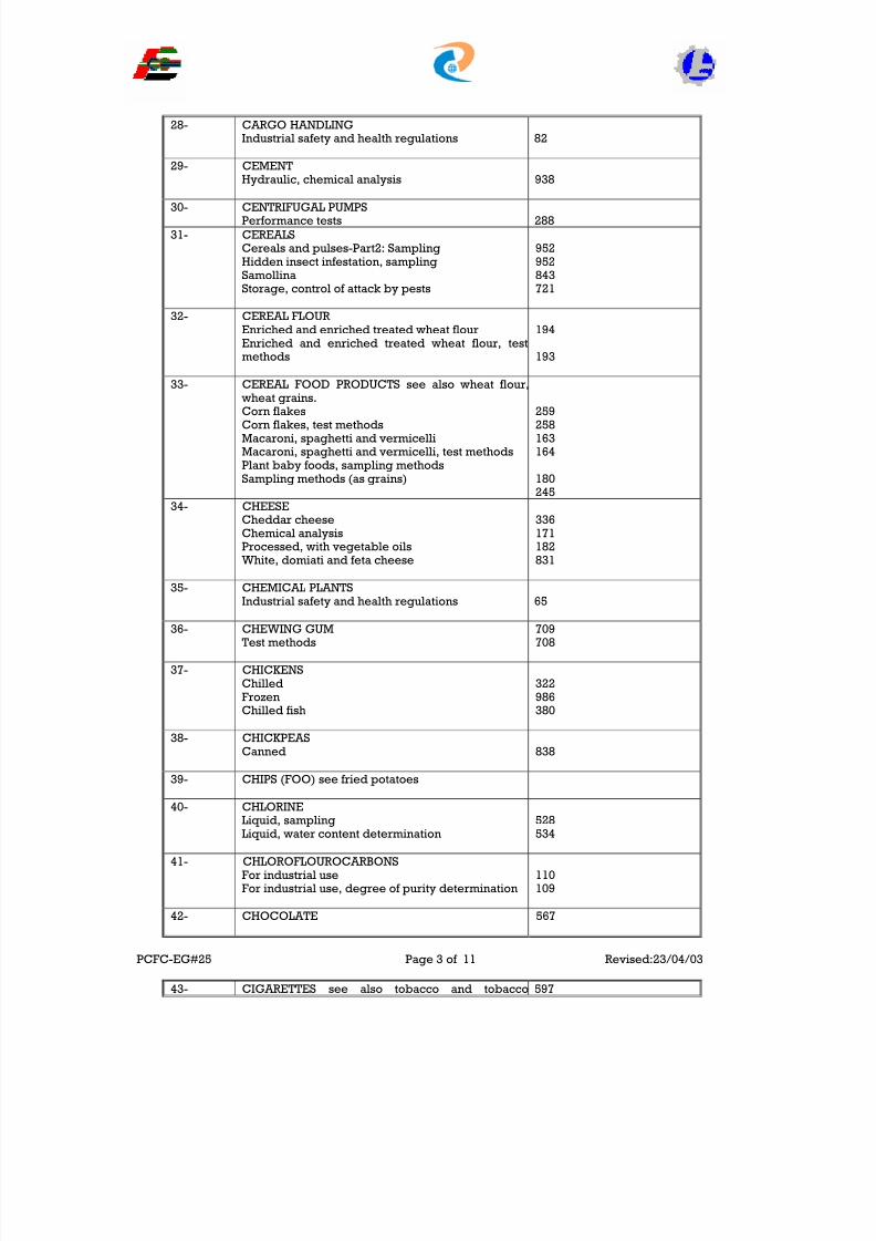
8/8/2019 EHS Env Guidelines
http://slidepdf.com/reader/full/ehs-env-guidelines 86/155
28- CARGO HANDLINGIndustrial safety and health regulations 82
29- CEMENTHydraulic, chemical analysis 938
30- CENTRIFUGAL PUMPSPerformance tests 288
31- CEREALSCereals and pulses-Part2: SamplingHidden insect infestation, samplingSamollinaStorage, control of attack by pests
952952843721
32- CEREAL FLOUREnriched and enriched treated wheat flourEnriched and enriched treated wheat flour, testmethods
194
193
33- CEREAL FOOD PRODUCTS see also wheat flour, wheat grains.Corn flakesCorn flakes, test methodsMacaroni, spaghetti and vermicelliMacaroni, spaghetti and vermicelli, test methodsPlant baby foods, sampling methodsSampling methods (as grains)
259258163164
180245
34- CHEESECheddar cheeseChemical analysisProcessed, with vegetable oilsWhite, domiati and feta cheese
336171182831
35- CHEMICAL PLANTSIndustrial safety and health regulations 65
36- CHEWING GUMTest methods
709708
37- CHICKENSChilledFrozenChilled fish
322986380
38- CHICKPEASCanned 838
39- CHIPS (FOO) see fried potatoes
40- CHLORINELiquid, samplingLiquid, water content determination
528534
41- CHLOROFLOUROCARBONSFor industrial useFor industrial use, degree of purity determination
110109
42- CHOCOLATE 567
PCFC-EG#25 Page 3 of 11 Revised:23/04/03
43- CIGARETTES see also tobacco and tobacco 597

8/8/2019 EHS Env Guidelines
http://slidepdf.com/reader/full/ehs-env-guidelines 87/155
products. Alkaloid determinationCarbon monoxide determinationSamplingSmoking machine-definitions and standardconditions
101292598103
44- COFFEECaffeine content determinationGreen coffee beansGreen Coffee in bags, sampling
Vocabulary
720442410850
44- COLD STORAGEFruits & vegetables, physical condition in coldstoresOrangesPears
434
225321
45- COLORANTS (FOOD)Test methods
2322
46- COMPOST
Municipal solid waste 901
47- COMPOUND FERTILIZERSTest methods 879
48- COMPRESSED GASSafety 61
49- COMPRESSED GAS EQUIPMENTSafety 215
50- COOLANTSSee engine coolants
51- CORNPuffedPuffed, test methods
784784
52- CORNED BEEFCanned 504
53- CORN FLAKESTest methods
259258
54- CRUDE OILStandard test for cloud point 560
55- CUSTARDPowder 853
56- CYLINDERSDissolved acetylene, basic requirements 744
57- DATESPrepackagedWhole, prepacked, test method
656781, 657
PCFC-EG#25 Page 4 of 11 Revised:23/04/03

8/8/2019 EHS Env Guidelines
http://slidepdf.com/reader/full/ehs-env-guidelines 88/155
58- DETERGENTS Anionic – active matterLiquid detergents for dish washing, test methodsSampling divisionSynthetic powdered detergents
391
256151
59- DIAMMONIUM PHOSPHATE
Fertilizer 69460- DICHLORODIFLUOROMETHANE
See chlorofluorocarbons
61- DICHLOROTETRAFLUROMETHANESee chlorofluorocarbons
62- DRAINAGE See sewage and drainage
63- DRIED FOODSConditions of storage 168
64- EDIBLE OILS AND FATSStorage, transport and handling
Vegetable, Blanded Vegetable ghee
1018658991
65- EGGSChemical testingChicken
4451002
66- ENVIRONMENTAL CONTROLIndustrial safety and health regulations 209
67- EXPIRATION PERIODSFood products, part 1Food products, part 2
1501023
68- EXPLOSIVESDusts, explosives and blasting agents, safety andregulationsTransportation of explosive substances
210
975
69- FERTILIZERS Ammonium sulphateDiammonium phosphateCompoundCompound, test methodsMonoammonium phosphateOrganicOrganic, test methodsSingly superphosphateSuperphosphate, test methods
Triple superphosphate
297694803879693555556339878
74570- FIRE EXTINGUISHERS
Dry chemical powder, multipurposePhosphatePortable, dry powderPortable, foam
340637636
PCFC-EG#25 Page 5 of 11 Revised:23/04/03

8/8/2019 EHS Env Guidelines
http://slidepdf.com/reader/full/ehs-env-guidelines 89/155
71- FIRE PROTECTIONBuildings safety 208
72- FISHCanned pacific salmonChilledHandling fresh fish at sea, general specification
Hygienic practice for preparation and storingMicrobiological testsPhysical and chemical testsShrimps, frozenSmoked
524380514
1026
655589582270
73- FLAMMABLE AND COMBUSTIBLE LIQUIDSContainer and portable tank storage, safetyIndustrial and bulk plants, SafetyService stations, processing plants, Refineries andchemical plants, safetyTanks, piping and accessories, safety
63
64
6562
74- FLAVORINGSUse in foodstuffs 707
75- FLAVOURED ARTIFICALPowders 848
76- FRLOURESCENT LAMPSBallast’s for high pressure mercury vapor lampsBallast’s, for high pressure mercury vapor lamps,test methods
368
36977- FOOD ADDITIVES See also sugar (food)
Food preservatives. AntioxidantsColoring matterColoring matter, test methodsEmulsifiers, Stablizers, thicknersIn vegetable oils and fatsIn vegetable oils and fats, test methodsSweeteners, determination of
35723223811917840
78- FOOD FLAVORINGS 70779- FOOD HYGIENE
Fresh meat 81580- FOOD PACKAGING
Packages, General requirementsPlastics cups and containers for packing beverages
838462
81- FOOD PRESERVATIVESBenzoic acid, sodium benzoate and potassiumbenzoateBenzoic acid, sodium benzoate and potassiumbenzoate, test methodsPermitted for use in foodstuffs
Salts of sulphurous acidSalts of sulphurous acid, test
172
173
356
175176
PCFC-EG#25 Page 6 of 11Revised:23/04/03
82- FOOD PRODUCTS See also animal fats, baby foods,bakery products, cereal food products, cocoa,dairy products, eggs, flour, halawa, hard candy,honey, meat and meat products, processed foods,
sugar, tehena vegetable fats and oils, vegetable.

8/8/2019 EHS Env Guidelines
http://slidepdf.com/reader/full/ehs-env-guidelines 90/155
and oils, vegetable.Expiration periods, part1Expiration periods, part 2Omycotoxins, maximum limits permitted aflatoxins
Prepackaged foods, labelingTransportation and storage of chilled and frozenfoods
1501023841
9323
83- FOOD TESTING Antioxidants permitted for use in food productsBaker’s yeast and inactive dried yeastBlack and white pepper, determination of pipelinecontentCereals, determination of falling numberCereals and pulses, determination of mass of 1000grainsFruit and vegetable determination of soluble solidscontentFruit and vegetable determination of sorbic acidFruit and vegetable determination of specificgravity, pectin, pentosansMeat and meat products, glucono-delta-lactone
content determinationMeat and meat products, - I (+) – glutamic acidcontent determinationMeat and meat products – I (-) – hydroxyprolinecontent determination
Vegetable fats and oils, fatty acids determination,part 2
Vegetable products, chloride contentdetermination
Vegetables, canned, microbiological tests Vegetables, caned, physical and chemical tests
795
264819
792791
1004
347
260
108
105
106275
313
178177
84- FOOD TRANSPORATION 81585- FRESH VEGETABLES
OnionsPotatoesSampling methods
Vegetables marrow
103010291251033
86-- FREEZERSHousehold electric freezersHousehold electric freezers, test methods
923924
87-- FRIED POTATOESTest methods
286285
88-- FROZEN FOODSMutton and goat meatPeasShrimpsSpinach
StrawberriesTemperature of frozen foods, determinationTransportation and storage
996345582811
415324
323
PCFC-EG#25 Page 7 of 11Revised:23/04/03
89- FRUIT DRINKSFlavoured artificial powder 848

8/8/2019 EHS Env Guidelines
http://slidepdf.com/reader/full/ehs-env-guidelines 91/155
Fruit drink 79490- Fruits See also tomatoes.
Net weight and drained weight determinationWater insoluble solids contents determinationWater melon
244
239
1035
91- FRUIT NECTARSMango nectarMixed fruit nectars
249846
92- FUELS See automotive fuels, aviation, fuels,gasoline, liquid fuels
93- GAS CONTAINERSPressure regulations, Lpg.Pressure regulations, lpg., test methods
586587
94- GAS CYLINDERS See cylinders, Personnelrequirements for professions 472
95- GASES See hazardous materialsDissolved acetyleneDissolved acetylene, test methodsLiquefied petroleumLiquefied petroleum, test methodsOxygen, medical useOxygen, medical use, test methodsOxygen industrialOxygen industrial, test methods
557559672673563564139138
96- GASOLINE See also automotive fuels, aviationfuels.
97- GLASS BOTTLES98- GLUTEN-FREE FOODS 102199- GOAT MEAT
Fresh, chilled and frozenOrgans and viscera
996835
100- GRAIN (FOOD) See cereal, food Products, wheatgrains
101- GRAPE FRUIT JUICE 490
102- GREEN BEANS103- HAZARDOUS Materials See also industrial safetyand health regulationsBulk plants, safetyGases, hydrogen, safetyGases, LPG, safetyGases, nitrous oxide and oxygen, safetySpray finishing paints
6457605866
104- HEALTH AND SAFETY REGULATIONS Seeindustrial safety and health regulations
105- HONEY 147106- HYDROGEN107- HYGIENE
Food plants and personnelPoultry abattoirs, personnel
21713
108- INDUSTRIAL AND BULK PLANTS
PCFC-EG#25 Page 8 of 11Revised:23/04/03
109- INDUSTRIAL SAFETY AND HEALTH REGULATIONS
Equipment, forging machinesEquipment, machinery, general requirementsEquipment, materials handlingEquipment, machinery, power press
71124
214

8/8/2019 EHS Env Guidelines
http://slidepdf.com/reader/full/ehs-env-guidelines 92/155
Equipment, mills, plastic and rubber industryPetroleum industriesProcessing paintsRefineriesService stationTanks, flammable materials
Vehicle mounted work platformsWelding, cutting and brazing
7275
746565656280220
110- JAMS 640111- JELLIES 193112- KEROSENE113- LABAN AND LABENH 816114- LABELING
Pre-packaged foodsTobacco products
9246
115- LAMPSBallast’s for high pressure mercury vapor lampsHigh pressure mercury vapour lamps
369
829116- LEAD ACID BATTERIES 34117- LIQUEFIED PETROLEUM GAES118- LIVESTOCK TRANSPORTATION
Sheep & goat 714119- LPG See liquefied petroleum gases120- LUBRICATING OILS
Demulsification number determinationDiesel oil
131477
121- MACARONITest methods
163164
122- MAIZE OILEdible 114
123- MALT BEVERAGETest methodos
10271028
124- MANGO JUICE 249
125- MANGOESCannedGuide to storage
951847
126- MARMALADES 640127- MEAT
Ash determinationBeef and buffalo fresh, chilled and frozenStarch content determinationTotal fat contentTotal phosphorus content determination
993838985107
128- MICROBIOLOGICAL TESTINGCheeseDetection of salmonellaDrinking and mineral waterGenera guidancePreparation of samplesSterility testWater non-routine tests
179287818810261590378
PCFC-EG#25 Page 9 of 11Revised:23/04/03
129- MILKDetection of salmonellaDriedLiquid, microbiological testsPhysical and chemical analysisRaw
99410571570174

8/8/2019 EHS Env Guidelines
http://slidepdf.com/reader/full/ehs-env-guidelines 93/155
Sampling methodsSterilized
569985
130- MILK PRODUCTSCream 651
131- MINERAL WATERBottled naturalDetermination of arsenic
Determination of bariumDetermination of borateNon-routine microbiological testsSamplingUnbottled drinking water
987117
154642379111149
132- MONOAMMONIUM PHOSPHATEFertilizer 693
133- MUTTON See also meatFresh, chilled and frozen 997
134- MUSTARD SEED OIL135- MOZZARELLA CHEESE 833136- OCCUPATIONAL SAFETY See industrial safety137- ORGANIC FERTILIZERS 555138- PACKAGING See also this (containers)
Food PackagesPlastic bottles for chemical materials and products
Plastic cups for beveragesPolyethylene films used for packaging non-foodstuffs
839132
462393
139- PERSONAL PROTECTIVE EQUIPMENT Seeindustrial safety and health regulations
140- PETROLEUM INDUSTRY See also refineriesSafety 74
141- POLLUTANT GASESMotor vehicles, diesel engines, exhaust gaseouspollutants determinationMotor vehicles, diesel engines, limits of pollutantsemitted to the atmosphere
414
144
142- Quality assurance inspection and test 9003143- RADIOACTINE MATERIALS145- RAW MILK 174146- REFINERIES147- SAFETY
Fire safety, colors & signs 522148- SEMOLINA 843149- SLAUGHTERING
Animal slaughtering requirements 993150- STERILIZED MILK 985151- STORAGE See also cold storage, expiration
periodsCereals and pulses, control of attack by pestsChilled and frozen foods, general requirements
721323
PCFC-EG#25 Page 10 of 11Revised:23/04/03
152- STORESFor frozen and chilled foodstuff, definitions,classification and terminologyFor frozen and chilled foodstuff, generalrequirementsFor frozen and chilled foodstuff, labelling and
marking
968
969
970
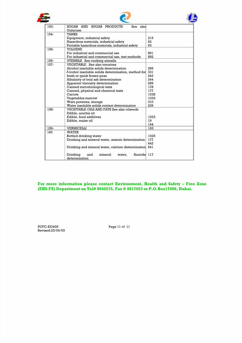
8/8/2019 EHS Env Guidelines
http://slidepdf.com/reader/full/ehs-env-guidelines 94/155
153- SUGAR AND SUGAR PRODUCTS See alsoGulucose
154- TANKSEquipment, industrial safetyHazardous materials, industrial safetyPortable hazardous materials, industrial safety
2156263
155- TOLUENE
For industrial and commercial useFor industrial and commercial use, test methods 891892156- UTENSILS See cooking utensils157- VEGETABLE See also tomatoes
Alcohol insoluble solids determinationlcohol insoluble solids determination, method for
fresh or quick frozen peas Alkalinity of total ash determination Apparent viscosity determinationCanned microbiological testsCanned, physical and chemical testsCarrots
Vegetables marrowWare potatoes, storageWater insoluble solids content determination
29933124324429917817710381033310239
158- VEGETABLE OILS AND FATS See also oilseedsEdible, arachis oilEdible, food additivesEdible, maize oil
102319144
159- VERMICELLI 163160 WATER
Bottled drinking waterDrinking and mineral water, arsenic determination
Drinking and mineral water, calcium determination
Drinking and mineral water, fluoridedetermination
1025177642641
117
For more information please contact Environment, Health and Safety – Free Zone(EHS-FZ) Department on Tel# 8040275, Fax # 8817023 or P.O.Box17000, Dubai.
PCFC-EG#25 Page 11 of 11Revised:23/04/03

8/8/2019 EHS Env Guidelines
http://slidepdf.com/reader/full/ehs-env-guidelines 95/155
ENVIRONMENTAL GUIDELINE No.26
DUCAMZ ENVIRONMENTAL GUIDELINES
1 INTRODUCTION
The Workshop and Maintenance areas of DUCAMZ needs to be upgraded to meet EHS guidelines inline with the standard operating practices of PCFC.
2 GENERAL GUIDELINES
Substitute a less toxic raw material. Switch to non-chlorinated compounds, such as citrus based solvent for parts cleaning. Always ask for and keep MSDS of any product used in the facility. Always use funnels or pumps to dispense chemicals. Keep all chemicals in sealed containers with tight fitting lids. Keep lids on all solvent containers when not in use. Seal all floor drains to prevent ground contamination. Use dirty solvents first when cleaning parts and use a filter on parts washer to extend life of
solvent. Consider switching to water based cleaner instead of chlorinated spray cans of brake/ carburetor
cleaner. Contact a PCFC approved contractor for recycling of used solvent Contact a PCFC approved transporter for disposal of used hazardous wastes. Consider installation of an on-site distillation unit to recycle spent solvents. Dirty floor washings should be routed with other industrial waste water (effluent) to a proper
holding tank for suitable disposals.
3 ANTIFREEZE
When good antifreeze must be removed for repairs only, save it and return it to the system after
repairs have been completed. Separate spent antifreeze from other wastes. Consider keeping antifreeze in two separate, closed containers: one marked waste anti freeze for
those that cannot be reused, and on marked usable antifreeze only for anti freeze that can bereused.
If on-site recycling is not feasible, recycle your antifreeze through an authorized recycling serviceor dispose as per PCFC procedures.
If you recycle antifreeze on the premises, filters and other recycling products may be hazardous. You need to make a waste determination.
Consider purchasing equipment to recycle antifreeze on-site. Check before putting recycledantifreeze into any vehicle.
Don’t mix waste antifreeze with any other waste. Keep it separate. Don’t mix propylene glycol & ethylene glycol – it’s harder to recycle. Don’t ever dispose of antifreeze in a storm drain, septic tank, or dry well. Don’t ever pour antifreeze on the ground/sewer system.
4 BRAKE FLUID
Collect brake fluid in a separate, marked, closed container and identify a contractor that willrecycle it. Disposals shall be done as per PCFC procedures
Don’t put brake fluid into your used oil container. Don’t pour brake fluid down any drain or on the ground. Don’t spray brake cleaner around brake fluid.
PCFC-EG#26 Page 1 of 5Revised:23/04/03

8/8/2019 EHS Env Guidelines
http://slidepdf.com/reader/full/ehs-env-guidelines 96/155
5 CARBURETOR CLEANER (COLD TANK)
Consider eliminating chlorinated carburetor cleaner and switching to a less hazardous, non – chlorinated cleaner.
Keep the carburetor cleaner container closed when not in use to avoid evaporation. When carburetor cleaner is spent, contact a company to recycle it or properly dispose of it at a
permitted hazardous waste disposal facility. Don’t pour carburetor cleaner down any storm drain, or into a septic system, dry well, or sewer.
Don’t put sludge from your cold tank into the skip or on the ground.
6 FLOOR CLEANING WASH WATER
Keep your floors as clean as possible at all times. Catch leaks before they spill on floor anddispose the residue in the appropriate waste container.
Clean small, non-chlorinated spills immediately with absorbent material and save for reuse untilabsorbing ability is gone. It can then be placed in a waste container for suitable disposal. It isrecommended to connect all industrial wastewater sources to a holding tank.
Use absorbent pads to collect floor cleaning wash water and wring out the pads into appropriate waste container when saturated.
Do not dispose into sewerage system. Use holding tanks.
Receive permission from PCFC for disposal. Don’t dispose of absorbents contaminated with chlorinated solvents in a skip. These arehazardous.
Don’t allow floor cleaning wastewater to flow into a storm drain (inside or outside) or seweragesystem.
7 FREON (CFC’s)
Freon (if imported) should be registered with the Federal Environmental Agency (FEA). Keep records of the dates and quantities of freon recovered and recycled. Don’t evaporate or vent freon to the atmosphere.
8 HOT TANK SOLUTION
Consider alternative cleaning methods such as detergent-based cleaning liquids. Accumulate all sludge from hot tanks in a closed, marked, plastic container. Determine through testing if sludge is hazardous, and dispose accordingly. Don’t dispose of spent hot tank solution down any drain or on ground. Don’t dispose of hot tank sludge in a skip or on the ground.
9 LEAD ACID BATTERIES
Properly dispose of batteries by delivering them to: a wholesaler or retailer from whom you purchased the batteries, a permitted secondary lead smelter,
a facility that recycles the batteries by extracting the lead, or a collection center that sends batteries to a smelter or recycler. Dispose/recycle batteries at least every six months with approvals form PCFC Store batteries upright in a secure, leak resistant, covered location. Check regularly for leaks, if leaking dispose as hazardous waste. Don’t store batteries outside. Don’t dispose batteries in the garbage or skip. Don’t take lead acid batteries to a unsecure landfill. Don’t burn/incinerate batteries. Don’t pour acid down the drains.
PCFC-EG#26 Page 2 of 5 Revised:23/04/03

8/8/2019 EHS Env Guidelines
http://slidepdf.com/reader/full/ehs-env-guidelines 97/155
10 PAINT WASTE
Use paints with no heavy metals as far as possible. Use water based paints wherever feasible. Re-use thinner until capability is exhausted. Spray paint systems should be controlled to mitigate overspray. Use proper paint booths
approved by PCFC. Keep lids tight on all cans of solvent or paint. Vent paint emissions only through suitable extraction/filtration systems Dispose paint residues, filters, wastewater through PCFC as per approved procedures. Don’t dispose any waste paint to ground, sewer etc. Don’t evaporate paint waste. Don’t buy/store more paint than required.
11 PRESSURIZED SPRAY CANS
Consider phasing out spray cans in your shop and switch to non-aerosol. Consider using refillable canisters that use compressed air, portable parts washers or pump
sprayers. Make sure spray cans are empty prior to disposal. If a spray can malfunctions, handle as hazardous waste, don’t dispose as general waste. Recycle empty metal cans.
12 SHOP TOWELS
Minimize use of shop towels by preventing spills/leaks. Use cloth towels that can be cleaned/reused. When possible, use less hazardous cleaning solvents. Keep soiled shop towels in a closed container marked separately for disposal or cleaning. Minimize disposable paper towels or rags. Don’t dispose dirty towels in your skip. Don’t saturate the towels, if you do, wring them out and reuse the liquid. Don’t dispose solvents by pouring the into containers of used shop towels.
13 SOLVENTS & SOLVENT TANKS
Consider using less hazardous solvents. Install a filter on the solvent sink and dispose filters as hazardous waste. Make sure a solvent is dirty before using a new solvent. Remember that sludges, filters etc. are hazardous and should be handled, disposed as such. Keep different types of solvents in separate, clearly labelled, closed containers. Don’t dispose spent solvents by pouring them on the ground/floor drains or by evaporating. Don’t mix solvents with other wastes or used oil.
14 SPRAY CABINET WASH WATER
Skim off oil from wash water and store separately for disposal. Contact PCFC authorities for disposal of washwater. Accumulate paint sludge in closed containers for disposal as per standard procedures. Close of all drains that lead to storm sewers, septic tanks etc. Check with PCFC authorities for disposal of any wastes from this unit. Don’t dispose paint sludge or any hazardous waste in the domestic skip.
PCFC-EG#26 Page 3 of 5Revised:23/04/03
15 SUMP SLUDGES

8/8/2019 EHS Env Guidelines
http://slidepdf.com/reader/full/ehs-env-guidelines 98/155
Have sludge segregated/tested/analyzed prior to disposal. Keep all records of disposal. Don’t put hazardous sludge in the skip or ground. Don’t use a domestic tanker service for sludge disposal. Obtain relevant forms from PCFC for disposal to DM facilities.
16 TRANSMISSION FILTERS
Remove oil by draining for minimum 24 hours. Keep filters in a container marked separately for “Transmission Filters”. Try & locate a waste recycling facility for these filters. Put transmission fluid drained from filters in your “Used Oil” Container. Don’t discard any filters in the trash skip.
17 TRANSMISSION FLUID
Catch the Automatic Transmission fluid (ATF) in containers when removed/drained form the vehicle.
Designate a proper area in the workshop to help consolidate/arrange wastes. Keep used oil in a properly marked container (Used Oil Only). Use a specially designated Mop and bucket (or sponge) to collect spills and transfer to a used
ATF container. Make sure that your container for wastes is placed in a secure area and train your workers. Don’t dispose used ATF in a sewer, septic tank, drainage system. Don’t mix brake or carburetor cleaners/fluids with ATF. Dispose ATF in accordance with PCFC procedures. Use only approved transporters to collect/dispose the wastes.
18 USED OIL
Catch oil dripping from parts, transfer funnels, leaking vehicles etc. in a drip pan. Keep used oil in a properly marked container (Used Oil Only). Make sure that your container for wastes is placed in a secure area and train your workers. Use only approved transporters to collect/dispose the wastes. Know where the waste oil goes from your facility. Keep all disposal /recycling records. Don’t pour used oil on the ground, storm drains, floor drains, septic tank etc. Don’t mix incompatible wastes like brake fluid, used antifreeze, solvent cleaners etc. with used
oils. Try and identify used oil recycling companies instead of disposal.
19 USED OIL FILTERS
Remove oil by puncturing filter and collect after draining for minimum 24 hours. Keep used drained/undrained filters in separate marked containers Keep used oil from filters in a properly marked container (Used Oil Only). Use only approved transporters to collect/dispose the wastes. Dispose filters in accordance with PCFC procedures.
Don’t put filters in your waste skip.
20 UNDERGROUND STORAGE TANKS
Get your underground storage tanks approved by the authority (PCFC).Ensure that the tanks are in compliance with leak detection requirements of PCFCDon’t remove/dispose contents of the storage tanks without PCFC approvals.
PCFC-EG#26 Page 4 of 5 Revised:23/04/03

8/8/2019 EHS Env Guidelines
http://slidepdf.com/reader/full/ehs-env-guidelines 99/155
21 TYRES
Disposal of waste tyres should be as per standard PCFC procedures. Identify retreading companies to recycle the tyres. Store the tires in accordance with PCFC requirements. Don’t accumulate large number of tyres. It is a fire hazard. Don’t illegally dispose, burn tyres.
For more information please contact Environment, Health and Safety – Free Zone(EHS-FZ) Department on Tel# 8040275, Fax # 8817023 or P.O.Box17000, Dubai.
PCFC-EG#26 Page 5 of 5Revised:23/04/03

8/8/2019 EHS Env Guidelines
http://slidepdf.com/reader/full/ehs-env-guidelines 100/155
ENVIRONMENTAL GUIDELINE No.27
GUIDELINES ON CLEANLINESS
1. OBJECTIVES
These guidelines specify the requirements on cleanliness in PCFC to ensure that the work places aremaintained in a manner that will enhance clean environment.
2. SCOPE AND RESPONSIBILITES ( i.e from cradle – to grave)
(i) The Industries
This document follows the chain by which waste is generated and disposed off in a suitable mannerto keep work place in the PCFC free of objectionable waste.
(ii) Roles of PCFC, Industry and Consumers
PCFC being an authority will encourage the implementation of these guidelines to keep theenvironment clean and eventually protect the public from hazards that can affect their health.
The Industry’s Responsibility is to provide a system by which waste is handled and disposed off in amanner that will achieve goal of environment mutation.
The consumers should follow relevant instructions and apply appropriate food hygiene measure.
3. ENVIRONMENTAL HYGIENE
No person is allowed to throw, put, leave, melt or discharge any of the following materials or objectson roads/streets, lanes, alleys, pavements, open spaces, buildings, roofs, walls, stairways and any
other place whether public or private:
a. All kinds of garbage and waste such as refuse, sweepings, rubbish, discarded paper, stagnant water, bathing, laundry, sewerage, absorption pits, cesspools and others.
b. Anything whether a chattel, animal, material or object which may obstruct traffic or pedestriansor occupy the public road or disfigure the public view or beauty in PCFC, or violates therequirements of public hygiene and environment protection and non-pollution.
Exceptions to these precedent provisions are the areas and places, which are specified by PCFC inaccordance with necessary situations, conditions, specifications and permits.
All pedestrians, car drivers and passengers are prohibited from discarding paper or any type of garbage including cigarette butts and spitting in the public road or open spaces whether fenced orunfenced. The car driver shall be jointly liable with the passenger if the passenger commits the said
violation.
Dumping trees and park’s residues in the road and squares whether public or private, and in theopen areas whether fenced or unfenced is prohibited. The responsible parties to the sites specifiedfor that purpose must transport it.
Spitting, Urinating or defecating in places other than those specified for that purpose are prohibited.
PCFC-EG#27 Page 1 of 4Revised:23/04/03
8/8/2019 EHS Env Guidelines
http://slidepdf.com/reader/full/ehs-env-guidelines 101/155
Litter bins allotted by the PCFC for pedestrian’s litter in public places shall not be used for purposesother than its intended purpose. Dumping of domestic waste from camps and stores or combustibleand inflammable materials is also prohibited.
Owners of restaurants, cafeterias, barbeque stalls and other places using open fire or charcoal areprohibited to dump fire residues and flaming coal ashes in litterbins, bags or boxes or in the publicroads. They are also prohibited to place chairs and tables outside their business premises withoutthe PCFC approval.
Empty bottles of carbonated waters and other drinks shall be kept in their respective boxes. Emptyor filled boxes or bottles broken or otherwise shall not be left on the pavements, streets, lanes,squares or public parks.
Tire repairs and oil changing waste should not be left on pavements or roads. These should betransported at their own expense to the designated Municipality places or advise Public HealthServices of EHS-DPA Dept. at 8816128.
Cars, vehicles and other means of transport should not be washed in public roads or open spacesexcept where permitted by the Authority.
Housekeeping both within and outside the industries/showrooms, service stations, canteens andother establishments shall be maintained as per PCFC requirements.
All wastes should be handled and collected in suitable containers for necessary disposal with the approval of theAuthority. No industrial/trade wastes shall be dumped in sewers, garbage bins, roadsides, storm water drains etc.
No wastes (solid, liquid or airborne) shall be disposed/released without appropriate approvals from the Authority.
Looking is not allowed at any of the showrooms, service stations, workshops etc. other than the licensed canteensand eating establishments. These eating establishments shall conform to the requirements of PCFC.
Adequate Fire protection/detection facilities should be provided at all facilities/establishments and this equipmentshould be tested and certified each year from an approved third party agency.
No washing of cars or maintenance activities shall be permitted at any establishment other than the licensed servicestations or car wash centres.
All authorized car wash/maintenance/service stations shall provide suitable collection/treatment/ recycling facilitiesfor the wastewater generated from the same.
All facilities/establishments shall ensure that garbage/domestic wastes are disposed by an approved agency.
Manual Cleaning of vehicles in DUCAMZ showroom plots should not lead to any drainage of contaminated water into adjacent plots/roads/storm water drains etc. and suitable provisions should be made to mitigate sucheventualities. Water Spray washing of vehicles within the showrooms establishment premises is not permitted.
For all spray painting/blasting operations, a proper painting/blasting booth should be constructed with a proper extraction/filtration system. These systems shall be designed to achieve the EHS standards for emissions as per PCFZC/DM guidelines.
All facilities generating wash/process wastewater should have valid disposal permits from PCFC and/or DM.
Wherever applicable, on-site process waste/wash water storage facility for a minimum of 7 days of generationshould be installed to cater for emergencies.
No storage of hazardous chemicals or industrial waste effluent generation shall be allowed inshowroom units.
PCFC-EG#27 Page 2 of 4Revised:23/04/03
Accommodation is not permitted within any of the industrial premises in PCFC -JAFZ/DUCAMZ.

8/8/2019 EHS Env Guidelines
http://slidepdf.com/reader/full/ehs-env-guidelines 102/155
Waste oils shall be recycled/disposed only after requisite approvals from the Authority.
Vehicles shall not be parked on the roads and within roundabouts and only within the company’s premises, allowinga clear 5.5m setback distance for emergency access.
Contact a PCFC approved contractor for recycling of used solvent
Dirty floor washings should be routed with other industrial waste water (effluent) to a proper holding tank for suitable disposals.
Don’t mix waste antifreeze with any other waste. Keep it separate.
Don’t mix propylene glycol & ethylene glycol – it’s harder to recycle.
Don’t ever dispose of antifreeze in a storm drain, septic tank, or dry well.
Don’t ever pour antifreeze on the ground/sewer system.Collect brake fluid in a separate, marked, closed container and identify a contractor that will recycle it. Disposals shall be done as per PCFC procedures.
Don’t pour carburetor cleaner down any storm drain, or into a septic system, dry well, or sewer.
Keep your floors as clean as possible at all times. Catch leaks before they spill on floor and dispose the residue inthe appropriate waste container.
Keep records of the dates and quantities of freon recovered and recycled.
Don’t dispose of hot tank sludge in a skip or on the ground.
Don’t dispose batteries in the garbage or skip.
Use water based paints wherever feasible.
Recycle empty metal cans.
Keep soiled shop towels in a closed container marked separately for disposal or cleaning.
Keep different types of solvents in separate, clearly labeled, closed containers.
Accumulate paint sludge in closed containers for disposal as per standard procedures.
Have sludge segregated/tested analysed prior to disposal. Keep all records of disposal.
Keep filters in a container marked separately for “Transmission Filters.”
Keep used oil in a properly marked container (Used Oil Only).
Keep used oil in a properly marked container (Used Oil Only).
Dispose filters in accordance with PCFC procedures.
Ensure that the tanks are in compliance with leak detection requirements of PCFC.
Identify retreading companies to recycle the tyres.
PCFC-EG#27 Page 3 of 4Revised:23/04/03

8/8/2019 EHS Env Guidelines
http://slidepdf.com/reader/full/ehs-env-guidelines 103/155
All over-ground bulk fuel/chemical tanks should be bunded/dyked by a suitable concrete enclosure to prevent spillsand contamination in case of tank failure/emergencies.
A proper spillage collection facility to be provided for all chemical/fuel storage and mixing/filling/processing areas.
A.C./chiller drains to be discharged into a properly designed soakpit or to the nearest floor drain.
A septic tank and linear soakaway system should be adopted for all areas that do not have a sewerage system.
No cooking is allowed in the company/showroom premises.
Any abrasive blasting shall follow PCFC/DM guidelines for Abrasive blasting.
All facilities generating wash/process wastewater should have valid disposal permits from PCFC and/or DM.
Wherever applicable, on-site process waste/wash water storage facility for a minimum of 4 days of generation to be built to cater for emergencies.
Proper extraction/filtration systems to be provided for the airborne emissions from any proposed machinery.
The drain from compressors/pump rooms/blow down etc. are considered as industrial waste and should beconnected to a proper holding tank of suitable capacity for testing/further assessment.
mm mesh to be provided for all the washbasins in any restaurants. Also, a proper Wade Actimatic grease trap should be installed for the drainage from the cutting/cooking areas in the restaurants.
No storage of hazardous chemicals or industrial waste effluent generation shall be allowed in pre-built units.
Chimneys as well as ducting from any extraction/filtration systems shall be released at a minimum of 3 m. above theroof ridge of the tallest adjacent building.
A proper facility should be provided for placing/servicing of a domestic solid waste skip on the site.
The trucks/vehicles loaded with material, which might be blown by wind, are prohibited from being on the roadswithout tarpaulin cover. Also the leakage/spill of any loaded sand or any materials is prohibited from vehicles/truckson being on road in PCFC/JAFZ/DUCAMZ.
For more information please contact Environment, Health and Safety – Free Zone(EHS-FZ) Department on Tel# 8040275, Fax # 8817023 or P.O.Box17000, Dubai.
PCFC-EG#27 Page 4 of 4Revised:23/04/03
8/8/2019 EHS Env Guidelines
http://slidepdf.com/reader/full/ehs-env-guidelines 104/155
ENVIRONMENTAL GUIDELINE No.28
GENERAL ENVIRONMENTAL GUIDELINES FORMANUFACTURING/ASSEMBLY/SERVICE INDUSTRIES
1 INTRODUCTION
PCFC applies specific environmental guidelines for specific projects on a case-by-case basis. Withrespect to subject types of industries the general environmental guidelines outlined here can be used,but, depending on the project, the requirements may need to be supplemented by additionalrequirements.
Projects must comply with PCFC polices and guidelines, which emphasize pollution prevention Reuse,Recovery, Recycle (RRR) options, waste minimization, including the use of cleaner productiontechnologies. The intent of the guidelines is to minimize resource consumption, including energy use,and to eliminate or reduce pollutants at the source. For ease of monitoring, maximum permittedemissions limits are often expressed in concentration terms- for example, milligrams per liter (mg/I)for liquid effluents and, for air emissions, milligrams per normal cubic meter (mg/Nm3), where“normal” is measured at one atmosphere and 0 Celsius. The focus, however, should continue to be onreducing the mass of pollutants emitted to the environment. Dilution of effluents and air emissions to
achieve maximum permitted values is unacceptable. Occasionally, emissions limits are specified inmass of pollutants per unit of production or other process parameter. In such cases, the limits includeleaks and fugitive emissions.
Pollution control systems may be required in order to meet specified emissions limits. These systemsmust be will maintained and operated and must not be fitted with overflow or bypass devices unlesssuch devices are required for emergencies or for safety purposes.
The following sections contain requirements for air emissions, liquid effluents, hazardous wastes, andsolid wastes. Sections on ambient noise and monitoring requirements are included. The final sectionsummarizes the key steps that will contribute to minimizing the impact of the project on theenvironment.
2 EMISSIONS GUIDELINES
Emission levels for the design and operation of each project is established through the EnvironmentalImpact Assessment (EIA) process.
The guidelines given below present emissions levels acceptable to PCFC. All of the maximum levelsshould be achieved at all the time that the plant or unit is operating.
A Air Emissions
Most of the air emissions from subject types of industrial facilities originate with the fuel used forheating purposes or for generating steam for process purposes. Particular emissions that mayoriginate in the process are addressed case by case. Concentration of contaminants emitted from thestacks of significant sources including boilers, furnaces, etc., should not exceed the limits presentedin Attachment-1.
The plant owner is required to demonstrate full compliance with the emissions limits specified in Attachment –1. The following methods may be used to demonstrate compliance.
For point sources compliance with the guidelines for particulate matter may be demonstrated bymaintaining the stack emissions opacity below 20%. Opacity can be determined visually by aqualified observer, with a continuous opacity meter, or with a mobile light detection and ranging(LIDAR) system.
PCFC-EG#28 Page 1 of 10Revised:23/04/03

8/8/2019 EHS Env Guidelines
http://slidepdf.com/reader/full/ehs-env-guidelines 105/155
The sulfur content of fuels may be used to demonstrate compliance with the sulfur dioxide (SO2)emissions guidelines. The guidelines are met by the use of liquid fuels with sulfur content of 1% orless. The client must maintain records of fuel analyses to demonstrate that the sulfur content of thefuel is at or below the specified levels.
Manufacturers performance guarantees can be used to demonstrate that the emissions guidelines fornitrogen oxides (NOx) are met. The performance guarantees must be verified by conducting aninitial performance test after the equipment has been commissioned. The sponsor must maintainrecord to demonstrate that the equipment is operated within manufacturers specifications.
Alternatively, stack emissions can be monitored for specified contaminants. The monitoring must besufficiently frequent to demonstrate continued compliance with the guidelines.
To ensure that ambient air conditions are not compromised, concentration of contaminants measuredimmediately outside the project property boundary should not exceed the limits shown in
Attachment-2.
B Liquid Effluents
Process wastewater, domestic sewage and contaminated storm water and runoff must meet themaximum limits shown in Attachment-3. Pollutants of concern that are not included in Attachment–3
will be specified by the PCFC separately.
Liquid effluent may be discharged to central waste water treatment system, Dubai Municipality (DM)or Harbour. The company is to confirm that the waste treatment system has the capacity and ismanaged adequately to treat the project’s liquid effluents. Such proper treatment is required prior todischarge to the harbor based on which PCFC approves harbour disposal.
C Hazardous Materials And Wastes
Free Zone companies shall, whenever possible, use non-hazardous instead of hazardous materials. All hazardous wastes, process residues, solvents, oils, and sludge’s must be properly disposed of toDM.
The following management measures for handling hazardous wastes and materials should beimplemented:
i All hazardous (ignitable, reactive, flammable, radioactive, corrosive and toxic) materials must bestored in clearly labeled containers or vessels.
ii Storage and handling of hazardous materials must be in accordance with local regulation orinternational standards and appropriate to their hazard characteristics. Storage and liquidimpoundment areas for fuels, raw and in process materials solvents, wastes and finished productsshould be designed with secondary containment (e.g.,dikes and berms) to prevent spills and thecontamination of soil, groundwater, etc.
iii Fire prevention systems and secondary containment should be provided for storage facilities, where necessary or required by regulations, to prevent fires or the release of hazardous materialsto the environment.
iv Formulations containing chromates should not be used in water treatment processes.
v Transformers or equipment containing polychlorinated biphenyls (PCBs)or PCB-contaminated oilshould not be installed. Existing equipment containing PCBs or PCB-contaminated oil should bephased out and disposed of in a manner consistent with the relevant requirements.
PCFC-EG#28 Page 2 of 10Revised:23/04/03

8/8/2019 EHS Env Guidelines
http://slidepdf.com/reader/full/ehs-env-guidelines 106/155
vi Several chemicals classified as ozone- depleting substances (ODSs) are scheduled forphase out under Montreal Protocol on Substances That Deplete the Ozone Layer.They include chloro-flurocarbons (CFCs); halons;1,1,1-trichloroehtane(methylchloroform);carbontetrachloride;hydrochlorofluorocarbons(HCFCs);hydrobromofluorocarbons(HBFCs); andethyl bromide .These chemicals are currently used in a variety of applications, includingdomestic, commercial, and process refrigeration (CFCs and HCFCs); domestic, commercial, andmotor vehicle air conditioning ( CFCs and HCFCs);manufacturing of foam products(CFCs);solvent cleaning applications (CFCs, HCFs, methyl chloroform, and carbon tetrachloride);aerosol propellants (CFCs) fire protection systems (halons and HBFCs); and crop fumigants(methyl bromide). No systems or processes are to be installed using CFCs, halons, 1,1,1-trichloroehtane, carbontetrachloride, mehtlylbromide, or HBFCs. HCFCs should be consideredonly as interim or bridging alternatives, since they too are to be phased out.
D Solid Wastes
Free Zone Companies are to implement the following practices for managing solid wastes generatedin the course of operating the facility:
• Recycle or reclaim materials where possible.• If recycling or reclamation is not practical, wastes must be disposed of in an environmentally
acceptable manner and in compliance with DM/PCFC regulations.
Other Environmental Requirements:
3. AMBIENT NOISE
Noise abatement measures should comply with maximum allowable noise level of 70 dBA at thefence line of plant.
4. MONITORING AND REPORTING
Free Zone Companies are required to maintain record of air emissions, effluents, and hazardous wastes sent off site, as well as significant environmental events such as spills etc that may have animpact on the environment. The information should be reviewed and evaluated to improve theeffectiveness of the environmental protection plan.
A Air EnvironmentThis section establishes reporting, testing, monitoring and analyses requirements for sources of airpollution located or proposing to locate in FZ. The purpose of these requirements is to enable the
Authority to assess compliance with the ambient air quality criteria and air emission limitationsspecified in Attachment –1.
Prior to commencing construction or modification, all sources of air pollution not specificallyexempted must prepare and submit an EIA report and include a section pertaining to the airenvironment. Depending on the nature and size of the source, Authority may require the applicant toprepare an ambient air quality analysis and/or provide ambient air monitoring data. After start-up,large emission sources and potentially hazardous or nuisance-type sources are required to conduct
source emission (performance testing) and report the results to Authority for compliance evaluation.For certain specified emission sources, continuous air emission monitoring and quarterly reporting isrequired on a case to case basis.
At any time, after start-up, Authority may request any industrial facility to prepare an updated airemissions inventory or provide other information relating to the source in question.
PCFC-EG#28 Page 3 of 10Revised:23/04/03
B Air Emissions Performance Testing

8/8/2019 EHS Env Guidelines
http://slidepdf.com/reader/full/ehs-env-guidelines 107/155
i Performance tests are required on a case-by-case basis, for any source that may be hazardous tothe environment or may be an odour nuisance. The aim of performance testing is to verify apollutant’s emission concentrations or rate at a point source and to ensure that there is no violationof the industrial source emission criteria stated in Attachment – 1 and/or ambient air quality (atfenceline) criteria as stated in Attachment –2 or any emission limit used for compliance evaluation.It should be noted that as a general industry requirement stack testing ports and work platformsshould be installed at all facilities, which have a potential to release pollutant quantities or are
otherwise subject to the criteria stated above.
ii Performance tests shall be done at earliest after normal operation. These tests shall be conductedby an independent consultant. The date, time and place of any performance test shall be given to
Authority at least one week in advance so they may witness such tests.
iii Performance tests shall consist of the determination of exhaust gas temperatures and volumetricflow rates and gas analyses for the pollutants and efficiency of abatement equipment for which thetest is required. The tests shall be conducted according to the accepted international referencetest methods.
iv Each performance test shall consist of a minimum of three separate sampling runs conducted within a 48-hour period. Each run shall be obtained while the source is operating at normal load.The arithmetic mean of the results of the three runs shall be used for the purpose of determiningcompliance with applicable emission limitations.
v The results of the performance tests shall be submitted to Authority within one month of theircompletion. If Authority finds that procedures and/or methodologies used for any tests wereinappropriate or defective, it may require a retest.
C Water Environment
This section establishes reporting, testing, monitoring and analyses requirements for sources of water pollution located or proposing to locate at the FZ. The purpose of these requirements is toenable Authority to assess compliance with harbour wastewater discharge criteria specified in
Attachment – 3.
At least six (6) months prior to commencing construction of any industrial or other wastewater-producing facility, or adding to or modifying an existing facility, an Environmental Impact
Assessment (EIA) report, containing a water environment details as per Authority EIA Guidelinesshall be submitted by the industry or facility to Authority. After start-up, the facility owner/operatormay be required to sample/analyze effluents initially and/or periodically to demonstratecompliance with the discharge criteria specified earlier. For groundwater appropriate number of boreholes will be installed for quarterly monitoring and reporting. For some effluent parameters, acontinuous monitoring and monthly quality-reporting is required on a case-by-case basis.
D Wastewater Discharge Performance Testing
Performance tests are required for any facility that discharges wastewater to the FZ harbour, or Gulf (open sea). Performance tests shall be done within one-month time after normal operation. Thedate, time and place of any performance test shall be given to Authority at least one week inadvance.
E RRR Options, Cleaner Production and Waste Minimization:
Free Zone companies should adopt reuse, recovery or recycling (RRR) options for wastewatergenerated. It is emphasized to minimize the generation of wastewater and adopt cleaner productionpractices.
PCFC-EG#28 Page 4 of 10Revised:23/04/03

8/8/2019 EHS Env Guidelines
http://slidepdf.com/reader/full/ehs-env-guidelines 108/155
F Noise Environment & Performance Testing
In line with Authority’s requirements for premises a noise performance testing, at the boundary fenceline, would be conducted within one month upon normal operation. On a case-by-case basis orannual noise level testing and reporting is required.
G Solid/Hazardous Waste:
All solid/hazardous waste generated in PCFC entities is to be disposed off as per PCFC/DMguidelines. RRR Options (see above Section) and wastes minimization must be adopted by all FreeZone companies
5. KEY ISSUES FOR ENVIRONMENT CONTROL
The key production and control practices that will assist in meeting emissions requirements can besummarized as follows:
• Where feasible, choose RRR options, cleaner production, integrated pollution control, waste minimization, energy-efficient and environmentally sound processes.• Ensure that control, treatment, and monitoring facilities are properly maintained and that
they are operated according to their instruction manuals.
PCFC-EG#28 Page 5 of 10Revised:23/04/03

8/8/2019 EHS Env Guidelines
http://slidepdf.com/reader/full/ehs-env-guidelines 109/155
Attachment –1
SOURCE EMISSION CRITERIA
GENERAL: STATIONARY SOURCES
AIR POLLUTANTS EMISSION LIMITS FOR STATIONARY SOURCES
SUBSTANCE SYMBOL SOURCES EMISSION LIMITS(mg/Nm 3)
Visible Emissions Combustion sourcesOther sources
250none
Carbon Monoxide CO All sources 500Nitrogen Oxides(Expressed as nitrogen dioxide) NOx
Combustion sources
Material producingindustries
Other sources
Gas fuel-350Liquid fuel-5001500
200Sulphur Dioxide SO 2 Combustion sources
Material producingindustriesOther sources
5002000
1000Sulphur TrioxideIncluding Sulphuric Acid Mist(Expressed as sulphur trioxide)
SO 3 Material producingindustriesOther sources
150
50Total Suspended Particles
TSPCombustion sourcesCement IndustriesOther sources
25050150
mmonia and AmmoniumCompounds (expressed asammonia)
NH3 Material producingindustriesOther sources
50
10Benzene C 6H6 All sources 5
Iron Fe Iron & Steel foundries 100Lead and its compounds(expressed as lead)
Pb All sources 5
ntimony and its Compounds(Expressed as antimony)
Sb Material producingindustriesOther sources
5
1rsenic and its Compounds
(expressed as arsenic) As All sources 1
Cadmium and its compounds(expressed as cadmium)
Cd All sources 1
Mercury and its compounds(expressed as mercury)
Hg All sources 0.5
Nickel and its compounds(expressed as nickel)
Ni All sources 1
Copper and its compounds(expressed as copper)
Cu All sources 5
Hydrogen Sulphide H 2S All sources 5Chloride Cl Chlorine Works
Other sources20010
Hydrogen Chloride HCI Chlorine WorksOther sources
20020
Hydrogen Fluoride HF All sources 2Silicon Fluoride SiF 4 All sources 10
PCFC-EG#28 Page 6 of 10Revised:23/04/03

8/8/2019 EHS Env Guidelines
http://slidepdf.com/reader/full/ehs-env-guidelines 110/155
Fluoride and its CompoundsIncluding HF & SiF 4 (expressed fluoride)
F- Aluminum smeltersOther sources
2050
Formaldehyde CH 20 Material producingindustriesOther sources
20
2Carbon C Anode production
Waste incineration25050
Total Volatile OrganicCompounds(expressed as total organiccarbon -TOC)
VOC All sources 20
Dioxins and Furans All sources 1 ng TEQ/m 3
Notes:
1. The concentration of any substance specified in the first column emitted from any source specified inthe third column shall not at any point before admixture with air, smoke or other gases, exceed thelimits specified in the fourth column.
2. “mg” means milligram;3. “ng” means nanogram.4. “Nm 3” means normal cubic meter, being that amount of gas which when dry, occupies a cubic meter
at a temperature of 25 degree Centigrade and at an absolute pressure of 760 millimeters of mercury(1 atm) ;
5. The limit of “Visible Emission” does not apply to emission of water vapour and a reasonable periodfor cold start up, shutdown or emergency operation.
6. The measurement for “Total Suspended Particles (TSP)’’ emitted from combustion sources should be@12% reference CO 2.
7. The total concentration of the heavy metals (Pb, Cd, Ni, Hg, Cu, As & Sb) must not exceed 5 mg/Nm 3.
8. VOC limit is for unburned hydrocarbons (uncontrolled).9. The emission limits for all the substances exclude “Dioxins and Furans” are conducted as a daily
average value.10. TEQ means “Total Equivalent Quantity.” Dioxins and Furans” Average values shall be measured
over a sample period of a minimum of 6 hours and a maximum of 8 hours. The emission limit valuerefers to the total concentration of dioxins and furans calculated using the concept of toxicequivalence.
11. For source standards air pollutants emission limits from incinerators refer to relevant Annexes.
PCFC-EG#28 Page 7 of 10 Revised:23/04/03

8/8/2019 EHS Env Guidelines
http://slidepdf.com/reader/full/ehs-env-guidelines 111/155
Attachment –2
AMBIENT AIR QUALITY STANDARDS
(AIR POLLUTANTS LIMITS IN THE AMBIENT AIR)
SUBSTANCE SYMBOL MAX.ALLOWABLE LIMITS(ug/m 3)
AVERAGE TIME
Sulphur DioxideSO 2 350
150
60
1 hour
24 hours
1 year
Carbon MonoxideCO 30 mg/m 3
10 mg/m3
1 hour
8 hour
Nitrogen DioxideNO 2 400
150
1 hour
24 hours
OzoneO 3 200
120
1 hour
8 hour
Total Suspended ParticlesTSP 230
90
24 hour
1yearParticulate Matter (with 10microns or less indiameter )
PM 10 150 24 hours
Lead Pb 1 1 year
PCFC-EG#28 Page 8 of 10Revised:23/04/03

8/8/2019 EHS Env Guidelines
http://slidepdf.com/reader/full/ehs-env-guidelines 112/155
Attachment –3
STANDARDS FOR DISCHARGE OF WASTE WATER TO HARBOUR (1)
MAX. ALLOWABLEPARAMETERS (es2) SYMBOL UNIT STANDARD (7)
Physical PropertiesColour - Colour units 50Total Suspended Solids TSS mg/1 50Floating Particles - mg/m 3 NonepH - pH units 6-9 (6) Temperature (3) T C 35 (max)Total Dissolved Solids TDS mg/1 1500Turbidity - NTU 75Inorganic Chemical Properties
Ammonia Total as (N) NH4+
mg/1 2Biochemical Oxygen Demand BOD 5 mg/1 50
Chemical Oxygen Demand COD 100Chlorine Residual (4) Total Cl - mg/1 1.0Cyanide CN mg/1 0.05
Dissolved Oxygen (5) DO mg/1 >3
Fluoride F- mg/1 20Nitrate NO 3-N mg/1 40Sulfide S -2 mg/1 0.1Total Kjeldahl Nitrogen as (N) TKN mg/1 10Total Phosphorus, as (P) PO 4
-3 mg/1 2Trace Metals
Aluminum Al mg/1 20
Antimony Sb mg/1 0.1 Arsenic As mg/1 0.05Barium Ba mg/1 2Beryllium Be mg/1 0.05Cadmium Cd mg/1 0.05Chromium, total Cr mg/1 0.2Chromium, VI Cr +6 mg/1 0.15Cobalt Co mg/1 0.2Copper Cu mg/1 0.5Cyanide CN mg/1 0.1Fluoride F mg/1 25Iron Fe mg/1 2
Lead Pb mg/1 0.1Manganese Mn mg/1 0.2Mercury Hg mg/1 0.001Nickel Ni mg/1 0.1Selenium Se mg/1 0.02Silver Ag mg/1 0.005Zinc Zn mg/1 0.5
PCFC-EG#28 Page 9 of 10Revised:23/04/03
Organic Chemical Properties
Halogenated Hydrocarbons mg/1 Nil

8/8/2019 EHS Env Guidelines
http://slidepdf.com/reader/full/ehs-env-guidelines 113/155
and PesticidesHydrocarbons HC mg/1 15Oil & Grease O & G mg/1 10Phenols - mg/1 0.1Solvent - mg/1 noneTotal Organic Carbon TOC mg/1 75
Biological PropertiesColon Group TC No./100 cm 2 5000Egg Parasites - - NoneFecal Coliform Bacteria - Cells/100 ml 1000Total Coliform - MPN/100ml 1000Warm Parasites - None
Notes:
1) Any discharge to surface drainage ditches must be authorized by PCFC and shall only be permitted inexceptional circumstances.2) For any parameters not identified, specific standards will be determined on a case-by-case basis.3) Temperature limit is the maximum allowed for discharge.
4) Chlorine residual is after 30 minutes contact and is total residual chlorine5) Dissolved oxygen requirement is a minimum concentration requirement7) Inclusive range not to be exceeded.7) With respect to Harbor Discharge Standard, FZ Cos. should concentrate on full compliance of harbourdischarge Standard Any sample repeated twice excedance of allowable standard will permit imposition of appropriate sanction as per FZ rules.
For more information please contact Environment, Health and Safety – Free Zone(EHS-FZ) Department on Tel# 8040275, Fax # 8817023 or P.O.Box17000, Dubai.
PCFC-EG#28 Page 10 of 10Revised:23/04/03

8/8/2019 EHS Env Guidelines
http://slidepdf.com/reader/full/ehs-env-guidelines 114/155
ENVIRONMENTAL GUIDELINE No.29
EHS PERFORMANCE AUDITS
1. OVERVIEW
Recent years have seen tremendous growth in public awareness and concern for the environmentand its impact on the quality of life. The proposed auditing is a commonly used term that describes anexamination of operating facility’s operation and practices. Such audit would serve as a managementtool comprising a systematic, documented, periodic and objective evaluation of how well a particularactivity is performing with regard to PCFC EHS aims/requirements.
All FZ companies should be encouraged first to get EMS ISO 14001 and OHSAS 18001, as relevant,certifications. Because current environmental legislation, marketing requirements and communityexpectations reflect an increased awareness of the need to protect the environment that requires allaspects of the industrial activities to be undertaken in an environmentally responsible way.Environmental audits can help the industry to become environmentally responsible and demonstratethis responsibility to the community.
Environmental audits help in assuring the accuracy and relevance of environmental monitoring. Theyalso measure an organization’s environmental performance and can encourage continual
improvement. Procedures for conducting an environmental audit vary from simple checklists (see Attachment) to complex standards or programs. These procedures use a systematic approach torecord whether and operation is meeting its environmental objectives.
The steps include: pre-audit planning site activities (interviews and inspections); gathering andevolution of audit evidence; development of audit findings; and recommendations, documentationand reporting of the findings and audit follow-up (action plan, etc).
In their most basic application, environmental audits help companies demonstrate to regulatoryauthorities that they are complying with EHS legislation and regulations and the conditions containedin pollution control approval, discharge licenses/permits and leases. Identifying issues through theaudit process may also lead to more efficient operations that go well beyond regulatoryrequirements.
2 PERFORMANCE AUDIT REQUIREMENT
This type of audit begins with an overview of operating facility, determining the mass emissions tothe air, water, etc. and comparing with the permitted levels.
For today’s industry, regulations, financial reporting equipments, market competition and communityexpectations require environmental performance to be assessed and reported.
The need to carry out an environmental audit will vary depending upon the type of organization andthe objectives of the audit. The principal aims of an environmental audit are to identify and evaluatepotential liabilities, risks and hazards. This in turn will assist in assessing the viability of operationsafter including the cost of reducing environmental risks and liability to acceptable levels.
There is no single environmental audit procedure applicable to all situations. An audit can takedifferent forms to achieve different objectives. The reason for undertaking and audit and the agreedoutcomes are the deciding factors.
For auditing purpose, the FZ industries can be graded as follows:
(i) Grade – A:
FZ Cos. having major chemical/manufacturing processes with serious potential for EHS impacts.
PCFC-EG#29 Page 1 of 4Revised:23/04/03
(ii) Grade-B:

8/8/2019 EHS Env Guidelines
http://slidepdf.com/reader/full/ehs-env-guidelines 115/155
FZ Cos. having medium chemical/manufacturing activities (like blending unit, chemical filling, etc) with medium potential for EHS impacts.
(iii) Grade-C:
FZ Cos. having no chemical/manufacturing activities (like trading/offices, etc) with no potential forEHS impacts.
The companies where EMS ISO 14001 is implemented would be required to set relevant performanceobjectives and targets for the management system which link back to the commitments as per policyi.e. prevention of pollution, continual improvement and compliance of performance.
Thus, EMS coupled with OHSAS i.e. EHS Performance Auditing can be used as a framework to help FZindustries improve their overall performance.
3 EHS Performance Reporting:
A salient requirement to the FZ companies as part of compliance evaluation/EHS Performance Audit
would be to regularly submit their EHS monitoring reports to PCFC. This would cover all EHSaspects, releases to the environment, discharges and /or emissions as part of approval/permits, etc.
4 Benefits of EHS Performance Audits:
The proposed audit would focus on all type of wastes. In the past, waste management hasconcentrated on end-of–pipe waste treatment; designing waste treatment plants and installingpollution control equipment to prevent contamination of the environment.
A different philosophy has emerged in recent times, that of waste prevention and reduction. Now weask how can we prevent the generation of this waste? How can we reduce this waste? Can we reuseor recover or recycle (RRR options) this waste?
This progressive shift from inspections to proposed audits would have the following benefits:• Waste quantities are reduced;• Raw material consumption and therefore costs are reduced;• Waste treatment costs are reduced;• The pollution potential is reduced;• Working conditions are improved;• Process efficiency is improved.
In order to prevent or reduce waste generation we need to examine the process to identify theorigins of waste, the operational problems associated with the process and those areas whereimprovements can be made.
An audit is the first step to achieve maximum resource optimization and improved processperformance. It is common sense approach to problem identification and problem solving. A wasteaudit enables you to take a comprehensive look at a site or process to facilitate your understandingof material flows and to focus your attention on areas where waste reduction and therefore costsaving is possible.
Undertaking a waste audit involves observing, measuring recording data and collecting andanalyzing waste samples. To be effective it must be done thoroughly together with full managementand industry support.
PCFC-EG#29 Page 2 of 4Revised:23/04/03

8/8/2019 EHS Env Guidelines
http://slidepdf.com/reader/full/ehs-env-guidelines 116/155
A good waste audit:• Defines sources, quantities and type of waste being generated;• Collates information on unit operation, raw materials, products, water usage and wastes;• Highlights process inefficiencies and areas of poor management;• Helps set targets for waste reduction;• Permits the development of cost-effective waste management strategies;• Raises awareness in the workforce regarding the benefits of waste reduction;• Increases you knowledge of the processes;• Helps to improve process efficiency.
t the plant level, wastes can be traced to particular processes allowing allocationof treatment changes where necessary; and at the process level the exact originsof wastes can be identified enabling waste reduction measures to be established.
5 Conclusions/Recommendations:
(i) The proposed swift from current Inspections to Audits is feasible. The most–relevant type of audit would be EHS Performance Audit, as we would be assessing the overall performance of ongoingactivities.
(ii)
Environmental auditing has become an essential management tool for any industrial operation. It isnot an end in itself, but the basis on which an environmental action plan can be developed toimprove environmental performance.
(iii) It is recommended that EHS Performance Audits should be part of an ongoing EHS management andimprovement program, that is, not a one-off event but a periodic reassessment of the environmentalmanagement system.
(iv) Performance auditing is and emerging and evolving technique. It has been common in industry onlysince the 1980’s.
(v) International standards for auditing environmental management systems should be used as a usefulbasis for developing the techniques. Audit remains the most effective tool for assessing occupational,health, safety and environmental risks and for measuring such potential impacts of and operatingfacility.
(vi) The proposed audit outcome recommendations would range from minor changes in operatingprocedures and training, to performing a detailed waste inventory to determine the source of problems within the Free Zone companies.
PCFC-EG#29 Page 3 of 4Revised:23/04/03

8/8/2019 EHS Env Guidelines
http://slidepdf.com/reader/full/ehs-env-guidelines 117/155
EHS Performance Audit checklist
A Applicable Standards Yes No A1
A2 A3
A4
A5
Have all the necessary licenses/permits etc. relating to EHSrequirements been obtained?
Are the licenses/permits for EHS standards being complied with?If and EIA/RA studies were conducted for the project at the design stage,are the relevant commitments/predictions, relating to emission levels,mode of operation etc. being complied with?Have any problem areas discussed in A2 and A3 been highlighted andrectified?Have the deficiencies in EIA /RA and design methodologies beenofficially recorded and fed back to the appropriate consultants who willbe involved in future EIA/RA and design work?
B Design IssuesB1
B2B3
B4
Have the initial objectives been met? (e.g. plant efficiency, air emissions,noise control, etc.)
If not, have the reasons for such failings been identified?Has consideration been given to whether the designs selected wereappropriate in the light of B2?Have the deficiencies in the design methodology been officiallyrecorded and fed back to the appropriate consultants who will beinvolved in future design work?
C Waste IssuesC1
C2
C3
C4
C5
Does the pollution control/abatement technology employed removepollutants at the guaranteed efficiencies?Do the monitoring techniques employed detect down to the guaranteedlevels?Has any ambient air monitoring been performed? If so, do the resultscompare with any predictions made in an EIA if previously conducted?Have any other deficiencies/potential improvements in the design asregards attaining the desired environmental standards beenhighlighted?Have the deficiencies /potential improvements form B4 been officiallyrecorded for future reference?
D Health & Safety IssuesD1 Have all Health and Safety Issue been addressed as per RA Study?
For more information please contact Environment, Health and Safety – Free Zone(EHS-FZ) Department on Tel# 8040275, Fax # 8817023 or P.O.Box17000, Dubai.
PCFC-EG#29 Page 4 of 4Revised:23/04/03

8/8/2019 EHS Env Guidelines
http://slidepdf.com/reader/full/ehs-env-guidelines 118/155
ENVIRONMENTAL GUIDELINE No.30
GUIDELINES FOR CONDUCTING WASTE AUDIT IN PCFC
1 BACKGROUND
A waste Audit as a procedure for surveying processes and/or equipment and identifying waste minimizationoptions as a necessary first step to waste minimization. The results of a Waste Audit can provide managementwith timely and useful information for developing a viable waste Management plan that can accomplish thefollowing goals:
• Save money by reducing water treatment and disposal costs, raw material purchases, and other operatingcosts.
• Reduce potential environment liabilities.• Protect public health and worker health and safety.• Protect the environment.• Improve corporate image.
The purpose of a general waste audit is to identify all possible outputs from an industrial process to eachsegment of the environment and to assess the likely impact of those wastes as well as compliance to localstandards and regulations.
Waste Audit will be required for certain operating industries (as decided by EHS-FZ Dept –JAFZA) to ensurecompliance with the provisions of PCFC Environmental Rules and Requirements 3 rd Edition (2003).
2 GUIDELINES FOR WASTE AUDIT REPORTS:
A Objectives of Waste Audit
The objectives for conducting a waste audit are to:
• Identify each and every gas, liquid and solid waste stream generated by the industry.• Quantify and characterize every waste stream.• Establish how and why the waste stream is generated.• Calculate the costs incurred with pretreatment, storage, handling and disposal.• Determine the liabilities associated due to the generation of those wastes, including compliance with EHS-FZ
Dept/PCFC Regulations.• Identify options for effective waste management so that a waste management plan can be developed including
waste minimization potential.
B Stages of Waste Audit
• Selections of an Audit team.• Determination of Audit Scope.• Collection of preliminary Data.• Identification and characterization of input materials, products and waste streams.• Comprehensive plant and environmental analysis.• Evaluation of data and regulatory compliance.• Preparation of Waste Audit Report.
i Selection of an Audit TeamAn audit team usually comprises a leader and several members. However its exact size will be determined bythe time span of the audit, manpower availability and plant size.
PCFC-EG#30 Page 1 of 5Revised:23/04/03

8/8/2019 EHS Env Guidelines
http://slidepdf.com/reader/full/ehs-env-guidelines 119/155
The audit team may consist of:
• Consultants (to be priorily approved by EHS-FZ Dept. of PCFC)• Site or Works/Production Manager/• Environmental Engineer/Office.• Supervisor with hands-on Knowledge of the process.• Process Engineer.• Waste treatment supervisor, etc etc.
ii Determination of Audit Scope
This will usually be determined by EHS-FZ Dept. of PCFC at the time of requiring the Audit. The approvedconsultant would propose Audit Scope for PCFC approval. An audit may involve a single industrial process or an entire industrial facility.
An audit may be limited to the outputs from the plant of facility or may involve detailed assessment of wasteimpacts on the environment.
iii Collection of Preliminary Data
The objective of this activity is to collect all necessary background information on the plan’s operation. Thetypes of information that can be useful in conducting the audit are as follows:
a. Design Information Process flow diagrams Materials and heat balances of the processes. Operating manuals and process descriptions. Equipment lists. Equipment specifications. Plan, elevation and layout of plant. Other.
b. Raw material and production information
Product composition and batch sheets. Raw materials (including water. Fuel)analysis. Operating procedures. Operating schedules. Material Safety Data Sheets(MSDS). Other.
c. Environmental Information Waste disposal receipts (eg. Dubai Municipality-DM) and data. Emission inventories. Waste analysis reports(eg. air emissions, wastewater, etc). Correspondence with PCFC/EHS-FZ Dept. (i.e EHS Issues). EHS permits. Risk Assessment (RA) and Environmental Impact Assessment (EIA).
Other. (eg. Cleaner Production Alternatives, Odor Complaints from neighbors, etc).
d. Economic Information Waste treatment and disposal costs. Product and raw materials costs. Water consumption costs. Energy consumption costs. Operating (eg. Fuel, Raw Materials) and maintenance costs. Other.
PCFC-EG#30 Page 2 of 5Revised:23/04/03

8/8/2019 EHS Env Guidelines
http://slidepdf.com/reader/full/ehs-env-guidelines 120/155
iv Identification and Characterization of Input materials, product and waste streams
a. Identify and name each and every waste stream (gas, liquid and solid), input material stream and output product stream using the flow diagrams of the facility.
b. Collect data on input material and product streams: Hazardous components.
Material handling and storage Production rate. Products.
c. Collect data on the identified waste streams. Nature of waste (gas, liquid, solid). Generation rate. Composition of the waste. Quantity (present and future). Degree of hazard (toxicity, flammability, etc.). Current disposal practices for each stream.
v Material Balance
A material balance is an important tool to identify losses and to verify quantitative data of material input andoutput of the production process.
The principle of mass conservation is as shown in the diagram below:
Total Mass in = Total Mass Out + Mass Accumulated
A material balance should be made individually for all components that enter and leave the process. Whenchemical reactions take place in a system there is and advantage of doing “elemental balances” for chemicalelements in a system. Material balance can assist in determine concentrations of waste constituents whereanalytical teat data is limited.
vi Comprehensive plant AnalysisA comprehensive plant assessment is performed to fill gaps identified during the review of the backgroundinformation. This is mainly achieved through a sit inspection. The main objective of an inspection is to achievea fuller understanding of the principal and secondary causes of waste generation and to cover the items missedin the preliminary data collection stage.
PCFC-EG#30 Page 3 of 5Revised:23/04/03
vii Evaluation of Data and Regulatory Compliance.
MassTotal mass in
Air Emissions
Mass out
ProductMass out
Mass out
. Solid Waste . Wastewater

8/8/2019 EHS Env Guidelines
http://slidepdf.com/reader/full/ehs-env-guidelines 121/155
a. Waste Impacts. Evaluate the volumes and components contained in each waste stream against the regulatory standards. Report on company environmental practices, policies and monitoring systems. Assess the impact of waste streams on the surrounding environment.
b. Minimizationa. Generate waste minimization options for each waste stream such as: Changing plant operation and/or procedures by improved house keeping and educating employee about
waste reduction. Substituting non-toxic material in the production process. Reclaiming materials to avoid creating wastes. Adopting Reuse, Recovery and Recycling (RRR) alternatives Modifying equipment to improve efficiency. Altering final product to eliminate processes that recate waste. Using clean fuel.
b. Conduct preliminary technical and economic assessment of waste minimization options by consideringthe following factors:
Technical factors:
Product quality. Safety/occupational health. Production constraints/flexibility. Space requirements. Installation time, production downtime. Reliability. Commercial availability. Proven performance in a similar application. Regulatory constraints. Expertise/skill level required for operation and maintenance.
Economic factors: Capital cost. Operating cost.
Potential savings. Profitability requirement using methods like payback period, net present value (discounted cash flow)and return on investment.
Intangible or qualitative benefits such as improvement in corporate image and, reduction of risk andliability associated with the avoidance of penalties for non-compliance and cost of workerscompensation.
viii Preparation of Waste Audit ReportWhen all the information and findings are collected, they should be dated, documented and filed for futurereference. The final product of a waste audit is a report that presents the results of the audit andrecommendations of waste minimization options. A suggested format for the Waste Audit Report outline isgiven below:
a.
Introduction Give a brief description of company’s operations, dates when audit was conducted, and team members
involved. Mention environmental and/or other related EHS issues (i.e air emissions, wastewater, hazardous, H &
S issues, etc) that provide the basis for the audit.
PCFC-EG #30 Page 4 of 5Revised:23/04/03
b. Scope of Audit

8/8/2019 EHS Env Guidelines
http://slidepdf.com/reader/full/ehs-env-guidelines 122/155
Give a brief description of target processes and equipment that are selected including the rationale for the selection.
Provide a site plan showing the drainage system, wastes discharge point and interim storage onsite, air,wastes) facility layout and surrounding land uses/neighbors, etc.
c. Results of Audit
Provide both qualitative and quantitative description of waste steams(eg. air, wastes) identified. Describe problems in process operation and maintenance, waste management methods and practices,
storage and handling of raw materials (including water, fuel) and spill control.
d. Evaluation of Audit Provide technical and economic assessment of identified waste minimization options. Assess compliance with EHS-FZ Dept/PCFC regulations. Evaluate impact of the plant on the local environment with respect to air emissions, solid/liquid
wastes. Recommend changes to management policies or practices including cleaner production and RRR
options as alternatives.
There are many informative websites related to the audits. Please visit www.epa.gov/Environmental , www.policyworks.gov ,www.ea.gov.au websites
For more information please contact Environment, Health and Safety – Free Zone(EHS-FZ) Department on Tel# 8040275, Fax # 8817023 or P.O.Box17000, Dubai.
PCFC-EG#30 Page 5 of 5Revised:23/04/03

8/8/2019 EHS Env Guidelines
http://slidepdf.com/reader/full/ehs-env-guidelines 123/155
ENVIRONMENTAL GUIDELINE No.31
ENVIRONMENTAL GUIDELINES FOR DUBAI METALS ANDCOMMODITIES CENTRE (DMCC)
1. INTRODUCTION
DMCC would apply specific environmental guidelines for its projects on a case-by-case basis. With respect toDMCC types of industries the general environmental guidelines outlined here can be used, but, depending on the
project, the requirements may need to be supplemented by additional requirements.
DMCC clients are required to comply with its relevant, polices and guidelines, which emphasize pollution prevention, Reuse, Recovery, Recycle (RRR) options, waste minimization, including the use of cleaner productiontechnologies. The intent of the guidelines is to minimize resource consumption, including energy use, and toeliminate or reduce pollutants at the source. For ease of monitoring, maximum permitted emissions limits are oftenexpressed in concentration terms- for example, milligrams per liter (mg/I) for liquid effluents and, for air emissions,milligrams per normal cubic meter (mg/Nm3), where “normal” is measured at one atmosphere and 0 Celsius. Thefocus, however, should continue to be on reducing the mass of pollutants emitted to the environment. Dilution of effluents and air emissions to achieve maximum permitted values is unacceptable. Occasionally, emissions limits arespecified in mass of pollutants per unit of production or other process parameter. In such cases, the limits includeleaks and fugitive emissions.
Pollution control systems may be required in order to meet specified emissions limits. These systems must be wellmaintained and operated and must not be fitted with overflow or bypass devices unless such devices are required for emergencies or for safety purposes.
The following sections contain requirements for air emissions, liquid effluents, hazardous wastes, and solid wastes.Sections on ambient noise and monitoring requirements are also included. The final section summarizes the keysteps that will contribute to minimizing the impact of the project on the environment.
2. EMISSIONS GUIDELINES
Emission levels for the design and operation of each project is established through the Environmental ImpactAssessment (EIA) process.
The guidelines given below present acceptable emissions levels. All of the maximum levels should be achieved at allthe time that the plant or unit is operating.
A. Air Emissions
Most of the air emissions from subject types of industrial facilities originate with the fuel used for heating purposesor for generating steam for process purposes. Particular emissions that may originate in the process are addressedcase by case. Concentration of contaminants emitted from the stacks of significant sources including boilers,furnaces, etc., should not exceed the limits presented in Attachment-1.
The plant owner is required to demonstrate full compliance with the emissions limits specified in Attachment –1.The following methods may be used to demonstrate compliance.
For point sources compliance with the guidelines for particulate matter may be demonstrated by maintaining thestack emissions opacity below 20% or 250 mg/m 3 of Particulate Matter. Opacity can be determined visually by aqualified observer, with a continuous opacity meter, or with a mobile light detection and ranging (LIDAR) system.
PCFC-EG#31 Page 1 of 13 Revised:23/04/03

8/8/2019 EHS Env Guidelines
http://slidepdf.com/reader/full/ehs-env-guidelines 124/155
The sulfur content of fuels may be used to demonstrate compliance with the sulfur dioxide (SO2) emissionsguidelines. The guidelines are met by the use of liquid fuels with sulfur content of 1% or less. The client mustmaintain records of fuel analyses to demonstrate that the sulfur content of the fuel is at or below the specified levels.
Manufacturers performance guarantees can be used to demonstrate that the emissions guidelines for sulfur dioxide(SO 2) and nitrogen oxides (NOx) are met. The performance guarantees must be verified by conducting an initial
performance test after the equipment has been commissioned.
The sponsor must maintain record to demonstrate that the equipment is operated within manufacturersspecifications.
Alternatively, stack emissions can be monitored for specified contaminants. The monitoring must be sufficientlyfrequent to demonstrate continued compliance with the guidelines.
To ensure that ambient air conditions are not compromised, concentration of contaminants measured immediatelyoutside the project property boundary should not exceed the limits shown in Attachment-2.
B. Liquid Effluents
Proper treatment facilities for process wastewater and domestic sewage should be provided or the same to bedisposed to Dubai Municipality (DM) facility. Please refer to Attachment-3 for DM Standards applicable to pre-treated wastewater disposal at their central wastewater treatment plant and re-use in irrigation.
C. Hazardous Materials And Wastes
DMCC clients shall, whenever possible, use non-hazardous instead of hazardous materials. All hazardous wastes, process residues, solvents, oils, and sludge’s must be properly disposed of to DM.
The following management measures for handling hazardous wastes and materials should be implemented:
i. All hazardous (ignitable, reactive, flammable, radioactive, corrosive and toxic) materials must be stored inclearly labeled containers or vessels.
ii. Storage and handling of hazardous materials must be in accordance with local regulation or internationalstandards and appropriate to their hazard characteristics. Storage and liquid impoundment areas for fuels, rawand in process materials solvents, wastes and finished products should be designed with secondarycontainment (e.g.,dikes and berms) to prevent spills and the contamination of soil, groundwater, etc.
iii. Fire prevention systems and secondary containment should be provided for storage facilities, where necessaryor required by regulations, to prevent fires or the release of hazardous materials to the environment.
iv. Formulations containing chromates should not be used in water treatment processes.
v. Transformers or equipment containing polychlorinated biphenyls (PCBs) or PCB-contaminated oil should not be installed. Existing equipment containing PCBs or PCB-contaminated oil should be phased out and disposedof in a manner consistent with the relevant requirements.
PCFC-EG#31 Page 2 of 13Revised:23/04/03

8/8/2019 EHS Env Guidelines
http://slidepdf.com/reader/full/ehs-env-guidelines 125/155
vi. Several chemicals classified as ozone- depleting substances (ODSs) are scheduled for phase out under MontrealProtocol on Substances That Deplete the Ozone Layer. They include chloro-flurocarbons (CFCs);halons;1,1,1-trichloroehtane (methylchloroform) ;carbontetrachloride;hydrochlorofluoro,carbonsHCFCs);hydrobromofluorocarbons (HBFCs);and methyl bromide .These chemicals are currently used in avariety of applications, including domestic, commercial, and process refrigeration (CFCs and HCFCs);
domestic, commercial, and motor vehicle air conditioning ( CFCs and HCFCs);manufacturing of foam products (CFCs);solvent cleaning applications (CFCs, HCFs, methyl chloroform, and carbon tetrachloride);aerosol propellants (CFCs) fire protection systems (halons and HBFCs); and crop fumigants (methyl
bromide). No systems or processes are to be installed using CFCs, halons, 1,1,1-trichloroehtane,carbontetrachloride, mehtlylbromide, or HBFCs. HCFCs should be considered only as interim or bridgingalternatives, since they too are to be phased out.
3 SOLID WASTE
DMCC companies are to implement the following practices for managing solid wastes generated in the course of operating the facility:
• Recycle or reclaim materials where possible.• If recycling or reclamation is not practical, wastes must be disposed of in an environmentally acceptable
manner and in compliance with DM regulations.
4 OTHER ENVIRONMENTAL REQUIREMENTS:
A Ambient Noise
Noise abatement measures should comply with maximum allowable noise level of 70 dB at the fence line of plant.
B Monitoring and Reporting
DMCC companies are required to maintain record of air emissions, effluents, and hazardous wastes sent off site, aswell as significant environmental events such as spills etc that may have an impact on the environment. Theinformation should be reviewed and evaluated to improve the effectiveness of the environmental protection plan.
C Air EnvironmentThis section establishes reporting, testing, monitoring and analyses requirements for sources of air pollution locatedor proposing to locate in DMCC. The purpose of these requirements is to assess compliance with the ambient air quality criteria and air emission limitations specified in Attachment –1.
Prior to commencing construction or modification, all sources of air pollution not specifically exempted must prepare and submit an EIA report and include a section pertaining to the air environment. Depending on the natureand size of the source, Authority may require the applicant to prepare an ambient air quality analysis and/or provideambient air monitoring data. After start-up, large emission sources and potentially hazardous or nuisance-type
sources are required to conduct source emission (performance testing) and report the results to Authority for compliance evaluation. For certain specified emission sources, continuous air emission monitoring and quarterlyreporting is required on a case by case basis.
At any time, after start-up, request can be made for any industrial facility to prepare an updated air emissionsinventory or provide other information relating to the source in question.
PCFC-EG#31 Page 3 of 13 Revised:23/04/03
i Air Emissions Performance Testing

8/8/2019 EHS Env Guidelines
http://slidepdf.com/reader/full/ehs-env-guidelines 126/155
a. Performance tests are required on a case-by-case basis, for any source that may be hazardous to the environmentor may be an odor nuisance. The aim of performance testing is to verify a pollutant’s emission concentrations or rate at a point source and to ensure that there is no violation of the industrial source emission criteria stated inAttachment – 1 and/or ambient air quality (at fence-line) criteria as stated in Attachment –2 or any emission limitused for compliance evaluation. It should be noted that as a general industry requirement stack testing ports andwork platforms should be installed at all facilities, which have a potential to release pollutant quantities or areotherwise subject to the criteria stated above.
b. Performance tests shall be done at earliest after normal operation. These tests shall be conducted by anindependent consultant. The date, time and place of any performance test shall be given to Authority at least oneweek in advance so they may witness such tests.
c. Performance tests shall consist of the determination of exhaust gas temperatures and volumetric flow rates andgas analyses for the pollutants and efficiency of abatement equipment for which the test is required. The testsshall be conducted according to the accepted international reference test methods.
d. Each performance test shall consist of a minimum of three separate sampling runs conducted within a 48- hour period. Each run shall be obtained while the source is operating at normal load. The arithmetic mean of theresults of the three runs shall be used for the purpose of determining compliance with applicable emissionlimitations.
e. The results of the performance tests shall be submitted within one month of their completion. If proceduresand/or methodologies used for any tests were inappropriate or defective, a retest may be required.
D Water Environment
This section establishes reporting, testing, monitoring and analyses requirements for sources of water pollutionlocated or proposing to locate at DMCC. The purpose of these requirements is to assess compliance with the DMwastewater discharge criteria.
At least six (6) months prior to commencing construction of any industrial or other wastewater-producing facility, or adding to or modifying an existing facility, an Environmental Impact Assessment (EIA) report, containing a water environment details as per Authority EIA Guidelines shall be submitted by the industry or facility to Authority.After start-up, the facility owner/operator may be required to sample/analyze effluents initially and/or periodically to
demonstrate compliance with the discharge criteria specified earlier. For groundwater appropriate number of boreholes will be installed for quarterly monitoring and reporting. For some effluent parameters, a continuousmonitoring and monthly quality-reporting is required on a case-by-case basis.
E RRR Options, Cleaner Production and Waste Minimization
All DMCC companies should adopt reuse, recovery or recycling (RRR) options for wastewater generated. It isemphasized to minimize the generation of wastewater and adopt cleaner production practices.
F Noise Environment Performance Testing
In line with DMCC requirements (see Attachment-4) for premises a noise performance testing, at the boundaryfence line, would be conducted within one month upon normal operation. On a case-by-case basis or annual noiselevel testing and reporting is required.
G Solid/Hazardous Waste
All solid/hazardous waste generated in DMCC companies is to be disposed off as per DM guidelines. RRR options(see above Section 4.2.1) and wastes minimization must be adopted by all DMCC companies
PCFC-EG#31 Page 4 of 13Revised:23/04/03
5. Key Issues for Environment Control

8/8/2019 EHS Env Guidelines
http://slidepdf.com/reader/full/ehs-env-guidelines 127/155
The key production and control practices that will assist in meeting emissions requirements can be summarized asfollows:
i Where feasible, choose RRR options, cleaner production, integrated pollution control, waste minimization,energy-efficient and environmentally sound processes.
ii Ensure that control, treatment, and monitoring facilities are properly maintained and that they are operatedaccording to their instruction manuals.
6. Case Study: Specific Environmental requirements for Gold/Diamond Refineries and Workshops.
A. EIA STUDY
Gold and Diamond finishing is often a pollution intensive industry, with significant emissions of both metals andorganic process chemicals. It is a major contributor of toxic inputs to water treatment plant, landfill and atmosphere.Due to potential serious environmental impacts a proper EIA study should be required .
B. POLLUTION PATHWAYS
Gold finishing is the application of physical, chemical or electrochemical processes to a work piece to alter itssurface properties or appearance. Chemical (degreasing, cleaning, pickling, etching, coating and electrochemical
(electro-plating, polishing, cleaning and anodizing) processes are the main waste producers. Both types of processeson a work piece are usually performed in baths with chemicals and other compounds, followed by rinsing operations.Process chemicals and compounds which are carried from baths to the water (drag-out) and accumulate in the rinse.
i Rinsing operation waste and drag out pollution.
Gold rinsing generates wastewater, which constitutes the metal finishing industry’s chief overall source of waste.Drag-out in rinse wastewater is responsible for the majority of process chemicals lost in metal finishing and cancontain toxic compounds such as cyanides. Other potential hazards in wastewater can include: nitric, sulfuric,hydrochloric and hydrofluoric acids, cyanides and oil and grease.
Failure to incorporate efficient drainage techniques and equipment while rinsing adds up to 70% more drag outwaste than is otherwise necessary. Operations lacking the technological means to reuse rinse water and to
recover metals and metals salts from rinse water and spent process baths can also contribute to extra water useand toxic effluent. Open – loop systems discharge more waste than do closed loop designs. Excess water consumption and drag out generation increase the volume of wastewater requiring treatment. This produces greatamounts of sludge, a solid waste which can contain toxic metals. To conserve rinse water, reduce drag-out, reuserinse water, and recover metals.
ii Bath solution replacement
The replacement of spent or contaminated baths (plating, cleaning, etc.) can yield much waste which typically istaken off line and treated or put in containers for off-site disposal. This waste contains many of the same toxiccompounds found in rinse water, acids, metals, and cyanides. Facilities without methods to extend bath lifeaugment the quantities of such compounds discharged into the waste stream.
iii Toxic air emissions:
Many gold finishing operations generate air emissions, including mists, from plating baths and vapors fromcleaning and degreasing processes, which use solvents. These toxic emissions can threaten the safe of theworkplace and labors and surrounding area. Operations, which neither provides equipment to prevent the escapeof air pollutants nor substitute less hazardous alternatives where feasible, enhance the danger to workers, their neighbors, and the environment.
PCFC-EG#31 Page 5 of 13 Revised:23/04/03
iv Hazardous process compounds
8/8/2019 EHS Env Guidelines
http://slidepdf.com/reader/full/ehs-env-guidelines 128/155
There are a number of metal finishing process compounds which present particular health and pollution problemse.g. cyanide-based solutions. For many applications of these materials substitutes exists. Failure to implementviable alternatives perpetuates the unnecessary discharge or escape of highly toxic compounds into theenvironment. For DMCC applicable source air emissions and ambient standards please refer to Attachments1 & 2.
v Cyanide-Based Solution
Various cyanides are used in gold electroplating baths. Plating generates significant amounts of cyanide waste,much of it in wastewater from associated rinsing operations. Discharge of this waste risks production of especiallytoxic hydrogen cyanide gas (HCN) from the mixture of cyanide waste with other effluent containing acids.
Cyanide in solutions is extremely dangerous. A potentially more serious problem for electroplaters is theaccidental addition of an acid to a plating bath with cyanide, which can create HCN. HCN enters the human body
by inhalation, ingestion, or skin absorption.
C ENVIRONMENTAL IMPACTS
i The environmental effects of the gold finishing industry are potentially severe and wide-ranging. Some toxic
compounds used in metal degrade quickly; others are persistent and can impact the environment far from the point of discharge. Many metals tend to accumulate in sediment and plant and animal and human beings.
ii Residues or spills which taint soil around industry facilities may lead to surface and ground water pollution.Disposal of wastewater containing hazardous materials can contaminate streams. Proper wastewater treatmentfacility is required.
iii Corrosive acids presence in wastewater would potentially attack sewers structures proper acid resistantmaterials/floor used.
iv Good housekeeping, proper ventilation/exhaust systems be installed. Baths (acids) must be provided with hoods,which should be connected to scrubbers before venting to the environment. Planned multi story building willonly make it more acute.
v Segregated industrial and domestic waste be planned.
vi Potential sludge/waste filters should be disposed off as a Hazardous waste.
vii Acidic and cyanide bearing wastewater should ideally be segregated for treatment. All wastewater streamsshould be treated to meet DM acceptable limits (see Attachement-3) for disposal or reuse in irrigation.
D ALTERNATIVES
i Technologies and processes
Rinse water can be recycled in an open- loop or closed- loop system. The former allows treated effluent to bereused in rinsing, but the final rinse is fed by fresh water; effluent thus continues to be discharged. In a closed-
loop design, the treated effluent is returned to the rinse system. According to the U.S. EPA:” This system cansignificantly reduce water use and the volume of water discharged to the waste water treatment plant.” Closed-loop systems also facilitate recovery processes to reclaim metals from the plating operations.
PCFC-EG#31 Page 6 of 13Revised:23/04/03
Rinse water efficiency techniques can improve the economic viability of either system. Ways to improve rinseefficiency and conserve water include: agitation of rinse water, by air and hydraulic, mechanical, or ultrasonic
methods; agitation of work pieces during rinsing; and use of spray rinsing techniques ( which require between

8/8/2019 EHS Env Guidelines
http://slidepdf.com/reader/full/ehs-env-guidelines 129/155
one- eight and one- fourth the water that dip rinses use), alone or in combination with immersion. In addition,equipment to permit the reuse of rinse water for one operation as feed for another (reactive rinsing) can reducerinse water consumption by 50%.
Established metals recovery and process bath regeneration technologies are: filtration and centrifugation;evaporation; electrolytic recovery; reverse osmosis; ion exchange; and elecro-dialysis (the most effective methodwill depend on a variety of factors, e.g. size of facility or type of baths or effluent) Process bath life can be
extended by: filtration; electrolytic dummying; precipitation ; and various improved housekeeping measures.
Air emission controls include: exhaust hoods with air filters; mist eliminators; and fume scrubbers. Process baths, which generate mists should be designed to reduce the amount of mist reaching the ventilation system( i.e with more freeboard)
In addition, there are process changes, which can eliminate the need for solvents or for cleaning altogether.These are: ultrasonic cleaning; automated aqueous cleaning; aqueous power washing: no-clean flux (low solidsfluxes); no-clean soldering (inert atmosphere); and vacuum furnaces.
ii Cyanide.
According to UNEP/IEO alternatives to cyanide are non-cyanide copper plating baths available commercially.
Cyanide free alkaline phosphonate copper plating technology is one possibility; pyrophosphate based solutions(which have been the most readily available replacements for cyanide plating baths) are another. Recent industryliterature also describes non- cyanide sulfite gold plating and gold electroplating solutions.
PCFC-EG#31 Page 7 of 13Revised:23/04/03

8/8/2019 EHS Env Guidelines
http://slidepdf.com/reader/full/ehs-env-guidelines 130/155
Attachment –1
SOURCE EMISSION CRITERIA
GENERAL: STATIONARY SOURCES
AIR POLLUTANTS EMISSION LIMITS FOR STATIONARY SOURCES
SUBSTANCE SYMBOL SOURCES EMISSION LIMITS(mg/Nm 3)
Visible Emissions Combustion sourcesOther sources
250none
Carbon Monoxide CO All sources 500 Nitrogen Oxides(Expressed as nitrogen dioxide) NOx
Combustion sources
Material producing industries
Other sources
Gas fuel-350Liquid fuel-500
1500
200Sulphur Dioxide SO 2 Combustion sources
Material producing industriesOther sources
5002000
1000Sulphur Trioxide
Including Sulphuric Acid Mist(Expressed as sulphur trioxide)
SO 3 Material producing industries
Other sources150
50Total Suspended Particles
TSPCombustion sources
Cement IndustriesOther sources
25050
150Ammonia and Ammonium Compounds
(expressed as ammonia) NH 3 Material producing industries
Other sources50
10Benzene C 6H6 All sources 5
Iron Fe Iron & Steel foundries 100Lead and its compounds (expressed as
lead)Pb All sources 5
Antimony and its Compounds(Expressed as antimony)
Sb Material producing industriesOther sources
5
1Arsenic and its Compounds (expressed
as arsenic)As All sources 1
Cadmium and its compounds(expressed as cadmium)
Cd All sources 1
Mercury and its compounds (expressed
as mercury)
Hg All sources 0.5
Nickel and its compounds (expressedas nickel)
Ni All sources 1
Copper and its compounds (expressedas copper)
Cu All sources 5
Hydrogen Sulphide H 2S All sources 5
PCFC-EG#31 Page 8 of 13 Revised:23/04/03
Chloride Cl Chlorine Works
Other sources
200
10

8/8/2019 EHS Env Guidelines
http://slidepdf.com/reader/full/ehs-env-guidelines 131/155
Hydrogen Chloride HCI Chlorine WorksOther sources
20020
Hydrogen Fluoride HF All sources 2Silicon Fluoride SiF 4 All sources 10
Fluoride and its CompoundsIncluding HF & SiF 4
(expressed fluoride)
F- Aluminum smeltersOther sources
2050
Formaldehyde CH 20 Material producing industriesOther sources
20
2Carbon C Anode production
Waste incineration25050
Total Volatile Organic Compounds(expressed as total organic carbon -
TOC)
VOC All sources 20
Dioxins and Furans All sources 1 (ng TEQ/m 3)
Notes:
1. The concentration of any substance specified in the first column emitted from any source specified in the thirdcolumn shall not at any point before admixture with air, smoke or other gases, exceed the limits specified in thefourth column.
2. “mg” means milligram;3. “ng” means nanogram.4. “Nm 3” means normal cubic meter, being that amount of gas which when dry, occupies a cubic meter at a
temperature of 25 degree Centigrade and at an absolute pressure of 760 millimeters of mercury (1 atm) ;5. The limit of “Visible Emission” does not apply to emission of water vapour and a reasonable period for cold start
up, shutdown or emergency operation.6. The measurement for “Total Suspended Particles (TSP)’’ emitted from combustion sources should be @12%
reference CO 2.7. The total concentration of the heavy metals (Pb, Cd, Ni, Hg, Cu, As & Sb) must not exceed 5 mg/Nm 3.8. VOC limit is for unburned hydrocarbons (uncontrolled).9. The emission limits for all the substances exclude “Dioxins and Furans” are conducted as a daily average value.
10.
TEQ means “Total Equivalent Quantity.” Dioxins and Furans” Average values shall be measured over a sample period of a minimum of 6 hours and a maximum of 8 hours. The emission limit value refers to the totalconcentration of dioxins and furans calculated using the concept of toxic equivalence.
11. For source standards and air pollutants emission limits from incinerators refer to PCFC –ER (3 rd Edition) relevantAnnexes.
PCFC-EG#31 Page 9 of 13Revised:23/04/03

8/8/2019 EHS Env Guidelines
http://slidepdf.com/reader/full/ehs-env-guidelines 132/155
Attachment –2
AMBIENT AIR QUALITY STANDARDS
(AIR POLLUTANTS LIMITS IN THE AMBIENT AIR)
SUBSTANCE SYMBOL MAX.ALLOWABLE LIMITS(ug/m 3)
AVERAGE TIME
Sulphur DioxideSO 2 350
150
60
1 hour
24 hours
1 year
Carbon MonoxideCO 30 mg/m 3
10 mg/m 3
1 hour
8 hour
Nitrogen Dioxide NO 2 400
150
1 hour
24 hours
OzoneO3 200
120
1 hour
8 hour
Total Suspended ParticlesTSP 230
90
24 hour
1year Particulate Matter (with 10microns or less in diameter )
PM 10
150 24 hours
Lead Pb 1 1 year
PCFC-EG#31 Page 10 of 13 Revised:23/04/03

8/8/2019 EHS Env Guidelines
http://slidepdf.com/reader/full/ehs-env-guidelines 133/155
Attachment –3
DUBAI MUNICIPALITY (DM) STANDARDS FOR DISHCARGE/RE-USE OF WASTEWATER
Parameter Unit D MSewer
IrrigationWater
Ammoniacal Nitroge mg/l 40 < 1
BOD5 (5 day mg/l 1000 10
Chemical Oxygen Demand (COD mg/l 3000 50
Chloride mg/l ….. 200
Chlorine Residual (Total mg/l 0.5 0.5
Detergen mg/l 30 …..
Feacal Colifor MPN/100ml ….. <5
(80% samples)
Fluorides (F mg/l ….. 1
Free Chlorin mg/l 10 …..
Non Chlorinated Pesticid mg/l 5 …..
O & G (Emulsifie mg/l 150 …..
O & G (nonsoluble mg/l 50 5
p units 6-10 6.5 -8.5
Phenol mg/l 50 0.10
Phosphorous (total as P mg/l 30 20
Reduced sulphur compounds (as S mg/l 10 …..
Sulphides as mg/l ….. 0.05
Suspended Solids (SS mg/l 500 10
Temperatur OC 45 …..
Total Dissolved Solids (TDS mg/l 3000 1000
Total Nitroge mg/l ….. 30
Total Organic Nitrogen (Kjeldhal mg/l ….. 5
Total Sulphate mg/l 500 200
Metals (tota mg/l 10 …..
Aluminium (Al mg/l ….. 2
Arsenic (A mg/l 0.50 0.05
Bariu mg/l ….. 1
Berylliu mg/l ….. 0.1
PCFC-EG#31 Page 11 of 13 Revised:23/04/03

8/8/2019 EHS Env Guidelines
http://slidepdf.com/reader/full/ehs-env-guidelines 134/155
Boro mg/l 2 2
Cadmium (C mg/l 0.30 0.01
Chromium (Cr +6 , Hexavale mg/l ….. …..
Chromium (Cr), Tot mg/l 1.0 0.1
Coba mg/l ….. 0.1
Copper (C mg/l 1.0 0.2
Cyanide mg/l 0.05 0.05
Iron (Fe)-Tot mg/l ….. 2.0
Lead (Pb mg/l 1.0 0.50
Magnesiu mg/l ….. 100
Manganese (M mg/l 1.0 0.2
Mercury (H mg/l 0.010 0.001
Molybdenu mg/l ….. 0.01
Nickel (Ni mg/l 1.00 0.20
Selenium (Se mg/l ….. 0.02
Silver (A mg/l 1.0 …..
Sodiu mg/l ….. 200
Zinc (Z mg/l 2.0 2.0
Gross Alpha Activit Bq/l 10 …..
Gross Beta Activit Bq/l 100 …..
PCFC-EG#31 Page 12 of 13Revised:23/04/03

8/8/2019 EHS Env Guidelines
http://slidepdf.com/reader/full/ehs-env-guidelines 135/155
Attachment-4
NOISE ALLOWABLE LIMITS IN DIFFERENT AREAS
ALLOWABLE LIMITS FOR NOISE LEVEL (dB)*AREA
Day(7 a.m. – 8 p.m.)
Night(8 p.m. – 7a.m.)
Residential Area With Light Traffic 40-50 30-40
Residential Areas In The Downtown 45-55 35-45
Residential Areas Which Include SomeWorkshops & Commercial Business Or Residential Areas Near The Highways
50-60 40-50
Commercial Areas & Downtown 55-65 45-55
Industrial Areas (Heavy Industry) 60-70 50-60
*: Exposure time for certain level of noise (hour)
For more information please contact Environment, Health and Safety – Free Zone(EHS-FZ) Department on Tel# 8040275, Fax # 8817023 or P.O.Box17000, Dubai.
PCFC-EG#31 Page 13 of 13Revised:23/04/03

8/8/2019 EHS Env Guidelines
http://slidepdf.com/reader/full/ehs-env-guidelines 136/155
ENVIRONMENTAL GUIDELINE No. 32
ENERGY, WATER CONSERVATION AND MANAGEMENT GUIDELINES
1. INTRODUCTION:
Energy conservation and management is a managerial issue as well as technical one. While there isno doubt that technical knowledge is required to identify and implement energy saving measures, itis our organization’s management philosophy that drives a successful energy conservationprogramme.
We tend to overlook the many small and large energy wastage that is taking place all around us, allthe time. Some everyday examples:
⇒ Incandescent bulbs⇒ Idling pumps⇒ Computers “ON” when not in use⇒ Outdated chillers with no controls⇒ Leaking water pipes
In themselves, these may appear insignificant or normal, but the sum total of these makes up a rathersorry picture for energy and resources wastage. Energy wastage also means:
⇒ Operating equipment inefficiently, i.e. no load or part – load conditions;⇒ Using over-designed equipment⇒ Using the inappropriate equipment at the inappropriate place;⇒ Human error & insensitivity
An effective energy conservation programme is achieved through a combination of properknowledge, correct approach and a strong management commitment.
PCFC has prepared this guide to motivate our clients and make them aware about energy and waterconservation and to reduce the consumption of the same. It also emphasizes on the importance of energy efficiency as a management issue and provides guidance on how to motivate staff and start anenergy awareness and saving campaign in the areas of steam systems, compressed air systems,motors, combustion, lighting, ventilation, air conditioning, heating, refrigeration, etc.
A sustainable use of energy and water conservation has direct commercial benefits and adds acompetitive edge. Improvements in the way PCFC clients use energy and water conservation willenhance working conditions, reduce operating costs and improve productivity and profitability as
well as contribute in saving our planet and environment.
2. BACKGROUND:
While energy and water conservations are at the heart of economic development, their excessiveuse is the cause of environmental concern at the local, national and global levels. United NationsEnvironment Programme (UNEP) is actively addressing these issues through the UNEP CollaboratingCenter on Energy and the Environment (UCCEE).
The demand for energy, mostly met with fossil fuel (particularly oil), has increased steadily duringrecent years. Demand is expected to continue growing.
The energy systems developed so far to meet this demand are clearly unsustainable, as they leaddirectly or indirectly to health-damaging levels of air pollution, acidification of ecosystems, land and
water contamination, loss of biodiversity, and global warming.
PCFC-EG#32 Page 1 of 8 Revised:23/04/03

8/8/2019 EHS Env Guidelines
http://slidepdf.com/reader/full/ehs-env-guidelines 137/155
Nevertheless, there are reasons to hope that the destructive link between energy use andenvironmental quality can be broken. Improvements in technology, and the willingness toexperiment with new economic approaches to energy pricing, are fundamentally changing energymarkets and presenting new opportunities. It is increasingly true that there are no reasons why wecannot enjoy the benefits of a high level of energy services and a better environment.
Renewable energy technologies, clean and efficient use of fossil fuels, have in many ways come of age. These will give an excellent opportunity to bypass the polluting energy path.
Clearly we must eventually shift to sustainable energy systems. How soon that shift occurs dependson actions taken today. If investment is directed towards clean energy technologies, we will all enjoyeconomy that is more secure and much cleaner.
This guide addresses the broad issues of energy and water conservation and ideas concerningpractical actions that can be taken to make PCFC more energy and water conservation efficient.PCFC stands ready to contribute towards achieving such goal.
3. ENERGY CONSERVATION PROGRAMME (ECP)
An ECP can easily identify energy wastage means in a system and provide solutions to avoid these
losses, thereby making the system more efficient.
The objective of an ECP is to achieve the same output required but by utilizing less energy input. Infact, in cases, an effective ECP may improve the conditions and boost production levels.
The first step of an ECP is a Detailed Energy Study (DES), the objective of which is to identifyopportunities and methods of savings/conserving process energy requirements, which are termedEnergy Saving Measures. This is the micro-level approach.
At the macro-level energy conservation (ENCON) needs to be measured and benchmarked.Benchmarking norms need to be set that are accurate, practical and reflect true scenarios.
A three pronged approach needs to be followed while conducting a DES, namely:
⇒ Capacity utilization of existing/new equipment
⇒ Fine tuning of these equipment⇒ Technology up gradation
All three being equally important for achieving reduction in energy consumption.
As part of the macro-level methodology, one has to understand that any system/process requires anenergy input. This is converted into:
⇒ Productive output or theoretical requirement (work done)⇒ Unavoidable losses (laws of thermodynamics)⇒ Avoidable losses (target of energy conservation programme)
A detailed energy study should:⇒ Concentrate on avoidable losses⇒ Quantify these losses⇒ Identify ways and means of reducing these avoidable losses, and⇒ Implement the energy conservation measures identified.
PCFC-EG#32 Page 2 of 8 Revised:23/04/03
4 INDUSTRY/SPECIFIC ENERGY EFFICIENT TECHNOLOGIES:

8/8/2019 EHS Env Guidelines
http://slidepdf.com/reader/full/ehs-env-guidelines 138/155
Industry uses more than one-third of all the energy used. Certain industries require a large amountof energy per unit of product, and are the best candidates on which to focus energy-efficiencyefforts.
Efforts to develop energy-efficient technologies are focused on the most energy-intensive industries,including the glass industry, the metalcasting industry, the petroleum industry, and the steelindustry.
For more information refer to useful web sites like:i www.energy.gov/ii www.osti.gov/
5. COMBINED HEAT AND POWER SYSTEMS:
The onsite production of electricity should be particularly attractive to industries that can also makeuse of the waste heat. Such combined heat and power systems – also called cogeneration systems – achieve higher thermal efficiencies than stand-alone power plants.
For more information refer to useful web sites like:i www.epa.gov/ii www.pnl.gov/iii www.ost.gov/
6. MOTORS:
A Major causes of energy wastage in motors include:⇒ Use of less efficient motors⇒ Oversized/under loaded motors⇒ Improper supply voltage⇒ Voltage fluctuations⇒ Poor power factor⇒ Less efficient-driven equipment⇒ Idle running
B Impact of voltage optimization on motors include:⇒ Reduction in voltage dependent losses – drop in Magnetization current⇒ Capacity reduces⇒ PF improves⇒ Load current drops⇒ Load factor improves⇒ Efficiency improves
Almost all motors in operation today, operate at varying load at different times.
Motor-driven equipment accounts for nearly 60% of the electricity consumed by industries. Energy-
efficient motors can cut this energy use by nearly 15%.
For more information refer to useful web sites like:i www.oit.doe.gov/bestpractices/ ii www.oitdev.nrel.gov/
PCFC-EG#32 Page 3 of 8Revised:23/04/03
7. AIR CONDITIONING (AC)

8/8/2019 EHS Env Guidelines
http://slidepdf.com/reader/full/ehs-env-guidelines 139/155
In facilities in UAE, AC load comprises the major portion of the overall electricity consumption,ranging anywhere between 60 to 75% of the total energy consumption. This is true for buildings,both commercial and residential. In industries, the share of AC will vary depending on type of process. For example, in cold stores, AC may consume approximately 95% of the overall energyrequirement while in foundries, AC share may be negligible. The wastewater from ACs should beused for plants/ garden, especially in the evening to ensure minimum evaporation.
The AC load mentioned above includes the consumption of the actual air-condition units (chillers,package units, window AC, split units, etc) chilled water pumps, air handling units and ventilationfans (if any). A typical building’s energy consumption in UAE shows that A/C amount for more 56%,lighting is more than 37% and usage is more than 6%.
If facility is operational 24hrs and lighting is ON all the time. Hence, the AC share is slightly less thanusual. Industries normally opt for chillers or package unit AC’s.
A centralized AC system is the most efficient in terms of economies of scale. This is also easier tocontrol and energy conservation techniques may be applied to both at the end – user level as well asthe chiller plant level.
From the energy conservation point of view, the following issues need to be addressed whileinstalling or operating AC system:
(i) During the procuring of air-conditioning equipment, check the energy consumption per unitrefrigeration. Although a chiller with low energy consumption may have higher initial cost, but in thelong run, it will consume less energy and therefore would be cheaper to operate.
(ii) Watch out for the amount of glass area. If the glass area is large compared to overall exposed area of the facility, it is advisable to install double glazed or even triple glazed glass. In addition to reducingheat load, this will also remove the problem of external condensation on high humidity days.
(iii) For retrofit on existing facilities with single glazed glass, window films may be applied to reduce thehead load (and thereby air-conditioning load).
(iv) For facilities with large exposed areas (roofs and walls) application of solar reflective paint (at bothdesign stage and retrofit applications) can cut down heat gains through these areas by up to 50%depending on the quality of the paint applied.
(v) Particularly in office complexes, it is natural hum tendency to leave thermostat ON even when notinside. While it is inadvisable to turn OFF the air-conditioning completely due to adverse impact of humidity and certain temperature requirement of equipment, the set points may be raised duringunoccupied periods. This is possible through utilization of programmable thermostats that come inone-day or seven – day programmable varieties. It is best to install these during design stage so thatthe net investment is minimized.
(vi) The cold exhaust air from a facility can be used to pre-cool the fresh air intake, thereby reducingload on the chillers. Waste heat recovery is possible in facilities with centralized exhaust system. Atthe design stage, it is important to ensure that the fresh air intake to a facility is physically located inclose proximity to the centralized exhaust system. In industries, inlet air to a boiler may be pre-heated by waste hot air thrown out into the atmosphere.
(vii) Chilled water pumps (CHWP) have a tendency to operate 24hrs at rated speed. During lean hours,particularly in office complexes, the heat load is less and therefore, speed of a CHWP can be variedto meet demand. A variable speed drive with either a temperature sensing mechanism or a simpletime schedule can be used to reduce the speed of CHWPs without affecting comfort conditions.
(viii) Nature of lights used in a facility also play a role in the heat load of the facility. Incandescent bulbsand halogen low voltage lamps generate more heat than light (in fact more than 90% of the electricalenergy input to such lamps is converted into heat) Usage of compact fluorescent fixtures that operate“cool” can substantially reduce load on chillers, particularly in facilities that use of large number of lighting points.
(ix) Chiller technology has been evolving over the years and the kW/TR consumption of chillers havedrastically reduced from more than 1 kW/TR to the range of 0.5 kW/TR. This means that a new chiller
will actually consume less than half the energy compared to an old chiller and yet produce the samecomfort conditions. In existing old facilities using chillers more than 15 years old, a full – scale chillerreplacement can lead to savings that will help pay back for additional investment in 2 years time.
PCFC-EG#32 Page 4 of 8Revised:23/04/03

8/8/2019 EHS Env Guidelines
http://slidepdf.com/reader/full/ehs-env-guidelines 140/155
(x) Polarized refrigerant additives when injected into existing package units operate as an internalcleaning mechanism. With cleaner heat exchanges, heat transfer efficiency improves and this leadsto higher overall efficiency, thereby reducing energy consumption for same desired comfortconditions.
8. STEAM SYSTEMS:
Nearly 50% of all the fuel burned by the manufacturers is consumed to raise steam. A typical industrial facility canrealize steam savings of 20% by improving its steam system. Simple approaches to improving energy performanceinclude insulating steam and condensate return lines, stopping any steam leaks, and maintaining steam taps.Condensate return to the boiler is essential for energy efficiency.
For more information refer to useful web sites like:i www.ciac.lln.gov/ ii www.sandia.gov/
9. COMPRESSED AIR SYSTEMS:
Optimization of compressed air systems can provide energy-efficiency improvements of 20-50%.Compressors using variable-speed drives are saving energy, while simple measures like detecting
and fixing air leaks remain all-important.
For more information refer to useful web sites like: i www.cdiac.esd.ornl.gov/ ii www.rrede.nrel.gov/
10. COMBUSTION AND TRANSPORT:
Boilers, furnaces and motor vehicles all rely on combustion/ burners to operate. These should,however, operate on environmentally friendly fuels for their clean and efficient output. Emissions of pollutants such as nitrous oxides (NOx), Carbon Monoxide (CO), Particulates and Sulphur Dioxide(SO 2) are always of environmental concern in combustion processes. Always use energy efficientequipment and appliances. Opt for car pooling and shared vehicles, when feasible, to reduce
pollution from vehicles. Go for eco-friendly options like unleaded petrol, catalytic converters, etc.For more information refer to useful web sites like:i www.http.lle.etd.lbl.gov/ ii www.ca.sandia.gov/CRF/
11. SENSORS AND CONTROLS:
All industrial systems rely on sensors and controls. Advanced sensors and control systems can allowprocesses to operate at their optimal conditions.
For more information refer to useful web sites like:i www.energy.gov/ ii www.dpa.gov/
12. LIGHTING:
The total lighting concept includes:⇒ The right light⇒ At the right place⇒ At the right cost
PCFC-EG#32 Page 5 of 8Revised:23/04/03

8/8/2019 EHS Env Guidelines
http://slidepdf.com/reader/full/ehs-env-guidelines 141/155
Lighting terminology is explained below Flux emitted by lamp - Lumens Luminous Efficacy - Lumens/Watt Illuminace - Lumens/sq. meter
(Also known as lux) Colour Rendering index - Colours of surfaces
Illuminated given light sources
Basic Components of lighting Lamp or light source Control gear Luminaire /fixture
Comparison of various lamps is given below:
Type Watt Lumens EfficacyGLSFluorescent
SlimConventional
Color – 80 series
HPMVHPS VMetal halide
100364036250
25025020
138024502770325013500
27000170001200
1468699054
1086860
The following lighting energy saving techniques can be utilized depending on application and requirement:
(i) At the design stage and even for retrofit applications, guidelines on lux level requirement in variousareas should be used.
(ii) Whenever possible, use of incandescent, halogen low voltage and mercury vapour lamps are to be
avoided. In areas like corridors, office areas, food courts, washrooms and for external lightingapplication, compact fluorescent, metal halide and sodium vapour lamps are most desirable from theenergy conservation point of view.
(iii) Use of high efficiency reflectors can cut down lighting energy consumption (particularly in 4x18-watt or2x36 watt florescent fixtures) by 50%.
(iv) In warehouses and factories, use of translucent sheets on the roof is recommended for utilizingmaximum daylight.
(v) Electronic ballasts are highly energy efficient and in most facilities, these are replacing conventionalchokes.
(vi) The traditional problems with compact fluorescent lamps (CFLs) have been their shape and color-rendering index. Manufactures have been able to overcome these problems and CFLs are nowavailable in various shapes as well as colors. In fact, one manufacturer has even developed as standardCFL replacement for halogen low voltage lamp. A 50-Watt halogen low voltage lamp can be directlyreplaced with a 13-Watt such fixture!
(vii) The right light at the right place is particularly noticeable in corridors. In some facilities, halogen low voltage fixtures are used for general lighting. While in themselves these fixtures are beautiful, they donot have uniform spread of light an invariable tend to create dark spots, in addition to consuming moreenergy.
(viii) Grouping of fixtures has specific applications in open offices areas where there are extended lunchbreaks. It is preferable to have many switches at higher initial investment than one Switch for all lamps.
(ix) In factories and warehouses where color rendering is not sensitive issue, it is best to use high pressuresodium vapour(HPSV) lamps or Metal Halide (MHI) lamps instead of the traditional Mercury Vapourlamps. The latter can be directly replaced with HPSV fixtures of almost half the rating and yet producethe same lux.
FC-EG#32 Page 6 of 8Revised:23/04/03

8/8/2019 EHS Env Guidelines
http://slidepdf.com/reader/full/ehs-env-guidelines 142/155
(x) While fluorescent fixtures are becoming commonplace, it is indeed unfortunate that some facilities stillhave conventional fat fluorescent tubes. Simply replacing these slim tubes can generate 10% savingfrom each lamp.
(xi) Occupancy sensors (OCC) for office cabins and toilets with time delay action should be used forenergy savings. The added advantage is that the same OCC can be use to control all lighting an AC
with in that area.(xii) Lighting energy saver that reduce the supply voltage to discharge lights can be use to save up to 20%
where existing light levels are higher than recommended.(xiii) For external lighting, the most appropriate energy saving technique is the use of photo- sensors. This
can achieve even higher savings than timer control and does not require to be adjusted depending on weather conditions or seasons.
Energy efficient lights/bulbs are commercially available. Let us use it and save energy!
For more information refer to useful web sites like:i www.lesskwh.comii www.positive-energy.comiii www.ecsave.comiv www.kwhsavings.com
13. GREEN BUILDING
Green Building incorporates several Green features⇒ Efficient use of water⇒ Energy efficient & eco- friendly equipment⇒ Use of renewable/solar energy⇒ Use of recycled/ recyclable materials⇒ Effective use of landscapes⇒ Effective control and building management systems⇒ Indoor air quality for human safety and comfort
Green building rating covers the following:⇒ Rating reflects the extend of Green⇒ Extent of Green⇒ Local Conditions⇒ Economic factors⇒ Rating programmes
For more information refer to useful websites like:i www.epa.gov/greenbuildingii www.nesea.org/buildingsiii www.buildinggreen.com
14. WATER CONSERVATION
Avoid wasting water while brushing/ showering/ shaving as it can save resources and your bills.
Water saving measures have the lowest payback periods (in months) and are easy to a achievethrough simple techniques, as listed below:
A Aerators in taps of wash basins
Aerators inject air bubbles in the water stream flowing from the taps, thereby providing a sensationof full flow. These air bubbles occupy the space that would otherwise be occupied by water andhence the flow rate reduces. Aerators may be fitted on taps in washbasins. While these are effectiveeverywhere, the maximum savings occur where water consumption is inherently high, like sinks.
PCFC-EG#32 Page 7 of 8Revised:23/04/03
B Adaptors in Showerheads

8/8/2019 EHS Env Guidelines
http://slidepdf.com/reader/full/ehs-env-guidelines 143/155
Adaptors have a similar function to that of aerators but are used in showerheads.
C Urinal SensorsIn most old facilities urinals are flushed by an overhead flush tank that flushes the urinals when it isfull. This happens irrespective of the utilization level of the urinals. A simple urinal sensor hooked tothe flush tank through a pneumatic valve will ensure that flushing takes place only when there isrequirement.
D Flush Tanks in toiletsThe olden day toilet flush tanks have bigger capacity and sometime may be even of 11 liters. Newertoilet flush tanks are more efficient and utilize only about 6 liters of water for every flush.
E Waste water recyclingFacilities with laundries themselves can theoretically recycle the entire wastewater generated bythe washing cycles. This can be done by installing a reverse osmosis plant within the complex.
⇒ Theoretically 100%waste water can be recovered and recycled⇒ Considering system losses, more than 90% water can be recovered practically⇒ This not only reduces water consumption but also reduces sewerage charges- double benefit⇒
RO plants can match the purity of municipality water
F Ozone wash⇒ Ozone laundry systems use ozone as a cleansing agent⇒ This saves on water used for washing⇒ This also saves on chemicals⇒ Ozone levels need to be closely monitored from the point of view of corrosion.
For more information refer to useful websites like:i www.swcs.orgii www.waterwiser.orgiii www.h2ouse.org
Reminder!! Segregate wastes to promote recycling and conserve energy at the same time. Forexample, paper, aluminum cans, plastic/ PET bottles, glass, oil, used ink/ toner cartridges.
Let us conserve energy and water conservation and manage it smartly. Adopt energy efficientequipment, machines and products!
TOGETHER IN TO THE FUTURE!
For more information please contact Environment, Health and Safety – Free Zone
(EHS-FZ) Department on Tel# 8040275, Fax # 8817023 or P.O.Box17000, Dubai.
PCFC-EG#32 Page 8 of 8 Revised:23/04/03

8/8/2019 EHS Env Guidelines
http://slidepdf.com/reader/full/ehs-env-guidelines 144/155
ENVIRONMENTAL GUIDELINE No. 33
GLASS RECYCLING
1. INTRODUCTION
Ports, Customs and Free Zone Corporation (PCFC) has been certified for EMS ISO 14001 and hastaken up Environmental Management System as a continuous improvement method for thesatisfaction of its customer.
Recycling, along with source reduction, and disposal in landfills, is a key component of an integratedmunicipal solid waste.
The supply of scrap glass has three components: transition glass, preconsumer cullet, and postconsumer cullet.
Cullet is simply crushed scrap glass. Transition glass is made up of unmarket- able glass productscreated by glass manufacturers. Preconsumer cullet is finished glass that breaks at bottling ordistribution plant. Most transition glass and much preconsumer cullet are remelted by the plant.
2. FACTS ABOUT GLASS
Many types of glass can be recycled. Glass food and beverage containers are 100 percent recyclableand can be reused an infinite number of times. The only glass items that cannot be recycled are lightbulbs, ceramic glass, dishes, and plate glass.There are three primary colors of glass: green, clear, and brown. Find out which colors your localrecycler takes. If more than one color is accepted, you may be required to separate your glass bycolor.
3. STRATEGIES FOR GLASS RECYCLING
A Alternative Uses
Many non-returnable glass containers are suitable for household uses such as food stuffs and do ityour self bits and pieces.
B Recycling
For glass remaining after exhausting the scope for returning or other uses, recycling is preferred. Ittakes 2,000-3,000 bottles and jars to make a tonne of ‘cullet’ (crushed glass). The average householddiscards 1.4 Kilos of glass or 4 to 5 containers per week. PCFC has recognized this waste as a sourceof income. It has launched a glass recycling programme although it’s PHS/Education Unit of EHSDepartment /PCFC some FZ Cos. are in the process of setting up glass recycling schemes.
4. ADVANTAGES OF GLASS RECYCLING
A Raw Material ConservationIn the manufacture of new glass, up to 40% of the raw material may be in the form of cullet. The useof old glass can achieve considerable savings in raw material and the energy needed to melt theglass. While the main components for container glass i.e.14% soda ash and 12% limestone areimported. Their supply and transport have environmental impacts. These can be reduced byrecycling glass.
PCFC-EG#33 Page 1 of 3 Revised:23/04/03
8/8/2019 EHS Env Guidelines
http://slidepdf.com/reader/full/ehs-env-guidelines 145/155
B Energy Conservation
The addition of cullet assists in the melting process of glass manufacture and as recycled glass meltsat a lower temperature in the furnace than raw materials, less fuel is required. On average, for everyadditional 10% of cullet used in the raw material batch, energy costs are reduced by 1%. Recyclingcan contribute to an improvement in our balance of payments.
C Savings in the Cost of Waste Disposal
It is estimated that glass products constitute approximately 7.5% of domestic waste. Recyclingreduces the work and expense incurred by in disposing of this. It also reduces the demand forexpensive landfill space.
D Public Participation and Environmental Awareness
Glass recycling is a practical way for everyone to contribute to conservation and protection of theenvironment. In the process a person’s awareness of, and appreciation for, the wise managementsof our natural resources are increased. Recycling schemes help to promote a general recyclingmentality among the public.
E Environmental Improvement
Recycling should reduce the amount of carelessly disposed of (broken) glass in the environment. A greater appreciation of the value of waste glass will help to eliminate one feature of the litterproblem.
F Source of Income
The potential for glass recycling to become a source of income for deserving causes should beexamined carefully by organizations or groups with funding problems.
G Strategic Plan /Guidelines for Glass Recycling
The operation of a successful glass recycling scheme requires detailed planning, development andsupervision. Before NGOs, charity organizations, schools, other organizations or individuals set uprecycling schemes, they should consider the following:
i Co-operation with local authorities and commercial organizations is essential.
ii Identification of collector of source for disposing of collected glass.
iii Person responsible for planning, development and operation of the scheme must bedesignated.
iv Identify whether there are sources of bulk supplies of bottles, which could be included in acollecting e.g. restaurants and hotels; or better still if these sources could deliver themselves toRecycling Center.
v Identify suitable sites for the location of glass Recycling Skips/ bottle banks. Sites should beregularly visited by large numbers of people, highly visible in prominent locations e.g. Round
About in FZ.
vi Bottle banks should consist of three separate containers and should be attractive in appearance;easily cleaned and maintained; colour coded white, green and brown; easy to use.
vii The scheme needs to be supported by a comprehensive publicity and educational campaign. A”bottle bank code” could be drawn up for the proper use of bottle banks. Promotional campaignsfor the use of bottle banks need to be repeated at regular intervals.
PCFC-EG#33 Page 2 of 3 Revised:23/04/03

8/8/2019 EHS Env Guidelines
http://slidepdf.com/reader/full/ehs-env-guidelines 146/155
viii Sponsorship would need to be found. Other costs are publicity material, maintenance andtransport. Could costs be shared with other organizations engaged in recycling.
ix A poorly maintained bottle bank discourages any further use by the public. Constant removal of graffiti, litter, etc. is necessary. Over-filling can result if not emptied regularly. Users should beasked not to leave empty boxes or bags around the bank.
x Examine the existing schemes in the area/Community.
5. THE SUPPLY OF CULLET
A Types of Glass
i Acceptable:Commercial container glass i.e. jars and bottles(including .Jam jars, coffee jars, salad cream andsauce bottles).
ii Unacceptable:Ctrystal glass, Pyrex, plate glass or windows, television tubes, opal glass, e.g. Malibu bottles
where a large amount of foil is glued to the bottle, car windscreens.
B Glass Colours
All deliveries must be separated prior to delivery, according to colour, i.e. clear, amber, or greenglass containers. Bottles which are very light green in colour should be with the green cullet.
C Contamination
i Paper labels on bottles are quite acceptable.
ii All loads to be free of metal caps. (steel crown caps) and aluminum caps, particular attentionbeing paid to eliminating rings and bands on the necks of bottles together with the foildecoration.
iii
Please note, porcelain, pottery, stones, ceramic tiles and lead foil are totally unacceptable. Culletloads found to contain any of these items will be rejected completely.
iv Bottle bank users could be asked to rinse their bottles to avoid smells.
6. FUTURE TRENDS
The success of glass against aluminum and plastic in the marketplace will affect the amount of cullet theglass industry will demand. Observers predict that the glass container industry will continue to seemodest growth over the years. Growth in the container industry will dictate the overall capacity to usecullet. Consumer demand for recycled containers will also affect use of cullet.
To increase the use of cullet, existing collection and beneficiation units must improve operations to allevel that can guarantee cullet quality and quantity. Glass industry observers also speculate that if prices or regulations changed enough to make it more worthwhile to use cullet, more companies wouldbe motivated to do so.
With the above tips we hope that we can minimize glass waste and eventually reduce environmental impactsand encourage its recycling.
For more information please contact Environment, Health and Safety – Free Zone(EHS-FZ) Department on Tel# 8040275, Fax # 8817023 or P.O.Box17000, Dubai.
PCFC-EG#33 Page 3 of 3 Revised:23/04/03

8/8/2019 EHS Env Guidelines
http://slidepdf.com/reader/full/ehs-env-guidelines 147/155
ENVIRONMENTAL GUIDELINE No. 34
ENVIRONMENTAL REPORTING
1. AIR ENVI RONMENT
This section establishes reporting, testing, monitoring and analyses requirements for sources of airpollution located or proposing to locate in FZ. The purpose of these requirements is to enable the
Authority to assess compliance with the ambient air quality criteria and air emission limitationsspecified in Table 2-B.
Prior to commencing construction or modification, all sources of air pollution not specificallyexempted must prepare and submit an EIA report and include a section pertaining to the airenvironment. Depending on the nature and size of the source, Authority may require the applicant toprepare an ambient air quality analysis and/or provide ambient air monitoring data. After start-up,large emission sources and potentially hazardous or nuisance-type sources are required to conductsource emission (performance testing) and report the results to Authority for compliance evaluation.For certain specified emission sources, continuous air emission monitoring and quarterly reporting isrequired.
At any time, after start-up, Authority may request any industrial facility to prepare an updated airemissions inventory or provide other information relating to the source in question.
A Air Emissions Performance Tests
i. Performance tests are required on a case-by-case basis, for any source that may be hazardousto the environment or may be an odour nuisance. The aim of performance testing is to verify apollutant’s emission concentrations or rate at a point source and to ensure that there is no
violation of the industrial source emission criteria stated in Table 2.B or any emission limit usedfor compliance evaluation. It should be noted that as a general industry requirement stack
testing ports and work platforms should be installed at all facilities, which have a potential torelease pollutant quantities or are otherwise subject to the criteria stated above.
ii. Performance tests shall be done at earliest after normal operation. These tests shall beconducted by an independent consultant. The date, time and place of any performance testshall be given to Authority at least one week in advance so they may witness such tests.
iii. Performance tests shall consist of the determination of exhaust gas temperatures and volumetricflow rates and gas analyses for the pollutant (s) and efficiency of abatement equipment for
which the test is required. The tests shall be conducted according to the accepted internationalreference test methods.
iv. Each performance test shall consist of a minimum of three separate sampling runs conducted within a 48-hour period. Each run shall be obtained while the source is operating at normalload. The arithmetic mean of the results of the three runs shall be used for the purpose of
determining compliance with applicable emission limitations.
v. The results of the performance tests shall be submitted to Authority within one month of theircompletion. If Authority finds that procedures and/or methodologies used for any tests wereinappropriate or defective, it may require a retest.
PCFC-EG#34 Page 1 of 2 Revised:23/04/03
2 WATER ENVIRONMENT

8/8/2019 EHS Env Guidelines
http://slidepdf.com/reader/full/ehs-env-guidelines 148/155
This section establishes reporting, testing, monitoring and analyses requirements for sources of water pollution located or proposing to locate at the FZ. The purpose of these requirements is toenable Authority to assess compliance with water quality criteria and wastewater discharge criteriaspecified in earlier sections of this document.
At least six (6) months prior to commencing construction of any industrial or other wastewater-producing facility, or adding to or modifying an existing facility, an Environmental Impact
Assessment (EIA) report, containing a water environment details as per Authority EIA Guidelinesshall be submitted by the industry or facility to Authority. After start-up, the facility owner/operatoris required to sample/analyze effluents continuously and demonstrate compliance with the dischargecriteria specified earlier. A monthly analysis report is required. For groundwater appropriatenumber of boreholes will be installed for quarterly monitoring and reporting. For some effluentparameters, a continuous monitoring and quality reporting program is required on a case-by-casebasis.
A Wastewater Discharge Performance Testing
Performance tests are required for any facility that discharges wastewater to the FZ harbour, or Gulf (open sea). Performance tests shall be done within one month time after normal operation. The date,time and place of any performance test shall be given to Authority at least one week in advance.
3 SOLIDE/HAZARDOUS WASTES
All FZ companies are required to closely follow PCFC/DM relevant rules and requirements (seerelevant PCFC-ER section and pertinent EG). A semi-annual wastes generation/disposal detailsreport is required.
4 NOISE ENVIRONMENT
In line with Authority’s requirements (Section 6) for premises a noise performance testing, at theboundary fenceline, would be conducted within one month upon normal operation. On a case-by-case basis an annual noise level testing and reporting is required.
For more information please contact Environment, Health and Safety – Free Zone(EHS-FZ) Department on Tel# 8040275, Fax # 8817023 or P.O.Box17000, Dubai.
PCFC-EG#34 Page 2 of 2 Revised:23/04/03

8/8/2019 EHS Env Guidelines
http://slidepdf.com/reader/full/ehs-env-guidelines 149/155
Environmental Guideline No.35
CLEANER PRODUCTION, WASTE MINIMIZATION AND RRR OPTIONS
1 WASTE
In broad term waste include any non-product discharge from a process in gaseous, liquid and solidphases.
2 CLEANER PRODUCTION
Cleaner Production is the continuous application of an integrated preventive environmental strategyto process and products to reduce risks to humans and the environment.
For production process, cleaner production includes conserving raw materials and energy,eliminating toxic raw materials, and reducing the quantity and toxicity of all emissions and wastesbefore they leave a process.
For products, the strategy focuses on reducing impacts along the entire life cycle of the product,from raw material extraction to the ultimate disposal of the product.
3 RRR OPTIONS
In the paste Waste Management concentrated on end-of-pipe treatment. However, at presentemergence of a different philosophy includes:
Waste prevention Waste reduction/re-use/recycle techniques i.e RRR options.
4 WASTE MINIMIZATION
It means the reduction of waste, to the extent feasible, at the source.
Based on the belief that “Prevention is better than cure!”.
A Why Minimize waste?
Increasingly stringent legislation Rising disposal costs Possible fines and clean-up costs It makes commercial sense Demand for ‘greener’ products More responsible attitude towards environment Environmental performance
B Waste Minimization Benefits
It could reduce:
Production cost On-site waste monitoring/treatment costs Handling, transport and off-site disposal costs Raw material costs Energy and water costs Long-term environmental Liability costs The risk of spills and accidents
PCFC-EG#35 Page 1 of 3 Revised:23/04/03

8/8/2019 EHS Env Guidelines
http://slidepdf.com/reader/full/ehs-env-guidelines 150/155
It could improve
Overall operation efficiency Income through sale of re-usable waste The safety of employees
The company’s image
C Waste Audit
To minimize waste generation a key tool – a systematic audit of waste generating /handling activitiesshould be conducted. Its purpose includes:
Identify the waste generated and examine where, how and why it is being created; Identify costs involved; Set waste reduction targets which are realistic; Identify opportunities for waste prevention, reuse/recycling of waste produced; Make workers more aware of the need to reduce the waste generated; and
Develop more efficient monitoring system.
A waste minimization audit will help to identify the various option for minimizing waste; options whichcan then be evaluated to assess the technical and economic impacts and select the suitable technique.
D Waste Minimization Techniques
There are various waste minimization techniques, which PCFC entities can adopt. For Example:
Source Reduction Good Housekeeping Recycling Technology changes Process changes Use of alternative raw materials Re-use Solvent recovery Reclamation Recycling of byproducts Production Innovation Modifications to plant Alternative use of waste products Treatment
Further elaboration of some techniques is as given below:
i. Raw material changes Less toxic alternatives Replace solvent based raw materials Change specifications Redesign finished product
PCFC-EG#35 Page 2 of 3 Revised:23/04/03
ii. Good Housekeeping

8/8/2019 EHS Env Guidelines
http://slidepdf.com/reader/full/ehs-env-guidelines 151/155
Floating ceiling storage Spilling controls Planned maintenance Sensors and meters
iii. Technology changes
Mechanical for chemical Membrane technologies Micro processing Non solvent paints and inks
iv. Process changes
Closed loop for single pass Catalyst changes Production scheduling Clean procedures
v. Re-use
Solvent recovery Process water recycle Scrap metal recycle Plastics recycle Paper recycle Glass recycle Aluminum goods recycle
vi. Reclamation
Ultra filtration
Ion exchange Adsorption Condensation
vii. Production Innovation
New uses for rejects/waste streams Conversion of wastes to saleable products Product design to aid recycling
E Cleaner Production/Waste Minimization Pay-off
A clean, healthy environment and sustainable industrial development with economic returns for
generations to come.
For more information please contact Environment, Health and Safety – Free Zone(EHS-FZ) Department on Tel# 8040275, Fax # 8817023 or P.O.Box17000, Dubai.
PCFC-EG#35 Page 3 of 3 Revised:23/04/03

8/8/2019 EHS Env Guidelines
http://slidepdf.com/reader/full/ehs-env-guidelines 152/155
ENVIRONMENTAL GUIDELINE No.36
WASTE MANAGEMENT IN PCFC
1. INTRODUCTION
All solid/hazardous waste generated in PCFC/Free Zone companies is to be disposed of as perPCFC/DM guidelines. Cleaner Production Waste Minimization and RRR (Reuse, Recovery andRecycle) options (see relevant EG) techniques should be adopted by all Free Zone companies.
2 WASTE CLASSIFICATION
(i) Wastes generated in PCFC are classified in to one of the following categories:
a) Hazardous Waste:These wastes are defined as any solid, semi-solid, liquid, or contained gaseous waste, orcombination of such wastes, which may because of its quantity, concentration, physical orchemical characteristics pose a hazard or potential hazard to human health or the
environment when improperly treated, stored, transported, disposed of or otherwisemanaged.
b) Non-hazardous Industrial Waste:These wastes includes solid, liquid, semi-liquid or contained gaseous materials or wastes resulting from industrial, operations and sludge from industrial wastewatertreatment or air pollution control facilities, provided that they are not hazardous,municipal or inert wastes as otherwise defined in PCFC Rules and Requirements (3 rd
Edition)/DM Technical Guidelines -TGs).
c) Domestic or Municipal Waste:Such wastes include garbage, refuse, food waste, office waste, waste vegetation and otherdecomposable material resulting from operation of Labour camps/residential, commercial,municipal, industrial or establishments and from community activities.
d) Inert Waste:Inert wastes are those wastes which are not biologically or chemically active in the naturalenvironment, such as glass, concrete and brick materials, broken clay and manufacturedrubber products.
(ii) Waste generators shall, through PCFC/DM approved laboratories, test the waste and classify their wastes according to above Section.
(iii) A hazardous waste may be reclassified provided the hazardous waste is treated in such a way thathe resulting material no longer exhibits the characteristics that made it hazardous, or it isacceptably recycled.
3 WASTE DISPOSAL GUIDELINES
PCFC/Free Zone companies shall, whenever possible, use non-hazardous instead of hazardousmaterials. All hazardous wastes, process residues, solvents, oils, and sludge’s must be properlydisposed of to DM treatment/landfill facilities. Their “Waste Disposal of Hazardous Waste
Application” should be filled for PCFC/DM approval (DM-TG No. 26 refers).
The following management measures for handling hazardous wastes and materials should beimplemented:
PCFC-EG#36 Page 1 of 4Revised:23/04/03
(i) All hazardous (ignitable, reactive, flammable, radioactive, corrosive and toxic) materials must be
stored in clearly labeled containers or vessels.

8/8/2019 EHS Env Guidelines
http://slidepdf.com/reader/full/ehs-env-guidelines 153/155
(ii) DM has recently issued a new Technical Guidelines #70 (October 2002 draft) on “Control andDisposal of Unwanted Merchandise “to discourage such waste disposal to their landfill. It’s Scopecovers:
a. DM Guidelines for the control of unwanted merchandise which may end up as waste into any of Municipal waste treatment or landfill site.
b. Unwanted merchandise is defined, within the context of this Guideline, as any imported orlocally produced product, which is unsold to and has not reached the intended enduser/consumer. It may include used electronic products where efficacy has become interior to orobsolete by the availability of similar new products.
c. This Guideline shall be interpreted and enforced in parallel with DM/EPSS Technical Guideline26 (EPSS TG 26) on the Disposal of Hazardous Wastes and the DM Policy on Imported HazardousWastes.
d. The primary objective of this Guideline is to provide means of controlling the waste at the pointof generation and for the owner, its authorized person or party and all relevant parties to take allpossible means of disposing the merchandise through beneficial means.
(iii) Storage and handling of hazardous materials must be in accordance with local regulation orinternational standards and appropriate to their hazard characteristics. Storage and liquidimpoundment areas for fuels, raw and in process materials solvents, wastes and finished productsshould be designed with secondary containment (e.g., dikes and berms) to prevent spills and thecontamination of soil, groundwater, etc.
(iv) Fire prevention systems and secondary containment should be provided for storage facilities, wherenecessary or required by regulations, to prevent fires or the release of hazardous materials to theenvironment.
(v) Solid/Hazardous should be stored in a designated “Solid /Hazardous Waste Facility” (see aboveSections).
(vi) Transformers or equipment containing polychlorinated biphenyls (PCBs)or PCB-contaminated oilshould not be installed. Existing equipment containing PCBs or PCB-contaminated oil should bephased out and disposed of in a manner consistent with the relevant requirements.
(vii) Several chemicals classified as ozone - depleting substances (ODSs) are scheduled for phase outunder Montreal Protocol on Substances that deplete the Ozone Layer (see relevant EG).
(viii) Any waste generated from decontamination of sites (as per DM-TG#54) should be disposed as perDM/PCFC requirements.
(ix) All hazardous wastes generated within JAFZ shall be treated or disposed of at DM hazardous wastetreatment facilities within a maximum of 180-365 days of the waste being generated, unless otherwiseapproved by the Authority.
4 CLEANER PRODUCTION, WASTE MINIMIZATION AND RRR OPTIONS GUIDELINES
It is emphasized to minimize the generation of waste and adopt cleaner production practices. FreeZone companies should adopt reuse, recovery or recycling (RRR) options for waste being generated
(see relevant EG).Free Zone Companies are to implement the following practices for managing solid wastes generatedin the course of operating the facility:
• Recycle or reclaim materials where possible.• If recycling or reclamation is not practical, wastes must be disposed of in an environmentally
acceptable manner and in compliance with DM/PCFC regulations.
PCFC-EG#36 Page 2 of 4Revised:23/04/03
5 WASTE TRANSPORTATION GUIDELINES

8/8/2019 EHS Env Guidelines
http://slidepdf.com/reader/full/ehs-env-guidelines 154/155
(i) No wastes generated within JAFZ shall be transported outside the boundary of Dubai for disposalunless otherwise approved by DM/PCFC.
(ii) Wastes may be transported outside the boundary of Dubai for recycling, recovery or reuseprovided that written approval is obtained from DM and PCFC/EHS Dept. in advance of any such
waste transportation. Such approval shall also be dependent on the recycling or reuse facilityreceiving the waste being in compliance with DM/PCFC Regulations, guidelines or standards fortransport, storage, treatment and recordkeeping for such wastes.
(iii) A transporter shall not transport hazardous or non-hazardous industrial waste from a generatorunless it is accompanied by DM/PCFC approved waste application (refer to DM Tech. Guideline – 26).
(iv) The generator shall ensure that all wastes are placed in waste compatible containers that properlycontain the waste to prevent any spillage or leakage during transportation from the generator’sfacility.
(v) The generator shall clearly label all hazardous waste containers with the following minimuminformation regarding the waste to be transported:
a) Hazardous Wasteb) Generator’s namec) Date of waste generation
d) Identification of the type of waste on the individual container.(vi) The generator shall only utilize waste transporters that are registered with DM/PCFC to transport
hazardous and non-hazardous industrial waste to the proper waste disposal or waste treatmentfacilities.
(vii) All vehicles transporting hazardous wastes shall carry placards in accordance with the DM/UnitedNations chemical hazard classification system for the transport of dangerous goods.
(viii) All vehicles and containers used to transport waste shall be operated and maintained such that therelease of liquid, litter, dust, solids or odor are prevented while in transit.
(ix) Containers of hazardous waste shall be secured during transport to prevent movement ordislodgment under normal transportation conditions.
(x) Totally enclosed compactor-type vehicles and skips shall be used for collection of municipal wastes. Vehicles and container systems for industrial non-hazardous and hazardous wastes shall be suitablefor the specific materials being transported.
(xi) In the event of an accident, spill or discharge involving hazardous waste in transit, and where theintegrity of the container(s) has been compromised, transfer of the waste material shall occur usingcollection methods and containers compatible with the hazardous material being collected.
(xii) The transporter shall deliver the entire quantity of the waste which they accepted from a generator,or other transporter, to the designated DM treatment or disposal facility.
6. NON-HAZARDOUS INDUSTRIAL WASTE & DOMESTIC/MUNICIPAL WASTE DISPOSALGUIDELINES
(i)
All non-hazardous industrial waste and domestic/municipal waste generated within PCFC shall bedisposed of at DM approved waste disposal facility.
(ii) Owners and operators of facilities that deliver municipal waste to DM Landfill shall follow DM/EPSSprocedures before disposal of such materials.
PCFC-EG#36 Page 3 of 4Revised:23/04/03

8/8/2019 EHS Env Guidelines
http://slidepdf.com/reader/full/ehs-env-guidelines 155/155
(iii) Municipal waste and non-hazardous industrial waste shall be disposed as segregated, at all timesafter exhausting RRR options use.
(iv) Regular disposal of non-hazardous industrial waste and municipal waste from industrial facilities shallbe the responsibility of the generator.
7. INERT WASTE DISPOSAL GUIDELINES
(i) All inert waste shall be disposed of DM waste disposal facilities after exhausting RRR options use.
(ii) Owners and operators of facilities that collect and deliver inert waste to DM Landfill shall follow theDM procedures before disposal of such materials.
(iii) Construction debris and demolition waste shall be collected and removed to the designated solid waste disposal area on a regular basis. These wastes shall not be allowed to accumulate such that thematerial presents a safety hazard for workers or members of the public, or create a nuisance to thecommunity.
(iv) Used garnet waste after blasting operations shall be reused/recycled to cement making/road makingetc companies.
8 WASTE TRANSPORTER REGISTRATION GUIDELINES
(i) All transporters of hazardous and non-hazardous industrial waste shall register with DM beforetransporting hazardous and non-hazardous industrial waste.
(ii) The owner or operator of a waste transport shall be responsible for compliance with DM/PCFCrelevant Regulations. Demonstrated failure to comply with the DM/PCFC requirements relative to
waste transport and disposal may lead to Authority’s revoking the waste transport and orregistration.