Embed Size (px)
Citation preview

AID-RI71 239 BLOCK PLAN CONSTRUCTION FROM A DELTAHEDRON BASED 1/2 ~ADJACENCY GRAPN(EJ) AIR FORCE INST OF TECHWRIGHT-PATTERSON AFB ON4 D W4 KEENAN 1986
NCSIFIED AFIT/C / CIRN86-122TF/G12/'2L
EhhhhhONENhmosoonI NEhhhhhhhhhhhhE

1111 1.00III36IL25
micROCOPY RESOLUTION TEST CHART
NATIONAL BUREAU OF STANDARDS- 1963-A
r.
0I

SECURITY CLASSIFICATION OF THIS PAGE (When Date .Entered),
REPOR DOCMENTTIONPAGEREAD INSTRUCTIONS IREPOT DCUMNTATON AGEBEFORE COMPLETING FORM
1. REPORT NUMBER 2. GOVT ACCESSION NO. 3. RECIPIENT'S CATALOG NUMBER
4. TITLE (and Subtitle) S. TYPE OF REPORT 6. PERIOD COVERED
Block Plan Construction From A Deltahedron THESIS /L5fl&11WN* Based Adjacency Graph _______________
6. PERFORMING ORG. REPORT NUMBER
7. AUTHOR(s) S. CONTRACT OR GRANT NUMBER(#)
O'~) David Wayne Keenan
9. PERFORMING ORGANIZATION NAME AND ADDRESS 10. PROGRAM ELEMENT. PROJECT, TASKAREA & WORK UNIT NUMBERS
___AFIT STUDENT AT: The University of Arizona
11. CONTROLLING OFFICE NAME AND ADDRESS 12. REPORT DATE
AFIT/NR 1986WPAFB OH 45433-6583 13. NUMBER OF PAGES
12514. MONITORING AGENCY NAME & ADDRESS(iI different from Controling Office) IS. SECURITY CLASS. (of this report)
UNCLAS
15.DCLASSIFICATION/DOWNGRADINGSEDULE
16. DISTRIBUTION STATEMENT (of this Report)
APPROVED FOR PUBLIC RELEASE; DISTRIBUTION UNLIMITED
17. DISTRIBUTION STATEMENT (of the abstracf entered in Block 20, if different from Report)
16I. SUPPLEMENTARY NOTES
APPROVED FOR PUBLIC RELEASE: IAW AFR 190-1 hfrOAE and1~Professional Development
AFIT/NR19. KEY WORDS (Continue on reverse side if necessary and identify by block number)
20. ABSTRACT (Continue on reverse side If necessery and identify by block number)
ATTACHED.
DD JA 7 1473 EDITION OF I NOV 65 IS OBSOLETE O w2 0 7SECURITY CLASSIFICATION OF THIS PAGE ("oen Data Etred)
K.. .4 *
Iz k4

BLOCK PLAN CONSTRUCTION FROM A
DELTAHEDRON BASED ADJACENCY GRAPH
David Wowne Keenan
A Thesis Submitted to the FacultU of the
DEPARTMENT OF SYSTEMS AND INDUSTRIAL ENGINEERING
In Partial Fulfillment of the RequirementsFor the Degree of
MASTER OF SCIENCEWITH A MAJOR IN INDUSTRIAL ENGINEERING
In the Graduate College
THE UNIVERSITY OF ARIZONA
1586

STATEMENT BY AUTHOR
This thesis has been submitted in partial ful-fillment of requirements for an advanced degree at TheUniversitU of Arizona and is deposited in the UniversituLibroru to be made available to borrowers under the rulesof the LibrorU.
Brief quotations from this thesis ore allowablewithout special permission, provided that accurate ac-knowledgement of source is made. Requests for permissionfor extended quotation from or reproduction of this man-uscript in whole or in port maU be granted bu the head ofthe major department or the Dean of the Graduate Collegewhen in his or her judgement the proposed use of the mat-erial is in the interests of scholarship. In all otherinstances, however, permission must be obtained from theauthor.
APPROVAL BY THESIS DIRECTOR
This thesis has been approved on the date shown below:
- Assiston 'rofessor of
Industria EnineeDate
Industrial Engineering
* y*

ACKNOWLEDGEMENTS
I would like to thank Dr. John W. Giffin for his
encouragement, inspiration, and advice throughout this
endeavor. I am indebted to thank The United States Air
Force for sponsoring mu education here at The UniversitU
of Arizona. Most of all I would like to thank mu wife
JoUce and children TimothW and Breonno for their patience
with me during mu studies.
'4l
4-R

TABLE OF CONTENTS
Page
LIST OF ILLUSTRATIONS . . . . .. .. .. ... . . vi
LIST OF TABLES ... .. .. . .. .. .. . .. ix
ABSTRACT . . . . . . . . . . . . . . . . . . . . x
1 INTRODUCTION . . . . . . . . . . . . . . . . . . 1
2 PROBLEM STATEMENT AND PAST WORK IN THE AREA . . . 3
2-1 Classical LaUout Approaches . ' ' . 32-1.1 Terminologu, Notation, and
Definitions. . ... ... . . . . a42-1.2 Muther's SUstemotic Loyout
Planning . . . . . . . . . . . . . 62-1.3 ALDEP . . . . .. .. .. .. .. .. 112-1.at CORELAP . . . . . . . .... . . 132-1.5 CRAFTI . . . . . . . . . . . 15
2-2 Graph Theoretical Approaches . ... . 172-2.1 TerminologW, Nototion, and
Definitions . . . . . . .... . . 172-2.2 The Wheel Expansion Heuristic ... 212-2.3 The GreedU Heuristic .... . . 212-2.4i The N-BoundorU GreedU Heuristic . 222-2.5 An Oriented Graph Theoretic
Heuristic . . . . . . . . . . . . . . 232-3 Deltahedron Based Methods . . . . . . . . 23
2-3.1 The Deltahedron Heuristic . . . . . 24k2-3.2 The Improved Deltahedron
Heuristic . . . . . . . . . . * * . * 2S2-3.3 The N-BoundarU Deltaedron'
Heuristic . . . . . . . . . . . . . . 252-3.at The Super Deltahedron Heuristic .. 26

V
TABLE OF CONTENTS-o~gD~nm
Page
3 RECTANGULAR GEOMETRIC DUAL AND BLOCKPLAN CONSTRUTON . . ... .. .. . . .. 28
3-1 Terminology, Notation, andDefinitions . . .. .. .. .. .... . 28
3-2 Deltahedron Method Used . . . . . . . . . 293-3 Description of the Rectangular
Geometric Dual Construction . ... . . . 313-3.1 Boxing . . . . . . . . ... . . . 323-3.2 Carving .. . . . . . . . . . . . 3
3-4.L Doto Structure and ComputerImplementation -- DELTAPLAN . ... . . . 363-'i.1 Initialization . . . . ... . . . 373-4.2 Addition of Facilities to the
Rectangular Geometric Dual . .. . . 383-4.*3 Creating the Block Plan ... . . . 4*9
4 EXAMPLE PROBLEMS . . . . . . . . . . . . . . . . . 55
4-~1 Example I . . . . . . . . . . . . . . . . 54-2 ExampleI11 . . . . . . . . . . . . . . . 624-.3 Example III. . . ... . . . . . . . . . 68
5 CONCLUSIONS . .. .. . .. .... .. .. ..... 77
APPENDIX A: THE DELTAIIEDRON HEURISTIC PROGRAM*LISTING . . . s . * . . . * . . . . . 80
APPENDIX B: DELTAPLAN PROGRAM LISTING . . . . . . 85
APPENDIX C: OUTPUT FROM EXAMPLE I . . . . . . . . 106
APPENDIX D: OUTPUT FROM EXAMPLE 11 . . . . . . . 111
APPENDIX E: OUTPUT FROM EXAMPLE III . . . . . . . 116
REFERENCES . . . . . . . . . . . . . . . . . . . .* 2

LIST OF ILLUSTRATIONS
Page
2.1 Systematic Layout Planning Procedure . . . . . 7
2.2 Ca) Relationship Chart . . . . . . . . . . . . 9[b] Relationship Diagram . . . . . . . . . . . 10
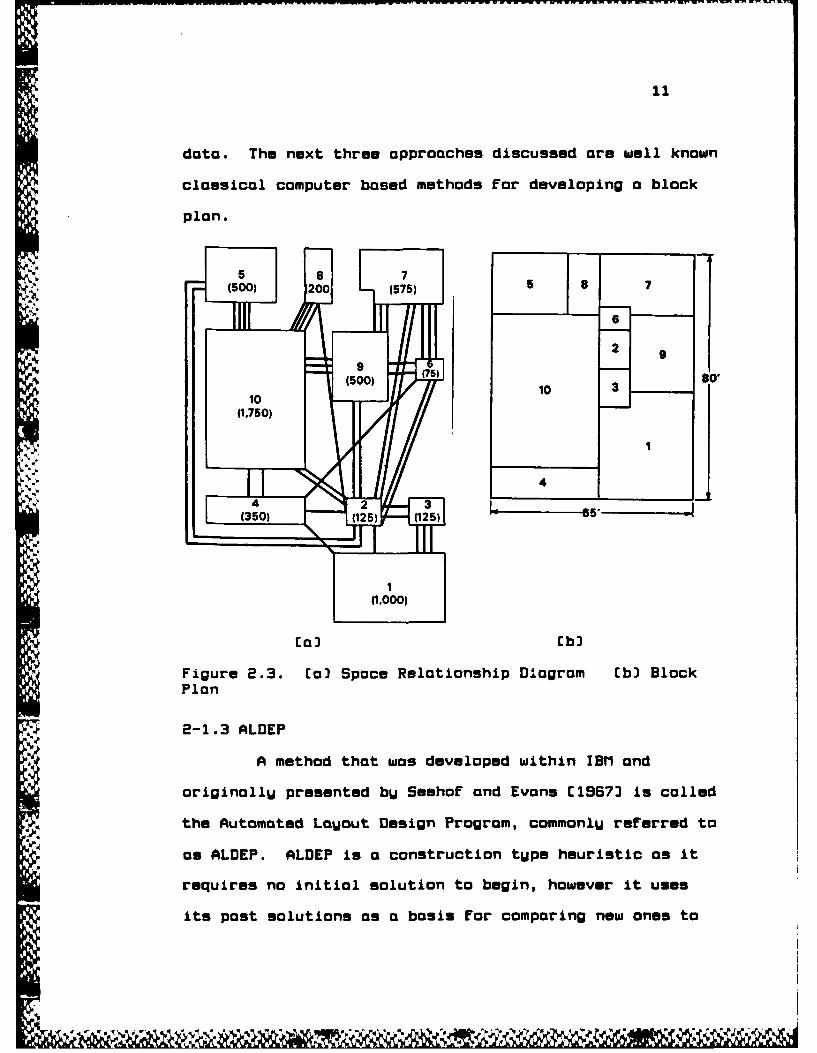
2.3 [a) Space Relationship Diagram .......... 11(b] Block Plan . . . . . . . . . . . . . . . . 11
2.4 Vertical scanning pattern used by ALDEP . . . . 13
2.5 CORELAP's placement method .......... . 15
2.6 Tetrahedron . . . . . ........... . . . . 18
2.7 Wheel Expansion . . . . . . . . . . . . . . . . 21
3.1 Initial TetrahedronCa) Adjacency Graph . . . ........... . . 32[b] Rectangular Geometric Dual . . . . . . . . 32
3.2 Insertion of facility 5 into triangle<2,3,4> (BOX)(a Adjacency Graph . . . .............. 33(b] Rectangular Geometric Dual . . . . . . . . 33
3.3 Possible Boxing Alternatives . ........... 3
3.4 Insertion of facility S into triangle<1,2,3> CCARVE]Cal Adjacency Graph . . . . . . . . . . . . . . 35[b] Rectangular Geometric Dual . ....... .35
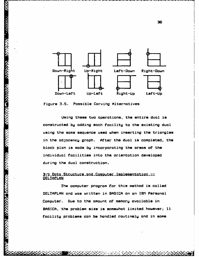
3.5 Possible Carving Alternatives . . . . . . . . . 36
3.5 Matrix representation of the rectangulargeometric dual . . . . . . . . . . . . . . . . 38
3.7 Corner Labels . . . . . . . . . . . . . . . . . 38
3.8 Matrix representation with facility 5added at <1,3,4> . ...... ... ... . 43
vi

vii
LIST OF ILLUSTRATIONS--CgotLgumd
Page
3.9 Matrix representation with facility 5added at <2,3,). . . . . . . . . . . . . . . . LIS
3.10 Correct boxing technique to prevent losingadjacencies[a] PotentiallU Wrong . . .... . . . . . . '*6C bJ Wrong . . . . . . . . .. .. .. . .. . .*6
Cc] Correct . . . . . . . . . .. . . . . . . 4*6
Cd) Wrong . . . . . . . . . . .. . . . . . . 4*6
Cel Correct . . . . . . . . . . . . . . . . . . 465
C F) Wrong . . . . . . . . . . . . . . . . . . . '16Cg) Correct . . . . . . . . . . . . . . . . . . '*5
3.11 Location of inhibitors when no facilitiesmau be added . . . . . . . . . . . . . . . . . '*9
3.12 Coordinate/Area Relationship . ..... . . 50
'1.1 Example I REL Chart . . . . . . .. .. .. .... 56
'1.2 Example I Dual . . . . . . . . . . . . 5S7
* '.3 Example I Block Plan . . . . . . . . . 5S8
'i.' Coordinate location when a Box is placedwithin the facilitU . . . . . . . . . . . . . . 60
4i.S ALDEP Laocut for ExamplelI . . . . . . . . . . 51
4i.E CORELAP Lauout for Example I . . . . . . . . . 52
'*.7 Example 11 REL Chart . . . . . . . . . . . . . 63
'i.e Example II Dual . . . . . . . . . . .. .. . .. 64
41.9 Example 11 Block Plan. . .. .. . . . . . . . 55
41.10 Edge swap improvements to Example IICal AdiocencU graph and dual after completion
of original insertion ... . .. . . . . . 66Cb) AdjacencU graph and dual after
one edge swap . . . . . , * * * * . ' 66Cc] AdjacencU graph and dual aiter*
two edge swaps . . . . . . . . . . . . . . 66[d] AdjacencU graph and dual after
three edge swaps . . . . . . . . . . . . . 57
J'l So

viii
LIST OF ILLUSTRATIDNS--CQntinuad
Page
4*.11 Example III REL Chart . . . . . . . . . . . . . 55
L1.12 Example III Dual . . . . . . . . . . . . . . . 72
L.13 Example III Block Plan with 3 facilitiesnot included . . . . . .. .. ... .. ..... 73
4j.14i Example III Block Plan complete . . . . . . . . 75
- %

LIST OF TABLES
Page
2.1 Common REL Chart Ratings, Definitions,and Scores . . . . . . . . . . .. .. ... .. 6
Lk.1 Example I Vertices and InsertionTriangles. ........ . .. .. .. ... .... 56
'1.2 Example II Vertices and InsertionTriangles . . . . . . . . . . . . . . . . . . . 53
'1.3 Example III Vertices and InsertionTriangles . . . . . . . . . . . . . .. .. .... 71
ix
,, ABSTRACT
A method for the construction of a rectangular
geometric dual from a Deltahedron based maximallU planar
adjacencU graph is given along with its computer
implementation. In addition, a method and its computer
implementation for the addition of areas to form a block
plan is given. Comparisons with output from other
computer methods is included. Possible extensions
include the construction of a rectangular geometric dual
with areas for all maximOllU planar adjacencU graphs.
.. -

CHAPTER 1
INTRODUCTION
The problem of where to locate different
Facilities within a structure is a veru old one indeed.
Whenever a building serves more than one function with
each function having specific equipment or space
requirements, choices must be made to determine the best
location for each Function. Even the simple problem of
locating a bed, fireplace, and table within a cabin
requires choice among differing alternatives. This
problem however, is not limited to location of rooms or
functions within a building. Extensions can be made to
include problems ranging from the location of different
buildings on a site to electronic components on a circuit
board. ManU approaches to this problem have been taken
A over a great span of time. One approach sometimes
- referred to as iconic, includes building models of the
different components and phUsicallU placing them in
different locations within a model of the building. The
analog approach is one that transforms the original
problem into some analogous problem and then solves this
analog problem. The solution for the original problem is
then obtained bW a reverse transformation. The approach" 1
NN,4k
2
that as of late has had bW far the most attention is the
sumbolic or mathematical approach.
This thesis deals with the extension of several
specific mathematical approaches. In particular, the
development of the spacial relationships infered bU the
results of a special class of graph theoretic methods
known as Deltahedron Heuristics.
The purpose of this thesis is to develop a
sUstematic approach to construct a rectangular geometric
dual from these Deltahedron based adjacencu graphs and
include areas to form a block plan. Chapter 2 describes
the problem as well as some past work in the area. In
*addition to a sUstematic approach for developing a
rectangular geometric dual and its block plan, a computer
implementation of this method is included in chapter 3.
Comparisons with two other computerized methods are given
in chapter k while chapter 5 contains conclusions and
suggestions for further work.
.'- .

CHAPTER 2
PROBLEM STATEMENT AND PAST WORK IN THE AREA
The general purpose of all of the lauout methods
proposed is to specify locational relationships between
facilities so as to optimize some performance criterion.
These relationships are generally of two forms, the
adjacency of facilities and the distance between
facilities. The most common objective functions used to
measure the performance criterion are maximization of
total achievable adjacencies and minimization of total
*i transportation cost. When maximizing the sum of
*adjocencies, each adjacencu between two facilities has
some specified score and the total of all adjacencies
realized represents this total adjacency score. The
minimization of total transportation cost usually assumes
that transportation cost is a function of distance and
therefore the overall pairwise distance between
facilities that have some material being transferred must
be minimized.
2=-_gsauuLi-iQute2RcoQabaa
The first formal mathematical model of the
facility layout problem was in the form of the Quadratic
3
... ... ...

Assignment Problem proposed bU Koopmans and Beckmann
[19573. This formulation takes the approach of dividing
each facilitW into some number of equal size
subfacilities, usuallU using the size of the smallest
focilitU. The task is then to assign each subfacilitU to
a location on an orthogonal grid representing the planar
site, so that the total transportation cost is minimized
and that each facilitU occupies a contiguous region. It
has been shown that this problem has no algorithm for its
solution that is polUnomiallU bounded in time and belongs
to the class of problems termed NP complete. This means
that onlW relotivelU small problems can be solved to
optimalitU using this method. Therefore, attempts have
been made to find a good heuristic to provide solutions
to this problem. Some of the well known methods are
brieflU described below.
2-1.1 Terminologw, Notation, and Definitions
The following terms and notation are defined in
the context of focilitU laWout.
UlgCg ti CW IgQUucLuti~. A construction tUpe
heuristic is one that constructs a laUout bu adding
facilities one at a time until a completed layout is
achieved.
L _iwgmt..MmuO _ lU~iS~L. An improvement
heuristic is one that requires on initial loUout as

5
input. The heuristic then improves the loUout bu some
local exchange technique until no further improvements
can be made.
L_Reultiuaubi2_gbQCt. The relationship chart,
or REL chart, is on attempt to quontifU the importance
of relationships between Facilities using closness
ratings [Muther, 19613. The closeness rating is a score,
Rij that is achieved when the two appropriate
facilities are adjacent. The ratings, their definitions,
and frequently used scores for two common methods ore
listed in Table 2.1.
LU8d1aQenQUmD. Bensrallu two facilities are
considered adjacent if thew share a common wall or
divider of some minimal tolerance length that separates
one from the other. One exception to this definition is
the criterion of ALDEP which in addition to the above
description, considers two facilities adjacent if thew
are diagonal to one another at the meeting of four walls.
Li2_tJLtLQLQuout. The initial laUout is the
lauout used for a starting point in improvement tUpe
heuristics.
L52_EgQw_9Qgt. This is a matrix, sometimes
refered to as a From-To chart, that represents the
number of trips or volume of material flow per time
period being mode from one facilitu to another.

6
£ZL_ gatUg~g. This is also a matrix however it
contains the cost to move one unit of distance between
each facility.
LOLEgLoaLQ.wgut. Since the majority of layout
planning has dealt with the design of manufacturing
structures, the building or collection of buildings is
commonlu referred to as the plant; hence the term plant
layout.
Table 2.1 Common REL Chart Ratings, Definitions,and Scores
Rating Definition Score--------------------------- ---------LUEE - OELaE-A Absolutelu necessarU 64 6E Especially important 15 5I Important 4 40 Ordinary closeness OK 1 3U Unimportant 0 2X Undesirable -1024 1
2-1.2 Muther's Sustematic Layout Planning
Muther, [19613 developed the organized approach
to plant layout known as Systematic Layout Planning
[SLP]. The three main areas of concern for this method
are Analysis, Search, and Selection as illustrated in the
method schematic shown in figure 2.1.

7
Irpu Dau arW Activiies
11111 I I
1. ~ ~ ~ S FWof . ctiit
3.lReatinsi
Figre2.. sat i L~u Plnnn Spcdr
- - - - - -

B
within the plant is collected in the form of a flow and a
cost from-to chart. Additionall, quantifiable
information about the desirobilitU of having each pair of
facilities within the plant adjacent to one another is
collected in the form of a REL chart [see figure 2.210]].
The information from these three is then used to come up
with a relationship diagram. The relationship diagram is
constructed bU arranging equal area squares that
represent each focilitU into different configurations
until one is found that has the desired level ofv\"
.* preferred properties measured bW the from-to and REL
charts [see figure 2.2[b]]. This is often an iterative
trial and error scheme that is performed manuallU with
evaluation often done verU subjectivelu and therefore
manu and possiblu preferred arrangements maw be
overlooked. Space requirements for each focilitU are
then determined as well as the total available space.
U._-5mcb. The search operation is started bU
developing several space relationship diagrams [see
figure 2.31a]. This involves combining the relationship
diagram with the space requirements and space
availabilitu to construct diagrams that have the
relationships and areas suggested during the onalusis
stage. These space relationship diagrams are then
condensed into a block plan as illustrated in figure

f9
Offices
1 5 5
3 a
Conf fm atca room e c
Parcol post I
4 Cotc n2esr 0 OriaycoeesO
6 Repairdnrvicee
Sevc area
8Receiving3
Testing
10
, General storage
Code Raon Rating DefinitionI Flow of materials A Absolutely eoir
2 Eaue of supervision E -sEedcily important
3 Common personnef I Important
4 1Contact necessary 0 Ordnary clowrnon OK
5 Convenience U Uniat
6 X Undeslirable
(II
910
~Figure 2.2. Cal Relationship Chart

10
,*, A Rating
E Rating
0 01 Rating
0 Rating
O 'V X Rating
Figure 2.2--CQgotuad. [b3 Relationship Diagram
2.31b]. This block plan is finallU combined with anU
modifying considerations and practical limitations that
are developed, to come up with alternatives for the plant
lOuout.
[2]_elamtign. The final operation is to decide
among the alternatives or to make anu data changes that
prove necesmaru and repeat the process.
All other methods presented here fit within the
general context of this procedure. AnU layout will
involve collecting data and some selection among
alternatives. The difference arises with the choice of
the method one uses to construct the black plan from the
data. The next three approaches discussed are well known
classical computer based methods for developing a block
plan.
5 8 71500) 200 (575) 5 8 7
N6 -2 9
9 (75)(5 )10 3
10(1,750)
- 4 2 3 4
(350) 115 (15 I651
I1000)
Figure 2.3. Cal Space Relationship Diagram Cb] BlockPlan
2-1.3 ALDEP
A method that was developed within IBM and
originally presented by Seehof and Evans C19673 is called
- the Automated Layout Design Program, commonly referred to
as ALnEP. ALDEP is a construction type heuristic as it
requires no initial solution to begin, however it uses
~its post solutions as a basis for comparing now ones to

see if anj improvement has been made and therefore some
improvement does take place. ALDEP divides each FacilitU
into subfacilities of some common square dimension based
upon the scale specified. A FacilitU is then chosen at
random and laUout is begun From the upper left corner of
the laoout. The subFacilities of the initial Facility
are added to the laout in vertical strips oF a specified
'sweep width' until its area is exhausted. The REL chart
is then scanned For a FacilitU that has on A or E rating
with the existing FacilitU and it is then placed in the
plaUout. As before the new focilitU is laid in a strip
fashion until its area is exhausted. The vertical
scanning nature of these strips is illustrated in figure
2.4. This addition process is then repeated until no
Facilities remain or until there ore no Facilities with
an A or E rating with the lost FocilitU added. IF the
latter is the case, a FacilitU is chosen at random and
the process is continued. The score For this method is
found using the values from REL chart. The eight squares
that surround each FacilitU are scanned and the score
recorded. After a score is recorded it is deleted from
-W the matrix to eliminate the possibilitW of including the
same adjacencW twice. The total of these values is the
score for the loaout. UsuallW the entire process is run
_y manU times with each improvement in score becoming the

13
new goal for the program to attain. Runs that do not
achieve the goal ore rejected and the entire process
stops when no improvement is mode. AlternativelU, a
collection of good solutions can be developed to provide
different options for the selection process. An example
of the output produced is included in chapter k.
"I°",
Figure 2.4. Uertical scanning pattern used by ALDEP
2-1.4 CORELAP
CORELAP is the acronUm for Computerized
Relationship Loout Planning and was developed by Lee and
Moore (1967). A number of improvements to the original
method have been added since its introduction and the
version known as CORELAP 8 will be discussed hers. As
- with ALDEP, this is a construction type heuristic. This
method begins by choosing the first facility according to
its Total Closeness Rating [TCR], calculated for focility
i by summing the REL chart scores from facilitW i to all
others. The facilitW with the highest TCR is chosen to
p~

LI
be added first, and placed in the center of the laUout.
Next o facility that has on A adjacencU score with the
first focilitU is selected. If no Facility with on A
rating is found, on E rating is searched for. If no E
rating is Found, the method continues down the hierorchU
of scores until a U is reached. If no FacilitU with a
score of U or better is found, the FacilitU with the
highest TCR is chosen. If there is more than one
focilitW with the some score, the Facility with the
highest TCR is chosen. The some tUpe of search is
employed at all sucessive steps with the search started
bU looking Far a FacilitU with an A odjacencU to the
first facility. If none is found, on A adjacencU with
the second facilitU is desired, followed bU an E with the
"first, an E with the second, on I with the first, etc.
All facilities are added to the exterior of the existing
arrangement and ore rectangular in shape. TheU are
'placed in a position that will Uield the highest
placement rating and boundorU length,where the boundarU
length is the length of the boundaries common to the new
FacilitU and the existing layout. Some different
configurations possible ore illustrated in figure 2.5.
The placement rating is the sum of the weighted ratings
between the department being added to the layout and its
neighbors if it is placed there. The weights are

assigned to the adjacencw ratings bU the user. Therefore
the score used for the TCR is not necessarilu the some as
that used to score the placement of each facility within
the laUout. An example of the output from this method is
also included in chapter 4.
I-- 3 -- 4-- 2 -
-. T3 22
3]33
3 4 22
Figure 2.5. CORELAP's placement method
2-1.5 CRAFT
CRAFT is an improvement tUpe heuristic and was
introduced bU Armour and Buffa (1563). In addition to
differing from ALDEP and CORELAP in the tWpe of heuristic
used [construction versus improvement), CRAFT employs a
entirelU different method for evaluating a lo~out.
V

16
Unlike ALDEP and CORELAP, CRAFT attempts to minimize
transportation cost where this cost is expressed in terms
of distance traveled. This is therefore an attempt to
provide a solution to the DAP mentioned earlier. As an
improvement heuristic, CRAFT requires on initial laWout
in order to opplU its improvements. The score for a
lauout is the cost per unit distance (cost data] to move
an item, multiplied bU the rectilinear distance between
focilitU centroids, multiplied bU the number of trips
required [flow data], for all pairs of facilities in the
laUout. The next step is to consider the exchange of two
or three facilities within the loUout. The possible
combinations include 13 two-waW interchanges, 23
three-waW interchanges, 3] two-waU followed bU three-wag
interchanges, 4] three-wag followed bU two-waU
interchanges, and 53 the best of two-woU and three-waU
interchanges. Exchanges of facilities are onlU possible
if the facilities are adjacent to one another or if their
areas are equal. The search for the best of these is
done bU interchanging the centroids which are used in the
distance calculations as an estimate of the actual cost.
The best exchange, lowest score, is then made and
centroids recalculated according to the new shape of the
facilities. If a savings still exists the process
continues and if not the old loout is maintained and a
17
different interchange is attempted. When no improvements
can be made the process stops. A drawback with the
method is that there appears to be no consistent method
for the physical exchange of adjacent facilities of
varying areas.
e-2.1 Terminology, Notation, and Definitions
The following terminology and notation is
defined:
El2lL-_Qb. A graph is a pair of sets (V,E) where
V is finite and not emptu. The elements of U are called
vertices and the elements of E are distinct pairs of
vertices called edges. If there is no direction
associated with the edges, they are known as undirected
edges. If all edges are undirected, the graph is said to
be an undirected graph.
L 2_e£gbtmdtgb. A graph that has a weight,
We, assigned to each edge, e, is known as a weighted
graph with We usually being an element of the positive
real numbers.
L_CQgget_QCQgb. A complete graph, denoted K4.
is one in which all pairs of vertices are joined by an
edge. A complete undirected or summetric graph has
En~n-133/2 edges.

15
£ ._ aZDar_ Brb. A graph is said to be planar if
it can be drawn in the plane such that no two edges
intersect except at a vertex to which both are incident.
Lg1-0aia±lug- ngrg.rgb. A graph in sold to be
maximallu planar if it not possible to add an edge and
still maintain planaritu. Due to the fact that oll faces
of a moximallU planar graph ore triangles, a maximallu
planar graph is often known as a triangulation. A
loximallU planar graph contains 3n-6 edges CEuler, 1752.
LfijmtrQbmoudQ. A tetrahedron EKI*J is a complete
graph on four vertices which is also maximallu planar
Csee figure 2.6].
-
Figure 2.6. Tetrahedron
V LZI Vlubtod(on. A deltahedron is a graph that is
constructed bU beginning with a tetrahedron and adding
vortices bU thm insertion of an additional vertex into a
'&a& a

15
triangle and adding edges from the new vertex to sach of
the three vetrices that define the triangle. Due to this
fact a deltohedron must contain at least one vertex of
degree three {three edges incident with it).
-~b A maximallU
planar adjacencU graph is a maximallU planar graph whose
edges represent adjacencU between pairs of facilities.
121cgmkir±_ugl. The geometric dual of the
maximallW planar adjacencU graph is a spacial
representation of the facilities that ore represented bw
the vertices of the graph. The edges of the graph
represent the adjacencU of two facilities in the dual.
If a graph is maximallU planar then its dual is also
maximallU planar or in other words no further adjacencies
in the dual can be established without violating the
planaritU of the dual [WhitneU, 19313.
LlQbgn~g~gUiguwutDgm _DUgL. For this
discussion, a rectangular geometric dual is a geometric
dual that contains onlU rectangular, L and T shaped
areas.
All graph theoretical approaches presented here
are of the construction tUpe. One starts with a complete
graph on N vertices corresponding to a REL chart with
zero weight edges added if nocessarU, and attempts to
find a maximallU planar subgraph on the complete graph
that has maximum weight since without loss of goneralitU,

20
with nonnegative weights, an optimal solution will be
maximallU planar. The problem of starting with the
complete graph and deleting edges until it is maximallU
planar is a relativelU difficult and verU time consuming
problem due to the methods required to check for maximal
planaritU. The methods shown here use construction
techniques that start with either a graph that is not
maximallU planar and iterativelU build it up until it is
maximallU planar or a graph that is maximallU planar and
then add vertices and edges to it in a specific manner so
that it will alwaUs remain maximallU planar. Several of
the methods start with a complete graph on four vertices,
KL. There are basicallU two methods for determining
which four vertices should make up this initial
tetrahedron. The first is the greedU approach which
finds the highest weight tetrahedron among all
possibilities. The other is formed bU first summing the
scores of all columns from the square adJacencU matrix.
The vertices are then sorted in non-increasing order
according to these column sums. Then the vertex with the
highest adjocencu rating to all other vertices is chosen
first. It has been shown (Giffin, 1S5B1 that there is
empiricallU no clear difference in final triangulation
solution qualitU for either starting procedure. The
objective of all methods that follow (with the exception

21
of Super Deltahedron] is to maximize the adjacencu score
where the values of having two facilities adjacent ore
the some as those used in ALDEP.
2-2.2 The Wheel Expansion Heuristic
The Wheel Expansion Heuristic (Eades, Foulds, and
Giffin, 1982) begins with on initial tetrahedron and uses
an operation known as a wheel expansion to add sucessive
vertices to the graph. It has been shown that the wheel
expansion operation is sufficient to form all maximally
planar graphs possible if the starting point is
K.. An example of wheel expansion is illustrated in
figure 2.7. The choice of vertex and location for
expansion involves finding the vertex and expansion point
that has the highest increase in adjacencu score.
Figure 2.7. Wheel Expansion
2-2.3 The Greedy Heuristic
The idea behind the Greedu Heuristic [Foulds,
Gibbons, & Giffin, 1985) is very straight forward.
First, all edges are listed so that all edges with A
values are first followed by those that have a value of E

etc. Next an edge is token from the top of the list and
it becomes the first edge of the subgraph. The edges ore
then sequentiallU taken from the top and added to the
graph as long as planoritU is not violated. When 3n-5
edges have been added the subgraph construction is
completed. It is noted that this method requires an
explicit planaritU test [Hopcroft & Tarjan, 1973.
2-2.4 The N-Boundaru Greedu Heuristic
The N-boundarU GreedU Heuristic [Giffin & Foulds,
1986 is an extension of the GreedU Heuristic that
includes benefits to the final score for not onlU
facilities that are immediatelU adjacent to one another
but for facilities that are k facilities apart from each
other. In addition to the normal adjacencU matrix
required, additional matrices that give values for having
two facilities 2, 3, 4, etc. facilities apart are
required. Under the assumption of approximatelU equal
areas, normallU a score is higher if a facilitU is fewer
facilities distant. Due to this fact when adding a
FacilitU the shortest path to reach all other facilities
must be calculated in order to find an appropriate
addition.

23
2-2.5 An Oriented Graph Theoretic Heuristic
A paper bW Roth, Hashimshon, and Wachman (19823
suggests a method for turning a graph into a rectangular
floor plan, again requiring the development of a planar
odjacencu graph. The adjacencies have no degree of
desirobilitu in this method, onlU a requirement for their
presence or absence. These incidence requirements ore
converted into a planar graph bU the subtraction of edges
or the addition of dummW vertices. This planar graph is
then split into two subgraphs representing north south
and east west orientations bU a coloring technique and
dimensions ore calculated using the PERT algorithm. From
this technique, several alternative plans are generated
for further evaluation. A requirement for the dimension
calculations is the orientation of certain facilities to
given directions. These calculations use the PERT
algorithm to find the critical path from the north side
of the building to the south as well as a critical path
from the west to the east and therebu determine the
necessoru dimensions.
F.:3-Qatban -Daaemd-Ifltbodu
The graph theoretic heuristics above have a major
disadvantage compared to the Deltohedron based heuristics
that follow. This disadvantage is that as Wet there is
no systematic method for finding the rectangular
Vi

geometric dual to the adjacencU graphs generated. The
main purpose of this thesis is to describe such a
sUstematic approach for the deltahedron based heuristics.
A feature that all of the deltahedron approaches
have in common is that they begin with an initial
tetrahedron. Short descriptions of the deltahedron
approaches follow.
2-3.1 The Deltahedron Heuristic
The Deltahedron Heuristic [Foulds and Robinson,
1978] sequentiallU adds a vertex into the triangle of the
existing graph that will give the greatest increase in
adjocencU score. This increase in score is calculated bU
summing the weights of the three edges used to connect
the new vertex to the existing graph. The order that the
vertices are added is the continuation of the column sum
ordering used in the initial tetrahedron selection or the
selection at each iteration, of the vertex and triangle
that will Uield the greatest increase in score among all
choices (sometimes referred to as the greedU orderJ.
This method is described in greater detail in chapter 3
since it is used to generate the adJacencU graphs used to
demonstrate the development of a block plan from a
Deltahedron based method.
.4 - . 3

25
2-3.2 The Improved Deltahedron Heuristic
The Improved Deltahedron Heuristic [Foulds and
Robinson, 197B] uses the solution obtained with the
Deltahedron Heuristic as input. This graph is examined
to see if anu improvements con be made, in the form of
edge swapping or vertex relocation. In most cases, if an
edge is deleted From the graph, a quadrilateral is
Formed. The edge that was removed formed a diagonal in
this quadrilateral. IF the edge that is identified with
the other diagonal is added a new graph is formed that is
also maximallU planar. If the score is increased bU this
swap, it is performed, and iF not, it is ignored. All
possibilities are examined and when no improvements can
be made, the process stops. In some specific instances
after an edge is removed, the one that would be added is
alreodU a part of the graph. These situations are either
ignored, or a well defined sequence of equivalent swaps
made.
2-3.3 The N-Boundary Deltohedron Heuristic
As the N-Boundaru GreedU Heuristic is an
extension of the GreedU Heuristic, so too is the
N-BoundarU Deltahedron Heuristic [GiFFin & Foulds, 1986]
the same tUpe oF extension to the Deltahedron Heuristic.
An increase to the score of the N-Boundaru Deltohedron is
determined bW the adjacencies of facilities 2, 3, 4, etc.
: *% *~'a-v~ ~ '-a ~ * ."*~~~'

facilities distant in addition to the immediate
adjacencims scored in the Deltahedron Heuristic. This
heuristic begins with the same initial tetrahedron
selection method as the Deltohedron method and adds to it
by choosing the vertex that will yield the highest
increase in score for adjacency or near adjacency to all
other facilities. As with the N-BoundarW GreedU
Heuristic, an update version of a shortest path algorithm
must be run at every iteration.
2-3.4 The Super Deltahedron Heuristic
The Super Deltahedron Heuristic [GifFin & Foulds,
1985) is fundamentally different from the other graph
theoretic methods in that its objective function is not
the maximization of total adjacency scores; instead it
attempts to minimize transportation costs much like the
QAP formulation or the CRAFT method. The method again
starts with the initial tetrahedron selection process
used in the Deltahedron method since maximizing the
proximity of four facilities with high mutual flows
should provide reasonablU low transportation cost. The
order of insertion is either the column sum or the greedy
approach used in the Deltahedron method. The triangle
selected for insertion is the one that minimizies the sum
of the product of the cost per unit distance traveled,
the number of trips per time period, and the distance

~27
between two facilities, over oll pairs of facilities
contained in the adjacencU graph. The shortest path
routine is also required in this method for the
computation of pairwise facility distances. The distance
traveled between two facilities x and u is approximated
bu the sum of half the square root of the area of x, the
sum of the square root of the area of all Facilities on
. the shortest path from x to u, and half the square root
of the area of W. This metric assumes that all facilities
are squares with side length equal to the square root of
the area, the travel between two facilities is between
centroids of the two facilities, and that all travel is
done in a rectilinear fashion. These assumptions are not
verW likelW in the final block plan; however, theW are
onlW designed to give a ranking among triangles for the
insertion process.
.%
_i
i

V
CHAPTER 3
RECTANGULAR GEOMETRIC DUAL ANDBLOCK PLAN CONSTRUCTION
The Following terminology and notation isdefined:
LL Z exO . A point on the adJacencW graph at
which edges converge is known as a vertex.
4 L]_-dge. An edge is a line connecting two
vertices on the adjacencW graph.
J32_AnverttinQec. The insertion order is the
order in which the vertices are added to the initial
tetrahedron to Form the completed adjacencU graph.
LU2_He. gagUOt _agMUtr. _QUQg . A rectangular
spacial realization oF vertices and their adjacencies
represented in the adjacencU graph.
"52_Ngod. Each node is a point in the dual which
has a one-to-one correspondance with a triangle Formed bW
three vertices and three edges of the adjacencW graph.
L5LWgIL. A wall is a line that connects two
nodes in the dual. Each wall has a one-to-one
correspondance with an edge in the odjacencU graph.
EZ2_EJaQeLn. When a FocilitU i is added to the
dual, a portion of the dual is renamed to represent i.
-'." 28
II2

The designation being replaced is called the Facility
that i was placed in. IF another facilitU J was added so
that a portion of Facility i is renamed, facilitW J is
placed in i, not the original FacilitW.
-£r _ 2rr[ . The right angle sometimes required
to connect two nodes of the dual in a rectangular Fashion
is called a corner.
.LL.8diti.._5ugumnGu The addition sequence is
identical to the insertion order, however it refers to
additions to the dual not the adjacencW graph.
L1QJ-goe._EQ. OgQjD3. Node expansion is the
redesignation of the structure surrounding a node in the
dual when a FacilitU is added at that node.
L12lnbbi.toc. An inhibitor is a dummU node
added to the dual matrix to prevent the loss of
adjacencies when areas are later added to the dual to
Form the block plan.
12EIN. N is the number of Facilities or
vertices.
- [ The combination of symbols <i,j,k>
-' represent the triangle Formed bU vertices i, J, and k
with edges iJ, jk, and ki.
The Deltahedron Heuristic seeks to Find a
- maximallW weighted maximallU planar adjacency subgraph of
"S!

30
o complete adjacencU graph. The method used here is the
simplest of the variants of the Ueltohedron Heuristic.
The first step is to construct the NxN matrix of Rij
-h values. The scores for each Rij are entered in the
matrix Wij. The columns are then summed and reordered in
nonincreosing order bW these column sums with the
exception of facilitU 1 which is alwaus the exterior.
* For ease of discussion, suppose that the vertices were
initiallU in nonincreosing order of column sums and
therefore their order is 1, 2, ... ,N. This is now
refered to as the Insertion Order. The first four
verticies are combined to form the complete graph on four
verticies X4 which comprises the Initial Tetrahedron Csee
figure 3.la]]. The vertices are then added according to
the insertion order. Consider the insertion of vertex r
into triangle (i,j,k>. The benefit to the total score
is the sum of Wir + Wjr + Wkr. Therefore r is chosen to
maximize this sum over all available triangles. After
adding vertex r into triangle <i,j k>, this triangle
(i,j,k> is replaced bU triangles (i,j,r>, <i,k,r>, and
<J,k,r>. The next vertex is then selected and inserted
into the triangle that will achieve the greatest benefit.
If there is a tie among several triangles for this

31
maximum benefit, several different strategies can be
incorporated. One such strategU is arrange them
lexicographicallU and chose the First one. Another is to
chose one of the possible triangles randomlU and this
approach is taken here to avoid a large concentration of
insertions in one section of the graph.
:3_gtngnigrb,.gg[_boaggigwitrmg..Uug1
The method used for constructing the rectangular
geometric dual, hereafter referred to as the dual, is
limited to the class of adjacencu graphs that can be
constructed using onu variant of the deltohedron
heuristic. The only input required is the triangle
insertion order. The process begins with a rectangular
representation of the dual corresponding to the initial
tetrahedron. This is shown in figure 3.1. The
facilities are numbered as shown with facilitU 1 being
defined as the exterior. It should be noted that each
node of the rectangular geometric dual has three and onlw
three edges incident with it. Each node has a one to one
correspondence with a triangle that exists in the
deltahedron at the current stage of the adjacencu graph
construction. If a EncilitU is added to the rectangular
Kgeometric dual bU expanding about one of these nodes, itsI odjacencies will correspond .xactlU to those in the
odjacencU graph.
I C

32
1
2
<1,2,3> <2,3, > 1,2, >
3 4 , ,4(1,3, 4>
AdjacencU Graph Rectangular Geometric Dual[a] EbJ
Figure 3.1. Initial Tetrahedron
There are two waUs that a facilitu maU be added
to the dual with the decision being made bU inspection of
the nodes in the dual that are onlu one edge distant. If
there are no corners that are between the node of
interest and anu of the three adjacent nodes, then the
facility is added bu a BOX operation. If there is a
corner immediatelU adjacent to the node of interest, a
CARVE operation is used. An example of each follows.
3-3.1 Boxing
From inspection of the initial block plan, figure
3.1[b], it can be seen that the onlU node that has no
corners adjacent to it is (2,3,4> therefore consider the
insertion of facility 5 at this node. From the adjacencu
Ax

graph in figure 3.21a], it can be seen that when facilitU
5 is inserted into <2,3,4>, the triangle <2,3,4> is
replaced bU three triangles, namelu <2,3,5>, (2,',5), and
(3,5,S>. Figure 3.2(b] illustrates this insertion and
the necessorU relabeling.
1
3 < <1, 3, L
Cal Cb]
AdjacencU Graph Rectangular Geometric Dual
Figure 3.2. Insertion of facilltW S into triangle,2,3,4> CBOX]
~Since focilitU 5 replaced a portion of facilitu 3, this
~is defined as placing focilitg 5 in facilitu 3. This
operation is called a "box" f~or obvious reasons. The box
:z could also be flipped to the opposite side of the wall
w separating facilities 3 and 5f. The choice is arbitrarU,
however it does affect the orientation of the block plan

34
from the decision point on. For anu given location this
flipping is not alwaUs possible for other reasons that
will be shown later. Four orientations of the boxing
operation arm possible and for implemmntation purposms
are defined as left-down, left-up, right-down, and
right-up [see figure 3.3].
T orR 4rilE
Left-Down Left-Up
ororiL
Right-Down Right-Up
Figure 3.3. Possible Boxing Alternatives
3-3.2 Carving
Now consider instead, the insertion of facilitU 5
into triangle <1,2,3>. This could be done as a boxing
operation [right and down] however this would
unnecessarilU create an "L" shape which is not as
desirable as a rectangle. This is avoided bU an
operation called a "carve." Figure 3.4 is an
illustration of this operation.
• . %.'

35
;l 1
<1,2,S> <2,3,5> <2,3,4> <1,2,4).
A15 3 L
3 4 <1,3,5> <1,3,4>i [a Rctngla [b]
Adjacencu Graph Rectongulor Geometric Duol
Figure 3.4. Insertion of facilitU S into triangle<1,2,3> [CARVE)
The some general triangle replacement is done as above.
The eight orientations for the carve operation are shown
in figure 3.5 along with their designations. These
designations indicate first the direction in which the
corner is encountered followed bU the direction not cut
off bU the corner. A carve operation cannot be flipped
to the opposite side of a wall like the box since there
is no corner to "carve" towards. Boxing might be an
alternative; however, as will be shown later there could
be a problem with maintaining the required adjacencies in
the dual when areas are introduced.
Ra
36
Down-Rigt Up-Right Left-Down Right-Down
Down-Left Up-Left Right-Up Left-Up
Figure 3.5. Possible Carving Alternatives
Using these two operations, the entire dual is
constructed bW adding each facilitU to the existing dual
using the same sequence used when inserting the triangles
in the adjacencu graph. After the dual is completed, the
black plan is made bW incorporating the areas of the
individual facilities into the orientation developed
* during the dual construction.
N.
OELIMEL8N
) The computer program for this method is called
DELTAPLAN and was written in BASICA on an IBM Personal
Computer. Due to the amount of memoru available in
BASICA, the problem size is somewhat limited however; 11
facilitu problems can be handled routinelU and in some
4y

37
cases it will run completelU with as manu as 22
facilities.
3-k.1 Initialization
To facilitate an eosilw envisioned and
manipulated representation of the dual, a matrix of
alphanumeric strings is generated that contains the
elements common to all initial block plans. As con be
seen in figure 3.6, all of the initial triangles are
represented as six character strings. For example
triangle <1,2,3> is represented bW 010203. The walls are
represented bW a single dash "-" and the interior of a
focilitU bW a two digit numerical string for example "Ol"
for FocilitU 4 and "12" for facilitU 12. Since each
corner is adjacent to onlW two facilities the first two
elements of the string are letters that represent the
orientation of the corner [see figure 3.7.) The two
corners in facilitU 2 [upper left and upper right
corners] are not used as no facilities are added within
facilitW 2 and therefore are represented bU "000102".
'4
_ o~\. ~ V
3.
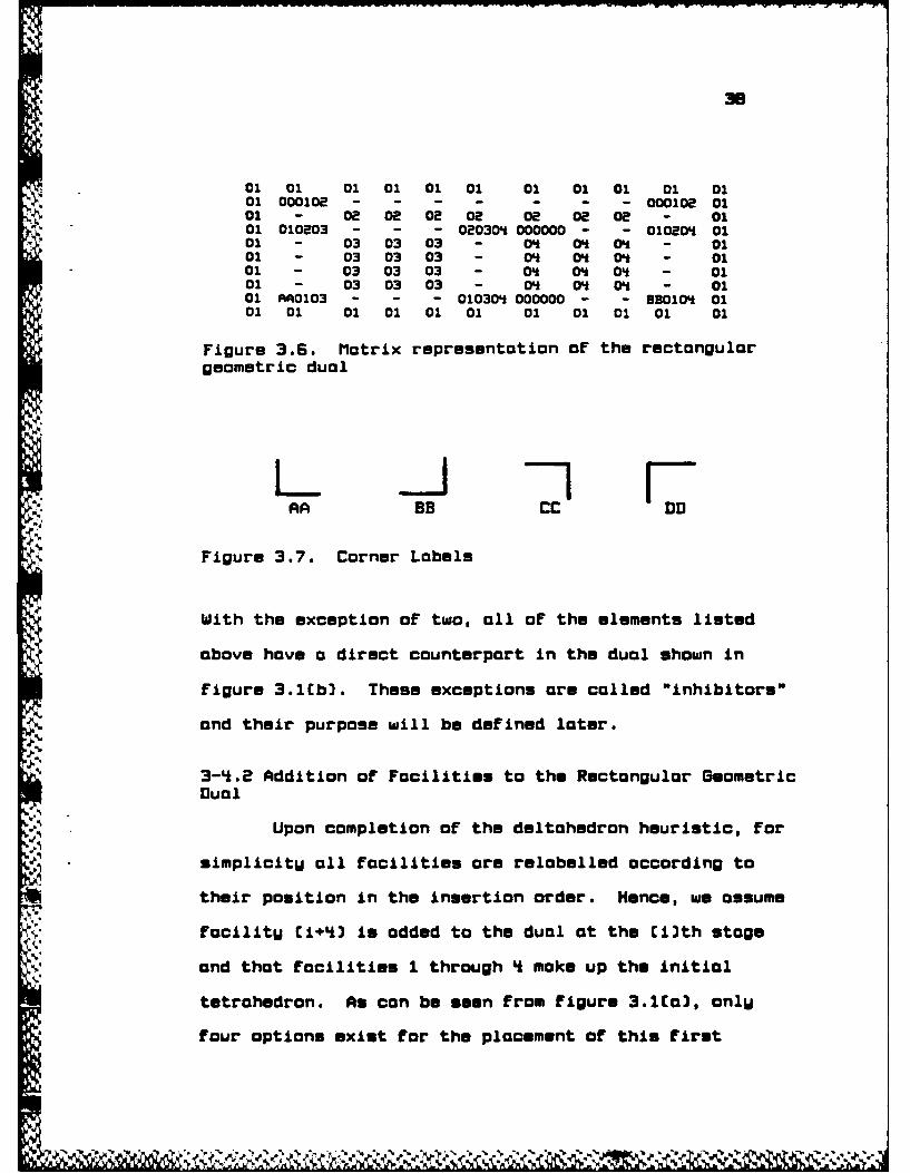
01 01 01 01 01 01 01 01 01 01 0101 00010e - - - - - - - 000102 0101 - 02 02 02 02 02 Oe 0E - 0101 010=03 - - - 020304 000000 - - 01020 0101 - 03 03 03 - 0* 0h 0 - 0101 - 03 03 03 - 0* 0* 0* - 0101 - 03 03 03 - 0* 0* 0* - 0101 - 03 03 03 - 0* 0* 0* - 0101 AA0103 - - - 010304 000000 - - BB0104 0101 01 01 01 01 01 01 01 01 01 01
Figure 3.6. Matrix representation of the rectangulargeometric dual
ARA BB cCC
Figure 3.7. Corner Labels
With the exception of two, all of the elements listed
above hove a direct counterpart in the dual shown in
figure 3.lb]. These exceptions ore coiled "inhibitors"
and their purpose will be defined later.
J " 3-4.2 Addition or Facilities to the Rectangular GeometricDual
Upon completion of the deltohedron heuristic, for
Ssimplicitu all focilities ore relobelled according to
their position in the insertion order. Hence, we assume
focilitU Ci+4] is added to the dual at the Ci~th stage
and that facilities 1 through 4 make up the initial
tetrahedron. As can be seen from figure 3.1[a], onlU
four options exist for the placement of this first

39
facilitU and the output of the deltahedron heuristic used
to generate the insertion order has chosen the
appropriate one. A search is then made to match the
triangle in which facilitU S is to be inserted, with its
identical element in the dual matrix. A sort routine is
included in the program to insure consistent ordering of
the three two digit pairs within each element. Since a
search of the whole matrix is rather time-consuming, a
table is constructed which contains each possible
insertion triangle along with its coordinates [I,J] in
the matrix.
LL2_ugrgbIng. Before the search is done, all
flags (described below] and all direction indicators are
set to zero. Starting at the coordinates [I,J], a search
is performed to the left to identifU the structure of the
dual to the left of the triangle in question. A variable
"L" is used to keep track of the search and is initiallu
equal to J. L is decrimented bU one and the element with
coordinates [I,L] is examined. If L is less than 1, the
border of the matrix has been reached and the left
direction is "unusable." An unusable direction means
that no box or carve operation is possible in this
direction. In the program this is accomplished bU
setting LFLAGO-1. If the element is a dash, "-", the
search continues with the next element. If a six digit

N ',0
element is found, the search stops. If the first digit
of the element is "A" or "D" (these are the onlU possible
corners when searching to the left], LFLAG1-1 or 4
respectively. This flog indicates whether a box or a
carve operation is appropriate where a tupe A corner is
indicated with a 1, tgpe B with a 2, tupe C with a 3, and
tUpe D with a k. The presence of a "000000" element
indicates a inhibitor ond the inhibitor flog LFLAG2 is
set to 1 (inhibitors ore described later in this
chapter.] If L-J-1 or J-2, the left direction is again
unusable since there are not enough elements between J
and L to define o new facilitW. After the search to the
left, a similar search is done in the right, down, and up
directions.
Lgug_ Qmgjj_ Q. The flogs LFLAGO,
LFLAG1, RFLAGO, RFLAG1, DFALGO, DFLAG1, UFLAGO, and
UFLAGi are compared to the set of values required for
each carve operation to see if it is possible to carve.
For each carve operation three flags must be set to
specific values. For example, to carve left-up the
corner encountered in the left search must be a tupe A
* [LFLAG1-1], the left direction must be usable (LFLAGO-O]
and the up direction must be usable [UFLAGO-O. If none
of the above conditions ore satisfied, the flags required
for the boxing operations are checked. In this case
there are onlW two flags required for a box operation.
C-.. -zk

4.1
For the box left-up operation the flags needed are the
* same as for the carve left-up [LFLAGO-O and UFLAGO-O3
except there must be no corner present so the left and up
corner indicators must be 0 CLFLAG1-O and UFLA61-O).
L31_gryiDg. The left-up carving operation will
be used here for description purposes. However, the some
general format applies to all eight carving operations.
Consider the insertion of facilitw 5 into triangle
<1,3,4>. An inspection of figure 3.6 gives the structure
surrounding 010304 and indicates that a left-up carve is
appropriate. The coordinates [I,J] of 010304 are
determined and will become the location of one of the new
nodes of facility 5. In this case L equals the J
coordinate of AAO02, U equals the i coordinate of 020304
and both the right and down directions are unusable.
Next, the coordinates [I,Jl] of the point diagonallW
across the new facility from [IJ] are determined. If
the element which determines U is not on inhibitor, Ii is
half woU between I and U. If it is, I-U+1, since if on
inhibitor is present, the element above has an unusable
down direction. A carve that goes onlu half waw up
wastes the entire portion above the carve and is then
lost to further insertions. However, if the carve goes
as close as possible to the node above, onlW a few
elements in the matrix ore lost. The J coordinate J1 is

------------ .- r- - I - IV' .J -WV.p 4 U~ - 'r - *r - e - r .r r
equal to L. In order to determine the orientation of the
facilities which border the new one, three more variables
are set. In this case they are LS-"01", US-"03", and
RS-"04", and they are taken from the matrix by
determining which Facilities are to the left, right and
above the new Facility. These three pairs along with the
number of the new Facility (FACS] are combined to Form
the Four new nodes in the matrix. The upper right node
is US + RS + FACS C030405] with coordinates [I1,J], while
the upper left node is LS + US + FAC$ C010305) at
[I1,Jl]. The lower left element is "AA" + LS + FACS
(AAOlOSJ at [I,Jl] and Finally the lower left node is LS
* + RS + FACS C010(5) at [I,J]. The walls are then
inserted by renaming the elements between each node on
the perimeter of the new Facility with .... The interior
of the Facility is then Filled in with FACS or in our
case "05". Two inhibitors are then added in place of the
elements immediately above the upper left and upper right
nodes. The purpose of these is described later. Figure
3.8 shows the matrix with Facility 5 added at <1,3,4>.
• im
t'S~PS

43
I"
4. 01 01 01 01 01 01 01 01 01 01 0101 000102 - - - - - - - 000102 01
-01 - 02 02 02 02 02 02 02 - 0101 010203 - - - 020304 000000 - - 010204 0101 - 03 03 03 - 0* 04 04 - 0101 - 03 03 03 - 0* O 04 - 0101 - 03 03 03 - 04 04 04 - 0101 000000 03 03 03 000000 04 O 04 - 0101 010305 - - - 030405 04 01* 0 - 0101 - 05 05 05 - 04 04 Ot - 0101 - 05 05 05 - 0 01* 01 - 0101 AAO05 - - - 01005 000000 - - BB010 0101 01 01 01 01 01 01 01 01 01 01
Figure 3.8. Matrix representation with facility S addedat <1,3,4>
Two additional items are required for the area
calculations that begin following the completion of the
dual. The first of these is the operation with which the
facilitU was added. In the above example, the operation
is carve left up therefore the variable OPERS[S]
4 [operation for facilitU 5) is designated "CLU". The
other requirement for the area calculations is the number
of the facilitW in which the new facilitU was placed.
The variable for this is PLINS, and its value in the
above example is 3 since the 05 elements replaced 03
*, elements.
EL11-_oxiig. The box operation is accomplished in
much the same manner as the carve. For this description,
the addition of facilitW S at <2,3,4> will be used. TheS.
surrounding structure here indicates that a box left down
operation is appropriate. Notice that without the
inhibitor to the right of 020304 a box right down would.4
.
! * *

also be possibilitU. As noted earlier, this topic will
be discussed later. As in the carve operation, the
coordinates [I,J] of 020304 are determined, as well as L
and D, in this case, L is the j coordinate of 010203 and
D is the i coordinate of 010304. Since neither of these
is an inhibitor, I1 is half waU between I and D and J1 is
half wau between J and L. IF the node to the left had
been an inhibitor, J1 would have been L+1 and if the node
below was and inhibitor, Ii would have been D-1. The
same matrix conservation reasoning applies here as in the
carve operation. The variables LS, US, and RS are set as
described above in order to define the new nodes. Here
L$-"03", US-"02", RS-"04", and FACS is again "05". The
new nodes are 020305 for the upper left, 020405 for the
upper right, 03040S for the lower right, and AA030S for
the lower left element. As before, the walls are
inserted, interior of the new facilitU is relabelled,
OPERSS] is set to its value of BLU, and PLINS]5) is set
to its appropriate value which is 03. A representation
of this is given in figure 3.9. It is noted here that as
above there are two inhibitors, one to the left of the
* upper left node and one below the lower right node. The
purpose of the inhibitor is defined next.

01 01 01 01 01 01 01 01 01 01 01 01 0101 000102 - - - - - - - 000102 0101 - 08 08 2 0 0 08 O 02 80 - 0101 010803 - 000000 020305 - - OIMOS 000000 - - 010M0Ot 0101 - 03 03 - 05 05 - 04 04O 0 - 0101 - 03 03 - OS OS - 0 0 O - 0101 - 03 03 AA030S - - 030405 04 0't 0 - 0101 - 03 03 03 03 03 000000 0 00 O - 0101 - 03 03 03 03 03 - 0 00 O' - 0101 - 03 03 03 03 03 - 04 0t 0O - 0101 AA0103 - - - - - '010304 - - - BB010 0101 01 01 01 01 01 01 01 01 01 01 01 01
Figure 3.9. Matrix representation with facility 5 added
at 42,3,&P
1L91-_oblbitor . The purpose of inhibitors is to
block the insertion of facilities at certain locations
that could possiblu destrou on existing adjacencu once
areas are added. Consider the addition of focilitU 5 to
(,3,4) and the subsequent addition of facility 6 to
<2,'<,5>. If facilitu 5 were added as described above, it
is noted that the coordinates of 020405 are the same as
were the coordinates of 020304. With the inhibitor
present, as is shown in figure 3.9, the only possible
operation is a box left down. However, if the inhibitor
were not present, a right down box would also be
possible. If the box left down for facility S wure
followed bU a box right down for facilitu 6, the result
would be as is shown in figure 3.1OCa1. The problem
arises when areas are introduced. If the area of
facility 6 is larger than that of facilitu 5, the
adjacencu between facilities 4 and 5 is lost and an
adjacencu between 3 and 6 is gained as is shown in figure

2 2 2
F s J is j FLh-Si
3 4 3 Lf 3
Potentiolly Wrong Wrong CorrectEo[3 [b3 [c3
7S7 ---,5
3 7 -- 3
I LI 6 6---
Wrong CorrectCd3 C.)
2 P
5 75
3 3
Wrong CorrectrC 3
Figure 3.10. Correct boxing technique to prevent losingadjocuncies

4*7
3.101b]. In this case the block plan would not reflect
the adjacencies required bu the adjacency graph. The
block plan that does reflect the required adjacencies
regardless of areas is shown in figure 3.10Cc3.
Another example of inhibitors using the carve
operation is illustrated in figures 3.10 [d) and Ce].
Here a carve for facilitW 5 at 010204 is followed by a
carve at 010405 for facilitu 6. With no inhibitors, the
problem here is the addition of facility 7 at 020405 and
the two options of box left down and box right down. As
is seen in figure 3.10[d3 the box left down destroys the
adjacency between 4 and S and creates an adjacency
between 6 and 7; however, at this stage facility 7
should onlW be adjacent to 2, 4, and S. The box right
down is appropriate here and figure 3.10(e] illustrates
the block plan which the inhibitors require.
A final example is shown in figures 3.10 (F)
and [g]. In this case facility 5 is added at 020304
Followed by a carve for facility 6 at 030405. When
facility 7 is added at 020305, the same problem presented
in figure 3.11 arises again. With no inhibitors the
*block plan could end up as in figure 3.10(f], whereas
inhibitors require the block plan in figure 3.10Cg].
The initial choice of location for the
inhibitors to the right of 020304 and 010304 is
arbitrarW. Placement of both on the left would perform
Y~si~y $k

Just as well but it should be noted that theu must both
be on the same side or theU would create the veru
problems theu are designed to eliminate.
The results below follow from the operations as
defined.
L52lIbwgam-_. No more than one carve can be
done within anu facilitU. PROOF -- In order to carve
there must be a corner towards which one carves. After
one carve is done, there is no corner left in the
original facilitU therefore the condition required to
carve does not exist and no further carving can be done.
MZiI-begrem_. No more than three facilities maw
be placed within anU given focilitU i. PROOF -- All
facilities, with the exception of 2, begin as boxes.
Even if a facilitU is added bg a carve operation it
contains one corner and therefore has the some structure
as a box. As such, there are three nodes which can be
expanded about to form new facilities. Each time a
facility is added, due to the nature of the inhibitors,
none of the new nodes created allow the addition of a
focility within focilitU i. An illustration of this is
given in figure 3.11.
4.Z

0 0
o 0
o 01
Figure 3.11. Location of inhibitors when no facilitiesmau be added
L2- g-rolglru, If three facilities are added
within facilitU i, two must be boxes and one a carve.
PROOF -- For a given node, if there is an opportunitu to
carve it will be done first. From theorem 1, one cannot
carve again therefore the other facilities must be added
bW a box operation.
From CorollarU 2.1, the worst shape a facilitU
mau have is a "T".
3-4.3 Creating The Block Plan
The block plan is nothing more than addition of
areas to the dual. To accomplish this it is easiest to
start with a "clean slate" rather than truing to adjust
the existing dual. The inputs required for each facilitU
i in this phase are the operation (OPERSII], the
facilitU that it was placed in [PLINS[i]], and the area
[AREACj0]. Each facilitu in the block plan is given bW
its coordinates within a square with sides of length one
. -r 10iA ,,NJr W
W* Ak NO

so
and where the coordinates represent percentages of the
actual wall lengths. For example, consider two buildings
each containing 10,000 square feet, with dimensions
100x100 for the first and 125x50 for the second [see
figure 3.12.1 A facilitu with dimensions (0,0],
(O,0.5,[O.5,0, and (0.5,0.51 would have dimensions of
5Ox5O in the first case and 62.Sx4O in the second however
as one can see the areas are both equal to 2,500 sq. ft.
This adds more flexibilitu to the actual site block plan
since no restriction is made that the building be square.
-0oo 1-___ 125144 0 ,0 3 C0 .5 ) ( 0 .0 3 E0 , S 3
S.5 •) .,0 [.s,.5)
s0 4- 62.5100 1
Figure 3.12. Coordinate/Area Relationship
EggI±IJtu. The area required for a facilitu i when it is
initially added into the block plan is not the area of
facility i alone since subsequent facilities ore added
* within the initial boundaries of facilitu i. The initial
facilitu should contain the area required for all of the
S

$1
facilities added within its initial boundaries at later
stages. Using the PLIN vector, a cumulative area vector
called AREAIN is calculated so that each value of
AREAINCi] is equal to the area of facilitW i plus the
cumulative areas of all Facilities subsequentlU added
within the initial boundaries of facility i.
12-Crying-gnIbe-± tDgftb.EiruL.Iwug
EiQtgb3..JJ._Bk..EgD. The entire square is
defined as the initial boundarW of facilitw 2, therefore
its cumulative area [AREAINE233 is equal to the total
area or AREATOT. FacilitU 3 is then placed within the
initial boundarW of facilitU 2. Since the initial
facilitu 3 contains all facilities except 2 it can be
viewed as a carve up from below. It is noted that both
the carve left up and the carve right up look the same
with the onlu difference being the node from which the
carve took place. In the initial dual section this was
an important distinction, however for the block plan it
doesn't reallW matter since the shape for the block plan
is all we are concerned with here (see figure 3.S.3
Therefore in the block plan section onlU four carve
routines are required since the left-up and right-up, the
left-down and right-down, the down-right and up-right,
and the down-left and up-left are equivalent. The carve
operation at this stage involves basicallu cutting the
II
initial area of 2 into two parts that hove the proper
ratio of areas. Since the coordinates are in percentages
of distance, the carve operation maU be accomplished bW
simplW relabeling the lower coordinates of focilitW 2 as
*the lower coordinates of the initial area of facilitU 3,
redefining the lower two coordinates of focilitU 2
according to the ratio of cumulative areas, and also
assigning these coordinates as the upper coordinates of
the initial area of facilitU 3. The cumulative area of
facilitU 3 [AREAINC3]3 is then subtracted from the
cumulative area of 2 (AREAINC2]] to get the new
cumulative area of facility 2. The some tupe of
operation is done for adding the initial area of facilitU
Li within facilitU 3 but a carve to the to left is used.
-1 Up to this point there have been no problem
specific facilities placed as facilities 2 through 4
olwas have the same initial location. From here on, the
facilities are not necessarilW added in the some
sequence as theW were in the insertion order; instead
they are added according to the facilitU that theU are
placed in. For example, all facilities whose PLIN value
is 3 are added to facilitW 3, then those with PLIN values
of 4i, etc. From Theorem 2 and its CorollarU, at most
three facilities moU be placed in facilitU i and theU
must be a subset of two boxes and a carve. The PLIN
vector is searched to find the three facilities, if theW4i.

53
exist, that are placed in FacilitU i. If a carve
operation is present, it is done first. The carve method
described above for the initialization of facilities 2
through 4 is used for subsequent carve additions.
£L _2ggnadi ._._tbuD _ kIg . When there
are two boxes to be added to the block plan, the one with
the largest cumulative area is chosen to be inserted
first. Consider the addition of FocilitU 5 at <2,3,4>
within FocilitU 3 as described above [see figure 3.2.3
The upper right coordinates of FacilitU 3 are relabeled
as the upper right coordinates of FacilitU 5. The lower
right and upper left coordinates are calculated according
to the square root of the ratio of cumulative areas. The
lower left coordinate is the i coordinate of the lower
right and the J coordinate of the upper left. The onlU
change to the existing facilitU (3) is relabeling of the
upper right coordinate which is the some as the lower
left of the new FacilitU.
The addition of a second box is done in the same
manner as the First so long as there is sufficient space.
If there is not a "correction" routine is entered. The
definition of "sufficient space" is as follows. After
one box has been added, an L shape exists. The
coordinates for the rectangular portion oF this existing
L shape where the new box is to be added are used to
r L shape wher the new

determine the "effective" area of the existing facilitU.
If the area of the box to be added is more than 95% of
this eFfective area, there is not sufficient space. IF
this is the case, wall length of the First box in the
offending direction is reduced with the adjacent wall
being increased to maintain the specified area. When
sufficient space is achieved, the second box is added
along with the corrected First box. As with the dual
construction, these operations are used repeatedly until
the block plan is completed.
4
I:
.-. '

CHAPTER *
EXAMPLE PROBLEMS
In this chapter DELTAPLAN solutions to three
different problems are presented. The first example is a
problem From Francis and White (19743 and comparisons
with ALDEP and CORELAP solutions are given. The second
example is also From Francis and White, and it includes
*- the illustration of a possible extension to include
changes to the adjacencU graph made bU the Improved
Deltahedron Heuristic. The final example is a problem
that is too large to be solved bU the current version of
DELTAPLAN, however a brief description of the variable
reassignment required to construct the complete block
plan is included.
The first example is a ten facilitU problem
however, since the Deltahedron method requires the
- exterior to be included as facility 1, the problem shown
has 11 facilities. The REL chart required as input bU
the Deltahedron method is given in figure 4.1.
55

- ---- ---- ---- - - r
56
---- ---- ---- ---- -------------
1 Exterior
[ .1 2 Displag Arear~,E- 120U E
3 Parcel post
-- PaFrts shipment 0A A-410 0 U A
_,5 Foreman U U U
6 Repair and service ports I U U"- s oE0 UIE
7 Service area I A U--- 570 U I I8 Receiving
- 9 TestingA
10 General storage
"11 Generol offices.; -1250
Figure 4.1. Example I REL Chart
The insertion order calculated using column sums is:
1 10 B 7 2 4 9 5 6 11 3
From the insertion order it con be seen that the initial
tetrahedron is 1-10-8-7 and table 4.1 gives the remaining
vertices and the triangles into which theU were inserted.
4.
Table 4.1 Example I Vertices and Insertion Triangles__------ - -------------- ---- Icil---------------
< 1 B 7>
"t < 1 10 7>9 <10 87)5 <10 7 9>6 < 5 79>
11 < ( 87>3 <10 7 5>
--- ---- -- -- - -- -- -- --- -- -- -- --- -- -- -- --
4..A
* ,.4.,., , h~'. - W~ lI

-Z"I- -,
57
Using the insertion order and triangle choices from the
Deltahedron method, the DELTAPLAN procedure constructs
the dual as illustrated in figure '*.2.
Fiue42 xapeIDa
4.
Th eutn lc ln[etnua emti ulwt
ara]isson nfgue43
% OF
de,

SB
Ig
35
8 - 6...
7 4
a i
Figure 4.3. Example I Block Plan
The complete actual output From this example is
given in the appendix. In addition to the output given
here, the appendix includes the incidence matrix, a
condensed version of the AS matrix, the insertion order
infnrmation, and the coordinates of the block plan. The
incidence matrix is a duplicate of the original REL chart
with the adjacencies not present in the adJacencU graph
replaced bU dashes. The condensed AS matrix uses numbers

59
to represent the interior of Facilities, dashes to
represent the walls [including intersections], and O's to
represent the inhibitors. The First line of the
insertion order information gives the second, third, and
fourth Facilities inserted, and their areas. Each
additional line gives the facilitU number, the area, the
operation used to insert the FacilitU in the dual, the
triangle it was placed in [relabeled to correspond to the
order of insertion], and the FacilitU that the new
FacilitU was placed in [also relabeled]. The coordinates
listed ore in the same relative position on the page as
in the block plan i.e. the upper left coordinate of each
group of Four is the coordinate of the upper left corner
of the FacilitU. In the case where a box has been placed
in a facilitU and there are now six corners in the
Facility, the coordinate of the corner where the box was
Iplaced is the coordinate of the box that protrudes into
It
iI

1so
upper right
upper left
lower left lower right
Figure 4.4. Coordinote location when a Box is plocedwithin the focilitW
Figures 4.5 and 4.6 show the output from ALDEP
and CORELAP for the some problem. For comporison, the
-scores for each ore colculoted using the scoring rules of
the Deltohedron method. This is justified since the
scoring for the ALDEP method is identical (this is true
in this case since there ore no facilities adjacent
diogonollw] and CORELAP includes moximization of
odjocencies in its objective function. Scores for
odjocencies to the exterior ore not included since the
input for ALDEP and CORELAP solutions did not include
these odjocencies in their REL charts, therefore the
scores for odjocencW with the exterior ore subtracted off
the Deltohedron score.

,wli__-161
1 1 B 1 1 1 1 11 1 1 1 11 11 0 0 11 B B 10 10 10 10 7 7 7 7 11 11 11 11 0 0 11 B8 B10 10 10 10 7 7 7 7 11 11 11 11 0 0 11 B B 10 10 10 10 7 7 7 7 11 11 11 11 0 0 1
B 10 10 10 10 7 7 7 7 11 11 11 11 0 0 11 B 8~O10010l10?7 7 7111ii1111 00l11 B B 10 10 10 10 9 7 7 7 11 11 11 11 0 0 11 8 B 10 10 10l109 9 711 11 11 11 0 01
1 1AQAAQA-Q -- 11A.1 ._._..0.lQ__A~1101010101010 9 l 7 7 2- 1111 0 0 1
1 0 10 10 10 10 10 9 9 7 7 2 2 11 11 1 11 10 10 10 10 1 .1 9 9 7 7 2 ll1 11 11 111
.4 110101OlOi_201010997722111111i ii1111:--; 1101010110 99 Is I 721111 I 1111
1 10 10 10 10 L L1 9 9 7 7 3 3111 11 11 11 11-10 10 10 10 10 9 9 7 7 3 311 11 11 111 1
1 10 10 10 10i 9 9 7 733 11 11 11 110 1
' 110101010 io i Li 9 9 7 7 ? 3 3111 i11 1111-;110101010l lO lOi 9t 91 7 71 3 3111 1111111 1
1101010101 L LI 9 I sI 3 31111111 1iIl1 10 10 10 10 L L1 9 9 6 ! 3 3111 11 11 11 11 10 10 10 10 10 l 9 ! _ 3 31 1 aa 11 11a 1; io lOO lO~Ii 99 lsSl 3 3111i1111111
1 10 10 10 10 lI 10 9 9 7 5 3 3 11 11 11 11 1
1 1010 1010 10 1 9 9 7 I 3 311 11 11 11 11 10 10 10 10 10 L 5 5 3 3 11 11 11 11 11 10 10 10 10 L L Li 5 3 3 3 11 11 11 11 1
Figure Li.5. ALDEP Loout for Exomiple I-71
7--

1 1.~ 9 4 4 1 1 11 1 1 10 10 10 10 11 10 10 10 10 1
1 10-- A 10 10 10-1
1 1 1 11 11 11 11 1
1111 11111 1
1 1 5 3 3 1 1 1
Figure 4.6. CORELAP Lagout for Example I
Comparison shows that the Deltahedron method
achieved the highest score with 217 followed bU ALDEP
with 211 and finallU CORELAP with 210. It is noted that
there are several narrow L shaped facilities in the
DELTAPLAN block plan however some modifications described
in the next example and in chapter 5 might help to create
more rectangular or regular spaces.
!1 _ JoMr1Gjj1
The second example is also from Francis and White
and as with example I, an exterior facilitu has been
added resulting in a 12 focilitU problem. The REL chart
for this problem has been rearranged so that the
insertion order is simplu increasing integers from 1 to
12. Figure 4.7 gives the REL chart used for input and
table 4.2 gives the insertion vertices and triangles.

53
Since the REL chart has been rearranged, the initial
tetrahdron is 1-2-3-*.
-------------------------------------------- R.Lgog ------
3 StoageA)
10 (239)0 U
110 ( 01 2 312 Mantnnc E 0 0
- 5 U U 0
7 okeeigI

As with example 1, the complete computer output is given
in the appendix. Figures 4.8 and 4.9 show the dual and
the block plan respmctivelu.
Fx
~Figure '1.6. Example II Dual
'S

4.4
412
Figre .9 Exmpl 1 Blck laCosdrtegnea aae' ofc fclt
51adnt htteLshp sntdsrbe
Cosligte-Lcatiti lontdta h
a a,
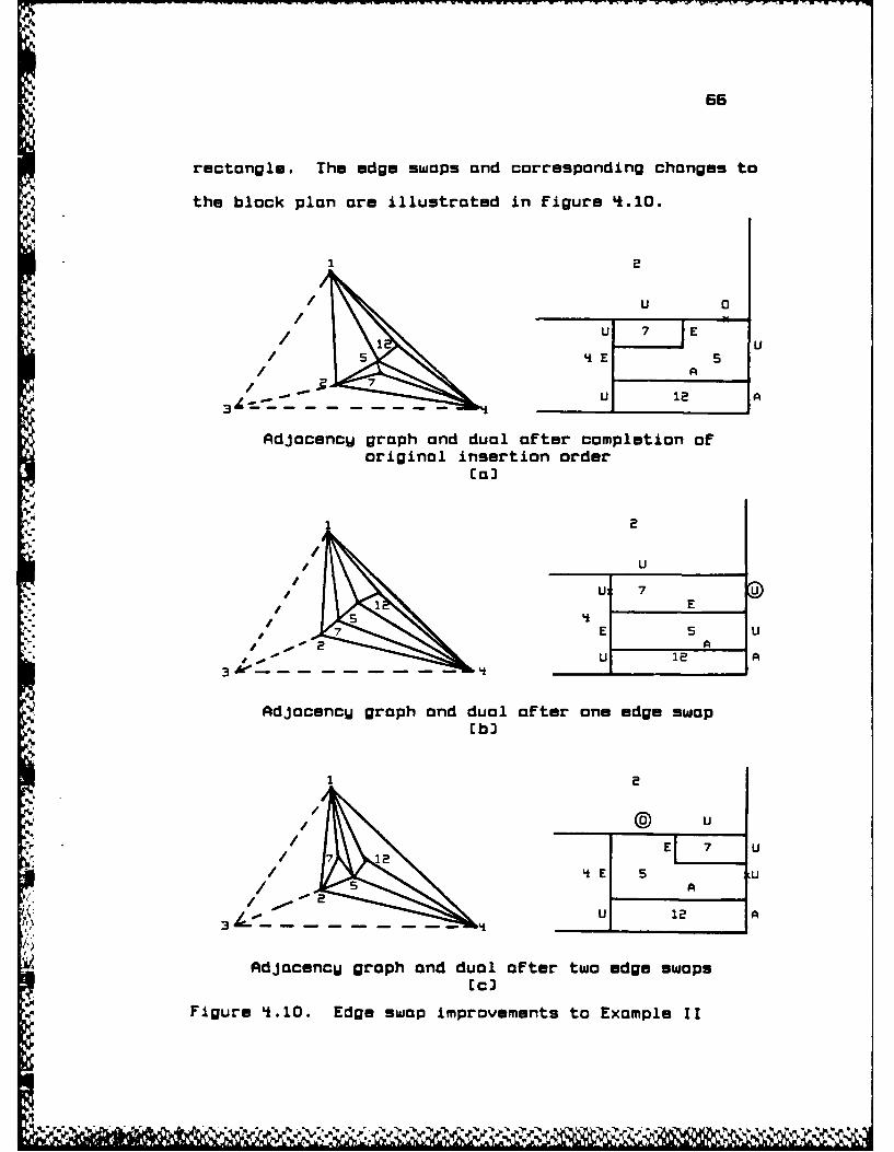
65
rectangle. The edge swaps and corresponding changes to
the block plan are illustrated in figure 4.10.
2
/U 0
U 7 E
/ A/ 7
U 12 A
Adjacency graph and dual after completion oforiginal insertion order
(aJ
2
U
./ U 7 E U
J# 7k El 5 U
J. - U1 12 A
AdJacencu graph and dual after one edge swap
1 2
@ u
/71 12 E U4 EE 5 U
55 A
U 12 AA)
,3 4
Adjacency graph and dual after two edge swaps
Figure 4.10. Edge swap improvements to Example II
N
i , 9 , , " , ,
" . . . " " " = , , " % " ", " " T - " " . " " 0 "

67
12
/0 U
/ 2E 5 E 7 U
/ i i
/ At/
Li 12 A3 4 1
AdjacencU graph and dual after three edge swaps[d3
Figure 4.1O--Cgntinued.
It should be noted that since there is no vertex in the
subgraph illustrated with degree three, there is no
possible wau to generate this graph using onlU the
Deltahedron method as the last vertex inserted must have
degree three. Additionally, the current Improved
Deltahedron would not consider this sequence of changes
since the first swap results in a lower score; therefore
a look ahead procedure would be required. It is
therefore proposed that everW permissible edge swap can
be characterized in the dual (and the block plan3 as
transforming a carve into a box or a box into a carve.
It is further proposed that since everU maximally planar
graph can be constructed from an initial tetrahedron bW a
series of vertex insertions and edge swaps, [Giffin,
19843 if the sequence is known it is possible to
construct the dual of all maximally planar adjacencU
graphs. The computer implementation of this procedure

has not Uet been done nor has the multiple step look
ahead implementation of the Improved Deltahedron method.
This is left for future research.
The final example is a real world problem and
illustrates the degeneracw that often occurs in some
larger actual problems. It also illustrates the outcome
of a problem that is too large to be solved bU the
current program. Consider the REL chart illustrated in
figure .11.
I
4
'p
'p

65
1 Exterior<
2 Loser 0 )-1075 0 O0
'3 Zyolo 0 0
16 trooms
7 Mochhe Shop [
- 1S2o E 0 0
i 21 0uin e12 Milloing 0 0 0 0
Fiur 64.1 Exmi 0I 0E 0h0 t
7~ Lathre 0 0 0 0 0U-2000, 0j 0> 0 <0 0
6 Prestsinmg 0I 0 0 0 3
-a 17 0 1nhn 0ho 0( 0 0 1
I9 Sheapgr e0 0iving0 U
1 0 Fusp tion ldin 0' i
11 Rles anne Wedn y
'V
2200 0 0 0 0 0 0 a 0
70
It is clear from an inspection of the REL chart that
facilities 2, 5, 11, and 16 have no rating other than 0
with respect to all other facilities. Therefore the
problem is degenerate because when choosing among'4. triangles for facilities 2, 5, 11, or 16, anU triangle is
as good as everU other. AdditionallU, facilities 3 and *
have an E onlU between themselves and an 0 with all
others as do 6 and 7. It follows that as long as 3 and k
are adjacent and 6 and 7 are adjacent, a block containing
facilities 2, 3, 4, 5, 6, 7, 11, and 16 could be placed
anuwhere in the graph and result in the same score as
-4 placing it anUwhere else. Because of this propertW,
there are literallU thousands of combinations that would
result in the same score but have different adjacencU
.4.. graphs. One approach to this dilemma might be to group
the B facilities into one large facilitU and thus reduce
the size of the problem bU more than a third. For the.
sake of demonstration however, the entire problem is run
as given. This illustrates the problem encountered bU
the current program when the AS matrix becomes too small
4. to add all of the required facilities within it. The
Deltahedron method runs without incident with the initial
tetrahedron being facilities 1-19-22-21 and the insertion
vertices and triangles are given in table 4.3. As with
* examples I and II, the complete output is contained in
the appendix.
-

71
.11
Table 4.3 Example III Vertices and Insertion Triangles------- --------------- Vortx ----------------- Ir--g-l- ---
8 <19 22 21>12 < 1 19 21>10 < 8 22 21>9 <18 21 8>13 < 1 22 21>18 <19 22 8>20 < 1 s 12>3 < 8 21 10>
< 8 21 3>6 < 10 3>7 < 6 10 3>
1 <20 1s 12>15 <18 22 8>2 < 10 5>5 < 8 6 2>
11 < 1 21 13>16 < 8 3 L>17 <15 22 8>
The resultant dual is given in figure L.12 and it should
be noted that there are onlW 19 Facilities shown.
Facilities 2, 5, and 16 were not able to be inserted
since there was no room at the new location for an
* additional facilitW. The program can be continued
- normallW from this point and output obtained, however the
block plan will not contain the facilities left out of
the dual (see figure 4.13).
:,,,,S,'a'=
as. , 'w. . ' . " . " ,' , " . " , , " , , . ' " . - " . " . " . - " ' . " % , % . " p

72
Figure 4.12. Example III Dual

73
19
., .---- --- J.5118
4 14?2
122
* 13
Figure 4.13. Example III Block Plan with 3 facilitiesnot included
To provide a complete block plan, the BREAK feature of
BASICA is used. Before continuing on to the construction
of the block plan from the dual, the program execution is
* stopped with the BREAK keU. When the program is halted
in this manner, the variables defined up to this point
remain in memorU. The values not present for the
complete construction of the block plan are the variables
I'7

74.
OPERS and PLIN for facilities 2, 5, and 16. An
inspection of the condensed AS matrix along with the
insertion values displaued on the screen Uield the
necessarU information to determine what the values would
have been had the program had the necessaru room. In
this case the following variables were set to the values
indicated below.
OPERSC1BJ-"BR1J" PLIN~lBJ-1'*OPERSC19)-"CJL" PLIN(19J-1BOPERS[21J-"CDR" PLINE213-13
After these values are set, execution is resumed and the
result is given in figure 4i.14i. It should be noted that
fo difrn random sedvalues, DLAANwill cmlt
this problem with no variable redefinition required.
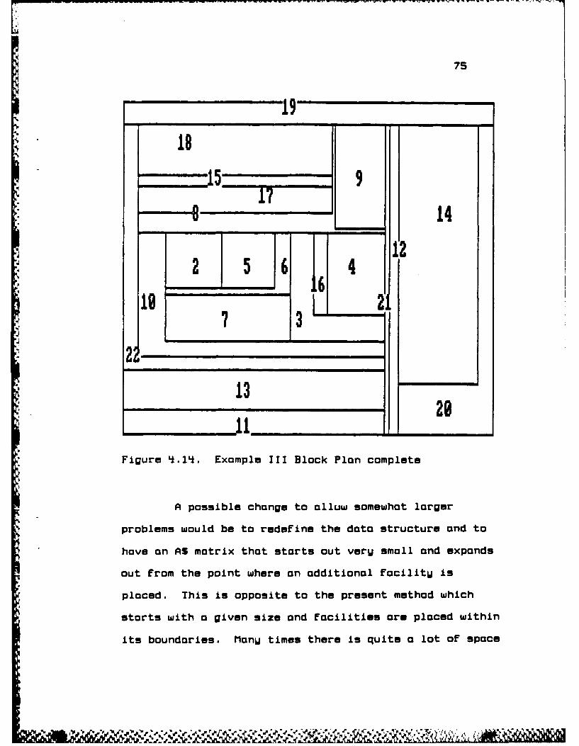
75
18
-"114
5 6
112___ 3 116
19 2 2
22" 29.
Figure 4.14. Example III Block Plan complete
A possible change to alluw somewhat larger
problems would be to redefine the data structure and to
have an AS matrix that starts out veru small and expands
out from the point where an additional facilitu is
placed. This is opposite to the present method which
starts with a given size and facilities ore placed within
its boundaries. ManU times there is quite a lot of space

76
remaining within the matrix; however, it is not where the
new FacilitU must be added.

CHAPTER 5
CONCLUSIONS
The method presented here has been shown to
construct a rectangular geometric dual for the class of
adjacency graphs developed using Deltahedron based
heuristics. It has further demonstrated how areas can be
incorporated to form a block plan. It should be
remembered however, that all of the methods described in
this thesis ore analytical in nature and as stated in
Francis and White [1974], "It should be realized that the
analytical approach yields a solution to the Mode, but
not necessarilu the Dgblm." For this reason, one
should be cautious when selecting a block plan produced
by any of the heuristics mentioned. Just because a
particular plan has a higher adjacency score does not
mean that it is a better plan. The moximallU planar
plans developed by DELTAPLAN sometimes hove long narrow L
or T shaped facilities which are most likely not very
useful if included as shown in the block plan. The
output of this as well as other methods is meant to be a
starting place and guide for further planning.
Alternatives that mao not previously have been considered
*might surface with a computer method such as DELTAPLAN.
77

78
As a starting point, the plan and REL chart maw be
consulted to see if perhaps one of the adjacencies in a
long narrow L or T shape is even worthwhile to have and
as such it maw become a candidate for deletion. If a
graph is not verw dense in highlW weighted edges, perhaps
a maximallW planar block plan contains more adjacencies
than are reallw necessarw. In this case some
adjacencies maW be deleted to form a more regular plan
and the adjacencW score maw not even be affected.
A veru important fact is that the dual is not
unique. There are manU waWs of arranging facilities with
verw slight changes to the rules of DELTAPLAN, that
preserve all of the adjacencies required. One change
might involve moving the initial inhibitors From the
right side of the wall between facilities 3 and 4 to the
left side. Another possibilitW would be to change the
placement of facilities 2, 3, and 4 within the dual
representation of the initial tetrahedron which would
lead to six different orientations of the initial Four
facilities. These ore either 2, 3, or L on the top and
the remaining two facilities placed either on the left
and right or the right and left. The point here is that
the rules developed for DELTAPLAN continue to work for
all of these orientations. If areas are not a factor or
if it con be determined that no new facilitw might affect
certain adjacencies after areas are added, changes to the
n t tt n ch e

79
inhibitors at a later stage can be invoked an result in
still further alternatives.
As mentioned earlier, extensions can be mode to
include edge swaps of the tUpe used in the Improved
Deltahedron. Further extensions include the abilitU to
develop the dual from anU maximallU planar adjacencU
graph once the series of vertex insertions and edge swaps
required to form the adjacencu graph From an initial
tetrahedron are known. As Uet it is not known how the
process of enforcing a deltahedron like insertion and
swapping procedure on an orbitrarU adjacencU graph should
be performed efficientlU. Another extension might be to
develop the block plan in parallel with the Super
Deltahedron method in order to have more accurate
estimates of the distance between centroids for
transportation cost estimates.
The implementation provided in this thesis should
form an important subroutine to the realization of all of
these extensions.

APPENDIX A
THE DELTAHEDRON HEURISTICPROGRAM LISTING
10 - - - - - - - - - - - - - - - - - - - - - - - - - - - - - - - -
2030 *The DELTAHEDRON HEURISTIC40 using column sums insertion order5060 by J. W. Giffin,70 with modifications by D. W. Keenan80 *March 1, 1586so- - - - - - - - - - - - - - - -- - - - - - - - - - - - - - - - -100110 DIM BEN [30,303,O0RDER C303,BENSUM C303,TRIANG EB',33,SOLUTION 130,303
*120 DIM OTHERS E303,DEG 1301,A E303,DEGCON [30),ROOTA E303130 DIM SPATH C30,30J,HP C33,H C303,VALIDC303,TRIANG5E303,
AREAC3O3 ,PS[30,30314i0 CLS150 RANDOMIZE160 DEFINT I-N170 INPUT "You will need to input the filename for the data you want to
Use. Would you like a list of files an the diskCY/NJ" ;ANSS
180 IF ANSS-"Y" OR ANSS-"w" THEN FILES190 INPUT"Enter anu Filename with .DAT For an extension"; FILENAMES200 IF RIGHTSEFILENAMES,'k3<".DAT" THEN FILENAMES-FILENAMES+".DAT"210 PRINT220 INPUT"If uou need an X value other than -1024i enter it at the prompt,if not press return." ;XLJALS230 IF XIJALS-"" THEN XVAL--l02* ELSE XIJAL-LALCXUALS]24t0 -- - - - - - - - - - - - - - - - - - - - - - - - - - - - - - - - -250 'Read data from data file and initialize NxN score matrix260 -- - - - - - - - - - - - - - - - - - - - - - - - - - - - - - - - -270 OPEN "I",#l.FILENAMES280 INPUT *1, IN250 PRINT "NUMBER OF FACILITIES:,"N300 FLAG -0310 K-7320 FOR I-1 TOIN330 PRINT USING "##";I;:PRINT":340O PRINT TABCK)350 PRINT USING "##";I ;:PRINT360 FOR J-I.1 TO IN
so

LB1
370 INPUT #1, PSEI,J]380 PRINT PSI,J] " ";390 IF PSIJ]-"U" THEN BEN [I,J]-O BEN CJ,l)-O :GOTO
450
'00 IF PSCIJ]-"O" THEN BEN CIJ-1 BEN EJ,13-1 :GOTO450
'10 IF PSCIJ]-"I" THEN BEN CI,J]-i BEN [J,I]- :GOTO50
420 IF PSIJ]-"E" THEN BEN (IJI-16 BEN [J,I]-16 :GOTO45S0
4i30 IF PS[IJ]-"A" THEN BEN [IJ]-6 BEN [J,1]-6 :SOTO50
440 IF PSI.J]-"X" THEN BEN [IJ]-XUAL BEN EJ,I]-XVAL:FLAG -1
4S0 NEXT J460 K-K+24i70 PRINT'i8O NEXT I'90 FOR 1-2 TO NSo INPUT #1, AREA[I]510 NEXT I520 CLOSE530 -5'0 'If an X is present, add a constont to all scores so theW550 'ore oll non-negative560 '-----------------------------570 IF FLAG -0 GOTO 630560 FOR I-i TO N590 FOR J-l TO N500 BEN [IJ]-BEN [I,JJ-XUAL610 NEXT J620 NEXT I630 FOR I-I TO N640 BEN I,13-0650 NEXT I660 GOSUB 1530670 .............650 'Initiolize total score and odd the score690 'For the initial tetrahedron700 .............710 TOTBEN -0720 FOR I-1 TO 4730 FOR J-I+1 TO 4740 TOTBEN -TOTBEN +BEN [ORDER CI,ORDER [J3]750 NEXT J760 NEXT I770 ----------780 'Determine best triangle for vertex insertion790 . -----------------------------800 FOR I-5 TO N810 MAX--1
I

820 X-ORDER EI]830 CK-1+INT(RNDOTRINO IB40 FOR K-CK TO TRINe850 SUM -0560 FOR J-1 TO 3870 SUM -SUM -BEN EX ,TRIANG CK,J)550 NEXT J590 IF SUM > MAX THEN MAX-SUM : MAXTRI -K50 NEXT K910 FOR K-1 TO CK-1920 SUM -0
.9. 930 FOR J-1 TO 3940 SUM -SUM +BEN CX TRIANG CK,JJ)950 NEXT J5ll 960 IF SUM ) MAX THEN MAX-SUM : MAXTRI -K970 NEXT K580 .-----------------------------990 'Print vertex and triangle it is inserted into1000 .-----------------------------1010 PRINT "INSERTING VERTEX ";X ; IN TRIANGLE ".1020 FOR K- 1 TO I1030 IF TRIANG CMAXTRI,1) - ORDER CK] THEN ELMNT1-K: GOTO
10501040 NEXT K1050 PRINT TRIANG [AXTRI ,13;1060 FOR K- 1 TO I1070 IF TRIANG [MAXTRI,2) - ORDER [K] THEN ELMNT2-K: GOTO
10901050 NEXT K1090 PRINT TRIANG (MAXTRI ,23;1100 FOR K- 1 TO I1110 IF TRIANG CMAXTRI,3] - ORDER [K) THEN ELMNT3-K: GOTO
11301120 NEXT K1130 PRINT TRIANG (MAXTRI ,3);
, 1140 '---- . . . . . . . . . . . . . . . . . . . . . . .1150 'Create character sting elements used as input for DELTAPLAN1160 ...........1170 IF ELMNT1IO THEN ELMNT1S-"0"+RIGHTSSTRSCELMNT1),1 ELSE
ELMNT1S-RIGHTSCSTRSCELMNT1],2)1180 IF ELMNTE<10 THEN ELMNT2S-"0"+RIGHTSCSTRSCELMNT2],1J ELSE
ELMNT2S-RIGHTSCSTRS(ELMNTE),2]1190 IF ELMNT3<10 THEN ELMNT3S-"0".RIGHTSCSTRSCELMNT3),1) ELSE
ELMNT3S-RIGHTSESTRSCELMNT33,2)1200 TRIANGS[IC-ELMNT1S ELMNT2S ELMNT3S1210 PRINT TRIANG3CI)1220 PRINT1230 GOSUB 21301240 TOTBEN -TOTBEN *MAX1250 NEXT I1260 IF FLAG-1 THEN TOTBEN-TOTBEN * XUAL&E3*N-6)
V

J 1 83
1270 PRINT1280 PRINT "TOTAL DELTAHEDRON ADJACENCY SCORE IS" TOTBEN1290 PRINT1300 GOSUB 22B01310 . -------------------------1320 'Write output to data file1330 ------------------------------1340 OPEN "O",#1,"DATA1"1350 WRITE #1,N1360 FOR 1-1 TO N1370 WRITE #1,ORDER(IJ1380 NEXT I1390 FOR I-5 TO N1400 WRITE #1,TRIANGS[I]1410 NEXT 11420 FOR 1-2 TO N1430 WRITE #1,AREACORDERCIJJ1440 NEXT I
S150 CLOSE1460 INPUT "WOULD YOU LIKE A LAYOUT DONE FROM THIS DATA CY/N]";ANSS1470 IF ANSS-"N" OR ANSS-"n" GOTO 1SO1480 CHAIN "DELTAPLN"10so END1500 -------------------------1510 'Print NxN score matrix1520 ..............1530 'FOR 1-1 TO N150 ' FOR J-1 TO N1550 ' PRINT BEN [I,J];1560 ' NEXT J1570 PRINT1560 'NEXT I1590 PRINT1600 '---- --------- ------------1610 'Calculate column sums1620 .-------------------------1630 FOR J-1 TO N160 SUM -01650 FOR I-1 TO N1660 IF I<>J THEN SUM -SUM +BEN CIJ)1670 NEXT I1680 BENSUM CJ]-SUM1690 NEXT J1700 FOR I-1 TO N1710 VALID CI]-11720 NEXT I1730 FOR 1- 1 TO N1740 ORDER (I]-I1750 NEXT I
* V

Bli
1760 -
1770 Sort vertices according to column sums1780 ' Bubblesort orroW order according to BENSUM1790 ....
1800 FLIPS -11810 WHILE FLIPS -11820 FLIPS -01B30 FOR 1-2 TO N-1
1840 IF BENSUM CORDER I1)) < BENSUM CORDER I+1)) THEN SWAPORDER [I),ORDER [I+1i :FLIPS -1
1850 NEXT I1860 WEND1870 '-------------------------1880 'Print deltahedron insertion order1890 '---------------------------
1900 PRINT1910 PRINT "DELTAHEDRON INSERTION ORDER"1920 PRINT1930 FOR I-1 TO N1950 PRINT ORDER CI3;1950 NEXT I1960 PRINT:PRINT1970 '-- - - - - - - - - - - - - - - - - - -
1980 'Initialize triangles and incidence values for the
1990 'initial tetrahedron2000 '-------------------------
2010 FOR I-1 TO 42020 X -ORDER CI)2030 FOR J-1 TO 42040 Y -ORDER (J]2050 IF J<I THEN TRIANG [I,J]-Y ELSE IF J>I THEN TRIANG
(I,J-1]-Y ; SOLUTION CX,Y]-:SOLUTION [Y,X]-12060 NEXT J2070 NEXT I2080 TRINO -42090 RETURN2100 .-------------------------2110 '<<< Relabel deleted triangle and add two more )>>
2120 .-------------------------2130 FOR J-1 TO 32140 SOLUTION CX ,TRIANG CMAXTRI,J])-l2150 SOLUTION [TRIANG CMAXTRI,J],X ]-1
2160 NEXT J2170 TRINO -TRINO +12180 TRIANG [TRINO ,1]-TRIANG CMAXTRI,1]
2190 TRIANG (TRINO ,23-TRIANG [MAXTRI,2]
" 2200 TRIANG [TRINO 33-X2210 TRINO -TRINO +12220 TRIANG CTRINO ,1]-TRIANG [MAXTRI,12230 TRIANG [TRINO ,2]-TRIANG C[AXTRI,3]2240 TRIANG [TRINO ,31-X
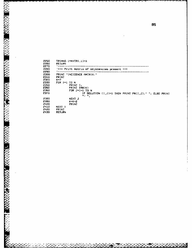
as
, ,2250 TRIANG [MAXTRI,l]-X,.60 RETURN
•2270 --- -- --- -- --- -- --- -- --- -- --- -- --- -- --- --, 2280 '<<< Print matrix oF adjacencies present >>>
2 29 0 -- - -- - - -- - - -- - -- - - -- - - -- - -- - - -- - -.. 2300 PRINT "INCIDENCE MATRIX:"
2310 PRINT
2320 K-72330 FOR 1-1 TO N234 0 PRINT I ;2350 PRINT TAB[KI
.2360 FOR J-I 1 TO N• ,2370 IF SOLUTION [I,J]-I THEN PRINT P$[I,J];".. ELSE PRINT
2380 NEXT J2390 K-K 2
.2400 PRINT. '.2410 NEXT I-,'". 2'20 PRINT
2230 RETURN
% 2
220 <CPitmti rojcnispeet
AD-i7i 339 BLOCK PLAN CONSTRUCTION FROM A DELTAI4EDROW BASED 2/2ADJACENCY GRAPH(U) AIR FORCE INST OF TECHWRIGHT-PATTERSON RFB ON4 D W KEENAN t986
SSFE FTC/R8-2TFG 22 M
EhhhhhhhhhhhhEi soSfl..l..fl.flflll

IlIJII.O I
L5-ll ,__io
I A.B
MICROCOPY RESOLUTION TEST CHART
NATIONAL BUREAU OF STANDARDS-1963-A
I--I---I- m .w:--. ... "..... -_ I" ...... .II... I- ... " ..... ""

APPENDIX B
DELTAPLANPROGRAM LISTING
2030 *DELTAPLAN
0 :A Procedure to Construct a Rectangular Geometric Dual and50 * a Block Plan from a Daltahedron Based AdjacencU Graph6070 bu David Wd. Keenanso M Iarch 1, 1986
100110 KEY OFF120 SCREEN 1130 WIDTH 80140O CLS
I60 '--CI.J) ARE THE INSERTION TRIANGLE COORDINATES270 '--LIl,Jl) ARE THE OPPOSITE CORNER COORDINATES OF THE NEW FACILITY1S0 '--L IS THE HORIZONTAL COORDINATE OF THE NEXT ADJACENCY TRIANGLE TO190 'THE LEFT2 00 * --R IS THE HORIZONTAL COORDINATE OF THE NEXT ADJACENCY TRIANGLE TO210 'THE RIGHT2 20 '--D IS THE VERTICAL COORDINATE OF THE NEXT ADJACENCY TRIANGLE BELOW230 '--U IS THE VERTICAL COORDINATE OF THE NEXT ADJACENCY TRIANGLE ABOVE21*0 '--.FLAGO-O INDICATES THE DIRECTION IS USABLE250 '---.FLAGO-1 INDICATES THE DIRECTION IS NOT USABLE260 '--..FLASl INDICATES A CORNER OR THE ABSENCE THEREOF -- 0-NO CORNER,270 1l-LOWER LEFT CORNER, 2-LOWER RIGHT CORNER, 3-UPPER RIGHT CORNER,280 "i-UPPER LEFT CORNER290 -------------------------------------------------
300 DIM ASC3S.661,RlS(£002,R2E£OOJ,R3t200),PLINESOI,PLINSESO).OPERSCSO],TRIANGLESCSO],AREA(5O) ,AREAINE5OJ,ORDERE5OI
310 PLACE - 3320 CT-1330 BLS-STRINGSC7S, 32)3410 '))INITIALIZE MATRIX350 GOSUB 10410360 ')> GET INPUT AND DETERMINE ITS COORDINATES370 FOR FAC-5 TO NUMFAC380 L-0390 R-0
6
11, 11 11

87
4*00 D-0'*10 U-04*20 1-04*30 J-0
440 IF FAC < 10 THEN FACS-"0"+RIGHTSCSTRSEFACJ.13 ELSEFACS-RISHTSCSTRSCFACI ,23
4*50 GOSUB S430 '>> CLEAR FIRST LINE4*60 PRINT "Inserting facilitu";ORDERCFAC];4*70 LOCATE 2,1'*80 PRINT BLS4*90 AREAINEFACJ-AREACFACI500o SORT THE INPUT TO INSURE PROPER CHARACTER SEQUENCE510 SORTAS-TRIANGLESEFACJ :GOSUB 5070 :TRIANGLES(FACJ-SORTAS520 FOR X-1 TO CT530 IF TRIANGLE5CFAC3-R1S(X3 THEN I-R2(X]:J-R3[XJ :R2(X]30
:R3CX]JO :SOTO 550S4*0 NEXT XS50 IF 1-0 THEN LOCATE 2,1 :PRINT "THIS TRIANGLE CAN'T BE FOUND
AS LISTED -- TRY AGAIN ":SOTO 880550 '>>> BEGIN SEARCH570 >>>~ SEARCH LEFT
* - 58 GOSUB 1870590 '>>> SEARCH RIGHTS00 GOSUB 2010510 '>>> SEARCH DOWN620 GOSUB 2150530 '>>> SEARCH UP64*0 GOSUB 2250650 >>> CHECK FOR CORNERS AND CARVE IF POSSIBLE660 IF LFLA51-1 AND LFLAGO-O AND UFLAGOO0 THEN GOSUB 24*30 :SOTO
820670 IF LFLAS1-* AND LFLAGO-0 AND DFLAGO0O THEN GOSUB 264*0 :SOTO
820680 IF RFLA61-E AND RFLASOO0 AND UFLAGOO0 THEN GOSUB 2850 :SOTO
820590 IF RFLA61-3 AND RFLAGO-O AND DFLAGO-O THEN GOSUB 3060 :GOTO
820700 IF DFLA01-1 AND DFLAGO-O AND RFLAGO-0 THEN GOSUB 3270 :GOTO
820710 IF DFLA61-2 AND DFLAGO-O AND LFLAGO-0 THEN GOSUB 34*80 :SOTO
820720 IF UFLA01-3 AND UFLAGO-0 AND LFLAGO-O THEN GOSUB 3690 :SOTO
820730 IF UFLAG1-* AND UFLAGO-O AND RFLAGO-O THEN GOSUB 3900 :SOTO
82074*0 '>>> CHECK FOR INTERSECTIONS AND BOX IF POSSIBLE750 IF LFLAI3O-0 AND DFLAGO-O THEN GOSUB '*110 :SOTO 820760 IF LFLASO-O AND UFLAGOO0 THEN GOSUB 4*350 :SOTO 820770 IF RFLAGO-0 AND DFLAGO-0 THEN SOSUB '*590 :SOTO 820780 IF RFLAGO-O AND UFLAGOO0 THEN GOSUB '*830 :SOTO 820790 LOCATE E.1

Boo PRINT "This triangle cannot be inserted here, tru anotherlocation"
810 SOTO 880820 'CONTINUE830 LOCATE PLACE,SO84*0 PLINCFACJ-UALCPLINSCFAC3J850 PRINT ORDERCFACJ;AREACFAC3;" ";DPERSCFAC3;" ";TRIANGLESEFACJ;"
";PLINCFAC3850 IF PLACE >- 23 THEN PLACE - 1* ELSE PLACE - PLACE +1870 LINE CJ*1*.28, 1*+50J-EJl10+28. Il1*4'0J, .B980 NEXT FAC890 'FOR U-1 TO CTS00o PRINT RlS(U3;R2tUJ;R3[UJ910 'NEXT U920 'PRINT CT930 GOSUD 54*30 '>> CLEAR FIRST LINE9'i0 INPUT "Would uou like a loUout copu printed (Y/N]";ANSS950 IF ANSS - "Y" OR ANSS - "u" THEN GOISUB 1770960 6051.1 54*30 "))> CLEAR FIRST LINE970 INPUT "Would Uou like an insertion order copU printed [Y/N3";ANSS90 IF ANSI - "Y" OR ANSI - "U" THEN GOSUB 5370990 GOSUB 54*30 ')> CLEAR FIRST LINE1000 INPUT "Would Uou like to see the IaUout with areas EY/NJ";ANSS1010 IF AN5I-"Y" OR ANSS-"w" THEN GOSUD 51*801020 CHAIN "DELTASUV'1030 END'----------------------------------------------------------------104*0 '>), INITIALIZE MiATRIX1050 OPEN "I",I1."DATAI-1050 INPUT P1,NUIIFAC1070 FOR 1-1 TO NUilFAC1060 INPUT 01,OROEREII1050 NEXT I1100 FOR I-5 TO NUIIFAC1110 INPUT #1,TRIANGLESCIJ1120 NEXT 11130 FOR 1-2 TO NUIIFAC114*0 INPUT *1,AREAC131150 NEXT I1160 CLOSE1170 LOCATE 10,51180 PRINT "Please wait a few moments while things are being
initialized...."1190 FOR J-0 TO 661200 ASCOJ]-"01"1210 ASC,J3-"-"1220 AS[3,JJ]-"1230 AS(31*,J)-"-"121*0 ASE3,JJ-"01"1250 NEXT J1260 FOR 1-1 TO 34*1270 ASII03-"01"
% ~,'I /Zb' r

55
1280 ASEI.*33-"-"
1300 ASEI,53-"-*1310 ASCI,553-"Ol"1320 NEXT 11330 FOR J-2 TO 6'i134t0 ASE2,J]-"02"1350 NEXT J1350 FOR 1-4 TO 331370 FOR J1-2 TO 'i21380 ASEI*Jll"03*1350 NEXT J1140O0 FOR J2-44 TO 641'i10 AU(I,32J-"04t1'*20 NEXT J214i30 NEXT 11'440 ASE1,13-"000102"1'i50 ASEl ,65J-"000102"11*50 ASE3,1J-"010203-1470 AS[3,k33-"02030P'11*80 ASE3,6SJ-01004*1'*90 ASC3i, 13-"AAO103-1500 ASC31*,'3J-"01030*"1510 AS34'6S)-38010i"1520 ASC3,44It-"000000"1530 ASE3'*,443*-"000000"I5't0 CLS1550 LOCATE PLACE,S01560 PRINT ORDERC23;":;AREAC2J;RER3;":";AREA3;ORDER'i);":";AREA1*1570 PLACE-PLACE+11580 LINE (32,5'*2-E280,1863,,B1550 LINE c32,623-c200,1e6J,,B1500 LINE [200,523-C288,186J.,,1510 RlSC 1J-"010203"1620 R2(13-31630 R3C13-115140 RlS(23-"020304"1550 R2(23-31560 R3123-431670 R15133-"010204*"1680 R2EC3-31650 R3C33J6S
* 1700 R1SC1*3-"01030t"1710 REC'43-34*
1730 AREAINC2]-AREA(23174*0 AREAINC31-AREA(3I1750 AREAINC't-AREA'*I1750 RETURN1770 <<<(( PRINT AS MIATRIX1780 FOR J-65 TO 0 STEP -1
~-~x.VCZ

so
1750 FOR 1-0 TO 351600 *PRINT ASCI,JJ1510 IF LENCASCI,J33-5 AND ASCI,J3()"000000" THEN AAS-"-"
ELSE AAS-RIGHTSCAS(I,JJ.231520 IF AAS-"-" THEN LPRINT "-;ELSE LPRINT USING
"*" ;ORDERCUALCAAS33;1630 NEXT Ile84O LPRINT1650 NEXT J1560 RETURN1570 )>> <<< SEARCH LEFT1550 LFLAGO-01590 LFLA51-01900 LFLA52-01510 L-J1920 L-L-11930 IF L(I. THEN LFLASO-1: SOTO 2000194*0 AUALS-LEFTSCASCI 1L3,131950 IF AVALS-"-' THEN SOTO 19201560 IF AIJALS-"A' THEN LFLA01-11570 IF AUALS-"D" THEN LFLAG11*1950 IF ASCI,L]-"000000" THEN LFLA62-11990 IF L-J-1 OR L-J-2 THEN LFLAGO-12000 RETURN2010 '>>> (<< SEARCH RIGHT2020 RFLAGO-02030 RFLAG1-020410 RFLA52-02050 R-J2050 R-R.12070 IF R>65 THEN RFLAGO-1: SOTO 214*02080 AVALS-LEFTSEASCI,RJ,1J8090 IF AVALS-"-" THEN SOTO 20502100 IF AUALS-"B' THEN RFLA81-22110 IF AVALS-"C" THEN RFLASI-32120 IF ASCI,RJ-"000000" THEN RFLA62-12130 IF R-J+1 OR R-J+2 THEN RFLASO-1214*0 RETURN2150 '>>> ((< SEARCH DOWN2160 DFLAGO-02170 DFLA81-02180 DFLA62-02150 D-12200 D-0+12210 IF D>34* THEN IFLAGO-1: SOTO 22502220 AVAL-LEFTSASDJJ,132230 IF AUALS-"-" THEN SOTO 2200224*0 IF AVALS-"A" THEN DFLAG1-1250 IF AVALS-"B" THEN DFLAS1-22260 IF ASCD,J]-"000000" THEN OFLA02-12270 IF 01.1l OR D-1+2 THEN OFLAGO-1

91
22B0 RETURN2250 *>>> <<< SEARCH UP2300 UFLAL3O-O2310 UFLA61-02320 UFLA62-02330 U-12340 U-U-12350 IF Uci THEN UFLAGO-1: SOTO 242802360 AtALS-LEFTSCASCUJ3.132370 IF AIJALS-"-" THEN SOT0 23402390 IF A#ALS-"C" THEN UFLA51-32390 IF AVALS-"DO THEN UFLA61-424I00 IF ASCU,JJ-"OO00000 THEN UFLA62-12410O IF U-I-1 OR U-1-2 THEN UFLASO-124280 RETURN2430 '>),> <<< CARVE LEFT-UP2440 IF UFLA62-1 THEN Il-U~l ELSE I1-I-CINTCABSE J3/2132450 JI-L24650 LS-ASr1'1,Jl-l22470 US-ASCIl1,Jl+1324BO RS-ASCll.1,J~1J24950 SORTAS-LS+US*FACS : OSUB 5070
AlE II,Jl1JSORTAS:CT-CT.1:RlSECTI-SORTAS:R2CCTJIl: R3CCT3-JI8500 SORTAS-RS+US+FACS : OSUB 5070:
ASEII,J-SORTAS:CI-TT+:RStCI)SRAS:REECT)mI1:R3ECT)2J2510 SORTAS-Ls+RS*FAC9 GOSUB 5070:
AlE I, JJSORTAS: CTmCT+1:RlSCCT)-SORTAS: RECTI R3[CT]-J8580 50RTAS-"AA"4LU+FACS : 05UB 5070 Air I,SJ-SORTAS2530 ASC11-1,J)J"000000"2540 ASC11-1,Jilm"000000"2550 OPERSCFACJ-"CLU"8560 PLINSEFAC)-US2570 FOR J2-J1+1 TO J-18580 AiEIlJ23--"2550 FOR 12-11+1 TO 1-12600 ASr 12,j8j-FACS8610 NEXT 122680 NEXT J28630 RETURN2640 '>>> << CARVE LEFT-DOWN2650 IF DFLAG2-1 THEN 11-0-1 ELSE I1-I+EINTrA~sCI-D3/828660 .1L1£670 LS-AUC1l-1J.1-132580 DS-ASEI1'1.Jl*1J8650 RS-ASEIl-1,Je132700 SORTAS-LS4OS.FACS : OSUB 5070
AlE II,Jl1JSORTAS:CT-CT+1:RlSCCTI-SORTAS:REECT~I1I:R3ECT)-Jl8710 SORTAS-RS+DS*FACS :BOSUB 5070
ASC11,J-SRTAS:CT-CT+1:RISCCT3-S0RTAS:R2(CTJI11:R3(CTI-J8780 SORTA5-LS+RS*FACS : GOSUB 5070:
Alt I,J]-SORTAS:CT-CTe1:RlSCCTJ-SORTAS:R8CCTJ-I:R3ECTI-J

2730 5ORTAS-"ID"+L$+FACS :GOSUB 5070 ASEI,JlJ-SORTAS274t0 ASCII1+1J3)"000000"2750 ASCIl~l,JlJ-"OO0OO002750 0PERSEFACJ-"CLD"e770 PLINSCFAC3-DS2780 FOR J2-jle1 TO J-12790 AscI1,J2]-"-"2800 FOR 12-1+1 TO 11-1.2810 ASCI2,J2]-FACS2820 NEXT 122830 NEXT J22840 RETURN2850 '>, ("t CARVE RIGHT-UP2860 IF UFLA62-1 THEN Il-U+l ELSE 11-I-CINTCABSCI-UJ/2332870 J1-R2880 LS-ASC1.1,J-1J28350 US-ASCI1l-l2500 RS-ASCI1.1.Jl+lJ2510 5ORTAS-RS+US+FACS :GOSUB 5070
ASC1.J1]-SORTAS:CT-CT1:RlSCCT3SORTAS:R2CT-11:R3ECTJ-JI2920 5ORTASL.US.FACS :GOSUB 5070:
ASCII,JI-SORTAS:CT-CT+1:RlSECT3-SORTAS:R2[CT2-11:R3CCTI-J2930 SORTAS-LS4RS.FACS :GOSUD 5070:
AS(I,J3-SORTAS:CT-CT1:RlSCCTISORTA:R2CCT-I:R3(CT)-J2940 SORTAS-"BB"+RS+FACS :GOSUB 5070 ASCIJl3-SORTASa550 ASEII-1 ,3"000000"2550 ASCIl-1,J1J-"000000"2570 OPERSCFAC3-"CRU"2580 PLINSEFACJ-US2930 FOR J2-J'1 TO Jl-l30,30 ASCI1,J23-"-"3010 FOR 12-11+1 TO I-i3020 AS[12,J23-FACS3030 NEXT 1230'*0 NEXT J23050 RETURN3060 '>) 4t< CARVE RIGHT-DOWN3070 IF DFLAG2-1 THEN 11-0-1 ELSE 11-I'CINTCABSCI-DJ/2333080 JI-R3050 LS-ASCII-1,J-133100 DS-ASCI1+1.Jl-ll3110 RS-ASCI1-1,Jl133120 SORTAS-RS+D5+FACS :GOSUB 5070
ASEII,J13-SRAS:CT-CT1:RlStCT)-SORTAS:R2ECJ-11:R3ECT2-JI3130 SORTAS-LU.DS+FACS :GOSUB 5070:
AStI1,J3-SORTAS:CT-CT+1:Rl5CCTI-SORTAS:R2CCTI11:R3CCTIJ314i0 SORTAS-LS+RS+FACS :GOSUS 5070
ABC I,JJ-S0RTAS:CT-CT.1:R1SCCTI-SORTAS:R2ECTJ-I:R3ECTJ-J3150 SORTAS-"CC"+RS.FACS :GOSUB 5070 :ABC I,J13-SORTAS3260 ASCI1.1,J3-'O0000"3170 ASC11,J1I-"O00000"

93
3180 OPERSCFAC)-'CRD"3190 PLINSCFACJ-DS3200 FOR J2-J+l TO 31-1
3220 FOR 12-1+1 TO 11-13230 ASCIE,J23-FAC53240 NEXT 123250 NEXT J23250 RETURN3270 '>>> <<< CARVE DOWN-RIGHT3280 Il-U3290 IF RFLAGE-1 THEN Jl-R-1 ELSE Jl-J+CINTEABSCJ-R3/2333300 US-ASCI-1,Jl-12
*3310 RS-ASC11-1,Jl+133320 US-AS(I1+1,J1-123330 SORTAS-RS+DS+FACS :GOSUB 5070
ASEI1,JlJ-SORTAS:CT-CT+:RSCTJ-SORTAS:R2CCTI11:R3CCTJ1334*0 SORTAS-"AA"+DS+FACS :GOSUB 5070 :AlE I1.J3-SORTAS33S0 SORTAS-US+DS+FACS :GOSUB 5070:
ASEI,J]JSORTAS:CT-CT+1:Rl5CCTJ.'SORTAS:R2CT-I:R3ECT-J*3360 SORTAS-RS+US+FACS :GOSUB 5070:
AlL I,JlJ'SORTAS:CT-CT+:RSCT]-SORTAS:R2[CT3-I:R3CCT3J13370 ASCI,Jl~lJ-"OOOOOO"33B0 Al I1, Jl1*1 J OO000"3390 OPERSCFACIJ"CDR"34*00 PLINSCFACI-RS34I10 FOR 12-1+1 TO 11-13420 ASC12,Jl3)"-"34*30 FOR J2-J.1 TO J1-13440j ASE12,J2]-FACS34SO NEXT J?34E60 NEXT 123470 RETURN348B0 '>>> <<< CARVE DOWN-LEFT34i90 11-03500 IF LFLA62-1 THEN Jl-Lel ELSE Jl-J-CINTEABSLJ-Ll/2333510 US-ASEI-1,Jl+1J3520 LS-AS[Il-1,Jl-lJ3530 Ul-ASCI1*1,Jl~1J3S4*0 SORTAS-LS+DS+FACS :GOSUB 5070
ASC11,J1)-SORTAS:CT-CT+1:RSCTJ5SORTAS:R2CT)11:R3[CTIJ13550 SORTAI-"BB"+DI.FACS GOSUB 5070 :AS[I1,J]-SORTAS3550 SORTAS-US+DS+FACS GOSUB 5070:
ASCI,J-SORTAS:CT-CT+1:RlCT)-SORTAS:R2CCTIIR3ECT)3J$93570 S0RTAS-LS+US+FACS GOSUB 5070:
AS(I,JlJ-SORTAS:CT-CT+1:RICCT3SORTAS:R2CTJ-I:R3(CTIJ13580 ASCI,Jl1l-"OO0000"3590 AlCI1,Jl-13m'000000"3600 OPERIE FACI-"CDL"3510 PLINS(FAC2-LS3520 FOR 12-1+1 TO 1l-1

3630 A5(I2,Jl3-"-"36'*0 FOR J2-Jl+i TO J-13650 ASElE,J23-FACS3650 NEXT J23570 NEXT 123550 RETURN3550 ')) <<< CARVE UP-LEFT3700 Il1U3710 IF LFLA62-1 THEN Jl-L+l ELSE Jl-J-CINTCABS(J-LJ/2JJ3720 US-ASCIl-1,Jl+l)3730 LS-ASEI1*1,Jl-lJ37'*0 DS-ASCI.1,Jl41J3750 SORTAS-LS+US+FACS :GOSUB 5070
ASEI1,JlJ-S0RTA5:CT-CT+1:RlSECTJ-SORTAS:R2CCTJ-11:R3CCT]-JI3760 SORTAS-"CC.+US+FACS :GOSLIB 5070 ;AS[11,J]-SORTAS3770 SORTAS-US.D5+FACS GOSUB 5070:
Alt I,JJ-SDRTAS:CT-CT.1:RlStCTJ-S0RTAS:R2tCT2-I:R3ECTJ3700 SORTAS-LS+DS+FACS : GOSUB 5070:
ASEIJ1)-SORTAS:CT-CT+1:RISECT)-SORTAS:R2ECT2I :R3ECT)-Jl3750 ASCI,Jl-ll-000000O"3800 AS[11,J1-13-"000000"3810 OPERSEFAC3-"CUL"3820 PLINSCFAC3-LS3530 FOR 12-11+1 TO I-13840 ASE12,Jll-"-"3550 FOR J2-Jl+l TO J-13850 ASC12,J23-FACS3B70 NEXT J23950 NEXT 123850 RETURN3500 '>>> <<< CARVE UP-RIGHT3510 I1-U3920 IF RFLAG2-1 THEN Jl-R-1 ELSE Jl-J+EINTCABSCJ-R3/2J23930 US-ASC11-1,Jl-lJ3540 RS-ASEI1+1,Jl.1J3550 DS-ASCI.1,Jl-lJ3550 SORTAS-RS+US+FACS GOSUB 5070
Alt Ii. J1JSORTAS:CT-CT+1: RlSECT)JSORTAS R2CCTI11:R3[CTIJ13570 SORTAS-"DO"*US+FACS : OSUBS5070 :Alt 11,J]J5ORTAS3950 SORTAS-US+DS+FACS :GOSUB 5070
ASCI ,J]SORTAS:CT-CT+1:R1UCCTJ-SORTAS:R2CCTI:R3CCT-J3550 SORTAS-RS+DSeFACS : OSUB 5070:
ASCI.Jl1J5ORTAS:CT-CT+1:RlSCCTJ-SDRTAS:R2[CTJ-I:R3ECT3J14*000 AltI .J1.1J"000000"'4*010 ASCI1,Jl1*1J"O00000"4*020 OPERICFACIJ"CUR"4*030 PLINSCFACJ-RS4040 FOR 12-11+1 TO 1-1'*050 ASC12,Jl3-"-"4*060 FOR J2-J.1 TO il-iL1070 ASE12,J23-FACS

55
'*080 NEXT 124*050 NEXT 124*100 RETURN'*110 '>>> <<< BOX LEFT-DOWN'*120 IF DFLAE32-1 THEN Il-U-1 ELSE Il-I+CINTCABStI-03/2JJ'*130 IF LFLA62-1 THEN Jl1L+l ELSE Jl-J-CINTEABSEJ-L]/233
'*150 US-AS(1-1,Jl+lJ4*160 RS-ASCI+1,J+134*170 SORTAS-1'AA"+LS+FACS : OSUB 5070 :AS111,J13-SORTAS4180o SORTAS-RS+LS+FACS : G05UB S070:
ASCti ,J]-ORTAS:CT-CT+1 :R1SCCT)-SDRTAS:R2CCTJ-I1:R3ECTJ-J4*190 SORTAS-US+RS+FACS : OSUB S070:
ASEI ,J3SORTAS:CT-CT+1:RlSECTJ-SORTAS:R2CCT3I :R3[CTJ4*200 SORTAS-US+LS+FACS :GOSUB S070:
ASCI,Jl)-SORTAS:CT-CT+1:RISECTJ-SORTAS:R2[CTJ-I:R3CCT-Jl4*210 ASC1.1,JJ-"OO0000"'*220 ASCI ,Jl-ll-"000000"4*230 OPERSCFAC3-"DLD"4*240 PLINSCFACJ-LS4*250 FOR 12-1+1 TO 11-14*260 ASCI2,Jl3~-"4*270 NEXT 12'*280 FOR J2-J1.1 TO J-1'*290 ASCI1,J2]-"-"'4300 FOR 12-1+1 TO Il-i4*310 ASE12,J23-FACS4*320 NEXT 12'*330 NEXT J24*340 RETURN4 '350 '>>> <<< BOX LEFT-UP'*360 IF UFLAG2-1 THEN Il-Wil ELSE I1-I-CINTCABSCl-Ul/211'*370 IF LFLA(32-1 THEN Jl1L+l ELSE Jl-J-EINTEABS(J-L)/2J34*380 LS-ASCI-1,Jl-1J4*350 DS-ASCI+l,Jl+lJ'*'*00 RS-ASEI-1,J'1344'10 SORTAS-"DD"+LS.FACS :GOSUB 5070 :ASCI1,J13-SORTAS44'20 5ORTAS-RS+LS+FACS : OSUB 5070:I
ASCI1,J2-SORTAS:CT-CT+1:RlSECT)-SORTAS:R2ECTI1I:R3ECTJ4*430 SORTA5-DS+RS+FACS : GOSUB 5070:
ASCI,JJ-SORTAS:CT-CT+1:RlSCCT)-SORTAS:R2(CTJ-I :R3CCT-J444*'0 SORTAS-DS+LS+FACS :GOSUB 5070:
ASCI,JlJ-SORTAS:CT-CT+1:RlSECT3-SORTAS:R2(CTJ-I:R3CCTJ-Jl44'50 ASCI1-1,J]-"000000"446*0 ASrI ,J1-lJ-"OO0000"44'70 OPERSCFAC3-"BLU"
'1'448*0 PLINSCFACJLS449*0 FOR 12-11.1 TO I-14*500 ASE12,Jl3-"-"4*510 NEXT 124S520 FOR J211l+l TO J-1

56
4*530 AS[ 11,J23-"-"45S40 FOR I2-Il~l TO 1-1'*550 ASC I2,J2J-FACS'*560 NEXT 12'*570 NEXT J2'*580 RETURN'*590 '>>> <<< BOX RIGHT-DOWN'*500 IF DFLA62-1 THEN 11-D-1 ELSE Il1I+CINTCABSEI-DI/2334*610 IF RFLAG2-1 THEN Jl1R-1 ELSE J1-J+tINTEABSEJ-RI/23)4*620 LS-ASrI.J-1J4*630 US-ASEI-1,Jl-134*640 RS-AStII.Jl+1346550 SORTAS-"BB"+RS+FACS :GOSUB 5070 :ASCI1,Jl)-SORTAS4*550 SORTAS-RS+LS+FACS : G05U5 5070:
~IV ASEI1,J]-SORTAS:CT-CT+e1:RSCTSORTAS:R2CT)-Il:R3(CT)-J4*670 SORTAS-US+LS+FACS :GOSUB 5070:
ASCI,JJ-SORTAS:CT-CT*1:RlSCCT3ISORTAS:R2CCTJ-I:R3[CT)-J'*5B0 SORTAS-US+RS.FACS :GOSUB 5070:
ASCI,Jl1J5ORTAS:CT-CT+1:RlSCCTJ-SORTAS:R2(CTJ-I:R3[CT)-JI'*700 ASCI1J1.13-"000000"
4*710 OPERSCFACJ-"BRO"'A4'720 PLINSCFACJ-RS
4*730 FOR 12-1+1 TO Il-i4*740 AS(12JlJ-"-"4*750 NEXT 12'*760 FOR J2-J~l TO 31-14*770 AS(11,J2J-"-"4*780 FOR I2-I~l TO Il-i4*790 ASC12,J23-FACS'*800 NEXT 12'*B10 NEXT J2'*B20 RETURN48e30 '>>> <<< BOX RIGHT-UP4*840 IF UFLAG2-1 THEN I1-U.1 ELSE 11-I-CINTCABSEI-U)/2))'*8S0 IF RFLA62-1 THEN J1-R-1 ELSE Jl-J+(INTEABS(J-R]/2J)'*850 LS-ASCI-1,J-1J4*870 O3-ASCI+1,Jl-1J'*880 RS-ASCI-1,J11J'*890 SORTAS-"CC"+RS.FACS : OSUB 5070 :AS(Il,JlJ-SDRTAS'*800 SORTAS-RS+LS+FACS :GOSUB 5070:I
ASCII,J3-SORTAS:CT-CT+:RSCT3SORTAS:R2T311:R3CT)-J'*510 SORTASODS+LS+FACS : OSUB 5070:
ASCI,JJ-SORTAS:CT-CT+1:RlSECTJ-SORTAS:R2CCTJ-1:R3CCT-J'*920 SORTAS-DS.RS+FACS :GOSUB 5070:
AlE I,Jl1JSORTAS:CT-CT*1:RlSECTJ-SORTAS:R2CCTJ-I:R3CCTIJ1'*530 AS[11-1,J)-"000000"494'0 AlE 1,31. )-"000000"4*950 OPERSCFAC3-"BRU"'*950 PLINSCFACJ-RS4S970 FOR 12-11+1 TO I-1
,. Y .

97
Li010 ASCI1,J2]-"-"
5020 FOR 12Il+l TO I-15030 ASC12,J21-FACS504i0 NEXT 12S050 NEXT J25060 RETURN5070 '>>> <<< SORT ROUTINESo50o 'SORTAS IS THE ELEMIENT TO BE PUT IN NUMERICAL ORDER5090 NlS-MIOSCSORTAS,1,235100 N2$-MIDSCSORTAS,3,235110 N3S-MIOSCSORTAS,5,235120 IF NlS-"AA" OR NlS-"BB" OR N15-"CC" OR NlS-"DD" 5010 52705130 NE1)LJAL(NlSJS140 N[23-UALEN2S]5150 N(33-JALCN3S3
-'5160 FOR X-1 TO 25170 FOR Y-X+l TO 35180 IF NIX] <- N(YJ GOTO 52205190 H-NCXJ5200 NCX3-NCY]5210 NCYJ-H5220 NEXT Y5230 NEXT X524*0 IF N1)10 THEN NlS-"O"+RIGHTSESTRSN1),11 ELSE
NlS-RIGHTSCSTRSCE1J) ,235250 GOTO 53305260 GOTO 53505270 N(2J-VALCN2S]5280 NC314JALCN3S)5230 IF NC23 <- NC33 5010 53305300 H-N12J5310 NCEI-NC325320 NE33-H5330 IF N123<10 THEN N2S-"O"+RIGHTS(STRSCc231,13 ELSE
N2S-RIGHTSCSTRSEN(2)) ,2)534i0 IF NC33<10 THEN N3S-"O"+RIGHTSCSTRSC33),11 ELSE
N3S-RIGHTSCSTRSCNE3)) ,235350 SORTAS-Nl$+N2S+N3S5360 RETURN5370 '>>> <<< PRINT INSERTION ORDER5380 LPRINT ORDER(2); .:.;AREAE2);ORDER3;":";AREA3;RERC*);":";AREA'i)
A5390 FOR 1-5 TO FAC-15400O LPRINT ORDEREI),AREACI2;" ";OPERSCI);' ";TRIANGLESCI);"
5410O NEXT I ;PINI
S4t20 RETURN54i30 '>>> <<< CLEAR FIRST LINE[ 5440j LOCATE 1,1
41A 1* ~ % *1

9B
51*50 PRINT BLS51*60 LOCATE 1,.15S470 RETURN51*80 '>>> <<< AREA CALCULATIONS51*90 DIM ULIC5OJ,ULJESOJURIE50J,URJC5OJ.LL1C50),LLJE5O),LRI[5OJ,LRJC5025500 CLS5510 FAC-FAC-15520 PLINE33-25530 PLINC1*2-3551*0 FOR I-FAC TO 2 STEP -15550 AREAINEPLINEI]3-AREAINCPLINCIJJ+AREAINCII5560 NEXT I5570 AREATOT-AREA INC 2)5580 ULIE22-0:ULJE23-O5590 URI(2J0O:URJC2Jl15600 LLIC2J-1:LLJC2]305510 LRIC23J1:LRJC2]J15520 DRW-25630 I3OSUB 8550564*0 CARVE-3 :1-25650 GOSUB 61105650 CARVE-* :1-35670 GOSUB 65905650 FOR 1-3 TO FAC5550 CARUEO05700 50XI.05710 50X2-05720 FOR 11-I TO FAC5730 IF PLINCI13-I AND LEFTSCOPERSEI1J,13-"C" THEN CARVE-11574*0 IF PLINCI1J-I AND LEFTSEOPERSCI11,1J-"B" THEN
B0XI1I:GOTO 577057S0 NEXT 115760 SOTO 55105770 FOR 12-11+1 TO FAC5750 IF PLINE103-1 AND LEFTSCOPERSEI2J,1J-"C" THEN CARUJE-125790 IF PLINC121-1 AND LEFTSCOPER$CI2J.13-"B" THEN
B0X21I2:SOTO 58105500 NEXT 125e10 'CONTINUE5820 IF AREACBOX2)JAREACSOX13 THEN SWAP B0X1,B0X25530 IF CARUJE-0 SOTO 50055B40 IF OPERSCCARUEJ-"CLU" OR OPERSCCARVE3-"CRU" THEN GOSUB
6110 :SOTI3 58505550 IF OPERSCCARVE3-"CLD" OR OPERSECARUE)-"CRD)" THEN GOSUB 6270
:SOTO 58505860 IF OPERSECARVE]-"COR" OR OPERSCCARUEJ-"CUR" THEN GOSUB 61*30
:11O1TO 58505570 IF OPERS(CARVEJ-"CDL" OR OPERSCCARLDEJ-"CUL" THEN GOSUB 6590W850 IF DOX1-0 O 0005590 BOX-DOXi5900 IF OPERSEBOX13-"BLD" THEN GOSUS 6750:61OTO 594*0

5910 IF OPERSCBOX13-"BLU" THEN GOSUB 6920:60TO 5940O5920 IF OPERSEBOX1J-"BRD" THEN GOSUB 7090:6OTO 5940O5930 IF OPERSEBOX1J-'BRU" THEN GOSUB 72605940O IF B0XE-0 G0T0 60605550 FLAGFIT-O5950 IF DPERSCBOX23J"BLD" THEN G05U5 7'*30:6OTO 60005570 IF OPERSCBOX23-"BLU" THEN GOSUB 7710:GOTO 600055190 IF OPERSCBOX23-"BRD" THEN GOSUD 7990:60T0 60005550 IF OPERSEB0X23-"BRU" THEN GOSUB 82705000 IF FLASF IT-1 S0T0 60506010 BOX-BOX26020 IF OPERSCBOX2J-"BLD" THEN GosuB 6750:6OTO 50606030 IF DPERSCDOX2J-"BLU" THEN GOSUB 6920:60T0 60606040O IF OPERSCB0X2)3"BRO" THEN GOSUB 7050:S0T0 50605050 IF OPERSCBOX2J-"BRU" THEN GOSUB 72606060 NEXT 15070 LOCATE 23,16080 INPUT "Would Uou like a list of coordinates printed CY/NY';ANSS5050 IF ANSS-"Y" OR ANSS-"u" THEN GOSUB 835805100 RETURN6110 *)>> << CLU OR CRU6120 DISTUP-AREAINCCAR'JEJ/AREAINEI)*ELLIEIJ-ULI[IJJ6130 LLICCARVEJ-LLICIJ6140O LRI(CAR'JEJ-LRICIJ6150 LLICII-LLICII-DISTUP6150 LRI(IJ-LRI(I)-DISTUP5170 ULICCARVEJ-LLICIJ6180 URICCARVEJ-LRICIJ5150 ULJECARUE3-ULJCIJ5200 URJCCARVEJ-URJC II6210 LLJECARVEI-LLJEII5220 LRJCCARUEJ-LRJ( I)5230 ORW-CARJE52Lt0 GOSUB 85505850 AREAINCI3-AREAINCIJ-AREAINCARI5260 RETURN6270 '),> <<< CLD OR CRD5280 DISTDWN-AREAINECARVEJ/AREAINCI20CLLIrIJ-ULICIJJ5290 ULICCARVEJ-ULICIJ6300 URIECARVEJ-URItIJ6310 ULI(IJ-ULICI4'DISTOWN6320 URIEIIJURICI2+DISTDWN5330 LLIECARVEI-ULICII534I0 LRIECARLJE3-URICIJ6350 ULJECARLJEJ-ULJC 136360 URJICARVEJ-URJ( 135370 LLJECARVEJ-LLJ( I)6380 LRJCCARUE)-LRJC I26390 DRW-CARUE5400O GOSUD 85506410 AREAINCIJ-AREAINEI3-AREAINrCARUE)

100
6420 RETURN6430 '>>> I<< CDR OR CUR644~0 DISTRT-AREAINCCARVE)/AREAINC1IOEURJEIJ-ULJCIJJ6450O ULJCCARtJEJULJC I)64650 LLJECARUEJ-LLJC 136LI70 ULJCIJ-ULJCI)+DI5TRT61*50 LLJCIJ-LLJC13+DISTRT64*90 URJCCARUE3-ULJC II
6500 LRJECARUE3-LLJC 135510 ULICCARUEI2ULICIJ6580 URICCARLJEJ-URIE136530 LLIECARUE3-LLICI3540 LRICCARVI-LRICIJ
* 6550 DRW-CARLIE6560 BOSUE 85505570 AREAINE I -AREAINC13 -AREAINCCARVE36580 RETURN5590 '>>> <<< CDL OR CUL6600 fISTLT-AREAINECARVE/AREAINIJOCURJCI3-ULJCI2J5610 URJ(CARUE3-URJ( I]6620 LRJCCARLJE3-LRJ(I36630 URJEIJ-URJCIJ-DISTLT551*0 LRJC13-LRJCI3-DISTLT5650 ULJ(CARUEJ-URJ(1I6660 LLJECARIEI-LRJC 135670 ULIECARLJEI-ULIC1365S0 URI(CARVEJ-URICIJ6590 LLICCARVEI-LLICIJ6700 LRICCARLJEJ-LRICIJ5710 DRW-CAR6JE6780 GOSUB 85506730 AREAINE I -AREAINC I -AREAINCCARVEI674*0 RETURN5750 '>>> t<< BLO6750 DISTLT-[AREAINEBOX3/AREAIN(IJJA.SOCURJIJULJEI)J5770 DISTDWN-CAREAINBD0XJ/AREAINCI3JA.5CELRICI)-URICIJ35780 URICBOXI-URICI36790 URJCBOXJ-URJC(U5800 URICI3-URI(13+DISTOWN6810 URJCIJ-URJCIJ-DISTLT6880 LLIEBOX3-UPICII6930 LLJCBDXI]URJCIJ68LI0 ULICBOXJ-ULICIJ6850 ULJCBOXJ-URJC135860 LRIEDOX3-URICIJ6870 LRJCBOXI-LRJC135880 DRW-BOX6890 GOSUB 85506900 AREAINE I -AREAINE1I3-AREAINEBOX)6910 RETURN6520 '>>> <<< BLU

101
6530 DI5TLT-CAREAIN(B0X3/AREAIN(I33A.S(CLRJ(I)-LLJEI)35940 DISTUP-CAREAINCBOX3/AREAINE1I33' .SOELRIC I -URIC 1336550 LRIESOX]-LRICII6550 LRJCDOX3-LRJ(I35570 LRIC13-LRIE13-DISTUP6580 LRJE13-LRJE13-DISILT6950 ULICBOX3-LRIEI37000 ULJCDX3-LRJ[137010 LLIEBOX3-LLIE137020 LLJCBOX3-LRJCII7030 URIEDOX3-LRIEI37040 URJEBOXI-URJE137050 I3RW-BOX7050 GOSUB 55507070 AREAINEI3-AREAlII3-AREAINEBOX37080 RETURN7090 '>)> <<4 BRD7100 DISTRT-CAREAINCB0X3/AREAIN[133'A.SOEURJCI3-ULJCI37110 DI5TDWN-EAREAINEBOX)/AREAINEI33A.5eCLLIC I -ULIEI))7120 ULIEBOX3-ULICI37130 ULJCBOXI-ULJCIJ7140O ULIEIJ-ULICIJ.OISTDWN7150 ULJCII-ULJCIJ.O!STRT7160 LRIEBOX3-ULICI37170 LRJCBOX3-ULJCI)71B0 URIEBOX3-URICIJ7190 URJCBOXJ-ULJC!37200 LLIEDOX3-ULICI37210 LLJEBOX3-LLJCI)7220 DRWa-BOX7230 GOSUB 8550724i0 AREAINEIJ-AREAINCII-AREAINCBOX)7250 RETURN7250 >)> <<< BRU7270 DISTRT-(AREAINEBDX3/AREAINCI33'.5*CLRJCI3-LLJcI3372150 DISITUP-CAREAIN(B0X3/AREAINEI33A.5SCLLIEIJ-ULIEI3)7290 LLICBOXI-LLICIJ7300 LLJEBOXI-LLJE137310 LLIE13-LLICII-DISTUP7320 LLJCI]-LLJCIJ.-DI5TRT7330 URICBOXI-LLIE13734i0 URJCB0XJ-LLJEI37350 LRIEBOX3-LRICIJ7360 LRJCBOX)-LLJCIJ7370 ULIEBOXI-LLICI373190 ULJCBOXJ-ULJCI37390 DRW-BOX74*00 GOSUB 855074t10 AREAINCI3-AREAINCI3-AREAINCBOX)74t20 RETURN74*30 '>>> <<< BLO CORRECTIONS

102
7440 IF OPERSCBOX13-"BLU" SOTO 7560 'IF NOT IT"S BRD74t50 LLJEI2-ULJCI374i60 ULICIJ-URI(12
"74j70 AREAINEIJ-CLRJCII-LLJE1J30ELLIEIJ-ULI(IJJ*AREATOT74980 IF AREAINEI2O.98<AREAINEB0X2] THEN DRW-BOX1:SOSUB B660:GOSUB 6700 ELSE
SOTO 770074950 LLJCII-ULJCIJ7500 URJCBGX13-ULJC137510 LL CHOX13-CAREAINCBOX1)/AREATOT/EURJDX1J-ULJ(BOX1333+ULICDOX137520 LRJCBOX13-URJEBOX137S30 LRIDX1)-LLIEBOX137S40 DRW3BOX17550 GOSUB 85507S60 LINE CINTCURJEBOX130't003+5O, INTCURICDOX13*1503+252 -
CINTCURJCU3*kOO+50, INT(URICI]lOS3+2S37570 SOTO 77007580 LRJEI]-URJEIJ7550 LLICIJ-LRICIJ7500 AREAINCI3-CLRJCI3-LLJCIJJ*ELLICI3-ULICI]3*AREATOT7510 IF AREAINCIJ'.90<AREAINCSOX23 THEN DRWSBOX1:SOSUB 8B50:SOSUB 874*0 ELSE
SOTO 77007520 LRIC13-LLIE13
N7630 URIEBOX13-LLIE137640 LLJCBOX1 ]--AREAINCBOX1 3/AREATOT/ELRICDOX1J-URIEDOX1)J J*LRJCBOXlI7650 ULTEBOX11-URIEBOX137660 ULJEBDXl]-LLJEBOX137670 DRW-BOX17680 GOSUD 85507690 LINE EINTCURJCB0X1J*'i002+50, INTCURIEBOX1J*1SOJ.253-
(INTEURJCIJ*'i003.60, INTEURICI31lS0)*2SJ7700 RETURN7710 ')>> <<< LU CORRECTIONS7720 IF OPERSCBOX13-DBRU" SOTO 7850 'IF NOT IT"S BLO7730 URJEI3-LRJCIJ77410 UUICI3-URICI37750 AREAIN(13I LRJC I -LUJC I JJCLLICIJ-ULICI3)*AREATOT7750 IF AREAINCI3*.S8(AREAINCBDX23 THEN DRW-BOX1:SOSUB 8850:5OSUB 8820 ELSE
SOTO 79807770 URI[13-ULICI37780 LRICBOX1J-ULI[IJ7750 ULJDX1J--CAREAINCDOXIJ/AREATOT/CLRICBOX1J-URI(B0X1JJJ+URJCDX1J7800 LLIEBOX13-LRIEBOX13
v7810 LLJCBOX13-ULJEDXll7820 DRW-B0X17830 GOSUB 85507840 LINE CINTCLRJEBOX1]*'002.60,INTCLRICBOX11SOJ0+25J -
C INTCLRJC 13'040+60, INTELRI CI )150J.25J7850 SOTO 75807860 ULJCII]LJC137870 LLICIJ-LRICIJ7880 AREAINC I3-ELRJC II-LLJC I J*CLLIC I -ULIC I JJAREATOT

103
7590 IF AREAINEI]O.95(AREAIN(80X2] THEN ORW-B0X1:GOsuB B860:60SUB 8700 ELSESOTO 7950
7900 LLJCII-ULJC137910 LRJCD0X1J-ULJCIJ7520 ULIEDOX12--EAREAINEBOX1J/AREATOT/ELRJCBOXl2-LLJEBOXlJJJ+LLIEOX17530 URJ(D0X13-LRJCBOX13794*0 URICBOX1J-ULICDOX137950 DRW-BOXl7960 GOSUB 55507570 LINE CINTCLRJCBOX13'040J+60.INTCLRIEB0X1J0150)*85J
CINTELRJEI3*'*00J*60, INTELRICI]0150J+27580 RETURN7550 ')> <4< BRD CORRECTIONS8000 IF OPERS(B0X11-"BLD" SOTO 81'*0 'IF NOT IT"S BRU
*8010 LLJCIJ-ULJ(IJ5020 LRICIJ-LLICIJ5030 AREAINC13-CLRJCIJ-LLJCIJJC(LLI(IJ-ULI(IJJ*AREATOTB040 IF AREAINCIIO.98<AREAINCB0X82 THEN 0RW50OXl:G0SUB 8860:6OSUB 8740 ELSE
SOTO 58505050 LRICI)-LLICI)8060 ULIEBOX13-LLICII5070 LRJ(BOX1J-CAREAIN(B0X1)/AREATOT/CLLIC50X1J-ULIEBOX1J33+LLJE80X13BO808 URICBOX1J-ULIC8OX1J8050 URJEBOX13-LRJCBOX1J5100 ORW-SOX18110 GOSUB 85508180 LINE EINTCULJEBOX1J*'iOOJ*50. INT(ULICBOX1)*1502SI5 -
(INTEULJCIJ*0*00J+50, INTCULIEIJ0150J+25J8130 SOTO 8850514i0 LRJCI3-URJCIJ8150 URICI3-ULICI38150 AREAINE! 2-CLRJC IJ-LLJC I) 2CLLIC I -ULI CI) JAREATOT8170 IF AREAINECI2.58(AREAINEBOX23 THEN DRWBODX1:GOSUB 8860:60SUB 8780 ELSE
SOTO 82608180 LRJC13-URJE138190 ULJCBOX13-URJCIJ8800 LRICDOX13-CAREAINCDX13/AREATOT/CURJCDOX1)-ULJCBOX1))J.URICBOX18810 LLJEBDXII-ULJCBDX138280 LLICBOX13-LRIEBOX138830 DRW-BOX18824O GOSUB 85508250 LINE CINT(ULJEBOX1)*'*O0J+50, INTCULIEBOX110SJ+253
EINTCULJEIJ**O0J*50,INT(ULICIJ*15OJ+2SI8850 RETURN8270 '>>> <(< BRU CORRECTIONS8880 IF OPERSCBOX1)-"BRO" SOTO 8420 'IF NOT IT"S BLU8890 URJCIJ-LRJCIJ8300 LRICI)3LLICIJB310 AREAINEI)-ELRJEI)-LLJELI)OCLLIEI)-ULICIJ2*AREAT0T8380 IF AREAINCIJ6.98'AREAINCBOX23 THEN ORW-BOX1:60SUB 8860:60SUS 8780 ELSE
S010 B54*0

'o4
5330 LRJEII-URJC13834*0 LLJEDX13-URJEIJ83S0 URICB0X1J--EAREAINCBOX1)/AREATOT/CLRJCDOX1J-LLJEB0X1J J)+LRI (BOX1)5360 ULJ(BOX1J-LLJCB0X138370 ULIEB0X1J-URICBOX1J9350 DRW-BOXl8350 GOSUB 555051*00 LINE CINTELLJCB0X1I1*00J+50, INTCLLICBOX13J150]+85J
CINTCLLJCIJ*1*003+50, INTCLLIEII*15O3.82B4110 SO0TO 54084280 ULJCI)-LLJCII1430 URI(I3-ULIEI3e4410 AREAINCIJ-ELRJ(13-LLJCIJJC(LLI(I)-ULIC1330AREAT0T84*S0 IF AREAINEIJO.98<AREAINEB0X2] THEN ORW-BOXl:GOSUB 8850:605UB 8820 ELSE
GOTO 54061160 UR1I13-ULICI)81470 LLICBOX13-ULIE1358450 URJCB0X13-EAREAINCBOX1J/AREATOT/ELL1(DOX1J-ULIEBOX1)+ULJEBOX135B450 LRICBOX13-LLICB0X138500 LRJCBOX13-URJCBOXIJ5510 DRW-BOXl5580 GOSUD 85505530 LINE C INT(LLJCBDX1J*1*00J-O, INTELLIEB0X1J0l503+8SI
CINTCLLJCIJ*1*00J+50, INTCLLICI]0150)+25J854*0 RETURN5550 I> 4"( BOX8560 LINE(INTEULJEDRWJ*1*00J50, INTCULICDRWJ*150J*85J
CINTELRJCDRWI*1*00J.50, INTELRI CDRWJ*150J+253. *B5570 RETURN8580 '>>> (<< PRINT COORDINATES8580 FOR 1-2 TO FAC8600 LPRINT ORDERE138610 LPRINT USING "#*6.#**";ULICIJ;ULJEI3;8620 LPRINT8630 LPRINT USING "V*W.***";URICI3;URJ[IJ58640 LPRINT USING "#**.****";LLICIJ;LLJE13;8650 LPRINT" ;5560 LPRINT USING "#*#.*#**";LRICI3;LRJ[135670 LPRINT8650 NEXT I8590 RETURN8700 *>>> <<< PUSH LEFT5710 ULJC13JULJ(13-.O18780 AREAINE13-CURJ(13-ULJ(1J2*CLLICI3-ULIE133*AREATOT8730 IF AREAINCIJ6.98<AREAlNCBOX23 THEN GOTO 8710:ELSE RETURN874*0 '>>> <<< PUSH DOWN5750 LLIEIJ-LLICI]+.018750 AREAINC I JCURJC I3-ULJ( I J CLLIC I -ULI( I) OAREATOT8770 IF AREAINC130.98<AREAIN(B0X23 THEN GOTO 8750:ELSE RETURN8750 ))> <<< PUSH RIGHT89750 URJCIJ-URJ(13+.01

105
5800 AREAINCIJ-CURJC1J-ULJCI JJ*CLLICIJ-ULICIJJ*AREATOTB5lo IF AREAINE13O.SB<AREAINCB0X23 THEN SOTO 8790:ELSE RETURN80 >), << PUSH UPB 830 ULICI3-UL!I13-.O155'i0 AREAINCI3-EURJUJI-ULJEIJJ*CLLICIJ-ULIC13JAREATOT5850 IF AREAINCI3*.8(REAINCB0X2) THEN SOTO 8830:ELSE RETURN5850 '>>> <<( UNBOX8870 LINEC INTrULJEDRW2*4i00J+50, INTtULJCDRW)0150)+25)
(INTCLRJtDRW]0tOOJ+5O, INTCLRIEDRWJ0150]+25J .0.58580 RETURN

APPENDIX C
OUTPUT FROM EXAMPLE I
PUNRandom number seed C-327SB to 32767)'P 1Y~ou will need to input the filenome for the data wocu want to use.Would you like a list of files on the disk CY-IN3' NEnter any Filenome with .DAT for on extension' FUCOPLAP
IF you need an X value other than -1024 enter it at the prompt,-' if not press return.?
NUMBER OF FACIL.ITIES: 11
2: 2UU I UU Uu uE3: 3UOaOU U UI a
7 7 UEU U
1 1 OU
DELTAHEBRON INSERTION ORDlER
1 10 8 7 F 9 5 6 11 3
INSERTING VERTEX 2 IN TRIANGLE 1 8 7 01O3CI:
INSERTING VERTEX 4 IN TRIANGLE 1 10 7 010209
INSERTING VERTEX 3 IN TRIANGLE 10 8 7 02C32,
INSERTING UERTEX 5 IN TRIANGLE 10 7 5 020407
JINSERTING VERTEX 5 IN TRIANGLE 5 7 S O0040
INSERTING VERTEX 11 IN TRIANGLE 2 8 7 050334
INSERTING VERTEX 3 IN TRIANGLE 10 7 S 02C49
TOTAL DELTAHEOON ADJACENCY SCORE IS 425
INCIDENCE MATRIX:
A -E- -- AU -E
3 -0-U- I-
7 U Eu u8 U AU
1011
F cmPlc I Oeitohcdron Heuristic Cutout
105
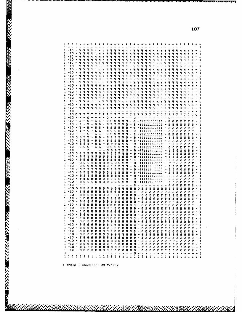
107
-- - - - - - ----- - - - - - - -1 -10 4i 't L U 4i 4t 4~ 4i 4 4~ 4 4i 4i 4 4i 4i 4i 4 4 I L I " LI 4 4 9 I L !1 -10 4i Li Li i LI 4i 4 4 L Li Li Li Li Li L i Li Li L 4 L LI Li 4 Li LI L LI 4 - 11 -10 I i I I i i i i I i I LI i i i I I I LI i LI LI LI I I I - 1-10
1 -10- Li LI 4 4 L 4 4 L LI 4 L L 4 L L 4 4 4 L L 4 4 L 4 Li 4 4 - 1
1 -10 4 L L L 4 4 4 4 4 '4 4 L 4 4 4 4 4 4 L 4 4 4 4 4 L LiL 4 4 - 11 -10 4 4 4 4 Li 4 4 4 4 4 4 L L 4 4 4 4 4 4 4 4 4 L L L L L L - 11 -10 - L 4 i L 4 4 4 L L L L 4 4 4 4 4 4 4 4 4 L L I 4 4 L L L - 11 -10- 4 4 4 4 4 4 4 4 4 4 4 4 L 4 4 4 4 4 4 4 4 L L L L L 4 - 1
1 -10- Li L 4 4 4 4 L L L L L 4 4 4 L 4 4 4 4 L 4 L 4 L L L L L L - 11 -10 - 4 L L 4 L L L L 4 4 4 L 4 L 4 4 L 4 L L L L L i 4 4 L L 4 - 11 -10 - 4 4 L 4 4 L 4 L L L 4 L 4 4 4 4 4 L 4 4 L i L L L I 4 4 L - 11 -10 - L L L L L L L L L L L L L L L L L L L L L L L L L 4 L L L 4 - 11 -10 - 4 4 4 4 L 4 4 L 4 4 4 4 L 4i 4 4 4 L 4 4 L 4 L 4 4 4 4 4 - 11 -10 - L 4 4 4 4 4 4 4 4 L 4 Li 4 L I 4 L L L L L I 4 4 L L - 11 -10- 4 L 4 L L L L L 4 L 4 L 4 4 L L 4 4 L 4 L 4 L 11 -10 - Li LI LI Li Li LI Li LI 4 Li Li LI Li 4 Li Li Li Li LI Li LI Li Li Li LI LI LI LI 4 - 1
* ~~~~~1 -10 - Li 4 4 Li 4 LI Li Li Li Li Li Li Li LI Li Li 4 LI Li LI LI Li Li Li LI LI Li - 1
1 1-10 07777777777777777777777777777770 44 44 44 44 44 -11 -10- --- -------------- 0----------0--------11 -10 0 7 7 7 7 7 7 7 7 7 7 7 7 7 7 7 7 7 7 7 7 7 7 7 7 7 7 7 7 7 0 11 -10 - - - 0 - - - - 0 - - 9 9 - - 0 -1111111111 - 0 2 2 2 2 2 - 11 -10 - 3 - 5 - 6 6 - 9 9 9 9 9 9 - 8 -111111111111 - 2 2 2 2 2 2 2 - 11 -10 - 3 - S - 6 6 - 9 9 9 9 9 9 - 8 -111111111111 - 2 2 2 2 2 2 2 - 11 -10 - 3 - 5 - 6 6 - 9 9 9 9 S 9 - 8 -111111111111 - 2 2 2 2 2 2 2 - 11 -10 - 3 - 5 - 6 6 - 9 9 9 9 9 9 - 8 -111111111111 - 2 2 2 2 2 2 2 - 11 -10 - 5 5 5 - 6 6 - 9 9 9 9 9 9 - 8 -111111111111 - 2 2 2 2 2 2 2 - 11 -10 - 5 5 5 - 5 6 - 9 9 9 9 9 9 - B -111111211111 - 2 2 2 2 2 2 2 - 11 -10 - 5 5 5 - 6 6 - 9 9 9 9 9 9 - 8 -11111111111 - 2 2 2 2 2 2 2 - 11 -10 - 5 5 5 - 6 6 - 9 9 9 9 9 9 - 8 -111111111111 - 2 2 2 2 2 2 2 - 11 -10 - 9 9 - 9 9 - 9 9 9 9 9 9 - 5 -111111111111 - 2 2 2 2 2 2 2 - I1 -10 - 9 9 9 9 9 - 9 9 9 9 9 9 9 - 5 -111111111111 - 2 2 2 2 2 2 2 - 11 -10 - 9 9 9 9 9 9 9 9 9 9 9 9 9 - 8 -111111111111 - 2 2 2 2 2 2 2 - 11 -10 - 9 9 9 S 9 9 9 9 9 9 9 9 9 - 5 -111111111111 - 2 2 2 2 2 2 2 - 11 -10 - 9 9 9 9 9 9 9 9 9 9 9 5 9 - 8 -111111111111 - 2 2 2 2 2 2 2 - 11 -10 - 9 9 9 9 9 9 9 9 9 9 9 9 - B -111111111111 - 2 2 2 2 2 2 2 - 11 -10 - 9 9 9 9 9 9 9 9 9 9 9 9 9 - 8 -111111111111 - 2 2 2 2 2 2 2 - 11 -10 - 9 9 9 9 9 9 9 9 9 9 9 9 9 - 8 -111111111111 - 2 2 2 2 2 2 2 - 11 -10 - 9 9 9 9 9 9 9 9 9 9 9 9 9 - 8 -111111111111 - 2 2 2 2 2 2 2 - 1
1 -10 - 9 9 9 9 9 9 9 9 9 9 9 9 9 - 8 -111111111111 - 2 2 2 2 2 2 2 - 1
1-10 -8---------------------- 2------22 2222-I1 -100 99 9 B 5B 885 58 8 B B 0222 2222222 2 2 22 - 11 -10 - B 888 B 89858 5 85898 - 2 2222 2 222 222 - I1 -10O -555959995955559888-222222 2222222 2 - 11 -10 -S S B 8 B 88 s8 B 88 Bs8 - 222 22 2 222 2 222 2 - 11 -10 -5 8B 8 B B B B B 88 8 2 2 2 2 2 2 2 2 2 2 2 2 2 2 - 11 -10 - B 88 8 8 8 5 8 58 5 9 - 2 2 2 2 2 2 2 2 2 2 2 2 2 2 - I1 -10 - 888 B 8888 8 8 8 5- 22 22 2 2 2 2 222 2 2 - 11 -10 - B B 88 B B 9888 8 - 22 2 2 2 2 2 2 2 22 2 2 2 - 11 -10 - 8 9 8 8 8 8 8 8 B 88 8 - 2 2 2 2 2 2 2 2 2 2 2 2 2 2 - 11 -10 - 9 8 B 8 8 5 8 59 8 8 8 9 8 - 2 2 2 2 2 2 2 2 2 2 2 2 2 2 - 11 -10 - 95598 8 8 5 8 8 8 9 B 8 8 8 - 2 2 22 2 2 2 2 2 2 2 2 2 - 11 -10 - 8 9 B 8 8 5 8 8 8 8 8 8 9 - 2 2 2 2 2 2 2 2 2 2 2 2 2 2 - 11 -10 - 99 8 59 B 8 9 B 5 5 5 8 8 5 - 2 2 2 2 2 2 2 2 2 2 2 2 2 2 - 11 -10 - B 5 5 5 9 5 5 5 a e e e a a 5 - 2 2 2 2 2 2 2 2 2 2 2 2 2 2 - 11 -10 - 9 5 8 8 859 8 8 8 8 8 8 - 2 2 9 2 2 2 2 2 2 2 2 2 2 2 - 11 -10 - 5 8 5 8 8 8 8 8 8 8 8 98 8 59 - 2 2 2 2 2 2 2 2 2 2 2 2 2 2 - 11 -10 - 8 B 8 9 8 8 e 8 8 58 8 8 8 - 222 2 2 2 2 2 2 22 2 2 2 - 11 -10 - 8 8 8 8 8 8 8 B 8 8 8 8 2- 2 2 2 2 2 2 2 2 2 2 - 1i -lo - e s a 8 e e 8 E B 8 B B 8 B 2 2 2 2 2 2 2 2 2 2 2 2 2 2 11 -10 - 9 552 8 8 8 8 B 8 8-1 8 8 8 8 2 2 2 2 2 2 2 2 2 11 -10-9 556895558559-. 2222 2222222222-1
I !s cI Condcrscd AS lct-rlx

-4 .- I~C
---4-i C w CD @ C-1@0M~pw-C~
4-4" CCm@%I
-4 A~o pan@0@ ~@Cmd zad! go ~ ~@04
--- 4 '4 r.-4%j C"
Excrnple I Screen Print of DuOl
% ..

109
10 : 1400 B : 170 7 S70
2 120 CLU 010304 34 410 CDL 010204 4
S 4SO BLD 020304 35 130 BLD 020407 76 60 CLU 040708 B11 1250 BLD 03040S 53 340 BLD 020408 8
Example I Insertion information
-4I
%X
Eampie I Screen Print of Black Plan
E- * Ile
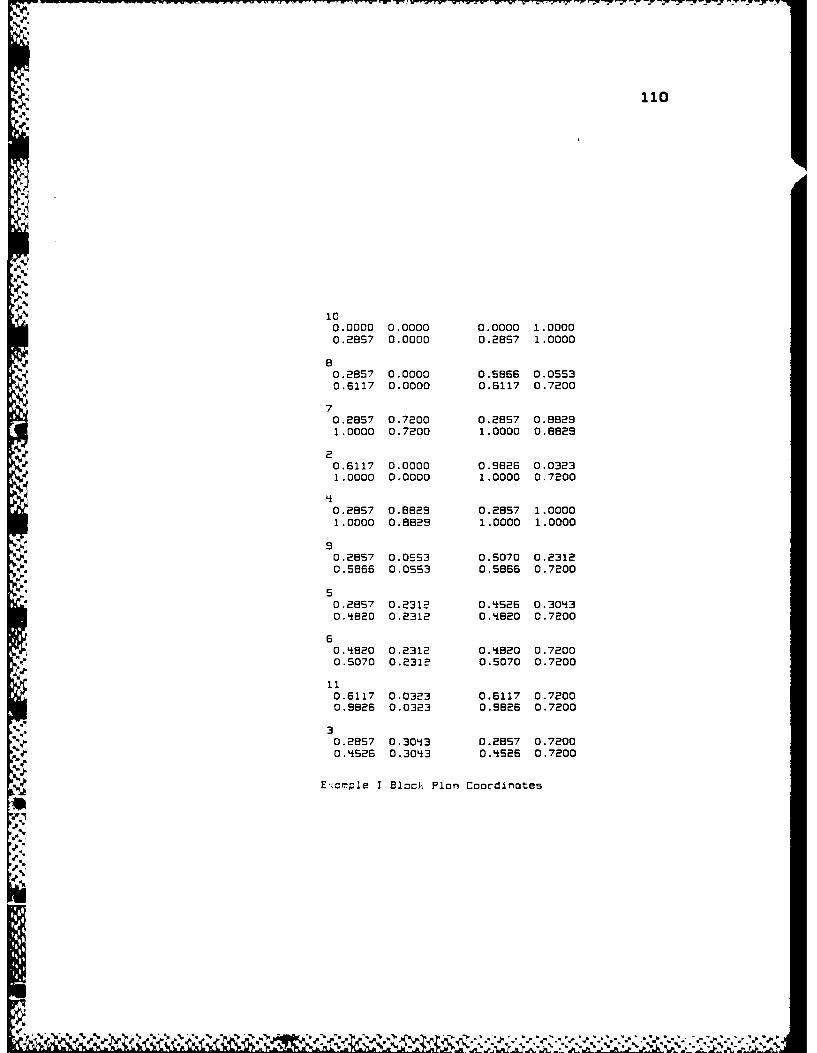
V..O
-
101
0.0000 0.0000 0.0000 1.00000.2657 0.0000 0.2B57 1.0000
B0.2857 0.0000 0.5866 0.05530.6117 0.0000 0.6117 0.7200
70.2857 0.7200 0.2857 0.88291.0000 0.7200 1.0000 0.8829
20.6117 0.0000 0.9826 0.03231.0000 0.0000 1.0000 0.7200
40.2857 0.8629 0.2857 1.00001.0000 0.8829 1.0000 1.0000
90.2857 0.0553 0.5070 0.23120.5866 0.0553 0.5866 0.7200
50.2857 0.2312 0.4526 0.30430.4820 0.2312 0.4B20 0.7200
60.4820 0.2312 0.4820 0.72000.5070 0.2312 0.5070 0.7200
110.6117 0.0323 0.6117 0.72000.9826 0.0323 0.9826 0.7200
30.2857 0.3043 0.2857 0.7200
0.4526 0.3043 0.4526 0.7200
Exomple I Block Plon Coordinotes
1%
-p.6

APPENDIX D
OUTPUT FROM EXAMPLE II
Rcndon number seed (-3276B to Je76 Y? 2You will need to input the filenome For the data you wont to use.
* Would you like o list of Files on the disk [Y/N)' NEnter onW filenume with .DAT for on extension
9 3-12R
IF Wou need an X value other than -1024 enter it at the prompt,if nat press return.?NUMBER OF FACILITIES: 12
1 1 A U U U U U U U U A A2 2 A n 0 E U E I I A U3 3 0 UD 0 00 U AU
-'9 9EEUOOOOu
5 SUEUUUUA6 6 UIOOUU7 70000Ea 8 0U 0U9: IOu
10 :0 U 011 11 X12 12
DELTAHEORON INSERTION ORDER
1 2 3 4 5 E 7 8 9 10 11 12
INSERTING VERTEX 5 IN TRIANGLE 1 2 4 C10204
INSERTING VERTEX 6 IN TRIANGLE 2 3 9 020304
INSERTING VERTEX 7 IN TRIANGLE 5 2 4 O0209
INSERTING VERTEX e IN TRIANGLE 2 3 6 020306
:NSERTING VERTEX 9 IN TRIANGLE 2 3 8 020308
INSERTING VERTEX 10 IN TRIANGLE 2 3 9 0203C
INSERTING VERTEX 11 IN TRIANGLE 1 2 3 010203
INSERTING VERTEX 12 IN TRIANGLE 1 9 S 010905
TOTAL DELTAHEDRON ADJACENCY SCORE IS 619
INCIDENCE MATR!X:
I AUUU ----- AA2 A A 0 E U E I I A-3 O-0-OOUA-
S4 E E U -. . . . U9 E ....- US E - - - - A
SI - -10 --
1112
-,zm=oe !I Cclt:-hcnron Heuristic Output
N1

-C U CDC
CM CMU
_xmpe11 Scree Prin ofDa

113
1 - 2 - 5 S 5 S 5 S 5 5 5 5 5 5 5 S -1212121:21212I121212121 -1
1 2- 5 5 S S 5 5 5 5 5 5 5 5 5 5 5 5 -12121212121212121212121212- 1
1 - 2 - 5 5 S 5 5 5 5 5 5 5 5 5 5 5 5 5 -12121212121212121212121212 - 1I - 2 - 5 5 5 5 5 5 5 5 5 5 5 5 5-5 5 5 -12121212121212121212121212 - 11 2 5 5 S S 5 5 55555 S S 5 5 512121212121212121212121212 11 - 2- 5 5 5 5 S S 5 S 5 5-121212121212121212121212 11 - 2 - 5 S5 5 5 5 S 5 S S 5 S 5 5 -12121212121212121212121212 - 11 - 2 - 5 55 5 5 5 5 5 S 5 5 5 55 -12121212121212121212121212 - 11 - 2 0 5 5 5S S5 5 5 5 5 5555 -12121212121212121212121212 - 1
1 - 2 -- - - - - - - - - - - - - - 5 -12121212121212121212121212 - 11 - 2 - 7 7 7 7 7 7 7 7 7 7 7 7 7 7 - 5 -12121212121212121212121212 - 11 - 2 - 7 7 7 ' 7 7 7 7 7 7 7 7 7 7 - 5 -12121212121212121212121212 - 11 - 2 - 7 7 7 7 7 7 7 7 7 7 7 7 7 7 - 5 -12121212121212121212121212 - 11 - 2.- 7 7 ' 7 7 7 7 7 7 7 7 7 7 - S -12121212121212121212121212 - 1S- 2 - 7 7 7 7 7 7 7 7 7 777 7 7 - -12121212121212121212121212 - 11 2 - 7 7 7 - 7 7 7 7 7 7 7 -7 7 7 - S -12121212121212121212121212 - 1I - 2 - 7 7 7 7 7 7 7 7 7 7 7 7 7 7 - 5 -12121212121212121212121212 - 11 - 2 - 7 7 7 7 7 7 7 7 7 7 7 7 7 7 - 5 -12121212121212121212121212 - 11 -2-776777777777 777-3 33 3 33121212121212 12121212-I
1-2--------------------- -----------------------------11 -20 4 4* 444446-43333344 344 0 1
1-2-----------------------------------------33 3 3 3 3 3 - 11-2-6656566666665-3333333333333333-11 -2- -5566-6-66555 - 333333333333333- 11- 2- 66656 55 6 666-333333333333333 11- 2- 6666 65566 665- 333333333333333- 11 - 2- 6666 6 6666666-333333333333333- 1
1-2 6666566666 56666 333333333333333-11 -2 6 966566666333333333333333 1
1-2-8588658555886-333333333333333-11-2-55565556655555-333333333333333-11 - 2-088S6666556655- 333333333333333- 1
1-20585888558658-8333333333333333-11 -2- 95 5 55 5 55 - 33333333333333- 11 -2 -6 6 6 S 6 6 6 8 6 6 S - 333333333333333- 1
1 -20 o 6 6 6 6 6 6 6 6 6 6 330333333333333333- 1
1-2 6 5S66666666 96 96 33333333333 3333-1
1 -2 6 66 6 6 S6 6 66 63 3 3 33 3 3 33 3 3333 3-1
- 2 -1010101010101010101010101010 - 3 33 3 3 3 3 3 33 3 3 3 3 3 - 11-2 8---B---8-8-8---8-8-----8-8-3--3-3333333333333333-1
1 - 2 033333333333333333333333333333301
1 2 B. B. . . . . . . . . . . . . . . . . . . . . . . . . . . . . .3 3 3 3 3 1
1- 2 -111111111111111111111111111111111111111111111111111111111111 - 11 - 2 -111111111111111111111111111111111111111111111111111111111111 - 11 -2 -11111111111111111111111111111111111111111!11111111111111111 - 11- 2 -11111111111111111111111111111111111111111111111111111111111 - 11- 2 -11111111111111111111111111111111111111111111111111111111111 - 11- 2 -111111111111111111111111111111111111111111111111111111111111 - 1S-2 -111111111111111111111111111111111111111111111111111111111111 - 11 -2 -11111 211111111111111111111111111111111111111111111111111111 - 1
1 -.2 -111111111111111111111111111111111111111111111111111111111111 - 11 -2 -11111111111111111111111111111111111111111111111111111111111 -11 - 2 -111111111111111111111111111111111111111111111111111111111111 - 11 -2 -111111111111111111111111111111111111111111111111111111111111 - 11 -2 -I111111211111111111111111111111111111111111111111111111111111 - 11 - 2 -111111111111111111111111111111111111111111111111111111111111 - 11 - 2 -111111111111111111111111111111111111111111111111111111111111 - 1
1 - 2 -111111111111111111111111111111111111111111111111111111111111 - 11 - 2 -11111111111111111111111111111111111111111111111111111111111 - 1
* ~1111111111111111111111' 11111111111111
E :rIe II :C ~orad AS Ilotrix
Copy available to DTIC does notpipmilt hiUy egible z eroduc
1- 2
1. 2*

2 : 500 3 :0 BOO 150S 4*00 COL 010204* 46 150 ELD 020304i 37 350 BRD 0204105 5B 200 CDR 020306 69 350 CDJR 020308 810 350 CDR 020309 911 200 CDR 010203 312 600 CRU 010't05 S
Example 11 Insertion information
L -4
E: omple 11 Screen~ Print of Block Plan

20.0000 0.0000 0.0000 1.00000.58B'~ 0.0000 015B8*8 1.0000
30.584t8 0.0553 0.8578 0.184S1.0000 0.0553 2.0000 O.S77S
4j
0.58&18 0.5775 0.58Li8 0.61971.0000 0.5775 1.0000 0.6197
0.74*24 0.6795 0.58*6 1.00000.9155 0.6197 0.815S 1.0000
60.56'iB 0.5214t 0.SB'i8 0.577S0.8976 0.521h 0.5976 0.5775
70.S8L18 0.6197 0.84 0.87950.74A24 0.6197 0.74*24 0.879S
A 8*O.se'te 0.Lt4~66 0.S84*8 0.521'i
0.6575 0.446*6 0.8976 0.521*
90.S84~8 0.3157 0.58L18 0.I4t560.8575 0.3157 0.8976 0.44'56
10O.58*8 0.18*9 0.58'*8 0.31570.8976 0.184S9 0.8976 0.3157
110.58'k8 0.0000 0.SB8 0.05631.0000 0.0000 1.0000 0.0553
120.8155 0.5157 0.8155 1.00001.0000 0.6197 1.0000 1.0000
Exam~ple II Bloc); Plan Coordinates

APPENDIX E
OUTPUT FROM EXAMPLE IIIRUNRandom number seed (-32768 to 32767)? 1You will need to input the filename fdr the data you want to use.Would you like a list of Files an the disk CY/N3? nEnter any filename with .DAT for an extension? FOULDS
If you need an X value other than -1024 enter It at the prompt.if not press return.? -1NUMBER OF FACILITIES: E1 : lO0000000000AOOOOA0002: E000a0a a000a a00a0003: 3 E 000000000000000000
S0 0 0000O0 000000005: 000 00 0 0a00a006: E 0000000 000000007 : 70000000000000009: B100UXOO00I IOAE
9 : S000XOO0 0A0 1110: 1 00000000000 E
." 11 : 1 0 a 0 0 0 0 0 0 0 0 0
2 1:2 U 0 0 0 0 A E 0 013: 13 0 U a U X 0 a 0 01 : 1t 100000 015: 15 0 1 1 U U U U16: 160 a 0 0017: 17 U U 00018: 101 0 0 E19: 19 I U U2O : BOX I21 E1 A22 22
DELTAHEDRON INSERTION ORDER
1 19 E 21 8 12 10 9 13 18 EO 3 4 6 7 14 15 B S 11 16 17
INSERTING VERTEX B IN TRIANGLE 19 BE 21 020304
INSERTING VERTEX 2 IN TRIANGLE 1 19 el 01004
INSERTING VERTEX 10 IN TRIANGLE 8 22 el 05030
INSERTING VERTEX 9 IN TRIANGLE 19 21 B OEO40S
INSERTING VERTEX 13 IN TRIANGLE- I E 21 010304
INSERTING VERTEX 10 IN TRIANGLE 19 22 6 020305
INSERTING VERTEX eO IN TRIANGLE 1 19 12 O0206
INSERTING VERTEX 3 IN TRIANGLE 6 el 10 S0407
INSERTING VERTEX 4 IN TRIANGLE 3 e1 3 OS0I1B
INSERTING VERTEX 6 IN TRIANGLE 8 10 3 0SO71
116

117
INSERTING VERTEX 7 IN TRIANGLE 5 10 3 14i0712
INSERTING V.ERTEX 14 IN TRIANGLE 20 19 12 110206
INSERTING VERTEX 15 IN TRIANGLE 19 22 8 100305
INSERTING VERTEX 2 IN TRIANGLE e 10 6 050714i
INSERTING VERTEX S IN TRIANGLE 8 6 2 0514*18
INSERTING VERTEX 11 IN TRIANGLE 1 21 13 0104t09
INSERTING VERTEX 15 IN TRIANGLE B 3 'i 051213
INSERTING VERTEX 17 IN TRIANGLE 15 22 8 170305
TOTAL BELTAHEORON ADJACENCY SCORE IS 515
INCIDENCE MATRIX:
1------------------O A-------A 0 02 ~~~~ -- 0 0 0------ --- -- -- --
3 E 00 0-0--- - - - -- --
5 0 -0-------- ------ - -- -- -- --6 E 0-0--------------- --7 - 0------- --- - -- -- -- --B 10- - - - 0 DDI I A E
:0 - - - - - - - - - - E A10 - ------------- 0
12 1 - -- A E -13 - - - - - - -0 a14i - -- -0 0- -
1617 -- - -01B I -- Eis I U U2021 A22
!.~;eI! Deltahedron Heuristic Output

4
-4 CD u-W Cm M_ -4 0%D%
_wlcDO q I IC U11. u -4I U2C I
U-4J c m % -- ~~ IC
C%3 0-14 = =S ' CD S= =
C%3 toO @. C3@0z @0 I=CD @0m% @0@012 ~@0U 4C4@ "~ cwp co C%
@0- -%3 -4-- %Dv co
Ex @0PeIIIS.-e rn FDa
@0 (YI @0 @0 I uI -I
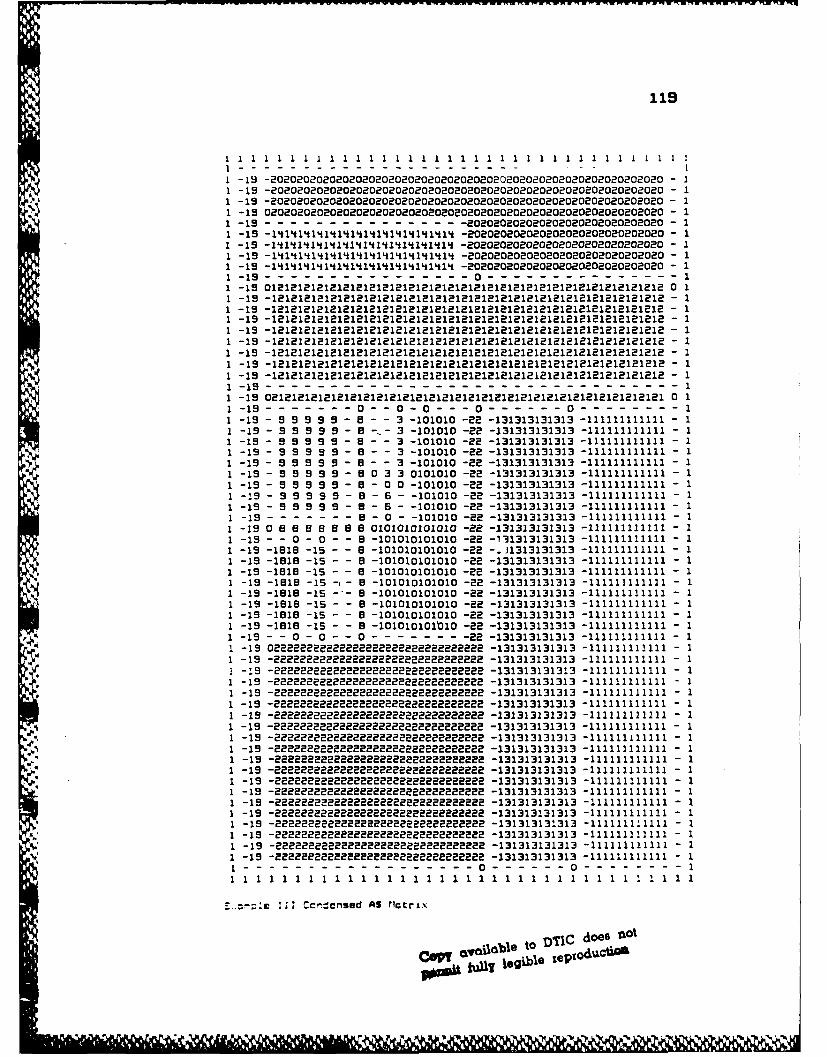
119
--- -1 -19 -2020202020202020202020202020202020202020202002020202020200 - 11 -19 -202020202020202020202020202020202020202020202020202020202020 - 11 -19 -202020202020202020202020202020202020202020202020202020202020 - 11 -15 0202020202020202020202020202020202020202020202020202020202020 - 1
1 -19 -20200802020202020202020202020 - 11 -19 -14141414141411111114 -202020202020202020202020202020 - 1
1 -19 -14141414111111111 -202020202020202020202020202020 - 11 -19 1 41111111114 -202020202020202020202020202020 - 11 -19 -14141414141414141414141 -202020202020202020202020202020 - 1S-1--1 01 -19 012121212121212121212121212121212121212121212121212121121212 0 11 -19 -121212121212121212121212121212121212121212121212121212121212 - 1
1 -19 -121212121112121818181818181812181818121212181218181818181 - 11 -19 -1212121212121212121218121212121212121212121212121121211212 - 1
1 -19 -1212121212121121212121212121212121212121212121211212121212 - 11 -19 -12121212121812121212121212212121212121218121212121212121212 - 1
1 -19 -12121212121212121211111111112121211212121212121212 - 11 -19 -12121218111111112121112121I121I121212121212121212 - 1
1 -19 -1-1- 1-11-1 1-18--181-1-1111-1 i1-i11112128121 - 11-19-11
1 -19 02121212121212121212121212121212121121211211121121212121 0 1
1 -1 - 0 -- 0 -0 --- 0 -0 -11 -19 - 9 9 9 9 9 - 8 - - 3 -101010 -2 -131313131313 -111111111111 - 1
1 -19 - 9 9 9 9 9 - 5 -,- 3 -101010 -2 -131313131313 -111111111111 - 11 -19 - 9 9 9 9 9 - 8 - - 3 -101010 -88 -131313131313 -111111111111 - 11 -19 - 9 9 9 S 9 - 8 - - 3 -101010 -88 -131313131313 -111111111111 - 11 -19 - 9 9 9 9 9 - 8 - - 3 -101010 -2 -131313131313 -111111111111 - 11 -19 - 9 9 9 9 9 - 5 0 3 3 0101010 -22 -131313131313 -111111111111 - 1
1 -19 - 9 9 9 9 9 - 8 - 0 0 -101010 -28 -131313131313 -111111111111 - 11 -19 - 9 9 9 S 9 - 8 - 6 - -101010 -22 -131313131313 -111111111111 - 11 -19 - 9 9 9 9 9 - 8 - 6 - -101010 -22 -131313131313 -111111111111 - 11 -19- - - ------ - 0 - -101010 -2 -131313131313 -111111111111 - 11 -19 0 8 8 8 8 5 8 8 0101010101010 -22 -131313131313 -111111111111 - I
1 -19 - - 0 - 0 - - 8 -101010101010 -88 -131313131313 -111111111111 - 11 -19 -1515 -15 - - 8 -101010101010 -82 -.31313131313 -111111111111 - 11 -19 -1518 -15 - - 8 -101010101010 -2 -131313131313 -111111111111 - 11 -19 -1818 -15 - - 5 -101010101010 -88 -131313131313 -111111111111 - 11 -19 -19 -15 -- B -101010101010 -22 -131313131313 -111111111111 - 11 -19 -1818 -15 - 8- 5 -101010101010 -22 -131313131313 -111111111111 - 11 -19 -1818 -15 - - 8 -101010101010 -28 -131313131313 -111111111111 - 11 -19 -1818 -15 - - B -101010101010 -88 -131313131313 -111111111111 - 11 -19 -5185 -15 - - 8 -101010101010 -2 -131313131313 -111111111111 - 11 -19 - - 0 - 0 - - ------- -131313131313 -111111111111 - 11 -19 022222e2222222222222222222 -131313131313 -111111111111 - 11 -19 -8228222888828222228228822888 -131313131313 -111111111111 - 11 -19 -22222222 8222282282828288 -131313131313 -111111111111 - 11 -19 -222222222222222822822228282 -131313131313 -111111111111 - 11 -19 -2 2222228828 2228888888 -131313131313 -111111111111 - 11 -19 -2222222222228222222222822282 -131313131313 -111111111111 - 1
1 -19 -288228222228222222888882Z288 -131313131313 -11111111 1 - 1
1 -19 -282222288882228288888888 -131313131313 -111111111111 - 1
1 -19 -82222ZE28888822222228888888 -131313131313 -111111111111 - 11 -19 -222222222822228222222228 -131313131313 -111111111111 - 11 -19 -8228888888882228222222822 -131313131313 -111111111111 - 11 -19 -8288888822828 2228888888888 -131313131313 -111111111111 - 11 -19 -2822222222288888882222882288 -131313131313 -111111111111 - 11 -19 -2222222222222228822888888 -131313131313 -111111111111 - 11 -19 -22222222 28888222 -131313131313 -111111111111 - 11 -19 -222 222222882 222 288 28 -131313131313 -111111111111 - 11 -19 -2222228282228222e2882288822 -131313131313 -111111111111 - 11 -19 -222222222 228222282888 -131313131313 -111111111111 - 1
1 -19 -2 8 222 22 22222888 -131313131313 -111111111111 - 11 -19 -8882222222 2 2888888888EZ88888 -131313131313 -111111111111 - 1
-I 0 - - - - - - 0 - - - - - - - - 1
z1, Ccrdamsed AS rtotrix
CP , oilble to DTIC does Uot
CWT.a legible eptoducs

120
15 : 3000 22 : 2500 21 : 008 1500 BLD 020304 312 1000 CDL 010204 410 2250 CLU 030405 55 1500 BLD 020405 S13 3500 CLU 010304 318 3360 BRD 020305 520 3000 CDL 010206 63 1S2S LD 040507 74 1650 BLD 040512 126 64O CDR 050712 127 2000 CLU 071214 1414 7000 BRD 020611 1115 750 CRU 030510 102 1075 050714 05 1000 S141B 011 2200 CLU 010409 S16 00 051213 017 1755 CRU 030517 17
Example III Insertion Information
-4M
"WI
4-
E.xample III Screen Print of Block Plan with three Facilities not included

121
n nnnn n. rrln n.nrln 1 15900,0'53 O.OUUU 1,.01bi l.UUU0
220.0753 0.0000 0.757 0.045V0.767 0.0000 0.7567 0.6905
O.0'S3 0.690S 0.0753 0.'0131.0000 O.6505 1.0000 0.7013
a0.0753 O.SS14 0.4157 0.5770.4319 O.SS1 0.41319 0.6905
120.0753 0.7013 0.0753 0.729S1.0000 0.7013 1.0000 0.7m65
100.4319 0.0456 0.6994 0.15660.7457 0.05S6 0.74S7 0.6105
90.0753 0.559"! 0.073 0.690S0.4157 0.55'7? 0.1S? 01690S
130.'92' 0.0000 0.7 57 0.6900.9200 0.0000 0.9600 0.6905
180.0753 0.0452 0.0753 0.551t0.656O 0.05S2 O.6tO 0.5514
0.65490 0.95S? 0.07S3 1.00001.0000 0.7e6s 1.0000 1.0000
30.4319 0.3913 O.65eO 0.47400.694 0.3913 0. 695 0.690S
0.531O 0.V748 0.319 0.69050.6650 0.4740 0.6650 0.6905
61 0.315 0.126 0.4315 0.3J130.4965 0.156 0.5965 0.3913
70.4965 0.1426 0.4965 0.39130.6954 0.1426 0.595 0.3913
150.0753 0.705 0.07S3 0.90570.8490 0.7695 0.090 0.957
5
0.0000 0.0000 0.000 0.00000.0000 0.0000 0.0000 0.0000
60.0000 0.0000 0.0000 0.00000.0000 0.0000 0.0000 0.0000
11
0.000 0.0000 O.S00 0.6900.0000 0.0000 0.0000 0.600
111 0000 0.0000 1.0000 0.6050
0.0000 0.0000 0.0000 0.0000'I- 17
0.6292 0.025 O69 O.SS0.3646 0.0526 0 3666 0 5515
r.'ole III B lck. Plan Coordinctes *it. three rocilitaes not incIuded
VCOPi Ov a ilgb l '? to DTIC does notpsm ~jly legible zspiodWdC'O

--- 4
-c H-4-
Co -
cl-I
-4C%
- .... Ic~~I!Sz:.-c- Fr-nt cfr Complete Block Plan~

S.
123
-wu
0,0000 0.0000 0.0000 1.0000U.0'0 O.OUUU O.U/U5 I.UUU
2p0.0-09 0.0000 0.764 0.09120.8102 0.0000 0.8102 0.7100
210.0709 C.7100 0.0709 0.72011.0000 0.7100 1.0000 0.7201
a0.0709 0.5662 0.3805 0.5725
0.3948 0.5662 0.3948 0.7100
120.0,09 0.7201 0.0709 0.7961.0000 0.7201 1.0000 0.7455
100,3948 0.0412 0.7252 0.11680.76-4 0.0912 0.7674 0.7100
S0.0709 0.572S 0.0709 0.71000.3805 0.5725 0.3805 0.7100
130.8102 0.0000 0.8102 0,71000.5268 0.0000 0.9268 0.7100
18d 0.0709 0.012 0.070S 0.56620.2222 0.0912 0.2222 0.5SS2
0.8482 0.99 0.0709 1.00001.0000 0.7956 1.0000 1.0000
30.3s95 0.9592 0.6950 0.51630,7252 0.5942 0.7252 0.7100
90.3998 O.SS1 0.3948 0.71000.6450 0.5541 0.690 0.7100
60.5611 0.411' 0.3998 0.45420.5851 0.1168 0.5851 0.5942
7o.1si 0.1168 0.5851 0.59420.7252 0.1168 0.7252 0.5942
190.0709 0.7456 0.0709 0.95840.892 0.7456 0.8482 0.5584
is0.2222 0.0412 0.2222 0.56620.2560 0.0912 0.2560 0.5662
20.3948 0.1168 0.3998 0.26960.561. 0.1168 0.5611 0.2696
s0 39498 0.2696 0.3948 0.41170,561 0.2696 0.SI 0.4117
11C9268 0.0000 0.9268 0.7100
1.0000 0.0000 1.0000 0.7100
160.3948 0.5163 0.3948 0.5910.6150 0.5163 0.690 0.5591
170.2560 0.0412 0.2560 01.560.3350 0.012 0.33S0 0.5662
E[z 'e III Ccmplmtm Block Pln- Coardsmotes
Cop!r GvoiA'2l. to DTIC doesliU , 1 ) g1ee : °

REFERENCES
Armour, G. C., and Buffa, E. S., A Heuristic Algorithmand Simulation Approach to Relative Location ofFacilities, fl~gWD~3~,Vol. 5, No. 1,1963, pp.29'I-309.
Eades, P., Foulds, L. R., and Giffin, J. W., AnEfficient Heuristic for IdentifUing a Maximum WeightPlanar Subgraph, CQbOt~Q_1t6QQXLecture Notes in Mat. No. 952, (Springer-Verlag,Berlin3, 1982, pp.239-251.
Euler, L., Demonstratia nonnullarum insigniumproprietatum quibus solida hedris planis inclusa auntpradita, ~gi~w~g ji~..Et~JVol .',1752, pp.1'*0-160 1752 1QgmgC.QQMUjg, Vol. 26,pp. S'k-1083.
Foulds, L. R., Gibbons, P. B., and Giffin, J. W.,Facilities Lauout AdiocencU Determination: AnExperimental Comparison of Three Graph Theoretic
4 ~Heuristics, Omgio.EurbVol. 33, No. 5,1965, pp. 1051-1105.
Foulds, L. R. and Robinson, D. F., Graph TheoreticHeuristics for the Plant Layout Problem,lueutoQ-~cQ-E-rd~inRa~rbVol. 16, 1976, pp. 27-37
Francis, R. L., and White, J. A., EQQ11tUWGU9ULgDaLgggn~o.~gi~ggLgprg~bPrentice-Hall Inc.,
Englewood, Ca., 1974*.
Giff in, J. W., gcab-bgri...ImbD QU.: gtEEQGgIjtie:Lgi.&gu, Doctoral Dissertation, UniversitU ofCanterburU, Christchurch, New Zealand, 1984*
Giff in, J. W. and Foulds, L. R., A Graph-TheoreticHeuristic for Minimizing Total Transportation Cost inFacilities Lauout, IntmrBgt19gogJourD21_gfErodugt1ga.Hu3Bgrgb. Vol. 23, No. 6, 1985,pp. 124*7-12S7.
1 24

~125
Giffin, J. W. and Foulds, L. R., Improved Graph TtieoreticTechniques for Facilities Lagout, EurQgpC.oIQurnOgfurgtQgnO EnQ@ugrb, [to appear], 1986.
Hopcroft, J. E. and Tarjan, R. E., Efficient PlanaritUTesting, J_ JiLI Vol. 21, 1974, 5t-B568.
Xoopmans, T. C., and Beckmann, M., Assignment problemsand the location of economic facilities,QwQnmetiQQ, Vol. 25, 1957, pp. 52-76.
Lee,R. C., and Moore, J. M., CORELAP-Computerized
Relationship Laout Planning, Jg rDg_&IDdUtrigj'DgInvariDg, Vol. 18, No. 3, 1967, pp. 195-200.
Muther, R., Sustematic Lauout Planning, Jndu5€tig1Edwco _IoD- itUtz, Boston, Mass., 1961.
Roth, J., HashimshonW, R., and Wachman, A., Turning aGraph into a Rectangular Floor Plan, OUildiDg_gDdEnyirnmaDt, Vol. 17, No. 3, 1982, pp. 163-173.
Seehof, J. M., and Evans, W. 0., Automated Laoout DesignProgram, IbJgurDgolgIhdutriogl-EDgDur iDg,Vol. 18, No. 12, 1967, pp. 690-695.
WhitneU, H., A Theorem on Graphs, 8nn,_gUtb,, Vol. 32,1931, pp. 378-390.
."
%,

-.--.---.----------- wM- Is- - sat.. - aemsra
.g.rF. I