Embed Size (px)
Citation preview

SHENZHEN XILIN ELECTRIC TECHNOLOGIES CO., LTD.
EH600 S Series Inverter
User's manual
V1.3
Th
e co
nte
nt
of
the
ma
nu
al
wo
uld
be
up
da
ted
wit
ho
ut
prio
r n
oti
ce.
R

EH600S series inverter, presented by ShenZhen xilin Electrical Technology Limited
Corporation, is a new generation of high performance.It is a revolutionary product integrated
with general ,personal and professional demands of customer. It has practical PI , simple
PLC flexible input and output terminals paramter save selection when power-off ,、 、
main/auxiliary reference control, frequency swing control , innovative exact stop mode
(length/counter/time control) ,in-line modbus standard agreement , perfect protection for
user password. So it can supply high-integration project for customer in equipment
industry. It is valuable to reduce system costs and improve the reliability of the system.
EH600S meets customers’ environmental needs , such as low noise, low electromagnetic
interference by optimizing the PWM controlling technology and the unitary design of
electromagnetic compatibility.
1 Check whether there is any damage occurred during transportation ; whether there
is any damage or falling in the components ; whether the main body is bumped .
、
2 Check whether the model and the rated values on the nameplate of the inverter are、
in accordance with your order . The box contains the product , and operation manual for
the user .
The manual provides the guidance for installation , wiring , parameter configuration ,fault
diagnosis and debugging , relevant concerns for daily maintenance . In order to correctly install
and operate EH600 series inverter thus to enable them to play their predominant capability ,
please read the manual thoroughly and keep it carefully and deliver it to the user of the equipment .
Upon unpacking , please confirm the followings :
Our corporation is strict in manufacturing , packing and quality assurance system ,
but if you find some missing inspections , please contact our corporation or the supplier
as soon as possible .
Preface

Contents
Preface............................................................................................................................i
Chapter 1 Safety and Cautions.......................................................................................1
1.1 Safety Cautions.....................................................................................................1
1.2 Cautions...............................................................................................................4
Chapter 2 Product Information.....................................................................................6
2.1 Designation Rules................................................................................................ 6
2.2 Nameplate............................................................................................................6
2.3 EH600S Inverter Series.........................................................................................7
2.4 Technical Specifications.......................................................................................7
2.5 Physical appearance and installing dimensions of inverter and operation panel..........10
2.6 Optional Parts.......................................................................................................13
2.7 Routine repair and Maintenance of inverter...........................................................13
2.8 Instructions on Warranty of inverter.......................................................................15
2.9 Prototyping Guide................................................................................................15
2.10 Guide to Prototyping of Brake Components.........................................................16
Chapter 3 Mechanical and Electric Installation...........................................................17
3.1 Mechanical Installation........................................................................................17
3.2 Electrical Installation..........................................................................................19
Chapter 4 Operation and Display.................................................................................29
4.1 Introduction to Operation and Display Interface ....................................................29
4.2 Description of Function Code viewing and Modification methods...........................31
4.3 Method of Viewing Status Parameter.....................................................................32
4.4 Digital Setup Modify on-line................................................................................32
4.5 Password Setting.................................................................................................32
4.6 Suggestive Information........................................................................................33
Chapter 5 Function Parameter Table...........................................................................34

Chapter 6 Parameter Description...............................................................................64
Group F0: Basic Function...............................................................................................64
Group F1: Motor Parameters...........................................................................................70
Group F2: V/F Control Parameters...................................................................................71
Group F3: Input Terminal................................................................................................75
Group F4: Output Terminal..............................................................................................84
Group F5: Start and Stop Control ...................................................................................88
Group F6: Keyboard and Display.....................................................................................92
Group F7: Auxiliary Function.........................................................................................96
Group F8: Fault and Protection.......................................................................................100
Group F9: PID Function.................................................................................................103
Group FA: Swing Frequency Fixed length Count and Fixed time.................................109、 、
Group FB: Multi-speed Function and Simple PLC Function................................................114
Group FC: Communication Parameters............................................................................117
Group FD: Particular Function..........................................................................................118
Group FV: Status Parameter............................................................................................119
Chapter 7 Fault Diagnosis and Solution.......................................................................120
7.1 Fault Alarm and Countermeasures.............................................................................120
7.2 Common Fault and the Resolution.............................................................................129

1
!
Chapter 1 Safety and Cautions
Chapter 1 Safety and Cautions
Safety Definition:
1.1 Safety Cautions
1.1.1 Before Installation
Safety cautions are divided into two types in this manual :
Danger : Danger arising due to improper operations may cause severe hurt or even death .
Caution : Danger arising due to improper operations may cause moderate hurt or light hurt
or equipment damage .
!
!
To make sure your body equipment and property are safe , please read this chapter thoroughly
before using the inverter .
、
1.1.2 During Installation
!
Danger
● Do not use the damaged inverter or inverter with missing parts, or there may be risk of
injury.
Danger
● Mount the inverter on incombustible surface like metal, and keep away from
flammable substances! Otherwise it may cause fire.
!
Caution
● When more than two inverters are to be installed in one cabinet, please pay attention to
Electrical installation) to
● Do not drop the lead wire stub or screw in the inverter, or the inverter may be damaged!
the installation locations (refer to Chapter 3 Mechanical and
ensure the heat sinking effect.

1.1.3 During Wiring
! Danger
● Operation shall be performed by the professional engineering technician, otherwise
●
●
●
A circuit breaker must be installed between power supply and the inverter, otherwise
Make sure the power is disconnected prior to the connection, otherwise there will be
The earth terminal shall be earthen reliably, otherwise there will be danger of electric
there will be danger of electric shock!
there will be danger of electric shock!
danger of electric shock!
shock!
! Caution
● Do not connect the input terminals with the output terminals (U, V, W), otherwise the
● The wire size should be determined according to the manual, otherwise accident may
inverter may be damaged!
occur!
1.1.4 Before Power-on
! Danger
● Please confirm whether the power voltage class is consistent with the rated voltage of
are correct, and
whether the connecting line is
the inverter and whether the input/output cable connecting positions
check whether the external circuit is short circuited and
firm, otherwise the inverter may be damaged!
danger of electric shock!
● The cover must be well closed prior to the inverter power-on, otherwise there will be
! Caution
● Dielectric strength test had been done at factory. Therefore, you needn’t to test it again.
● Whether all the external fittings are correctly connected in accordance with the circuit
provided in this manual.
Chapter 1 Safety and Cautions
2

1.1.5 Upon Power-on
1.1.6 During the operation
1.1.7 During repair
! Danger
● Do not open the cover of the inverter upon power-on, otherwise there will be danger of
● Do not touch the inverter and its surrounding circuit with wet hand, otherwise there will
electric shock!
be danger of electric shock!
● Do not touch the inverter terminals, otherwise there will be danger of electric shock!
! Caution
● Do not change the factory settings at will, otherwise the equipment may be damaged!
! Danger
● Do not approach the equipment when choosing restart function, otherwise there will be
danger of injury!
otherwise personal injury or equipment damage may be caused!
●
●
Do not touch the fan and the discharging resistor, otherwise you may get burnt!
Detection of signals during the operation shall be conducted by qualified technician,
! Caution
● Do not start and shut down the inverter by connecting and disconnecting the contactor,
otherwise the equipment may be damaged!
! Danger
● Do not repair and maintain the equipment with power connection, otherwise there will
be danger of electric shock!
Chapter 1 Safety and Cautions
3

1.2 Cautions
1.2.1 Motor Insulation Inspection
When the motor is used for the first time or when it is reused after being kept, motor insulation
inspection shall be conducted. It is recommended to use the 500V megameter, and the insulating
resistance measured shall be at least 5M !Ω
1.2.2 Thermal Protection of Motor
1.2.3 Running with Frequency higher than Standard Frequency
1.2.4 Vibration of Mechanical Device
1.2.5 Voltage-sensitive Device or Capacitor Improving Power Factor at the Output Side
If the ratings of the motor doesn't match those of the inverter, especially when the rated
power of the inverter is higher than the rated power of the motor, the relevant motor protection
parameters in the inverter shall be adjusted, or thermal relay shall be mounted to protect the motor.
If the user needs to run the inverter with the frequency higher than 50 Hz, please take the
resistant pressure of the mechanical devices into consideration.
If the inverter encounters the mechanical resonance point at certain output frequencies,
can be avoided by setting the skip frequency parameters in the inverter.
which
Since the inverter output is PWM wave, if the capacitor for improving the power factor or
voltage-sensitive resistor for lightening protection is installed at the output side of the inverter,
it’s easy to cause instanta eous over current in the inverter, whichn may damage the inverter.
Don’t use it.
1.2.6 Switching Devices like Contactors Used at the Input and Output terminal
If a contactor is installed between the power supply and the input terminal of the inverter,
it is not allowed to use the contactor to control the start/stop of the inverter. If usage of this
contactor is unavoidable, it shall be used with interval of at least one hour. Frequent charge
and discharge will reduce the service life of the capacitor inside the inverter. If switching devices
like contactor are installed between the output terminal and the motor, it shall ensure that the on/off
operation is conducted when the inverter has no output, otherwise the modules in the inverter
may be easily damaged.
Chapter 1 Safety and Cautions
4

1.2.7 Change Three-phase Input into Two-phase Input
1.2.8 Altitude and Deration
It is not allowed to change the three-phase inverter into two-phase one . Otherwise , it may cause
fault or damage the inverter .
1.2.9 Adaptable Motor
In areas with altitude of more than 1,000 meters, the heat sinking effect of the inverter may turn
poorer due to rare air. Therefore, the derating using is necessary. Please contact our company for
technical consulting in case of such condition.
The cooling fan and the rotor shaft of the non-variable-frequency motor are coaxial connection.
When the rotating speed is reduced, the cooling effect will be poorer. Therefore, a powerful
exhaust fan should be installed or the motor should be replaced with variable-frequency motor
to avoid the over heat of the motor.
Chapter 1 Safety and Cautions
5

20 0.7 G
C
G
MOD L: EH620 S 0.7G
INPUT:
OUTPUT:
S/N:
E
MADE IN CHINA
AC1PH 220V 8.2A50/60Hz
AC3PH 220V 0~1500Hz 4.7A
SHENZHEN XILIN ELECTRIC TECHNOLOGIES CO.,LTD.
Chapter 2 Product Information
2.1 Designation Rules
2.2 Nameplate
Inverter Series
Mark
Mark
Mark
Null None
only brake unit
Mark
Voltage Level
Brake Unit
Function Type
Function Type
GeneralAdaptable MotorPower (kW)
Corresponding Relationship
Model of the inverter
Rated input voltagefrequency and current
,
Rated output voltage ,frequency and currentBar code
SimpleS
Single phase 220VThree-phase 380V40
20
Chapter 2 Product Information
S
Mark 0.2 0.4 0.7 1.5
Motor Power(kW)
0.2 0.4 0.7 1.5
6
2.3 EH600 InverterS Series
InverterModel
Power Capacity(kVA)
Input Current(A)
Output Current(A)
Adaptable Motor(kW)
EH620S 0.2 0.6 3.2 1.8 0.2
EH620S 0.2 1.0 5.4 3.0 0.4
EH620S 0.2 1.5 8.2 4.7 0.75
EH620S 0.2 1.0 2.9 1.5 0.4
EH620S 0.2 1.5 3.4 2.3 0.75
EH620S 0.2 3.0 5.0 3.7 1.5
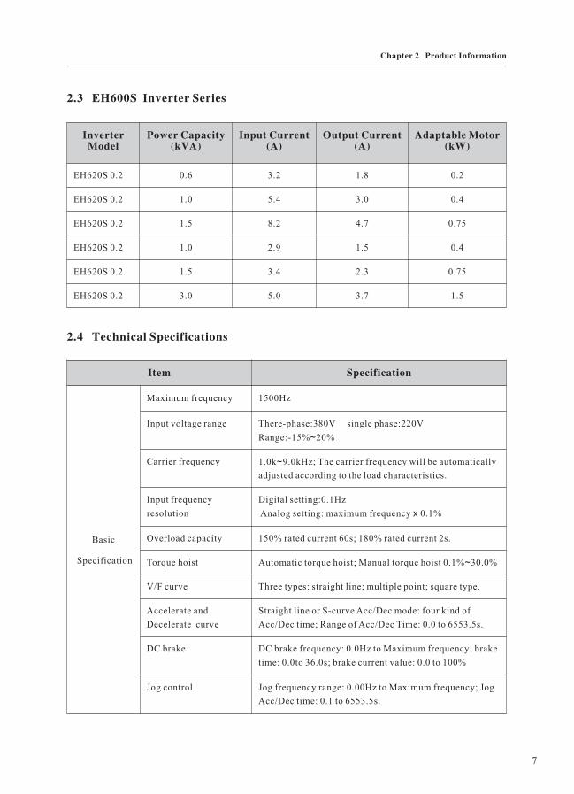
2.4 Technical Specifications
Item Specification
Basic
Specification
Maximum frequency 1500Hz
Input voltage range There-phase:380V single phase:220V
Range:-15% 20%~
Carrier frequency 1.0k 9.0kHz; The carrier frequency will be automatically
adjusted according to the load characteristics.
~
Input frequency
resolution
Digital setting:0.1Hz
Analog setting: maximum frequency 0.1%x
Overload capacity 150% rated current 60s; 180% rated current 2s.
Torque hoist Automatic torque hoist; Manual torque hoist 0.1% 30.0%~
V/F curve Three types: straight line; multiple point; square type.
Accelerate and
Decelerate curve
Straight line or S-curve Acc/Dec mode: four kind of
Acc/Dec time; Range of Acc/Dec Time: 0.0 to 6553.5s.
DC brake DC brake frequency: 0.0Hz to Maximum frequency; brake
time: 0.0to 36.0s; brake current value: 0.0 to 100%
Jog control Jog frequency range: 0.00Hz to Maximum frequency; Jog
Acc/Dec time: 0.1 to 6553.5s.
7
Chapter 2 Product Information

Item Specification
Basic
specification
Simple PLC Multi-
speed running
It can realize a maximum of 16 segment speed running via the
built-in PLC or control terminal.
Automatic voltage
regulation(AVR)
It can keep constant output voltage automatically in case of
change of mains voltage.
Individualized
function
S key Programmable key: meet the individual need.
Realize the jog/reverse command and clear data at exact stop.
Wobble frequency
control
Multi-triangle wave frequency
Exact stop control There are three exact stop modes: counter, fix-length,fix-time.
Input/Output
features
Running command
channel
There are three channels: operation panel, control terminal,
serial port.
Frequency source Nine frequency sources, auxiliary frequency sources. It can
implement micro turning and synthesis of auxiliary frequency.
Input terminal Five digital input terminals(X1 X5). X5 can also be used as
pulse input terminal; One analog input terminal: can be used as
voltage or current input.
~
Output terminal One OC output terminal, one relay output terminal; One
analog output terminal, AO output: 0/2 10V.~
Display and
operation
Operation panel
display
It can display 26 kinds of parameters, such as preset frequency,
output voltage, output current. etc.
Two methods for reading the status parameters are provided.
Double-rank LED
operation panel
(select component)
It can display the debugging result when you are setting
parameter, and it is convenient to monitor two status
parameters.
Protection function Output phase failure protection, over current protection, o
voltage protection, under voltage protection, over heat
protection, overload protection. etc.
ver
Environment
Application
environment
Indoor, free from direct sunlight, dust, corrosive gas,
combustible gas, oil smoke, vapor, drip or salt.
Altitude Lower than 1,000m
Ambient
temperature
-10 ~ 40 ( derated when used in the ambient temperature
of 40
℃ +
~
℃
℃ 0℃.5
8
Chapter 2 Product Information

Item Specification
Environment
Humidity Less than 95%RH, without condensation.
Vibration Less than 5.9m/s (0.6g).
Storage temperature -20 ~ 60℃ + ℃
9
Chapter 2 Product Information

2.5 Physical appearance and installing dimensions of inverter and operation panel
1) Physical Appearance
Operation panel
Cabinet-cover
Small cover plate
Fig.2-1 Physical Appearance of Inverter
Input/Output port
Bottom installation hole
Fan
Guideway
D
B
W1W
H1
H
Fig 2-2 Physical dimensions and mounting dimensions of Inverter.
10
Chapter 2 Product Information

POWER When switch on, it lights; when cut off the power, the lights out.
RUN When it is ON, it indicates the inverter is in rotation status; when it is OFF,
it indicates the inverter is in stop status.
Power indicator
Run indicator
POWER
RUN
Extra-linked line: parallel
the rear appearance of the keyboard
11
Chapter 2 Product Information

2) Mounting Hole Dimensions
Model H(mm)
W(mm)
D(mm)
H1(mm)
W1(mm)
B(mm)
Diameter ofmounting hole(mm)
Weight(kg)
EH620S 0 2G. 145 80 125 135 72 89 Φ4 0.74
EH620S 0 4G. 145 80 125 135 72 89 Φ4 0.74
EH620S 0 7G. 145 80 125 135 72 89 Φ4 0.74
EH640S 0 4G. 145 80 125 135 72 89 Φ4 0.74
EH640S 0 7G. 145 80 125 135 72 89 Φ4 0.74
EH640S 1.5G 145 80 125 135 72 89 Φ4 0.74
3) Physical dimentions of external keyboard
77
S
ENTERFUNC
RUNSTOP
RESET
59.8mm
73.0
mm
66.8
mm
13.0mm
14.5mm
67
+0.3
0
60.0+0.3+0.3
0
EH60S-KE:
Schematic diagram for physical dimensions
of external keyboard
Schematic diagram for mounting hole
dimensions of external keyboard
12
Chapter 2 Product Information

2.6 Optional Parts
Name Model Function
Built in brake
unit
- The letter “C”
attached behind
the product model
Built-in brake unit
Modbus
communication
port
S series inverter achieve their communication function not by external
communication card, but internal communication components. As general S series
inverter have no communication card inside, M series inverter with communication
card belong to nonstandard product. You must give clear indication while
ordering.
Copy keyboard EH60S CP- It can copy compare parameters and display the modification
of parameters after leaving factory.
,
Extended cable
of the operation
panel
EH60S CAB- It can be connected to the external LED panel, 20m cable is
provided.
2.7 Routine repair and maintenance of Inverter
1) Routine repair
The influence of the ambient temperature, humidity, dust and vibration will cause the aging
of the devices in the inverter, which may cause potential fault of the inverter or reduce the service
life of the inverter. Therefore, it is necessary to carry out routine and periodical maintenance on
the inverter.
! Caution There still has high voltage in the filter capacitor when cut off the power,:
you can’t repair or maintain the inverter until the bus voltage is below 36V.
Routine inspection items include:
a Whether there is any abnormal noise during the running of motor;
b Whether there is any vibration of motor;
c Whether there is any change to the installation environment of the inverter;
d Whether the cooling fan of the inverter works normally.
Routine cleaning:
a The inverter shall be kept clean all the time;
b be effectively removed, so as to prevent the dust
、
、
、
、
、
、 The dust on the surface of inverter shall
13
Chapter 2 Product Information

2) Periodical inspection
3) Replacement of vulnerable Parts
entering the inverter. Especially the metal dust is not allowed;
c、 The oil stain in the cooling fan of the inverter shall be effectively removed.
Please perform periodical inspection on the places where the inspection is a difficult thing.
Periodical inspection items include:
a、 Check and clean the air duct periodically;
b Check if the screws are loose、 ;
、c Check if the inverter is rusted;
d Check if the wire connector has arc signs;、
e The main circuit insulation test.、
Note: When using the megameter (DC 500V megameter recommended) to measure the
insulating resistance, the main circuit shall be disconnected with the inverter. Don’t use the
insulating resistance meter to control the insulation of the circuit. It isn’t necessary to conduct
the high voltage test (which has been completed upon delivery).
The vulnerable parts of inverter mainly include cooling fan and filtering electrolytic
capacitor, whose service life depend on the operating environment and maintenance status.
Generally, their service life is shown as following:
Part name Service life
Fan 2 to 3 years
Electrolytic capacitor 4 to 5years
The user can determine the year of replacement according to the operating time.
a、 Cooling fan
Possible reason for damage: bearing is worn and blade is aging.
Judging criteria: whether there is crack on the blade and whether there is abnormal
vibration noise upon startup.
b Filter electrolytic capacitor、
Possible reason for damage: poor quality of input power supply, high ambient temperature,
frequent load fluctuation and electrolyte aging.
14
Chapter 2 Product Information

The user must be familiar with the technical requirements of the system for variable
frequency speed adjustment and specific details regarding the applications and load characteristics
before selecting the inverter. It should take into overall consideration the adaptable motor,
output voltage and rated output current to select the correct model and operation mode.
The basic principle is that the rated load current of the motor shall not exceed the rated
current of the inverter. Generally, the overload capability of the adaptable motor capacity as
specified in the instruction manual is very important for the start and brake process. In case
short-time overload occurs during the running process, variation of load speed may arise. If
the requirement for the speed precision is relatively high, please consider to increase the level.
Judging criteria : Whether there is liquid leakage and whether the safe valve has projected, measure
the static capacitance and the insulation resistance.
4) Storage of Inverter
2.8 Instructions on warranty of inverter
2.9 Prototyping guide
Upon acquiring the inverter, the user shall pay attention to the following points regarding
the temporary and long-term storage of the inverter:
a、 Pack the inverter with the original package and place back into the packing box of our
company;
b Long term storage will degrade the electrolytic capacitor. Thus the product shall be、 -
powered up once half a year, each time lasts at least 5 hours. The input voltage shall be increased
slowly to the rated value with the regulator.
Free warranty only applies to the inverter itself.
1) Our company will provides 18-month warranty (starting from the delivery date as indicated
on the bar code) for the failure or damage under normal use. If the equipment has been used for
over18 months, reasonable repair expenses will be charged.
2) Reasonable repair expenses will be charged for the following situations within 18 months:
a、
、
、
Damage resulting from operations not in compliance with the user manual;
b Damage caused by fire, flood, abnormal voltage, and so on;
c Damage caused when the inverter used for abnormal function.
The service expenses will be calculated according to the standard of the manufacturer. If there
is any agreement, priority shall be given to the agreement.
15
Chapter 2 Product Information

Brake components prototyping table
2.10 Guide to prototyping of brake components
The table below provides data for reference, user can select different resistance value and
power according to actual needs, (but the resistance shall not be lower than the recommended
value, and the power can be higher than the recommended value). The selection of brake resistor
shall be determined in accordance with the power generated by the motor in the actual application
system and shall be associated with the system inertia, speed-down time and energy of potential
load. Thus user has to select based on the actual needs. The higher the system inertia be, the shorter
the speed-down time required and more frequent the brake is, and then it needs to select higher
power and lower resistance value for the brake resistor.
Inverter model Brake resistor Brake unit Remark
EH620S 0.2(Single phase220V) 50W, 300≥ Ω Built-in
optional
The letter“ ”is attached
behind the inverter model
C
EH620S 0.4 80W, 200≥ Ω
EH620S 0.7 80W, 150≥ Ω
EH640S 0.4(There-phase380V) 100W, 500≥ Ω
EH640S 0.7 150W, 300≥ Ω
EH640S 1.5 150W, 220≥ Ω
16
Chapter 2 Product Information

Chapter 3 Mechanical and Electrical Installation
Chapter 3 Mechanical and Electric Installation
3.1 Mechanical Installation
1、Insatallation Environment
2、Insatallation Location
1) Ambient temperature : the ambient temperature exerts great influences on the service life
of the inverter and is not allowed to exceeds the allowable temperature range(-10 to 50 ).℃ ℃
2) The inverter shall be mounted on the surface of incombustible articles , which is with
sufficient spaces nearby for heat sinking. The inverter is easy to generate large amount of heat
during the operation. The inverter shall be mounted vertically on the base with screws.
3) The inverter shall be mounted in the place without vibration or with vibration less than 0.6G.
And also , it shall be kept away from such equipment as punching machine.
4) The inverter shall be mounted in locations free from direct sunlight, high humidity and
condensate.
5) The inverter shall be mounted in locations free from corrosive gas, explosive gas and
combustible gas.
6) The inverter shall be mounted in locations free from oil dirt, dust and metal powder.
≥100mm
EH600
AA
Eh600
EH600
≥100mm
Fig.3-1
Single unit installation diagram Installation diagram of Upper and down parts
When installing the up and down parts of the
inverter, the insulating splitter is required.
Note :
When the inverter power is not higher than 22kw ,the A size can be omitted . When the
inverter power is higher than 22kw, the A size shall be higher than 50mm .
“ ”
“ ”
17

3、Removing and nstalling the ower overi l c plate
Heat sinking shall be taken into account during the mechanical installation . Please pay
attention to the following items :
1) Install the inverter vertically so that the heat may be expelled from the top. However the
equipment cannot be installed upside down. If there are several inverters, parallel installation is a
better choice. In applications where the upper and lower parts of the inverter needs to be installed,
please refer to Fig.3-1 ans install an insulating splitter.
2) The mounting space shall be as indicated as the above figure so as to ensure the heat sinking
space of the inverter. What’s more, the heat sinking space of other devices in the cabinet shall also
be taken into account.
3) The installation bracket must be flame retardant.
4) In the applications where there are metal dusts, it is recommended to mount the radiator
outside the cabinet. In this case, the space in the sealed cabinet shall be large enough.
Fig.3-2 Removing the lower cover plate of plastic enclosure
Removing direction
Guideway installation
Removing direction
18
Chapter 3 Mechanical and Electrical Installation

3.2 Electrical Installation
1、Guide to the external electrical parts :
2、Instruction for the use of external electrical parts :
Inverter model Circuitbreaker
(MCCA)(A)
Contactor(A)
Conductingwire of the
main circuitat the inputside(mm )²
Conductingwire of the
main circuitat the outputside(mm )²
Conductingwire of the
controlcircuit(mm )²
Groundingwire(mm )²
Eh620 0.2G 10 10 2.5 2.5 0.75 2.5
Eh620 0.4G 16 10 2.5 2.5 0.75 2.5
Eh620 0.7G 16 10 2.5 2.5 0.75 2.5
Eh640 0.4G 10 10 2.5 2.5 0.75 2.5
Eh640 0.7G 10 10 2.5 2.5 0.75 2.5
Eh640 1.5G 16 10 2.5 2.5 0.75 2.5
Part name Mounting location Function description
Circuit
breaker
The front part of
input circuit
Disconnect the power supply when the equipment at the lower part
is over current.
Contactor Between the circuit
breaker and the
input side of the
inverter
Connection and disconnection of inverter. Frequent power-on and
power-off operation on the inverter (less than 2 times every
minute) or direct startup operation by using the contactor shall be
avoided.
AC input
reactor
The input side of
the inverter
1 Improve the power factor of the side;
2) Eliminate the higher harmonics of the input side,
3) Eliminate the unbalanced input current caused by the
) input
effectively,
and prevent other equipment from damaging due to distortion
of voltage wave;
unbalance
between the power phase.
AC output
reactor
Between the motor
and the output side
of the inverter,
fixed close to the
inverter
Generally, the output side of the inverter has higher harmonics.
When the motor is far from the inverter, there are many distributed
capacitors in the circuit, certain harmonics may cause resonance
in the circuit and bring about the following two impacts:
1) Degrade the insulation performance of motor and
damage the motor;
2) Generate large leakage current and arouse frequent
protection of the inverter.
In general, as long as the distance between the inverter and the
motor exceeds 50m, it is recommended to install an AC output
reactor.
19
Chapter 3 Mechanical and Electrical Installation

3、There-phase connection
24V Relay
0 10V~
TA
TB
TC
UVWE
M
GND
AI
+10V
GND
X5 (DI: )0 10kHz~
X4
X3
X2
X1
R L1
L2
L3
ST
I V
When selecting the frequency
source 0 20mA: ~
AO
AI
PBP
OC
JOGF(forward rotation jog)
RST(fault reset)
AB
Factory default setting
FWD( )forward rotation instructionGND
X6
X7
Frequency source 0 10V: ~
Brake resistor
Breaker
There-phase input
Multifunctional
input terminals
Electromotor
Grounding
Open collector output
Programmable relay output
Standard RS485 interface
Auxiliary DC power supply
As X6 X7 are customizing
terminals, when there is need,
please note it while ordering.
、
Fig.3-3 Schematic diagram for basic connection
20
Chapter 3 Mechanical and Electrical Installation

4、Single phase connection
24V
0 10V~
TA
TB
TC
UVWE
M
GND
AI
+10V
X5 (DI: 0 10kHz)~
X4
X3
X2
X1
L1
L2
I V
AO
AI
PBP
OC
+
AB
GND
GND
X6
X7
Fig.3-4 Schematic diagram for basic connection
Single-phase input
Breaker
Brake resistor
Electromotor
Grounding
JOGF(forward rotation jog)
RST(fault reset)
Factory default setting
FWD( )forward rotation instruction
Multifunctional
input terminals
As X6 X7 are customizing
terminals, when there is need,
please note it while ordering.
、
Frequency source 0 10V: ~
When selecting the frequency
source 0 20mA: ~
Auxiliary DC power supply
Relay
Open collector output
Programmable relay output
Standard RS485 interface
Danger
● ake sure that the power switch is in OFF status before performing wiring connection,
otherwise there may be danger of electric shock!
M
●
●
Only the qualified and trained personnel can perform wiring connection, otherwise it
may cause equipment and human injuries!
It shall be earthed reliably, otherwise there may be danger of electric shock or fire!
!
! Caution
● Make sure that the rated value of the input power supply is consistent with that of the
inverter, otherwise it may damage the inverter!
● Make sure that the motor matches the inverter, otherwise it may damage the motor or
generate inverter protection!
● Don’t connect the power supply to the terminals of U V W, otherwise it may damage
the inverter!
、 、
21
Chapter 3 Mechanical and Electrical Installation

Precautions on wiring:
A The DC bus has residual voltage after power-off, you cannot touch until make sure that、
the voltage is less than 36V, otherwise there may be danger of electric shock.
B Connecting terminals of brake resistor the connecting terminals of the brake resistor、 :
are effective only for the inverter with built-in brake unit. The prototype of brake resistor can
refer to the recommended value and the wiring length shall be less than 5m, otherwise it may
damage the inverter.
C Terminals U V W at the output side of the inverter:、 、 、
The output side of the inverter cannot connect to the capacitor or surge absorber, otherwise
it may cause frequent inverter protection and even damage the inverter.
In case the motor cable is too long, it may damage the motor insulation or generate
higher leakage current to invoke. When the length of the motor cable is longer than 30m, it needs
to reduce carrier wave to decrease leakage current. When the length of the motor cable is longer
than 50m, an AC output reactor shall be installed.
D Earth terminal E: the terminal shall be earthed reliably, the diameter of the earth cable、
shall be more than 10mm² , with resistance less than 5Ω. Otherwise it may cause fault or damage
the inverter. Don’t share the earth terminal with the zero line of the power supply.
22
Chapter 3 Mechanical and Electrical Installation

5、Control terminals and connection
1) The control circuit terminals are arranged as bellow :
2) Function description of control terminal :
TA X2 24V
OC
A/X6
X5
TC
TB
X4
X1
10V
X3
GND
B/X7AI AO
Type Terminal symbol Terminal name Function description
Power supply 10V-GND External 10V
power supply
Provide 10V power supply for external-unit,
and the maximum output current is 10mA. It
is generally used as the operating power
supply for the external potentiometer. The
potentiometer resistance range is 1 5k .~ Ω
24V-GND External 24V
power supply
Provide 24V power supply for external-unit,
It is generally used as the operating power
supply for the open collector output terminal,
and the maximum output current is 50mA.
Analog input AI-GND Analog input
terminal
Input voltage range: DC 0 10V
Input current range: DC 0 20mA
It is determined by AI jumping wire. It is
500
~
~
Ω at the time of current input.
Control
terminal
X1-GND Multifunctional
input terminal 1
The specific function of the multifunctional
input terminals is set by parameter
F3.00 F3.04.
The terminals work when close to GND
terminal.
X5 is also used as pulse input
terminal(DI),the maximum input frequency is
10kHz.
~
X2-GND Multifunctional
input terminal 2
X3-GND Multifunctional
input terminal 3
X4-GND Multifunctional
input terminal 4
X5(DI)-GND Multifunctional
input terminal 5
Analog outputterminal
AO-GND Analog output Output voltage range: 0 10V~
OC output OC Open collectoroutput
The output function is selected by parameterF4.01
23
Chapter 3 Mechanical and Electrical Installation

Type Terminal symbol Terminal name Function description
Relay output TA-TB Normally close
terminal
The output function is selected by parameter
F4.00
Contact driving capability: resistive load
Contact rating: AC250V 1ATA-TC Normally open
terminal
Standard 485
interface
A Standard RS485
interface
S series inverter achieve their communication
function not by external communication card,
but internal communication components. As
general S series inverter have no
communication card inside, S series inverter
with communication card belong to
nonstandard product. You must give clear
indication while ordering.
B
24
Chapter 3 Mechanical and Electrical Installation
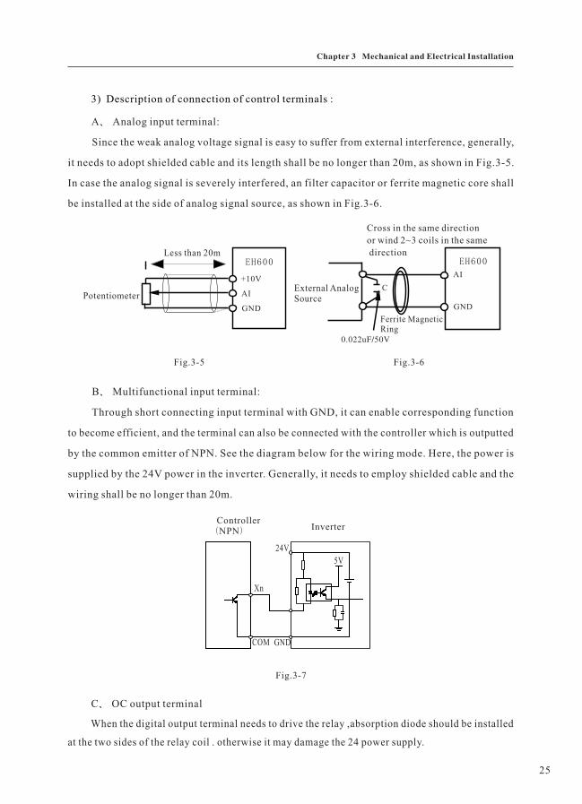
B Multifunctional input terminal:、
Through short connecting input terminal with GND, it can enable corresponding function
to become efficient, and the terminal can also be connected with the controller which is outputted
by the common emitter of NPN. See the diagram below for the wiring mode. Here, the power is
supplied by the 24V power in the inverter. Generally, it needs to employ shielded cable and the
wiring shall be no longer than 20m.
C OC output terminal、
A Analog input terminal:、
Since the weak analog voltage signal is easy to suffer from external interference, generally,
it needs to adopt shielded cable and its length shall be no longer than 20m, as shown in Fig.3-5.
In case the analog signal is severely interfered, an filter capacitor or ferrite magnetic core shall
be installed at the side of analog signal source, as shown in Fig.3-6.
3) Description of connection of control terminals :
When the digital output terminal needs to drive the relay ,absorption diode should be installed
at the two sides of the relay coil . otherwise it may damage the 24 power supply.
Less than 20m
External AnalogSource
Ferrite MagneticRing
Potentiometer
EH600 EH600
GND
AI
+10V
0.022uF/50V
Cross in the same direction
or wind 2~3 coils in the same
direction
GND
AI
C
Fig.3-5 Fig.3-6
ControllerNPN( ) Inverter
COM GND
24V
Xn
5V5V
Fig.3-7
25
Chapter 3 Mechanical and Electrical Installation

Caution : The absorption diode must be installed with correct polarity ,otherwise it may damage
the DC 24 power supply.
6、Solution to the EMC Matter
1 Harmonic effect、
1) The higher harmonics of power supply may damage the inverter . Thus, in some places where
mains quality is rather poor , it is recommended to install an AC input reactor.
2) As there is higher harmonics at the output side of the inverter , the capacitors and surge suppressor
which are used to improve the power may cause electrical oscillation to damage the equipment. Therefore ,
capacitor and surge suppressor can not be installed at the output side.
2 Electromagnetic interference and management、
1) There are two kinds of electromagnetic interference, one is interference to the inverter
caused by surrounding electromagnetic noise, this kind of interference may beget error action of
the inverter itself. However, the impact is small, internal management to this interference has
been done while designing the inverter, so the inverter has strong anti-interference capability.
Another is impact on peripheral equipment caused by the inverter.
Common approach:
A The grounding wires of the inverter and other electric products should be well grounded,、
the resistance shall be less than 5 .Ω
B、 The power cable and control line shall not be arranged in parallel, if it is allowable,
vertical arrangement shall be adopted.
C、 For high-demanded anti-interference places, it is recommended that shield cable shall
be employed to connect the inverter and the motor, moreover the shielding layer shall be grounded
reliably.
D、 For the equipment which has been interfered, it is recommended to employ twisted-pair
shielded control cables as the down-lead and the shielding layer shall be grounded reliably.
2) Handling method for the interference of the surrounding equipment on the inverter :
Generally, the reason why electromagnetic interference generated is that plenty of relays,
contactors and electromagnetic brakes are installed near the inverter. When the inverter has error
action due to the interferences, the following measures can be taken:
A、 Install an surge suppressor on the devices which generated interference.
B、 Install an filter at the input side of the inverter.
C、 Shield cable shall be employed as the down-lead of the control signal cable and the
detection line. Moreover, the shielding layer shall be grounded reliably.
26
Chapter 3 Mechanical and Electrical Installation

3) Handling method for the interference of inverter on the surrounding equipment :
There are two kinds of this interference: one is radiation interference of the inverter, and
another is radiation conducted by the down-lead which connects the inverter and the motor. These
two kinds of interference cause the surrounding electric equipment to suffer electromagnetic or
electrostatic induction, hereby, the equipment produces error action. For different interference,
different solutions are as follow:
A are generally weak. If they are、 The signal of measuring meters, receivers and sensors
placed nearby the inverter or together with the inverter in the same control cabinet, they are easy
to suffer interference and thus to generate error action. It is recommended to adopt the following
methods: keep it far away from the interference source, don’t arrange the signal cable with the
power cable in parallel and never bind them together, both the signal cable and power cable shall
employ shielded cable, install an linearity filter or wireless noise filter at the input/output side
of the inverter.
B、 When the interfered equipment and the inverter share the same power supply, an linearity
filter or wireless noise filter shall be installed between the inverter and the power supply in case
that the above methods cannot remove the interference.
C、 When the surrounding equipment is separately grounded, it can avoid the interference
caused by the leakage current of the grounding wire.
3 Leakage current and handling、
There are two kinds of leakage current when using the inverter. One is leakage current to
the earth, the other is leakage current between cables.
1) Factors influencing the leakage current to the earth and solutions:
There are distributed capacitance between lead cable and the earth, the larger the distributed
capacitance is, the larger the leakage current will be. The distributed capacitance can be reduced
by reducing the distance between the inverter and the motor, effectively. The higher the carrier
frequency is, the larger the leakage current will be. The leakage current can be reduced by reducing
the carrier frequency. However, reducing the carrier frequency may result in addition of motor
noise. Please pay attention to it! Installation of an reactor is also an effective method to remove
the leakage current.
The leakage current may increase along with the addition of circuit current. Therefore, if
the motor power is high, accordingly, the leakage current will be high too.
2) Factors influencing the leakage current between cables and solutions:
There is distributed capacitance between the output cables of the inverter. If the current,
which is passing through the circuitry, has high harmonic, it may cause resonance and thus to
27
Chapter 3 Mechanical and Electrical Installation

cause leakage current. Here, if thermal relay is being used, it may generate error action.
The solution is to reduce the carrier frequency or to install an output reactor. It is recommended
that while using the inverter, the electronic over current protection function can be employed
instead of installing a thermal relay in front of the motor.
28
Chapter 3 Mechanical and Electrical Installation

Chapter 4 Operation and Display
Chapter 4 Operation and Display
4.1 Introduction to operation and display interface
With the operation panel, it can perform such operations on the inverter as function parameter
modification, inverter working status monitoring and inverter running control(startup and stop).
Refer to Fig.4-1 for the physical appearance and function zone of the operation panel.
Fig 4 1 Operation panel diagram. -
Unit indicator
Function indicator
PotentiometerShift
Digital
display
Program
Exit
Data confirm
Enter
Run
Digital modification
Stop
ResetS key
S
ENTERFUNC
RUNSTOP
RESET
Optional purchse part
Digital
display
Program
Exit
Data confirm
Enter
Run
Digital modification
Stop
Reset
S key
Shift
Potentiometer
Function indicator
Unit indicator
29

RUN When it is ON , it indicates the inverter is in rotation status;
When it is OFF , it indicates the inverter is in stop status.
LOCAL/REMOT When it is OFF , it indicates the keyboard operation control status;
When it is ON , it indicates the terminal operation control status;
When it flashes , it indicates the communication control status;
When it is OFF , it indicates the inverter is in forward rotation status;
When it is ON , it indicates the inverter is in reverse rotation status.
FWD/REV
Hz refers to the unit of Frequency
A
Hz
A refers to the unit of Current
The digital LED of above displays function code , parameter numerical value , status parameter
and so on.
The digital LED of underside displays FV parameter which is set by F6.05 .
V refers to the unit of Voltage
1 Description of function LED indicator:、
2、 Unit indicator description:
3、Digital display zone :
4 Keyboard button description、
Button Name Function
FUNC Program key Entry and exit of primary menu
ENTER Confirmation key Enter the menu interfaces level by level, and confirm the set
parameters
Λ Increase key Increase of the data or function code
V Decrease key Decrease of the data or function code
>> Shift key Select the displayed parameters in turn on the stop display interface
and running display interface, select the modification digit of
parameters when modifying parameters.
RUN Running key It is used to start the running of the inverter under keyboard control
mode
STOP/RESET
Stop/Reset Press the button can stop the inverter from running while it is in
running status and reset the operation when it is in fault alarm status
30
Chapter 4 Operation and Display

4.2 Description of function code viewing and modification methods
Function CodeModification
Function CodeModification
Parameter SetModification
Data Display First-level Menu Second-level Menu Third-level Menu
Stop Display
Button Name Function
S S key F6.00=0 S key disabled
F6.00=1 Forward rotation jog operation (factory setting)
F6.00=2 Reverse rotation operation
F6.00=3 Clear the data of exact stop process
The operation panel of our inverter adopts three-level menu structure to carry out operations,
such as parameter setup.
The three-level menu includes function parameter set (level 1 menu)→function code(level→
2 menu) function code setup value(level 3 menu). Refer to Fig.4-2 for the operation procedure.→
FUNC
FUNC FUNC FUNC
ENTER ENTER
ENTER
50.00 F0 F0.08 50.00
Fig.4-2 Operation procedure of three-level menu
Caution: When operating on level 3 menu, press FUNC key or ENTER key to return to level
2 menu. The difference between FUNC key and ENTER key is described as follows: by pressing
ENTER key, it will save the setup parameter and return to the level 2 menu, then turn to the next
function code, automatically. While pressing FUNC key, it will return to level 2 menu, directly,
without saving the parameter, then return to the current function code.
Example: Modify the function code FB.02 from 10.00Hz to 15.00Hz. (The bold-faced word
indicates the flashing bit)
FUNC ENTER
FUNCFUNC ENTER
ENTER
50.00 F0 FB FB.00 FB.02
FB FB.03 1 .005 1 .000 10.00
ΛΛ
ΛΛ
ΛΛ
Λ Λ
Λ >>
Fig.4-3 Example of parameter editing operation
31
Chapter 4 Operation and Display

4.3 Method of viewing status parameter
4.4 Digital setting modify on-line
In the third menu, if the parameter has no flashing bit, it indicates that the function code
cannot be modified. The reasons could be:
1) The function code is an unchangeable parameter, such as actual detection parameter(FV
parameter), running record parameter, etc.
2) The function code cannot be modified in running status. It can be modified only after the
unit is stopped.
3) The operation panel is in code protection status.
The inverter provides 26 kinds of status parameter for user. There are two kinds of methods
to refer to.
1) As the FV status parameter can only be read, you can enter the three-level menu to view
it by using the same method to view others. Refer to 4.2 section for operation details. And it is
convenient to view parameters which don’t need to inquire again and again.
2) In stop or running status, the status parameter which needs requiring again and again is
setting by running parameter(F6.01 F6.02) and stop parameter( ) . The common~ F6.03 F6.04~
status parameter can be reached by controlling shift key( )to display in turns. Refer to parameter>>
group F6 for the setting methods.
Our company provide double-range LED operation panel which is optional. The content of
the under-range LED can be displayed by setting F6.05 to corresponding number of FV parameter.
It is convenient for client to debug. In respect that the interfaces of keyboard are unitive, users
can select the operation panel of double-range LED as the external keyboard of small power
inverter.
Set F6.01to F6.04 properly, press shift key( )to display those FV parameters that need to>>
be modified online. Refer to group F6 for the explanation.
1: Timely modification to the speed reference in open-loop running status
When one of parameter(F0.03 F0.04)is selected by frequency source to set as digital setting、
UP Then when it is switched to display status parameter FV.00 FV.01, FV.03、DOWN, 、 、FV.04,
FV.05、FV.06, you can modify the set frequency, the set rotate speed and the set line speed
on-line by pressing increase key and decrease key( ).ΛV
2: Timely modification to the PID digital reference in close-loop control status
When PID reference source selects PID digital reference, after switching to display status
parameter FV.13、FV.14, you can press increase key and decrease key( )to modify F9.02ΛV
on-line without entering the three-level menu.
32
Chapter 4 Operation and Display

4.6 Suggestive information
4.5 Password setting
3:Timely modification to correlative parameter of exact stop
When it is shifted to display status parameter FV.16 FV.21~ , you can press increase key and
decrease key( )to modify correlative parameter on-line without entering three-level menu.ΛV
Refer to the explanation of FA.11for the operation details about exact stop.
The inverter provides user password protection function. When F6.08 is set to non-zero
value, it indicates the user password, and the password protection turns valid after exiting the
function code editing status. When pressing FUNC key again, “0000”will be displayed to indicate
user to input password, the parameter cannot be modified until user password is input correctly.
Otherwise, all function codes cannot be modified, even if you entered the function code program
status.
To cancel the password protection function, enter with password and set F6.08 to “0”.
While operating the inverter, the operation panel provides full suggestive information.
P.LU: Suggest the insufficiency of voltage during the process of power-on and power-down.
CE: Owing to vibration or other casual factor, the keyboard communication may become
abnormal. You can retry the operation after raveling out those factors.
As for parameter that cannot be modified, there are suggestive information as follows:
RESE: parameter reserve, good for user’s expansion
HIDE: parameter hidden
E-CH: parameter cannot be modified(function parameter that cannot be modified when status
parameter or function parameter in running status).
33
Chapter 4 Operation and Display

Chapter 5 Function Parameter Table
Chapter 5 Function Parameter Table
According to different function, the function parameter of our inverter can be divided into
15 groups, there are F0 FD~ 、FV. Every function group contains some function codes, which
adopt the mark way that function code group number add function code number. The typeface
like FX.YZ means that the YZ function code in X group. For example, F6.08 means that the eighth
function code in the sixth group.
To convenient for the setting of function code, the function group corresponds to the level 1
menu, the function code corresponds to the level 2 menu, the function code parameternumber
corresponds to the level 3 menu while you are using the operation panel.
The description about the row content in the function table:
The first row“function code”: It refers to function parameter group and parameter number.
The second row“name”: It refers to the whole name of function parameter.
The third row“setup range”: It refers to valid setting value of function parameter.
The forth row“minimum unit”: It refers to the minimum unit of function parameter setup
value.
The fifth row“factory default value”: It refers to original setting value of function parameter
in factory.
The sixth row“modification”: It refers to the modifiable property(means whether it is
allowed to modify and the modifiable condition), the description is as follows:
“ ”: It indicates that the setup value of the parameter can be modified whether the○ inverter
is in stop status or running status.
“ ”: It indicates that the setup value of the parameter cannot be modified when the inverterΧ
is in running status.
“ ”: It indicates that the numerical value of the parameter is the actually measured value﹡
or reserves parameter, which cannot be modified.
In order to protect parameter more effectively, the inverter provides password protection
for function code. After setting user password(it means F6.08 parameter is set to non-zero), the
system will enter the status to confirm user password firstly when you press FUNC key to enter
the function code edit status, and then “0000”will be displayed to suggest you input password.
The parameter cannot be modified until user password is input correctly. Otherwise, all function
codes cannot be modified, even if you entered the function code program status.
34

In the unlock password protection status, you can change the user password at any moment,
the inverter takes the last input numerical value as the correct one.
If F6.08 is set to zero, you can cancel user password. If F6.08 is set to non-zero, then the
parameter is protected by password when upon power.
35
Chapter 5 Function Parameter Table

Function Parameter Table
Function
code
Name Setup range Minimum
unit
Factory
default value
Modifi-
cation
Group F0 Basic function group
F0 00. Software
version number
0~9999 1 Model
dependent*
F0 01. Control mode 0: V/F1: Reserved
1 0 Χ
F0 02. Command
source
selection
0: Operation panel running
command channel(LED ON)
1: Terminal command channel/
keyboard STOP disabled
(LED OFF)
2: Terminal command channel/
keyboard STOP enabled
(LED OFF)
3: Serial port command channel
/keyboard STOP disabled
(LED flashes)
4: Serial port command channel
/keyboard STOP enabled
(LED flashes)
1 0 ○
F0 03. Main
frequency
source X
selection
0: Panel potentiometer
1: Digital setup by UP and DW
adjustment(panel or external
terminal)
2: AI
3: Reserved
4: PULSE setup(DI)
5: MS speed
6: PLC
7: PID
8: Communication setup
1 0 ○
F0 04. Auxiliary
frequency
source Y
selection
0: Panel potentiometer
1: Digital setup by UP ans DW
adjustment(panel or external
terminal)
2: AI1
3: AI2
4: PULSE setup(DI)
5: MS speed
6: PLC
7: PID
8: Communication setup
1 2 ○
36
Chapter 5 Function Parameter Table

Function
code
Name Setup range Minimum
unit
Factory
default value
Modifi-
cation
F0 05. Auxiliary
frequency
source Y range
selection
0: Relative to
F0.11
1: Relative to frequency source
X
frequency upper
limit
1 0 ○
F0 06. Auxiliary
frequency
source Y range
0 100%~ 1% 100% ○
F0 07. Frequency
source
selection
0: Main frequency source X
1: Auxiliary frequency source
Y
2: Main frequency source X
plus auxiliary frequency
source Y
3: Switching between main
frequency source X and
auxiliary frequency source Y
4: Switching between main
frequency source X and(main
frequency source X plus
auxiliary frequency source Y
5: Switching between auxiliary
frequency source Y and(main
frequency source X plus
auxiliary frequency source Y
1 0 Χ
F0 08. Digital setup
UP and DW
adjustment
preset
frequency
0.0Hz frequency upper limit
F0.11(operation panel and
terminal UP and DW is enabled
~ 0.1Hz 50.0Hz ○
F0 09. Preset
frequency
control
0: Setup frequency saving when
power failure
1: Setup frequency without
saving when power failure
1 0 ○
F0 10. Running
direction
0: Direction is consistent
1: Direction is reverse
1 0 ○
F0 11. Frequency
upper limit
Lower limit F0.12 1500Hz~ 0.1Hz 50.0Hz ○
F0 12. Frequency
lower limit
0.0Hz upper limit F0.11~ 0.1Hz 0.5Hz ○
37
Chapter 5 Function Parameter Table

Function
code
Name Setup range Minimum
unit
Factory
default value
Modifi-
cation
F0 13. Speed-up time
1
0.1~6553.5s 0.1s Model
dependent
○
F0 14. Speed-down
time 1
0.1~6553.5s 0.1s Model
dependent
○
Group F1 Motor parameters
F1 00. Function
reserved
— — — *
F1.01 Rated power 0.2 1000.0kW(just for the user
to view)
~ 0.1kW Model
dependent
*
F1 02. Rated current 0.1 1000.0A(just for the user
to view)
~ 0.1A Model
dependent
*
F1 03. Rated voltage 1 250V
1 460V
~
~
1V 220V
380V
Χ
F1 04. Ratedfrequency
1.0H frequency upper limitz~ 0.1Hz 50.0Hz Χ
F1 05. Rated rotationspeed
0~9999rpm 1rpm 1460rpm ○
F1 06. Motor typeselection
0: common asynchronous motor
1 reserved
2: reserved
:
1 0 Χ
F1 07. Motor no-loadcurrentcoefficient
10% 90%~ 1.0% 40.0% Χ
Group F2 V/F control parameters
F2 00. V/F curvesetup
0: straight V/F curve
1 multiple-point V/F curve
2: square V/F curve 1(1.5 time
power
3: square V/F curve 2(2.0 time
power
:
1 0 Χ
F2 01. V/F frequencypoint F1
0.00Hz F2~ 0.1Hz 0.0Hz Χ
F2 02. V/F voltagepoint V1
0.0% V2~ 0.1% 0.0% Χ
38
Chapter 5 Function Parameter Table
Function
code
Name Setup range Minimum
unit
Factory
default value
Modifi-
cation
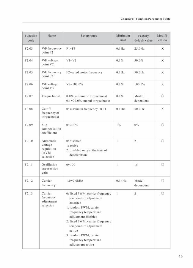
F2.03 V/F frequencypoint F2
F1~F3 0.1Hz 25.0Hz Χ
F2.04 V/F voltagepoint V2
V1~V3 0.1% 50.0% Χ
F2.05 V/F frequencypoint F3
F2~rated motor frequency 0.1Hz 50.0Hz Χ
F2.06 V/F voltagepoint V3
V2~100.0% 0.1% 100.0% Χ
F2.07 Torque boost 0.0%: automatic torque boost
0.1 20.0%: manul torque boost~
0.1% Model
dependent
○
F2.08 Cutofffrequency oftorque boost
0 maximun frequency F0.11~ 0.1Hz 50.0Hz Χ
F2.09 Slipcompensationcoefficient
0 200%~ 1% 0% ○
F2.10 Automaticvoltageregulation(AVR)selection
0: disabled
1: active
2: disabled only at the time of
deceleration
1 2 ○
F2.11 Oscillationsuppressiongain
0 100~ 1 15 ○
F2.12 Carrier
frequency
1.0 9.0kHz~ 0.1kHz Model
dependent
○
F2.13 Carrierfrequencyadjustmentselection
0: fixed PWM, carrier frequency
temperature adjustment
disabled
1: random PWM, carrier
frequency temperature
adjustment disabled
2: fixed PWM, carrier frequency
temperature adjustment
active
3: random PWM, carrier
frequency temperature
adjustment active
1 2 ○
39
Chapter 5 Function Parameter Table

Function
code
Name Setup range Minimum
unit
Factory
default value
Modifi-
cation
Group F3 Input terminal
F3 00. X1 terminal
function
selection
(0 30)~
0: No function
1: MS speed terminal 1
2: MS speed terminal 2
3: MS speed terminal 3
4: MS speed terminal 4
5: Three-line mode running
control
6: Forward rotation jog(JOGF)
7: Reserve rotation jog(JOGR)
8: Terminal UP
9: Terminal DOWN
10: Coast to stop
11:Pause
12:External fault normally open
input
13: Acceleration/deceleration
selection terminal 1
14: Acceleration/deceleration
selection terminal 2
15: Frequency source switching
16: UP and DOWN setup clear
(terminal and operation panel)
17: DC brake input command
DB of stop
18: Acceleration/deceleration
disabled
19: PID pause
20: PLC status reset
21: Swing frequency pause
22: Counter reset
23: Length reset
24: Time reset
25: PID second reference value
enable switching terminal
26: Forward rotation(FWD)
27: Reserve rotation(REV)
28: Fault reset(RST)
29: Broken wire reset terminal
30: Broken wire proximity
switch input
31: Counter input
32: Length count input
1 26 Χ
F3.01 X2 terminal
function
selection
(0 30)~
1 6 Χ
F3 02. X3 terminal
function
selection
(0 30)~
1 28 Χ
F3 03. X4 terminal
function
selection
(0 30)~
1 0 Χ
F3 04. X5 terminal
function
selection
(0 32)~
1 0 Χ
F3 05. Functionreserved
1 0 *
F3 06. Terminalcommandmode
0: Two-line mode 1
1 Two-line mode 2
2: Three-line mode 1
3: Three-line mode 2
:
1 0 Χ
40
Chapter 5 Function Parameter Table

Function
code
Name Setup range Minimum
unit
Factory
default value
Modifi-
cation
F3.07 Change rate of
terminals
UP/DW
0.01~100.0Hz/s 0.01Hz 1.00Hz/s ○
F3.08 AI minimum
input
0.00V~10.00V when current
inputs: 1V corresponds to 2mA
0.01V 0.00V ○
F3.09 AI minimum
input
corresponding
setup
-100.0~100.0% 0.1% 0.0% ○
F3.10 AI maximum
input
0.00V~10.00V when current
inputs: 1V corresponds to 2mA
0.01V 10.00V ○
F3.11 AI maximum
input
corresponding
setup
-100.0~100.0% 0.1% 100.0% ○
F3.12 Function
reserved
— — *
F3.13 Function
reserved
— — *
F3.14 Function
reserved
— — *
F3.15 Function
reserved
— — *
F3.16 Pulse input
(DI)lower limit
frequency
0.000kHz~F3.18 0.001kHz 0.0kHz ○
F3.17 Pulse input
(DI) lower
limit frequency
corresponding
setup
-100.0~100.0% 0.1% 0.0% ○
F3.18 Pulse input
(DI)upper limit
frequency
F3.16~10.00kHz 0.001kHz 10.00kHz ○
41
Chapter 5 Function Parameter Table

Function
code
Name Setup range Minimum
unit
Factory
default value
Modifi-
cation
F3.19 Pulse input
(DI) upper
limit frequency
corresponding
setup
-100.0~100.0% 0.1% 100.0% ○
F3.20 Analog input
filter time
0.01~10.00s 0.01s 0.25s ○
Group F4 Output terminal
F4 00. Relay output
selection
0: No output
1: Inverter is running
2: Fault output
3: Frequency level detection
FDT1 output
4: Frequency level detection
FDT2 output
5: Frequency arrival
6: In the zero speed operation
7: Inverter overload
pre-warning
8: Setup counting value arrival
9: Designated counting value
arrival
10: Setup length arrival
11: PLC circulation completion
12: PLC phase completion
13: Setup running time arrival
14: Output frequency arrive at
upper limit
15: Output frequency arrive at
lower limit
16: Output X1
17: Output X2
18: Running command
indication
19: Reserved
20: Dormant
21: Ready to running
22: Three-line running mode 1
start to trigger information
output by itself
1 2 ○
F4.01 OC output
selection
1 1 ○
F4 02. Function
reserved
1 0 *
F4 03. Function
reserved
1 0 *
42
Chapter 5 Function Parameter Table

Function
code
Name Setup range Minimum
unit
Factory
default value
Modifi-
cation
23: Band-type brake
information output
24: Broken wire detection
output
25: Reference length arrival
F4 04. OC close
protract
0~1000.0s 0.1s 0.0s ○
F4 05. OC brake
protract
0~1000.0s 0.1s 0.0s ○
F4 06. Function
reserved
— — *
F4 07. Function
reserved
— — *
F4 08. AO output
channel
selection
0: 0 10V
1: 2 10V
~
~
1 0 ○
F4 09. AO output gain 1.0 500.0%~ 0.1% 100% ○
F4.10 Function
reserved
— — — *
F4.11 AO output
selection
0: Running frequency
1: Setup frequency
2: Output current
3: Output voltage
4: Pulse reference(DI)
5: AI
6: Reserved
7: Length
8: Counting value
9: Running time
10: Output torque
11: Output power
12: Keyboard potentiometer
reference
0 0 ○
43
Chapter 5 Function Parameter Table

Function
code
Name Setup range Minimum
unit
Factory
default value
Modifi-
cation
Group F5 Start/stop control
F5 00. Start mode 0: Start from start frequency
1 Perform braking prior to start
2: Velocity tracking restart
:
0 0 ○
F5.01 Startfrequency
0.0Hz 10.0Hz~ 0.1Hz 0.5Hz ○
F5 02. Startfrequencyholding time
0.0 36.0s~ 0.1s 0.0s Χ
F5 03. DC brakecurrent at start
0 100%~ 1% 0% Χ
F5 04. DC brake timeat start
0.0 36.0s~ 0.1s 0.0s Χ
F5 05. Stop mode 0: Decelerate to stop
1 Coast to stop:
1 0 ○
F5 06. DC brakebeginningfrequency atstop
0.0Hz frequency upper limit
F0.11
~ 0.1Hz 0.0Hz ○
F5 07. DC brakewaiting time atstop
0.0 36.0s~ 0.1s 0.0s Χ
F5.08 DC brakecurrent at stop
0 100%~ 1% 0% Χ
F5.09 DC brake timeat stop
0.0 36.0s~ 0.1s 0.0s Χ
F5.10 Beginningvoltage ofdynamicbraking
115 140%~ 1V 130% ○
F5.11 Use ratio ofdynamicbraking
0 100%~ 1% 30% ○
F5.12 Acceleration/decelerationmode
0: Straight acceleration/
deceleration
1 S-curve acceleration/
deceleration
:
1 0 Χ
44
Chapter 5 Function Parameter Table

Function
code
Name Setup range Minimum
unit
Factory
default value
Modifi-
cation
F5 13. Start segment
proportion of
S-curve
0.0~40.0% 0.1% 30.0% Χ
F0 14. End segment
proportion of
S-curve
0.0~40.0% 0.1% 30.0% Χ
Group F6 Keyboard and display
F6 00. S key function
selection
0: S key function disabled
1 Forward rotation jog
command
2: Reverse rotation run
command
3: Clear the data of exact stop
process
:
1 1 ○
F6.01 LED operation
display
parameter 1
0 8191~ 1 5 ○
F6 02. LED operation
display
parameter 2
0 8191~ 1 0 ○
F6 03. LED stop
display
parameter 1
0 8191~ 1 1 ○
F6 04. LED stop
display
parameter 12
0 8191~ 1 0 ○
F6 05. Auxiliarysupervise itemselection
0~25 1 1 ○
F6 06. Load speeddisplaycoefficient
0.01 100.0~ 0.01 1.00 ○
F6 07. Functionreserved
— — — *
45
Chapter 5 Function Parameter Table

Function
code
Name Setup range Minimum
unit
Factory
default value
Modifi-
cation
F6.08 User password 0~9999 1 0 ○
F6.09 Copy keyboard
function
selection
Please refer to the copy
keyboard description of our
company
1 0 ○
Group F7 Auxiliary function
F7 00. Jog running
frequency
0.0Hz frequency upper limit
F0.11
~ 0.1Hz 5.0Hz ○
F7.01 Jog
acceleration
time
0.0 6553.5s~ 0.1s 20.0s ○
F7 02. Jog
deceleration
time
0.0 6553.5s~ 0.1s 20.0s ○
F7 03. Jog action
selection on
running status
0: Active
1 Disabled
It can avoid the inverter
accepting error operation to
cause jog command by setting 1
:
1 0 ○
F7 04. Acceleration
time 2
0.1 6553.5s~ 0.1s 20.0s ○
F7 05. Decelerationtime 2
0.1 6553.5s~ 0.1s 20.0s ○
F7 06. Acceleration
time 3
0.1 6553.5s~ 0.1s 20.0s ○
F7 07. Decelerationtime 3
0.1 6553.5s~ 0.1s 20.0s ○
F7 08. Acceleration
time 4
0.1 6553.5s~ 0.1s 20.0s ○
F7 09. Decelerationtime 4
0.1 6553.5s~ 0.1s 20.0s ○
F7.10 Skip frequency 0.0Hz frequency upper limit
F0.11
~ 0.1Hz 0.0Hz ○
F7.11 Skip frequencyamplitude
0.0Hz frequency upper limit
F0.11
~ 0.1Hz 0.0Hz ○
46
Chapter 5 Function Parameter Table

Function
code
Name Setup range Minimum
unit
Factory
default value
Modifi-
cation
F7.12 Forward/
reverse
rotation dead-
zone time
0.0~3000.0s 0.1s 0.0s Χ
F7.13 Reverse
control
0: Active
1: Disabled
1 0 Χ
F7.14 Setup
frequency
lower than
frequency
lower limit
action
0: Run with frequency lower
limit
1: Stop
2: Zero speed operation
1 1 Χ
F7.15 Frequency
detection
value (FDT
1level)
0.0Hz frequency upper limit
F0.11
~ 0.1Hz 50.0Hz ○
F7.16 Frequency
detection
hysteresis
(FDT1
hysteresis )
0.0Hz frequency upper limit
F0.11
~ 0.1Hz 2.0Hz ○
F7.17 Frequency
detection
value (FDT 2
level)
0.0Hz frequency upper limit
F0.11
~ 0.1Hz 50.0Hz ○
F7.18 Frequency
detection
hysteresis
(FDT1
hysteresis )
0.0Hz frequency upper limit
F0.11
~ 0.1Hz 2.0Hz ○
F7.19 Frequency
arrival
detection
amplitude
0.0Hz frequency upper limit
F0.11
~ 0.1Hz 2.0Hz ○
47
Chapter 5 Function Parameter Table
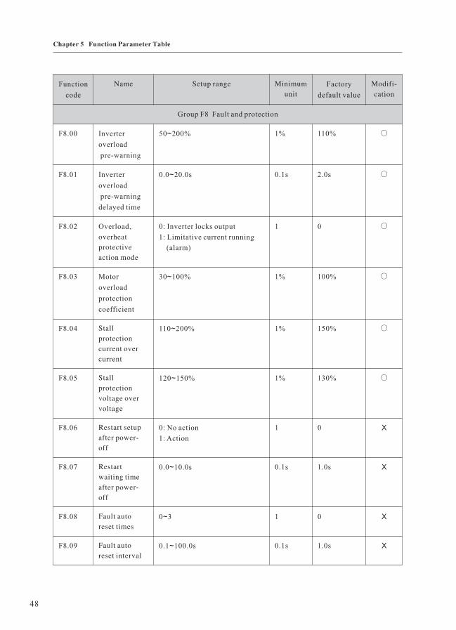
Function
code
Name Setup range Minimum
unit
Factory
default value
Modifi-
cation
Group F8 Fault and protection
F8 00. Inverter
overload
pre-warning
50 200%~ 1% 110% ○
F8.01 Inverter
overload
pre-warning
delayed time
0.0 20.0s~ 0.1s 2.0s ○
F8 02. Overload、
overheat
protective
action mode
0: Inverter locks output
1: Limitative current running
(alarm)
1 0 ○
F8 03. Motor
overload
protection
coefficient
30 100%~ 1% 100% ○
F8 04. Stall
protection
current over
current
110 200%~ 1% 150% ○
F8 05. Stall
protection
voltage over
voltage
120 150%~ 1% 130% ○
F8 06. Restart setup
after power-
off
0: No action
1: Action
1 0 Χ
F8 07. Restart
waiting time
after power-
off
0.0 10.0s~ 0.1s 1.0s Χ
F8 08. Fault auto
reset times
0 3~ 1 0 Χ
F8 09. Fault auto
reset interval
0.1 100.0s~ 0.1s 1.0s Χ
48
Chapter 5 Function Parameter Table

Function
code
Name Setup range Minimum
unit
Factory
default value
Modifi-
cation
F8.10 The first fault
type
0: No fault(--)
1: Inverter unit protection(E.1)
2: Acceleration over current
(E.OC1)
3: Deceleration over current
(E.OC2)
4: Constant speed over current
(E.OC3)
5: Acceleration over voltage
(E.OU1)
6: Deceleration over voltage
(E.OU2)
7: Constant speed over voltage
(E.OU3)
8: Stop over voltage(E.OU4)
9: Running under voltage
(E.LU)
10: Inverter overload(E.OL1)
11: Motor overload(E.OL2)
12: Output phase failure(E.LF)
13: Inverter overheat(E.OH)
14: External equipment fault
(E.EF)
15: Communication fault
(E.CE)
16: Output grounding(E.GF)
17: CPU interference(E.2)
18: Current detection fault
(E.3)
19: EEPROM read-write fault
(E.4)
20: Input phase failure(E.5)
21: PID feedback disconnection
(E.6)
22: Reserved
— — *
F8.11 The second
fault type
— — *
F8.12 The third fault
type
— — *
F8.13 Output
frequency
upon fault
— 0.1Hz — *
F8.14 Output current
upon fault
— 0.1A — *
49
Chapter 5 Function Parameter Table

Function
code
Name Setup range Minimum
unit
Factory
default value
Modifi-
cation
F8.15 Bus voltage
upon fault
— 1V — *
F8.16 Module
temperature
upon fault
— 0.1℃ — *
F8.17 Terminal state
upon fault
— 1 — *
Group F9 PID function
F9 00. PID control
mode setup
The third part of LED: PID
action direction
0: positive action
1 reverse action
The second part of LED: PID
feedback source
0: AI
1 5: reserved
6: pulse setup(DI)
7:communication setup
The first part of LED: PID
reference source
0: panel potentiometer
1: PID digital reference
(F9.02)
2: AI
3: reserved
4: pulse setup(DI)
5:communication setup
:
~
1 001 Χ
F9.01 PID reference
feedback range
0 9999~ 1 1000 ○
F9 02. PID digital
reference
0 F9.01~ 1 500 ○
F9 03. PID second
digital
reference
0 F9.01
note: It can switch with other
PID reference source by setting
the external terminal to 25.
~ 1 500 ○
F9 04. Deviation
limit
0.0 50.0%~ 0.1% 0.0% ○
50
Chapter 5 Function Parameter Table

Function
code
Name Setup range Minimum
unit
Factory
default value
Modifi-
cation
F9 05. Function
reserved
— — — *
F9.06 Proportional
gain P
0.0 100.0%
0.0%: close P
~ 1 20.0% ○
F9 07. Integration
time I
0.1 100.0s
100.0s: close I
~ 0.1s 2.0s ○
F9 08. Differential
time D
0.0 10.00s
0.0s: close D
~ 0.01s 0.0s ○
F9 09. Differential
amplitude
0.0 100.0%~ 0.1% 5.0% ○
F9.10 PID preset
frequency
0.0Hz frequency upper limit~ 0.1Hz 0.0Hz ○
F9.11 PID preset
frequency
holding time
0.0 3600.0s~ 0.1s 0.0s Χ
F9.12 Dormant
frequency
0.0Hz frequency upper limit~ 0.1Hz 0.0Hz ○
F9.13 Dormant
protract
0.0 3600s~ 0.1s 60.0s ○
F9.14 Awakening
threshold
0.0 100.0%~ 0.1% 0.0% ○
F9.15 Awakening
protract
0.0 60.0s~ 0.1s 0.5s ○
F9.16 PID feedback
disconnection
detection
The second part of LED: action
mode
0: enter the PID feedback
disconnection fault state
(display E.6)
1: stop in terms of the stop
mode of F5.05
2: keep current running
frequency
1 00 Χ
51
Chapter 5 Function Parameter Table

Function
code
Name Setup range Minimum
unit
Factory
default value
Modifi-
cation
The first part of LED: detection
mode
0: no detection
1: detection in terms of PID
feedback signal
2: detection in terms of
disconnection proximity switch
signal
F9.17 PID feedback
disconnection
result
0.0~50.0% 0.1% 0.0% ○
F9.18 PID feedback
disconnection
and judgement
protract
0~20.0s 0.1s 2.0s ○
F9.19 Function
reserved
— — — *
F9.20 Function
reserved
— — — *
F9.21 Function
reserved
— — — *
F9.22 The precision
after PID range
radix point
0~3 1 0 ○
Group FA Swing frequency, fixed length, count and timing
FA.00 Swing setup
mode
The second part of LED: swing
frequency function enable
0: disable
1: enabled
The first part of LED: swing
amplitude benchmark
0: no detection
1: relative to the central
frequency
2: relative to frequency upper
limit
1 00 Χ
52
Chapter 5 Function Parameter Table

Function
code
Name Setup range Minimum
unit
Factory
default value
Modifi-
cation
FA.01 Swing
frequency
amplitude
0.0 100.0%~ 0.1% 0.0% ○
FA.02 Kick
frequency
amplitude
0.0 50.0%~ 0.1% 0.0% ○
FA.03 Swing
frequency
cycle
0.1 3000.0s~ 0.1s 10.0s ○
FA.04 Time constant
of triangular
wave boost
0.1 100.0%~ 0.1% 50.0% ○
FA.05 Setup length 0.0 65.535(km)~ 0.001km 1.000km ○
FA.06 Designed
length
0.0 65.535(km)~ 0.001km 1.000km ○
FA.07 Number of
pulses each
meter
0.1 6553.5~ 0.1 100.0 ○
FA.08 Setup counting
value
1 9999~ 1 1000 ○
FA.09 Designed
counting value
1 9999~ 1 1000 ○
FA.10 Internal timing
setup running
time
0.0 65.535h~ 0.001h 24.000h ○
FA.11 Exact stop
mode setup
0: disabled
1: setup counting value arrival
2: setup length arrival
3: setup running time arrival
1 0 Χ
53
Chapter 5 Function Parameter Table

Function
code
Name Setup range Minimum
unit
Factory
default value
Modifi-
cation
Group FB MS speed and PLC
FB 00. MS speed 0 0.0Hz frequency upper limit~ 0.01Hz 0.0Hz ○
FB 01. MS speed 1 0.0Hz frequency upper limit~ 0.01Hz 0.0Hz ○
FB 02. MS speed 2 0.0Hz frequency upper limit~ 0.01Hz 0.0Hz ○
FB 03. MS speed 3 0.0Hz frequency upper limit~ 0.01Hz 0.0Hz ○
FB 04. MS speed 4 0.0Hz frequency upper limit~ 0.01Hz 0.0Hz ○
FB 05. MS speed 5 0.0Hz frequency upper limit~ 0.01Hz 0.0Hz ○
FB 06. MS speed 6 0.0Hz frequency upper limit~ 0.01Hz 0.0Hz ○
FB 07. MS speed 7 0.0Hz frequency upper limit~ 0.01Hz 0.0Hz ○
FB 08. MS speed 8 0.0Hz frequency upper limit~ 0.01Hz 0.0Hz ○
FB 09. MS speed 9 0.0Hz frequency upper limit~ 0.01Hz 0.0Hz ○
FB 10. MS speed 10 0.0Hz frequency upper limit~ 0.01Hz 0.0Hz ○
FB 11. MS speed 11 0.0Hz frequency upper limit~ 0.01Hz 0.0Hz ○
FB 12. MS speed 12 0.0Hz frequency upper limit~ 0.01Hz 0.0Hz ○
FB 13. MS speed 13 0.0Hz frequency upper limit~ 0.01Hz 0.0Hz ○
FB 14. MS speed 14 0.0Hz frequency upper limit~ 0.01Hz 0.0Hz ○
FB 15. MS speed 15 0.0Hz frequency upper limit~ 0.01Hz 0.0Hz ○
FB 16. PLC running
mode
The second part of LED: PLC
running time unit selection
0: second
1: hour
The first part of LED: PLC
action mode
0: stop upon completion of
one-time running
1: keep final value upon
completion of one-time running
2: constant circulation
1 00 Χ
54
Chapter 5 Function Parameter Table

Function
code
Name Setup range Minimum
unit
Factory
default value
Modifi-
cation
FB.17 PLC power
failure
recorded
selection
0: power failure non-recorded
1: power failure recorded
0 0 ○
FB.18 Running time
of zero-
segment
0.0 6553.5s(h)~ 0.1s(h) 0.0s ○
FB.19 Running time
of first-
segment
0.0 6553.5s(h)~ 0.1s(h) 0.0s ○
FB.20 Running mode
of zero and
first-segment
The forth part of LED:
acceleration/deceleration time
selection of 1 segment:0 3
The third part of LED:
direction selection of 1segment:
0: forward 1: reverse
The second part of LED:
acceleration/deceleration time
selection of 0 segment:0 3
The first part of LED: direction
selection of 0 segment:
0: forward 1: reverse
~
~
1 0000 ○
FB.21 Running time
of second-
segment
0.0 6553.5s(h)~ 0.1s(h) 0.0s ○
FB.22 Running time
of third-
segment
0.0 6553.5s(h)~ 0.1s(h) 0.0s ○
55
Chapter 5 Function Parameter Table

Function
code
Name Setup range Minimum
unit
Factory
default value
Modifi-
cation
FB.23 Running mode
of second and
third-segment
The forth part of LED:
acceleration/deceleration time
selection of 3 segment:0 3
The third part of LED:
direction selection of 3segment:
0: forward 1: reverse
The second part of LED:
acceleration/deceleration time
selection of 2 segment:0 3
The first part of LED: direction
selection of 2 segment:
0: forward 1: reverse
~
~
1 0000 ○
FB.24 Running time
of forth-
segment
0.0 6553.5s(h)~ 0.1s(h) 0.0s ○
FB.25 Running time
of fifth-
segment
0.0 6553.5s(h)~ 0.1s(h) 0.0s ○
FB.26 Running mode
of forth and
fifth-segment
The forth part of LED:
acceleration/deceleration time
selection of 5 segment:0 3
The third part of LED:
direction selection of 5segment:
0: forward 1: reverse
The second part of LED:
acceleration/deceleration time
selection of 4 segment:0 3
The first part of LED: direction
selection of 4 segment:
0: forward 1: reverse
~
~
1 0000 ○
FB.27 Running time
of sixth-
segment
0.0 6553.5s(h)~ 0.1s(h) 0.0s ○
FB.28 Running time
of seventh-
segment
0.0 6553.5s(h)~ 0.1s(h) 0.0s ○
56
Chapter 5 Function Parameter Table

Function
code
Name Setup range Minimum
unit
Factory
default value
Modifi-
cation
FB.29 Running mode
of sixth and
seventh-
segment
The forth part of LED:
acceleration/deceleration time
selection of 7 segment:0 3
The third part of LED:
direction selection of 7segment:
0: forward 1: reverse
The second part of LED:
acceleration/deceleration time
selection of 6 segment:0 3
The first part of LED: direction
selection of 6 segment:
0: forward 1: reverse
~
~
1 0000 ○
FB.30 Running time
of eighth-
segment
0.0 6553.5s(h)~ 0.1s(h) 0.0s ○
FB.31 Running time
of ninth-
segment
0.0 6553.5s(h)~ 0.1s(h) 0.0s ○
FB.32 Running mode
of eighth and
ninth-segment
The forth part of LED:
acceleration/deceleration time
selection of 9 segment:0 3
The third part of LED:
direction selection of 9segment:
0: forward 1: reverse
The second part of LED:
acceleration/deceleration time
selection of 8 segment:0 3
The first part of LED: direction
selection of 8 segment:
0: forward 1: reverse
~
~
1 0000 ○
FB.33 Running time
of tenth-
segment
0.0 6553.5s(h)~ 0.1s(h) 0.0s ○
FB.34 Running time
of eleventh-
segment
0.0 6553.5s(h)~ 0.1s(h) 0.0s ○
57
Chapter 5 Function Parameter Table

Function
code
Name Setup range Minimum
unit
Factory
default value
Modifi-
cation
FB.35 Running mode
of tenth and
eleventh-
segment
The forth part of LED:
acceleration/deceleration time
selection of 11 segment:0 3
The third part of LED:
direction selection of
11segment:
0: forward 1: reverse
The second part of LED:
acceleration/deceleration time
selection of 10 segment:0 3
The first part of LED: direction
selection of 10 segment:
0: forward 1: reverse
~
~
1 0000 ○
FB.36 Running time
of twelfth-
segment
0.0 6553.5s(h)~ 0.1s(h) 0.0s ○
FB.37 Running time
of thirteenth-
segment
0.0 6553.5s(h)~ 0.1s(h) 0.0s ○
FB.38 Running mode
of twelfth and
thirteenth-
segment
The forth part of LED:
acceleration/deceleration time
selection of 13 segment:0 3
The third part of LED:
direction selection of
13segment:
0: forward 1: reverse
The second part of LED:
acceleration/deceleration time
selection of 12 segment:0 3
The first part of LED: direction
selection of 12 segment:
0: forward 1: reverse
~
~
1 0000 ○
FB.39 Running time
of fourteenth-
segment
0.0 6553.5s(h)~ 0.1s(h) 0.0s ○
58
Chapter 5 Function Parameter Table

Function
code
Name Setup range Minimum
unit
Factory
default value
Modifi-
cation
FB.40 Running time
of fifteenth-
segment
0.0 6553.5s(h)~ 0.1s(h) 0.0s ○
FB.41 Running mode
of fourteenth
and fifteenth-
segment
The forth part of LED:
acceleration/deceleration time
selection of 15 segment:0 3
The third part of LED:
direction selection of
15segment:
0: forward 1: reverse
The second part of LED:
acceleration/deceleration time
selection of 14 segment:0 3
The first part of LED: direction
selection of 14 segment:
0: forward 1: reverse
~
~
1 0000 ○
Group FC Communication parameters
FC.00 Baud rate 0: 1200BPS
1: 2400BPS
2: 4800BPS
3: 9600BPS
4: 19200BPS
5: 38400BPS
1 3 ○
FC.01 Data format The second part of LED: data
frames check mode selection
0: CRC16
1: accumulate sum(16 bit)
The first part of LED: byte
check mode selection
0: no parity check(8,N,2)
note: two stop bit
1: even parity check(8,E,1)
note: one stop bit
2: odd parity check(8,0,1)
note: one stop bit
1 00 ○
59
Chapter 5 Function Parameter Table

Function
code
Name Setup range Minimum
unit
Factory
default value
Modifi-
cation
FC.02 Local
address
0 247
0: broadcast address When local
address is zero, it indicates that
the local computer as host sends
synchronous command and
frequency signal to all guests
with broadcast address. The
guests accept the command and
execute it in terms of
correspondence of the baud rate
and data format.
1 247: slave address
~
~
1 1 ○
FC.03 Response
delay
0 20ms~ 1ms 2ms ○
FC.04 Communica-
tion overtime
time
0.0(inactive), 0.1 60.0s~ 0.1s 0.0s ○
FC.05 Communica-
tion overtime
action
selection
0: Stop
1: Keep current setup frequency
2: Stop and notify communication
fault(E.CE)
1 0 ○
Group FD Particular function
FD.00 Droop
control
0.0Hz 10.0Hz~ 0.1Hz 0.0Hz ○
FD.01 Function
reserved
— — — *
FD.02 Function
reserved
— — — *
FD.03 Relay break
protract
0 1000.0s~ 0.1s 0.0s ○
FD.04 Pulse input
(DI) filter
0 10~ 1 4 ○
FD.05 Function
reserved
— — — *
60
Chapter 5 Function Parameter Table

Function
code
Name Setup range Minimum
unit
Factory
default value
Modifi-
cation
FD.06 Output phase
failure
protection
selection
0 disabled
1: active
: 1 1 ○
FD.07 Response
delay
— — — *
FD.08 Inner fan
control
0 automatic
1: constant open
: 1 0 ○
FD.09 User
password
0 9999~ 1 0 Χ
FD.10 Parameter
initialization
0 no operation
1: restore factory default setup
value
2: clear the fault record
: 1 0 Χ
Group FV Status parameters
FV.00 Output
frequency
0.0Hz frequency upper limit~ 0.1Hz — *
FV.01 Setup
frequency
(flashes)
0.0Hz frequency upper limit~ 0.1Hz — *
FV.02 Output
current
0.1 1000.0A~ 0.01A — *
FV.03 Running
rotation
speed
0 9999rpm~ 1r/min — *
FV.04 Setup
rotation
speed
(flashes)
0 9999rpm~ 1r/min — *
FV.05 Running load
speed
0.001 9999~ 0.01m/s — *
FV.06 Setup load
speed
(flashes)
0.001 9999~ 0.01m/s — *
61
Chapter 5 Function Parameter Table

Function
code
Name Setup range Minimum
unit
Factory
default value
Modifi-
cation
FV.07 Output
voltage
0 rated voltage~ 1V — *
FV.08 Bus voltage — 1V — *
FV.09 Input AC
voltage
— 1V — *
FV.10 AI 0 10.00V Note: when current
inputs: 1V corresponds to 2mA
~ 0.01V — *
FV.11 Function
reserved
— *
FV.12 Pulse
reference
(DI)
0 10.00kHz~ 0.001kHz — *
FV.13 PID setup
(flashes)
— 0.1% — *
FV.14 PID
feedback
— 0.1% — *
FV.15 Terminal
status
Refer to the following detailed
explanation
— — *
FV.16 Actual
counting
value
0 setup counting value~ 1 0 ○
FV.17 Setup
counting
value
(flashes)
1 9999~ 1 1000 ○
FV.18 Actual
length
0.0 65.535km~ 0.001km 0.0km ○
FV.19 Setup length
(flashes)
0.0 65.535km~ 0.001km 1.000km ○
FV.20 Actual
running time
0.0 65.535h~ 0.001h — ○
FV.21 Setup
running time
(flashes)
0.0 65.535h~ 0.001h 24.00h ○
62
Chapter 5 Function Parameter Table

Function
code
Name Setup range Minimum
unit
Factory
default value
Modifi-
cation
FV.22 AO output — *
FV.23 Function
reserved
— *
FV.24 Radiator
temperature
— 0.1℃ — *
FV.25 Total
running time
Total running time after leave
factory
1h — *
Display mode of terminal status parameter (FV.15/F8.16)
The displayed terminal information contains multi-functional terminal X1 to X7, double direction
open collector output terminal OC and relay output terminal state. The state of each function terminal
was indicated by ON or OFF of certain segment, the terminal state is enabled when it is ON,
contrarily, the terminal is in disabled state.
As shown in following figure: The input of multi-functional terminal X1 X2 X4 X5 and
is enabled, others are disabled. There are four constant ON segment for observe
expediently.
、 、 、
LED digital
the
output of OC relay、
Constant ON segment
for expediently observing
Relay
Terminal status indication
X5X4X3
OC
X2X1 X6 X7
63
Chapter 5 Function Parameter Table

Chapter 6 Parameter Description
Group F0 Basic Function
Chapter 6 Parameter Description
F0.00 Software version number Factory default value Model dependent
Setup range Display the software version of the machine
F0.01 Control mode Factory default value 0
Setup range 0 V/F control
1 Reserved
F0.02 Command source selection Factory default value 0
Setup range 0 Operation panel running command channel (LED ON)
1 Terminal command channel/keyboard STOP disabled (LED OFF)
2 Terminal command channel/keyboard STOP enabled (LED OFF)
3 Serial port command channel/keyboard STOP disabled (LED flashes)
4 Serial port command channel/keyboard STOP enabled (LED flashes)
Select the channel for inverter control command:
The inverter control command includes start, stop, forward rotation, reverse rotation and
jog.
0: Operation panel command channel
Perform running command control with keys on the operation panel, such as RUN STOP、 、
S key.
1(2): Terminal command channel
Perform running command controlled by the multifunctional input terminals, such as FWD、
REV JOGF JOGR, etc.、 、
3(4): Serial port command channel
The running command is sent by the host computer via the communication mode. When
selecting this item, it must be used together with Modbus of Shenzhen XILIN ELECTRIC
TECHNOLOGIES CO., LTD.
64

When the parameter is set to 2/4(STOP enabled), you can stop the inverter by pressing STOP
key on the operation panel. To restart it, firstly, you must use the multifunctional input terminal/
Modbus interface to input stop command, and then input running command.
As for the detailed setup method of terminal command and the explanation about Modbus
communication command, please refer to the parameter explanation in F3.06 and <<EH600 serial
communication protocol>>, respectively.
F0.03 Main frequency source X selection Factory default value 0
Setup range 0 Panel potentiometer
1 Digital setup by UP and DW adjustment (panel or external terminal)
2 AI
3 Reserved
4 Pulse setup(DI)
5 MS speed
6 PLC
7 PID
8 Communication setup
Select the input channel for the main reference frequency of the inverter. There are nine types
of main reference frequency channels:
0: Running frequency is set by the potentiometer on the operation panel.
1: The initial value is the value of F0.08, it can change the setup frequency value of the inverter
by the data modification key of the operation panel(when the LED keyboard displays output
frequency or setup frequency)or UP and DW of the multifunctional input terminals. It can make
a selection whether the current frequency setup value is saved to F0.08 while power off through
setting F0.09.
2: The frequency setup is determined by analog input terminal AI, the input voltage range
is DC: 0 10V.~
3: Reserved
4: Pulse setup(DI)
Input through X5 terminal.
65
Chapter 6 Parameter Description

5: To select MS speed running mode, you need to set the parameters of Group F3 “Input
terminal” and Group FB “MS Speed and PLC” to determine the relative relationship between the
reference signal and the reference frequency.
6: When the frequency source is simple PLC, you need to set the parameters of Group FB
“MS Speed and PLC” to determine the reference frequency, veer and running time.
7: Select process PID control. In this case, you need to set the parameters of Group F9"PID
Function”. The running frequency of the inverter is based on the value after PID function. For
the meaning of PID reference source, reference quantity and feedback source, please refer to
Group F9"PID Function”.
8: Communication reference
It means that the main frequency source is given by the host computer via the communication
mode.
F0.04 Auxiliary frequency source Y selection Factory default value 2
Setup range 0 Panel potentiometer
1 Digital setup by UP and DW adjustment (panel or external terminal)
2 AI
3 Reserved
4 Pulse setup(DI)
5 MS speed
6 PLC
7 PID
8 Communication setup
When the auxiliary frequency source is used as independent frequency reference channel,
it is used in the same way as the main frequency source.
When the auxiliary frequency source is used as overlap reference, it has special points as
follows:
1: When the auxiliary frequency source is digital reference, the preset frequency(F0.08)
has no action, and it needs to adjust the main reference frequency through the keys “ ”and“ ”Λ V
of the keyboard.(or UP and DW of multifunctional input terminals).
66
Chapter 6 Parameter Description

2:When the auxiliary frequency source is analog input reference(AI)or pulse input reference,
100% of input setup is relative to the auxiliary frequency source range (refer to F0.05 and F0.06).
To adjust the main reference frequency, it needs to set the corresponding setup range of analog
input into -n% to +n%(refer to F3.08 to F3.11).
3: When the frequency source is pulse input reference, it is similar to the analog value.
F0.05 Auxiliary frequency source Y range
selection
Factory default value 0
Setup range 0 Relative to frequency upper limit F0.11
1 Relative to frequency source X
F0.06 Auxiliary frequency source Y range Factory default value 100%
Setup range 0 100%~
When the frequency source selection is frequency overlap reference(F0.07 is set to 2), it is
used to determine the adjustment range of auxiliary frequency source. F0.05 is used to determine
the relative object of that range. If it is relative to frequency upper limit F0.11, this range is a fixed
value; if it is relative to main frequency source X, then this range will vary along with the main
frequency X.
When the frequency source selection is auxiliary frequency source Y(F0.07 is set to 1) and
F0.05 is set to 1,simple and convenient synchronous control can be realized through setting the
main frequency source X as the main standard and the auxiliary frequency source as the synchronous
coefficient to make corresponding setup.
F0.07 Frequency source selection Factory default value 0
Setup range 0 Main frequency source X
1 Auxiliary frequency source Y
2 Main frequency source X plus auxiliary frequency source Y
3 Switching between main frequency source X and auxiliary frequency
source Y
4 Switching between main frequency source X and(main frequency source
X and auxiliary frequency source Y)
5 Switching between auxiliary frequency source Y and(main frequency
source X and auxiliary frequency source Y)
67
Chapter 6 Parameter Description

This parameter is used to select the frequency reference channel. Frequency reference is
realized by the combination of the main frequency source X and the auxiliary frequency source
Y.
When 2 is selected, it can realize frequency overlapping function.
When 3 or 4 or 5 is selected, the frequency source switching is realized by the X input
terminal“frequency source switching”function.
In this way, mutually switching between the frequency reference modes can be realized. For
example, switching between PID running and common running, switching between simple PLC
and common running, switching between pulse setup and analog setup, and switching between
analog setup and common running.
F0.08 Preset frequency Factory default value 50.0Hz
Setup range 0.0Hz frequency upper limit F0.11 (enables when the frequency source
selection mode is digital setup)
~
F0.09 Preset frequency control Factory default value 0
Setup range 0 Setup frequency saving when power failure
1 Setup frequency without saving when power failure
When the main frequency source is selected as “digital setup” or “terminals UP/DW”, this
function code is the initial value of frequency digital setup of the inverter.
When F0.09 is selected as“without saving when power failure”, it means that the setup
frequency value is recovered to the value of F0.08 in case of inverter power failure.
When F0.09 is selected as “saving when power failure”, it means that when the inverter
restarts, the setup frequency remains the same as before.
F0.10 Running direction Factory default value 0
Setup range 0 Direction is consistent
1 Direction is reverse
By using this function code, the rotary direction of the motor can be changed without
changing any other parameters. The role of this function code is to adjust any two lines of the
motor(U V and W) so as to further change the rotary direction of the motor.、
68
Chapter 6 Parameter Description

Output Frequency
Setup Frequency
Setup Acceleration Time
Actual Acceleration Time Actual Deceleration Time
Setup Deceleration Time
Time
fmax
Prompt: After parameter initialization, the motor running direction will restore to the original
status. This action shall be carefully performed in the applications where the rotary direction of
the motor is not allowed to change upon system debugging.
F0.11 Frequency upper limit Factory default value 50.0Hz
Setup range Frequency lower limit F0.12 1500Hz~
F0.12 Frequency lower limit Factory default value 0.5Hz
Setup range 0.0Hz Frequency upper limit F0.11~
The inverter starts from the start frequency. If the reference frequency is lower than frequency
lower limit during the running process, the inverter will determine the relation between actual
output frequency and lower limit frequency in terms of F7.14.
F0.13 Acceleration time 1 Factory default value Model dependent
Setup range 0.0 6553.5s~
F0.14 Deceleration time 2 Factory default value Model dependent
Setup range 0.0 6553.5s~
Acceleration time refers to the time required for the inverter to accelerate from 0 Hz to the
maximum output frequency. Deceleration time refers to the time required for the inverter to
decelerate from the maximum output frequency to 0 Hz.
There are still three groups of acceleration/deceleration time for user selection. Refer to
parameter description from F7.04 to F7.09.
Fig.6-1 Schematic diagram for acceleration/deceleration time
69
Chapter 6 Parameter Description

Group F Motor Parameters1
F1.00 Function reserved Factory default value —
Setup range —
F1.01 Rated power Factory default value Model dependent
Setup range 0.4 1000kW(just for the user to view)~
F1.02 Rated current Factory default value Model dependent
Setup range 0.1 999.9A(just for the user to view)~
F1.03 Rated voltage Factory default value 220V/380V
Setup range 1 250V/1 460V~ ~
F1.04 Rated frequency Factory default value 50.0Hz
Setup range 1.0Hz frequency upper limit F0.11~
F1.05 Rated rotation velocity Factory default value 1460rpm
Setup range 0 9999rpm~
F1.06 Motor type selection Factory default value 0
Setup range 0 Common asynchronous motor
To ensure the control performance, please carry out motor configurations in accordance
with the standard adaptable motor of the inverter. If there is hug difference between the motor
power and the power of standard adaptable motor, the control performance of the inverter will
decrease obviously.
F1.07 Motor no-load current coefficient Factory default value 40%
Setup range 0 100~
In the automatic control mode(when F2.07=0.0%), the parameter is enabled.
F1.07=motor no-load current/rated output current of the inverter. When the motor is not
match with the inverter, please setup the parameter correctly.
70
Chapter 6 Parameter Description

Group F2 V/F Control Parameters
F2.00 V/F curse setup Factory default value 0
Setup range 0 Straight V/F curve
1 Multiple-point V/F curve
2 Square V/F curve1(1.5 time power)
3 Square V/F curve 2(2.0 time power)
0: Straight V/F curve. It is suitable for common constant torque load.
1: Multiple-point V/F curve. It is suitable for the special loads, such as dehydrator and
centrifugal machine.
2 or 3: Square V/F curve 1 or 2. It is suitable for the centrifugal loads, such as fan and pump.
F2.01 V/F frequency point F1 Factory default value 0.0Hz
Setup range 0.0Hz F2~
F2.02 V/F voltage point V1 Factory default value 0.0%
Setup range 0.0% V2~
F2.03 V/F frequency point F2 Factory default value 25.0Hz
Setup range F1 F3~
F2.04 V/F voltage point V2 Factory default value 50.0%
Setup range V1 V3~
F2.05 V/F frequency point F3 Factory default value 50.0Hz
Setup range F2 motor rated frequency~
F2.06 V/F voltage point V3 Factory default value 100.0%
Setup range V2 100.0%~
There are six parameters F2.01 to F2.06 to define MS V/F curve. The setup value of V/F
curve is generally set in accordance with the load characteristics of the motor.
Note: In case of low frequency, higher setup voltage may cause overheat and even burning
of the motor, the inverter is likely to encounter stall over current or current protection.
71
Chapter 6 Parameter Description
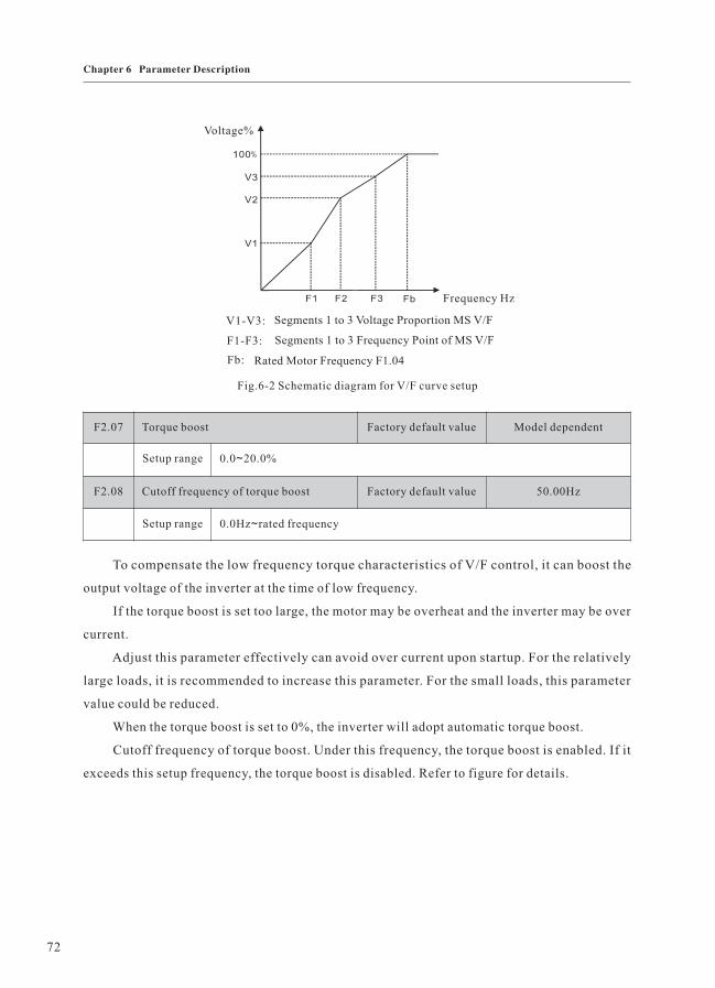
Voltage%
Frequency Hz
V1-V3:
F1-F3:
Fb:
Segments 1 to 3 Voltage Proportion MS V/F
Segments 1 to 3 Frequency Point of MS V/F
Rated Motor Frequency F1.04
Fig.6-2 Schematic diagram for V/F curve setup
F2.07 Torque boost Factory default value Model dependent
Setup range 0.0 20.0%~
F2.08 Cutoff frequency of torque boost Factory default value 50.00Hz
Setup range 0.0Hz rated frequency~
To compensate the low frequency torque characteristics of V/F control, it can boost the
output voltage of the inverter at the time of low frequency.
If the torque boost is set too large, the motor may be overheat and the inverter may be over
current.
Adjust this parameter effectively can avoid over current upon startup. For the relatively
large loads, it is recommended to increase this parameter. For the small loads, this parameter
value could be reduced.
When the torque boost is set to 0%, the inverter will adopt automatic torque boost.
Cutoff frequency of torque boost. Under this frequency, the torque boost is enabled. If it
exceeds this setup frequency, the torque boost is disabled. Refer to figure for details.
72
Chapter 6 Parameter Description

Vb output voltage
V1
f1 fb output frequency
V1: manual torque boost voltage
f1: cutoff frequency of torque boost
Vb: rated output voltage
fb: rated frequency
Fig. 6-3 Schematic diagram for manual torque boost
It is active only for V/F control. By setting this parameter, it can compensate the slip in the
V/F control mode due to load and reduce the variation of the motor rotation velocity which is
change with the variety of the load. In general, 100% corresponds to the rated slip of the motor
with rated load. Slip coefficient adjustment can refer to the following principles: When the load
is rated load and the slip compensation coefficient is set to 100%, the rotation velocity of the
motor in the inverter is close to the reference velocity. If the actual rotation velocity is lower
than the reference velocity, the coefficient should be increased accordingly and vice versa.
F2.10 Automatic voltage regulation (AVR)
selection
Factory default value 2
Setup range 0 Disabled
1 Enabled
2 Disabled only at time of deceleration
AVR is output voltage regulate automatically, which means when input voltage fluctuates,
the inverter adjusts automatically and keep the output voltage stable so as to overcome motor
radiation for higher output voltage and power shortage for lower output voltage. The parameter
can choose the effective session of AVR. When deceleration stopped, AVR selection disabled,
deceleration time will shorten but running current will become large, when AVR selection enabled,
deceleration time will lengthen but running current will decrease.
F2.11 Oscillation suppression gain Factory default value 15
Setup range 0 100~
73
Chapter 6 Parameter Description

The function is used to suppress the fixed oscillation while inverter is matching up motor.
If the output current varied again and again while the constant load running, you can adjust the
function code based on the factory default value to eliminate oscillation and make the motor
running on an even keel.
F2.12 Carrier frequency Factory default value Model dependent
Setup range 1.0 9.0kHz~
This function is used to adjust the carrier frequency of the inverter. By adjusting the carrier
frequency, the motor noise can be reduced, and the resonance of the mechanical system can be
avoided, so that the leakage current to the earth and the interference of the inverter can be reduced.
When the carrier frequency is low, the output current higher harmonic component will
increase, the loss of motor will increase, and the motor temperature rise will also increase.
When the carrier frequency is high, the loss of motor is reduced, and the motor temperature
is decreased, but the loss of the inverter and its temperature rise will increase and so will the
interference.
The adjustment of carrier frequency will have influences on the following performances:
Carrier frequency low to high
Motor noise high to low
Output current wave form poor to good
Motor temperature rise high to low
Inverter temperature rise low to high
Leakage current low to high
External radiation
interference
low to high
74
Chapter 6 Parameter Description

Group F3 Input Terminal
F2.13 Carrier frequency adjustment selection Factory default value 2
Setup range 0 Fixed PWM, and carrier frequency temperature adjustment disabled.
1 Random PWM, and carrier frequency temperature adjustment disabled.
2 Fixed PWM, and carrier frequency temperature adjustment actived.
3 Random PWM, and carrier frequency temperature adjustment actived.
Two kinds of PWM carrier frequency adjustment modes are provided: fixed and random.
The random PWM motor noise has wide frequency range, while the fixed PWM motor noise has
fixed frequency.
When the carrier wave temperature adjustment is enabled, the inverter can automatically
adjust the carrier frequency in term with its temperature. This function can reduce the possibility
of over heat alarm of the inverter.
F3.00 X1 terminal function selection Factory default value 26(FWD)
F3.01 X2 terminal function selection Factory default value 6(JOGF)
F3.02 X3 terminal function selection Factory default value 28(RST)
F3.03 X4 terminal function selection Factory default value 0
F3.04 X5 terminal function selection Factory default value 0
This parameter is used to set the function of the multifunctional digital input terminals.
Setup value Function Description
0 No function Even if there is signal input, the inverter has no action. The
unused terminals can be set as non-function to prevent error
action.
1 MS speed terminal 1 It can realize 16S speed through the combination of digital
status of these four terminals.
Details about the combination refers to attached drawing 1.2 MS speed terminal 2
3 MS speed terminal 3
4 MS speed terminal 4
75
Chapter 6 Parameter Description

Setup value Function Description
5 Three-line mode
running control
This terminal is used to realize three-line control mode of
terminal command. As for detailed description, please refer
to F3.06 function code.
6 Forward rotation
jog(JOGF)
For details about frequency and jog acceleration/
deceleration time during the jog running, refer to function
codes F7.00 to F7.02.7 Reverse rotation
jog(JOGR)
8 Terminal UP When the frequency is provided by the external terminals,
then modify the frequency UP/DOWN command. When the
frequency source is set as the digital setup, it can regulate
the setup frequency up and down.
9 Terminal DOWN
10 Coast to stop The inverter locks the output and loses control of the
process of motor stop. It is the method that is often adopted
when there are large amount of loads and no requirements
for the stop time. This mode has the same meaning as that of
F5.05.
11 Running pause The inverter decelerates to stop, but the running parameters
are all in memory status, such as PLC parameter, swing
frequency parameter and PID parameter. When this signal
disappeared, the inverter restores to the status before
stopping.
12 External fault input When the external fault signal was sent to the inverter. the
inverter reports fault(E.EF)and stops.
13 Acceleration/
deceleration selection
terminal 1
It can select four kinds of acceleration/deceleration time
through the combination of digital status of these two
terminals. Refer to the attached drawing 2.
14 Acceleration/
deceleration selection
terminal 2
15 Frequency source
switching
When the frequency source selection(F0.07)is set as 3, it
performs switching between the main frequency source X
and the auxiliary frequency source Y via this terminal.
When the frequency source selection(F0.07)is set as 4 or 5,
it performs switching between the frequency source X or Y
and (X plus Y)via this terminal.
76
Chapter 6 Parameter Description

Setup value Function Description
16 UP/DOWN setup clear
(terminal and keyboard)
When the frequency reference is digital frequency
reference, this terminal can be used to clear the frequency
value modified by UP/DOWN and thus restore the reference
frequency to the setup value of F0.08.
17 DC brake input
command DB of stop
It can realize exigency stop of motor and exact orientation.
Brake start frequency, brake waiting time and brake current
are defined in F5.06 to F5.09.
18 Acceleration/
deceleration disabled
Protect the inverter from affecting by the external signals
(except stop command), and maintain the current
frequency.
19 PID pause PID is disabled temporarily, and the inverter maintains the
current frequency to output.
20 PLC status reset PLC pauses during the execution process. When it resumes
running, it can effectively restore to the initial status of
simple PLC via this terminal.
21 Swing frequency pause The inverter outputs with central frequency. Swing
frequency pause.
22 Counter reset Clear the counter status.
23 Length reset Length clear.
24 Timing reset Actual running time clear
25 PID second reference
value enable switching
terminal
The PID setup value can be switched from the setup value
selected by F9.00 to the value selected by F9.03 via this
terminal.
26 Forward rotation(FWD) The forward/reserve rotation of the inverter were controlled
by the external terminal.27 Reserve rotation(REV)
28 Fault reset(RST) Its function is as the same as that of keyboard.
29 Disconnection reset
terminal
Exit disconnection status.
30 Disconnection proximity
switch
Input terminal of disconnection proximity switch.
31 Counter Input terminal of counting pulse.
77
Chapter 6 Parameter Description

Setup value Function Description
32 Length count Input terminal of length counting pulse.
33 Disconnection detective
disabled enabled
terminal
When the terminal is enabled, disconnection detective is
disabled.
K1 K2 K3 K4 Frequency setup Corresponding parameter
OFF OFF OFF OFF MS speed 0 FB.00
OFF OFF OFF ON MS speed 1 FB.01
OFF OFF ON OFF MS speed 2 FB.02
OFF OFF ON ON MS speed 3 FB.03
OFF ON OFF OFF MS speed 4 FB.04
OFF ON OFF ON MS speed 5 FB.05
OFF ON ON OFF MS speed 6 FB.06
OFF ON ON ON MS speed 7 FB.07
ON OFF OFF OFF MS speed 8 FB.08
ON OFF OFF ON MS speed 9 FB.09
ON OFF ON OFF MS speed 10 FB.10
ON OFF ON ON MS speed 11 FB.11
ON ON OFF OFF MS speed 12 FB.12
ON ON OFF ON MS speed 13 FB.13
ON ON ON OFF MS speed 14 FB.14
ON ON ON ON MS speed 15 FB.15
Attached drawing 1
78
Chapter 6 Parameter Description

Terminal 2 Terminal1 Acc/Dec time selection Corresponding parameter
OFF OFF Acc/Dec time 1 F0.13、F0.14
OFF ON Acc/Dec time 2 F7.04 F7.05、
ON OFF Acc/Dec time 3 F7.06 F7.07、
ON ON Acc/Dec time 4 F7.08 F7.09、
Attached drawing 2
K1 K2 Running Command
0 0 Stop
1 0 Forward Rotation
0 1 Reverse Rotation
1 1 Stop
K1
K2FWD
REVCM
F3.06 Terminal command mode Factory default value 0
Setup range 0 Two-line mode 1
1 Two-line mode 2
2 Three-line mode 1
3 Three-line mode 2
This parameter defines four different modes to control the operation of the inverter via the
external terminal.
0: Two-line running mode1: this mode is the most commonly used one. The forward/reverse
rotation of the motor is decided by the commands of FWD and REV terminals.
Fig. 6-4 Two-line running mode 1
1: Two-line running mode 2: when this mode is adopted, REV is enabled terminal. The
direction is determined by the status of FWD.
K1
0
1
0
1
K2
0
0
1
1
Running Command
Stop
Forward Rotation
Reverse Rotation
Stop
K1
K2FWD
REV
CM
Fig. 6-5 Two-line running mode 2
79
Chapter 6 Parameter Description

WD
REV
Xn
CM
F
SB2
SB1
SB3
WD
Xn
F
SB1
Sb2
K
Running Direction
Selection
Forward Rotation
Reverse Rotation
K
0
1
2: Three-line running mode 1: In this mode, Xn is enabled terminal, and the direction is
controlled by FWD and REV, respectively. However, the pulse is enabled by disconnecting the
signal of Xn terminal when the inverter stops.
Fig. 6-6 Three-line running mode 1
Where:
SB1: Stop button
SB2: Forward rotation button
SB3: Reverse rotation button
3: Three-line running mode 2: In this mode, Xn is enabled terminal, and the running command
is given by FWD(pulse enabled), while the direction is determined by the status of REV. Stop
command is performed by disconnecting the Xn signal.
REV
CM
Fig. 6-7 Three-line running mode 2
Where:
SB1: Stop button
SB2: Running button
Prompt:
Xn is a kind of multifunctional input terminal. In this way, its corresponding terminal function
shall be defined as NO.5 function“Three-line mode running control”.
Under the control of terminal, as for two-line running mode 1 or 2, though it is terminal level
enabled, when stop command given by other source that makes the inverter stop, it can’t give
running command in spit of the still enabled control terminals FWD/REV. To make the inverter
80
Chapter 6 Parameter Description

running again, there is necessity to trigger the enabled status of FWD/REV again, such as terminal
function PLC single cycle stop, exact stop, and effective stop of the STOP key under the command
of terminal running channel. (Refer to the description of function code in F0.02.)
F3.07 Terminal UP/DOWN velocity Factory default value 1.00Hz/s
Setup range 0.01 100.0Hz/s~
Terminal UP/DOWN is used to adjust the change rate when setting the frequency.
F3.08 AI minimum input Factory default value 0.00V
Setup range 0.0V 10.00V when current inputs: 1V corresponds to 2mA~
F3.09 AI minimum input corresponding setup Factory default value 0.0%
Setup range -100.0 100.0%~
F3.10 AI maximum input Factory default value 10.00V
Setup range 0.0V 10.00V~
F3.11 AI maximum input corresponding setup Factory default value 100.0%
Setup range -100.0 100.0%~
F3.12 Function reserved Factory default value
F3.13 Function reserved Factory default value
F3.14 Function reserved Factory default value
F3.15 Function reserved Factory default value
The above function codes define the relations between the analog input voltage setup value
and the analog input representative setup value. When the analog input voltage exceeds the setup
maximum input, it will be calculated according to the maximum input. When the analog input
voltage is lower than the minimum input, the setup is 0. The nominal value of the analog setup
100% varies with the application situation. For details, please refer to the description of each
application part.
81
Chapter 6 Parameter Description

Steer stick mode: the above parameters are set in reason, it can realize the forward/reverse
rotation of the motor through changing the analog input, this mode usually called JOYST mode,
details about the setup is as follow:
The minimum value of signal corresponding to the maximum reference of reverse, the
maximum value of signal corresponding to the maximum reference of forward, and the minimum
input shall be 0.3V(0.6mA) or a little bigger. Because by using the 0 to 10V signal as reference,
once the reference signal lost, the inverter might run toward the reverse at the highest speed by
mistake. To avoid the mistake, the minimum input can’t be too low so that when the reference
signal lost, the inverter will stop automatically.
Several setting examples are shown in the following figures:
100.0%
Forward maximum
frequency
corresponding settings
(frequency,etc)
0.0%0V
(0mA)
10V
(20mA)
AI
Fig.6-8
Corresponding relationship between analog reference as
main frequency source reference and output frequency
n%
corresponding settings
(frequency,etc)
-n%
0V
(0mA)
10V
(20mA)AI
Fig.6-9
Analog reference as auxiliary frequency source for
main frequency source micro tuning
82
Chapter 6 Parameter Description

100.0%
Forward maximum
frequency
corresponding settings
(frequency,etc)
0.3V
(0.6mA)
10V
(20mA)AI
Fig.6-10
-100.0%
Reserve maximum
frequency
JOYST mode: corresponding relationship
between analog reference and setup value
Prompt: The above cutlines are typical application settings. As for the setting details, the
adjustment shall be made to meet the demand of customers.
F3.16 Pulse input(DI)lower limit frequency Factory default value 0.00kHz
Setup range 0.00kHz (F3.18)~
F3.17 Pulse input(DI)lower limit frequency
corresponding setup
Factory default value 0.0%
Setup range -100.0 100.0%~
F3.18 Pulse input(DI)upper limit frequency Factory default value 10.00kHz
Setup range (F3.16) 10.00kHz~
F3.19 Pulse input(DI)upper limit frequency
corresponding setup
Factory default value 100.0%
Setup range -100.0 100.0%~
This group of function code defines the corresponding relationship between the input pulse
signal frequency and the setup value when the select pulse reference enabled.
F3.20 Analog input filter time Factory default value 0.25s
Setup range 0.01s 10.00s~
The function code determines the sensitivity of analog input AI. If error action is made due
to prevent the analog input from interferences, this parameter can be increased to enhance the
anti-interference capability. But the sensitivity of the analog input will be lowered.
83
Chapter 6 Parameter Description

Group F4 Output Terminal
Inverter has following output terminals:
1: One multifunctional digital output terminal;
2: One multifunctional relay output terminal;
3: AO: Output voltage signal.
F4.00 Relay output selection Factory default value 2
F4.01 OC output selection Factory default value 1
F4.02 Function reserved Factory default value
The function selection of multifunctional output terminal is as follows:
Setup value Function Description
0 No output The output terminals don’t have any function.
1 Inverter is running Inverter is running, and there is output frequency(can be
zero), ON signal will be output at this time.
2 Fault output When the inverter is faulty, it outputs ON signal.
3 FDT1 output Please refer to function code F7.15 and F7.16 for details.
4 FDT2 output Please refer to function code F7.17 and F7.18 for details.
5 Frequency arrival Please refer to function code F7.19 for details.
6 At the zero speed
running
When the inverter output frequency is less than the start
frequency, it outputs ON signal.
7 Inverter overload
pre-warning
According to the warning system setting of F8.00, once the
output current exceeds the pre-warning value, it outputs ON
signal after the setup time of F8.01.
8 Setup counting value
arrival
As for the action mode of output terminal, please refer to
function code FA.08 and FA.09 for details.
9 Designated counting
value arrival
10 Setup length arrival When the measured actual length exceeds the setup value of
FA.06, it outputs ON signal.
84
Chapter 6 Parameter Description

Setup value Function Description
11 PLC circulation
completion
When the simple PLC has been running for one cycle, it
outputs a pulse signal with width of 500ms.
12 PLC phase completion When the simple PLC has been running for one phase, it
outputs a pulse signal with width of 500ms.
13 Setup running time
arrival
When the actual running time of the inverter exceeds the
setup time FA.10 , it outputs ON signal.
14 Output frequency arrive
at upper limit
When the running frequency reaches the frequency upper
limit F0.11, it outputs ON signal.
15 Output frequency arrive
at lower limit
When the running frequency is less than the frequency
lower limit F0.12, it outputs ON signal.
16 Output X1 The status of input terminal X1 outputs through output
terminal.
17 Output X2 The status of input terminal X2 outputs through output
terminal.
18 Running command When inverter received the running command, the output
enabled.
19 Reserved
20 Dormant When PID running is in dormant status.
21 Ready for running When the inverter is in running status, it outputs ON signal.
22 There-line running mode
1 start to trigger
information output by
itself
The inverter allows to run and output the trigger signal
when it is not at running status.
23 Band-type brake
information output
It starts output when output frequency lower than FDT2 at
the first time, the time length is setting by OC break
protract.
24 Disconnection detection
output
It outputs when accords with the disconnection judgement
terms.
25 Reference length arrival When the measured actual length exceeds the setup value of
FA.06, it outputs ON signal.
85
Chapter 6 Parameter Description

F4. 04 F4. 05
break protract
Select control
signal
OC terminal
output status
close protract
F4.03 Function reserved Factory default value —
F4.04 OC close protract Factory default value 0.0s
Setup range 0 1000.0s~
F4.05 OC break protract Factory default value 0.0s
Setup range 0 1000.0s~
F4.06 Function reserved Factory default value
F4.07 Function reserved Factory default value
Fig.6-11
Schematic diagram for
OC output closed/ Break protract
F4.08 AO output channel selection Factory default value 0
Setup range 0: 0 10V
1: 2
~
~10V
F4.09 AO output gain Factory default value 100.0%
Setup range 1.0% 500.0%~
1: The output gain coefficient is generally used to correct the analog output deviation.
Application examples of AO output analog signal are shown as followings:
Client hoped that AO outputs content selection: running frequency (0.0Hz to the frequency
upper limit); corresponding AO output: 0 to 5V voltage signal. These are shown as the following
figure.
86
Chapter 6 Parameter Description

0V
5V
0.0Hz frequency upper limit
Setup : the first part of F4.08 is 0 F4.09=50.0% F4.11=0、 、
F4.10 Function reserved Factory default value
F4.11 AO output selection Factory default value 0
F4.12 Function reserved Factory default value
The corresponding value range that it indicates is shown in the table below:
Setup value Function Description
0 Running frequency 0 maximum frequency F0.11~
1 Setup frequency 0 maximum frequency F0.11~
2 Output current 0 200% of the rated current of the inverter~
3 Output voltage 0 rated voltage of the inverter~
4 Pulse reference(DI) 0.0 DI maximum pulse input frequency F3.18~
5 AI 0 10V~
6 Reserved
7 Length 0 setup length~
8 Counting value 0 setup counting value~
9 Running time 0 FA.10~
10 Output torque 0 200% of the rated torque of the motor~
11 Output power 0 twice rated power~
12 Keyboard potentiometer 0 maximum value~
87
Chapter 6 Parameter Description

Group F5 Start/Stop Control
F5.00 Start mode Factory default value 0
Setup range 0 Start from start frequency
1 Perform braking prior to start
2 Velocity tracking restart
0: Start from start frequency
To start according to setup start frequency(F5.01) and setup start frequency retention time
(F5.02).
1: Perform braking prior to start
Perform DC braking prior to start(refer to F5.04 F5.05).、
It is applicable to the applications where reverse rotation is likely to occur when small loads
are started.
2: Velocity tracking restart
Track the rotation velocity and direction of the motor automatically, and make the rotating
motor working smoothly without surge.
It is applicable to the restart upon transient power failure due to large loads.
F5.01 Start frequency Factory default value 0.5Hz
Setup range 0.0Hz 10.0~ Hz
F5.02 Start frequency retention time Factory default value 0.0s
Setup range 0.0 36.0s~
To ensure the torque at the start of inverter, it needs to set a proper start frequency. In addition,
to set up flux at the time of starting motor, accelerate the start frequency after a certain period of
time. The start frequency value F5.01 is not confined by the frequency lower limit.
When the frequency reference value (frequency source) is lower than the start frequency, the
inverter cannot start and is in standby status.
When the forward rotation and reverse rotation switches to each other, the start frequency
retention time is disabled. The retention time is not included in the acceleration time but in the
running time of simple PLC.
88
Chapter 6 Parameter Description

F5.03 DC brake current at start Factory default value 0%
Setup range 0 100%~
F5.04 DC brake time at start Factory default value 0.0s
Setup range 0.0 36.0s~
DC brake is generally used when the motor is restarted after it stops completely.
F5.03 and F5.04 only enabled when the start running mode selects the braking prior to start
mode(F5.00=1), and when F5.04 is 0.0s, it has no start DC braking process.
The setup DC brake current at start is relative to the percentage of the rated current of the
inverter.
The higher the DC brake current is, the higher the brake force is.
When DC brake at start enabled, the inverter firstly performs DC brake in accordance with
the DC brake current at start, and then start running after the setup time of DC brake at start.
The process of DC brake is shown as the following figure:
Outputfrequency
Outputvoltage
DC brakequantity
DC
brake
time
Runningcommand
Time
Time
Fig.6-12 Schematic diagram for DC automatic start mode
F5.00 Stop mode Factory default value 0
Setup range 0 Decelerate to stop
1 Coast to stop
89
Chapter 6 Parameter Description

0: Decelerate to stop
After receiving the stop command, the inverter will reduce the output frequency in accordance
with the deceleration mode and stops when the frequency reduced to zero.
1: Coast to stop
After receiving the stop command, the inverter will terminate the output immediately. The
load will coast to stop according to the mechanical inertia.
F5.06 DC brake beginning frequency at stop Factory default value 0.0Hz
Setup range 0.0Hz maximun frequency~
F5.07 DC brake waiting time at stop Factory default value 0.0s
Setup range 0.0 36.0s~
F5.08 DC brake current at stop Factory default value 0%
Setup range 0 100%~
F5.09 DC brake time at stop Factory default value 0.0s
Setup range 0.0 36.0s~
During the process of deceleration to stop, when the running frequency reaches DC brake
beginning frequency and in course of the DC brake waiting time at stop (F5.07), the DC brake
quantity will be inflicted until it reached the DC brake time at stop (F5.09).
Inverter has no output during the DC brake waiting time at stop. As for high-power motor,
the setup time can prevent the over-high current at the brake beginning moment.
The setup of DC brake current at stop is relative to the percentage of rated current of inverter.
The higher the value is, the better the DC brake effect is.
When the DC brake time at stop is 0.0s, there is no DC brake process.
F5.10 Beginning voltage of dynamic braking Factory default value 130%
Setup range 115 140%~
F5.11 Use ratio of dynamic braking Factory default value 30.0%
Setup range 0 100%~
It is enabled for the inverter with built-in brake unit. It can be used to adjust the brake effect
of the brake unit.
90
Chapter 6 Parameter Description

F5.12 Acceleration/deceleration mode Factory default value 0
Setup range 0 Straight acceleration/deceleration
1 S-curve acceleration/deceleration
It is used to select the frequency change mode during the inverter start and stop process.
0: straight acceleration/deceleration
The output frequency increases or decreases along with the straight line. The acceleration/
deceleration time varies with the setup acceleration/deceleration time. EH600S series inverter
provides four types of acceleration/deceleration time. It can select acceleration/deceleration time
via the multifunctional digital input terminals(F3.00 to F3.04).
1: S-curve acceleration/deceleration
The output frequency increases or decreases along with the S curve. S curve is generally used
in the applications where start and stop process are relatively flat, such as elevator and conveyor
belt. Refer to F5.13 and F5.14 for the meanings of the parameters.
F5.13 Start segment proportion of S curve Factory default value 30.0%
Setup range 0.0 40.0%~
F5.14 End segment proportion of S curve Factory default value 30.0%
Setup range 0.0 40.0%~
t1 in the following figure is the parameter defined in F5.13, within which the output frequency
change slop increases gradually. t2 is the time defined in F5.14, within which the slop of the output
frequency change gradually decreases to zero. Within the time between t1 and t2, the slop of the
output frequency change remains fixed.
t1 t1t2 t2
Fmax
Frequency
Time
acceleration time deceleration time
Fig.6-13 Schematic diagram for S curve acceleration/deceleration
91
Chapter 6 Parameter Description

Group F6 Keyboard and Display
F6.00 S key function selection Factory default value 1
Setup range 0 S key function inactive
1 Forward rotation jog command
2 Reserve rotation run command
3 Clear the data of exact stop process
S key refers to multifunctional key. It can set and define the function of S key on the keyboard
via this parameter.
0: This key has no function
1: Forward rotation jog command
It can realize forward rotation jog(FJOG) through the S key on the keyboard.
2: Reserve rotation run command
The S key of operation panel used as the input of the reverse rotation run command, when the
keyboard control mode (F0.02) is 0, press the key, then the inverter will output frequency from
the reverse phase order.
3: When the exact stop mode is enabled (FA.11 0), press S key, then the data of the exact≠
stop process will be clean out.
Please refer to the detailed description of exact stop mode.FA.11for
F6.01 LED running display parameter 1 Factory default value 5
Setup range 0 8191~
F6.02 LED running display parameter 2 Factory default value 0
Setup range 1 8191~
F6.03 LED stop display parameter 1 Factory default value 1
Setup range 0 8191~
F6.04 LED stop display parameter 2 Factory default value 0
Setup range 1 8191~
92
Chapter 6 Parameter Description

In stop or running status, when the status parameter (FV)needs to be inquired again and again,
by setting running parameter (F6.01 to F6.02)and stop parameter(F6.03 to F6.04), and realizing
the common-using status parameter by controlling the shift key (>>) to display in turns. The parameter
value of F6.01 to F6.04 is set according to binary system, input by transforming it into decimal system.
When there needs to display one parameter of FV, you only need to set the corresponding
binary bite of F6.01 to F6.04 as 1.
The corresponding relationship between the binary bite of F6.01 F6.02 running display、
parameter and FV parameter number is shown as attached fig.3.
There are two examples about the setup way of F6.01 to F6.04 in the following.
1: Client wants to display FV.00, FV.02 and FV.18 circularly in the running state.
Setting as following: F6.01=1+4=5 F6.02=32
2: Client wants to display the setup frequency (FV.01) in the stop state.
Setting as following: F6.03=2
1024
4096
F6.01 LED running display parameter 1 corresponding relationship
between binary and decimal
Setup
range
0 8191~ FV.00: Output frequency
FV.01: Setup frequency(flashes)
FV.02: Output current
FV.03: Running rev
FV.04: Setup rev(flashes)
FV.05: Running load speed
FV.06: Setup load speed(flashes)
FV.07: Output voltage
FV.08: Bus voltage
FV.09: Input AC voltage
FV.10: AI
FV.11: Reserved
FV.12: Pulse reference (DI)
If the above parameters need to be displayed during the operation, set
the corresponding bit to 1, and set them into F6.01 after changing the
binary numbers into decimal numbers.
2
2
2
2
2
2
2
2
2
2
2
2
2
=
=
=
=
=
=
=
=
=
=
=
=
=
10
1
2
3
4
5
6
7
8
9
10
11
12
2
4
8
16
32
64
128
512
2048
256
93
Chapter 6 Parameter Description

1024
4096
F6.02 LED running display parameter 2 corresponding relationship
between binary and decimal
Setup
range
1 8191~ FV.13: PID setup(flashes)
FV.14: PID feedback
FV.15: Terminal status
FV.16: Actual counting value
FV.17: Setup counting value(flashes)
FV.18: Actual length
FV.19: Setup length(flashes)
FV.20: Actual running time
FV.21: Setup running time(flashes)
FV.22: AO output
FV.23: Reserved
FV.24: Radiator temperature
FV.25: Total running time
If the above parameters need to be displayed during the operation, set the
corresponding bit to 1, and set them into F6.02 after changing the binary
numbers into decimal numbers.
F6.03 LED stop display
parameter 1
The corresponding relationship between binary in F6.03 and FV
parameter number is as the same as that of F6.01
Setup
range
0 8191~
F6.04 LED stop display
parameter 2
The corresponding relationship between binary in F6.04 and FV
parameter number is as the same as that of F6.02
Setup
range
1 8191~
2
2
2
2
2
2
2
2
2
2
2
2
2
=
=
=
=
=
=
=
=
=
=
=
=
=
10
1
2
3
4
5
6
7
8
9
10
11
12
2
4
8
16
32
64
128
512
2048
256
Attached fig.3
94
Chapter 6 Parameter Description

F6.05 Auxiliary supervise Factory default value 1
Setup range 0 25~
The parameter is used to set FV parameter number of underside range LED display of the
double range LED operation panel, please refer to FV parameter of page 35 for the details.
It is the content of underside range LED display that make it convenient for the client to debug
and monitor inverter running. As for users who use exact stop function can realize setup value
displaying and actual value displaying at the same time through the double range LED.
F6.06 Load speed display coefficient Factory default value 1
Setup range 0.0 100.0~
The output frequency of the inverter and the load speed are corresponding together through
this parameter. It is set when the load speed needs to be displayed.
F6.07 Function reserved Factory default value —
F6.08 User password 0 9999~ Factory default value 0
Once any non-zero number be set, the password protection function will be enabled.
0: Clear the previous user password setup and make the password protection function invalid.
To view F6.08 under the status of password protection, the LED will prompt user that the
parameter is hidden, you can only view and modify this parameter when the password input
correctly. Please remember the user password correctly. If the password is set wrongly or forgotten,
please contact the manufacturer. Refer to the description of password setting in 4.5 section.
F6.09 Copy keyboard function selection Factory default value 0
Please refer to the copy keyboard description of our company.
95
Chapter 6 Parameter Description
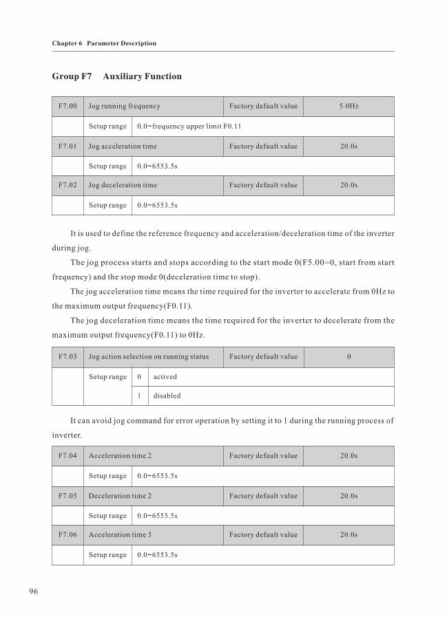
Group F7 Auxiliary Function
F7.00 Jog running frequency Factory default value 5.0Hz
Setup range 0.0 frequency upper limit F0.11~
F7.01 Jog acceleration time Factory default value 20.0s
Setup range 0.0 6553.5s~
F7.02 Jog deceleration time Factory default value 20.0s
Setup range 0.0 6553.5s~
It is used to define the reference frequency and acceleration/deceleration time of the inverter
during jog.
The jog process starts and stops according to the start mode 0(F5.00=0, start from start
frequency) and the stop mode 0(deceleration time to stop).
The jog acceleration time means the time required for the inverter to accelerate from 0Hz to
the maximum output frequency(F0.11).
The jog deceleration time means the time required for the inverter to decelerate from the
maximum output frequency(F0.11) to 0Hz.
F7.03 Jog action selection on running status Factory default value 0
Setup range 0 actived
1 disabled
It can avoid jog command for error operation by setting it to 1 during the running process of
inverter.
F7.04 Acceleration time 2 Factory default value 20.0s
Setup range 0.0 6553.5s~
F7.05 Deceleration time 2 Factory default value 20.0s
Setup range 0.0 6553.5s~
F7.06 Acceleration time 3 Factory default value 20.0s
Setup range 0.0 6553.5s~
96
Chapter 6 Parameter Description

F7.07 Deceleration time 3 Factory default value 20.0s
Setup range 0.0 6553.5s~
F7.08 Acceleration time 4 Factory default value 20.0s
Setup range 0.0 6553.5s~
F7.09 Deceleration time 4 Factory default value 20.0s
Setup range 0.0 6553.5s~
Acceleration/deceleration time can select F0.13 and F0.14 and the above three types of
acceleration/deceleration time. Their meanings are the same.
It can select acceleration/deceleration time 1 to 4 during the inverter running precess through
the different combination of multifunctional digital input terminal X. Please refer to the description
of Group F3(Input terminal).
The above acceleration/deceleration time can also be used to satisfy the local need under
the mode of PLC running.
F7.10 Skip frequency Factory default value 0.0Hz
Setup range 0.0Hz frequency upper limit F0.11~
F7.11 Skip frequency amplitude Factory default value 0.0Hz
Setup range 0.0Hz frequency upper limit F0.11~
When the setup frequency is within the range of skip frequency, the actual running frequency
will be in the skip frequency boundary close to the setup frequency.
It can make the inverter run away from the mechanical resonance point of the load through
setting the skip frequency.
If the two skip frequency are set to zero, this function will be disabled.
Fig.6-14 Schematic diagram for Skip frequency
Skip frequency amplitudeSkipfrequency Skip frequency amplitude
Frequency setting signal
97
Chapter 6 Parameter Description

Output frequency
Running time
dead zone time
F7.12 Forward/reverse rotation dead-zone time Factory default value 0.0s
Setup range 0.0 3000.0s~
During the setting of forward/reverse rotation of the inverter, the transition time at the output
zero frequency position. It is shown as the following figure:
Fig.6-15 Schematic diagram for forward/reverse
rotation dead-zone time
F7.13 Reverse control Factory default value 0
Setup range 0 actived
1 disabled
When the parameter is set as 0: Reverse rotation control is active;
When the parameter is set as 1: Reverse rotation control is inactive.
The parameter is enabled for all command sources.
F7.14 Reverse control Factory default value 0
Setup range 0 Run with frequency lower limit
1 Stop
2 Running with zero velocity
It is used to select the running status of the inverter when the setup frequency is lower than the
frequency lower limit.
In order to avoid the motor always running with low velocity, this function can be used to stop.
98
Chapter 6 Parameter Description

F7.15 Frequency detection value(FDT1 level) Factory default value 50.0Hz
Setup range 0.0Hz frequency upper limit F0.11~
F7.16 Frequency detection hysteresis (FDT1
hysteresis)
Factory default value 2.0Hz
Setup range 0.0Hz frequency upper limit F0.11~
F7.17 Frequency detection value(FDT2 level) Factory default value 50.0Hz
Setup range 0.0Hz frequency upper limit F0.11~
F7.18 Frequency detection hysteresis (FDT2
hysteresis)
Factory default value 2.0Hz
Setup range 0.0Hz frequency upper limit F0.11~
ON
Output frequency
FDT1 Hysteresis
Output Terminal
FDT1 Level
Time
Time
It is used to set the detection value of output frequency and hysteresis value upon removing of
the output action.
Fig.6-16 Schematic diagram for FDT level
F7.19 Frequency arrival detection amplitude Factory default value 2.0Hz
Setup range 0.0Hz frequency upper limit F0.11~
When the output frequency of the inverter reached the setup frequency value, this function can
be used to adjust the detection amplitude, it is shown as the following figure.
99
Chapter 6 Parameter Description

Setupfrequency Detected Amplitude
Time
Time
ON
Output Terminal
Output frequency
Fig.6-17 Schematic diagram for Detection amplitude
Group F8 Fault and Protection
F8.00 Inverter overload pre-warning Factory default value 110%
Setup range 50 200%~
F8.01 Inverter overload pre-warning delayed
time
Factory default value 2.0s
Setup range 0.0 20.0s~
The reference for this value is the inverter rated current. When the inverter detects that the
output current exceeds the corresponding current of parameter F8.00 continuously, it outputs
pre-warning signal from OC or relay, after the delayed time of F8.01.
F8.02 Overload、 overheat protective action
mode
Factory default value 0
Setup range 0 Inverter locks output
1 Limitative current running(alarm)
The parameter set the inverter protective action mode when it is overload or overheat.
0: The inverter locks output immediately. When it is overload or overheat, the inverter locks
output and the motor coasts to stop.
1: Limitative current running(alarm). When it is overload or overheat, the inverter might reduce
the output frequency to decrease the load current at this time.
100
Chapter 6 Parameter Description

F8.03 Motor overload protection coefficient Factory default value 100%
Setup range 30.0 100.0%~
The reference for this value is the motor rated current/inverter rated current. When the inverter
output current exceeds F8.03 the inverter rated output current for a certain time, the inverter reportsx
motor overload fault.
F8.04 Stall protection current over current Factory default value 150%
Setup range 110 200%~
Select the protection point for function of stall over current. When the value is exceeded, the
inverter starts executing the protection function for stall over current.
F8.05 Stall protection voltage over voltage Factory default value 130%
Setup range 120 150%~
Select the protection point for function of stall over voltage. When the value is exceeded, the
inverter starts executing the protection function for stall over voltage.
F8.06 Restart setup after power-off Factory default value 0
Setup range 0 No action
1 Action
F8.07 Restart waiting time after power-off Factory default value 1.0s
Setup range 0.1 10.0s~
When restart after power-off is enabled, inverter is on the running state before power cut. Then
the inverter will start automatically after the setup waiting time (it is set by F8.07) when power-on.
During the restart waiting time, the inverter won’t start, even though there inputs run command, if
there inputs stop command, it will finish the restart waiting state.
F8.08 Fault automatic reset time Factory default value 0
Setup range 0 3~
When the inverter selects fault automatic reset, it is used to set the times of automatic reset.
If the value is exceeded, the inverter will stop because of failure and wait for maintenance.
101
Chapter 6 Parameter Description
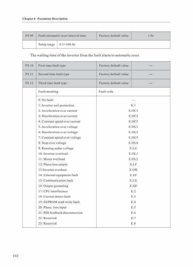
F8.09 Fault automatic reset interval time Factory default value 1.0s
Setup range 0.1 100.0s~
The waiting time of the inverter from the fault alarm to automatic reset.
F8.10 First time fault type Factory default value —
F8.11 Second time fault type Factory default value —
F8.12 Third time fault type Factory default value —
Fault meaning Fault code
0: No fault
1: Inverter unit protection
2: Acceleration over current
3: Deceleration over current
4: Constant speed over current
5: Acceleration over voltage
6: Deceleration over voltage
7: Constant speed over voltage
8: Stop over voltage
9: Running under voltage
10: Inverter overload
11: Motor overload
12: Phase loss output
13:Inverter overheat
14: External equipment fault
15: Communication fault
16: Output grounding
17: CPU interference
18: Current detect fault
19: EEPROM read-write fault
20: Phase loss input
21: PID feedback disconnection
22: Reserved
23: Reserved
--
E.1
E.OC1
E.OC2
E.OC3
E.OU1
E.OU2
E.OU3
E.OU4
E.LU
E.OL1
E.OL2
E.LF
E.OH
E.EF
E.CE
E.GF
E.2
E.3
E.4
E.5
E.6
E.7
E.8
102
Chapter 6 Parameter Description

Group F9 PID Function
F8.13 Output frequency upon fault Display the status of parameter upon fault for the
most recent one time.
As for terminal status expression upon fault,
please refer to the details in FV.15.
F8.14 Output current upon fault
F8.15 Bus voltage upon fault
F8.16 Module temperature upon fault
F8.17 Terminal state upon fault
PID function summarize:
PID control is a common method of process control. It adjusts the output frequency through
proportional, integral and differential calculations of the difference between the reference signal
of the controlled quantity and the feedback signal, and thus to stabilize the controlled quantity at
the target quality.
PID reference signal: It is the signal that corresponding to control target of the controlled
quantity.
PID feedback signal: It is the signal that measured by sensor and corresponding to the actual
value of the controlled quantity, it varied with process load and indicated the actual state during
the control process.
The differences between the actual status of the controlled quantity and the control target
will be reflected by the differences between PID feedback and the reference signal.
According to different symbols, PID controller rises or reduces output frequency accordingly
so as to achieve the autocontrol propose.
The built-in PID controller inverter is applicable to process control such as fluid control,
press control, temperature control and so on.
Prompt: When client needs to use the PID controller function, he should set the frequency
source selection parameter as PID enabled at first, which means F0.03(F0.04)=7.
F9.00 PID control mode setup Factory default value 001
Setup range The third part of LED: PID action direction
0: positive action 1 reverse action
The second part of LED: PID feedback source
0: AI 1 5: reserved 6: pulse setup(DI) 7:communication setup
The first part of LED: PID reference source
0: panel potentiometer 1: PID digital reference (F9.02) 2: AI
3: reserved 4: pulse setup(DI) 5:communication setup
:
~
103
Chapter 6 Parameter Description
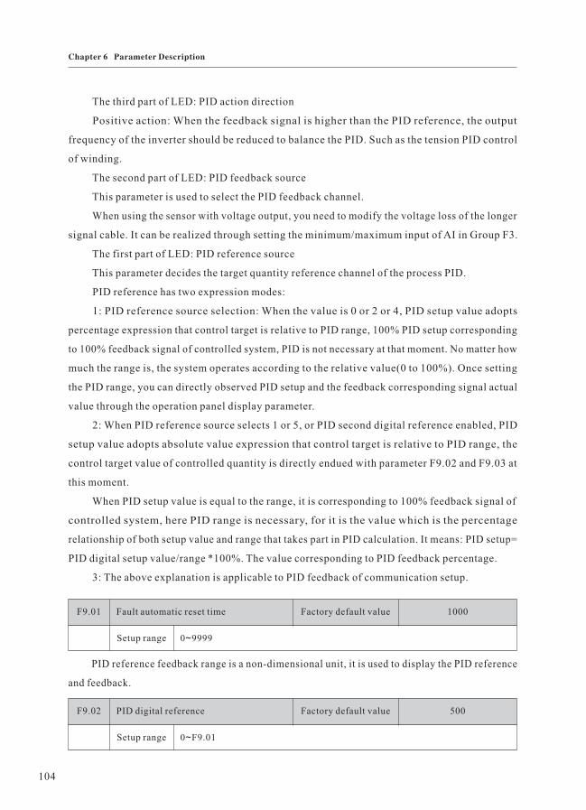
The third part of LED: PID action direction
Positive action: When the feedback signal is higher than the PID reference, the output
frequency of the inverter should be reduced to balance the PID. Such as the tension PID control
of winding.
The second part of LED: PID feedback source
This parameter is used to select the PID feedback channel.
When using the sensor with voltage output, you need to modify the voltage loss of the longer
signal cable. It can be realized through setting the minimum/maximum input of AI in Group F3.
The first part of LED: PID reference source
This parameter decides the target quantity reference channel of the process PID.
PID reference has two expression modes:
1: PID reference source selection: When the value is 0 or 2 or 4, PID setup value adopts
percentage expression that control target is relative to PID range, 100% PID setup corresponding
to 100% feedback signal of controlled system, PID is not necessary at that moment. No matter how
much the range is, the system operates according to the relative value(0 to 100%). Once setting
the PID range, you can directly observed PID setup and the feedback corresponding signal actual
value through the operation panel display parameter.
2: When PID reference source selects 1 or 5, or PID second digital reference enabled, PID
setup value adopts absolute value expression that control target is relative to PID range, the
control target value of controlled quantity is directly endued with parameter F9.02 and F9.03 at
this moment.
When PID setup value is equal to the range, it is corresponding to 100% feedback signal of
controlled system, here PID range is necessary, for it is the value which is the percentage
relationship of both setup value and range that takes part in PID calculation. It means: PID setup=
PID digital setup value/range *100%. The value corresponding to PID feedback percentage.
3: The above explanation is applicable to PID feedback of communication setup.
F9.01 Fault automatic reset time Factory default value 1000
Setup range 0 9999~
PID reference feedback range is a non-dimensional unit, it is used to display the PID reference
and feedback.
F9.02 PID digital reference Factory default value 500
Setup range 0 F9.01~
104
Chapter 6 Parameter Description

Feedback quantity
Reference Deviation limit
TimeOutput frequency
Time
PID digital reference is one of the PID reference channel. Refer to explanation about the second
expression mode of PID reference for its meaning.
F9.03 PID second digital reference Factory default value 500
Setup range 0 F9.01~
PID second digital reference is one of the PID reference channel. Refer to explanation about the
second expression mode of PID reference for its meaning.
PID second digital reference is a supplement of the default PID reference source.
The external terminal is set as 25 by Group F3 parameter, when the terminal enabled, PID setup
value will be switched from the PID reference channel value selected in the first part of F9.00 into the
value of F9.03.
F9.04 Deviation limit Factory default value 0.0%
Setup range 0.0 50.0%~
F9.05 Function reserved Factory default value 0
Deviation limit: It means that PID system output value corresponding to the biggest deviation
allowed by close loop reference. When the PID feedback deviation is within this range, the PID stops
adjustment. It is shown as the following. Setting the function code in reason can improve the precision
and stability of PID system.
Fig.6-18 Corresponding relationship between deviation
limit and output frequency
F9.06 Proportional gain P Factory default value 20.0%
Setup range 0 100.0% 0.0%: close P~
105
Chapter 6 Parameter Description

F9.07 Integration time I Factory default value 2.0s
Setup range 0.1 100.0s 100.0s: close I~
Proportional gain P:
It decides the adjustment intensity of the whole PID regulator. The higher the P is, the more
powerful the adjustment intensity is. When this parameter is 100, it indicates the deviation between
PID feedback quantity and the reference quantity is 100%, the adjustment amplitude of the PID
regulator on the output frequency command is maximum frequency(the integral and differential
functions are neglected).
Integration time I:
It decides the speed of PID regulator adjusting the deviation between the PID feedback quantity
and the reference quantity. Integration time is the time within which the integration regulator(the
proportional and differential functions are neglected)performs continuous adjustment and the
adjustment quantity reaches the maximum frequency when the deviation between the PID feedback
quantity and reference quantity is 100%. The shorter the integration time is, the more powerful the
adjustment intensity is.
F9.08 Differential time D Factory default value 0.0s
Setup range 0.0 10.00s 0.0s: close D~
F9.09 Differential amplitude Factory default value 5.0%
Setup range 0.0 100.0%~
Differential time D:
It decides the intensity of PID regulator adjusting the change rate if deviation between the PID
feedback quantity and the reference quantity. Differential time is the time within which if the feedback
quantity changes 100%, the adjustment quantity reaches the maximum frequency(proportional and
integral functions are neglected). The longer the differential time is, the more powerful the adjustment
intensity is.
F9.10 PID preset frequency Factory default value 0.0Hz
Setup range 0.0Hz frequency upper limit~
F9.11 PID preset frequency keep time Factory default value 0.0s
Setup range 0.0 3600.0s~
106
Chapter 6 Parameter Description

In some applications, if process adjustment is set by optimum, it will delay the time to reach the
required process state. In this kind of application, you’d better make sure the output frequency that
the inverter inquired the motor to reach before start the process adjustment. It can be realized by
setting parameter F9.10. In this operational mode, if running command is input, the inverter will make
response according to the acceleration/deceleration time at the open loop. Only when the output
frequency reached the setup PID preset frequency and kept running at the frequency point for a period
time, will it run in term of the characteristics of close loop.(The PID preset frequency could set by
corresponding frequency of normally run of speed. This could be more easy to meet the process
condition).
Output frequency
preset frequency
preset frequency keep time
Time
Fig.6-19 Schematic diagram for PID preset frequency
Prompt: If close loop preset frequency function is not inquired, you can set the preset frequency
and its holding time to zero.
F9.12 Sleeping frequency Factory default value 0.0Hz
Setup range 0.0Hz frequency upper limit~
F9.13 Sleeping protract Factory default value 60.0s
Setup range 0.0 3600s~
When output frequency is lower than F9.12, it will enter the status of sleeping and coast to stop
after F9.13 setup time. By selecting the output terminal function as 20, the output terminal enabled at
sleeping status. In this condition, the output terminal can drive small sleeping pump. For details, please
refer to parameters from F4.00 to F4.02.
F9.14 Awakening threshold Factory default value 0.0%
Setup range 0.0 100.0%~
F9.15 Sleeping protract Factory default value 0.5s
Setup range 0.0 60.0s~
107
Chapter 6 Parameter Description

Awakening threshold is the corresponding percentage of PID setup. In sleeping state, when PID
feedback lower than PID setup value *F9.14, the inverter restarts after the time of F9.15.
PID feedbackAwakening protractparameter F9.15
Awakening thresholdparameter F9.14
PID output output frequency( )
Td=sleeping protract,parameter F9.13
Sleeping frequencyparameter F9.12
stop startTime
Time
T<td Td
Fig.6-20 Schematic diagram for PID sleeping/awakening
F9.16 PID feedback disconnection detection Factory default value 00
Setup range The second part of LED: action mode
0: enter the PID feedback disconnection fault state (display E.6)
1: stop in terms of the stop mode of F5.05
2: keep current running frequency
The first part of LED: detection mode
0: no detection
1: detection in terms of PID feedback signal
2: detection in terms of disconnection proximity switch signal
F9.17 PID feedback disconnection result Factory default value 0.0%
Setup range 0.0 50.0%~
F9.18 PID feedback disconnection and
judgement
Factory default value 2.0s
Setup range 0 20.0s~
There are two disconnection detection modes for selection: When the first part of F9.16 is set as
1, PID feedback detects disconnection, F9.17 is the threshold. When the feedback is lower than the
threshold, it may be in disconnection state.
108
Chapter 6 Parameter Description

When the first part of F9.16 is set as 2, the disconnection detection proximity switch signal detects
disconnection, there needs to set the corresponding parameter of input terminal as 30 before use.
Procedure deals with disconnection adjustment:
After the inverter starts, it starts to detect disconnection, when disconnection signal(terminal/
PID feedback) enabled and the duration reached F9.18(disconnection adjustment protract), the inverter
is in the status of disconnection and it deals with this in term of F9.16 setup action mode.
F9.19 Function reserved Factory default value —
F9.20 Function reserved Factory default value —
F9.21 Function reserved Factory default value —
F9.22 The precision after PID range radix
point
Factory default value 0
Setup range 0 3~
Group FA Swing Frequency, Fixed Length and Count
Running command
Stop command
Time (t)
Frequency cycle FA.03
Setup frequency(Hz)
Frequency upper limit FH
Center frequency Fset
Frequency lower limit FL
Frequency amplitudeAw=Fset FA.01
Textile kick frequency=AW FA.02
Accelerate by
acceleration time
Decelerate by
deceleration time
+Aw
-Aw
Triangular wave
=FA.03 FA.04
Fig.6-21 Schematic diagram for Swing frequency
The swing frequency function is applicable to the textile and chemical fiber fields and the
applications where traversing and winding functions are required.
The swing frequency function means that the output frequency of the inverter swings up and
down with the setup frequency(frequency command is selected by F0.07)as the center. The trace of
109
Chapter 6 Parameter Description
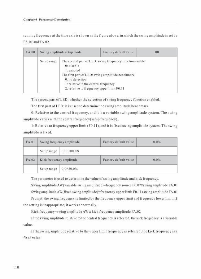
running frequency at the time axis is shown as the figure above, in which the swing amplitude is set by
FA.01 and FA.02.
FA.00 Swing amplitude setup mode Factory default value 00
Setup range The second part of LED: swing frequency function enable
0: disable
1: enabled
The first part of LED: swing amplitude benchmark
0: no detection
1: relative to the central frequency
2: relative to frequency upper limit F0.11
The second part of LED: whether the selection of swing frequency function enabled.
The first part of LED: it is used to determine the swing amplitude benchmark.
0: Relative to the central frequency, and it is a variable swing amplitude system. The swing
amplitude varies with the central frequency(setup frequency).
1: Relative to frequency upper limit (F0.11), and it is fixed swing amplitude system. The swing
amplitude is fixed.
FA.01 Swing frequency amplitude Factory default value 0.0%
Setup range 0.0 100.0%~
FA.02 Kick frequency amplitude Factory default value 0.0%
Setup range 0.0 50.0%~
The parameter is used to determine the value of swing amplitude and kick frequency.
Swing amplitude AW(variable swing amplitude)=frequency source F0.07 swing amplitude FA.01x
Swing amplitude AW(fixed swing amplitude)=frequency upper limit F0.11 swing amplitude FA.01x
Prompt: the swing frequency is limited by the frequency upper limit and frequency lower limit. If
the setting is inappropriate, it works abnormally.
Kick frequency=swing amplitude AW kick frequency amplitude FA.02x
If the swing amplitude relative to the central frequency is selected, the kick frequency is a variable
value.
If the swing amplitude relative to the upper limit frequency is selected, the kick frequency is a
fixed value.
110
Chapter 6 Parameter Description

FA.03 Swing frequency cycle Factory default value 10.0s
Setup range 0.1 3000.0s~
FA.04 Time constant of triangular wave boost Factory default value 50.0%
Setup range 0.1 100.0%~
Swing frequency cycle: It refers to the time of a complete cycle of swing frequency.
FA.04 Time constant of triangular wave boost is relative to FA.03 swing frequency cycle.
Triangular wave boost time= FA.03 FA.04(unit: s)x
Triangular wave falling time= FA.03 (1-FA.04) (unit: s)x
FA.05 Setup length Factory default value 1.000km
Setup range 0 65.535km~
FA.06 Designed length Factory default value 1.000km
Setup range 0 65.535km~
FA.07 Number of pulses each meter Factory default value 100.0
Setup range 0.1 6553.5~
The setup(designed)length, actual length and number of pulses each meter are mainly used for
fixed length control. For the image parameter FV.19 of FA.05 and FA.06, their meanings are the same,
just one method added to easy parameter modification and viewing.(Please refer to the description of
FA.11 exact stop mode).
The length is calculated via the pulse signal input by the X5 input terminal, and it needs to set the
corresponding input terminal to length count input terminal.
Actual length=length count input number of pulsed/number of pulses each meter
When the actual length FV.18 exceeds the setup length FA.05, the output terminal“length arrival
terminal” will output ON signal(refer to Group F4 function code).
Fixed length control as one of the exact stop modes, when it arrivals the setup length, the inverter
stops automatically. For details, refer to the parameter description of FA.11.
111
Chapter 6 Parameter Description

FA.08 Setup counting value Factory default value 1000
Setup range 1 9999~
FA.09 Designated counting value Factory default value 1000
Setup range 1 9999~
Actual counting value FV.16 is calculated via the pulse signal input by the X6 input terminal, and
it needs to set the X6 terminal as count input terminal.
For image parameter FV.17 of FA.08, its meaning is the same, just one method added to easy
parameter modification and viewing.(Please refer to the description of FA.11 exact stop mode).
When the actual counting value reaches the setup counting value, the output terminal will output
signal of setup counting value arrival. The counter will stop counting.
When the actual counting value reaches the designated counting value, the output terminal will
output signal of designated counting value. The counter will continue counting till the “setup counting
value” is reached.
The designated counting value FA.09 shall not exceed the setup counting value FA.08.
The function is shown as the following figure:
1 3 4 5 6 7 8Counting Pulse X5
Setting Count OC
2
Designated Count Relay
Fig.6-22 Schematic diagram for Setup counting value
reference and designated counting value reference
Counter control as one of the exact stop modes, when it arrivals the setup length, the inverter stops
automatically.
For details, refer to the parameter description of FA.11.
FA.10 Internal timing setup running time Factory default value 24.000h
Setup range 0.0 65.535h~
For image parameter FV.21 of FA.10, its meaning is the same, just one method added to easy
parameter modification and viewing.(Please refer to the description of FA.11 exact stop mode).
When actual running time FV.20 exceeds the setup running time FA.10, the output terminal“Setup
running time arrival terminal” will output ON signal(refer to Group F4 function code).
112
Chapter 6 Parameter Description

Timing stop control as one of the exact stop modes, when it arrivals the setup length, the inverter
stops automatically. For details, refer to the parameter description of FA.11.
FA.11 Exact stop mode setup Factory default value 0
Setup range 0 disabled
1 Setup counting value arrival
2 Setup length arrival
3 Setup running time arrival
Exact stop mode: In term of several control produce quantity which is in common use to realize
inverter automatic stopping, and you can use operation panel to replace counter, length controller,
timing which are widely used in machine facilities.
The operation methods of exact stop:
1: Data display and modification
If the parameter is set in reason, the inverter can display and modify the data just like operating
the counter, the length controller and the timing.
Firstly, set the corresponding parameter of exact stop as enabled by setting parameter F6.01 to
F6.04.
e.g. Set F6.02=96 to make the setup length and the actual length enabled.
In the monitor mode of the state parameter, you can switch display content via shift key. When it
switches into display actual length, you can modify it via Increase key/Decrease key of the operation
panel, exit it by pressing FUNC key or ENTER key. The actual length value will increase unceasingly,
on base of modified value, along with the signal input.
When it switches into display setup length, you can modify the setup length via Increase key/
Decrease key of operation panel, exit it by pressing FUNC key or ENTER key. The difference between
FUNC key and ENTER key is described as follows: By pressing ENTER key, the modified content will
be saved to EEPROM so that it is still active when power-on at the next time, while by pressing FUNC
key, the modification of setup length only enabled at this time.
The above examples are also applicable to the modification of counter and timing data.
2: Process data reset
The process data contains actual counting value, actual length and actual running time. Through
setting corresponding parameters, the reset of them can be realized by external terminals(setting
Group F3 parameter) or S key(setting F6.00).
113
Chapter 6 Parameter Description

3: Process data memory when power-off
When power-off, the inverter will save the process data, which contains actual counting value,
actual length and actual running time, to EEPROM, and the data will recover to the value as before
when power-on again so that it can produce continuously.
An example for exact stop action mode(set the counting value as N).
N-1 N N+11 2Counting pulse X5
Running command
Stop command
Group MS Speed Function and Simple PLC FunctionFB
Fig.6-22 Schematic diagram for Exact stop control mode
Simple PLC function is to perform automatic control on the MS frequency logic through a built-
in programmable controller(PLC)of the inverter. It can set running time, running direction and running
frequency so as to meet the process requirements.
The series of inverter can implement 16-segment variable control and has four types of acceleration/
deceleration time for selection.
When the setup PLC completes one cycle, the multifunctional output terminal can output an ON
signal. Refer to F4.00 to F4.01 for details.
When the frequency source selections F0.07, F0.03 and F0.04 are determined as MS speed running
mode, FB.00 to FB.15 shall be set to determine its characteristics.
FB.00 MS speed 0 Factory default value 0.0Hz
Setup range 0.0 frequency upper limit F0.11~
FB.01 MS speed 1 Factory default value 0.0Hz
Setup range 0.0 frequency upper limit F0.11~
FB.02 MS speed 2 Factory default value 0.0Hz
Setup range 0.0 frequency upper limit F0.11~
FB.03 MS speed 3 Factory default value 0.0Hz
Setup range 0.0 frequency upper limit F0.11~
FB.04 MS speed 4 Factory default value 0.0Hz
Setup range 0.0 frequency upper limit F0.11~
114
Chapter 6 Parameter Description

FB.05 MS speed 5 Factory default value 0.0Hz
Setup range 0.0 frequency upper limit F0.11~
FB.06 MS speed 6 Factory default value 0.0Hz
Setup range 0.0 frequency upper limit F0.11~
FB.07 MS speed 7 Factory default value 0.0Hz
Setup range 0.0 frequency upper limit F0.11~
FB.08 MS speed 8 Factory default value 0.0Hz
Setup range 0.0 frequency upper limit F0.11~
FB.09 MS speed 9 Factory default value 0.0Hz
Setup range 0.0 frequency upper limit F0.11~
FB.10 MS speed 10 Factory default value 0.0Hz
Setup range 0.0 frequency upper limit F0.11~
FB.11 MS speed 11 Factory default value 0.0Hz
Setup range 0.0 frequency upper limit F0.11~
FB.12 MS speed 12 Factory default value 0.0Hz
Setup range 0.0 frequency upper limit F0.11~
FB.13 MS speed 13 Factory default value 0.0Hz
Setup range 0.0 frequency upper limit F0.11~
FB.14 MS speed 14 Factory default value 0.0Hz
Setup range 0.0 frequency upper limit F0.11~
FB.15 MS speed 15 Factory default value 0.0Hz
Setup range 0.0 frequency upper limit F0.11~
When the frequency source F0.07, F0.03 and F0.04 are determined as PLC running mode, FB.00
to FB.15, FB.16, FB.17 and FB.18 to FB.41 should be set to determine its characteristics.
115
Chapter 6 Parameter Description

T1 T2 T3 T4 T5 T6 T7
a1 f1a2
a2
f2
f2
d3
a3 f3a4
f4
d5
a5f5
a6
a6
f6
f6
d7
d7
f7
f7
d7
RUN command
PLCcirculationcompletion
PLC phasecompletion
FB.16 PLC running mode Factory default value 00
Setup range The second part of LED: PLC running time unit selection
0: second
1: hour
The first part of LED: PLC action mode
0: stop upon completion of one-time running
1: keep final value upon completion of one-time running
2: constant circulation
The second part of LED: PLC running time unit selection.
It is used to define every segment running time unit of the sixteen segments program.
The first part of LED: PLC action mode
0: Stop upon completion of one-time running
The inverter will automatically stop upon completion of one single cycle, and will not restart until
another running command is given.
Fig.6-24 Stop upon the Completion of one-time running
1: Keep final value upon the completion of one-time running
The inverter will automatically keep the running frequency and direction of last one segment upon
completing one single cycle.
T1 T2 T3 T4 T5 T6 T7
a1 f1 d3
a3 f3a4
f4
d5
a5f5
RUN command
Fig.6-25 Keep final value upon the completion of one-time running
116
Chapter 6 Parameter Description

d1d2
T1
d1
T7
f7
f1
Second time cycle
T6
f6
T5
f5
T4
f4
T3
f3
T2
f2
T1
f1
T7
f7
First time cycle
T6
f6
T5
f5
T4
f4
T3
f3
T2
f2
T1
f1
RUNcommand
STOPcommand
2: Constant circulation
The inverter will automatically start next one cycle upon the completion of one cycle, and will not
stop until stop command is given.
Fig.6-26 Constant circulation
FB.17 PLC power-failure memory selection Factory default value 0
Setup range 0 power failure without memory
1 power failure with memory
PLC power failure with memory means the memory of running phase and frequency of PLC before
power failure.
FB.18 Phase 0 running time Factory default value 0.0s
FB.41 Phase 14/15 running mode Factory default value 0000
As for the above parameters, refer to the description
of parameter table.
Group FC Communication Parameter
The communication protocol of Eh600 accords with the protocol criterion of Modbus. To meet the
application requirements of clients, the protocol added accumulation, check mode and complex command
mode to enrich the programme choice of client. For details, please refer to<<EH600 communication
protocol and description of communication>>.
117
Chapter 6 Parameter Description

Group FD Particular Function
FD.00 Droop control Factory default value 0.0Hz
Setup range 0.0Hz 10.0Hz~
When several inverters drive the same load, different velocity leads to the unbalanced load distribution,
thereby, inverter with higher speed has to carry heavier load. The droop control characteristics can change
the speed droop with the addition of load to balance the load distribution. The parameter is used to adjust the
frequency change value of the inverter with droop velocity.
FD.01 FD.02~ Function reserved Factory default value —
FD.03 Relay break protract Factory default value 0.0s
Setup range 0 1000.0s~
FD.04 Pulse input filter times Factory default value 4
Setup range 1 10~
FD.05 Function reserved Factory default value —
FD.06 Output phase loss protection selection Factory default value 1
Setup range 0: disabled 1: enabled
FD.07 Function reserved Factory default value —
FD.08 Inner fan control Factory default value 0
Setup range 0 Automatic
1 Constant open
0: Automatic
Inner fan switch on-off depends on the environmental temperature and inverter’s working state.
1: Constant open
Inner fan opens all the time when power-on.
FD.09 User password Factory default value 0
Setup range 0 9999~
118
Chapter 6 Parameter Description

FA.11 Exact stop mode setup Factory default value 0
Setup range 0 No operation
1 Restore factory default setup value
2 Clear the fault record
1: The inverter restores all the parameters except the parameters in Group F1 to the factory default
ones.
2: The inverter clears the recent fault records.
Group FV Status Parameter
Function
code
Name Setup range Minimum
unit
Factorydefault value
Modifi-cation
FV.00 Output
frequency
0 frequency upper limit F0.11~ 0.1Hz — *
FV.01 Setup
frequency
(flashes)
0 frequency upper limit F0.11~ 0.1Hz — *
FV.02 Output
current
0.1 1000.0A~ 0.01A — *
FV.03 Running rev 0 9999rpm~ 1r/min — *
FV.04 Setup rev
(flashes)
0 9999rpm~ 1r/min — *
FV.05 Running load
speed
0.001 9999~ 0.001m/S — *
FV.06 Setup load
speed
(flashes)
0.001 9999~ 0.001m/S — *
FV.07 Output
voltage
0 rated voltage~ 1V — *
FV.08 Bus voltage — 1V — *
FV.09 Input AC
voltage
— 1V — *
119
Chapter 6 Parameter Description

Group FV Status Parameter
Function
code
Name Setup range Minimum
unit
Factorydefault value
Modifi-cation
FV.10 AI 0 10.00V Note: when current
inputs: 1V corresponds to 2mA
~ 0.01V — *
FV.11 Function
reserved
— *
FV.12 Pulse
reference
(DI)
0 50.00kHz~ 0.001kHz — *
FV.13 PID setup
(flashes)
0.1% — *
FV.14 PID
feedback
— 0.1% — *
FV.15 Terminal
status
Refer to the following detailed
explanation
— — *
FV.16 Actual
counting
value
0 setup counting value~ 1 0 ○
FV.17 Setup
counting
value
(flashes)
1 9999~ 1 1000 ○
FV.18 Actual
length
0 65.535km~ 0.001km 0.0km ○
FV.19 Setup length
(flashes)
0 65.535km~ 0.001km 1.000km ○
FV.20 Actual
running time
0 65.535h~ 0.001h 0.0h ○
FV.21 Setup
running time
(flashes)
0 65.535h~ 0.001h 24.00h ○
120
Chapter 6 Parameter Description

Group FV Status Parameter
Function
code
Name Setup range Minimum
unit
Factorydefault value
Modifi-cation
FV.22 AO output 0 10.00V~ 0.01V — *
FV.23 Function
reserved
— *
FV.24 Radiator
temperature
— 0.1℃ — *
FV.25 Total running
time
Total running time after leave
factory
1h — *
FV status parameter is used to display the current state of inverter, there are two methods to view it.
As for details, please refer to the method of viewing status parameter in 4.3 section.
FV.16 to FV.21, the control parameter of exact stop, can be modified on-line. As for the modification
and setting, refer to parameter description of FA.11.
121
Chapter 6 Parameter Description

7.1 Fault Alarm and Countermeasures
Inverter Unit Protection
E.1
Check if the output loop of theinverter is grounding or short circuited
Check if there is contactor orother switch parts between inverter
and motor
Whether the cable connectingthe motor with the inverter is toolong
No
No
No
No
No
No
No
Whether the module is over heat
Check if the cable connectionsinside the inverter are loosen
If it works normally after replacingthe main control board
If it works normally after replacingthe drive board
If it works normally after replacingthe inverter module
Performtroubleshooting
Removethe parts
Insert all the connectingcables properly
The main controlboard is faulty
The drive boardis faulty
The invertermodule is damaged
Install a reactoror output filter
Check if the air duct isblocked and if the fan is innormal status , and resolvethe existing problems .
Yes
Yes
Yes
Ask for technical support
Yes
Yes
Yes
Yes
Yes
EH600S inverter has 22 pieces of warning information and protection function. in case of abnormal
fault, the protection function will be invoked, the inverter will stop output, and the faulty relay contact
of the inverter will start, the fault code will be displayed on the display panel of the inverter. Before
consulting the service department, the user can perform self-check according to the prompts of the chapter,
analyze the reason and find out the solution. If the fault is caused by the reasons described in the dotted
frame, please consult the agent or our company directly.
122
Chapter 7 Fault Diagnosis and Solution
Chapter 7 Fault Diagnosis and Solution

E. OC 1
Check if the output loop of theinverter is grounding or short circuited
No
No
No
No
No
No
Whether the acceleration time is too short
Whether the decelerated time is too short
Whether the manual boost torque
or V/F curve is proper
Whether the voltage is too low
Whether the voltage is too low
Whether the rotating motor is started
Whether the load is added suddenly
during the acceleration
Perform troubleshooting
Adjust the manual boost
torque or V/F curve
Adjust the voltageto normal range
Select start upon rotationalvelocity follow-up or startupon motor shutdown
Remove theadded load
Prolong the acceleration time
Yes
Yes
Yes
Yes
Yes
Yes
The inverter modelis rather small
Acceleration over current
Deceleration over current
E. OC 2
No
No
No
No
Install the brake unitand brake resistor
Yes
Yes
Yes
Yes
Yes
Yes
Ask for technical support
Whether the brake unit and brake
resistor are installed
Check if the output loop of theinverter is grounding or short circuited Perform troubleshooting
Prolong the deceleration time
Adjust the voltageto normal range
Remove theadded load
Whether the load is added suddenly
during the acceleration
123
Chapter 7 Fault Diagnosis and Solution

Constant speed over current
E.OC3
Check if the output loop of theinverter is short circuited or hasleakage current
No
No
Whether the load is added suddenly
during the running
Whether the inverter load can be lightened
Perform troubleshooting ,and install output reactorif the cable is too long
Remove the added load
Lighten the load
Yes
Yes
Yes
The inverter modelis rather small
No
Acceleration over voltage
Deceleration over voltage
E. OU1
If the input voltage is too high
If there are external forcesdriving the motor to run during the
acceleration process .
No
No
Adjust the voltageto normal range
Remove the external forces
Yes
Yes
E. OU2
Whether the brake unit and resistor
are installedInstall the brakeunit and resistor
Whether the input voltage is too high
Whether there are external forces
driving the motor to run during the
deceleration process .
No
No
Whether the deceleration time is too short
Adjust the voltageto normal range
Prolong the decelerationtime or install brake unitand resistor
Remove the externalforces or install brakeunit and resistor
Yes
Yes
Yes
No
No
Ask for technical support
Ask for technical support
124
Chapter 7 Fault Diagnosis and Solution

Constant over voltage
Stop over voltage
Whether the input voltage is too high
Whether the input voltage is too high
Whether there are external forces
driving the motor to run during the
running process
No
Adjust the voltageto normal range
Adjust the voltageto normal range
Remove the externalforces or install brakeunit and resistor
Yes
Yes
Yes
No
No
Ask for technical support
Ask for technical support
E
E
.
.
O
O
U
U
3
4
Running under voltage
E.LU
Whether there is transient power failure
Check the rectifier bridgeand buffer resistor are normal
Whether
Detect if the voltage at the inputend of the inverter is within the range
specified by the specifications
No
No
No
Yes
Yes
Yes
Measure if the DC bus voltage is normal
Check the drive board is normalWhether
Check the main controlboard is normal
Whether
Inverter reset
Replace the broken rectifierbridge or buffer resistor
Replace thedrive board
Replace thecontrol board
Adjust electrical source or removeexternal power supply loop fault
Yes
No
No
No
No
Maintainer reference
125
Chapter 7 Fault Diagnosis and Solution

Motor overload
EE
..
OO
LL
12
Whether the motor overload protection
parameter F8.03 is set properly
Whether the load is too heavy or
the motor does not rotate
Yes
Set it properly
Reduce the load andcheck the motor andthe machine
No
Yes
The invertermodel is small
Inverter overload
No
No
No
No
Whether the voltage of power net is too lowAdjust the inputvoltage within theallowable range
Yes
Yes
Yes
Phase loss at the output side
E.LF
Check the cable connecting theinverter to the motor is normal
Whether
Yes
Yes
No
Check the drive board is normalWhether
Check the module is normalWhether
Check the main controlboard is normal
Whether Replace the maincontrol board
Replace thedrive board
Replace themodule
Perform troubleshooting
Check if the three-phasewinding of the motor isnormal and remove the fault
No
No
No
No
Yes
Yes
Ask for technical support
Check the three-phase outputof the running inverter without motor
is balanced
Whether
Whether the deceleration time is too short Prolong thedeceleration time
Whether the manual boost torque or
V/F curve is proper
Adjust the manual boost
torque or V/F curve
126
Chapter 7 Fault Diagnosis and Solution

Inverter overheat
E. O H
Whether the air duct is blocked
No
No
No
No
Whether the thermistor of the module
is broken
Whether the inverter module is broken
Replace thedrive board
Replace theinverter module
Replace the maincontrol board
Replace thethermistor
Clean the air duct
Reduce the ambienttemperature
Yes
Yes
Yes
Yes
Yes
Yes
Yes
Ask for technical support
Whether the ambient temperature is too high
Whether the fan is broken Replace the fan
No
No
External equipment fault
E.EF
it inputs external fault signalvia the multifunctional terminal XWhether Check and remove
the external fault
Yes
Communications fault
E.CE
Whether the host computer is working
Yes
Yes
Yes
Yes
Yes
Whether the baud rate is setting correctly
Whether the carrier wave frequency
F2.12 setup is too high
it is satisfy with the controlneed when communication parameterFC.05 isn’t set as 2
Whether
the communication parameterFC.03 and FC.04 are setting correctlyWhether
Set the baudrate correctly
Modify the communicationparameter
Reduce the carrierwave frequency
Modify the communicationparameter
Check thecable
communication
Check the host computercable connection
No
No
No
No
No
No
Yes
Whether the RS485 communication
cable connection is normal
Ask for technical support
Check the drive board is normalWhether
Check the main controlboard is normal
Whether
127
Chapter 7 Fault Diagnosis and Solution

Output grounding
CPU interference
E.GF
E.2
Replace cableor motor
No
Yes
Yes
Yes
Current detect fault
E.3
Check the sensor and connectis normal
Whether Replace thesensor orconnections
No
No
No
Yes
EEPROM read-write fault
E.4
Yes
Ask for technical support
Ask for technical support
Ask for technical support
Ask for technical support
Check the drive board is normalWhether
The main controlboard is faulty
The main controlboard is faulty
The main controlboard is faulty
Whether it works normally after
replacing the main control board
Whether it works normally after
replacing the main control board
Whether it works normally after
replacing the main control board
Replace thedrive board
Replace the drive board
Check the output is short circuitedWhether
the
128
Chapter 7 Fault Diagnosis and Solution

Check three-phase inputpower supply is normal
Whether
Yes
Yes
Check the drive board is normalWhether
Check the main controlboard is normal
WhetherReplace themain controlboard
Replace thedrive board
Check and resolve the problems in theexternal lines to ensure that the three-phase power input to the inverter isnormal
No
No
No
Ask for technical support
7.2 Common fault and resolution
Phase loss at the input side
E.5
During the using process of inverter, you may encounter the following faults. Please conduct simple
fault analysis by referring to the methods below:
1: No display upon power-on:
1) Use multimeter to measure whether the input power is consistent with the rate voltage of inverter.
If the power is faulty, please perform it.
2) Check whether the rectifier is good, if it is damaged, please ask for technical support.
3) Check whether the start resister is good, if it is good, the fault might be in switching power supply,
please ask for technical support.
2: The operation panel displays the words“CE”upon power-on:
If the communication between keyboard and main control board has something wrong, you need to
check whether the keyboard or main control board or it’s connection is normal.
3: The circuit breaker starts aside after power-on:
1) Check whether the earth terminal E of inverter is grounding reliably and perform the problem.
2) Check whether there is grounding or short circuited things between the input power, please remove
it if there is.
3) Check the rectifier is punctured, if it is, please ask for technical support.whether
4: The motor does not rotate upon inverter running:
1) Whether it has balanceable three-phase output among U and V and W, if it has, there is something
wrong with the motor circuit or it is damaged or the motor blocked for mechanical reasons, please remove
it.
2) There is output but it is not balanceable, the reason might be the drive or module of inverter is
damaged. Please ask for technical supply.
129
Chapter 7 Fault Diagnosis and Solution

3) If there is no output voltage, the reason might be the drive board or output module is damaged.
Please ask for technical supply.
5: The inverter displays normally upon power-on, but the circuit breaker starts aside upon running:
1) Check whether there is double phase short circuit or grounding between the output modules. If
there is, please ask for technical supply.
2) Check whether there is grounding or short circuit things between the motor cables, remove it if
there is.
3) If the trip happens every once in a while and the distance between motor and inverter is too long,
then you may consider to install an AC output reactor.
130
Chapter 7 Fault Diagnosis and Solution

SHENZHEN XILIN ELECTRIC TECHNOLOGIES CO.,LTD.
Add. 3rd Floor,No.B Building ,Huafeng Industrial Zone , Gushu Hangcheng Street , Xixiang Town,
Bao'an District, Shenzhen City,China
:
Warranty Agreement
Tel 0755-29784876 Sell Service Certer 0755-29784875: :
Service Department
Fax 0755-29784873 P.C. 518000: :
1. The warranty period of the product is 18 months(refer to the bar code on the equipment body).
During the warranty period, if the product fails or it is damaged under the condition of normal use by
following the instruction, our company will be responsible for free maintenance.
2. Within the warranty period, maintenance will be charged for the damages caused by the following
reasons:
a: The damage caused by improper use or repair/modification without prior permission;
b: The damage caused by fire, flood, abnormal voltage, other natural disasters and second disaster;
c: The hardware damage caused be artificial falling or transportation after purchase.
d: The damage caused by the improper operation;
e: The damage or failure caused by the trouble out of the equipment(e.g. External device)
3. If there is any failure or damage to the product, please fill in the information of the Product
Warranty Card in details correctly.
4. The maintenance fee is charged according to the newly adjusted Maintenance Price List of our
company.
5. In general, the warranty card will not be re-issued. Please keep the card and present it to the
maintenance personnel when asking for maintenance.
6. If there is any problem during the service, please contact the agent of our company or our company
directly.
7. The interpretation of this agreement shall reside with SHENZHEN XILIN ELECTRIC
TECHNOLOGIES CO., LTD.
SHENZHEN XILIN ELECTRIC TECHNOLOGIES CO.,LTD.

Maintenance personnel:
Failure
information
( :maintenance time and content)
Name of agent:
Body bar code:Product
information
Product model:
Tel.:P.C.:
Name of corporation: Contact person:Customer
information
Add. of corporation:
Product Warranty Card