Embed Size (px)
Citation preview

www.ouman.fi
EH-net
EH-203 Heatingregulator
OUMAN EH-203 is a new generation heating regulator. Its versatility, intelligence and clarity have made it an ideal heating regulator for all kinds of water circulation heating systems.
In addition to heating control, EH-203 has a number of other control and alarm functions for facilities. Measurement information can be read, settings and controls can be checked and adjusted, and alarms can be received and acknowledged remotely via a GSM telephone’s text messages or a web browser. A GSM modem (optional equipment) must be connected to EH-203 to enable GSM use. An EH-net web server (optional equipment) is neededfor web use.
Types of heating systems:• Radiatorheating
• Floorheating
• Airconditioningpreregulation
• Hotwaterregulation
Types of heating production:• Districtheatingexchangers
• Boilerplants
• Accumulators
• Districtheatingsubstations
Remote control options:
• EH-net
Webbaseduserinterface
Internet/Intranet
• GSM Control
Graphicuserinterface
(canbefreelydownloadedat:www.ouman.fi)
TraditionaltextmessageusewithallGSMphones
OUMAN EH-203
2
FOR STARTERSOuman EH-203 is a multifunctional heating controller which is adaptable to many different types of heating systems. Ouman EH-203 has the ability to control two heating circuits and one hot water control circuit simultane-ously. Your controller’s display changes depending on the connections and selected functions that are in use.
All the different functions are presented in this user manual. In the begin-ning we present the basic principles for using the controller.
User panelRegulating circuit codeindicates the regulating circuitin question (heating circuit H1shown here).
Browse button moves the > cursor up and down.
Group select button -moves you from oneregulating to the next.The regulating circuits are:H1, heating regulating circuit,H2, heating regulating circuit andHW, domestic hot water regulating circuit.
Symbols which indicateactuator control mode.
Regulator opens the 3-pointcontrolled actuator.
Regulator closes the 3-point controlled actuator.Height up the pillar shows the position of the voltage controlled actuator.
Valve is fully open (100%) and the control voltage is 10 V.
Valve is fully closed (0%) andthe control voltage is 0 V or 2 V (2 ... 10 V actuator).
Decreasebutton
OKbutton
Increase -buttonWhen you press + button in adjoining basic display mode, the regulator dis-plays all the measure-ment results in turn and then returns to the basic display mode.
INFO-button -givesoperating instructions and additional informa-tion on the display in different situations.
ESC press toreturn to theprevious display.
Remote control options:Remote control via a GSM phone
Most of EH-203’s user level functions can also be carried out via GSM phone text messages.
Web based user interfaceOuman controllers can also be controlled and moni-tored via an inexpensive web user interface. A web scanner is easy to use and can illustrate remote con-trol and monitoring of even large Ouman control sys-tems regardless of the time and place.
Text message use is illustrated on page 20.
If the control circuit has beenlabeled, the control circuit’s current control mode and label are alternately displayed on the top line of the basic display.
OUMAN EH-203 CONTENTS Settings for characteristic heating curve SettingsMeasurementsMeasurements and sensor connection informationSupply water temperature informationDistrict heating energy measurementOperating modesClock functions Language selection Type informationStart functionAlarms GSM-functions
4689101112131616171819
User guide
OUMAN OYVoimatie6,90440KempeleTel.+3584248401Fax+35888155060
www.ouman.fi
Espoo sales office: Upseerinkatu1,02600EspooTel+358424840202Fax+358947801030
4445464748
ServiceEntering the maintenance mode Tuning valuesSettings Trends Actuator selectionRelay 1 control selectionRelay 2 control selection
21222324252627
28293031323435363737383940414243
These pages contain direc-tions for maintenance per-sons authorized by Ouman. Access to the regulator´s maintenance mode is pre-vented by a maintenance mode.
Maintenance guide
Installation and maintenance guideConnection guideOptional equipmentIndexTechnical information
Special serviceRestore factory settingsSettings Measurement 6 setting Pressure measurement Digital inputs 1, 2 and 3 Characteristic heating curve type selection (3-point/5-point)Labelling control circuits Energy meter Net connectionsLON initialization Net measurements Text message connection via the modemText message connection via bussDistrict heating’s return water temperature limitingData linkUsing the browser
We reserve the right to make changes in our products without prior notice.
OUMAN EH-203
4
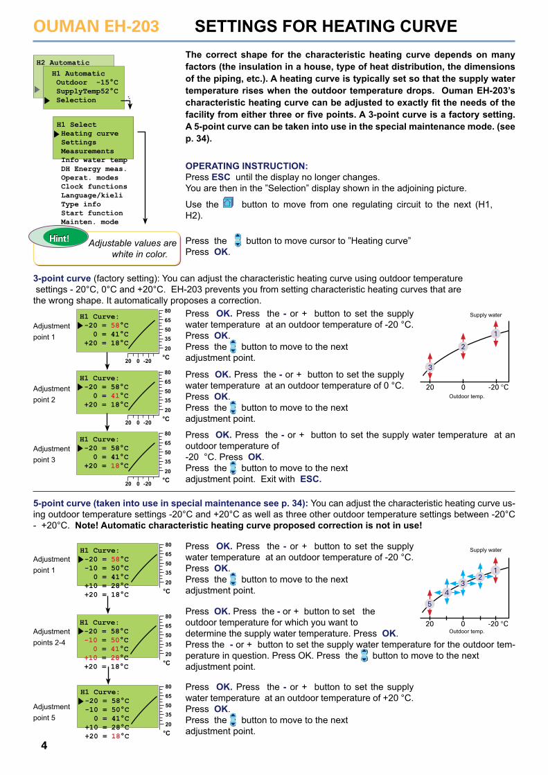
Press OK. Press the - or + button to set the supply water temperature at an outdoor temperature of -20 °C. Press OK. Press the button to move to the next adjustment point.
Press OK. Press the - or + button to set the supply water temperature at an outdoor temperature of -20 °C. Press OK. Press the button to move to the next adjustment point.
Press OK. Press the - or + button to set the outdoor temperature for which you want to determine the supply water temperature. Press OK. Press the - or + button to set the supply water temperature for the outdoor tem-perature in question. Press OK. Press the button to move to the next adjustment point.
Press OK. Press the - or + button to set the supply water temperature at an outdoor temperature of +20 °C. Press OK. Press the button to move to the next adjustment point.
Press OK. Press the - or + button to set the supply water temperature at an outdoor temperature of 0 °C. Press OK. Press the button to move to the next adjustment point.
Press OK. Press the - or + button to set the supply water temperature at an outdoor temperature of -20 °C. Press OK. Press the button to move to the next adjustment point. Exit with ESC.
SETTINGS FOR HEATING CURVE
5
4
2
20 0 -20 °C
3
1
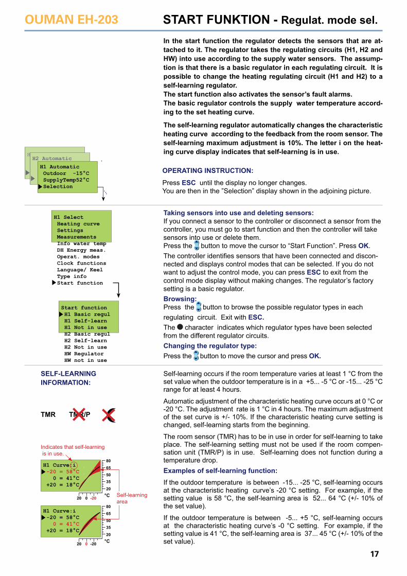
H2 AutomaticH1 Automatic Outdoor -15°C SupplyTemp52°C Selection
H1 Select Heating curve Settings Measurements Info water temp DH Energy meas. Operat. modes Clock functions Language/kieli Type info Start function Mainten. mode
H1 Curve: -20 = 58°C 0 = 41°C +20 = 18°C
°C20
20
35506580
0 -20
H1 Curve: -20 = 58°C -10 = 50°C 0 = 41°C +10 = 28°C +20 = 18°C °C
20
35506580
H1 Curve: -20 = 58°C 0 = 41°C +20 = 18°C
°C20
20
35506580
0 -20
H1 Curve: -20 = 58°C -10 = 50°C 0 = 41°C +10 = 28°C +20 = 18°C °C
20
35506580
H1 Curve: -20 = 58°C 0 = 41°C +20 = 18°C
°C20
20
35506580
0 -20
H1 Curve: -20 = 58°C -10 = 50°C 0 = 41°C +10 = 28°C +20 = 18°C °C
20
35506580
The correct shape for the characteristic heating curve depends on many factors (the insulation in a house, type of heat distribution, the dimensions of the piping, etc.). A heating curve is typically set so that the supply water temperature rises when the outdoor temperature drops. Ouman EH-203’s characteristic heating curve can be adjusted to exactly fit the needs of the facility from either three or five points. A 3-point curve is a factory setting. A 5-point curve can be taken into use in the special maintenance mode. (see p. 34).
OPERATING INSTRUCTION:Press ESC until the display no longer changes.You are then in the ”Selection” display shown in the adjoining picture.
Use the button to move from one regulating circuit to the next (H1, H2).
Press the button to move cursor to ”Heating curve” Press OK.
3-point curve (factory setting): You can adjust the characteristic heating curve using outdoor temperature settings - 20°C, 0°C and +20°C. EH-203 prevents you from setting characteristic heating curves that are the wrong shape. It automatically proposes a correction.
Adjustment point 1
Adjustment point 2
Adjustment point 3
Adjustment point 1
Adjustment points 2-4
Adjustment point 5
3
20 0 -20 °C
2
1
Supply water
Outdoor temp.
5-point curve (taken into use in special maintenance see p. 34): You can adjust the characteristic heating curve us-ing outdoor temperature settings -20°C and +20°C as well as three other outdoor temperature settings between -20°C - +20°C. Note! Automatic characteristic heating curve proposed correction is not in use!
Hint! Adjustable values are white in color.
Hint!
Supply water
Outdoor temp.
OUMAN EH-203
5
Instructions for setting the curve
H1 Curve: -20 = 58°C 0 = 41°C +20 = 18°C
°C20
20
35506580
0 -20
H1 Curve: -20 = 32°C 0 = 27°C +20 = 21°C
°C20
20
35506580
0 -20
H1 Curve: -20 = 62°C 0 = 42°C +20 = 20°C
°C20
20
35506580
0 -20
H1 Curve: -20 = 58°C 0 = 41°C +20 = 18°C
°C20
20
35506580
0 -20
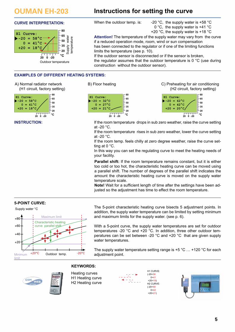
CURVE INTERPRETATION: When the outdoor temp. is: -20 °C, the supply water is +58 °C 0 °C, the supply water is +41 °C +20 °C, the supply water is +18 °CAttention! The temperature of the supply water may vary from the curve if a reduced operation mode, room, wind or sun compensationhas been connected to the regulator or if one of the limiting functionslimits the temperature (see p. 10).If the outdoor sensor is disconnected or if the sensor is broken, the regulator assumes that the outdoor temperature is 0 °C (use during construction without the outdoor sensor).
EXAMPLES OF DIFFERENT HEATING SYSTEMS:
A) Normal radiator network (H1 circuit, factory setting)
B) Floor heating C) Preheating for air conditioning (H2 circuit, factory setting)
INSTRUCTION: If the room temperature drops in sub zero weather, raise the curve setting at -20 °C.If the room temperature rises in sub zero weather, lower the curve setting at -20 °C.If the room temp. feels chilly at zero degree weather, raise the curve set-ting at 0 °C.In this way you can set the regulating curve to meet the heating needs of your facility.Parallel shift: If the room temperature remains constant, but it is either too cold or too hot, the characteristic heating curve can be moved using a parallel shift. The number of degrees of the parallel shift indicates the amount the characteristic heating curve is moved on the supply water temperature scale. Note! Wait for a sufficient length of time after the settings have been ad-justed so the adjustment has time to effect the room temperature.
The 5-point characteristic heating curve bisects 5 adjustment points. In addition, the supply water temperature can be limited by setting minimum and maximum limits for the supply water. (see p. 6).
With a 5-point curve, the supply water temperatures are set for outdoor temperatures -20 °C and +20 °C. In addition, three other outdoor tem-peratures can be set between -20 °C and +20 °C that are given supply water temperatures.
The supply water temperature setting range is +5 °C … +120 °C for each adjustment point.
5-POINT CURVE:Supply water °C
+20
+20°C -20°C
+40
+60
+80
Outdoor temp.
Maximum limit
Minimumlimit
Characteristic heating curve parallel shift
KEYWORDS:
Heating curvesH1 Heating curveH2 Heating curve
H1 CURVE:(-20=58 0=41 +20=19)H2 CURVE:(-20=59 0=42 +20=21)
Sup
ply
wat
er te
mpe
ratu
re
Outdoor temperature
OUMAN EH-203
6
SETTINGS
Settings: Factorysettings:
Explanation: Attention!Range:
Room sensor (TMR) must be con-nected (H1:meas.3, H2: meas. 6, or net). An appropriate room compen-sation ratio for floor heating is usu-ally between 1.5 - 2.0°C.
Transmitter must be connected, the same sensor for regul. circuits H1 and H2 (meas. 6).
Changing the domestic hot water temperature:
Changing the heating regulating circuit setting:
Press the button to move the cursor to the setting that you want to change. Press OK. Press the - or + button to change the setting. Press OK. Exit with ESC.
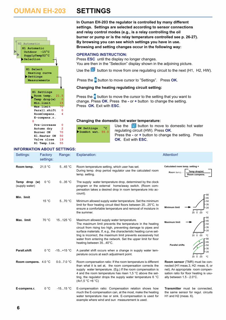
H1 Settings Room temp. 21.5 Temp drop(w) 0 Min.limit 15 Max.limit 70 Parall.shift 0 RoomCompens. 4 E-compens.r. 0 Pre-increase 0 Autumn dry 2 Burner ON 70 El.Heater ON 50 Valve close 19 R1 Temp.lim. 55
H1 Select Heating curve Settings Measurements
HW Settings °C DomHot wat. 55.0
HWH2 Automatic
H1 Automatic Outdoor -15°C SupplyTemp52°C Selection
Room temp.
Temp drop (w) (supply water)
Min. limit
Max. limit
Parall.shift
Room compens.
E-compens.r.
Room temperature setting, which user has set. During temp. drop period regulator use the calculated room temp. setting.
The supply water temperature drop, determined by the clock program or the external home/away switch. (Room com-pensation takes a desired drop in room temperature into ac-count).
Minimum allowed supply water temperature. Set the minimum limit for floor heating circuit tiled floors between 20...25°C, to ensure a comfortable temperature and removal of moisture in the summer.
Maximum allowed supply water temperature.The maximum limit prevents the temperature in the heating circuit from rising too high, preventing damage to pipes and surface materials. If, e.g., the characteristic heating curve set-ting is incorrect, the maximum limit prevents excessively hot water from entering the network. Set the upper limit for floor heating between 35...40°C.
A parallel shift occurs when a change in supply water tem-perature occurs at each adjustment point.
Room compensation ratio: If the room temperature is different than what it is set at, the room compensation corrects the supply water temperature. (Eg.) If the room compensation is 4 and the room temperature has risen 1,5 °C above the set-ting, the regulator drops the supply water temperature 6 °C (4x1,5 °C =6 °C)
E-compensation ratio: Compensation relation shows how much the E-compensation can, at the most, make the heating water temperature rise or sink. E-compensation is used for example where wind and sun measurement is used.
21,5 °C
0 °C
15 °C
70 °C
0 °C
4.0 °C
0 °C
5...45 °C
0...35 °C
5...70 °C
15...125 °C
-15...+15 °C
0.0...7.0 °C
-15...15 °C
In Ouman EH-203 the regulator is controlled by many different settings. Settings are selected according to sensor connections and relay control modes (e.g., is a relay controlling the oil burner or pump or is the relay temperature controlled see p. 26-27).By browsing you can see which settings you have in use. Browsing and setting changes occur in the following way:
Use the button to move to domestic hot water regulating circuit (HW). Press OK.Press the - or + button to change the setting. Press OK. Exit with ESC.
Press the button to move cursor to ”Settings”. Press OK.
INFORMATION ABOUT SETTINGS:
Room compens.Temp drop(w)Room temp. -
8065503520
-20 °C020
Maximum limit
8065503520
-20 °C020
Parallel shifts
8065503520
-20 °C020
Minimum limit
OPERATING INSTRUCTION:Press ESC until the display no longer changes.You are then in the ”Selection” display shown in the adjoining picture.
Use the button to move from one regulating circuit to the next (H1, H2, HW).
Calculated room temp. setting =
OUMAN EH-203
7
Additional information about settings
KEYWORDS:
H1 SettingsH2 SettingsDHW Settings
H1 Settings:Roomtemp.=21.5/Temp drop(w)=0/Min.limit=15/Max.limit=8/Room.compens.=0/Pre increase=2/Autumn dry =2/...
Pre-increase
Autumn dry
Burner ON
El.Heater ON
Valve close
Pump stop
R1 Temp.lim.
DomHot wat.
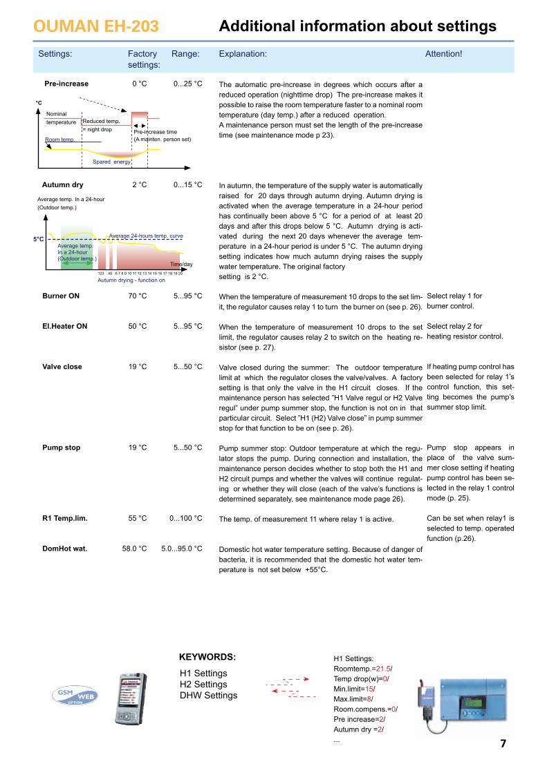
The automatic pre-increase in degrees which occurs after a reduced operation (nighttime drop) The pre-increase makes it possible to raise the room temperature faster to a nominal room temperature (day temp.) after a reduced operation. A maintenance person must set the length of the pre-increase time (see maintenance mode p 23).
In autumn, the temperature of the supply water is automatically raised for 20 days through autumn drying. Autumn drying is activated when the average temperature in a 24-hour period has continually been above 5 °C for a period of at least 20 days and after this drops below 5 °C. Autumn drying is acti-vated during the next 20 days whenever the average tem-perature in a 24-hour period is under 5 °C. The autumn drying setting indicates how much autumn drying raises the supply water temperature. The original factory setting is 2 °C.
When the temperature of measurement 10 drops to the set lim-it, the regulator causes relay 1 to turn the burner on (see p. 26).
When the temperature of measurement 10 drops to the set limit, the regulator causes relay 2 to switch on the heating re-sistor (see p. 27).
Valve closed during the summer: The outdoor temperature limit at which the regulator closes the valve/valves. A factory setting is that only the valve in the H1 circuit closes. If the maintenance person has selected ”H1 Valve regul or H2 Valve regul” under pump summer stop, the function is not on in that particular circuit. Select ”H1 (H2) Valve close” in pump summer stop for that function to be on (see p. 26).
Pump summer stop: Outdoor temperature at which the regu-lator stops the pump. During connection and installation, the maintenance person decides whether to stop both the H1 and H2 circuit pumps and whether the valves will continue regulat-ing or whether they will close (each of the valve’s functions is determined separately, see maintenance mode page 26).
The temp. of measurement 11 where relay 1 is active.
Domestic hot water temperature setting. Because of danger of bacteria, it is recommended that the domestic hot water tem-perature is not set below +55°C.
Select relay 1 for burner control.
Select relay 2 for heating resistor control.
If heating pump control has been selected for relay 1’s control function, this set-ting becomes the pump’s summer stop limit.
Pump stop appears in place of the valve sum-mer close setting if heating pump control has been se-lected in the relay 1 control mode (p. 25). Can be set when relay1 is selected to temp. operated function (p.26).
0 °C
2 °C
70 °C
50 °C
19 °C
19 °C
55 °C
58.0 °C
0...25 °C
0...15 °C
5...95 °C
5...95 °C
5...50 °C
5...50 °C
0...100 °C
5.0...95.0 °C
5°C
Time/day123 45 6 7 8 9 10 11 12 13 14 15 16 17 18 19 20
Autumn drying - function on
Average temp. In a 24-hour(Outdoor temp.)
Nominaltemperature Reduced temp.
= night drop Pre-increase time(A mainten. person set)
Average temp. In a 24-hour(Outdoor temp.)
Spared energy
Room temp.
°C
Average 24-hours temp. curve
Settings: Factorysettings:
Explanation: Attention!Range:
OUMAN EH-203
8
Browsing through measurements:Press the button to browse different measurements.Press ESC to exit from the measurements display.
Every sensor has it’s own typical range. (Eg. outdoor sensor 50...+ 50 °C). If the sensor’s measured value is outside of this range, a - or + character will appear on the measurements display in place of the sensor’s measured value to indicate whether the value is above or below the range.
If there is a sensor defect the regulator gives an alarm (see p. 18) and “err” will appear in place of the measured value.
MEASUREMENTS
KEYWORD:Measurements H1 Supply=52/ H1 Room=21.2/ H1 Ret.water=28/ Outdoor=-15/ H2 Supply=48/...
Measurements
Name change Meas. 6 Give new label
easurements °C H1 Supply H1 Room H1 Ret.water Outdoor H2 Supply Cold water HW Supply HWcircul.wat H2 Return DH ReturnHE3 DH ReturnHE2 DH m3 Inst. l/s DH MWh Inst. kW Wat m3 ActuatorH1 ActuatorH2 ActuatorHW
5221,2
28-15485
5547263430
2001584,666
10036,5145,3
11123,4545%45%45%
Name change Meas. 6 a
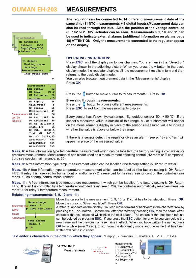
The regulator can be connected to 14 different measurement data at the same time (11 NTC measurements + 3 digital inputs).Measurement data can also be read through the bus. Also the position of the voltage controlled (0...10V or 2...10V) actuator can be seen. Measurements 6, 9, 10, and 11 can be used to indicate external alarms (additional information on alarms page 18) ATTENTION! Only the measurements connected to the regulator appear on the display.
OPERATING INSTRUCTION:Press ESC until the display no longer changes. You are then in the ”Selection” display shown in the adjoining picture. When you press the + button in the basic display mode, the regulator displays all the measurement results in turn and then returns to the basic display mode.You can also browse measurement data in the ”Measurements” displayPress OK.
Press the button to move cursor to “Measurements”. Press OK.
Meas. 6: A free information type temperature measurement which can be labelled (the factory setting is cold water) or pressure measurement. Measurement 6 can alsoor used as a measurement effecting control (H2 room or E-compensa-tion, see special maintenance, p. 30).
Meas. 9: A free information type temp. measurement which can be labelled (the factory setting is H2 return water).
Meas. 10: A free information type temperature measurement which can be labelled (the factory setting is DH Return HE3). If relay 1 is reserved for burner control and/or relay 2 is reserved for heating resistor control, the controller uses meas. 10 as a temp. control measurement.
Meas. 11: A free information type temperature measurement which can be labelled (the factory setting is DH Return HE2). If relay 1 is controlled by a temperature controlled relay (see p. 26), the controller automatically reserves measure-ment 11 for relay 1 temperature measurement. Relabeling measurements 6, 9, 10 and 11:
Move the cursor to the measurement (6, 9, 10 or 11) that has to be relabeled. Press OK. Move the cursor to “Give new label”. Press OK.A letter “a” appears on the display. You can move forward or backward in the character row by pressing the + or - button. Confirm the letter/character by pressing OK, then the same letter/character that you selected will blink in the next space. The character that has been fed last can be deleted by pressing ESC. If you press the ESC button for a while you can delete the new name and the previous name remains in effect. When you have written the name, press OK for a while (over 2 sec.), to exit from the data entry mode and the name that has been written will come into effect.
Text editor’s characters in the order in which they appear: “Empty” . - numbers 0... 9 letters A ...Z a … z ä ö å
Swimming poolCellarSaunaAccumulator
Measurementcan be labelled
H1 Select Heating curve Settings Measurements Info water temp
HWH2 Automatic
H1 Automatic Outdoor -15°C SupplyTemp52°C Selection
OUMAN EH-203
9
MEASUREMENTS Additional information
Strip connector
Measurement Information om mätning: Measurement information:
Attention!
°C-30-25-20-15-10-505
1015202530354045505560657075
177 210130 54097 14072 99055 35042 34032 66025 40019 90015 71012 49010 0008 0556 5315 3254 3683 6022 9872 4882 0841 7531 482
Ω
Resistance value table
1 2 3 4 5
6 6 6 6
7 8
9
10
11
Can be read through the net.
Can be read through the net.
Interchangeable (p. 30). If several compens. are need-ed, the data must be read through the net (p. 36).
Relay 1 controls the burner and relay 2 controls the heating resistor.
Consumption data can be read as digital inputs or through the net.
Appears only when using a 0...10V (2...10V) controlled actuator.
-50... +50 0...+130-10... +80 0...+130 0...+130
-10... +80
ks. 31 ks. 30
0...+130
-10... +80
0...+130
0...+130
0...+130
0...9999999.90.0...120.0
0.0...99999.90...3276,7
0.0...99999.9
INSTRUCTIONS FOR CONNECTING SENSORS:
Outdoor temp. sensor
H1 Supply water sensor
H1 Room sensor
H1 Return water sensor
H2 Supply water sensor
Free temp. measurement(Cold water)
HW supply water sensor HW circul. water sensor(anticipate -sensor)
Free temp.measurement(DH Return HE3)Free temp.measurement(DH Return HE2)Free temp.measurement(Meas. 11)
12
34
56
78
910
11
2x0,8 T1
2x0,8 T2
2x0,8 T3
2x0,8 T4
2x0,8 T5
2x0,8 T6
2x0,8 T7
2x0,8 T8
2x0,8 T9
2x0,8
T10
2x0,8
T11
TMO Meas.1
Meas. 2
Meas. 3
Meas. 4
Meas. 5
Meas. 6
Meas. 7
Meas. 8
Meas. 9
Meas. 10
Meas. 11
TMR
TMW / TMS
TMW / TMS
TMW / TMS
0...10V
TMW / TMS
TMW / TMS
TMW / TMS
TMW / TMS
TMW / TMS
TMW / TMS/
PUTTING SENSOR INTO USE AND REMOVING IT FROM USE:If the outdoor sensor is not connected, the regulator assumes that the outdoor temperature is 0°C and a sensor fault message appears on the display (Outdoor temp err). When the outdoor sensor is connected, the regulator automatically takes it into use. After adding other sensors you must go to start function! (See page 17)
Out temp. H1 SupplyH1 RoomH1 Ret.waterH2 Supply
Cold waterH2 Room E-comp.meas.Network pressure
HW supply HW circul.wat
H2 Return
DH ReturnHE3
DH ReturnHE2
DH m3Inst. l/sDH Mwh Inst. KW Wat m3
Actuator H1Actuator H2Actuator HW
Outdoor temperature Supply water temperature in regulating circuit H1 Room temp. in regulating circuit H1 (room comp.) Return water temperature in regulating circuit H1 Supply water temperature in regulating circuit H2 Free measurement; name using the text editorRoom temp. in regulating circuit H2 (room comp.) E-compensations meas. data (% of the sensors meas. area)Pressure in the heating network
HW (domestic hot water) supply water temp. Temp. of HW return water in heat exchanger.(an anticip. sensor is used in the HW heatexchanger to improve the setting results)
Free measurement; name using the text editor Free temperature measurement that can belabelled or a measurement that controls the burnerand/or heating resistor.
Free measurement; name using the text editor Measured consumption of DH water (m3)Momentary district heating water consumption (l/s)Measured energy consump. of DH water (MWh)DH energy consumption in kW (5 min. period) Measured water consumption of facility (m3) Actuator position in regulating circuit H1 Actuator position in regulating circuit H2 Actuator position in regulating circuit HW
OUMAN EH-203
10
SUPPLY WATER INFORMATION
KEYWORDS:H1 Info waterH2 Info water
H1 SUPPLY TEMP:Follow curve 35.5/Autumn dry 4/OutdoorDelay .=-2/Max lim.eff.=0/Min lim.eff.=0/Result=37.5
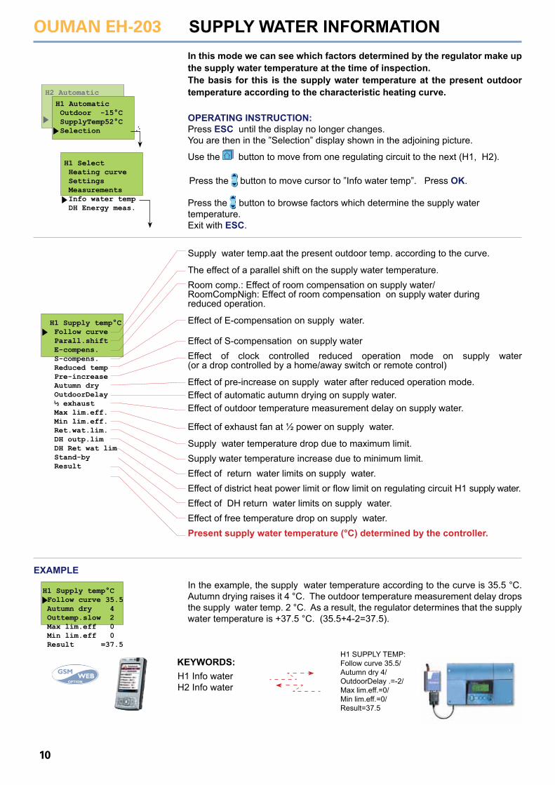
H1 Supply temp°C Follow curve Parall.shift E-compens. S-compens. Reduced temp Pre-increase Autumn dry OutdoorDelay ½ exhaust Max lim.eff. Min lim.eff. Ret.wat.lim. DH outp.lim DH Ret wat lim Stand-by Result
H1 Supply temp°C Follow curve 35.5 Autumn dry 4 Outtemp.slow 2 Max lim.eff 0 Min lim.eff 0 Result =37.5
In this mode we can see which factors determined by the regulator make up the supply water temperature at the time of inspection. The basis for this is the supply water temperature at the present outdoor temperature according to the characteristic heating curve.
EXAMPLEIn the example, the supply water temperature according to the curve is 35.5 °C. Autumn drying raises it 4 °C. The outdoor temperature measurement delay drops the supply water temp. 2 °C. As a result, the regulator determines that the supply water temperature is +37.5 °C. (35.5+4-2=37.5).
Supply water temp.aat the present outdoor temp. according to the curve.
The effect of a parallel shift on the supply water temperature.Room comp.: Effect of room compensation on supply water/RoomCompNigh: Effect of room compensation on supply water during reduced operation.
Effect of E-compensation on supply water.
Effect of S-compensation on supply waterEffect of clock controlled reduced operation mode on supply water (or a drop controlled by a home/away switch or remote control)
Effect of pre-increase on supply water after reduced operation mode.Effect of automatic autumn drying on supply water.Effect of outdoor temperature measurement delay on supply water.
Effect of exhaust fan at ½ power on supply water.
Supply water temperature drop due to maximum limit.Supply water temperature increase due to minimum limit.Effect of return water limits on supply water.Effect of district heat power limit or flow limit on regulating circuit H1 supply water.Effect of DH return water limits on supply water.Effect of free temperature drop on supply water.Present supply water temperature (°C) determined by the controller.
H1 Select Heating curve Settings Measurements Info water temp DH Energy meas.
H2 Automatic
H1 Automatic Outdoor -15°C SupplyTemp52°C Selection
Press the button to browse factors which determine the supply watertemperature. Exit with ESC.
Press the button to move cursor to ”Info water temp”. Press OK.
OPERATING INSTRUCTION:Press ESC until the display no longer changes.You are then in the ”Selection” display shown in the adjoining picture.
Use the button to move from one regulating circuit to the next (H1, H2).
OUMAN EH-203
11
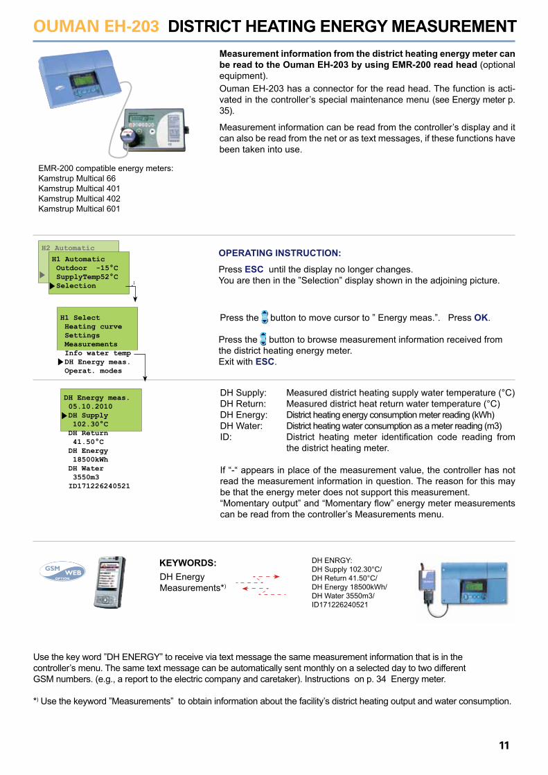
DH Energy meas. 05.10.2010 DH Supply 102.30°C DH Return 41.50°C DH Energy 18500kWh DH Water 3550m3 ID171226240521
DISTRICT HEATING ENERGY MEASUREMENT
KEYWORDS:DH EnergyMeasurements*)
DH ENRGY: DH Supply 102.30°C/ DH Return 41.50°C/ DH Energy 18500kWh/ DH Water 3550m3/ ID171226240521
Measurement information from the district heating energy meter can be read to the Ouman EH-203 by using EMR-200 read head (optional equipment).
EMR-200 compatible energy meters:Kamstrup Multical 66Kamstrup Multical 401Kamstrup Multical 402Kamstrup Multical 601
DH Supply: Measured district heating supply water temperature (°C)DH Return: Measured district heat return water temperature (°C)DH Energy: District heating energy consumption meter reading (kWh)DH Water: District heating water consumption as a meter reading (m3)ID: District heating meter identification code reading from the district heating meter.
If “-“ appears in place of the measurement value, the controller has not read the measurement information in question. The reason for this may be that the energy meter does not support this measurement.“Momentary output” and “Momentary flow” energy meter measurements can be read from the controller’s Measurements menu.
Use the key word ”DH ENERGY” to receive via text message the same measurement information that is in the controller’s menu. The same text message can be automatically sent monthly on a selected day to two different GSM numbers. (e.g., a report to the electric company and caretaker). Instructions on p. 34 Energy meter.
*) Use the keyword ”Measurements” to obtain information about the facility’s district heating output and water consumption.
Ouman EH-203 has a connector for the read head. The function is acti-vated in the controller’s special maintenance menu (see Energy meter p. 35).
Measurement information can be read from the controller’s display and it can also be read from the net or as text messages, if these functions have been taken into use.
H1 Select Heating curve Settings Measurements Info water temp DH Energy meas. Operat. modes
H2 Automatic
H1 Automatic Outdoor -15°C SupplyTemp52°C Selection
Press the button to browse measurement information received from the district heating energy meter. Exit with ESC.
Press the button to move cursor to ” Energy meas.”. Press OK.
OPERATING INSTRUCTION:
Press ESC until the display no longer changes.You are then in the ”Selection” display shown in the adjoining picture.
OUMAN EH-203
12
HW Operat.modes Automatic oper. No temp. incr. Contin.incr. Manual mech. Manual electr.
Manual electr. Control --- Position: 39%
Operat. modes
row 13Działający tryb
row 386O1 Tryby pracy
OPERATING MODES Each regulating circuit can be controlled with the operating modes mentioned below. The factory set automatic regulation is a normal regulating situation in which the clock controlled temperature drops are also possible.
The selected operating mode always appears on the basic display on the top line.
Press the button to move cursor to “Operat. modes”. Press OK.
Press the button to browse operating modes. The character indicates which operating mode has been selected.
Changing operating mode: Move the cursor to the operating mode that you want. Press OK. Exit with ESC.
Manual operation of actuator mechanically: No electricity to actuator.Only mechanical manual operation of actuator is possible.
Manual operation of actuator electrically: Press OK.Press the - or + button to change the position of the actuator.The direction the actuator is being run can be seen from the display.The position’s %-reading indicates the actuator`s position if a voltage controlled 0...10V or 2...10V actuator (0% = closed, 100% = open) isbeing used. Confirm the actuator position by pressing OK.The valve can also be connected so that 100% is closed.
Operating modes in domestic hot water regulating circuit (HW):Press the button to move to the HW circuit. “No temp. incr.” and “Contin. incr.” can be selected from control modes after the amount of temperature increase has been given in maintenance mode settings (See p. 23 “HW increase”).
Additional information about operating modes in heating regulating circuits H1 and H2:
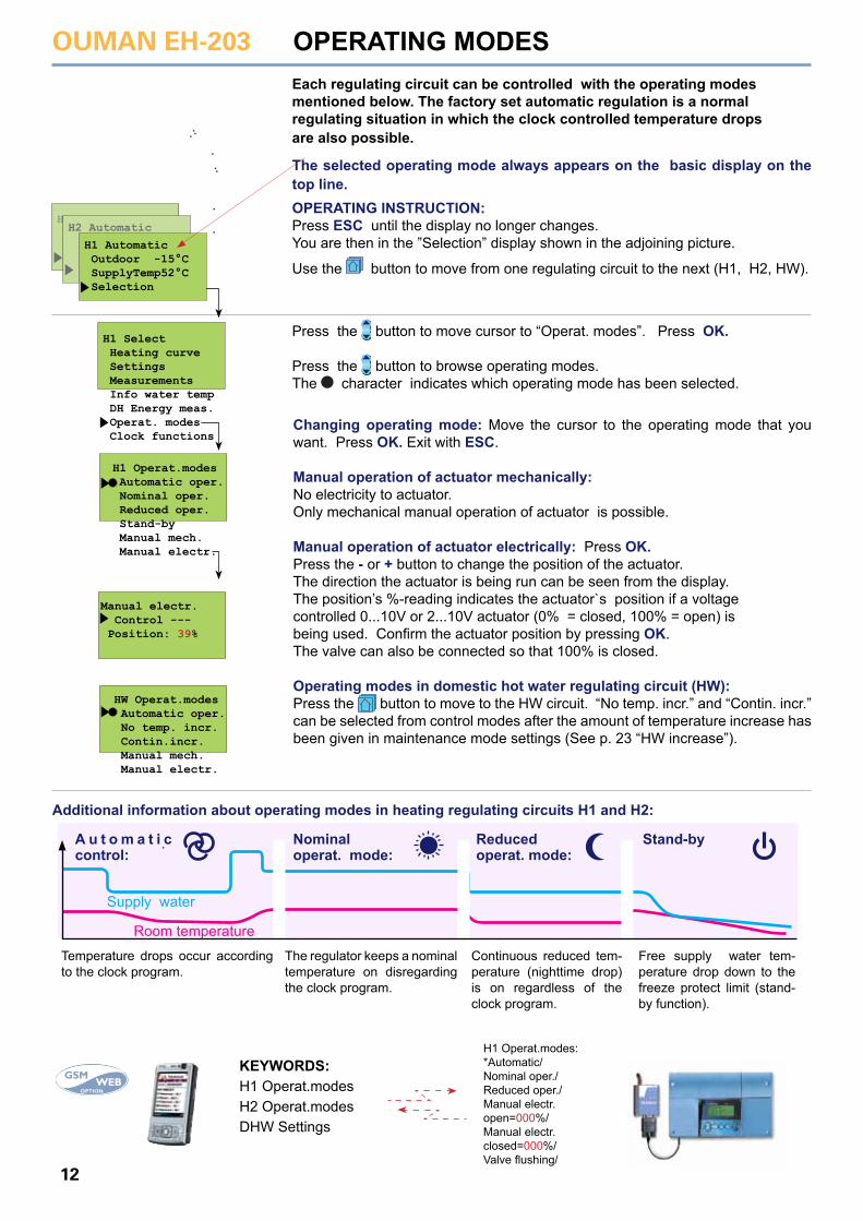
A u t o m a t i c control:
Nominal operat. mode:
Reduced operat. mode:
Stand-by
Room temperature
Supply water
Temperature drops occur according to the clock program.
The regulator keeps a nominal temperature on disregarding the clock program.
Continuous reduced tem-perature (nighttime drop) is on regardless of the clock program.
Free supply water tem-perature drop down to the freeze protect limit (stand-by function).
KEYWORDS:H1 Operat.modesH2 Operat.modesDHW Settings
H1 Operat.modes:*Automatic/Nominal oper./Reduced oper./Manual electr.open=000%/Manual electr.closed=000%/Valve flushing/
H1 Operat.modes Automatic oper. Nominal oper. Reduced oper. Stand-by Manual mech. Manual electr.
H1 Select Heating curve Settings Measurements Info water temp DH Energy meas. Operat. modes Clock functions
OPERATING INSTRUCTION:Press ESC until the display no longer changes.You are then in the ”Selection” display shown in the adjoining picture.
Use the button to move from one regulating circuit to the next (H1, H2, HW).
HWH2 Automatic
H1 Automatic Outdoor -15°C SupplyTemp52°C Selection
OUMAN EH-203
13
Time/ Date 15:45 hr:min 29/03 da/mo 2012 Thursday
Time/ Date 15:45 hr:min 29/03 da/mo 2012 Thursday
Time/ Date 15:45 hr:min 29/03 da/mo 2012 Thursday
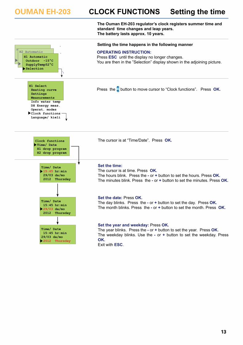
CLOCK FUNCTIONS Setting the timeThe Ouman EH-203 regulator’s clock registers summer time and standard time changes and leap years. The battery lasts approx. 10 years.
The cursor is at “Time/Date”. Press OK.
Set the time: The cursor is at time. Press OK.The hours blink. Press the - or + button to set the hours. Press OK.The minutes blink. Press the - or + button to set the minutes. Press OK.
Set the date: Press OK.The day blinks. Press the - or + button to set the day. Press OK.The month blinks. Press the - or + button to set the month. Press OK.
Set the year and weekday: Press OK.The year blinks. Press the - or + button to set the year. Press OK.The weekday blinks. Use the - or + button to set the weekday. Press OK.Exit with ESC.
Clock functions Time/ Date H1 drop program H2 drop program
Setting the time happens in the following manner
H1 Select Heating curve Settings Measurements Info water temp DH Energy meas. Operat. modes Clock functions Language/ kieli
HWH2 Automatic
H1 Automatic Outdoor -15°C SupplyTemp52°C Selection
Press the button to move cursor to “Clock functions”. Press OK.
OPERATING INSTRUCTION:Press ESC until the display no longer changes.You are then in the ”Selection” display shown in the adjoining picture.
OUMAN EH-203
14
00:00 IncrOnHW _ _ _ _ _ _ _ 00:00 Incr Off _ _ _ _ _ _ _
19:30 DropOnH1 _ _ _ _ _ _ _ 00:00 Drop Off _ _ _ _ _ _ _
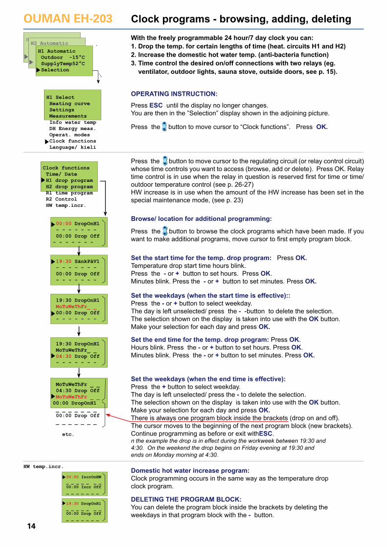
Clock programs - browsing, adding, deletingWith the freely programmable 24 hour/7 day clock you can:1. Drop the temp. for certain lengths of time (heat. circuits H1 and H2)2. Increase the domestic hot water temp. (anti-bacteria function)3. Time control the desired on/off connections with two relays (eg. ventilator, outdoor lights, sauna stove, outside doors, see p. 15).
DELETING THE PROGRAM BLOCK:You can delete the program block inside the brackets by deleting the weekdays in that program block with the - button.
Domestic hot water increase program:Clock programming occurs in the same way as the temperature drop clock program.
Clock functions Time/ Date H1 drop program H2 drop program R1 time program R2 Control HW temp.incr.
00:00 DropOnH1 - - - - - - - 00:00 Drop Off - - - - - - -
19:30 SänkPåV1 - - - - - - - 00:00 Drop Off - - - - - - -
19:30 DropOnH1 MoTuWeThFr_ _ 00:00 Drop Off - - - - - - -
19:30 DropOnH1 MoTuWeThFr_ _ 04:30 Drop Off - - - - - - -
MoTuWeThFr _ _ 04:30 Drop Off MoTuWeThFr _ _00:00 DropOnH1 _ _ _ _ _ _ _ 00:00 Drop Off _ _ _ _ _ _ _
etc.
Press the button to move cursor to the regulating circuit (or relay control circuit) whose time controls you want to access (browse, add or delete). Press OK. Relay time control is in use when the relay in question is reserved first for time or time/outdoor temperature control (see p. 26-27)HW increase is in use when the amount of the HW increase has been set in the special maintenance mode, (see p. 23)
Browse/ location for additional programming:
Press the button to browse the clock programs which have been made. If you want to make additional programs, move cursor to first empty program block.
Set the start time for the temp. drop program: Press OK.Temperature drop start time hours blink.Press the - or + button to set hours. Press OK.Minutes blink. Press the - or + button to set minutes. Press OK.
Set the weekdays (when the start time is effective)::Press the - or + button to select weekday.The day is left unselected/ press the - -button to delete the selection.The selection shown on the display is taken into use with the OK button.Make your selection for each day and press OK.
Set the end time for the temp. drop program: Press OK.Hours blink. Press the - or + button to set hours. Press OK.Minutes blink. Press the - or + button to set minutes. Press OK.
Set the weekdays (when the end time is effective): Press the + button to select weekday.The day is left unselected/ press the - to delete the selection.The selection shown on the display is taken into use with the OK button.Make your selection for each day and press OK. There is always one program block inside the brackets (drop on and off).The cursor moves to the beginning of the next program block (new brackets).Continue programming as before or exit withESC.n the example the drop is in effect during the workweek between 19:30 and 4:30. On the weekend the drop begins on Friday evening at 19:30 and ends on Monday morning at 4:30.
HW temp.incr.
H1 Select Heating curve Settings Measurements Info water temp DH Energy meas. Operat. modes Clock functions Language/ kieli
HWH2 Automatic
H1 Automatic Outdoor -15°C SupplyTemp52°C Selection
Press the button to move cursor to “Clock functions”. Press OK.
OPERATING INSTRUCTION:
Press ESC until the display no longer changes.You are then in the ”Selection” display shown in the adjoining picture.
OUMAN EH-203
15
Clock functions Time/ Date H1 drop program H2 drop program R1 time program R2 Control HW temp.incr.
R1 Styrning Tidstyrning Ständig ON Ständig OFF Timer ON 0 m Timer OFF 0 m
Clock functions; relay control
I display:
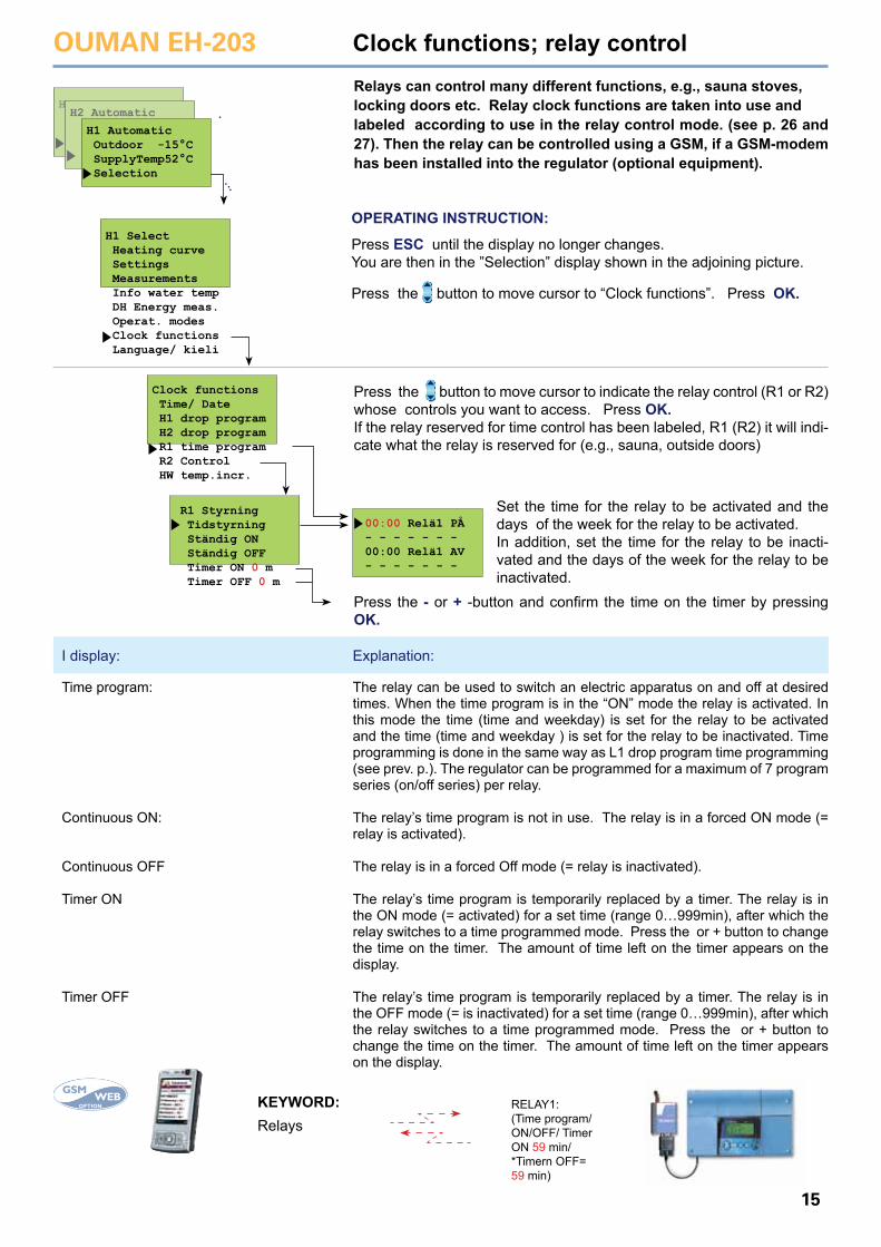
Relays can control many different functions, e.g., sauna stoves, locking doors etc. Relay clock functions are taken into use and labeled according to use in the relay control mode. (see p. 26 and 27). Then the relay can be controlled using a GSM, if a GSM-modem has been installed into the regulator (optional equipment).
Press the button to move cursor to indicate the relay control (R1 or R2) whose controls you want to access. Press OK.If the relay reserved for time control has been labeled, R1 (R2) it will indi-cate what the relay is reserved for (e.g., sauna, outside doors)
00:00 Relä1 PÅ - - - - - - - 00:00 Relä1 AV - - - - - - -
Set the time for the relay to be activated and the days of the week for the relay to be activated.In addition, set the time for the relay to be inacti-vated and the days of the week for the relay to be inactivated.
Press the - or + -button and confirm the time on the timer by pressing OK.
The relay can be used to switch an electric apparatus on and off at desired times. When the time program is in the “ON” mode the relay is activated. In this mode the time (time and weekday) is set for the relay to be activated and the time (time and weekday ) is set for the relay to be inactivated. Time programming is done in the same way as L1 drop program time programming (see prev. p.). The regulator can be programmed for a maximum of 7 program series (on/off series) per relay.
The relay’s time program is not in use. The relay is in a forced ON mode (= relay is activated).
The relay is in a forced Off mode (= relay is inactivated).
The relay’s time program is temporarily replaced by a timer. The relay is in the ON mode (= activated) for a set time (range 0…999min), after which the relay switches to a time programmed mode. Press the or + button to change the time on the timer. The amount of time left on the timer appears on the display.
The relay’s time program is temporarily replaced by a timer. The relay is in the OFF mode (= is inactivated) for a set time (range 0…999min), after which the relay switches to a time programmed mode. Press the or + button to change the time on the timer. The amount of time left on the timer appears on the display.
Time program:
Continuous ON:
Continuous OFF
Timer ON
Timer OFF
RelaysKEYWORD:
Explanation:
RELAY1:(Time program/ON/OFF/ TimerON 59 min/*Timern OFF=59 min)
H1 Select Heating curve Settings Measurements Info water temp DH Energy meas. Operat. modes Clock functions Language/ kieli
HWH2 Automatic
H1 Automatic Outdoor -15°C SupplyTemp52°C Selection
Press the button to move cursor to “Clock functions”. Press OK.
OPERATING INSTRUCTION:
Press ESC until the display no longer changes.You are then in the ”Selection” display shown in the adjoining picture.
OUMAN EH-203
16
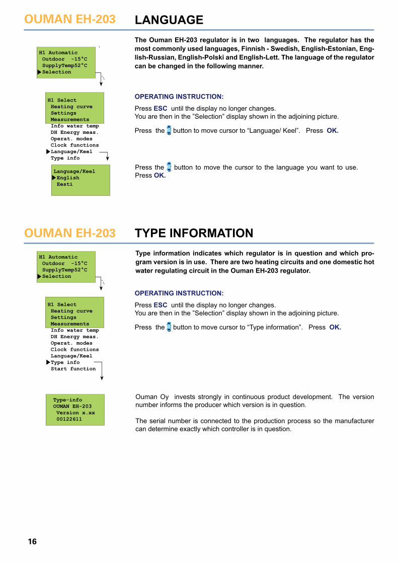
Type-info OUMAN EH-203 Version x.xx 00122611
Language/Keel English Eesti
LANGUAGE
TYPE INFORMATIONOUMAN EH-203
The Ouman EH-203 regulator is in two languages. The regulator has the most commonly used languages, Finnish - Swedish, English-Estonian, Eng-lish-Russian, English-Polski and English-Lett. The language of the regulator can be changed in the following manner.
Press the button to move the cursor to the language you want to use. Press OK.
Type information indicates which regulator is in question and which pro-gram version is in use. There are two heating circuits and one domestic hot water regulating circuit in the Ouman EH-203 regulator.
Ouman Oy invests strongly in continuous product development. The version number informs the producer which version is in question.
The serial number is connected to the production process so the manufacturer can determine exactly which controller is in question.
H1 Select Heating curve Settings Measurements Info water temp DH Energy meas. Operat. modes Clock functions Language/Keel Type info
H1 Select Heating curve Settings Measurements Info water temp DH Energy meas. Operat. modes Clock functions Language/Keel Type info Start function
H1 Automatic Outdoor -15°C SupplyTemp52°C Selection
H1 Automatic Outdoor -15°C SupplyTemp52°C Selection
Press the button to move cursor to “Language/ Keel”. Press OK.
Press the button to move cursor to “Type information”. Press OK.
OPERATING INSTRUCTION:
Press ESC until the display no longer changes.You are then in the ”Selection” display shown in the adjoining picture.
OPERATING INSTRUCTION:
Press ESC until the display no longer changes.You are then in the ”Selection” display shown in the adjoining picture.
OUMAN EH-203
17
START FUNKTION - Regulat. mode sel.
In the start function the regulator detects the sensors that are at-tached to it. The regulator takes the regulating circuits (H1, H2 and HW) into use according to the supply water sensors. The assump-tion is that there is a basic regulator in each regulating circuit. It is possible to change the heating regulating circuit (H1 and H2) to a self-learning regulator.The start function also activates the sensor’s fault alarms.The basic regulator controls the supply water temperature accord-ing to the set heating curve.
The self-learning regulator automatically changes the characteristic heating curve according to the feedback from the room sensor. The self-learning maximum adjustment is 10%. The letter i on the heat-ing curve display indicates that self-learning is in use.
H1 Select Heating curve Settings Measurements Info water temp DH Energy meas. Operat. modes Clock functions Language/ Keel Type info Start function
Start function H1 Basic regul H1 Self-learn H1 Not in use H2 Basic regul H2 Self-learn H2 Not in use HW Regulator HW not in use
Taking sensors into use and deleting sensors: If you connect a sensor to the controller or disconnect a sensor from the controller, you must go to start function and then the controller will take sensors into use or delete them. Press the button to move the cursor to “Start Function”. Press OK.The controller identifies sensors that have been connected and discon-nected and displays control modes that can be selected. If you do not want to adjust the control mode, you can press ESC to exit from the control mode display without making changes. The regulator’s factory setting is a basic regulator.Browsing: Press the button to browse the possible regulator types in eachregulating circuit. Exit with ESC. The character indicates which regulator types have been selected from the different regulator circuits.Changing the regulator type:Press the button to move the cursor and press OK.
Self-learning occurs if the room temperature varies at least 1 °C from the set value when the outdoor temperature is in a +5... -5 °C or -15... -25 °C range for at least 4 hours.
Automatic adjustment of the characteristic heating curve occurs at 0 °C or -20 °C. The adjustment rate is 1 °C in 4 hours. The maximum adjustment of the set curve is +/- 10%. If the characteristic heating curve setting is changed, self-learning starts from the beginning.
The room sensor (TMR) has to be in use in order for self-learning to take place. The self-learning setting must not be used if the room compen-sation unit (TMR/P) is in use. Self-learning does not function during a temperature drop.Examples of self-learning function:If the outdoor temperature is between -15... -25 °C, self-learning occurs at the characteristic heating curve’s -20 °C setting. For example, if the setting value is 58 °C, the self-learning area is 52... 64 °C (+/- 10% of the set value).
If the outdoor temperature is between -5... +5 °C, self-learning occurs at the characteristic heating curve’s -0 °C setting. For example, if the setting value is 41 °C, the self-learning area is 37... 45 °C (+/- 10% of the set value).
TMR TMR/P
Indicates that self-learning is in use.
H1 Curve:i -20 = 58°C 0 = 41°C +20 = 18°C
°C20
20
35506580
0 -20
H1 Curve:i -20 = 58°C 0 = 41°C +20 = 18°C
°C20
20
35506580
0 -20 Self-learning area
SELF-LEARNING INFORMATION:
HWH2 Automatic
H1 Automatic Outdoor -15°C SupplyTemp52°C Selection
OPERATING INSTRUCTION:
Press ESC until the display no longer changes.You are then in the ”Selection” display shown in the adjoining picture.
OUMAN EH-203
18
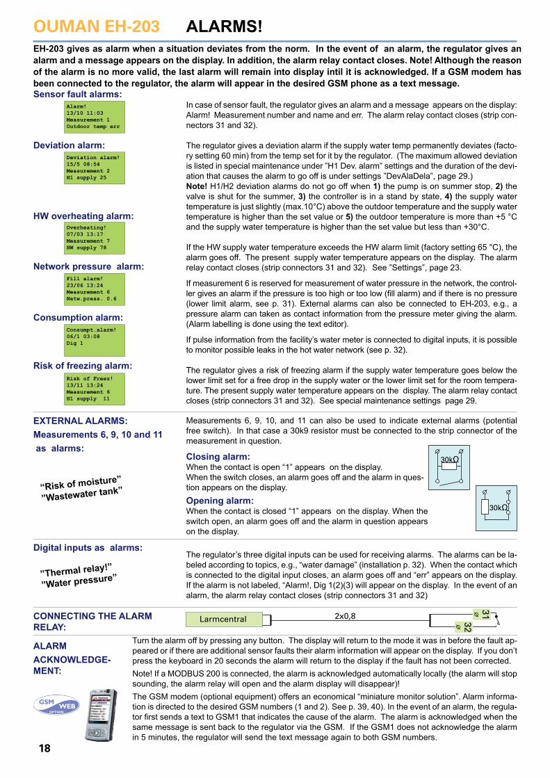
ALARMS!EH-203 gives as alarm when a situation deviates from the norm. In the event of an alarm, the regulator gives an alarm and a message appears on the display. In addition, the alarm relay contact closes. Note! Although the reason of the alarm is no more valid, the last alarm will remain into display intil it is acknowledged. If a GSM modem has been connected to the regulator, the alarm will appear in the desired GSM phone as a text message.
In case of sensor fault, the regulator gives an alarm and a message appears on the display: Alarm! Measurement number and name and err. The alarm relay contact closes (strip con-nectors 31 and 32).
The regulator gives a deviation alarm if the supply water temp permanently deviates (facto-ry setting 60 min) from the temp set for it by the regulator. (The maximum allowed deviation is listed in special maintenance under ”H1 Dev. alarm” settings and the duration of the devi-ation that causes the alarm to go off is under settings ”DevAlaDela”, page 29.) Note! H1/H2 deviation alarms do not go off when 1) the pump is on summer stop, 2) the valve is shut for the summer, 3) the controller is in a stand by state, 4) the supply water temperature is just slightly (max.10°C) above the outdoor temperature and the supply water temperature is higher than the set value or 5) the outdoor temperature is more than +5 °C and the supply water temperature is higher than the set value but less than +30°C. If the HW supply water temperature exceeds the HW alarm limit (factory setting 65 °C), the alarm goes off. The present supply water temperature appears on the display. The alarm relay contact closes (strip connectors 31 and 32). See ”Settings”, page 23.
If measurement 6 is reserved for measurement of water pressure in the network, the control-ler gives an alarm if the pressure is too high or too low (fill alarm) and if there is no pressure (lower limit alarm, see p. 31). External alarms can also be connected to EH-203, e.g., a pressure alarm can taken as contact information from the pressure meter giving the alarm. (Alarm labelling is done using the text editor).
If pulse information from the facility’s water meter is connected to digital inputs, it is possible to monitor possible leaks in the hot water network (see p. 32).
The regulator gives a risk of freezing alarm if the supply water temperature goes below the lower limit set for a free drop in the supply water or the lower limit set for the room tempera-ture. The present supply water temperature appears on the display. The alarm relay contact closes (strip connectors 31 and 32). See special maintenance settings page 29.
Alarm!13/10 11:03Measurement 1Outdoor temp err
Sensor fault alarms:
Deviation alarm!15/5 08:54Measurement 2H1 supply 25
Deviation alarm:
Overheating!07/03 13:17Measurement 7HW supply 78
HW overheating alarm:
Fill alarm!23/06 13:24Measurement 6Netw.press. 0.6
Network pressure alarm:
Consumpt.alarm!06/1 03:08Dig 1
Consumption alarm:
Risk of Freez!13/11 13:24Measurement 6H1 supply 11
Risk of freezing alarm:
EXTERNAL ALARMS:Measurements 6, 9, 10 and 11 as alarms:
Measurements 6, 9, 10, and 11 can also be used to indicate external alarms (potential free switch). In that case a 30k9 resistor must be connected to the strip connector of the measurement in question.
The regulator’s three digital inputs can be used for receiving alarms. The alarms can be la-beled according to topics, e.g., “water damage” (installation p. 32). When the contact which is connected to the digital input closes, an alarm goes off and “err” appears on the display. If the alarm is not labeled, “Alarm!, Dig 1(2)(3) will appear on the display. In the event of an alarm, the alarm relay contact closes (strip connectors 31 and 32)
Turn the alarm off by pressing any button. The display will return to the mode it was in before the fault ap-peared or if there are additional sensor faults their alarm information will appear on the display. If you don’t press the keyboard in 20 seconds the alarm will return to the display if the fault has not been corrected. Note! If a MODBUS 200 is connected, the alarm is acknowledged automatically locally (the alarm will stop sounding, the alarm relay will open and the alarm display will disappear)! The GSM modem (optional equipment) offers an economical “miniature monitor solution”. Alarm informa-tion is directed to the desired GSM numbers (1 and 2). See p. 39, 40). In the event of an alarm, the regula-tor first sends a text to GSM1 that indicates the cause of the alarm. The alarm is acknowledged when the same message is sent back to the regulator via the GSM. If the GSM1 does not acknowledge the alarm in 5 minutes, the regulator will send the text message again to both GSM numbers.
Opening alarm:When the contact is closed “1” appears on the display. When the switch open, an alarm goes off and the alarm in question appears on the display.
Closing alarm:When the contact is open “1” appears on the display. When the switch closes, an alarm goes off and the alarm in ques-tion appears on the display.
30kΩ
30kΩ
“Risk of moisture”
”Wastewater tank”
”Thermal relay!”
”Water pressure”
Digital inputs as alarms:
CONNECTING THE ALARM RELAY:
ALARM ACKNOWLEDGE-MENT:
31
32
2x0,8Larmcentral
OUMAN EH-203
19
GSM- FUNCTIONSWhen a GSM modem is connected to EH-203, a GSM telephone can be used to communicate with the control-ler via text messages.(installation p. 39 - 40). Almost all of the user level functions that are mentioned in this manual can be carried out using a GSM phone. These include measurements, settings, heating curve settings, supply water information and the regulator’s operating mode. Clock programs can be bypassed permanently or for certain periods of time. Alarms are also directed to a GSM phone. They can be acknowledged by sending the alarm message back to the controller.
COMMUNICATING WITH THE CONTROLLER USING A GSM:Send the following text message to the regulator: KEYWORDS If the controller has a device ID (p. 39, 40), always write the device ID before the key word (e.g., TC1 KEYWORDS). The controller will send a list of key words via text message, which will help you obtain information about how the controller operates. Each key word is separated by a / character.Note! The key word DH Energy does not appear when using the key word in-quiry. Receiving information from the controller:Send a text message to the regulator using key words that it provides you. The regulator recognizes only one request at a time, so write only one key word / mes-sage. You can write the key word using capitals or small letters. (If the regulator has a device ID (see p. 39, 40), write the device ID in front of the key word.)The controller answers your request by sending the desired information.
Operating the controller using a GSM:With the GSM phone you can adjust heating curve settings, user level settings, the controller’s operating mode, or time-controlled relay operation.Send the controller a text message. Using key words, request information about the function whose settings you want to adjust (or obtain the information from your telephone’s memory). Adjust the settings in the text message that the controller sent. Send a text message with the new settings to the controller. The controller will make the requested adjustments and acknowledge them by sending back a text message with the new settings.
Instruction for adjusting settings
Write the desired supply water temperature in place ofthe previous setting in the text message “adjust” mode.
Write the setting in place of the previous setting.
Put a star (* ) in front of the operating mode which you want to start using. When you select manual operating, regulator sends information about the supply watertemperature and valve positions (0 - 10V controlledactuators). Attention! When using electric manual con-trol, special caution has to be taken because of dan-ger of freezing and overheating. During the valve flush function, the regulator first opens and then closes the valve. After this automatic regulation continues. The purpose of this function is to clean out a plugged up valve.
A GSM can be used to control the relay only if the relay is being time controlled. Place a star (* ) next to thecontrol mode that you want to begin using. In time con-trol you can also set the length of time it is in effect (range 0…999 min).
Keywords:
Heating curves
H1 Settings
H1 Operat.modes
Relays
KEYWORDS:Measurements/Heating curves/Relays/H1 Settings/H2 Settings/DHW Settings/H1 Operat.mode/H2 Operat.modeH1 Info waterH2 Info water
H1 CURVE:(-20=58 0=41 +20=19)H2 CURVE:(-20=59 0=42 +20=21)
MEASUREMENTS °C H1 Supply=52/ H1 Room=21.2/ H1 Ret.water=28/ Outdoor=-15/ H2 Supply=48/ …
H1 Operat.modes:*Automatic/Nominal oper./Reduced oper./Manual electr.open=000%/Manual electr.closed=000%/Valve flushing/
RELAY1:(Time program/ON/OFF/ TimerON 59min/*Timer OFF=59min)…
H1 Settings Room temp.=21,5/ Temp drop(w)=0/ Min. limit=15/ Max. limit= 70/ Room compens.=4/ Pre-increase= 0/ Autumn dry= 2/ ..
If a district heating energy meter is connected to the cont-roller, measurement information from the energy meter can be obtained by using the key word DH Energy.
You can acknowledge an alarm with a GSM by sending the same message back to the regulator.
Acknowledging alarms:Ouman houseAlarm: Dig1/Wastewater tank
20
The maintenance person’s maintenance guide begins here (p. 21 - 48).
OUMAN EH-203
21
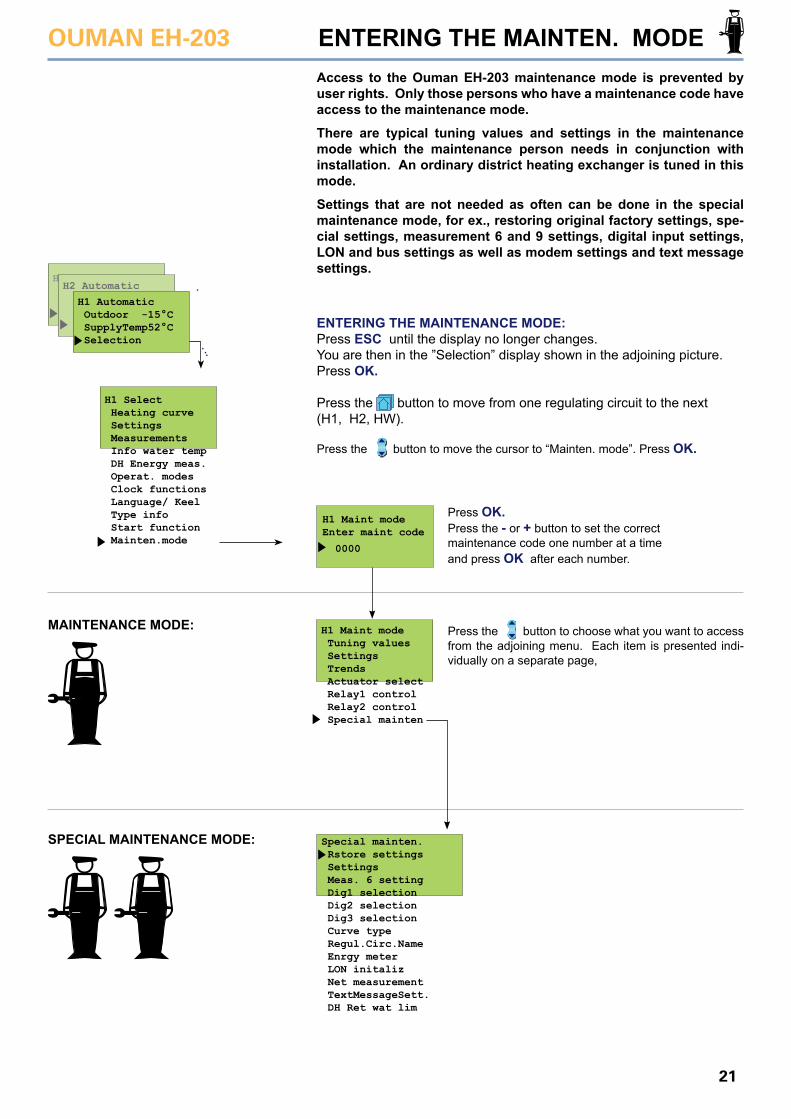
ENTERING THE MAINTEN. MODEAccess to the Ouman EH-203 maintenance mode is prevented by user rights. Only those persons who have a maintenance code have access to the maintenance mode.
There are typical tuning values and settings in the maintenance mode which the maintenance person needs in conjunction with installation. An ordinary district heating exchanger is tuned in this mode.
Settings that are not needed as often can be done in the special maintenance mode, for ex., restoring original factory settings, spe-cial settings, measurement 6 and 9 settings, digital input settings, LON and bus settings as well as modem settings and text message settings.
ENTERING THE MAINTENANCE MODE:Press ESC until the display no longer changes.You are then in the ”Selection” display shown in the adjoining picture. Press OK.
Press the button to move from one regulating circuit to the next(H1, H2, HW).
H1 Maint modeEnter maint code
0000
H1 Maint mode Tuning values Settings Trends Actuator select Relay1 control Relay2 control Special mainten
Special mainten. Rstore settings Settings Meas. 6 setting Dig1 selection Dig2 selection Dig3 selection Curve type Regul.Circ.Name Enrgy meter LON initaliz Net measurement TextMessageSett. DH Ret wat lim
Press the button to move the cursor to “Mainten. mode”. Press OK.
MAINTENANCE MODE:
SPECIAL MAINTENANCE MODE:
Press the button to choose what you want to access from the adjoining menu. Each item is presented indi-vidually on a separate page,
Press OK.Press the - or + button to set the correct maintenance code one number at a time and press OK after each number.
H1 Select Heating curve Settings Measurements Info water temp DH Energy meas. Operat. modes Clock functions Language/ Keel Type info Start function Mainten.mode
HWH2 Automatic
H1 Automatic Outdoor -15°C SupplyTemp52°C Selection
OUMAN EH-203
22
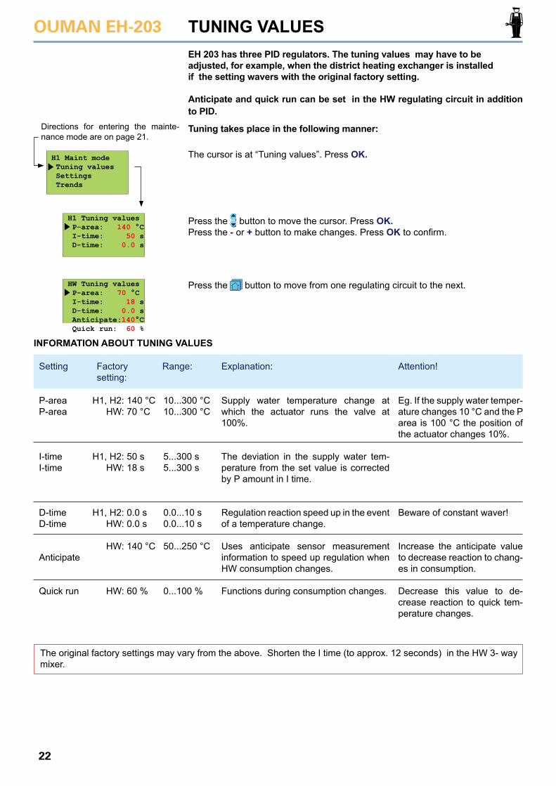
EH 203 has three PID regulators. The tuning values may have to be adjusted, for example, when the district heating exchanger is installedif the setting wavers with the original factory setting. Anticipate and quick run can be set in the HW regulating circuit in addition to PID.
Tuning takes place in the following manner:
TUNING VALUES
Directions for entering the mainte-nance mode are on page 21.
H1 Maint mode Tuning values Settings Trends
H1 Tuning values P-area: 140 °C I-time: 50 s D-time: 0.0 s
HW Tuning values P-area: 70 °C I-time: 18 s D-time: 0.0 s Anticipate:140°C Quick run: 60 %
The cursor is at “Tuning values”. Press OK.
Press the button to move the cursor. Press OK.Press the - or + button to make changes. Press OK to confirm.
Press the button to move from one regulating circuit to the next.
INFORMATION ABOUT TUNING VALUES
Supply water temperature change at which the actuator runs the valve at 100%.
The deviation in the supply water tem-perature from the set value is corrected by P amount in I time.
Regulation reaction speed up in the event of a temperature change.
Uses anticipate sensor measurement information to speed up regulation when HW consumption changes.
Functions during consumption changes.
Eg. If the supply water temper-ature changes 10 °C and the P area is 100 °C the position of the actuator changes 10%.
Beware of constant waver!
Increase the anticipate value to decrease reaction to chang-es in consumption.
Decrease this value to de-crease reaction to quick tem-perature changes.
P-areaP-area
I-time I-time
D-timeD-time
Anticipate
Quick run
H1, H2: HW:
H1, H2: HW:
H1, H2: HW:
HW:
HW:
140 °C70 °C
50 s18 s
0.0 s0.0 s
140 °C
60 %
10...300 °C10...300 °C
5...300 s5...300 s
0.0...10 s0.0...10 s
50...250 °C
0...100 %
The original factory settings may vary from the above. Shorten the I time (to approx. 12 seconds) in the HW 3- way mixer.
Setting Factory setting:
Attention!Explanation:Range:
OUMAN EH-203
23
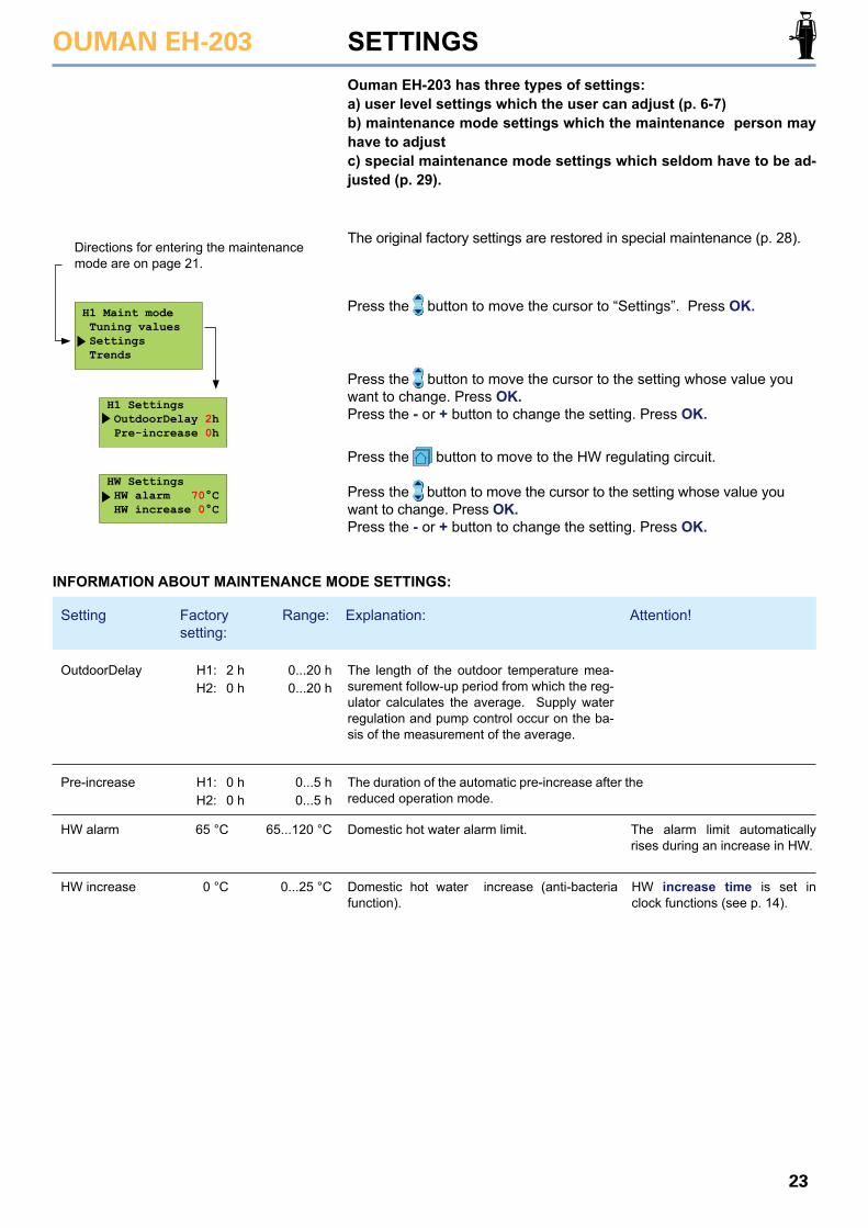
Ouman EH-203 has three types of settings:a) user level settings which the user can adjust (p. 6-7)b) maintenance mode settings which the maintenance person may have to adjustc) special maintenance mode settings which seldom have to be ad-justed (p. 29).
The original factory settings are restored in special maintenance (p. 28).
SETTINGS
HW Settings HW alarm 70°C HW increase 0°C
H1 Settings OutdoorDelay 2h Pre-increase 0h
Press the button to move the cursor to “Settings”. Press OK.
Directions for entering the maintenance mode are on page 21.
H1 Maint mode Tuning values Settings Trends
Press the button to move to the HW regulating circuit.
Press the button to move the cursor to the setting whose value you want to change. Press OK.Press the - or + button to change the setting. Press OK.
Press the button to move the cursor to the setting whose value you want to change. Press OK.Press the - or + button to change the setting. Press OK.
INFORMATION ABOUT MAINTENANCE MODE SETTINGS:
The length of the outdoor temperature mea-surement follow-up period from which the reg-ulator calculates the average. Supply water regulation and pump control occur on the ba-sis of the measurement of the average.
The duration of the automatic pre-increase after the reduced operation mode.
Domestic hot water alarm limit.
Domestic hot water increase (anti-bacteria function).
The alarm limit automatically rises during an increase in HW.
HW increase time is set in clock functions (see p. 14).
OutdoorDelay H1: 2 h0 h
0...20 h0...20 hH2:
H1:
65 °C
0 °C
0 h0 h
0...5 h
65...120 °C
0...25 °C
0...5 hH2:Pre-increase
HW alarm
HW increase
Setting Factory setting:
Attention!Explanation:Range:
OUMAN EH-203
24
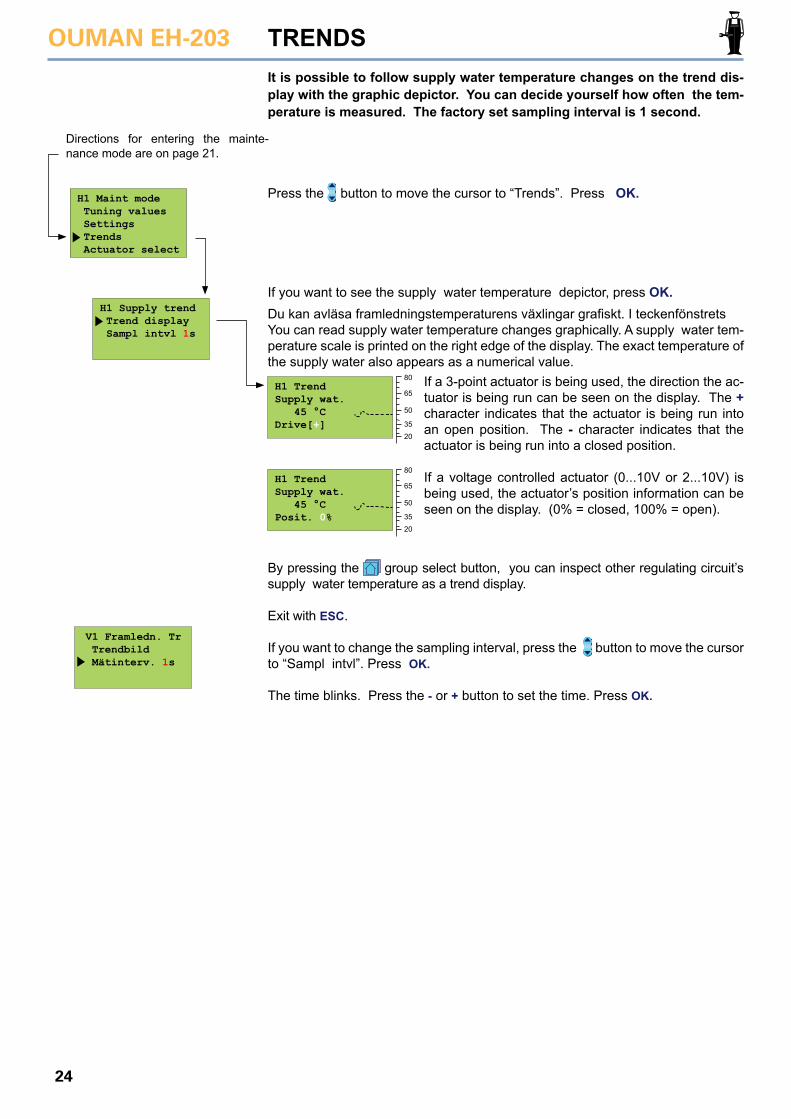
By pressing the group select button, you can inspect other regulating circuit’s supply water temperature as a trend display.
Exit with ESC.
If you want to change the sampling interval, press the button to move the cursor to “Sampl intvl”. Press OK.
The time blinks. Press the - or + button to set the time. Press OK.
H1 Maint mode Tuning values Settings Trends Actuator select
H1 Supply trend Trend display Sampl intvl 1s
H1 TrendSupply wat. 45 °CDrive[+]
H1 TrendSupply wat. 45 °CPosit. 0%
V1 Framledn. Tr Trendbild Mätinterv. 1s
It is possible to follow supply water temperature changes on the trend dis-play with the graphic depictor. You can decide yourself how often the tem-perature is measured. The factory set sampling interval is 1 second.
Press the button to move the cursor to “Trends”. Press OK.
TRENDS
Directions for entering the mainte-nance mode are on page 21.
If you want to see the supply water temperature depictor, press OK.Du kan avläsa framledningstemperaturens växlingar grafiskt. I teckenfönstrets You can read supply water temperature changes graphically. A supply water tem-perature scale is printed on the right edge of the display. The exact temperature of the supply water also appears as a numerical value.
If a 3-point actuator is being used, the direction the ac-tuator is being run can be seen on the display. The + character indicates that the actuator is being run into an open position. The - character indicates that the actuator is being run into a closed position.
If a voltage controlled actuator (0...10V or 2...10V) is being used, the actuator’s position information can be seen on the display. (0% = closed, 100% = open).
80
65
50
3520
80
65
50
3520
OUMAN EH-203
25
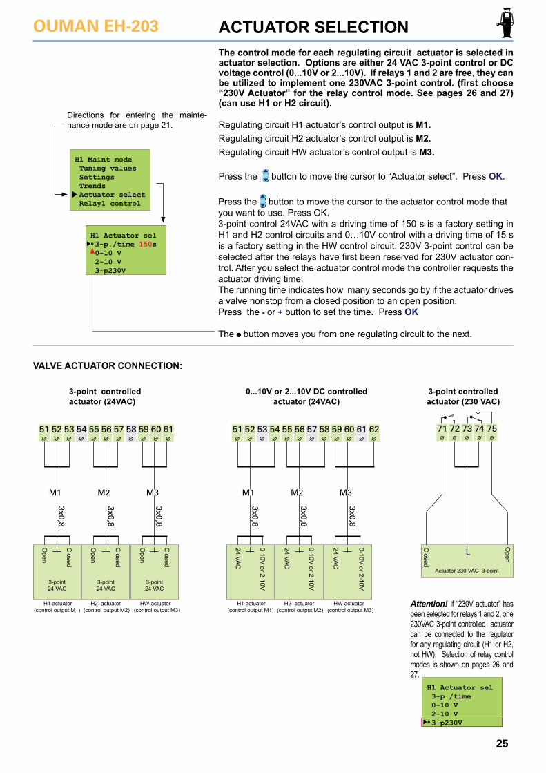
Press the button to move the cursor to the actuator control mode that you want to use. Press OK. 3-point control 24VAC with a driving time of 150 s is a factory setting in H1 and H2 control circuits and 0…10V control with a driving time of 15 s is a factory setting in the HW control circuit. 230V 3-point control can be selected after the relays have first been reserved for 230V actuator con-trol. After you select the actuator control mode the controller requests the actuator driving time. The running time indicates how many seconds go by if the actuator drives a valve nonstop from a closed position to an open position. Press the - or + button to set the time. Press OK
The button moves you from one regulating circuit to the next.
54 55 56 57 58 59 60 6151 52 53
3x0,8
3x0,8
3x0,8
M1 M2 M3
H1 Maint mode Tuning values Settings Trends Actuator select Relay1 control
The control mode for each regulating circuit actuator is selected in actuator selection. Options are either 24 VAC 3-point control or DC voltage control (0...10V or 2...10V). If relays 1 and 2 are free, they can be utilized to implement one 230VAC 3-point control. (first choose “230V Actuator” for the relay control mode. See pages 26 and 27) (can use H1 or H2 circuit).
Press the button to move the cursor to “Actuator select”. Press OK.
3-point controlled actuator (24VAC)
Attention! If “230V actuator” has been selected for relays 1 and 2, one 230VAC 3-point controlled actuator can be connected to the regulator for any regulating circuit (H1 or H2, not HW). Selection of relay control modes is shown on pages 26 and 27.
ACTUATOR SELECTION
Directions for entering the mainte-nance mode are on page 21.
H1 Actuator sel 3-p./time 150s 0-10 V 2-10 V 3-p230V
VALVE ACTUATOR CONNECTION:
Open
Open
Open
Closed
Closed
Closed
3-point 24 VAC
3-point24 VAC
3-point24 VAC
71 72 73 74 75
L
3-point controlled actuator (230 VAC)
Closed
Open
Actuator 230 VAC 3-point
HW actuator (control output M3)
HW actuator (control output M3)
H2 actuator (control output M2)
H2 actuator (control output M2)
H1 actuator(control output M1)
H1 actuator(control output M1)
3x0,8
3x0,8
3x0,8
54 55 56 57 58 59 60 61 6251 52 53
M1 M2 M3
0...10V or 2...10V DC controlled actuator (24VAC)
24 VAC
24 VAC
24 VAC
0-10V or 2-10V
0-10V or 2-10V
0-10V or 2-10V
Regulating circuit H1 actuator’s control output is M1.Regulating circuit H2 actuator’s control output is M2.Regulating circuit HW actuator’s control output is M3.
H1 Actuator sel 3-p./time 0-10 V 2-10 V 3-p230V
OUMAN EH-203
26
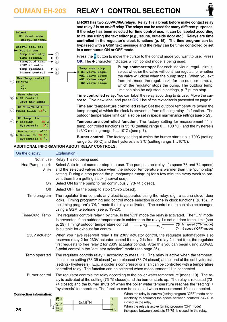
EH-203 has two 230VAC/6A relays. Relay 1 is a break before make contact relay and relay 2 is an on/off relay. The relays can be used for many different purposes. If the relay has been selected for time control use, it can be labeled according to its use using the text editor (e.g., sauna, out-side door etc.). Relays are time controlled in the regulator’s clock functions (p. 15). The time program can be bypassed with a GSM text message and the relay can be timer controlled or set in a continuous ON or OFF mode.
Relay1 ctrl sel Not in use Pump sumr stop Time program Time/Outd.temp 230V actuator Temp operated Burner control
HeatPump contrl Auto On Off
Name change R1 Control Give new label
R1 Time/Outd.t. Outd.t.lim -15°C
R1 Temp. lim. Setting 55°C Hysteresis 3°C
Burner control°C Burner ON 70 °C Hysteresis 5 °C
RELAY 1 CONTROL SELECTION
Pump sumr stop H1 Valve regul H1 Valve close H2 Valve regul H2 Valve close
Pump sommarstopp: For each individual regul. circuit, select whether the valve will continue regulat. or whether the valve will close when the pump stops. When you exit from this mode the regul. asks for the outdoor temp. at which the regulator stops the pump. The outdoor temp. limit can also be adjusted in settings, p. 7 pump stop.
Time controlled relay: You can label the relay according to its use. Move the cur-sor to: Give new label and press OK. Use of the text editor is presented on page 8.Time and temperature controlled relay: Set the outdoor temperature (when the temp. drops) at which the clock is prevented from effecting relay 1’s function. The outdoor temperature limit can also be set in special maintenance settings (see p. 29).Temperature controlled function: The factory setting for measurement 11 in temp. controlled functions is 55 °C (setting range 0 ... 100 °C) and the hysteresis is 3°C (setting range 1 ... 10°C).(see p.7).Burner control: The factory setting at which the burner starts up is 70°C (setting range 5…95°C) and the hysteresis is 3°C (setting range 1…10°C).
1
1
2
2
4
4
3
3
5
5
ADDITIONAL INFORMATION ABOUT RELAY CONTROLS:
Relay 1 is not being used.Select Auto to put summer stop into use. The pumps stop (relay 1’s space 73 and 74 opens) and the selected valves close when the outdoor temperature is warmer than the “pump stop” setting. During a stop period the pump/pumps runs(run) for a few minutes every week to pre-vent them from getting stuck (interval use).Select ON for the pump to run continuously (73-74 closed).Select OFF for the pump to stop (73-75 closed). The regulator time controls any electric apparatus using the relay, e.g., a sauna stove, door locks. Timing programming and control mode selection is done in clock functions (p. 15). In the timing program’s “ON” mode the relay is activated. The control mode can also be changed using a GSM telephone (see p. 19-20).
When you have reserved relay 1 for 230V actuator control, the regulator automatically also reserves relay 2 for 230V actuator control if relay 2 is free. If relay 2 is not free, the regulator first requests to free relay 2 for 230V actuator control. After this you can begin using 230VAC 3-point control in the “actuator selection” mode (see page 25). The regulator controls relay 1 according to meas. 11. The relay is active when the temperat. rises to the setting (73-35 closed ) and released (73-74 closed) at the end of the set hysteresis (setting - hysteresis). E.g., a cooler’s compressor or a fan can be controlled with a temperature controlled relay. The function can be selected when measurement 11 is connected. The regulator controls the relay according to the boiler water temperature (meas. 10). The re-lay is activated at the setting (73-75 closed) and the burner starts up. The relay is released (73-74 closed) and the burner shuts off when the boiler water temperature reaches the “setting” + “hysteresis” temperature. The function can be selected when measurement 10 is connected.
When the relay is inactive (timing program “OFF” mode or no electricity to actuator) the space between contacts 73-74 is closed in the relay.When the relay is active (timing program “ON” mode) the space between contacts 73-75 is closed in the relay.
On the display: Explanation:Not in use
HeatPump contrl:
OnOff
Time program
230V actuator
Temp operated
Burner control
Connection information:
The regulator controls relay 1 by time. In the “ON” mode the relay is activated. The “ON” mode is prevented if the outdoor temperature is colder than the relay 1’s set outdoor temp. limit (see p. 29). Timing/ outdoor temperature control is suitable for exhaust fan control.
Time/Outd. Temp
1/1 speed (“ON” mode)½ speed (“OFF”-mode)
7574
73
7475
3x1.5 N
L73
Select H1 Maint mode Relay1 control
Press the button to move the cursor to the control mode you want to use. Press OK. The character indicates which control mode is being used.
Auto
OUMAN EH-203
27
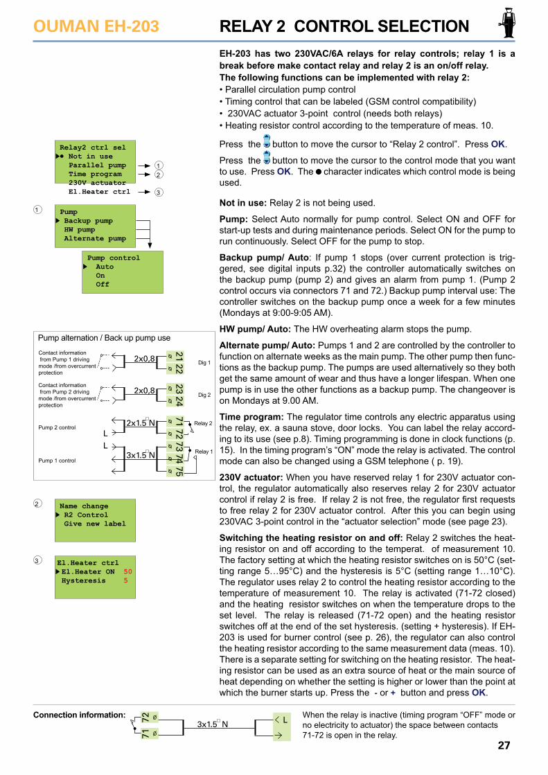
EH-203 has two 230VAC/6A relays for relay controls; relay 1 is a break before make contact relay and relay 2 is an on/off relay.The following functions can be implemented with relay 2:• Parallel circulation pump control• Timing control that can be labeled (GSM control compatibility)• 230VAC actuator 3-point control (needs both relays)• Heating resistor control according to the temperature of meas. 10.
RELAY 2 CONTROL SELECTION
Not in use: Relay 2 is not being used.
Pump: Select Auto normally for pump control. Select ON and OFF for start-up tests and during maintenance periods. Select ON for the pump to run continuously. Select OFF for the pump to stop.
Backup pump/ Auto: If pump 1 stops (over current protection is trig-gered, see digital inputs p.32) the controller automatically switches on the backup pump (pump 2) and gives an alarm from pump 1. (Pump 2 control occurs via connectors 71 and 72.) Backup pump interval use: The controller switches on the backup pump once a week for a few minutes (Mondays at 9:00-9:05 AM).
HW pump/ Auto: The HW overheating alarm stops the pump.
Alternate pump/ Auto: Pumps 1 and 2 are controlled by the controller to function on alternate weeks as the main pump. The other pump then func-tions as the backup pump. The pumps are used alternatively so they both get the same amount of wear and thus have a longer lifespan. When one pump is in use the other functions as a backup pump. The changeover is on Mondays at 9.00 AM.
Time program: The regulator time controls any electric apparatus using the relay, ex. a sauna stove, door locks. You can label the relay accord-ing to its use (see p.8). Timing programming is done in clock functions (p. 15). In the timing program’s “ON” mode the relay is activated. The control mode can also be changed using a GSM telephone ( p. 19).
230V actuator: When you have reserved relay 1 for 230V actuator con-trol, the regulator automatically also reserves relay 2 for 230V actuator control if relay 2 is free. If relay 2 is not free, the regulator first requests to free relay 2 for 230V actuator control. After this you can begin using 230VAC 3-point control in the “actuator selection” mode (see page 23).
Switching the heating resistor on and off: Relay 2 switches the heat-ing resistor on and off according to the temperat. of measurement 10. The factory setting at which the heating resistor switches on is 50°C (set-ting range 5…95°C) and the hysteresis is 5°C (setting range 1…10°C).The regulator uses relay 2 to control the heating resistor according to the temperature of measurement 10. The relay is activated (71-72 closed) and the heating resistor switches on when the temperature drops to the set level. The relay is released (71-72 open) and the heating resistor switches off at the end of the set hysteresis. (setting + hysteresis). If EH-203 is used for burner control (see p. 26), the regulator can also control the heating resistor according to the same measurement data (meas. 10). There is a separate setting for switching on the heating resistor. The heat-ing resistor can be used as an extra source of heat or the main source of heat depending on whether the setting is higher or lower than the point at which the burner starts up. Press the - or + button and press OK.
Relay2 ctrl sel Not in use Parallel pump Time program 230V actuator El.Heater ctrl
12
3
Name change R2 Control Give new label
2
El.Heater ctrl El.Heater ON 50 Hysteresis 5
3
When the relay is inactive (timing program “OFF” mode or no electricity to actuator) the space between contacts 71-72 is open in the relay.
Connection information:
Pump Backup pump HW pump Alternate pump
1
Pump control Auto On Off
2122
2324
2x0,8
2x0,8
7172
7374
75
2x1.5 NL
3x1.5 NL
Pump 2 control
Pump 1 control
Pump alternation / Back up pump use
Contact information from Pump 1 driving mode /from overcurrentprotection
Contact information from Pump 2 driving mode /from overcurrentprotection
Relay 1
Relay 2
Dig 1
Dig 2
72 3x1.5 N L
71Press the button to move the cursor to “Relay 2 control”. Press OK.
Press the button to move the cursor to the control mode that you want to use. Press OK. The character indicates which control mode is being used.
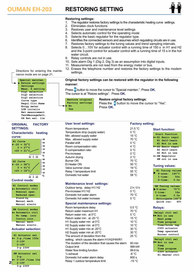
OUMAN EH-203
28
Restore original factory settings: Press the button to move the cursor to ”Yes”.Press OK.
Restoring settings:1. The regulator restores factory settings to the charasteristic heating curve settings.2. Eliminates clock functions3. Restores user and maintenance level settings4. Selects automatic control for the operating mode5. Selects the basic regulator for the regulator type. 6. Identifies the connected sensors and assumes which regulating circuits are in use.7. Restores factory settings to the tuning values and trend sampling intervals.8. Selects 0…10V for actuator control with a running time of 150 s in H1 and H2
and the 3-point control for actuator control with a running time of 15 s in the hot water circuit.
9. Relay controls are not in use.10. Sets alarm Dig 1 (Dig 2, Dig 3) as an assumption into digital inputs.11. Measurements are not read from the energy meter or bus. 12. Erases the telephone number and restores the factory settings to the modem
settings.
Press button to move the cursor to ”Special mainten.”. Press OK. The cursor is at ”Rstore settings”. Press OK.
Room temperatureTemperature drop (supply water) Min. allowed supply water Max. allowed supply waterParallel shiftRoom compensation ratio E-compensation ratio Pre-increase Autumn dryingBurner ONEl.Heater ON Valve summer close Relay 1 temperature limit Domestic hot water
21.5 °C0 °C15 °C70 °C0 °C4 °C0 °C0 °C2 °C70 °C50 °C19 °C55 °C58 °C
0.5 °C70 °C5 °C15 °C10 °C10 °C30 °C30 °C25 °C
60 min999 kW99.9 l/s-6 °C600 s -15 °C
2 h / 0 h0 °C70 °C0 °C
Outdoor temp. delay H1/ H2Pre-increase H1/ H2Domestic hot water alarm Domestic hot water increase
Room temperature delayReturn water maximum H1Return water min. at 0°CReturn water min at -20 °CH1 Supply water min at 0°CH2 Supply water min at 0°CH1 Supply water min at -20°CH2 Supply water min at -20°C The amount of deviation from thesetting, which causes the alarm H1/H2/HW/R1The duration of the deviation that causes the alarmOutput limitWater flow limiting function½ exhaustDomestic hot water alarm delayRelay 1 outdoor temperature limit
RESTORING SETTING
Restore originalFactory settings No Yes
Special mainten. Rstore settings Settings Meas. 6 setting Dig1 selection Dig2 selection Dig3 selection Curve type Regul.Circ.Name Enrgy meter LON initaliz Net measurement TextMessageSett. DH Ret.wat. lim
Directions for entering the mainte-nance mode are on page 21.
ORIGINAL FACTORY SETTINGS:
User level settings:
Maintenance level settings:
Special maintenance settings:
Factory setting:
Characteristic heating curve:
H2 Curve -20 = 58°C 0 = 41°C +20 = 18°C
°C20
20
35506580
0 -20
H1 Curve -20 = 32°C 0 = 27°C +20 = 21°C
°C20
20
35506580
0 -20
Control mode:
H1 Actuator sel 3-p./time 150s 0-10V 2-10V 3-p 230V
HW Actuator sel 3-p. 0-10V./time 15s 2-10V 3-p 230V
Actuator selection:
Start function:
Tuning values:
Relays:
H1 Control modes Automatic ctrl Nominal oper. Reduced oper. Stand-by Manual mech. Manual electr
HW Control modes Automatic ctrl No temp. incr Contin.incr. Manual mech. Manual electr.
Start function H1 Basic regul H1 Self-learn H1 Not in use H2 Basic regul H2 Self-learn H2 Not in use HW Regulator HW not in use
H1 Tuning values P-area: 140°C I-time: 50s D-time: 0.0s
HW Tuning values P-area: 70°CI-time: 18s D-time: 0.0s Anticipate:140°C Quick run: 60%
Relay1 ctrl sel Not in use Heat.pump Time program Time/Outdr tmp 230V actuator Temp operated Burner control
Relay2 ctrl sel Not in use Pump Time program 230V actuator El.Heater ctrl
Original factory settings can be restored with the regulator in the followingmanner:
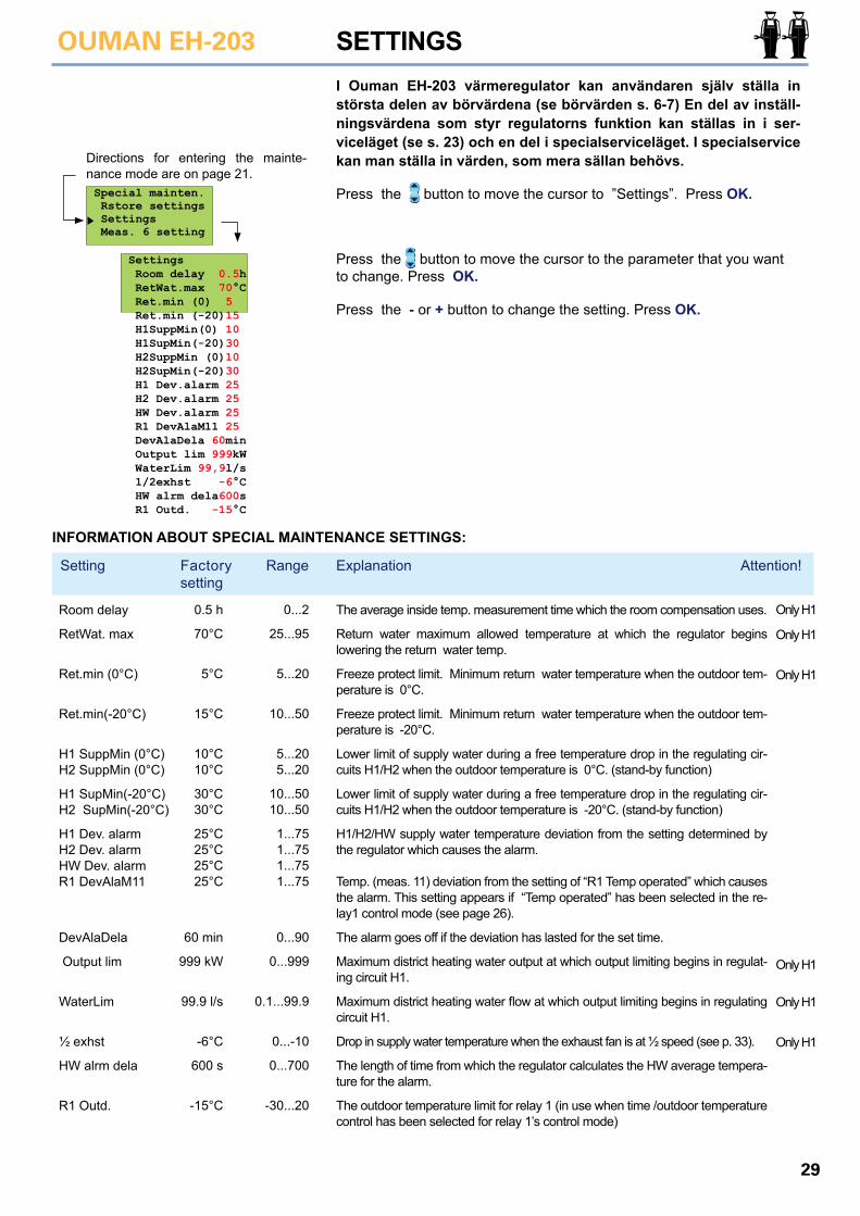
29
OUMAN EH-203 SETTINGS
INFORMATION ABOUT SPECIAL MAINTENANCE SETTINGS:
Setting Factory setting
Explanation Attention!Range
Room delay
RetWat. max
Ret.min (0°C)
Ret.min(-20°C)
H1 SuppMin (0°C)H2 SuppMin (0°C)
H1 SupMin(-20°C)H2 SupMin(-20°C)
H1 Dev. alarmH2 Dev. alarmHW Dev. alarmR1 DevAlaM11
DevAlaDela
Output lim
WaterLim
½ exhst
HW alrm dela
R1 Outd.
The average inside temp. measurement time which the room compensation uses.
Return water maximum allowed temperature at which the regulator begins lowering the return water temp.
Freeze protect limit. Minimum return water temperature when the outdoor tem-perature is 0°C.
Freeze protect limit. Minimum return water temperature when the outdoor tem-perature is -20°C.
Lower limit of supply water during a free temperature drop in the regulating cir-cuits H1/H2 when the outdoor temperature is 0°C. (stand-by function)
Lower limit of supply water during a free temperature drop in the regulating cir-cuits H1/H2 when the outdoor temperature is -20°C. (stand-by function)
H1/H2/HW supply water temperature deviation from the setting determined by the regulator which causes the alarm.
Temp. (meas. 11) deviation from the setting of “R1 Temp operated” which causes the alarm. This setting appears if “Temp operated” has been selected in the re-lay1 control mode (see page 26).
The alarm goes off if the deviation has lasted for the set time.
Maximum district heating water output at which output limiting begins in regulat-ing circuit H1.
Maximum district heating water flow at which output limiting begins in regulating circuit H1.
Drop in supply water temperature when the exhaust fan is at ½ speed (see p. 33).
The length of time from which the regulator calculates the HW average tempera-ture for the alarm.
The outdoor temperature limit for relay 1 (in use when time /outdoor temperature control has been selected for relay 1’s control mode)
0.5 h
70°C
5°C
15°C
10°C10°C
30°C30°C
25°C25°C25°C25°C
60 min
999 kW
99.9 l/s
-6°C
600 s
-15°C
0...2
25...95
5...20
10...50
5...205...20
10...5010...50
1...751...751...751...75
0...90
0...999
0.1...99.9
0...-10
0...700
-30...20
Only H1
Only H1
Only H1
Only H1
Only H1
Only H1
I Ouman EH-203 värmeregulator kan användaren själv ställa in största delen av börvärdena (se börvärden s. 6-7) En del av inställ-ningsvärdena som styr regulatorns funktion kan ställas in i ser-viceläget (se s. 23) och en del i specialserviceläget. I specialservice kan man ställa in värden, som mera sällan behövs.Directions for entering the mainte-
nance mode are on page 21.Special mainten. Rstore settings Settings Meas. 6 setting
Settings Room delay 0.5h RetWat.max 70°C Ret.min (0) 5 Ret.min (-20)15 H1SuppMin(0) 10 H1SupMin(-20)30 H2SuppMin (0)10 H2SupMin(-20)30 H1 Dev.alarm 25 H2 Dev.alarm 25 HW Dev.alarm 25 R1 DevAlaM11 25 DevAlaDela 60min Output lim 999kW WaterLim 99,9l/s 1/2exhst -6°C HW alrm dela600s R1 Outd. -15°C
Press the button to move the cursor to the parameter that you want to change. Press OK.
Press the - or + button to change the setting. Press OK.
Press the button to move the cursor to ”Settings”. Press OK.
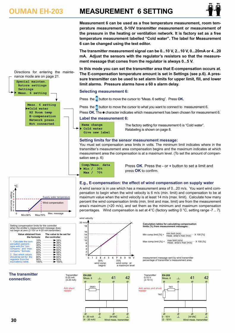
OUMAN EH-203
30
Press the button to move the cursor to “Meas. 6 setting”. Press OK.
Press the button to move the cursor to what you want to connect to measurement 6. Press OK. The character indicates which measurement has been chosen for measurement 6.
MEASUREMENT 6 SETTING
Directions for entering the mainte-nance mode are on page 21.Special mainten. Rstore settings Settings Meas. 6 setting
Measurement 6 can be used as a free temperature measurement, room tem-perature measurement, 0-10V transmitter measurement or measurement of the pressure in the heating or ventilation network. It is factory set as a free temperature measurement labelled “Cold water”. The label for Measurement 6 can be changed using the text editor.
The transmitter measurement signal can be 0...10 V, 2...10 V, 0...20mA or 4...20 mA. Adjust the sensors with the regulator’s resistors so that the measure-ment message that comes from the regulator is always 0...5 V.
In this mode you can set the transmitter area that E-compensation occurs at. The E-compensation temperature amount is set in Settings (see p.6). A pres-sure transmitter can be used to set alarm limits for upper limit, fill, and lower limit alarms. Pressure alarms have a 60 s alarm delay.
Meas. 6 setting Cold water H2 Room temp E-compensation Network press. Not connected Name change
Cold water Give new label
Selecting measurement 6:
The transmitter connection:
The factory setting for measurement 6 is “Cold water”. Relabeling is shown on page 8.
Press OK. Press the - or + button to set a limit andpress OK to confirm.
Setting limits for the sensor measurement message: You must set compensation area limits in volts. The minimum limit indicates where in the transmitter’s measurement area compensation begins and the maximum indicates at which measurement area the compensation is at a maximum level. (To set the amount of compen-sation see p. 6)
E.g., E-compensation: the effect of wind compensation on supply waterA wind sensor is in use which has a measurement area of 0...20 m/s. You want wind com-pensation to begin when the wind velocity is 6 m/s (min. limit) and compensation to be at maximum value when the wind velocity is at least 14 m/s (max. limit). Calculate how many percent the wind compensation limits (min. limit and max. limit) are from the measurement area’s maximum (=20 m/s), and set them as the minimum and maximum compensation percentages. Wind compensation is set at 4°C (factory setting 0 °C, setting range -7 ... 7).
Comp/Meas. data Min / 30% Max / 70%
°C
76543210
0Min/30% Max/70%
Mes. message
win
d co
mp.
set
ting
Supply water temperature
Wind compensation
Setting compensation limits for the controllerwhen the emitter’s measurement message does not begin at zero (2-10V or 4-20 mA transmitter)
Value obtained from the formula:
1. Calculate the com-pensation percent-ages with the “min. compens.” and “max. compens.” formula.2. See which values should be set for the regulator from the equivalency table.
The value to be set for the controller
10% 28%20% 36%30% 44%40% 52%50% 60%60% 68%70% 76%80% 84%90% 92%100% 100%
20 m/s
1416
18
121086420
0 1 2 3 4 5 6 7 8 9 10 V
wind velocity
30% wind comp. begins
70%wind comp. at a maximum level
measurement message sent by wind transmitterpercentage of transmitter’s measurement area
Calculation tables for calculating compensation limits (%) from measurement messages:
Min comp.limit [%] = X 100 [%]min limit (m/s)meas. area’s max (m/s)
Max comp.limit [%] = X 100 [%]max limit (m/s)meas. area’s max (m/s)
4241EH-203Meas. 6
24 VAC
250Ω
0 - 20 mA(4 - 20 mA)
Transmitter0-20 mA(4-20 mA)
Add shuntresistor
Wind meas. transmitter
4241EH-203Meas. 6
24 VAC
1kΩ
1kΩ
0 - 10 V(2 - 10 V)
Transmitter0-10 V(2-10 V)
Add series and shunt resistor
Wind meas. transmitter
Label the measurement 6:
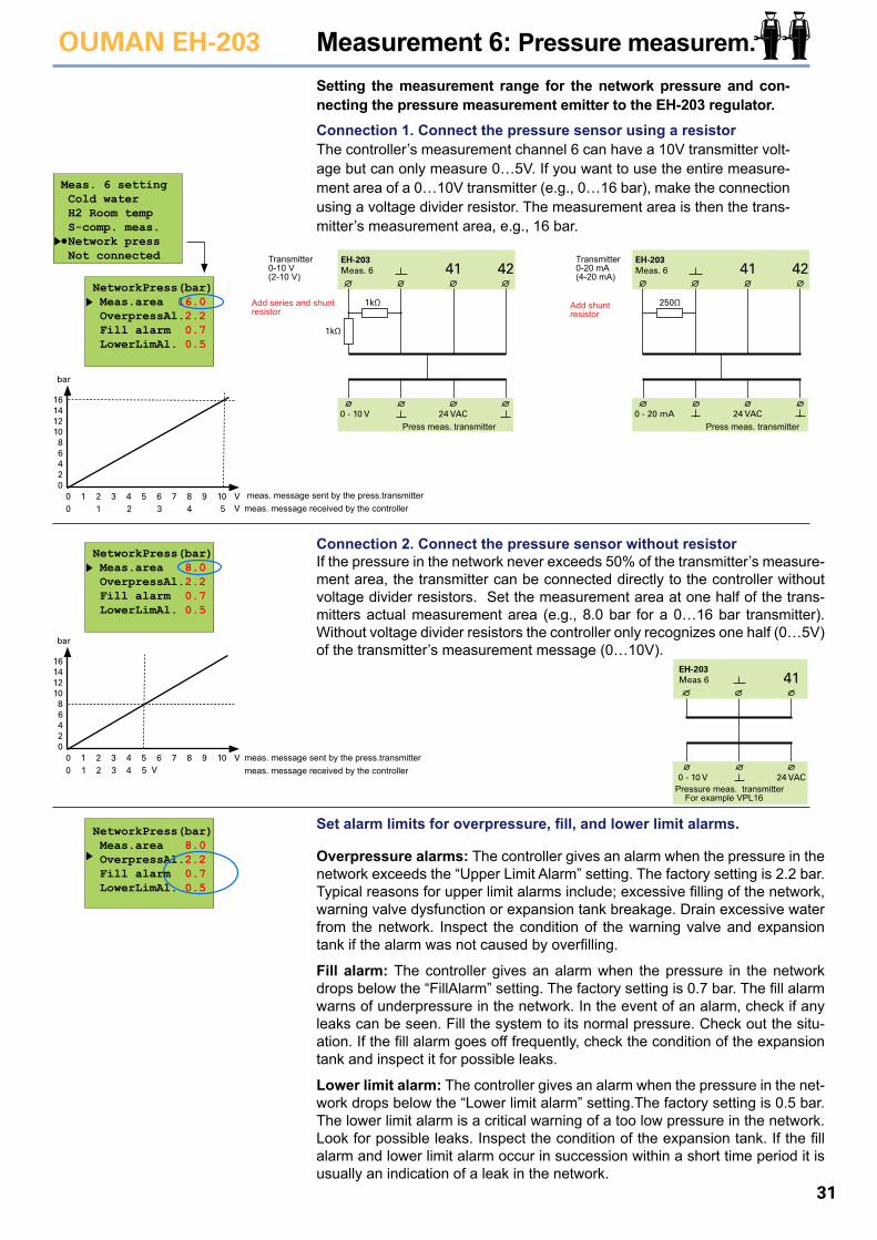
31
OUMAN EH-203 Measurement 6: Pressure measurem.Setting the measurement range for the network pressure and con-necting the pressure measurement emitter to the EH-203 regulator.
Meas. 6 setting Cold water H2 Room temp S-comp. meas. Network press Not connected
NetworkPress(bar) Meas.area 16.0 OverpressAl.2.2 Fill alarm 0.7 LowerLimAl. 0.5
Connection 2. Connect the pressure sensor without resistorIf the pressure in the network never exceeds 50% of the transmitter’s measure-ment area, the transmitter can be connected directly to the controller without voltage divider resistors. Set the measurement area at one half of the trans-mitters actual measurement area (e.g., 8.0 bar for a 0…16 bar transmitter). Without voltage divider resistors the controller only recognizes one half (0…5V) of the transmitter’s measurement message (0…10V).
Set alarm limits for overpressure, fill, and lower limit alarms.
Overpressure alarms: The controller gives an alarm when the pressure in the network exceeds the “Upper Limit Alarm” setting. The factory setting is 2.2 bar. Typical reasons for upper limit alarms include; excessive filling of the network, warning valve dysfunction or expansion tank breakage. Drain excessive water from the network. Inspect the condition of the warning valve and expansion tank if the alarm was not caused by overfilling.
Fill alarm: The controller gives an alarm when the pressure in the network drops below the “FillAlarm” setting. The factory setting is 0.7 bar. The fill alarm warns of underpressure in the network. In the event of an alarm, check if any leaks can be seen. Fill the system to its normal pressure. Check out the situ-ation. If the fill alarm goes off frequently, check the condition of the expansion tank and inspect it for possible leaks.
Lower limit alarm: The controller gives an alarm when the pressure in the net-work drops below the “Lower limit alarm” setting.The factory setting is 0.5 bar. The lower limit alarm is a critical warning of a too low pressure in the network. Look for possible leaks. Inspect the condition of the expansion tank. If the fill alarm and lower limit alarm occur in succession within a short time period it is usually an indication of a leak in the network.
bar
1416
121086420
00
112
23
34
45
56 7 8 9 10 V
V meas. message sent by the press.transmittermeas. message received by the controller
bar
1416
121086420
00
11
22
33
44
55
6 7 8 9 10 VV
meas. message sent by the press.transmittermeas. message received by the controller
NetworkPress(bar) Meas.area 8.0 OverpressAl.2.2 Fill alarm 0.7 LowerLimAl. 0.5
NetworkPress(bar) Meas.area 8.0 OverpressAl.2.2 Fill alarm 0.7 LowerLimAl. 0.5
Add shunt resistor
4241EH-203Meas. 6
24 VAC
250Ω
0 - 20 mA
Transmitter0-20 mA(4-20 mA)
Press meas. transmitter
4241EH-203Meas. 6
24 VAC
1kΩ
1kΩ
0 - 10 V
Transmitter0-10 V(2-10 V)
Add series and shuntresistor
Press meas. transmitter
41EH-203Meas 6
24 VAC0 - 10 VPressure meas. transmitter For example VPL16
Connection 1. Connect the pressure sensor using a resistorThe controller’s measurement channel 6 can have a 10V transmitter volt-age but can only measure 0…5V. If you want to use the entire measure-ment area of a 0…10V transmitter (e.g., 0…16 bar), make the connection using a voltage divider resistor. The measurement area is then the trans-mitter’s measurement area, e.g., 16 bar.
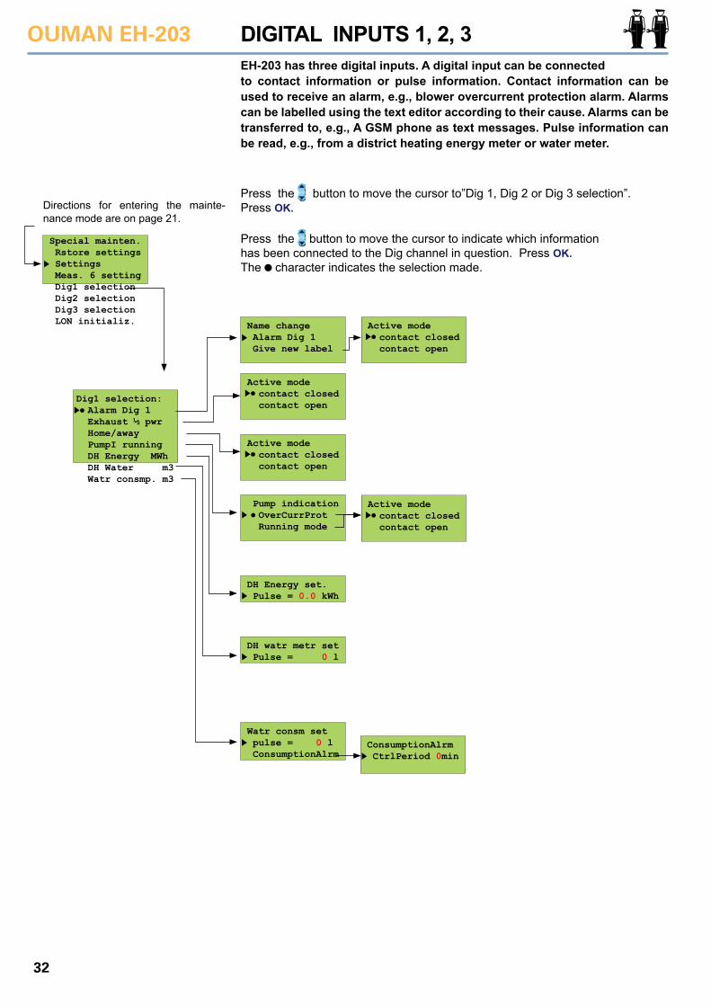
OUMAN EH-203
32
Press the button to move the cursor to indicate which informationhas been connected to the Dig channel in question. Press OK. The character indicates the selection made.
DIGITAL INPUTS 1, 2, 3
Directions for entering the mainte-nance mode are on page 21.
Special mainten. Rstore settings Settings Meas. 6 setting Dig1 selection Dig2 selection Dig3 selection LON initializ.
EH-203 has three digital inputs. A digital input can be connectedto contact information or pulse information. Contact information can be used to receive an alarm, e.g., blower overcurrent protection alarm. Alarms can be labelled using the text editor according to their cause. Alarms can be transferred to, e.g., A GSM phone as text messages. Pulse information can be read, e.g., from a district heating energy meter or water meter.
Dig1 selection: Alarm Dig 1 Exhaust ½ pwr Home/away PumpI running DH Energy MWh DH Water m3 Watr consmp. m3
Name change Alarm Dig 1 Give new label
Active mode contact closed contact open
Active mode contact closed contact open
Active mode contact closed contact open
Active mode contact closed contact open
Pump indication OverCurrProt Running mode
DH Energy set. Pulse = 0.0 kWh
DH watr metr set Pulse = 0 l
Watr consm set pulse = 0 l ConsumptionAlrm
ConsumptionAlrm CtrlPeriod 0min
Press the button to move the cursor to”Dig 1, Dig 2 or Dig 3 selection”. Press OK.
33
OUMAN EH-203
ConsumptionAlrm CtrlPeriod 0min
Alarm switch information. When the switch is closed, an alarm goes off. You can use the text editor to label the alarm, e.g., Thermal relayl! (see p. 8). In the event of an alarm, the regulator sounds the alarm and indicates on the display from which digital input the alarm came from. Transferring the alarm to a GSM phone (see p. 39, 40. After pressing ESC, the controller asks the active mode of the contact, in other words, when the controller gives an alarm. If a closing contact is in use, select “Switch closed” as the active mode. If an opening contact is in use, select “switch open” as the active mode.
Pulse information from the district heating energy meter: Press OK. Set the number of kWh equivalent to one pulse and press OK. District heating energy consumption (MWh) and the momentary (5 min. follow-up period) district heating power consumption (kW) can be seen on the regulator’s measurements display.
The purpose of this function is check that the pump is in operating condition. Select whet-her to inspect pump running from running mode information or from information received from overflow protection. Overcurrent protection: In speed controlled pumps, pump indication is taken from alarm contacts or from a separate overcurrent protection in the input current circuit. You can select how you want the switch to work. As a factory setting the switch closes when an alarm is given (=in the active mode the switch is closed) . If the alarm is given when the alarm contact closes, the alarm is acknowledged from a separate switch. The alarm may stop sounding after a power failure. Contact information for constant speed pumps is taken from the pump’s temperature relay. When the contact is closed the pump does not run. The controller then gives an alarm and starts up the other pump (if the alternate pump is in use).Running mode: Pump running mode information is taken from a separate potential free closing contact in the input current circuit. (The pump runs when the contact is closed). Speed controlled pumps usually do not have their own running information contact. If a speed controlled pump is controlled by cutting the supply voltage (not recommended) the
pump’s own alarm contact can be connected as an opening contact to the input current circuit as a series with the potential free contact. (see diagram to the right). Compare the running information and control. If control and running information are not in the same mode the controller gives a contradiction alarm if the contra-dicting situation has lasted for 10s. In a contradicting situation the controller keeps controlling the pump. When the contradiction ends the alarm is turned off.
Pulse information from the district heating water meter: Press OK. Set the number of liters equivalent to one pulse and press OK. District heating water consumption (DH m3) and the momentary district heating water consumption (Inst. l/s) can be seen on the regula-tor’s measurements display.
Pulse information from the facility’s water meter: Press OK. Set the number of liters equivalent to one pulse and press OK. The facility’s water consumption (Water m3) can be seen on the regulator’s measurements display.
Exhaust fan ½ speed information. When the switch is closed the exhaust fan is at ½ speed. The information is used to lower the heat when the exhaust fan is at ½ speed. The amount of the drop is given in special maintenance settings (see p. 29, ½ exhst). The active mode means that the exhaust pump runs at ½ speed.
Away switch information. (switch closed, H1/H2 reduced temperature mode is on). The active mode means the away mode.
Exhaust ½pwr
Home/away
2122
Dig 1
Speed con-trolled pump’s own alarm contact
Closing runninginformation
Alarm use:
DH Energy set
DH watr metr set
Watr consm set
Pump 1(2) running:
Inspection of hot water network for leaks: Press OK. Set the length of the control period. Press OK. If in a 24 hour period there is no time period with no consumption for the length of the control period the controller gives a consumption alarm indicating continuous hot water consumption. With the setting at 0 (factory setting) the function is not in use. The setting range is 0…99 minutes. The alarm can also be auto-matically acknowledged if there is a pulseles control period during the next 24 hour period. This function can be used to discern moderate sized leaks, e.g., a leaking toilet.
In display: Explanation
34
OUMAN EH-203
Select a 3-point curve or 5-point curve and press OK.The character indicates the selection made. Set heating curves are displayed and can be adjusted in “Heating curve”, see p. 4.
HEATING CURVE TYPE SELECTION
Directions for entering the mainte-nance mode are on page 21. Special mainten. Rstore settings Settings Meas. 6 setting Dig1 selection Dig2 selection Dig3 selection Curve type Regul.Circ.Name
Selection of a three point or five point heating curve. A 3-point curve is a fac-tory setting.
Press the button to move the cursor to ”Curve type”. Press OK.
Curve type 3-point 5-point
5
4
2
20 0 -20 °C
3
1
Outdoor temperature
Supply water
3
20 0 -20 °C
2
1
Supply water
Outdoor temp.
You can adjust the heating curve with outdoor tem-perature values - 20°C and +20°C and with three additional outdoor temperatures between -20°C - +20°C. Note! The automatic proposed correction and self-learning are not in use!
You can adjust the heating curve with outdoor tem-perature values 20°C, 0°C and +20°C. EH-203 pre-vents you from making a heating curve of the wrong shape. It automatically proposes a correction. If a 3-point curve has been selected it is possible to take self-learning into use (see p. 17), and the controller will automatically adjust the heating curve according to feedback from the room sensor.
3-point curve:
5-point curve:
35
OUMAN EH-203 LABELLING CONTROL CIRCUITS
Directions for entering the mainte-nance mode are on page 21.Special mainten. Rstore settings Settings Meas. 6 setting Dig1 selection Dig2 selection Dig3 selection Curve type Regul.Circ.Name LON initializ.
Press the button to move the cursor to ”Regul.Circ.Name”. Press OK.
Regul.Circ.Name H1: H2:
H1 Automatic Outdoor-15°C SupplyTemp52°C Selection
H1 Radiator netw Outdoor-15°C SupplyTemp52°C Selection
Name change H1: Give new label
Name change H1: _
After labelling control circuits, the top row of the controller’s basic display will alternately display the control mode and name of the control circuit.
Move the cursor to the control circuit (H1,H2), that you want to label. Press OK.
Move the cursor to “Give new label”. Press OK. “-” blinks. Write the name using the text editor. You can move forward or backward in the character row with the - or + button. Confirm the number by pressing OK, then the same number that you se-lected will blink in the next space. Whichever has been selected last can be deleted by pressing ESC. If you press the ESC button for a while, the number will be deleted and the number that was previously fed will remain in effect. When you are ready, press OK for a while (over 2 secretary.).
Label the control circuit according to its target area. E.g., floor heating or preheating for air conditioning.
Hint!Hint!
OUMAN EH-203
36
ENERGY METERTake into use:
Press the button to move the cursor to “Energy meter””.
Press OK.
Taking automatic reporting into use:
Press the button to move cursor to “Connected”. Press OK.
A report is not sent when the set value is 0. Otherwise the report is sent on a set day. If there are fewer days in the month than the set reporting day, the report is sent on the last day of that month.
Write the GSM number that the controller sends the report to from the energy meter as a text message. The number is given with the text editor as follows:
Press the button to move the cursor to “Change”. Press OK. “O” blinks.
Write the telephone number using the text editor.
You can move forward or backward in the character row with the - or + button. Con-firm the number by pressing OK, then the same number that you selected will blink in the next space. Whichever has been selected last can be deleted by pressing ESC. If you press the ESC button for a while, the number will be deleted and the number that was previously fed will remain in effect. When you are ready, press OK for a while (over 2 secretary).
• Attach the magnetic surface of the EMR-200 to the energy meter so that the connecting cord goes down.
• The Kamstrup Multical energy meter has control knobs for positioning the EMR-200. Install the EMR-200 energy meter so that it touches the knobs on the bottom and side.
• The EMR-200 has a 10 m connection cord- A 10 m extension cord (CE-EMR10) can be used if necessary.
Directions for entering the mainte-nance mode are on page 21.Special mainten. Rstore settings Settings Meas. 6 setting Dig1 selection Dig2 selection Dig3 selection Curve type Regul.Circ.Name Enrgy meter LON initaliz
DH Energy DH Supply 102.30°C/ DH Return 41.50°C/ DH Energy 18500kWh/ DH Water 3550m3/ ID171226240521
Energy meter Not connected Connected
Report Report day 0 Report tel.no1 Report tel.no2
Telephone nr. Change
Installation of EMR-200, Energy meter read head to the energy meter:
1. District heating energy consumption reading from an energy meter (see p. 11).
2. Automatic reporting from an energy meter by text message. If using automatic reporting, set the day when the report is to be sent and the GSM numbers that the report is sent to. The controller automatically sends a monthly con-sumption report by text message from the energy meter to two selected GSM numbers.
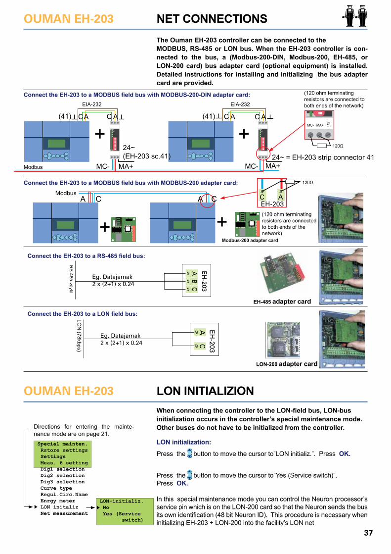
37
OUMAN EH-203
OUMAN EH-203
NET CONNECTIONS
LON INITIALIZION
The Ouman EH-203 controller can be connected to the MODBUS, RS-485 or LON bus. When the EH-203 controller is con-nected to the bus, a (Modbus-200-DIN, Modbus-200, EH-485, or LON-200 card) bus adapter card (optional equipment) is installed. Detailed instructions for installing and initializing the bus adapter card are provided.
When connecting the controller to the LON-field bus, LON-bus initialization occurs in the controller’s special maintenance mode. Other buses do not have to be initialized from the controller.
LON initialization:
Press the button to move the cursor to”LON initializ.”. Press OK.
Directions for entering the mainte-nance mode are on page 21.
LON-initializ. No Yes (Service switch)
Special mainten. Rstore settings Settings Meas. 6 setting Dig1 selection Dig2 selection Dig3 selection Curve type Regul.Circ.Name Enrgy meter LON initaliz Net measurement
Press the button to move the cursor to”Yes (Service switch)”. Press OK.
In this special maintenance mode you can control the Neuron processor’s service pin which is on the LON-200 card so that the Neuron sends the bus its own identification (48 bit Neuron ID). This procedure is necessary when initializing EH-203 + LON-200 into the facility’s LON net
Connect the EH-203 to a RS-485 field bus:
Connect the EH-203 to a LON field bus:
AB
EH
-203
Eg. Datajamak2 x (2+1) x 0.24 C
RS-485-väylä
AC
EH
-203
Eg. Datajamak2 x (2+1) x 0.24
LON
(78kbps)
EH-485 adapter card
LON-200 adapter card
Connect the EH-203 to a MODBUS field bus with MODBUS-200-DIN adapter card:
MC- MC-MA+ MA+
+ +Modbus
EIA-232 EIA-232
24~ = EH-203 strip connector 41
(120 ohm terminating resistors are connected to both ends of the network)
24~ (EH-203 sc.41)
(41) (41)AC C A AC C AMC- MA+ 24
~
120Ω
A AC
Connect the EH-203 to a MODBUS field bus with MODBUS-200 adapter card:
Modbus-200 adapter card+ +
Modbus
(120 ohm terminating resistors are connected to both ends of the network)
C ACEH-203
120Ω
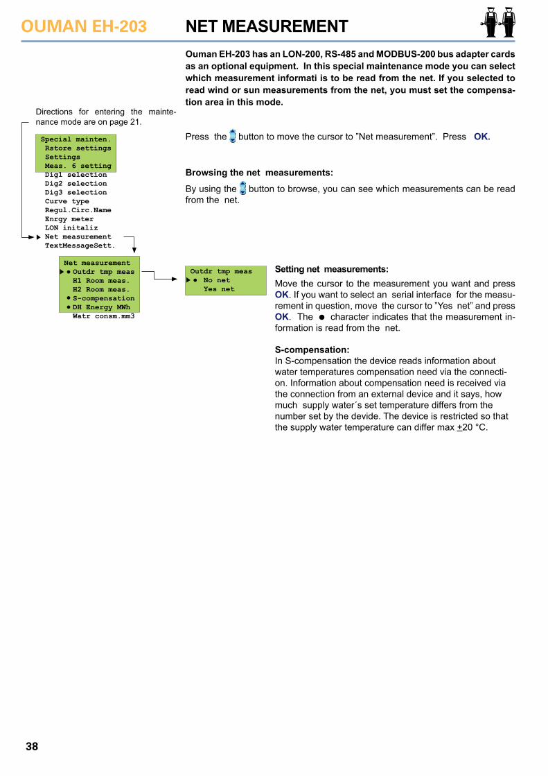
OUMAN EH-203
38
Move the cursor to the measurement you want and press OK. If you want to select an serial interface for the measu-rement in question, move the cursor to ”Yes net” and press OK. The character indicates that the measurement in-formation is read from the net.
Browsing the net measurements:
By using the button to browse, you can see which measurements can be read from the net.
Directions for entering the mainte-nance mode are on page 21.
Special mainten. Rstore settings Settings Meas. 6 setting Dig1 selection Dig2 selection Dig3 selection Curve type Regul.Circ.Name Enrgy meter LON initaliz Net measurement TextMessageSett.
Ouman EH-203 has an LON-200, RS-485 and MODBUS-200 bus adapter cards as an optional equipment. In this special maintenance mode you can select which measurement informati is to be read from the net. If you selected to read wind or sun measurements from the net, you must set the compensa-tion area in this mode.
Net measurement Outdr tmp meas H1 Room meas. H2 Room meas. S-compensation DH Energy MWh Watr consm.mm3
Outdr tmp meas No net Yes net
Press the button to move the cursor to ”Net measurement”. Press OK.
S-compensation:In S-compensation the device reads information about water temperatures compensation need via the connecti-on. Information about compensation need is received via the connection from an external device and it says, how much supply water´s set temperature differs from the number set by the devide. The device is restricted so that the supply water temperature can differ max +20 °C.
Setting net measurements:
NET MEASUREMENT
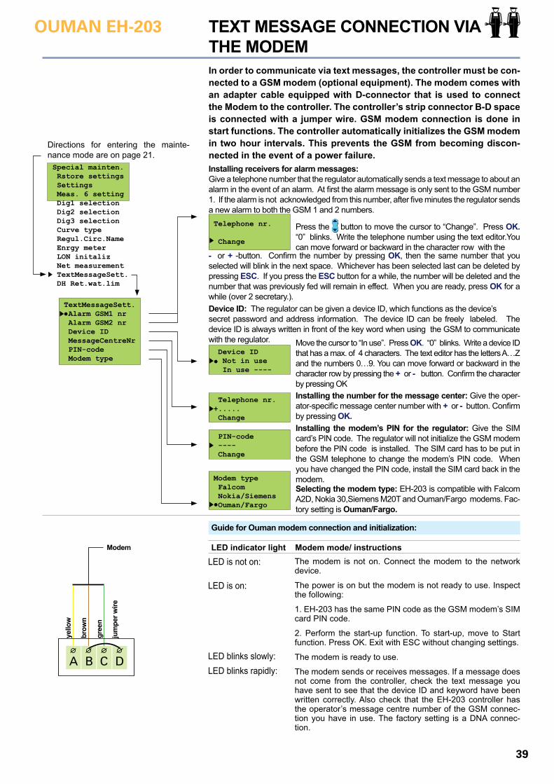
39
OUMAN EH-203 TEXT MESSAGE CONNECTION VIA THE MODEM
Directions for entering the mainte-nance mode are on page 21.Special mainten. Rstore settings Settings Meas. 6 setting Dig1 selection Dig2 selection Dig3 selection Curve type Regul.Circ.Name Enrgy meter LON initaliz Net measurement TextMessageSett. DH Ret.wat.lim
In order to communicate via text messages, the controller must be con-nected to a GSM modem (optional equipment). The modem comes with an adapter cable equipped with D-connector that is used to connect the Modem to the controller. The controller’s strip connector B-D space is connected with a jumper wire. GSM modem connection is done in start functions. The controller automatically initializes the GSM modem in two hour intervals. This prevents the GSM from becoming discon-nected in the event of a power failure.
TextMessageSett. Alarm GSM1 nr Alarm GSM2 nr Device ID MessageCentreNr PIN-code Modem type
Telephone nr. Change
PIN-code ---- Change
Modem type Falcom Nokia/Siemens Ouman/Fargo
Device ID Not in use In use ----
Telephone nr. +..... Change
Installing receivers for alarm messages: Give a telephone number that the regulator automatically sends a text message to about an alarm in the event of an alarm. At first the alarm message is only sent to the GSM number 1. If the alarm is not acknowledged from this number, after five minutes the regulator sends a new alarm to both the GSM 1 and 2 numbers.
Press the button to move the cursor to “Change”. Press OK. “0” blinks. Write the telephone number using the text editor.You can move forward or backward in the character row with the
- or + -button. Confirm the number by pressing OK, then the same number that you selected will blink in the next space. Whichever has been selected last can be deleted by pressing ESC. If you press the ESC button for a while, the number will be deleted and the number that was previously fed will remain in effect. When you are ready, press OK for a while (over 2 secretary.).Device ID: The regulator can be given a device ID, which functions as the device’s secret password and address information. The device ID can be freely labeled. The device ID is always written in front of the key word when using the GSM to communicate with the regulator. Move the cursor to “In use”. Press OK. “0” blinks. Write a device ID
that has a max. of 4 characters. The text editor has the letters A…Z and the numbers 0…9. You can move forward or backward in the character row by pressing the + or - button. Confirm the character by pressing OKInstalling the number for the message center: Give the oper-ator-specific message center number with + or - button. Confirm by pressing OK.Installing the modem’s PIN for the regulator: Give the SIM card’s PIN code. The regulator will not initialize the GSM modem before the PIN code is installed. The SIM card has to be put in the GSM telephone to change the modem’s PIN code. When you have changed the PIN code, install the SIM card back in the modem.Selecting the modem type: EH-203 is compatible with Falcom A2D, Nokia 30,Siemens M20T and Ouman/Fargo modems. Fac-tory setting is Ouman/Fargo.
Guide for Ouman modem connection and initialization:
DA CB
yello
w
brow
n
gree
n
jum
per w
ire
Modem LED indicator light Modem mode/ instructionsThe modem is not on. Connect the modem to the network device.
The power is on but the modem is not ready to use. Inspect the following:
1. EH-203 has the same PIN code as the GSM modem’s SIM card PIN code.
2. Perform the start-up function. To start-up, move to Start function. Press OK. Exit with ESC without changing settings.
The modem is ready to use.
The modem sends or receives messages. If a message does not come from the controller, check the text message you have sent to see that the device ID and keyword have been written correctly. Also check that the EH-203 controller has the operator’s message centre number of the GSM connec-tion you have in use. The factory setting is a DNA connec-tion.
LED is not on:
LED is on:
LED blinks slowly:LED blinks rapidly:
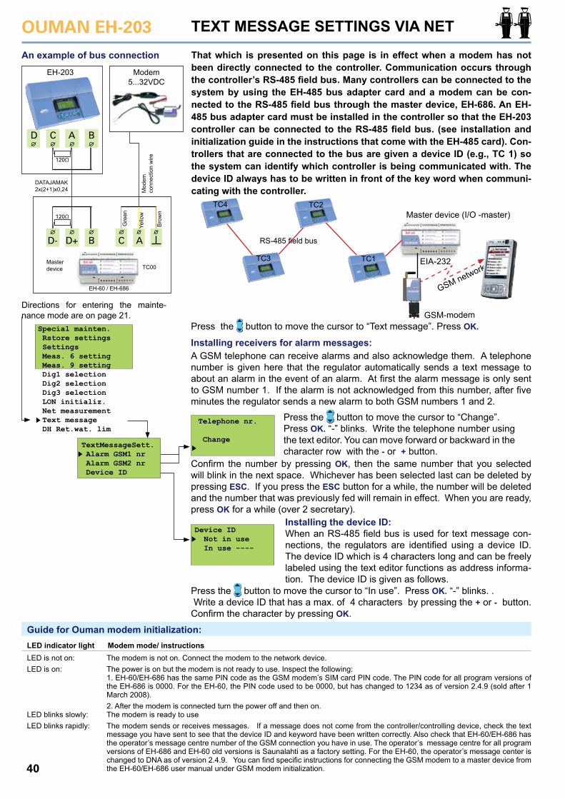
OUMAN EH-203
40
C AD-
CD
D+
A
B
B
120Ω
120Ω
Yello
w
Bro
wn
Gre
en
TEXT MESSAGE SETTINGS VIA NET
That which is presented on this page is in effect when a modem has not been directly connected to the controller. Communication occurs through the controller’s RS-485 field bus. Many controllers can be connected to the system by using the EH-485 bus adapter card and a modem can be con-nected to the RS-485 field bus through the master device, EH-686. An EH-485 bus adapter card must be installed in the controller so that the EH-203 controller can be connected to the RS-485 field bus. (see installation and initialization guide in the instructions that come with the EH-485 card). Con-trollers that are connected to the bus are given a device ID (e.g., TC 1) so the system can identify which controller is being communicated with. The device ID always has to be written in front of the key word when communi-cating with the controller.
Masterdevice
An example of bus connection
Mod
em
conn
ectio
n w
ire
DATAJAMAK2x(2+1)x0,24
EH-60 / EH-686
TC00
EH-203 Modem5...32VDC
Press the button to move the cursor to “Text message”. Press OK.
Installing receivers for alarm messages: A GSM telephone can receive alarms and also acknowledge them. A telephone number is given here that the regulator automatically sends a text message to about an alarm in the event of an alarm. At first the alarm message is only sent to GSM number 1. If the alarm is not acknowledged from this number, after five minutes the regulator sends a new alarm to both GSM numbers 1 and 2.
Special mainten. Rstore settings Settings Meas. 6 setting Meas. 9 setting Dig1 selection Dig2 selection Dig3 selection LON initializ. Net measurement Text message DH Ret.wat. lim
TextMessageSett. Alarm GSM1 nr Alarm GSM2 nr Device ID
Telephone nr. Change
Press the button to move the cursor to “Change”. Press OK. “-” blinks. Write the telephone number using the text editor. You can move forward or backward in the character row with the - or + button.
Confirm the number by pressing OK, then the same number that you selected will blink in the next space. Whichever has been selected last can be deleted by pressing ESC. If you press the ESC button for a while, the number will be deleted and the number that was previously fed will remain in effect. When you are ready, press OK for a while (over 2 secretary).
Installing the device ID: When an RS-485 field bus is used for text message con-nections, the regulators are identified using a device ID. The device ID which is 4 characters long and can be freely labeled using the text editor functions as address informa-tion. The device ID is given as follows.
Device ID Not in use In use ----
Press the button to move the cursor to “In use”. Press OK. “-” blinks. . Write a device ID that has a max. of 4 characters by pressing the + or - button. Confirm the character by pressing OK.
Guide for Ouman modem initialization:
The modem is not on. Connect the modem to the network device. The power is on but the modem is not ready to use. Inspect the following:1. EH-60/EH-686 has the same PIN code as the GSM modem’s SIM card PIN code. The PIN code for all program versions of the EH-686 is 0000. For the EH-60, the PIN code used to be 0000, but has changed to 1234 as of version 2.4.9 (sold after 1 March 2008). 2. After the modem is connected turn the power off and then on. The modem is ready to use The modem sends or receives messages. If a message does not come from the controller/controlling device, check the text message you have sent to see that the device ID and keyword have been written correctly. Also check that EH-60/EH-686 has the operator’s message centre number of the GSM connection you have in use. The operator’s message centre for all program versions of EH-686 and EH-60 old versions is Saunalahti as a factory setting. For the EH-60, the operator’s message center is changed to DNA as of version 2.4.9. You can find specific instructions for connecting the GSM modem to a master device from the EH-60/EH-686 user manual under GSM modem initialization.
LED indicator light Modem mode/ instructionsLED is not on:LED is on:
LED blinks slowly:LED blinks rapidly:
Master device (I/O -master)
EIA-232
TC4
TC3
TC2
TC1
RS-485 field bus
GSM network
GSM-modemDirections for entering the mainte-nance mode are on page 21.
OUMAN EH-203
41
Special mainten. Rstore settings Settings Meas. 6 setting Meas. 9 setting Dig1 selection Dig2 selection Dig3 selection LON initializ. Net measurement Text message DH Ret.wat.lim
DH Ret.wat. lim. H1 CompRatio 0.0 H2 CompRatio 0.0 RetWatMax-20 40 RetWatMax 0 50 RetWatMax+20 60
Directions for entering the mainte-nance mode are on page 21.
DISTRICT HEATING’S RETURN WATER TEMPERATURE LIMITINGIf you need to ensure that the water returning to the district heating centre is not too hot, set maximum return water temperatures for different outdoor temperatures. If the return water temperature ex-ceeds the set temperature limits, the controller will drop the return water temperature.
Setting Factorysetting
ExplanationRange
H1 CompRatio H2 CompRatio
RetWatMax-20
RetWatMax 0
RetWatMax+20
The compensation ratio for district heating’s return water limiting. If the return water temperature rises above the maximum limit the controller lowers the supply water temperature. The formula for the amount of the supply water temperature drop is: (“Return water temperature” - “Return water maximum”) x “Comp.ratio.
Maximum return water temperature with an outdoor temperature of -20 °C or be-low
Maximum return water temperature with an outdoor temperature of 0 °C.
Maximum return water temperature with an outdoor temperature of +20 °C or above.
When the outdoor temperature is be-tween -20 - +20 the maximum tempera-ture change is linear. The value can be read from the line going between the points in the diagram above.
0.0 °C0.0 °C
40 °C
50 °C
60 °C
0.0...9.9 °C0.0...9.9 °C
5...95 °C
5...95 °C
5...95 °C
INFORMATION ABOUT SETTINGS:
+ 25
+20
+15
+10 Outdoor temp.
Return water temp.
-20°C +20 0
OUMAN EH-203
42
DATA LINKIt is easy to connect the EH-203 controller to a computer using a CC-PCDEV1 cable (optional equipment). Connect the jump cable directly to the computer’s COM-port and connect the wires to the controller’s bus con-nection strip connectors when the controller is unplugged. It is also pos-sible to make the connection using a DATAJAMAK cable. Make the connec-tion as follows:
A
EH
-203CB
12
34
5
98
76
Connecting the conroller to a PC using a CC-PCDEV1 cable:
yebrgr
PC’s COM port
GSM-modem cablenull modem cable
D
EH-203 controller
PC AC
B
12
34
5
98
76
RX 25314678
GNDTXDCDDTRDSRRTSCTS
D-9 connector (female)
Connecting the controller to a PC usinga DATAJAMAK cable:
Connector pin number
DATAJAMAK2x(2+1)x0,24
are connectedtogether at the PC end.
are connectedtogether at the PC end.
43
OUMAN EH-203 USING THE BROWSERThe EH-net server (optional equipment) makes it possible for Ouman to offer a Web-based remote control and monitoring solution. The EH-203 controller is connected to the Modbus using the MODBUS-200 or MODBUS-200-DIN adapter card (optional equipment). It is easy, inex-pensive and safe to link the EH-net server and devices connected to the Modbus to the internet using internet and data security packages produced by Ouman. When you buy the 3G internet and data security package you acquire the Ouman name service, top quality data secu-rity and expert services. If you have a broad band internet connection, just plug in the EH-net server to connect to the internet.
By using the browser it is possible to communicate with the EH-203 control-ler from any pc connected to the internet. Check your computer display to see, e.g., controller settings, measurements and alarms. If desired, users can be denied entry to certain functions.
If the controller gives off an alarm, alarm information can be transmitted by e-mail or text message via a GSM phone. A GSM modem must be con-nected to the EH-net server for alarm information to be transmitted to a GSM phone.
Specific instructions for installing the MODBUS into the EH-203 controller and initialization come with the bus adapter card. Instructions for network connections and initialization come with the EH-net. Ouman’s product devel-opment invests in developing remote control solutions. Check out the newest recommendations and information about remote use at www.ouman.fi.
EH-netweb server Alarm transfer
Alarm transfer
Modbus
Text message to aGSM phone
Device-X
EH-203 EH-105 MODBUS-600 + EH-686
Internet/Intranet
OUMAN EH-203
44
INSTALLATION AND MAINTENANCE GUIDE
Switch off the voltage from the regul. Press the fuse socket and turn it coun-terclockwise. Change the 200mA (5x20mm) glass tube fuse. Press and turn the fuse socket clockwise into place.
Changing the fuse:
EH-203 has a backup that saves the time and time program in case of a short power failure. If the time is not correct after the power failure, the bat-tery must be changed. Battery type: Lithium button battery CR 1220, 3V. Unfasten the regulator’s fuse (see the topmost picture). Carefully pry the old battery from its holder, for eg., with a thin screw driver. Push the new bat-tery into the holder with the + end up. The old battery can be put into the gar-bage.
Changing the battery:
Spacers:
The cables can be routed between the regulator and installation base when spacers are used to mount the regula-tor.
Plugs:
Complete installation by pressing the plastic plugs into the screw holes.
EH-203 is fastened to its mounting base with three screws (two mounting points under the cover in the connection space and one in the installation bracket.Cables can be brought for the regulator from above (standard factory deliv-ery) or from below. In addition, there are 6 cable through-holes in the bottom of the regulator case which can be opened, e.g., with a screw driver. Then the cables can be brought into the connection space through the bottom.
Cabling from above: (standard factory delivery)
Cabling from below: (turn the keyboard/display unit)
Mounting guide:Screw the regulator to the wall using the installation bracket. Positionthe unit so it is level. Screw the regulator firmly into place using twoscrews through the connection space.
Installation bracket
If you want to bring the cables to the regulator from below, you must turn the keyboard/display unit according to the following instructions.
Changing the cabling direction:
Remove the clear cover. Press as illus-trated in the picture and pull the cover out of place.
Detach the keyboard/display unit carefully by prying it with a screwdriver.
Turn the keyboard/display unit into the opposite position.
Press the keyboard/display unit carefully into place.
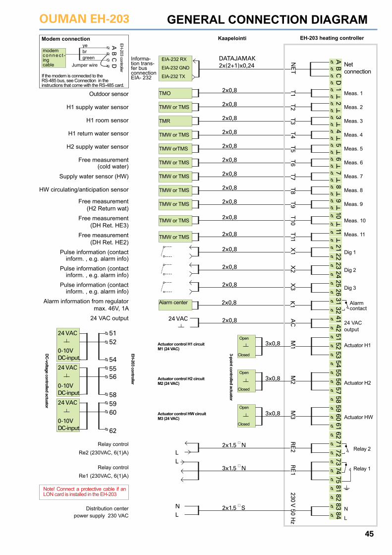
OUMAN EH-203
45
INSTALLATION AND MAINTENANCE GUIDE
5556
58
AB
CD
12
34
56
78
910
1121
2223
2425
2631
3241
4254
5556
5758
5960
6162
7172
7374
7581
8283
84DATAJAMAK2x(2+1)x0,24 Net
connection
NE
T2x0,8 T
12x0,8 T
2
2x0,8 T3
2x0,8 T4
2x0,8 T5
2x0,8 T6
2x0,8 T7
2x0,8 T8
2x0,8 T9
2x0,8
T10
2x0,8
T11
2x0,8
X1
2x0,8
X2
2x0,8
X3
2x0,8
K1
2x0,8
AC24 VAC
5152
53
3x0,8
M1
3x0,8
M2
3x0,8
M3
5152
54
5960
62
24 VAC
0-10VDC-input.
0-10VDC-input
24 VAC
0-10VDC-input
24 VAC
2x1.5 N
RE
2
L
2x1.5 S
230 V 50 H
z
L
3x1.5 N
RE
1
L
N
GENERAL CONNECTION DIAGRAM Modem connection
If the modem is connected to the RS-485 bus, see Connection in the instructions that come with the RS-485 card.
AB
CD
modem connec t -ing cable
EH-203 controller
yebrgreen
Jumper wireEIA-232 RX
EIA-232 GND
EIA-232 TX
TMO
TMW or TMS
TMR
TMW or TMS
TMW orTMS
TMW or TMS
TMW or TMS
TMW or TMS
TMW or TMS
TMW or TMS
TMW or TMS
Alarm center
Meas. 1
Meas. 2
Meas. 3
Meas. 4
Meas. 5
Meas. 6
Meas. 7
Meas. 8
Meas. 9
Meas. 10
Meas. 11
Dig 1
Dig 2
Dig 3
Alarm contact
24 VACoutput
Actuator H1
Actuator H2
Actuator HW
Relay 2
Relay 1
N
L
Outdoor sensor
H1 supply water sensor
H1 room sensor
H1 return water sensor
H2 supply water sensor
Free measurement(cold water)
Supply water sensor (HW)
HW circulating/anticipation sensor
Free measurement(H2 Return wat)
Free measurement(DH Ret. HE3)
Free measurement(DH Ret. HE2)
Pulse information (contact inform. , e.g. alarm info)
Pulse information (contact inform. , e.g. alarm info)
Pulse information (contact inform. , e.g. alarm info)
Alarm information from regulator max. 46V, 1A
24 VAC output
Kaapelointi
Informa-tion trans-fer bus connection EIA- 232
EH-203 heating controller
EH-203 controller
DC-voltage controlled actuator
3-point controlled actuator
Open
Open
Open
Closed
Closed
Closed
Actuator control H1 circuitM1 (24 VAC)
Actuator control H2 circuitM2 (24 VAC)
Relay controlRe2 (230VAC, 6(1)A)
Relay controlRe1 (230VAC, 6(1)A)
Distribution center power supply 230 VAC
Actuator control HW circuitM3 (24 VAC)
Note! Connect a protective cable if an LON card is installed in the EH-203
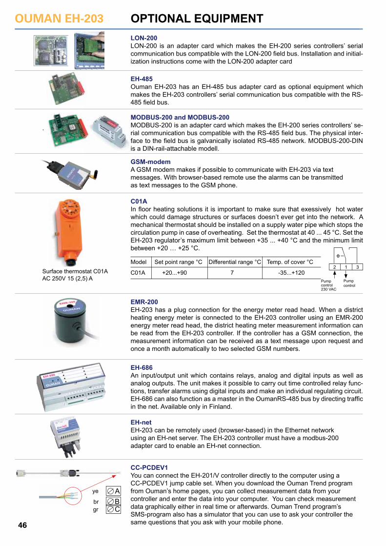
OUMAN EH-203
46
OPTIONAL EQUIPMENTLON-200LON-200 is an adapter card which makes the EH-200 series controllers’ serial communication bus compatible with the LON-200 field bus. Installation and initial-ization instructions come with the LON-200 adapter card
EH-485Ouman EH-203 has an EH-485 bus adapter card as optional equipment which makes the EH-203 controllers’ serial communication bus compatible with the RS-485 field bus.
MODBUS-200 and MODBUS-200MODBUS-200 is an adapter card which makes the EH-200 series controllers’ se-rial communication bus compatible with the RS-485 field bus. The physical inter-face to the field bus is galvanically isolated RS-485 network. MODBUS-200-DIN is a DIN-rail-attachable modell.
GSM-modemA GSM modem makes if possible to communicate with EH-203 via text messages. With browser-based remote use the alarms can be transmitted as text messages to the GSM phone.
C01AIn floor heating solutions it is important to make sure that exessively hot water which could damage structures or surfaces doesn’t ever get into the network. A mechanical thermostat should be installed on a supply water pipe which stops the circulation pump in case of overheating. Set the thermostat at 40 ... 45 °C. Set the EH-203 regulator’s maximum limit between +35 ... +40 °C and the minimum limit between +20 … +25 °C.
EMR-200EH-203 has a plug connection for the energy meter read head. When a district heating energy meter is connected to the EH-203 controller using an EMR-200 energy meter read head, the district heating meter measurement information can be read from the EH-203 controller. If the controller has a GSM connection, the measurement information can be received as a text message upon request and once a month automatically to two selected GSM numbers.
EH-686An input/output unit which contains relays, analog and digital inputs as well as analog outputs. The unit makes it possible to carry out time controlled relay func-tions, transfer alarms using digital inputs and make an individual regulating circuit. EH-686 can also function as a master in the OumanRS-485 bus by directing traffic in the net. Available only in Finland.
EH-netEH-203 can be remotely used (browser-based) in the Ethernet network using an EH-net server. The EH-203 controller must have a modbus-200 adapter card to enable an EH-net connection.
CC-PCDEV1You can connect the EH-201/V controller directly to the computer using a CC-PCDEV1 jump cable set. When you download the Ouman Trend program from Ouman’s home pages, you can collect measurement data from your controller and enter the data into your computer. You can check measurementdata graphically either in real time or afterwards. Ouman Trend program’s SMS-program also has a simulator that you can use to ask your controller the same questions that you ask with your mobile phone.
Pump control230 VAC
Pump control
2 1 3
0
-35...+120
Model
C01A +20...+90 7
Set point range °C Differential range °C Temp. of cover °CSurface thermostat C01A AC 250V 15 (2,5) A
ABC
ye
brgr
OUMAN EH-203
47
INDEX
3-point charac. heating curve 4,5,345-point charac. heating curve 4,5,34
Actuator control mode 25Actuator selection 25Alarms 18, 32-33Alarm labeling 33Alarms directed to a GSM 39, 40Alternate pump 27Anti-bakteria function 14, 23Anticipation function 9, 22Approvals 44Automatic control 12Autumn drying 7
Backup pump 27Battery changing 44Browser using 43Burner control 7, 26Bus adapter card 37, 46
Cabling 44Characteristic heating curve type selection 34Circulat. pump summer stop.7, 26Clock programs 14-15Consumption alarm 33, 18Connection instruction 45
Data link 42Deviation alarm 18Deviation alarm delay 29Device ID 37, 38DH’s return water temp. limiting 41DH energy consumption 9, 11, 33DH output limiting 29, 33DH water flow limiting 29, 33DH water consumption 9, 29, 33Digital inputs 32-33District heating energy meas. 11Door locks 14, 15
E-compensation 6, 9, 30EH-net 39, 43, 46EMR-200 11, 46Exhaust fan ½- speed 29, 32-33Energy consumption 9, 11, 32-33Energy meter 11, 36
Field bus 38, 40Fill alarm 31Floor heating 5Forced mode 12, 15Fuse changing 44 Freeze protect limit 29Freezing risk alarm 18
GSM-modem 39, 40, 46GSM-functions 19
Heating curve setting 4, 5Heating network pressure alarm 31Heating pump control 26, 27Heating resistor control 27Home/away switch 33, 10 HW overheating alarm 18HW overheating alarm delay 29HW temperature increase 12, 14HW temperature setting 7
Input/Output unit 39, 46Installation instructions 44
Labelling regulating circuits 35Language change 16Leakage alarm 31, 32LON-bus adapter card 37, 46LON initialization 37
Manual operation 12Maximum limit (supply water) 6Measurements 8, 9,11, 30, 31, 38Measurements labeling 8Minimum limit (supply water) 6Modem connection 39, 40MODBUS-200 37, 43, 46
Name change 8, 32-33, 35Net measurements 38Night drop 6, 10, 33Nominal temperature 12
Outdoor temperature 9, 38Outdoor temperature delay 23Overcurrent protection 33
Parallel pump 27, 33Parallel shift 5, 6PID regulation 22Preheating for air conditioning 5Pre-increase 7Pre-increase time 23Pressure alarm 18, 31Protection class 48Pulse information 32Pump control 26, 27Pump’s thermal relay 27, 33Pump summer stop 7, 26
Relay controls 15, 26, 27Relay controls labeling 26, 27Restoring settings 28Return water maximum 29Return water minimum 29Room compensation 6, 30Room temperature delay 29 RS-485 bus 40, 46
Sauna stove 15, 26, 27S-compensation 38Self-learning 17Sensor fault alarm 18Stand by-function 12, 10, 29Start function 17Sun compensation 7, 38Supply water temperature info 10Surface mounted thermostat 5
Technical information 48Temperature drop 12, 14Temperature operated relay 26Time controls 14, 15Timer functions 15Text editor 8Text message use 19Text message settings 39, 40Trend display 24Tuning 22Type information 16
Valve flush function 20Valve summer stop 7, 26
Waste water tank alarm 18Water limit 29Water pressure alarm 31, 18Wind compensation 30
The enclosed marking on the additional material of the product indicates that this product must not be disposed of together with household waste at the end of its life span. The product must be proces-sed separately from other waste to prevent dama-ge caused by uncontrolled waste disposal to the environment and the health of fellow human beings. The users must contact the retailer responsible for having sold the product, the supplier or a local environmental authority, who will provide additional informa-tion on safe recycling opportunities of the product. This product must not be disposed of together with other commercial waste.
Disposing of the EH-800 controller:
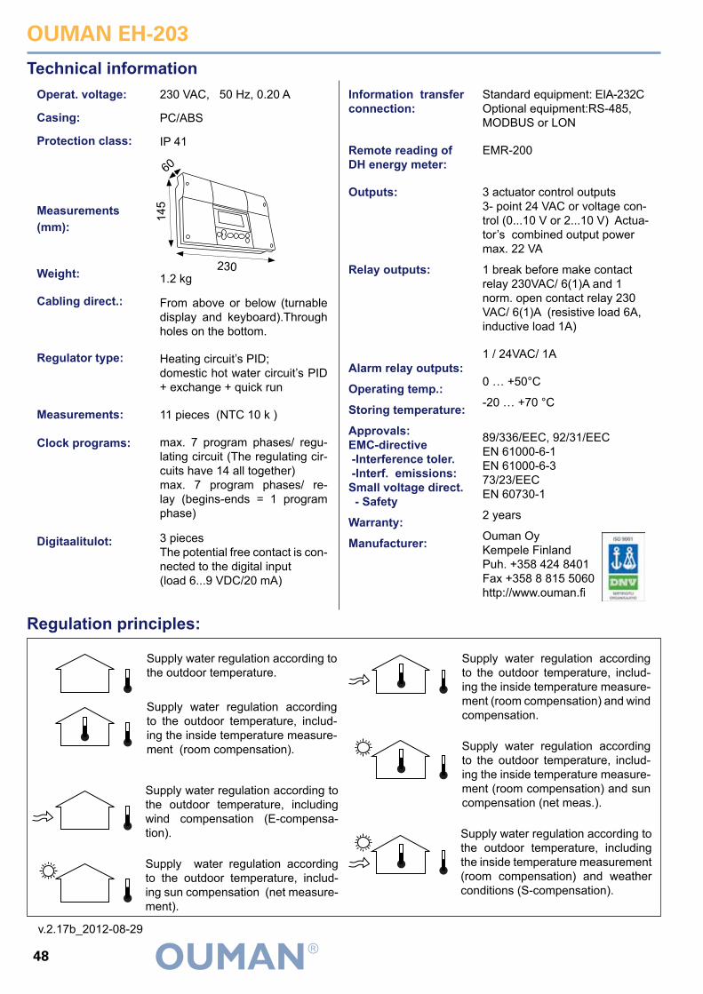
OUMAN EH-203
48
Technical informationStandard equipment: EIA-232C Optional equipment:RS-485, MODBUS or LON
EMR-200
3 actuator control outputs 3- point 24 VAC or voltage con-trol (0...10 V or 2...10 V) Actua-tor’s combined output power max. 22 VA
1 break before make contact relay 230VAC/ 6(1)A and 1 norm. open contact relay 230 VAC/ 6(1)A (resistive load 6A, inductive load 1A)
1 / 24VAC/ 1A
0 … +50°C
-20 … +70 °C
89/336/EEC, 92/31/EEC EN 61000-6-1EN 61000-6-373/23/EECEN 60730-1
2 years
Ouman Oy Kempele Finland Puh. +358 424 8401 Fax +358 8 815 5060 http://www.ouman.fi
Operat. voltage:
Casing:
Protection class:
Measurements (mm):
Weight:
Cabling direct.:
Regulator type:
Measurements:
Clock programs:
Digitaalitulot:
Information transfer connection:
Remote reading of DH energy meter:
Outputs:
Relay outputs:
Alarm relay outputs:
Operating temp.:
Storing temperature:
Approvals: EMC-directive -Interference toler. -Interf. emissions:Small voltage direct. - Safety
Warranty:
Manufacturer:
Regulation principles:
230 VAC, 50 Hz, 0.20 A
PC/ABS
IP 41
1.2 kg
From above or below (turnable display and keyboard).Through holes on the bottom.
Heating circuit’s PID;domestic hot water circuit’s PID + exchange + quick run
11 pieces (NTC 10 k )
max. 7 program phases/ regu-lating circuit (The regulating cir-cuits have 14 all together)max. 7 program phases/ re-lay (begins-ends = 1 program phase)
3 pieces The potential free contact is con-nected to the digital input(load 6...9 VDC/20 mA)
Supply water regulation according to the outdoor temperature.
Supply water regulation according to the outdoor temperature, includ-ing the inside temperature measure-ment (room compensation).
Supply water regulation according to the outdoor temperature, including wind compensation (E-compensa-tion).
Supply water regulation according to the outdoor temperature, includ-ing sun compensation (net measure-ment).
Supply water regulation according to the outdoor temperature, includ-ing the inside temperature measure-ment (room compensation) and wind compensation.
Supply water regulation according to the outdoor temperature, includ-ing the inside temperature measure-ment (room compensation) and sun compensation (net meas.).
Supply water regulation according to the outdoor temperature, including the inside temperature measurement (room compensation) and weather conditions (S-compensation).
6014
5
230
v.2.17b_2012-08-29