Embed Size (px)
Citation preview

1/1/2019
1
1
Calculation of Electromagnetic Fields Underneath A Proposed HVDC Transmission
Line Interconnected Egypt and KSA
A. Elmorshdya*, M. M. Samybc, and A. M. Emama
a Electrical Power and Machines Department, Faculty of Engineering, CairoUniversity, Giza, Egypt.b Electrical Engineering Department, Faculty of Industrial Education, Beni-SuefUniversity, Beni-Suef, Egypt.c Electrical Engineering Department, Faculty of engineering, Al-Baha University, Al-Baha, KSA.
*Corresponding Author Contacts: [email protected]
2
OUTLINES
� Objectives
�Historical Background
�Advantages of HVDC Transmission.
�Construction and Types of HVDC Lines
�The Proposed Line tying Egypt and KSA.
�Research Methodology
�Simulation results and discussions
� Conclusions

1/1/2019
2
3
Objectives
� The main objective of this presentation is to introducecalculating values for electromagnetic fields underneatha proposed HVDC transmission line tying Egypt and KSA.
� The Right Of Way (ROW) of the proposed line is tobe calculated.
� Two numerical methods are used for calculating bothelectric and magnetic fields. The Charge SimulationMethod (CSM) is used for electric field calculation, whilethe Current Simulation Technique (CST) is used formagnetic field calculation.
4
Historical Background
Electric power transmission was originally developed with
direct current.
The world's first DC transmission is supplied directly to the
DC load with a DC generator. 1882, French physicist Pule
used DC generators installed in Miesbach mine, with 1.5 ~
2.0kV voltages, along 57km of telegraph lines, supply the
electric power to the international exhibition held in Munich,
he completed the first ever DC transmission test.

1/1/2019
3
5
An early method of high voltage DC transmission was
developed by the Swiss engineer Rene Thury.
This system used series-connected motor generator sets to
increase voltage.
The line was operated in constant current mode, with up to 5
kV on each machine. An early example of this system was
installed in 1889 in Italy by the Acquedotto de Ferrari-
Galliera Company. This system transmitted 630 kW at 14 kV
DC over a distance of 120 km .
Historical Background (Cont.)
6
The first commercial HVDC line built in 1954 was a 98 km
submarine cable with ground return between the island of
Gotland and the Swedish mainland.
Thyristors were applied to DC transmission in the late 1960’s
and solid-state valves became a reality. In 1969, a contract
for the Eel River DC link in Canada was awarded as the first
application of solid state valves (diodes and thyristors) for
HVDC transmission.
Historical Background (Cont.)
1/1/2019
4
7
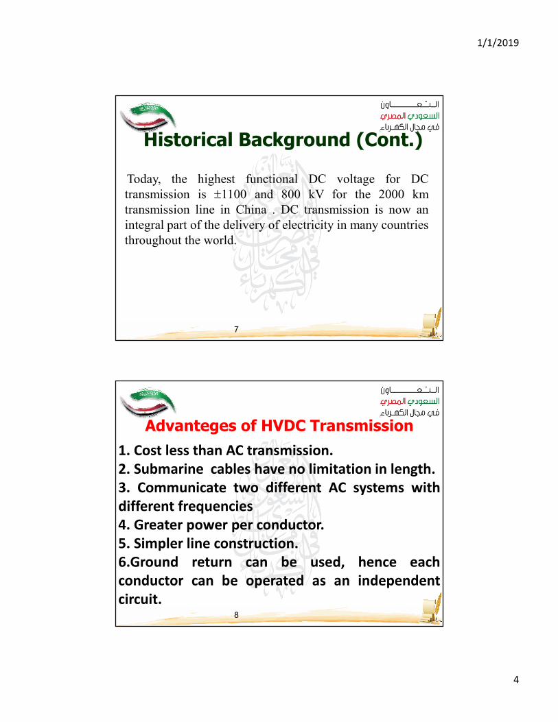
Today, the highest functional DC voltage for DC
transmission is ±1100 and 800 kV for the 2000 km
transmission line in China . DC transmission is now an
integral part of the delivery of electricity in many countries
throughout the world.
Historical Background (Cont.)
8
Advanteges of HVDC Transmission
1. Cost less than AC transmission.
2. Submarine cables have no limitation in length.
3. Communicate two different AC systems with
different frequencies
4. Greater power per conductor.
5. Simpler line construction.
6.Ground return can be used, hence each
conductor can be operated as an independent
circuit.
1/1/2019
5
9
Advanteges of HVDC Transmission (Cont.)
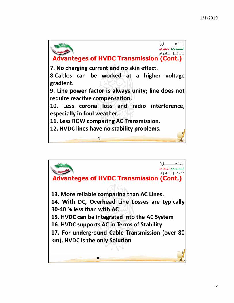
7. No charging current and no skin effect.
8.Cables can be worked at a higher voltage
gradient.
9. Line power factor is always unity; line does not
require reactive compensation.
10. Less corona loss and radio interference,
especially in foul weather.
11. Less ROW comparing AC Transmission.
12. HVDC lines have no stability problems.
10
Advanteges of HVDC Transmission (Cont.)
13. More reliable comparing than AC Lines.
14. With DC, Overhead Line Losses are typically
30-40 % less than with AC
15. HVDC can be integrated into the AC System
16. HVDC supports AC in Terms of Stability
17. For underground Cable Transmission (over 80
km), HVDC is the only Solution

1/1/2019
6
11
Advanteges of HVDC Transmission (Cont.)
12
Advanteges of HVDC Transmission (Cont.)

1/1/2019
7
13
14

1/1/2019
8
15
ACsystem
AC
system
CBT1 T2
Rectifier Inverter
Smoothinginductor
Construction of HVDC Line
Some writers claim that a two conductor dc line provides the same
reliability as a two circuit three phase line having six line conductors,
for either conductor of the dc line can be used with ground return
continuously or for limited periods, say, a few days per year.
16
Types of DC Links
1- The monopolar line (link) has one conductor, usually of negative
polarity, and ground or sea return
Negative
AC side AC side

1/1/2019
9
17
Types of DC Links (Cont.)2- The bipolar line (link) shown has two conductors one positive, the
other negative
Negative
Postive
AC side AC side
18
Types of DC Links (Cont.)
Negative
Negative
AC sideAC side
3- The homopolar line (link) shown in the following Figure. link has
two or more conductors all having the same polarity, usually negative,
and always operates with ground return
1/1/2019
10
19
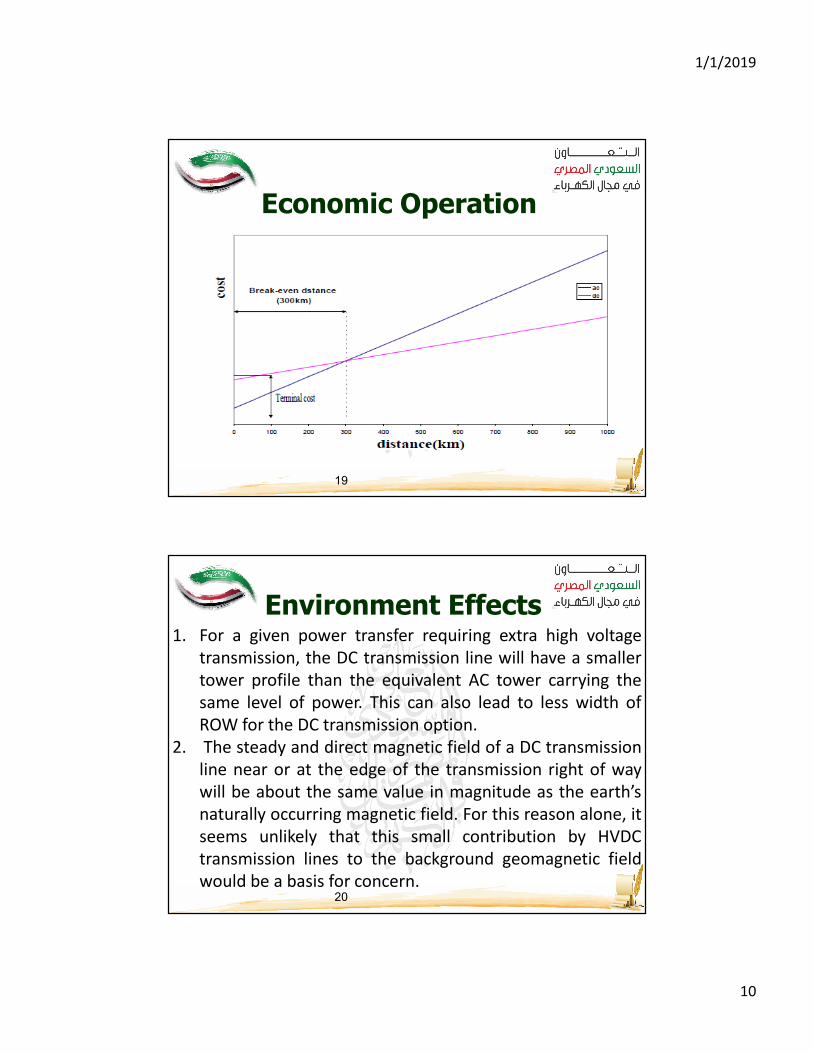
Economic Operation
20
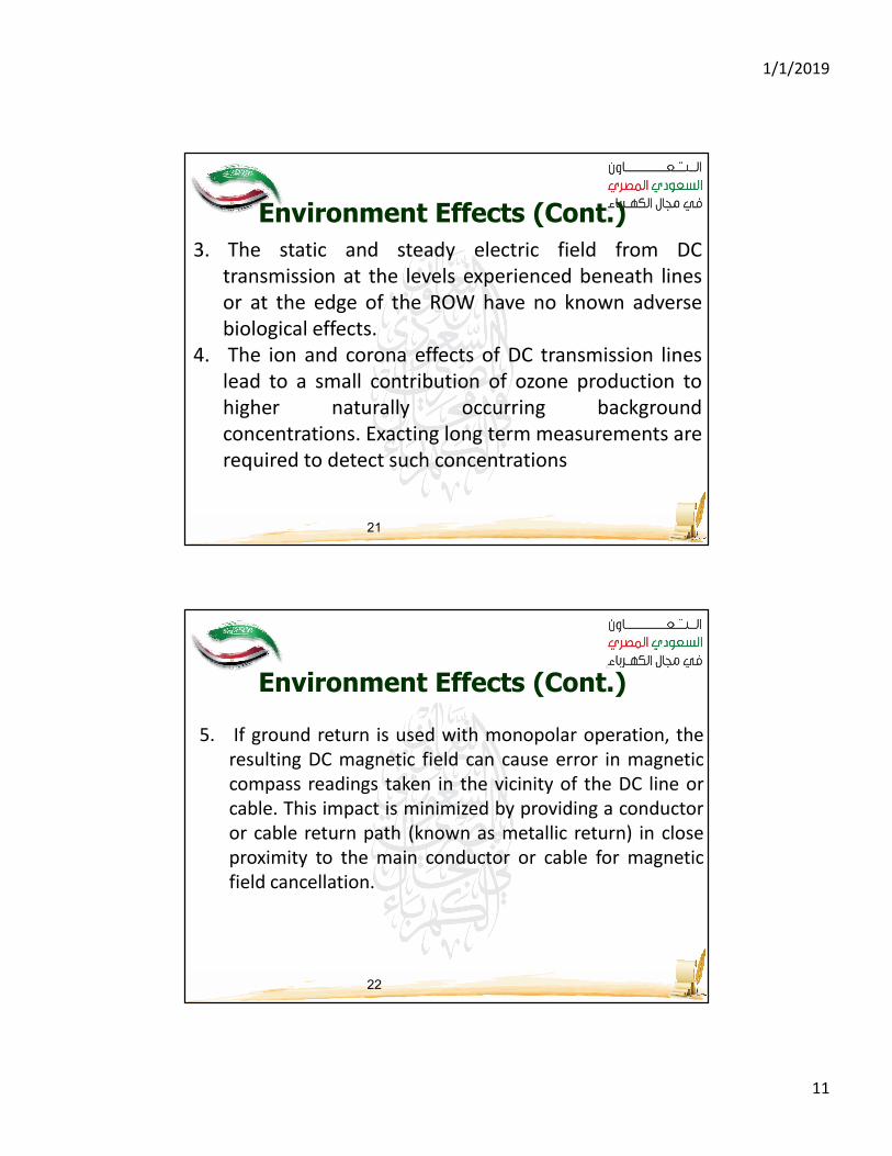
Environment Effects1. For a given power transfer requiring extra high voltage
transmission, the DC transmission line will have a smaller
tower profile than the equivalent AC tower carrying the
same level of power. This can also lead to less width of
ROW for the DC transmission option.
2. The steady and direct magnetic field of a DC transmission
line near or at the edge of the transmission right of way
will be about the same value in magnitude as the earth’s
naturally occurring magnetic field. For this reason alone, it
seems unlikely that this small contribution by HVDC
transmission lines to the background geomagnetic field
would be a basis for concern.
1/1/2019
11
21
Environment Effects (Cont.)
3. The static and steady electric field from DC
transmission at the levels experienced beneath lines
or at the edge of the ROW have no known adverse
biological effects.
4. The ion and corona effects of DC transmission lines
lead to a small contribution of ozone production to
higher naturally occurring background
concentrations. Exacting long term measurements are
required to detect such concentrations
22
5. If ground return is used with monopolar operation, the
resulting DC magnetic field can cause error in magnetic
compass readings taken in the vicinity of the DC line or
cable. This impact is minimized by providing a conductor
or cable return path (known as metallic return) in close
proximity to the main conductor or cable for magnetic
field cancellation.
Environment Effects (Cont.)
1/1/2019
12
23
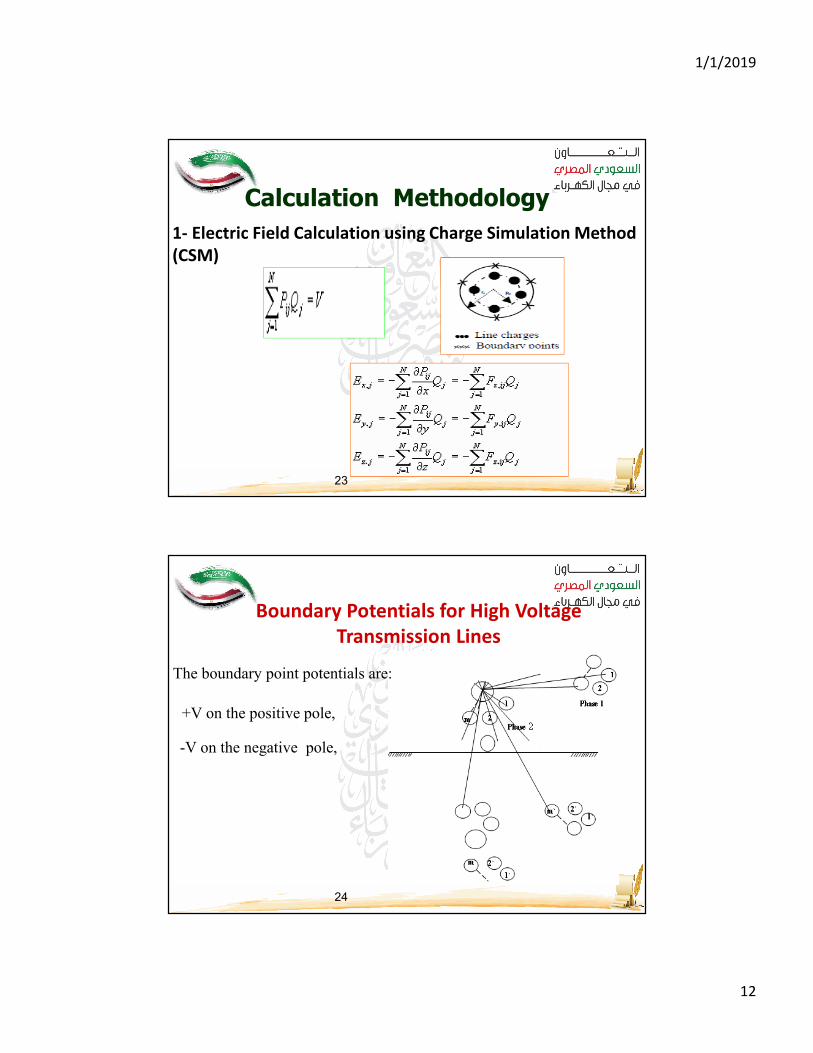
1- Electric Field Calculation using Charge Simulation Method
(CSM)
Calculation Methodology
24
Boundary Potentials for High Voltage
Transmission Lines
The boundary point potentials are:
+V on the positive pole,
-V on the negative pole,

1/1/2019
13
25
2- Magnetic Field Calculation using Current Simulation
Technique (CST)
)1(2.....,.........3,2,1,02
1
−==∑=
nmjipnm
k
kkj
mqIicq
nq
nqkk
2.....,.........3,2,1,1)1(
==∑+−=
where Pkj is the normal magnetic field coefficient determined by the coordinates of the
jth boundary point and the kth filamentary line current and is given by:
kj
kjl
kjP
θπ
sin2
1=
−+−
++−−
−+−
−+−−= ∑
=2222
1 )()(
)()(
)()(
)()(
2
1
kk
ykxk
kk
ykxknm
k
kyyxx
axxayy
yyxx
axxayyiH
π
jkjkj φαθ −=where
26
Results and Discussions
Typical construction of a ±500kV Transmission line

1/1/2019
14
27
-1000
-800
-600
-400
-200
0
200
400
600
800
1000
-100 -80 -60 -40 -20 0 20 40 60 80 100
Distance (m)
Ele
ctr
ic F
ield
(V
/m)
f(h=63m)
f(h=80m)
f(h=116m)
f(h=158m)
Typical Electric field values for ±500kV Transmission line at different heights
28
-10
-8
-6
-4
-2
0
2
4
6
8
10
-100 -80 -60 -40 -20 0 20 40 60 80 100
Mag
neti
c
field
den
sit
y (µ
T)
Distance (m)
b (h=63m)
b (h=80m)
b (h=116m)
b (h=158m)
Typical Magnetic field values for ±500kV Transmission line at different heights
1/1/2019
15
29
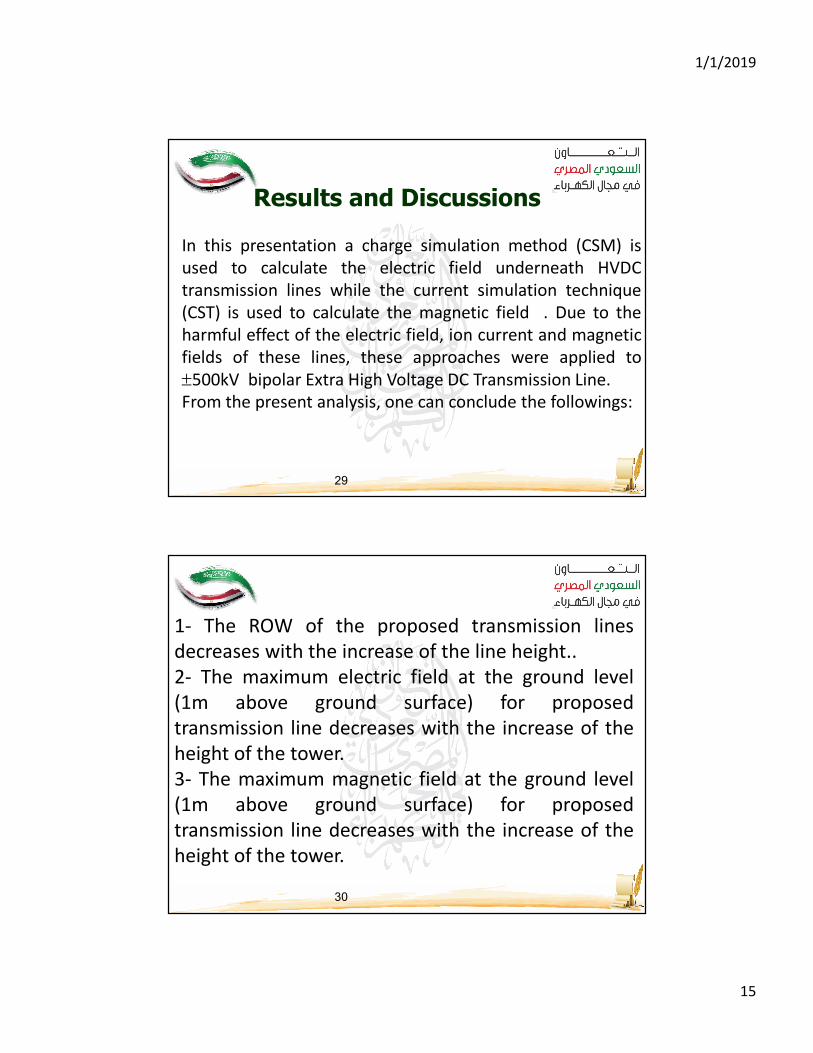
Results and Discussions
In this presentation a charge simulation method (CSM) is
used to calculate the electric field underneath HVDC
transmission lines while the current simulation technique
(CST) is used to calculate the magnetic field . Due to the
harmful effect of the electric field, ion current and magnetic
fields of these lines, these approaches were applied to
±500kV bipolar Extra High Voltage DC Transmission Line.
From the present analysis, one can conclude the followings:
30
1- The ROW of the proposed transmission lines
decreases with the increase of the line height..
2- The maximum electric field at the ground level
(1m above ground surface) for proposed
transmission line decreases with the increase of the
height of the tower.
3- The maximum magnetic field at the ground level
(1m above ground surface) for proposed
transmission line decreases with the increase of the
height of the tower.
1/1/2019
16
31
تم بحمد الله
32
Reference [1] http://www.energy.siemens.com/br/en/power-transmission/hvdc/hvdcclassic.htm
(March 2016)
[2] http://www.energy.siemens.com/br/en/power-transmission/hvdc/hvdcclassic.htm
(March 2016)
[3] https://en.wikipedia.org/wiki/Direct_current (March 2016)
[4] https://en.wikipedia.org/wiki/High-voltage_direct_current (March 2016)
[5] http://mentalfloss.com/article/30140/acdc-tesla%E2%80%93edison-feud (March
2016)
[6] http://www.safetytech.cn/1932.html (March 2016)
[7] http://www.safetytech.cn/1942.html (March 2016)
[8] http://new.abb.com/systems/hvdc/references/the-gotland-hvdc-link (April 2016)
[9] http://www.cepri.com/ (April 2016)
[10]http://xueshu.baidu.com/s?wd=paperuri%3A%286b70a4ef45a5daa1101d98882d4
16
108%29&filter=sc_long_sign&tn=SE_xueshusource_2kduw22v&sc_vurl=http%3A%2F%
2Fwww.doc88.com%2Fp-94351327681.html&ie=utf-8 (April 2016)
[11] http://www.doc88.com/p-508834633373.html (April 2016)
[12]HVDC transmission technology [M]. Wang GuanJie.ChongQing University Press,

1/1/2019
17
33
[13]http://datacenter.chinabyte.com/274/8877274.shtml (April 2016)
[14]Simulation of commutation failure in HVDC transmission system
[J].Yang Xiu.Vo1.34 NO.2.Feb.2008 (April 2016)
[15]Research on traveling wave protection of HVDC transmission lines
[D].Ai Lin. North China Electric Power University, 2002 (April 2016)
[16]AutoCAD2006 tutorial [M].Zhu Longzhu.Science Press, 2007 (April
2016) 41 [17]http://datacenter.chinabyte.com/274/8877274.shtml
(April 2016)
[18]Study on operation and control of HVDC-VSC transmission system
[M].Wang Zhaoan.Machinery Industry Press, 2000 (May 2016)
[19]Fundamentals of Electrical Engineering [M].Wen Buying. China
Electric Power Press, 2006 (May 2016)
[20]http://wenku.baidu.com/link?url=ZAWzu0BKugJX4X1xFmIlP5gGsBG
lc22aKOtEq_rb
5fmjkGXTQShGXmvmf0IEAZN7mN2w6vvBzWvZlKmd6wcCjETdvVp4L4Oj
Wr3HAM65I G (May 2016)