Embed Size (px)
Citation preview
CENTRORICERCHEFIAT
Fluid dynamics and Combustion Analysis
Frankfurt, 4 - 10 - 2004 Centro Ricerche Fiat is the sole owner of this document. It cannot be copied or given to third parties without permission.
TEAM OF WORK:
G. GIAFFREDA, C. VENEZIA
FIAT RESEARCH CENTRE
ENGINE ENGINEERING AND DEVELOPMENT DIVISION
FLUID DYNAMICS AND COMBUSTION ANALYSIS DEPARTMENT
GT-SUITE USERS CONFERENCE
FRANKFURT, OCTOBER 4TH 2004
EGR Transient Simulation of a Turbocharged
Diesel Engine using GT-Power
CENTRORICERCHEFIAT
Fluid dynamics and Combustion Analysis
Frankfurt, 4 - 10 - 2004 Centro Ricerche Fiat is the sole owner of this document. It cannot be copied or given to third parties without permission.
PRESENTATION OVERVIEW
� INTRODUCTION
� GT-POWER MODEL DESCRIPTION
� TRANSIENT OF THE EGR PERCENTAGE AT CONSTANT ENGINE SPEED AND LOAD
� TRANSIENT OF EGR AND LOAD AT CONSTANT ENGINE SPEED
� REMARKS AND CONCLUSIONS
2
CENTRORICERCHEFIAT
Fluid dynamics and Combustion Analysis
Frankfurt, 4 - 10 - 2004 Centro Ricerche Fiat is the sole owner of this document. It cannot be copied or given to third parties without permission.
INTRODUCTION
THE GROWING OF THE HIGH SPEED DI DIESEL TECHNOLOGY DURING THE LAST 5 YEARS
HAD ALLOWED THE MODERN DIESEL ENGINES TO REACH LEVELS OF PERFORMANCE AND
REFINEMENT JUST UNTHINKABLE IN THE MIDDLE OF THE LAST DECADE.
IN PARALLEL WITH THIS CONTINUOUS EVOLUTION OF PERFORMANCE, THE DIESEL ENGINE
MANUFACTURERS HAVE TO FACE A VERY IMPORTANT PROBLEM: THE LEGISLATORS
IMPOSE A DRASTIC REDUCTION IN POLLUTANT EMISSIONS FOR THE NEXT YEARS.
THIS PUSHES THE DIESEL COMMUNITY TO INVEST MORE AND MORE EFFORTS IN THIS
DIRECTION.
THE USE OF A MODERN 1D CODE LIKE GT-POWER COULD BE HELPFUL, ALLOWING A
BETTER UNDERSTANDING OF FLUID DYNAMICS PHENOMENA AT PART LOAD POINTS AND
DURING TRANSIENT PHASES. IN THIS SENSE, IT COULD GIVE SUPPORT TO ENGINE TESTING
AND CONTROL DEVELOPMENT.
3
CENTRORICERCHEFIAT
Fluid dynamics and Combustion Analysis
Frankfurt, 4 - 10 - 2004 Centro Ricerche Fiat is the sole owner of this document. It cannot be copied or given to third parties without permission.
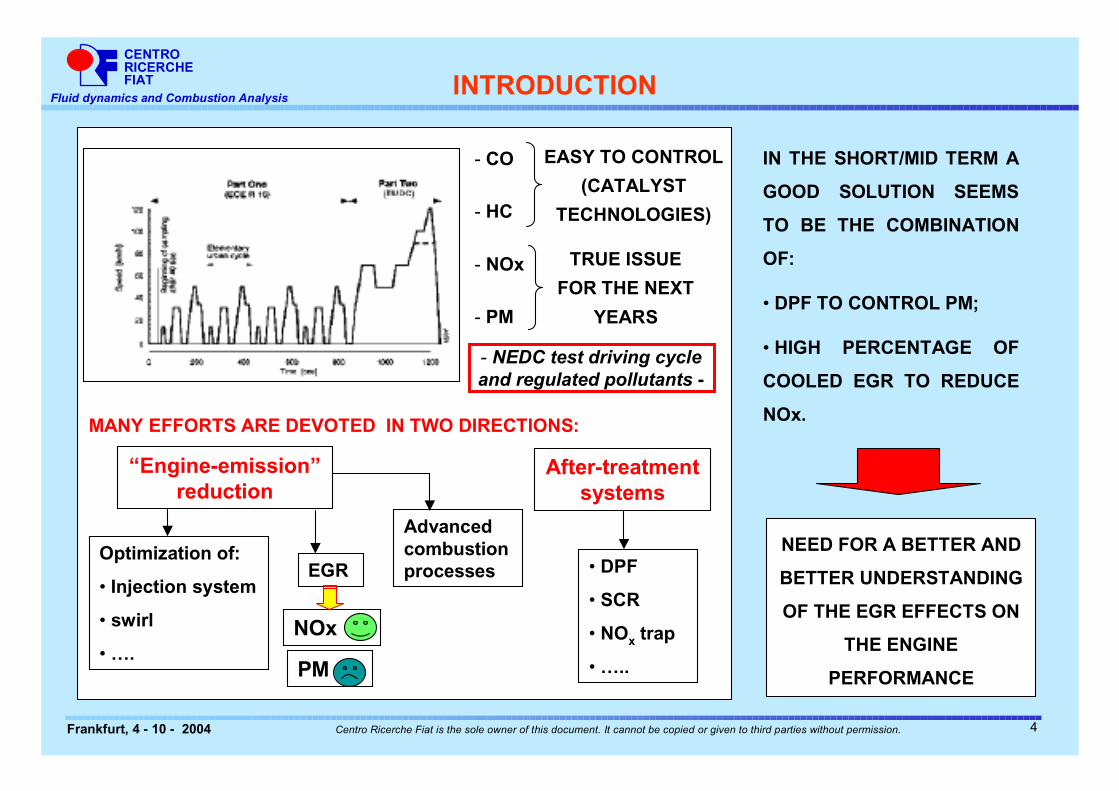
INTRODUCTION
IN THE SHORT/MID TERM A
GOOD SOLUTION SEEMS
TO BE THE COMBINATION
OF:
• DPF TO CONTROL PM;
• HIGH PERCENTAGE OF
COOLED EGR TO REDUCE
NOx.
EASY TO CONTROL
(CATALYST
TECHNOLOGIES)
- NEDC test driving cycle and regulated pollutants -
- CO
- HC
- NOx
- PM
TRUE ISSUE
FOR THE NEXT
YEARS
MANY EFFORTS ARE DEVOTED IN TWO DIRECTIONS:
“Engine-emission” reduction
After-treatment systems
Optimization of:
• Injection system
• swirl
• ….
Advanced combustion processesEGR • DPF
• SCR
• NOx trap
• …..PM
NOx
NEED FOR A BETTER AND
BETTER UNDERSTANDING
OF THE EGR EFFECTS ON
THE ENGINE
PERFORMANCE
4
CENTRORICERCHEFIAT
Fluid dynamics and Combustion Analysis
Frankfurt, 4 - 10 - 2004 Centro Ricerche Fiat is the sole owner of this document. It cannot be copied or given to third parties without permission.
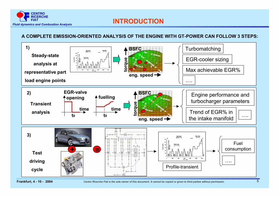
A COMPLETE EMISSION-ORIENTED ANALYSIS OF THE ENGINE WITH GT-POWER CAN FOLLOW 3 STEPS:
INTRODUCTION
Steady-state
analysis at
representative part
load engine points
torq
ue
eng. speed
BSFC
EGR-cooler sizing
Turbomatching
Max achievable EGR%
1)
….
Test
driving
cycle
+ =
Profile-transient
Fuel consumption
3)
….
Transient
analysis
fuelling
timet0 to
rqu
e
eng. speed
BSFC2) Engine performance and turbocharger parameters
Trend of EGR% in the intake manifold
….
EGR-valve opening
timet0
5
CENTRORICERCHEFIAT
Fluid dynamics and Combustion Analysis
Frankfurt, 4 - 10 - 2004 Centro Ricerche Fiat is the sole owner of this document. It cannot be copied or given to third parties without permission.
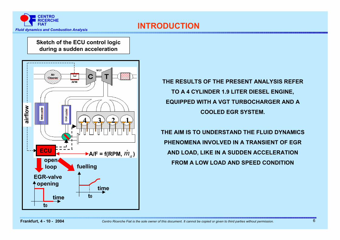
THE RESULTS OF THE PRESENT ANALYSIS REFER
TO A 4 CYLINDER 1.9 LITER DIESEL ENGINE,
EQUIPPED WITH A VGT TURBOCHARGER AND A
COOLED EGR SYSTEM.
THE AIM IS TO UNDERSTAND THE FLUID DYNAMICS
PHENOMENA INVOLVED IN A TRANSIENT OF EGR
AND LOAD, LIKE IN A SUDDEN ACCELERATION
FROM A LOW LOAD AND SPEED CONDITION
INTRODUCTION
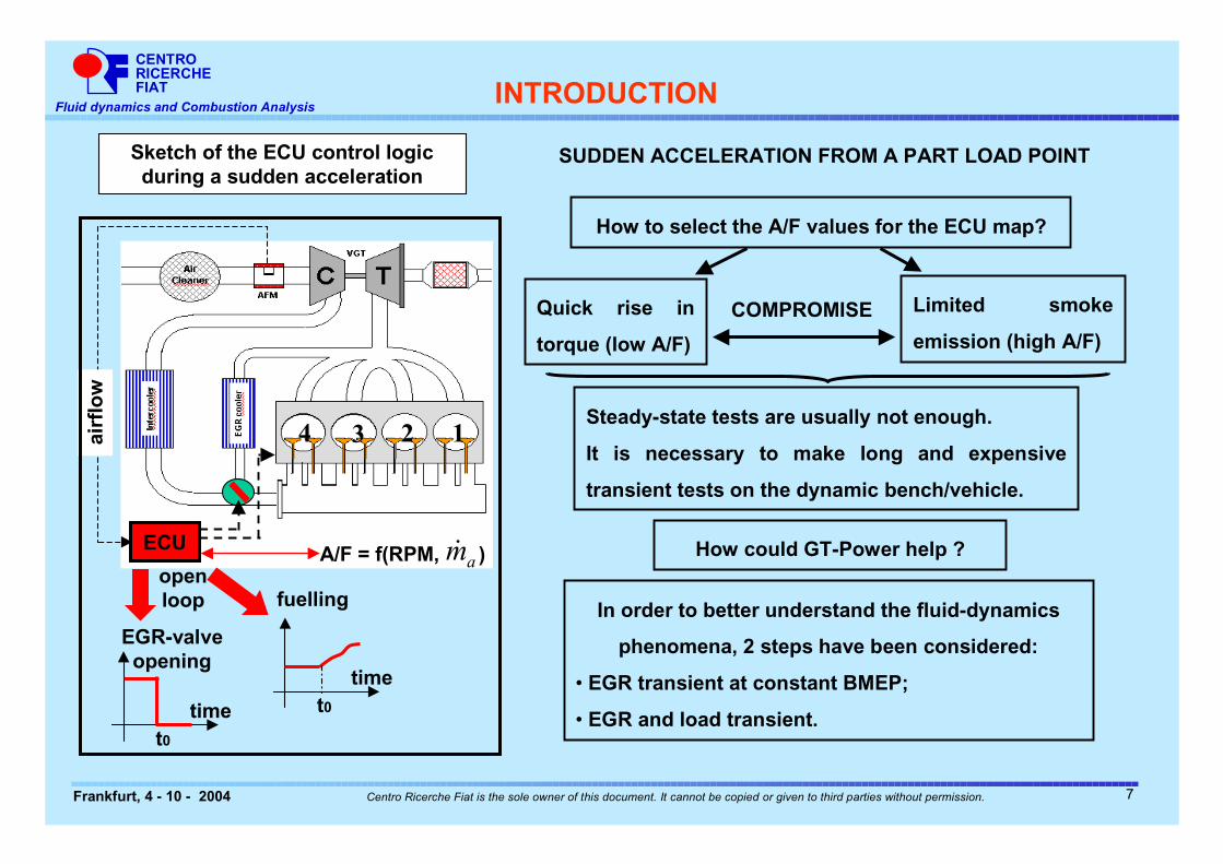
Sketch of the ECU control logic during a sudden acceleration
4 3 2 1
ECU
EGR-valve opening
timet0
fuelling
timet0
A/F = f(RPM, ) amÿ
airf
low
open loop
6
CENTRORICERCHEFIAT
Fluid dynamics and Combustion Analysis
Frankfurt, 4 - 10 - 2004 Centro Ricerche Fiat is the sole owner of this document. It cannot be copied or given to third parties without permission.
How to select the A/F values for the ECU map?
Quick rise in
torque (low A/F)
Limited smoke
emission (high A/F)
COMPROMISE
Steady-state tests are usually not enough.
It is necessary to make long and expensive
transient tests on the dynamic bench/vehicle.
How could GT-Power help ?
In order to better understand the fluid-dynamics
phenomena, 2 steps have been considered:
• EGR transient at constant BMEP;
• EGR and load transient.
SUDDEN ACCELERATION FROM A PART LOAD POINT
INTRODUCTION
Sketch of the ECU control logic during a sudden acceleration
4 3 2 1
ECU
EGR-valve opening
timet0
fuelling
timet0
A/F = f(RPM, ) amÿ
airf
low
open loop
7
CENTRORICERCHEFIAT
Fluid dynamics and Combustion Analysis
Frankfurt, 4 - 10 - 2004 Centro Ricerche Fiat is the sole owner of this document. It cannot be copied or given to third parties without permission.
PRESENTATION OVERVIEW
INTRODUCTION
� GT-POWER MODEL DESCRIPTION
� TRANSIENT OF THE EGR PERCENTAGE AT CONSTANT ENGINE SPEED AND LOAD
� TRANSIENT OF EGR AND LOAD AT CONSTANT ENGINE SPEED
� REMARKS AND CONCLUSIONS
8
CENTRORICERCHEFIAT
Fluid dynamics and Combustion Analysis
Frankfurt, 4 - 10 - 2004 Centro Ricerche Fiat is the sole owner of this document. It cannot be copied or given to third parties without permission.
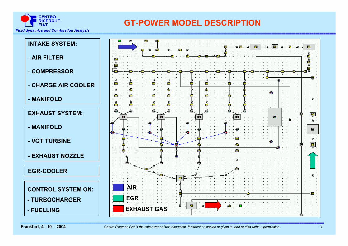
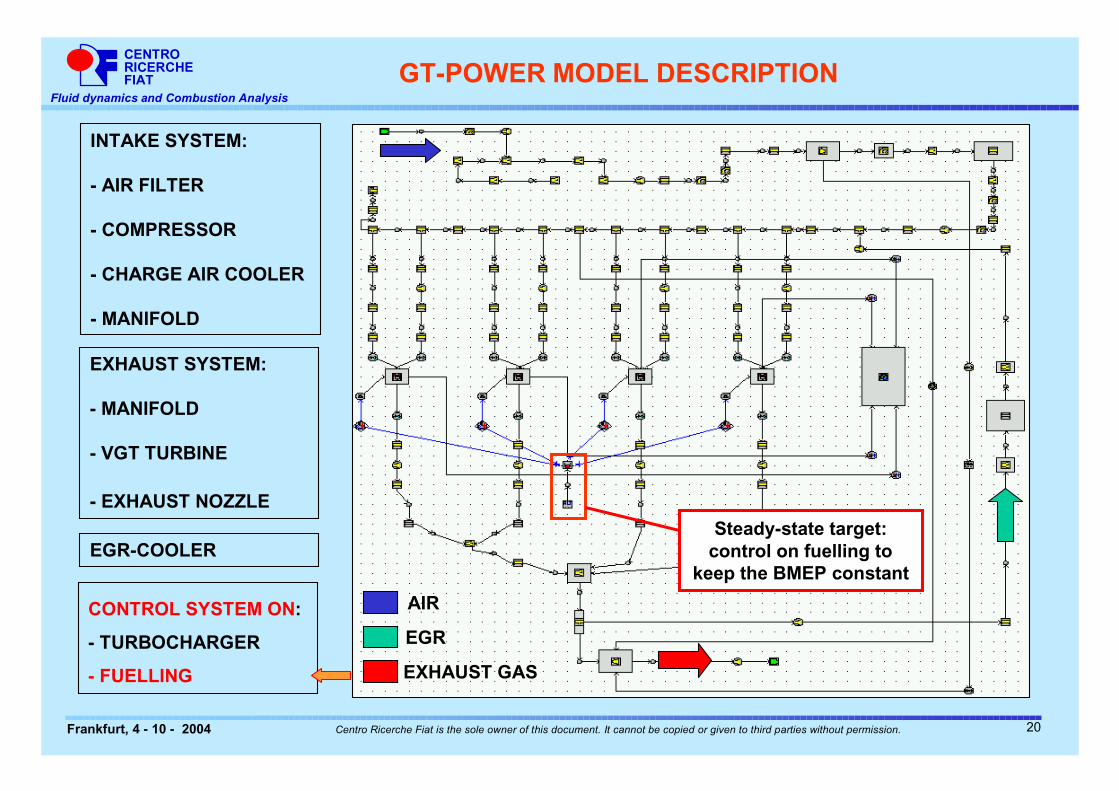
INTAKE SYSTEM:
- AIR FILTER
- COMPRESSOR
- CHARGE AIR COOLER
- MANIFOLD
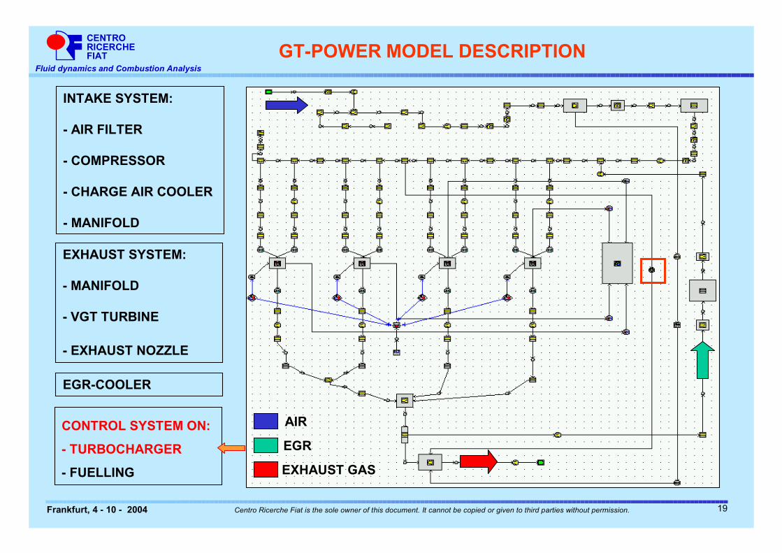
CONTROL SYSTEM ON:
- TURBOCHARGER
- FUELLING
EXHAUST SYSTEM:
- MANIFOLD
- VGT TURBINE
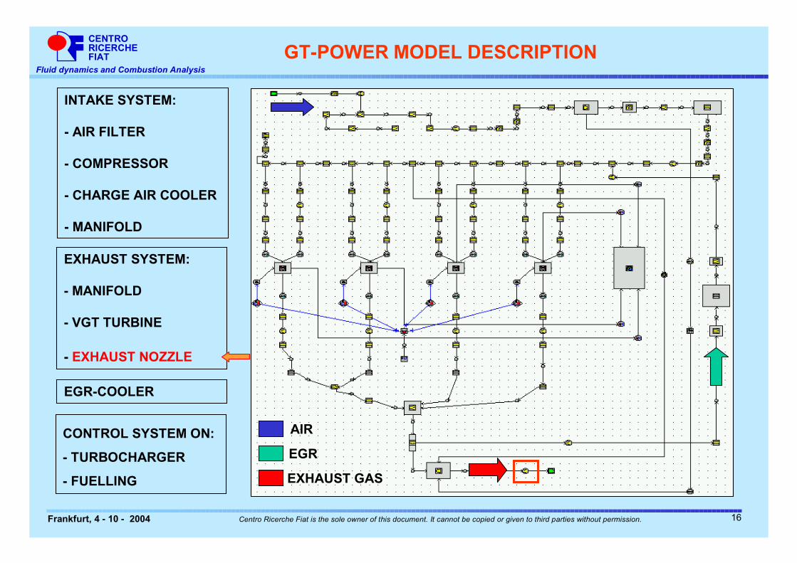
- EXHAUST NOZZLE
EGR
AIR
EXHAUST GAS
GT-POWER MODEL DESCRIPTION
EGR-COOLER
9
CENTRORICERCHEFIAT
Fluid dynamics and Combustion Analysis
Frankfurt, 4 - 10 - 2004 Centro Ricerche Fiat is the sole owner of this document. It cannot be copied or given to third parties without permission.
EGR
AIR
EXHAUST GAS
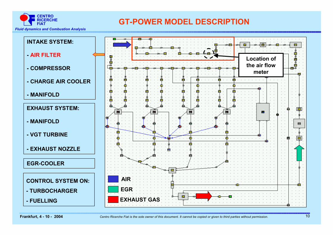
INTAKE SYSTEM:
- AIR FILTER
- COMPRESSOR
- CHARGE AIR COOLER
- MANIFOLD
CONTROL SYSTEM ON:
- TURBOCHARGER
- FUELLING
EXHAUST SYSTEM:
- MANIFOLD
- VGT TURBINE
- EXHAUST NOZZLE
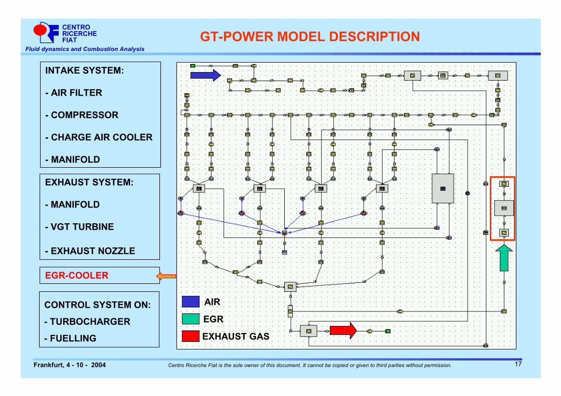
EGR-COOLER
GT-POWER MODEL DESCRIPTION
Location of the air flow
meter
10
CENTRORICERCHEFIAT
Fluid dynamics and Combustion Analysis
Frankfurt, 4 - 10 - 2004 Centro Ricerche Fiat is the sole owner of this document. It cannot be copied or given to third parties without permission.
EGR
AIR
EXHAUST GAS
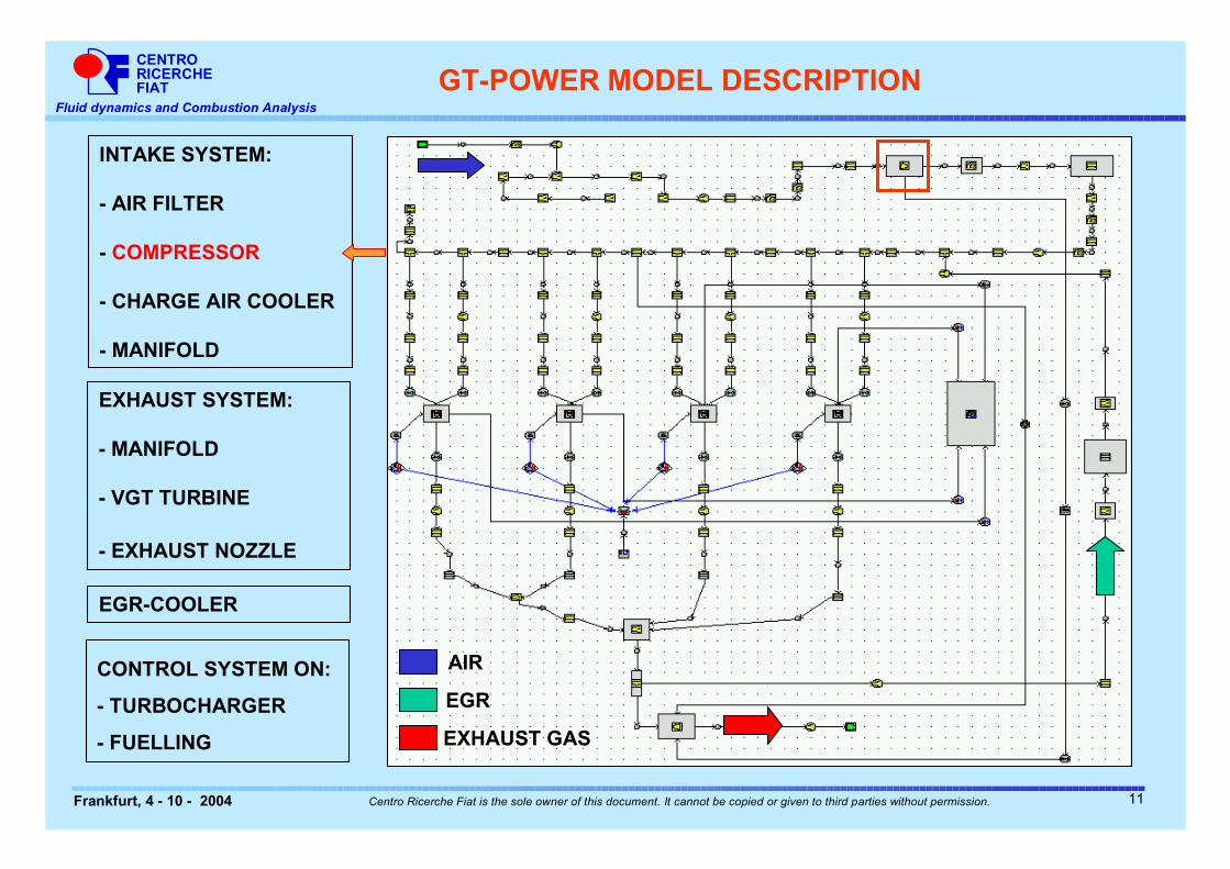
INTAKE SYSTEM:
- AIR FILTER
- COMPRESSOR
- CHARGE AIR COOLER
- MANIFOLD
CONTROL SYSTEM ON:
- TURBOCHARGER
- FUELLING
EXHAUST SYSTEM:
- MANIFOLD
- VGT TURBINE
- EXHAUST NOZZLE
EGR-COOLER
GT-POWER MODEL DESCRIPTION
11
CENTRORICERCHEFIAT
Fluid dynamics and Combustion Analysis
Frankfurt, 4 - 10 - 2004 Centro Ricerche Fiat is the sole owner of this document. It cannot be copied or given to third parties without permission.
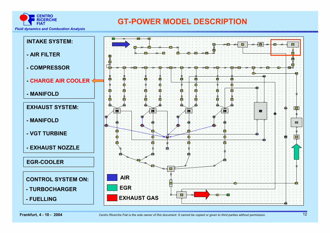
EGR
AIR
EXHAUST GAS
INTAKE SYSTEM:
- AIR FILTER
- COMPRESSOR
- CHARGE AIR COOLER
- MANIFOLD
CONTROL SYSTEM ON:
- TURBOCHARGER
- FUELLING
EXHAUST SYSTEM:
- MANIFOLD
- VGT TURBINE
- EXHAUST NOZZLE
EGR-COOLER
GT-POWER MODEL DESCRIPTION
12
CENTRORICERCHEFIAT
Fluid dynamics and Combustion Analysis
Frankfurt, 4 - 10 - 2004 Centro Ricerche Fiat is the sole owner of this document. It cannot be copied or given to third parties without permission.
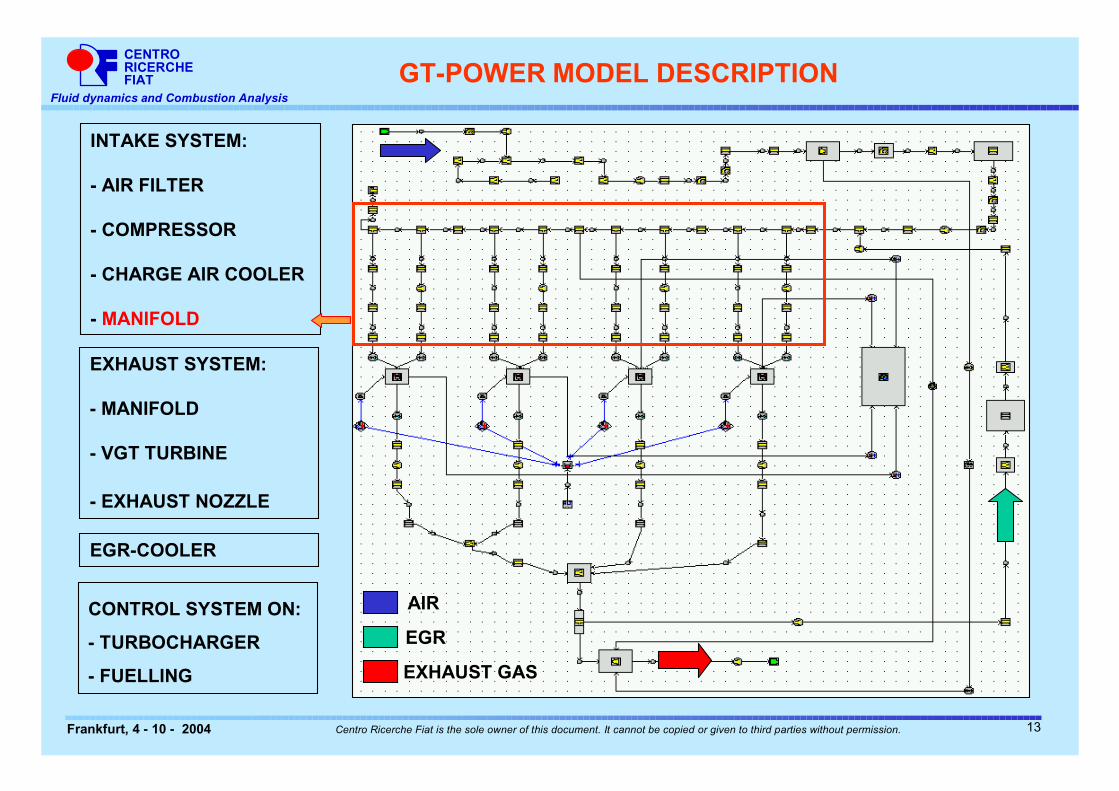
EGR
AIR
EXHAUST GAS
INTAKE SYSTEM:
- AIR FILTER
- COMPRESSOR
- CHARGE AIR COOLER
- MANIFOLD
CONTROL SYSTEM ON:
- TURBOCHARGER
- FUELLING
EXHAUST SYSTEM:
- MANIFOLD
- VGT TURBINE
- EXHAUST NOZZLE
EGR-COOLER
GT-POWER MODEL DESCRIPTION
13
CENTRORICERCHEFIAT
Fluid dynamics and Combustion Analysis
Frankfurt, 4 - 10 - 2004 Centro Ricerche Fiat is the sole owner of this document. It cannot be copied or given to third parties without permission.
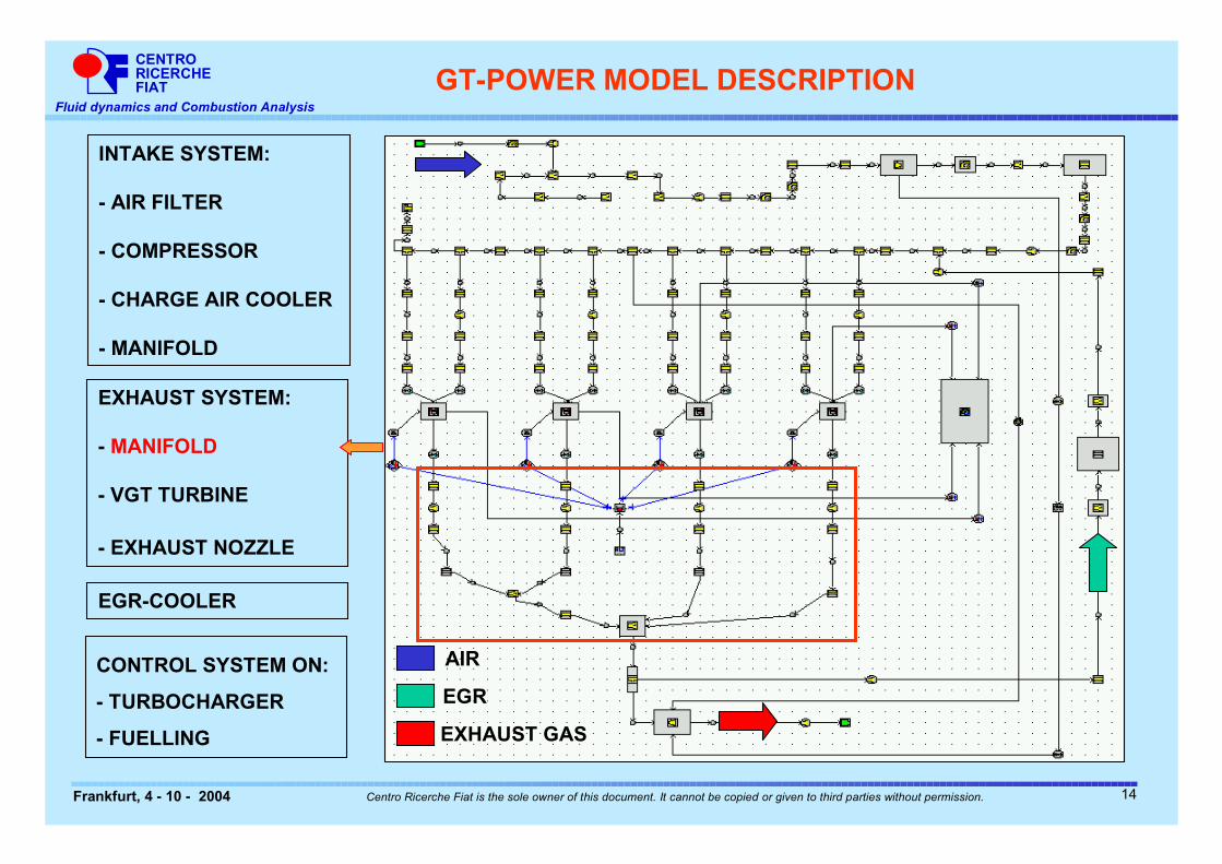
EGR
AIR
EXHAUST GAS
INTAKE SYSTEM:
- AIR FILTER
- COMPRESSOR
- CHARGE AIR COOLER
- MANIFOLD
CONTROL SYSTEM ON:
- TURBOCHARGER
- FUELLING
EXHAUST SYSTEM:
- MANIFOLD
- VGT TURBINE
- EXHAUST NOZZLE
EGR-COOLER
GT-POWER MODEL DESCRIPTION
14
CENTRORICERCHEFIAT
Fluid dynamics and Combustion Analysis
Frankfurt, 4 - 10 - 2004 Centro Ricerche Fiat is the sole owner of this document. It cannot be copied or given to third parties without permission.
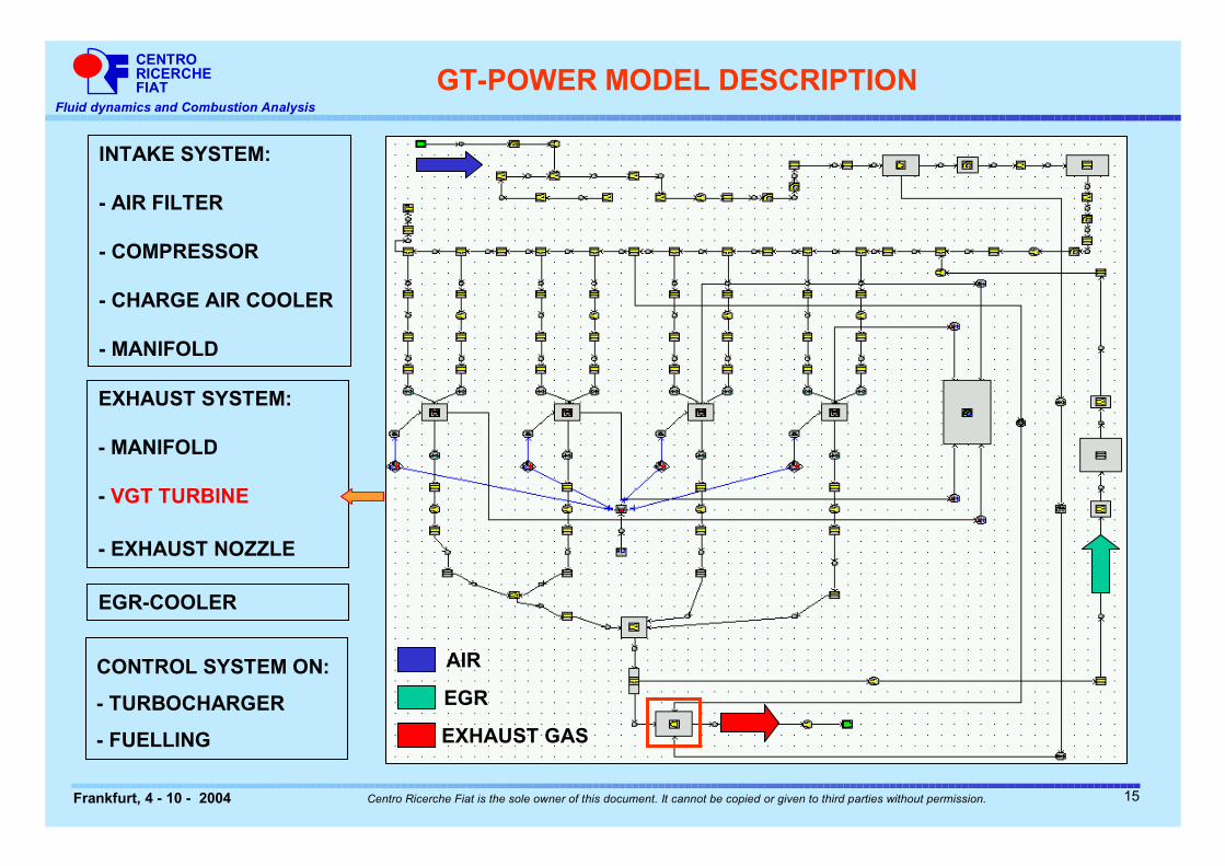
EGR
AIR
EXHAUST GAS
INTAKE SYSTEM:
- AIR FILTER
- COMPRESSOR
- CHARGE AIR COOLER
- MANIFOLD
CONTROL SYSTEM ON:
- TURBOCHARGER
- FUELLING
EXHAUST SYSTEM:
- MANIFOLD
- VGT TURBINE
- EXHAUST NOZZLE
EGR-COOLER
GT-POWER MODEL DESCRIPTION
15
CENTRORICERCHEFIAT
Fluid dynamics and Combustion Analysis
Frankfurt, 4 - 10 - 2004 Centro Ricerche Fiat is the sole owner of this document. It cannot be copied or given to third parties without permission.
EGR
AIR
EXHAUST GAS
INTAKE SYSTEM:
- AIR FILTER
- COMPRESSOR
- CHARGE AIR COOLER
- MANIFOLD
CONTROL SYSTEM ON:
- TURBOCHARGER
- FUELLING
EXHAUST SYSTEM:
- MANIFOLD
- VGT TURBINE
- EXHAUST NOZZLE
EGR-COOLER
GT-POWER MODEL DESCRIPTION
16
CENTRORICERCHEFIAT
Fluid dynamics and Combustion Analysis
Frankfurt, 4 - 10 - 2004 Centro Ricerche Fiat is the sole owner of this document. It cannot be copied or given to third parties without permission.
EGR
AIR
EXHAUST GAS
INTAKE SYSTEM:
- AIR FILTER
- COMPRESSOR
- CHARGE AIR COOLER
- MANIFOLD
CONTROL SYSTEM ON:
- TURBOCHARGER
- FUELLING
EXHAUST SYSTEM:
- MANIFOLD
- VGT TURBINE
- EXHAUST NOZZLE
EGR-COOLER
GT-POWER MODEL DESCRIPTION
17
CENTRORICERCHEFIAT
Fluid dynamics and Combustion Analysis
Frankfurt, 4 - 10 - 2004 Centro Ricerche Fiat is the sole owner of this document. It cannot be copied or given to third parties without permission.
AIR+EGR
AIR
EXHAUST GAS
INTAKE SYSTEM:
- AIR FILTER
- COMPRESSOR
- CHARGE AIR COOLER
- MANIFOLD
CONTROL SYSTEM ON:
- TURBOCHARGER
- FUELLING
EXHAUST SYSTEM:
- MANIFOLD
- VGT TURBINE
- EXHAUST NOZZLE
EGR-COOLER
GT-POWER MODEL DESCRIPTION
MAP
MAP XYZmap
GASmÿ
ε)(erpmmcoolantÿ
erpm
GASmÿ
ε
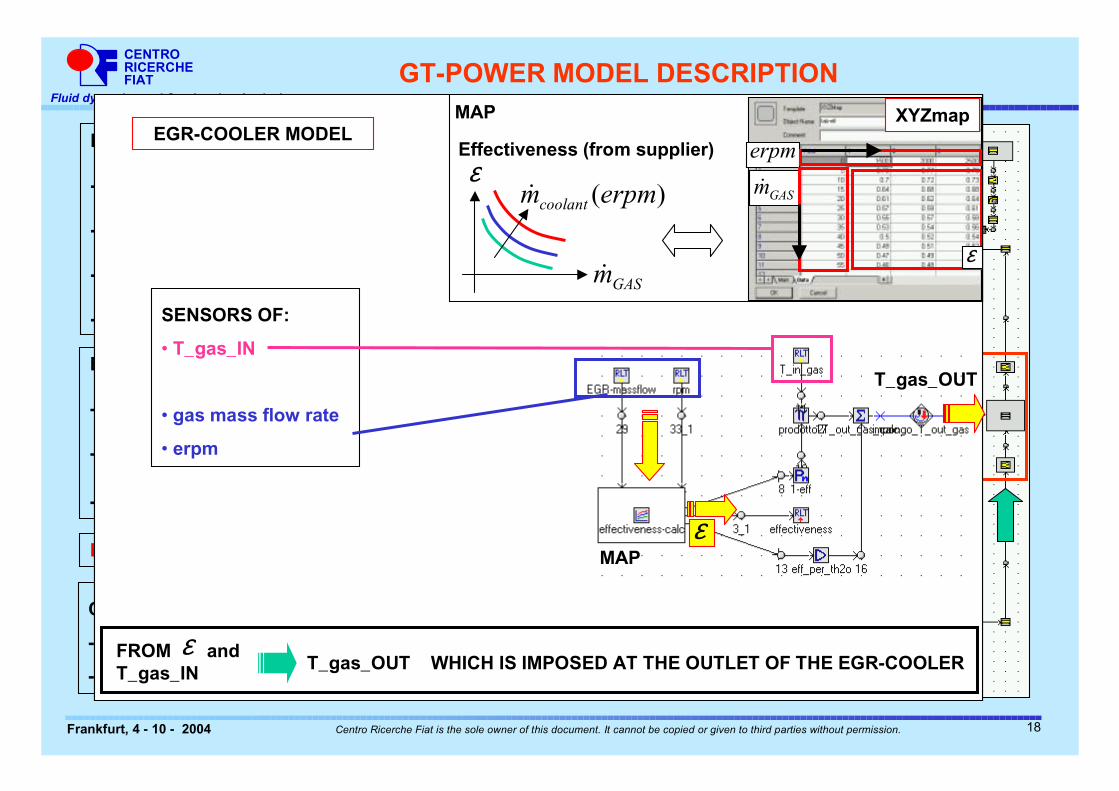
Effectiveness (from supplier)EGR-COOLER MODEL
SENSORS OF:
• T_gas_IN
• gas mass flow rate
• erpm
MAPε
XYZmap
GASmÿ
ε)(erpmmcoolantÿ
erpm
GASmÿ
ε
Effectiveness (from supplier)EGR-COOLER MODEL
SENSORS OF:
• T_gas_IN
• gas mass flow rate
• erpm
MAPε
MAP XYZmap
GASmÿ
ε)(erpmmcoolantÿ
erpm
GASmÿ
ε
Effectiveness (from supplier)EGR-COOLER MODEL
T_gas_OUT
FROM and T_gas_IN
εT_gas_OUT WHICH IS IMPOSED AT THE OUTLET OF THE EGR-COOLER
18
CENTRORICERCHEFIAT
Fluid dynamics and Combustion Analysis
Frankfurt, 4 - 10 - 2004 Centro Ricerche Fiat is the sole owner of this document. It cannot be copied or given to third parties without permission.
EGR
AIR
EXHAUST GAS
INTAKE SYSTEM:
- AIR FILTER
- COMPRESSOR
- CHARGE AIR COOLER
- MANIFOLD
CONTROL SYSTEM ON:
- TURBOCHARGER
- FUELLING
EXHAUST SYSTEM:
- MANIFOLD
- VGT TURBINE
- EXHAUST NOZZLE
EGR-COOLER
GT-POWER MODEL DESCRIPTION
19
CENTRORICERCHEFIAT
Fluid dynamics and Combustion Analysis
Frankfurt, 4 - 10 - 2004 Centro Ricerche Fiat is the sole owner of this document. It cannot be copied or given to third parties without permission.
EGR
AIR
EXHAUST GAS
INTAKE SYSTEM:
- AIR FILTER
- COMPRESSOR
- CHARGE AIR COOLER
- MANIFOLD
CONTROL SYSTEM ON:
- TURBOCHARGER
- FUELLING
EXHAUST SYSTEM:
- MANIFOLD
- VGT TURBINE
- EXHAUST NOZZLE
EGR-COOLER
GT-POWER MODEL DESCRIPTION
Steady-state target: control on fuelling to
keep the BMEP constant
20
CENTRORICERCHEFIAT
Fluid dynamics and Combustion Analysis
Frankfurt, 4 - 10 - 2004 Centro Ricerche Fiat is the sole owner of this document. It cannot be copied or given to third parties without permission.
PRESENTATION OVERVIEW
INTRODUCTION
GT-POWER MODEL DESCRIPTION
� TRANSIENT OF THE EGR PERCENTAGE AT CONSTANT ENGINE SPEED AND LOAD
� TRANSIENT OF EGR AND LOAD AT CONSTANT ENGINE SPEED
� REMARKS AND CONCLUSIONS
21
CENTRORICERCHEFIAT
Fluid dynamics and Combustion Analysis
Frankfurt, 4 - 10 - 2004 Centro Ricerche Fiat is the sole owner of this document. It cannot be copied or given to third parties without permission.
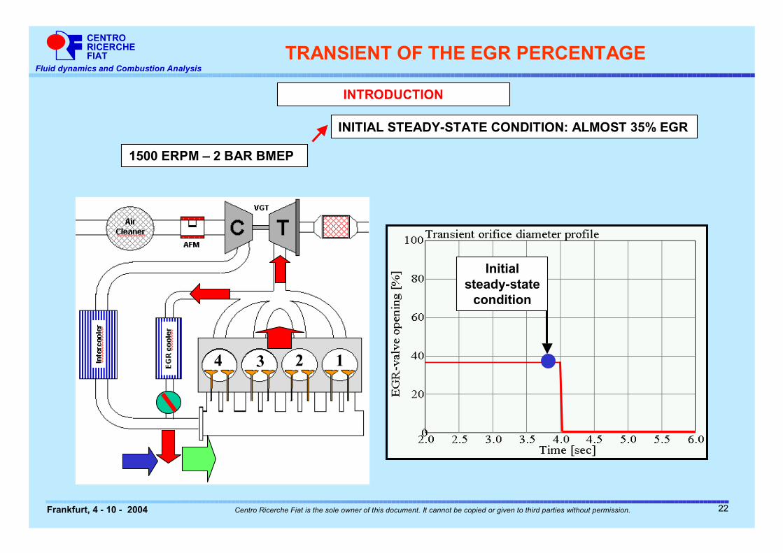
TRANSIENT OF THE EGR PERCENTAGE
4 3 2 1
1500 ERPM – 2 BAR BMEP
INITIAL STEADY-STATE CONDITION: ALMOST 35% EGR
Initial steady-state
condition
INTRODUCTION
22
CENTRORICERCHEFIAT
Fluid dynamics and Combustion Analysis
Frankfurt, 4 - 10 - 2004 Centro Ricerche Fiat is the sole owner of this document. It cannot be copied or given to third parties without permission.
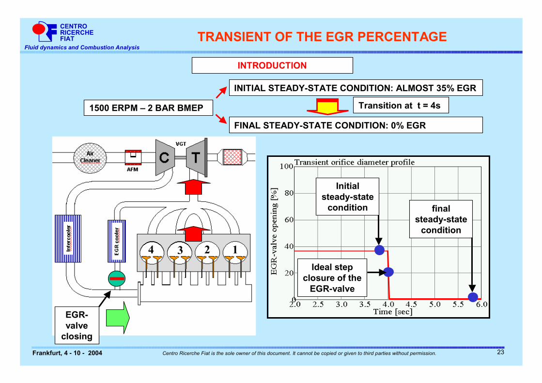
TRANSIENT OF THE EGR PERCENTAGE
4 3 2 1
1500 ERPM – 2 BAR BMEP
INITIAL STEADY-STATE CONDITION: ALMOST 35% EGR
FINAL STEADY-STATE CONDITION: 0% EGR
Initial steady-state
condition final steady-state
condition
Ideal step closure of the
EGR-valve
4 3 2 1
EGR-valve
closing
Transition at t = 4s
INTRODUCTION
23
CENTRORICERCHEFIAT
Fluid dynamics and Combustion Analysis
Frankfurt, 4 - 10 - 2004 Centro Ricerche Fiat is the sole owner of this document. It cannot be copied or given to third parties without permission.
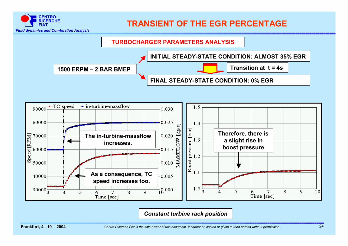
TRANSIENT OF THE EGR PERCENTAGE
TURBOCHARGER PARAMETERS ANALYSIS
Constant turbine rack position
1500 ERPM – 2 BAR BMEP
INITIAL STEADY-STATE CONDITION: ALMOST 35% EGR
FINAL STEADY-STATE CONDITION: 0% EGR
The in-turbine-massflow increases.
As a consequence, TC speed increases too.
Therefore, there is a slight rise in boost pressure
Transition at t = 4s
24
CENTRORICERCHEFIAT
Fluid dynamics and Combustion Analysis
Frankfurt, 4 - 10 - 2004 Centro Ricerche Fiat is the sole owner of this document. It cannot be copied or given to third parties without permission.
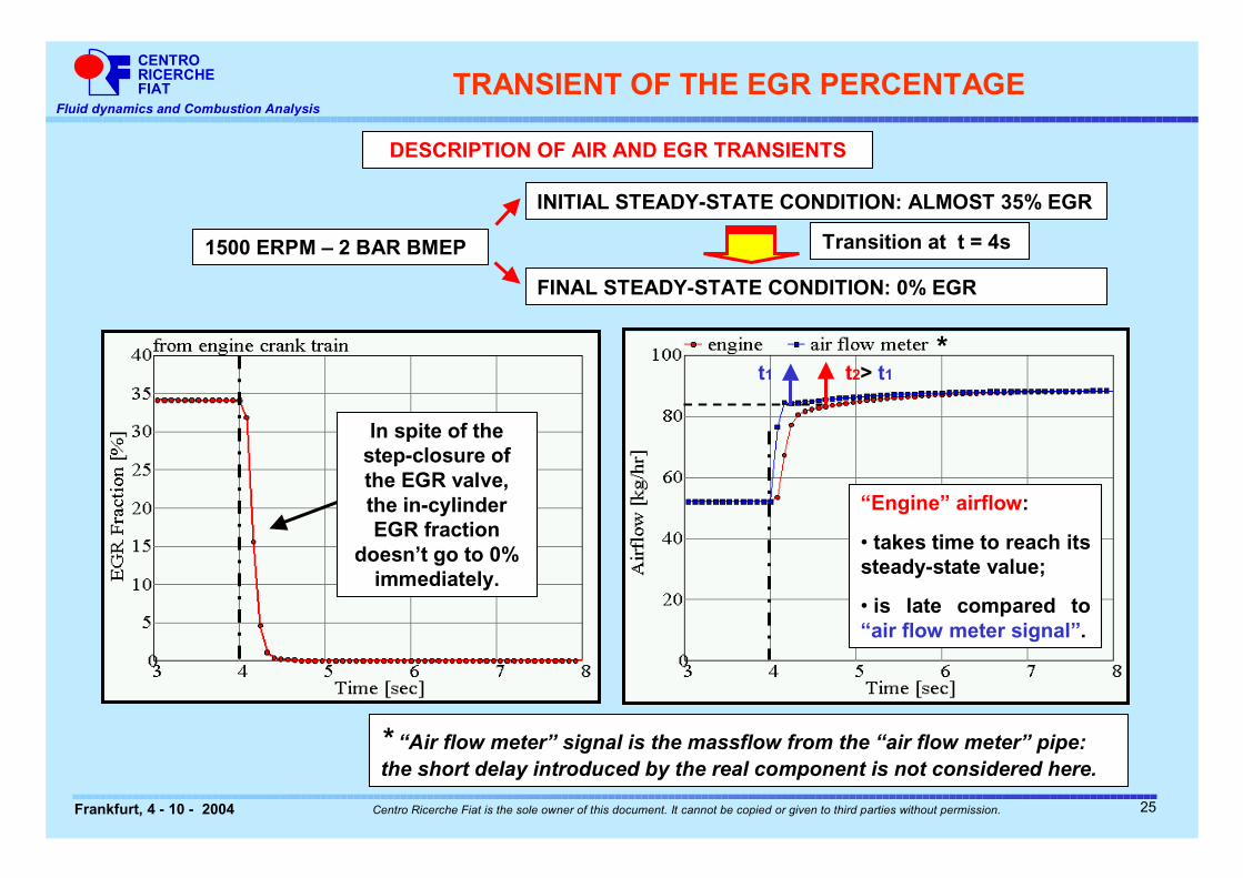
DESCRIPTION OF AIR AND EGR TRANSIENTS
1500 ERPM – 2 BAR BMEP
INITIAL STEADY-STATE CONDITION: ALMOST 35% EGR
FINAL STEADY-STATE CONDITION: 0% EGR
TRANSIENT OF THE EGR PERCENTAGE
In spite of the step-closure of the EGR valve, the in-cylinder EGR fraction
doesn’t go to 0% immediately.
“Engine” airflow:
• takes time to reach its steady-state value;
• is late compared to “air flow meter signal”.
* “Air flow meter” signal is the massflow from the “air flow meter” pipe: the short delay introduced by the real component is not considered here.
*t1 t2> t1
Transition at t = 4s
25
CENTRORICERCHEFIAT
Fluid dynamics and Combustion Analysis
Frankfurt, 4 - 10 - 2004 Centro Ricerche Fiat is the sole owner of this document. It cannot be copied or given to third parties without permission.
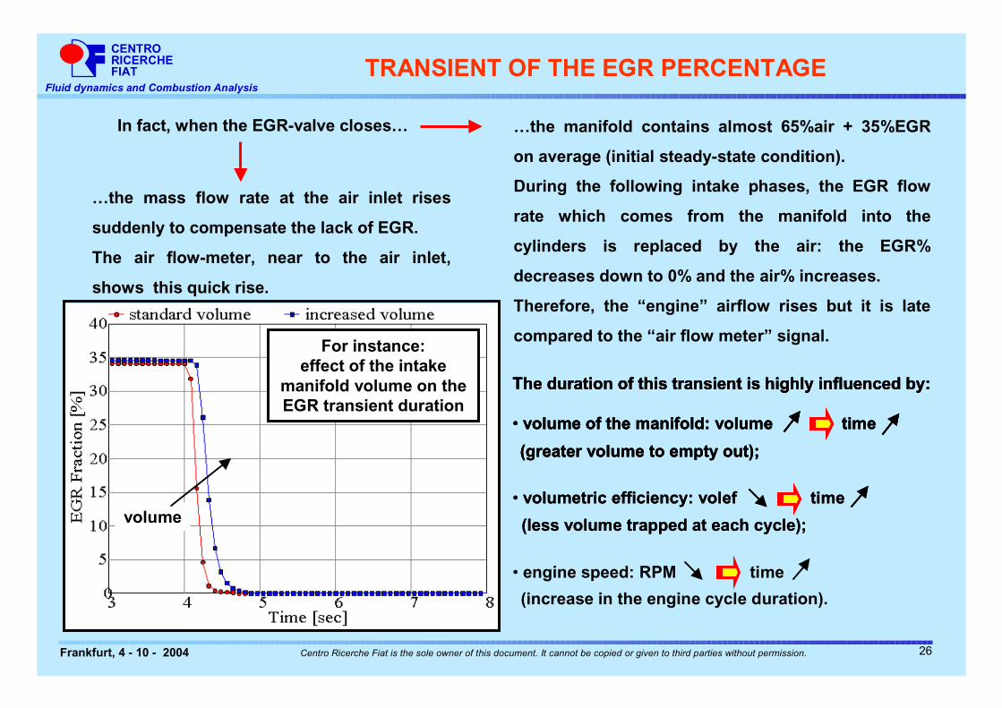
TRANSIENT OF THE EGR PERCENTAGE
…the mass flow rate at the air inlet rises
suddenly to compensate the lack of EGR.
The air flow-meter, near to the air inlet,
shows this quick rise.
In fact, when the EGR-valve closes… …the manifold contains almost 65%air + 35%EGR
on average (initial steady-state condition).
During the following intake phases, the EGR flow
rate which comes from the manifold into the
cylinders is replaced by the air: the EGR%
decreases down to 0% and the air% increases.
Therefore, the “engine” airflow rises but it is late
compared to the “air flow meter” signal.
volume
For instance: effect of the intake
manifold volume on the EGR transient duration
The duration of this transient is highly influenced by:
• volume of the manifold: volume time
(greater volume to empty out);
The duration of this transient is highly influenced by:
• volume of the manifold: volume time
• volumetric efficiency: volef time
(greater volume to empty out);
(less volume trapped at each cycle);
The duration of this transient is highly influenced by:
• volume of the manifold: volume time
• volumetric efficiency: volef time
• engine speed: RPM time
(increase in the engine cycle duration).
(greater volume to empty out);
(less volume trapped at each cycle);
26
CENTRORICERCHEFIAT
Fluid dynamics and Combustion Analysis
Frankfurt, 4 - 10 - 2004 Centro Ricerche Fiat is the sole owner of this document. It cannot be copied or given to third parties without permission.
PRESENTATION OVERVIEW
INTRODUCTION
GT-POWER MODEL DESCRIPTION
TRANSIENT OF THE EGR PERCENTAGE AT CONSTANT ENGINE SPEED AND LOAD
� TRANSIENT OF EGR AND LOAD AT CONSTANT ENGINE SPEED
� REMARKS AND CONCLUSIONS
27
CENTRORICERCHEFIAT
Fluid dynamics and Combustion Analysis
Frankfurt, 4 - 10 - 2004 Centro Ricerche Fiat is the sole owner of this document. It cannot be copied or given to third parties without permission.
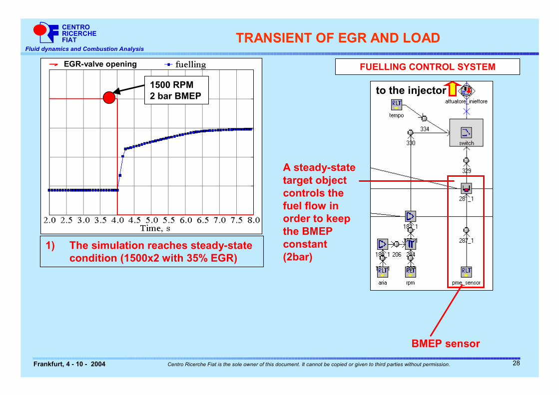
1) The simulation reaches steady-state condition (1500x2 with 35% EGR)
BMEP sensor
A steady-state target object controls the fuel flow in order to keep the BMEP constant (2bar)
to the injector
TRANSIENT OF EGR AND LOAD
EGR-valve opening FUELLING CONTROL SYSTEM
1500 RPM 2 bar BMEP
28
CENTRORICERCHEFIAT
Fluid dynamics and Combustion Analysis
Frankfurt, 4 - 10 - 2004 Centro Ricerche Fiat is the sole owner of this document. It cannot be copied or given to third parties without permission.
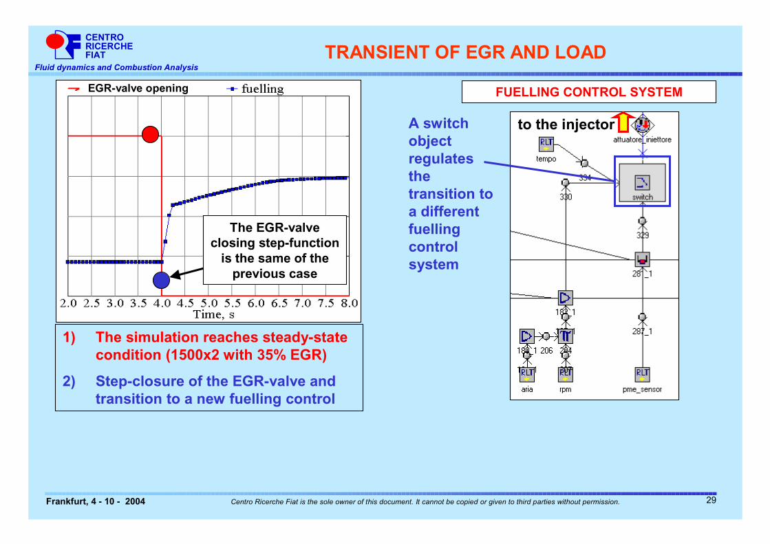
1) The simulation reaches steady-state condition (1500x2 with 35% EGR)
2) Step-closure of the EGR-valve and transition to a new fuelling control
A switch object regulates the transition to a different fuelling control system
EGR-valve opening
to the injector
FUELLING CONTROL SYSTEM
The EGR-valve closing step-function
is the same of the previous case
TRANSIENT OF EGR AND LOAD
29
CENTRORICERCHEFIAT
Fluid dynamics and Combustion Analysis
Frankfurt, 4 - 10 - 2004 Centro Ricerche Fiat is the sole owner of this document. It cannot be copied or given to third parties without permission.
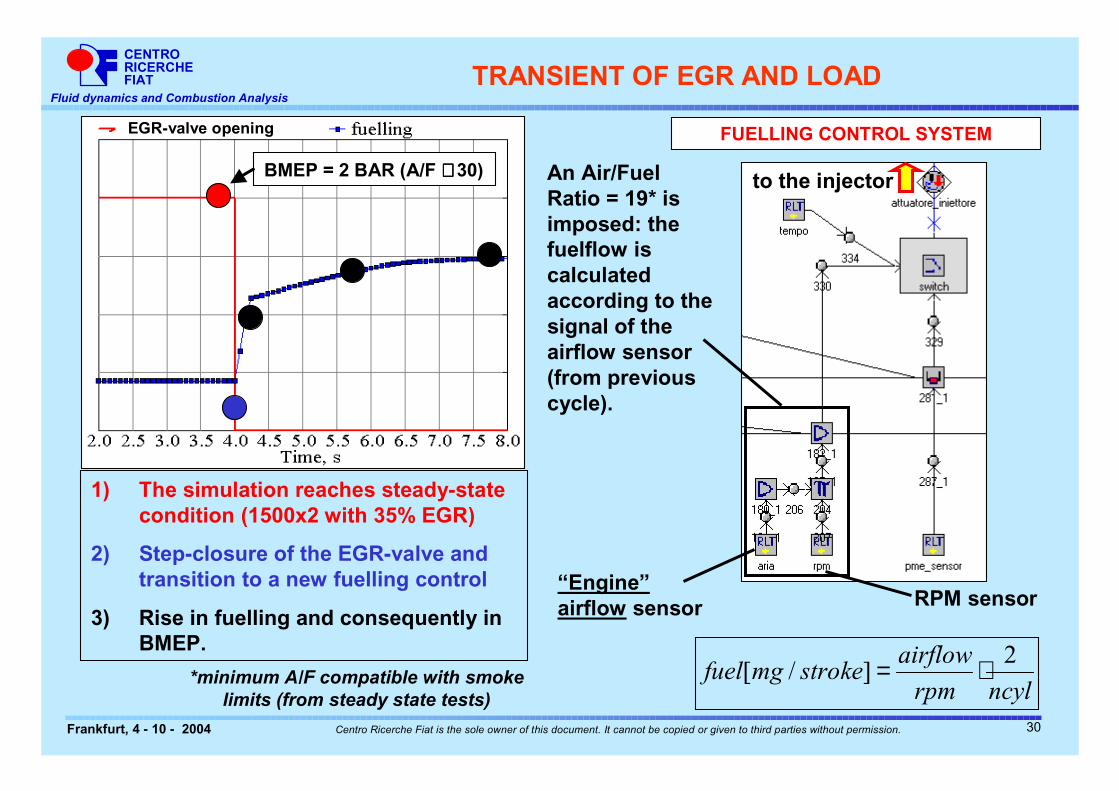
1) The simulation reaches steady-state condition (1500x2 with 35% EGR)
2) Step-closure of the EGR-valve and transition to a new fuelling control
3) Rise in fuelling and consequently in BMEP.
“Engine” airflow sensor
An Air/Fuel Ratio = 19* is imposed: the fuelflow is calculated according to the signal of the airflow sensor (from previous cycle).
EGR-valve opening
to the injector
RPM sensor
FUELLING CONTROL SYSTEM
ncylrpm
airflowstrokemgfuel
2]/[ ⋅=
BMEP = 2 BAR (A/F ≅≅≅≅ 30)
*minimum A/F compatible with smoke limits (from steady state tests)
TRANSIENT OF EGR AND LOAD
30
CENTRORICERCHEFIAT
Fluid dynamics and Combustion Analysis
Frankfurt, 4 - 10 - 2004 Centro Ricerche Fiat is the sole owner of this document. It cannot be copied or given to third parties without permission.
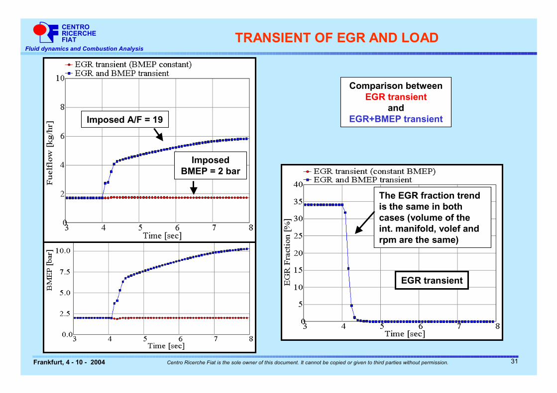
Imposed A/F = 19
Imposed BMEP = 2 bar
Comparison between EGR transient
and EGR+BMEP transient
The EGR fraction trend is the same in both cases (volume of the int. manifold, volef and rpm are the same)
EGR transient
TRANSIENT OF EGR AND LOAD
31
CENTRORICERCHEFIAT
Fluid dynamics and Combustion Analysis
Frankfurt, 4 - 10 - 2004 Centro Ricerche Fiat is the sole owner of this document. It cannot be copied or given to third parties without permission.
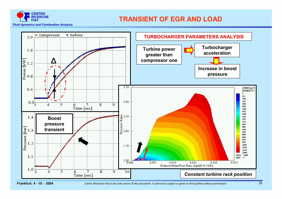
TURBOCHARGER PARAMETERS ANALYSIS
∆∆∆∆Turbine power
greater than compressor one
Turbocharger acceleration
Increase in boost pressure
Boost pressure transient
Constant turbine rack position
TRANSIENT OF EGR AND LOAD
32
CENTRORICERCHEFIAT
Fluid dynamics and Combustion Analysis
Frankfurt, 4 - 10 - 2004 Centro Ricerche Fiat is the sole owner of this document. It cannot be copied or given to third parties without permission.
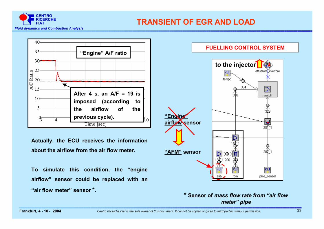
to the injector
FUELLING CONTROL SYSTEM
“Engine” airflow sensor
“AFM” sensor
After 4 s, an A/F = 19 is imposed (according to the airflow of the previous cycle).
“Engine” A/F ratio
Actually, the ECU receives the information
about the airflow from the air flow meter.
To simulate this condition, the “engine
airflow” sensor could be replaced with an
“air flow meter” sensor *.* Sensor of mass flow rate from “air flow
meter” pipe
TRANSIENT OF EGR AND LOAD
33
CENTRORICERCHEFIAT
Fluid dynamics and Combustion Analysis
Frankfurt, 4 - 10 - 2004 Centro Ricerche Fiat is the sole owner of this document. It cannot be copied or given to third parties without permission.
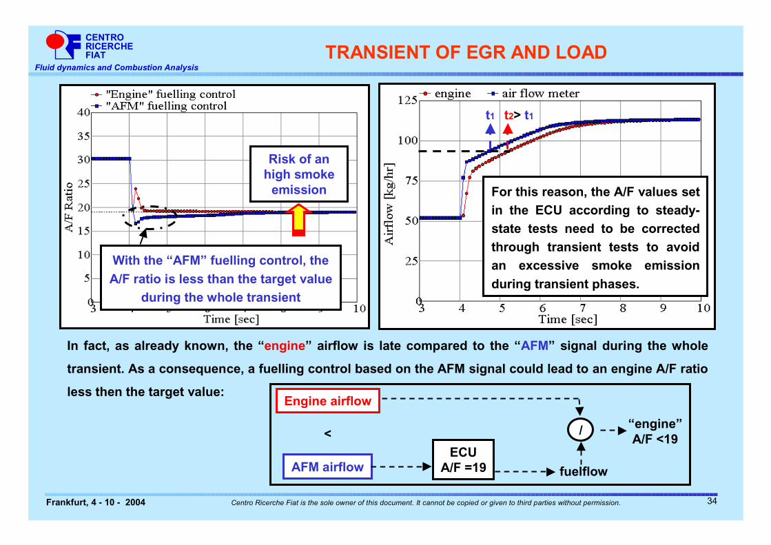
In fact, as already known, the “engine” airflow is late compared to the “AFM” signal during the whole
transient. As a consequence, a fuelling control based on the AFM signal could lead to an engine A/F ratio
less then the target value:
With the “AFM” fuelling control, the A/F ratio is less than the target value
during the whole transient
Risk of an high smoke
emission For this reason, the A/F values set in the ECU according to steady-state tests need to be corrected through transient tests to avoid an excessive smoke emission during transient phases.
t1 t2> t1
TRANSIENT OF EGR AND LOAD
AFM airflow
Engine airflow
ECUA/F =19
<
fuelflow
/ “engine”A/F <19
34
CENTRORICERCHEFIAT
Fluid dynamics and Combustion Analysis
Frankfurt, 4 - 10 - 2004 Centro Ricerche Fiat is the sole owner of this document. It cannot be copied or given to third parties without permission.
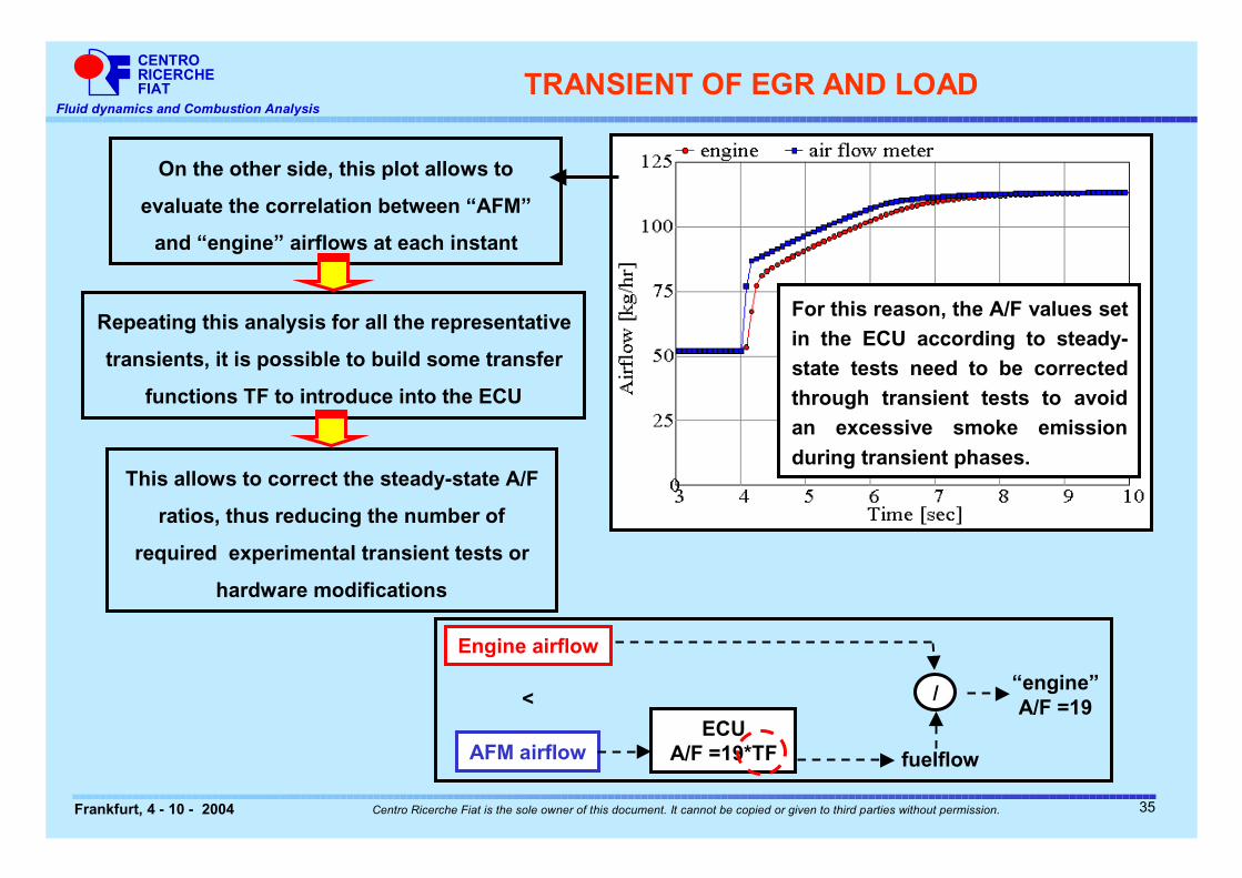
On the other side, this plot allows to
evaluate the correlation between “AFM”
and “engine” airflows at each instant
Repeating this analysis for all the representative
transients, it is possible to build some transfer
functions TF to introduce into the ECU
This allows to correct the steady-state A/F
ratios, thus reducing the number of
required experimental transient tests or
hardware modifications
For this reason, the A/F values set in the ECU according to steady-state tests need to be corrected through transient tests to avoid an excessive smoke emission during transient phases.
TRANSIENT OF EGR AND LOAD
AFM airflow
Engine airflow
ECUA/F =19*TF
<
fuelflow
/ “engine”A/F =19
35

CENTRORICERCHEFIAT
Fluid dynamics and Combustion Analysis
Frankfurt, 4 - 10 - 2004 Centro Ricerche Fiat is the sole owner of this document. It cannot be copied or given to third parties without permission.
PRESENTATION OVERVIEW
INTRODUCTION
GT-POWER MODEL DESCRIPTION
TRANSIENT OF THE EGR PERCENTAGE AT CONSTANT ENGINE SPEED AND LOAD
TRANSIENT OF EGR AND LOAD AT CONSTANT ENGINE SPEED
� REMARKS AND CONCLUSIONS
36
CENTRORICERCHEFIAT
Fluid dynamics and Combustion Analysis
Frankfurt, 4 - 10 - 2004 Centro Ricerche Fiat is the sole owner of this document. It cannot be copied or given to third parties without permission.
REMARKS AND CONCLUSIONS
THE USE OF GT-POWER CODE ALLOWS TO UNDERSTAND THE FLUID-DYNAMICS AND
TURBOCHARGER PHENOMENA INVOLVED IN A TRANSIENT.
IN PARTICULAR, THE PRESENT ANALYSIS SHOWS THAT:
• DURING A SUDDEN ACCELERATION FROM A PART LOAD POINT AN EGR TRANSIENT AND A
BOOST PRESSURE TRANSIENT PHASES COULD BE RECOGNIZED. THE CODE ALLOWS TO
IDENTIFY THE RELEVANT PARAMETERS (E.G. THE VOLUME OF THE INTAKE MANIFOLD…)
• DURING TRANSIENT PHASES THE OUTPUT OF THE AIR FLOW METER COULD BE NOT
REPRESENTATIVE OF THE TOTAL IN-CYLINDER TRAPPED AIRFLOW. THIS COULD RISES
PROBLEMS (E.G. NOT CONTROLLED SMOKE EMISSION) WHEN FUELLING IS CALCULATED IN OPEN
LOOP BY THE ECU ACCORDING TO THAT SIGNAL;
• BY THE USE OF GT-POWER IT IS POSSIBLE TO IDENTIFY THE CORRELATION BETWEEN THE
SIGNAL OF THE AIR FLOW METER AND THE TOTAL IN-CYLINDER TRAPPED AIRFLOW DURING
TRANSIENT PHASES. THIS COULD ALLOW AN EASIER CONTROL OF THE ENGINE A/F RATIO
REDUCING THE NEED OF EXPENSIVE TRANSIENT TESTS.
37