Embed Size (px)
Citation preview

EG1108PART 2 EXERCISES ~PAGE 1EG1108PART 2 EXERCISES ~PAGE 1 BEN M.CHEN,NUSECEBEN M.CHEN,NUSECE
EG1108Tutorial5:Transformers&RectifierCircuits– Part1EG1108Tutorial5:Transformers&RectifierCircuits– Part1
1. Itisshowninthelecturethatanidealmutualinductorhasthefollowingproperties:
ShowintheACenvironment,thepropertiescanberepresentinfollowingphasor form:

EG1108PART 2 EXERCISES ~PAGE 2EG1108PART 2 EXERCISES ~PAGE 2 BEN M.CHEN,NUSECEBEN M.CHEN,NUSECE
2. Anidealtransformerhasaturnsratioof3:2.Itisdesiredtooperatea200 resistiveloadat150V.Findtheprimaryandsecondarycurrents,thesourcevoltage,thepowerdeliveredtotheprimaryfromthesource,andtheimpedancethesourceseeslookingintotheprimarywinding.
Answers:0.5 A,0.75 A,225 V,112.5 W,450
3. Atransformeristobeusedtomatchan8 loudspeakertoa500 audioline.Theaudiopowerdeliveredtothespeakeris10W.Find:
i. turnsratioofthetransformer,
ii. thevoltagesatprimaryandsecondaryterminalsofthetransformer.
Assumethatthespeakerisresistiveandthatthetransformerisideal.
Answers:turnsratio=7.9:1;V2=8.94V,V1=70.6V
4. Thehighvoltagesideofastep‐downtransformerhas800turns,andthelowvoltagesidehas100turns.Avoltageof2400 Visappliedtothehighvoltagesideanda3+j4Ωloadisconnectedonthelowvoltageside.Find:
i. Thesecondaryvoltageandcurrent.
ii. Theprimarycurrent.
iii. Thereflectedimpedanceseenfromtheprimaryside.
Answers:300 V, 6 53.13 A; 0.75 53.13 A; 320 53.13 Ω
EG1108Tutorial5(cont.)EG1108Tutorial5(cont.)

EG1108PART 2 EXERCISES ~PAGE 3EG1108PART 2 EXERCISES ~PAGE 3 BEN M.CHEN,NUSECEBEN M.CHEN,NUSECE
5. Considerthetransformercircuitasshownbelow.Theinputtothecircuitisthevoltageofthevoltagesource,vs(t).Determinetheoutputvoltage,vo(t)acrossthe6Hinductor.Thetransformationratiois2:5.
Answer:
s ( )8.92cos(2 74 ) Vv t
t
o ( ) 4.684cos(2 151.85 ) Vv t t
EG1108Tutorial5(cont.)EG1108Tutorial5(cont.)
EG1108PART 2 EXERCISES ~PAGE 4EG1108PART 2 EXERCISES ~PAGE 4 BEN M.CHEN,NUSECEBEN M.CHEN,NUSECE
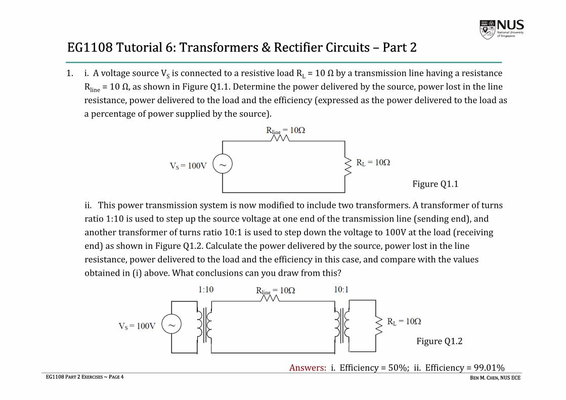
1. i.AvoltagesourceVS isconnectedtoaresistiveloadRL =10ΩbyatransmissionlinehavingaresistanceRline =10Ω,asshowninFigureQ1.1.Determinethepowerdeliveredbythesource,powerlostinthelineresistance,powerdeliveredtotheloadandtheefficiency(expressedasthepowerdeliveredtotheloadasapercentageofpowersuppliedbythesource).
ii.Thispowertransmissionsystemisnowmodifiedtoincludetwotransformers.Atransformerofturnsratio1:10isusedtostepupthesourcevoltageatoneendofthetransmissionline(sendingend),andanothertransformerofturnsratio10:1isusedtostepdownthevoltageto100Vattheload(receivingend)asshowninFigureQ1.2.Calculatethepowerdeliveredbythesource,powerlostinthelineresistance,powerdeliveredtotheloadandtheefficiencyinthiscase,andcomparewiththevaluesobtainedin(i)above.Whatconclusionscanyoudrawfromthis?
Answers:i.Efficiency=50%;ii.Efficiency=99.01%
FigureQ1.1
FigureQ1.2
EG1108Tutorial6:Transformers&RectifierCircuits– Part2EG1108Tutorial6:Transformers&RectifierCircuits– Part2

EG1108PART 2 EXERCISES ~PAGE 5EG1108PART 2 EXERCISES ~PAGE 5 BEN M.CHEN,NUSECEBEN M.CHEN,NUSECE
3. Afullwavebridgerectifier,withalargesmoothingcapacitorissupplyingpowertoa10Ωloadresistance.Thesecondaryvoltageofthetransformersupplyingpowertherectifieris8V(rms)at50Hz.Assumingthatthediodesareideal,whatistheapproximatevalueoffiltercapacitorrequiredsuchthatthepeak‐to‐peakrippleis5%orless?
Answer:0.02F
2. ADCpowersupplyconsistsofatransformerfeedingahalf‐waverectifiertogetherwithacapacitorfilter.ItsuppliesaDCcurrentof1Aat12VDCtoanelectronicequipment.TheACinputsourceis230V(rms)at50Hz.Theoutputsidefiltercapacitorusedis50000μF.
i. Drawthecircuitdiagramofthesupplyarrangement.
ii. Determineasuitablewindingratioforthetransformer.Treattheoperationofthepowersupplyasideal(i.e.,neglectvoltagedropinthediodeandassumethatthetransformerisideal).
iii. Whatisthepeak‐to‐peakrippleintheoutputvoltage?Whatistheripplefrequency?Whatisthepercentageripple?
iv. Sketchthefollowingwaveforms:ACinputvoltage,secondaryACvoltage,rectifieroutputvoltage.Marktheintervalwhenthediodeconducts.
Answers:(ii)27:1;(iii)%ripple=3.33%
EG1108Tutorial6(cont.)EG1108Tutorial6(cont.)

EG1108PART 2 EXERCISES ~PAGE 6EG1108PART 2 EXERCISES ~PAGE 6 BEN M.CHEN,NUSECEBEN M.CHEN,NUSECE
4. TherectifiersupplyshowninFigureQ4isusedaspartofanelectroniccircuit.Theinputvoltageissinusoidalwithapeakamplitudeof50V,and10kHzfrequency.Thetransformerprimarytosecondaryratio=1:3.Theloadresistanceis10kΩ. Neglectdiodeconductionvoltagedrops.Also,assumeidealoperationofthetransformerneglectingleakage,lossesetc.
i. DeterminetheoutputDCvoltage.Whatisthepeak‐to‐peakrippleintheoutputvoltage?Whatisthepercentageripple?
ii. Sketchwaveformsforv1 ,v2,v3 ,vYX,vo,io ,i2,i3,vD2.Markthediodeconductionintervals.
iii. Whatisthemaximumreversevoltageappliedacrossthediodes?Whendotheyoccur?
Answers: i.47.8V;75V;157%;iii.150V
FigureQ4
EG1108Tutorial6(cont.)EG1108Tutorial6(cont.)

EG1108PART 2 EXERCISES ~PAGE 7EG1108PART 2 EXERCISES ~PAGE 7 BEN M.CHEN,NUSECEBEN M.CHEN,NUSECE
5. Forthehalf‐waveandfull‐waverectifiercircuitswithcapacitorfilteringthatwehavestudied,commentwhethertheresultingoutputvoltagewillbesmoothDCiftheinputvoltageisgivenasfollows.
Giveyourjustification.
Answers: Yesifthecapacitanceissufficientlylarge
EG1108Tutorial6(cont.)EG1108Tutorial6(cont.)
2Vm
Vm
EG1108PART 2 EXERCISES ~PAGE 8EG1108PART 2 EXERCISES ~PAGE 8 BEN M.CHEN,NUSECEBEN M.CHEN,NUSECE
EG1108Tutorial7:DigitalLogicCircuits– Part1EG1108Tutorial7:DigitalLogicCircuits– Part1
1. SimplifythefollowingBooleanexpressionsusingrulesofBooleanAlgebraandDeMorgan’stheorems:
i. Answer:
ii. Answer:
iii. Answer:
iv. Answer:
v. Answer:
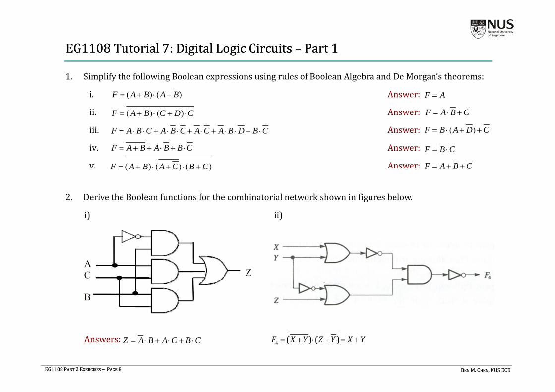
2. DerivetheBooleanfunctionsforthecombinatorialnetworkshowninfiguresbelow.
i) ii)
Answers:
( ) ( )F A B A B
( ) ( )F A B C D C F A B C
F A
F A B C A B C A C A B D B C ( )F B A D C
F A B A B B C F B C
( ) ( ) ( )F A B A C B C F A B C
Z A B A C B C 4 ( ) ( )F X Y Z Y X Y

EG1108PART 2 EXERCISES ~PAGE 9EG1108PART 2 EXERCISES ~PAGE 9 BEN M.CHEN,NUSECEBEN M.CHEN,NUSECE
3. UseonlyNORgateswith2inputstofindawaytoimplementtheexclusiveORfunction .
EG1108Tutorial7(cont.)EG1108Tutorial7(cont.)
Z A B
5. Thelogiccircuitbelowisknownasaparitycheckerfora4‐bitbinarynumber.
i. Constructatruthtableforthecircuit.
ii. VerifythatFistrueifandonlyifthenumberoftheinputsthatarehighiseither1or3.
4. UseonlyNANDgateswith2inputstofindawaytoimplementtheexclusiveNORfunction . Z A B
EG1108PART 2 EXERCISES ~PAGE 10EG1108PART 2 EXERCISES ~PAGE 10 BEN M.CHEN,NUSECEBEN M.CHEN,NUSECE
EG1108Tutorial8:DigitalLogicCircuits– Part2EG1108Tutorial8:DigitalLogicCircuits– Part2
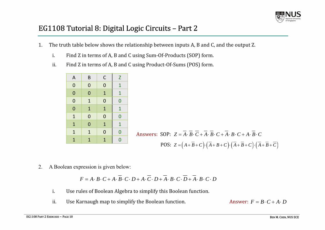
1. ThetruthtablebelowshowstherelationshipbetweeninputsA,BandC,andtheoutputZ.
i. FindZintermsofA,BandCusingSum‐Of‐Products(SOP)form.
ii. FindZintermsofA,BandCusingProduct‐Of‐Sums(POS)form.
Answers: SOP:
POS:
A B C Z0 0 0 10 0 1 10 1 0 00 1 1 11 0 0 01 0 1 11 1 0 01 1 1 0
Z A B C A B C A B C A B C
Z A B C A B C A B C A B C
2. A Boolean expression is given below:
i. UserulesofBooleanAlgebratosimplifythisBooleanfunction.
ii. UseKarnaugh maptosimplifytheBooleanfunction. Answer:
F A B C A B C D A C D A B C D A B C D
F B C A D

EG1108PART 2 EXERCISES ~PAGE 11EG1108PART 2 EXERCISES ~PAGE 11 BEN M.CHEN,NUSECEBEN M.CHEN,NUSECE
4. Fromthetableshownbelow,findZintermsofA,BandCusingProduct‐Of‐Sums(POS)form.UseKarnaugh maptosimplifytheresultingexpression.
Answer:
A B C Z0 0 0 10 0 1 00 1 0 00 1 1 11 0 0 01 0 1 11 1 0 01 1 1 0
( ) ( ) ( ) ( )Z A B B C A C A B C
3. UseKarnaugh maptosimplifythefollowingBooleanfunction:
Answer:F A B C A B C A C A B D B C F C A B B D
EG1108Tutorial8 (cont.)EG1108Tutorial8 (cont.)

EG1108PART 2 EXERCISES ~PAGE 12EG1108PART 2 EXERCISES ~PAGE 12 BEN M.CHEN,NUSECEBEN M.CHEN,NUSECE
EG1108Tutorial8 (cont.)EG1108Tutorial8 (cont.)
5. Designalogiccircuittocontrolelectricalpowertotheengineignitionofaspeedboat.
LogicoutputIistobecomehighifignitionpoweristobeappliedandremainlow otherwise.Gasolinefumesintheenginecompartmentpresentaserioushazardofexplosion.AsensorprovidesalogicinputFthatishighiffumesarepresent.Ignitionpower shouldnotbeappliediffumesarepresent.Tohelppreventaccidents,ignitionpowershouldnotbeappliedwhiletheoutdriveisingear.LogicsignalGishighiftheoutdriveisingearandislowotherwise.
Ablowerisprovidedtoclearfumesfromtheenginecompartmentandistobeoperatedforfiveminutesbeforeapplyingignitionpower.LogicsignalBbecomeshighaftertheblowerhasbeeninoperationforfiveminutes.Finally,anemergencyoverridesignalEisprovidedsothattheoperatorcanchoosetoapplyignitionpowereveniftheblowerhasnotoperatedforfiveminutesandiftheoutdriveisingear,butnotifgasolinefumesarepresent.
i. PrepareatruthtablelistingallcombinationsoftheinputsignalsB,E,Fand G.AlsoshowthedesiredoutputIforeachrowinthetable.
ii. Usingthesum‐of‐productsapproach,writeaBooleanexpressionforI.
iii. MinimizethisexpressionusingKarnaugh map.Answer:
iv. Implementthelogiccircuitwiththeleastnumberofgates(youcanassumethatAND,ORandNOTgatesareavailable).
I = E F + B F G