Embed Size (px)
Citation preview
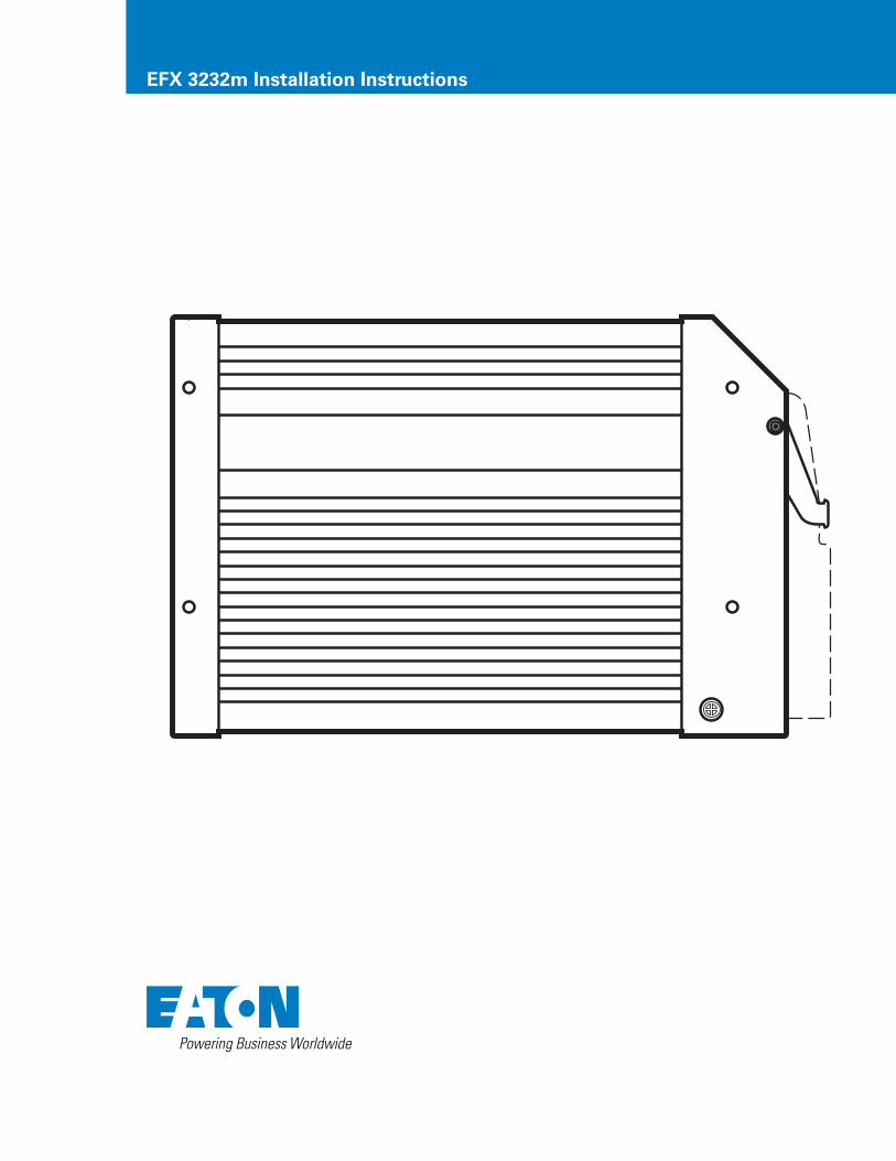
EFX 3232m Installation Instructions
EATON EFX 3232m Installation Manual E-ELCL-TI001-E September 20112
Preliminary Notes ......................................................................................................................................................................... 3
Safety Instructions ....................................................................................................................................................................... 3
Functions and Features ................................................................................................................................................................ 3
Installation .................................................................................................................................................................................... 4
Electrical Connection ................................................................................................................................................................... 4
Setup .......................................................................................................................................................................................... 5
Technical Data .............................................................................................................................................................................. 8
Wiring ........................................................................................................................................................................................ 11
Maintenance, Repair, and Disposal .......................................................................................................................................... 12
Table of Contents
Licences and Trademarks
Microsoft®, Windows®, Windows XP® and Windows Vista® are registered trademarks of Microsoft Corporation.
All trademarks and company names are subject to the copyright of the respective companies.
EATON EFX 3232m Installation Manual E-ELCL-TI001-E September 2011 3
This document covers the Eaton EFX 3232m Mobile Controller and is intended for specialists who are qualified to recognize risks and avoid possible hazards that may be caused during operation or maintenance of the device. It contains information about the correct handling of the device.
Read this document before use to familiarize yourself with operating conditions, installation, and operation. Keep this document during the entire duration of use of the device.
Adhere to all safety instructions.
Symbols
Instruction
> Reaction, result
[…] Designation of pushbuttons, buttons or indications
Cross-reference
Important note: Non-compliance can result in malfunctions or interference.
Information Supplementary note
Warning Icons
Warning: Warning of serious personal injury. Death or serious irreversible injuries may result.
Caution: Warning of personal injury. Slight reversible injuries may result.
Note: Warning of damage to property.
Safety InstructionsGeneral
This description is part of the device. It contains texts and drawings concerning the correct handling of the device and must be read before installation or use.
Observe the operating instructions. Non-observance of the instructions, operation not in accordance with use as prescribed below, wrong installation or incorrect handling can seriously affect the safety of people and machinery.
Target Group
These instructions are intended for authorized persons according to the EMC and low-voltage directives. The device must only be installed, connected and put into operation by a qualified electrician.
Electrical Connection
Disconnect the unit externally before handling it. If necessary, also disconnect any independently supplied output load circuits.
If the device is not supplied by the mobile on-board system (12/24 V battery operation), be sure the external voltage is
generated and supplied according to the criteria for safety extra-low voltage (SELV), since this voltage is supplied without further measures to the connected controller, sensors and actuators.
The wiring of all signals in connection with the SELV circuit of the device must also comply with the SELV criteria (safety extra-low voltage, safe electrical separation from other electric circuits).
If the supplied SELV voltage is externally grounded (SELV becomes PELV), the user must comply with the respective national installation regulations. All statements in this document refer to the device with non-grounded SELV voltage.
The connection terminals may only be supplied with the signals indicated in the technical data and/or on the device label, and only Eaton-approved accessories may be connected.
Housing Temperature
The unit may be operated in a wide operating temperature range, in adherence to the technical specifications. Because of added internal heating, the housing walls may have high perceptible temperatures in hot environments.
Tampering with the Unit
In case of malfunctions or uncertainties, please contact the manufacturer. Tampering with the unit can seriously affect the safety of operators and machinery. It is not permitted and leads to the exclusion of any liability and warranty claims.
Electromagnetic Compatibility
This is a class A installation that can cause radio interference in domestic areas. The operator should take appropriate action as necessary to correct it.
Functions and FeaturesThe freely programmable controllers in the EFX series are rated for use under difficult conditions (e.g. extended temperature range, strong vibration, intensive EMC interference).
They are suited for direct installation in machines in robust mobile applications. Integrated hardware and software functions (operating system) offer high protection for the machine.
The controllers can be used as CANopen master.
Warning: The EFX Series is not approved for safety tasks in the field of safety of persons.
Warning: The user is responsible for the safe function of personally created application programs. If necessary, the user must comply with national regulations for approval tests conducted by supervisory and test organizations.
Preliminary Notes
!
!
!
!
EATON EFX 3232m Installation Manual E-ELCL-TI001-E September 20114
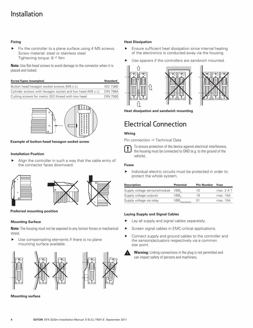
Fixing
Fix the controller to a plane surface using 4 M5 screws. Screw material: steel or stainless steel Tightening torque: 8 ±2 Nm
Note: Use flat-head screws to avoid damage to the connector when it is placed and locked.
Installation Position
Align the controller in such a way that the cable entry of the connector faces downward.
Mounting Surface
Note: The housing must not be exposed to any torsion forces or mechanical stress.
Use compensating elements if there is no plane mounting surface available.
Heat Dissipation
Ensure sufficient heat dissipation since internal heating of the electronics is conducted away via the housing.
Use spacers if the controllers are sandwich mounted.
Electrical ConnectionWiring
Pin connection Technical Data
To ensure protection of the device against electrical interference, the housing must be connected to GND (e.g. to the ground of the vehicle).
Fuses
Individual electric circuits must be protected in order to protect the whole system.
Laying Supply and Signal Cables
Lay all supply and signal cables separately.
Screen signal cables in EMC-critical applications.
Connect supply and ground cables to the controller and the sensors/actuators respectively via a common star point.
Warning: Linking connections in the plug is not permitted and can impact safety of persons and machinery.
Screw Types (examples) Standard
Button head hexagon socket screws (M5 x L) ISO 7380Cylinder screws with hexagon socket and low head (M5 x L) DIN 7984Cutting screws for metric ISO thread with low head DIN 7500
Example of button-head hexagon socket screw
Mounting surface
Heat dissipation and sandwich mounting
Preferred mounting position
Description Potential Pin Number Fuse
Supply voltage sensors/module VBBS 10 max. 2 A TSupply voltage outputs VBBO 19 max. 15ASupply voltage via relay VBBRepeatability 01 max. 15A
!
Installation
EATON EFX 3232m Installation Manual E-ELCL-TI001-E September 2011 5
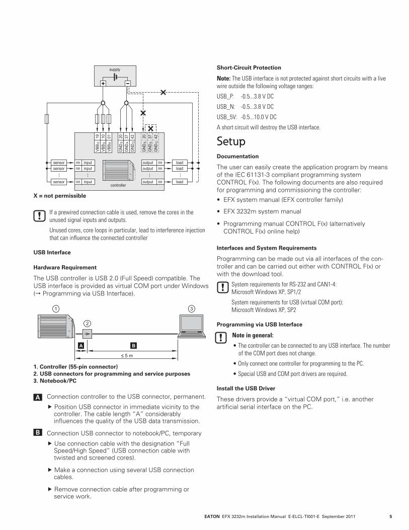
If a prewired connection cable is used, remove the cores in the unused signal inputs and outputs.
Unused cores, core loops in particular, lead to interference injection that can influence the connected controller
USB Interface
Hardware Requirement
The USB controller is USB 2.0 (Full Speed) compatible. The USB interface is provided as virtual COM port under Windows ( Programming via USB Interface).
Connection controller to the USB connector, permanent.
Position USB connector in immediate vicinity to the controller. The cable length “A” considerably influences the quality of the USB data transmission.
Connection USB connector to notebook/PC, temporary
Use connection cable with the designation “Full Speed/High Speed” (USB connection cable with twisted and screened cores).
Make a connection using several USB connection cables.
Remove connection cable after programming or service work.
Short-Circuit Protection
Note: The USB interface is not protected against short circuits with a live wire outside the following voltage ranges:
USB_P: -0.5...3.8 V DC
USB_N: -0.5...3.8 V DC
USB_5V: -0.5...10.0 V DC
A short circuit will destroy the USB interface.
SetupDocumentation
The user can easily create the application program by means of the IEC 61131-3 compliant programming system CONTROL F(x). The following documents are also required for programming and commissioning the controller:
• EFX system manual (EFX controller family)
• EFX 3232m system manual
• Programming manual CONTROL F(x) (alternatively CONTROL F(x) online help)
Interfaces and System Requirements
Programming can be made out via all interfaces of the con-troller and can be carried out either with CONTROL F(x) or with the download tool.
System requirements for RS-232 and CAN1-4: Microsoft Windows XP, SP1/2
System requirements for USB (virtual COM port): Microsoft Windows XP, SP2
Programming via USB Interface
Note in general:
• The controller can be connected to any USB interface. The number of the COM port does not change.
• Only connect one controller for programming to the PC.
• Special USB and COM port drivers are required.
Install the USB Driver
These drivers provide a “virtual COM port,” i.e. another artificial serial interface on the PC.
X = not permissible
1. Controller (55-pin connector) 2. USB connectors for programming and service purposes 3. Notebook/PC
A
B
EATON EFX 3232m Installation Manual E-ELCL-TI001-E September 20116
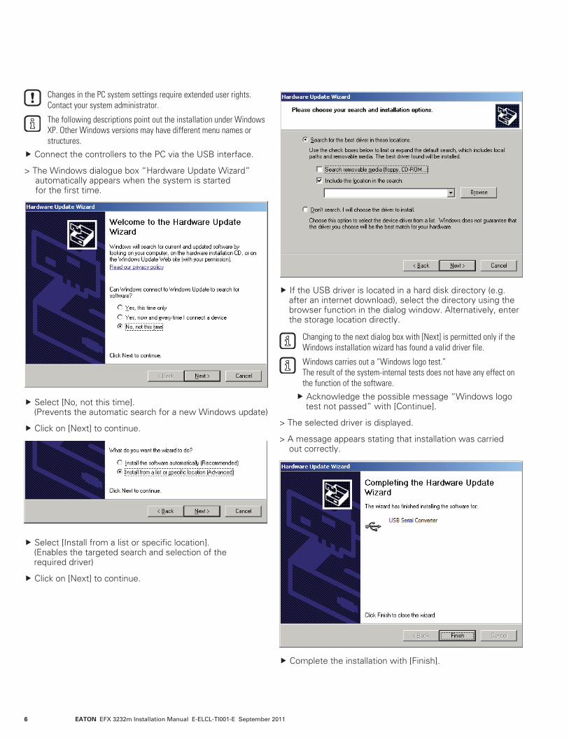
Changes in the PC system settings require extended user rights. Contact your system administrator.
The following descriptions point out the installation under Windows XP. Other Windows versions may have different menu names or structures.
Connect the controllers to the PC via the USB interface.
> The Windows dialogue box “Hardware Update Wizard” automatically appears when the system is started for the first time.
•
Select [No, not this time]. (Prevents the automatic search for a new Windows update)
Click on [Next] to continue.
Select [Install from a list or specific location]. (Enables the targeted search and selection of the required driver)
Click on [Next] to continue.
•
•
•
•
•
•
•
•
•
•
•
•
If the USB driver is located in a hard disk directory (e.g. after an internet download), select the directory using the browser function in the dialog window. Alternatively, enter the storage location directly.
Changing to the next dialog box with [Next] is permitted only if the Windows installation wizard has found a valid driver file.
Windows carries out a “Windows logo test.” The result of the system-internal tests does not have any effect on the function of the software.
Acknowledge the possible message “Windows logo test not passed” with [Continue].
> The selected driver is displayed.
> A message appears stating that installation was carried out correctly.
•
Complete the installation with [Finish].
EATON EFX 3232m Installation Manual E-ELCL-TI001-E September 2011 7
Install and Define the Virtual COM Port
The installation is only necessary when started for the first time. The installation procedure is identical to the previous USB driver installation.
The installation program automatically selects the next free COM port (e.g. COM3) for the driver.
In case of conflicts with other programs, change the setting for the COM port in the Windows device manager.
1. Open the device manager. The service program device manager can, for example, be accessed via Start Control Panel Device Manager.
2. Select the entry with a double click in the directory “Ports (COM & LPT).” As an alternative: Right mouse click Properties.
3. Click on [Port settings] in the following dialog box.
4. Select [“Advanced…”] and redefine the COM port in the “Advanced Settings” menu (e.g. COM8), if necessary.
Do not use a COM port that is already being used by another device. In most computers, COM1 and COM2 are already assigned by the hardware interfaces.
Confirm the setting with [OK].
> The new COM port is indicated in the device manager following the driver name.
Deinstall the Driver
If a driver needs to be updated, the installed drivers have to be deinstalled first.
Disconnect the USB connection between the controller and the PC.
Open the service program “Software” via the start menu Control Panel.
Deinstall the drivers successively with [Change/Remove].
EATON EFX 3232m Installation Manual E-ELCL-TI001-E September 20118
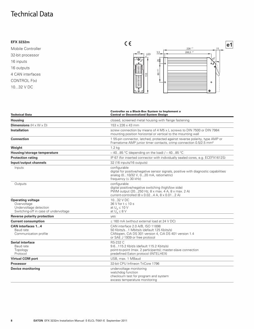
EFX 3232m
Mobile Controller
32-bit processor
16 inputs
16 outputs
4 CAN interfaces
CONTROL F(x)
10...32 V DC
Controller as a Black-Box System to Implement a Technical Data Central or Decentralized System Design
Housing closed, screened metal housing with flange fasteningDimensions (H x W x D) 153 x 226 x 43 mmInstallation screw connection by means of 4 M5 x L screws to DIN 7500 or DIN 7984 mounting position horizontal or vertical to the mounting wallConnection 1 55-pin connector, latched, protected against reverse polarity, type AMP or Framatome AMP junior timer contacts, crimp connection 0.5/2.5 mm²Weight 1.2 kgHousing/storage temperature – 40...85 °C (depending on the load) / – 40...85 °CProtection rating IP 67 (for inserted connector with individually sealed cores, e.g. ECEFX1612S)Input/output channels 32 (16 inputs/16 outputs) Inputs configurable digital for positive/negative sensor signals, positive with diagnostic capabilities analog (0...10/32 V, 0...20 mA, ratiometric) frequency (≤ 30 kHz) Outputs configurable digital positive/negative switching (high/low side) PWM output (20...250 Hz, 8 x max. 4 A, 8 x max. 2 A) current-controlled (8 x 0.02...4 A, 8 x 0.01...2 A)Operating voltage 10...32 V DC Overvoltage 36 V for t ≤ 10 s Undervoltage detection at UB ≤ 10 V Switching-off in case of undervoltage at UB ≤ 8 VReverse polarity protection yesCurrent consumption ≤ 160 mA (without external load at 24 V DC)CAN interfaces 1...4 CAN interface 2.0 A/B, ISO 11898 Baud rate 50 Kbits/s...1 Mbits/s (default 125 Kbits/s) Communication profile CANopen, CiA DS 301 version 4, CiA DS 401 version 1.4 or SAE J 1939 or free protocolSerial interface RS-232 C Baud rate 9.6...115.2 Kbit/s (default 115.2 Kbits/s) Topology point-to-point (max. 2 participants); master-slave connection Protocol predefined Eaton protocol (INTELHEX)Virtual COM port USB, max. 1 MBaudProcessor 32-bit CPU Infineon TriCore 1796Device monitoring undervoltage monitoring watchdog function checksum test for program and system excess temperature monitoring
Technical Data
EATON EFX 3232m Installation Manual E-ELCL-TI001-E September 2011 9
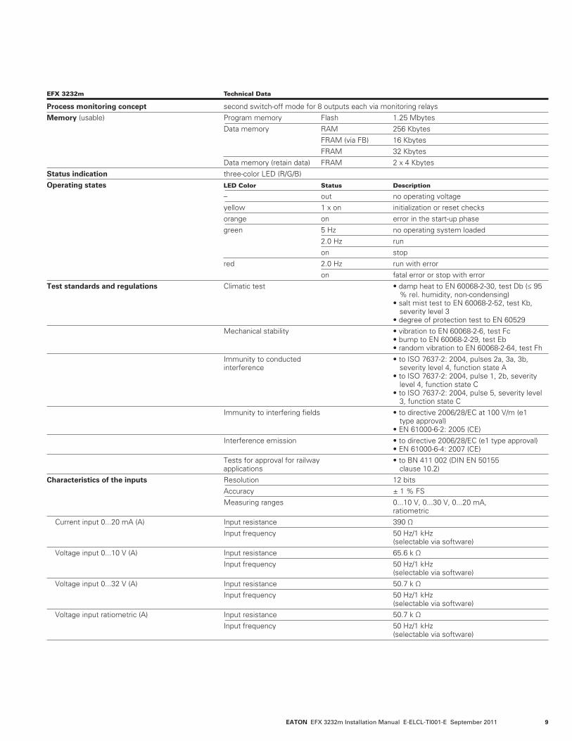
EFX 3232m Technical Data
Process monitoring concept second switch-off mode for 8 outputs each via monitoring relaysMemory (usable) Program memory Flash 1.25 Mbytes Data memory RAM 256 Kbytes FRAM (via FB) 16 Kbytes FRAM 32 Kbytes Data memory (retain data) FRAM 2 x 4 KbytesStatus indication three-color LED (R/G/B) Operating states LED Color Status Description
– out no operating voltage yellow 1 x on initialization or reset checks orange on error in the start-up phase green 5 Hz no operating system loaded 2.0 Hz run on stop red 2.0 Hz run with error on fatal error or stop with errorTest standards and regulations Climatictest •dampheattoEN60068-2-30,testDb(≤95 % rel. humidity, non-condensing) •saltmisttesttoEN60068-2-52,testKb, severity level 3 •degreeofprotectiontesttoEN60529 Mechanicalstability •vibrationtoEN60068-2-6,testFc •bumptoEN60068-2-29,testEb •randomvibrationtoEN60068-2-64,testFh Immunitytoconducted •toISO7637-2:2004,pulses2a,3a,3b, interference severity level 4, function state A •toISO7637-2:2004,pulse1,2b,severity level 4, function state C •toISO7637-2:2004,pulse5,severitylevel 3, function state C Immunitytointerferingfields •todirective2006/28/ECat100V/m(e1 type approval) •EN61000-6-2:2005(CE) Interferenceemission •todirective2006/28/EC(e1typeapproval) •EN61000-6-4:2007(CE) Testsforapprovalforrailway •toBN411002(DINEN50155 applications clause 10.2) Characteristics of the inputs Resolution 12 bits Accuracy ± 1 % FS Measuring ranges 0...10 V, 0...30 V, 0...20 mA, ratiometric Current input 0...20 mA (A) Input resistance 390 Ω Input frequency 50 Hz/1 kHz (selectable via software) Voltage input 0...10 V (A) Input resistance 65.6 k Ω Input frequency 50 Hz/1 kHz (selectable via software) Voltage input 0...32 V (A) Input resistance 50.7 k Ω Input frequency 50 Hz/1 kHz (selectable via software) Voltage input ratiometric (A) Input resistance 50.7 k Ω Input frequency 50 Hz/1 kHz (selectable via software)
EATON EFX 3232m Installation Manual E-ELCL-TI001-E September 201110
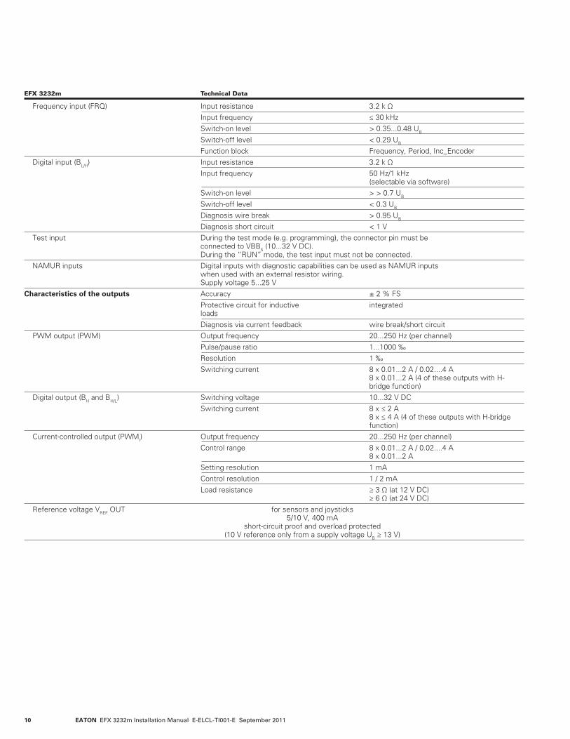
EFX 3232m Technical Data
Frequency input (FRQ) Input resistance 3.2 k Ω Input frequency ≤ 30 kHz Switch-on level > 0.35...0.48 UB
Switch-off level < 0.29 UB
Function block Frequency, Period, Inc_Encoder Digital input (BL/H) Input resistance 3.2 k Ω Input frequency 50 Hz/1 kHz (selectable via software) Switch-on level > > 0.7 UB
Switch-off level < 0.3 UB
Diagnosis wire break > 0.95 UB
Diagnosis short circuit < 1 V Test input During the test mode (e.g. programming), the connector pin must be connected to VBBS (10...32 V DC). During the “RUN” mode, the test input must not be connected. NAMUR inputs Digital inputs with diagnostic capabilities can be used as NAMUR inputs when used with an external resistor wiring. Supply voltage 5...25 VCharacteristics of the outputs Accuracy ± 2 % FS Protective circuit for inductive integrated loads Diagnosis via current feedback wire break/short circuit PWM output (PWM) Output frequency 20...250 Hz (per channel) Pulse/pause ratio 1...1000 ‰ Resolution 1 ‰ Switching current 8 x 0.01...2 A / 0.02....4 A 8 x 0.01...2 A (4 of these outputs with H- bridge function) Digital output (BH and BH/L) Switching voltage 10...32 V DC Switching current 8 x ≤ 2 A 8 x ≤ 4 A (4 of these outputs with H-bridge function) Current-controlled output (PWMI) Output frequency 20...250 Hz (per channel) Control range 8 x 0.01...2 A / 0.02....4 A 8 x 0.01...2 A Setting resolution 1 mA Control resolution 1 / 2 mA Load resistance ≥ 3 Ω (at 12 V DC) ≥ 6 Ω (at 24 V DC) Reference voltage VREF OUT for sensors and joysticks 5/10 V, 400 mA short-circuit proof and overload protected (10 V reference only from a supply voltage UB ≥ 13 V)
EATON EFX 3232m Installation Manual E-ELCL-TI001-E September 2011 11
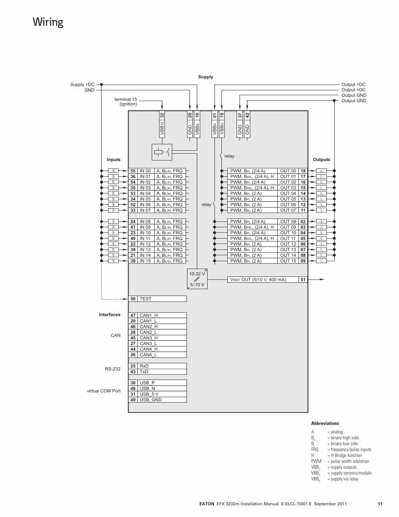
Wiring
Abbreviations
A = analog BH = binary high side BL = binary low side FRQ = frequency/pulse inputs H = H-Bridge function PWM = pulse width odulation VBBO = supply outputs VBBS = supply sensors/module VBBR = supply via relay

EATON EFX 3232m Installation Manual E-ELCL-TI001-E September 201112
The device is maintenance-free.
Do not open the housing, as the device does not contain any components that must be maintained by the user. The device must be repaired only by the manufacturer.
Dispose of the device in accordance with national environmental regulations.
Maintenance, Repair, and Disposal
Eaton Hydraulics Group USA 14615 Lone Oak Road Eden Prairie, MN 55344 USA Tel: 952-937-9800 Fax: 952-294-7722 www.eaton.com/hydraulics
Eaton Hydraulics Group Europe Route de la Longeraie 7 1110 Morges Switzerland Tel: +41 (0) 21 811 4600 Fax: +41 (0) 21 811 4601
Eaton Hydraulics Group Asia Pacific Eaton Building 4th Floor, No. 3 Lane 280 Linhong Rd. Changning District Shanghai 200335 China Tel: (+86 21) 5200 0099 Fax: (+86 21) 5200 0400
© 2011 Eaton Corporation All Rights Reserved Printed in USA Document No. E-ELCL-TI001-E September 2011