Embed Size (px)
Citation preview
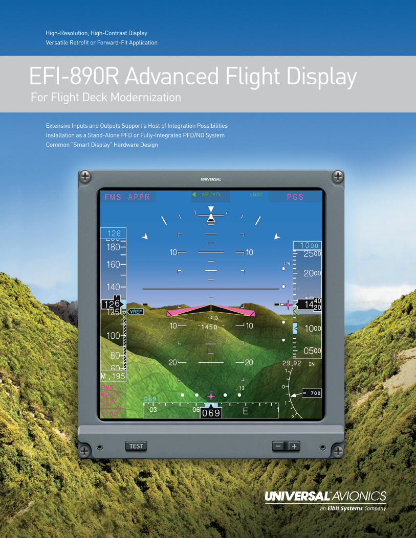
EFI-890R Advanced Flight Display For Flight Deck Modernization
High-Resolution, High-Contrast Display Versatile Retrofit or Forward-Fit Application
Extensive Inputs and Outputs Support a Host of Integration Possibilities Installation as a Stand-Alone PFD or Fully-Integrated PFD/ND SystemCommon “Smart Display” Hardware Design
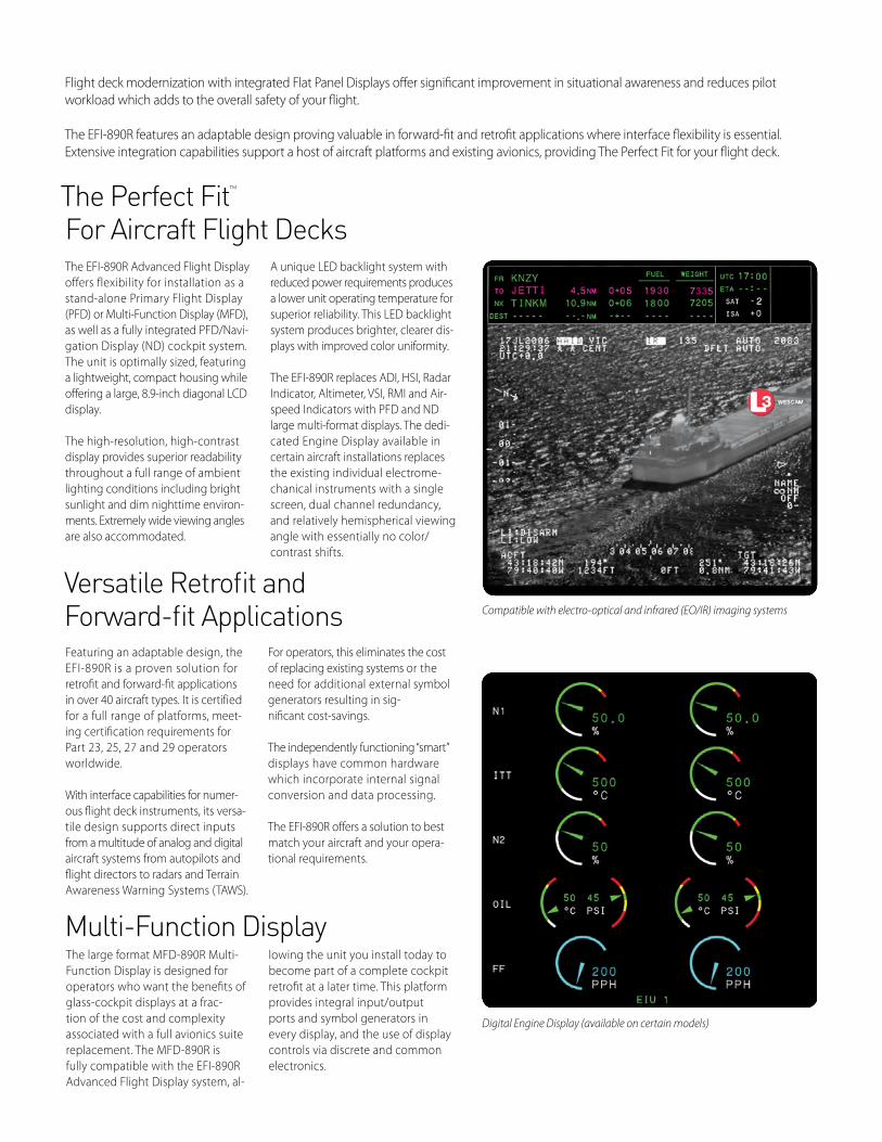
Compatible with electro-optical and infrared (EO/IR) imaging systems
Digital Engine Display (available on certain models)
The EFI-890R Advanced Flight Display offers flexibility for installation as a stand-alone Primary Flight Display (PFD) or Multi-Function Display (MFD), as well as a fully integrated PFD/Navi-gation Display (ND) cockpit system. The unit is optimally sized, featuring a lightweight, compact housing while offering a large, 8.9-inch diagonal LCD display.
The high-resolution, high-contrast display provides superior readability throughout a full range of ambient lighting conditions including bright sunlight and dim nighttime environ- ments. Extremely wide viewing angles are also accommodated.
A unique LED backlight system with reduced power requirements produces a lower unit operating temperature for superior reliability. This LED backlight system produces brighter, clearer dis-plays with improved color uniformity.
The EFI-890R replaces ADI, HSI, Radar Indicator, Altimeter, VSI, RMI and Air-speed Indicators with PFD and ND large multi-format displays. The dedi-cated Engine Display available in certain aircraft installations replaces the existing individual electrome-chanical instruments with a single screen, dual channel redundancy, and relatively hemispherical viewing angle with essentially no color/contrast shifts.
The Perfect Fit™ For Aircraft Flight Decks
Versatile Retrofit andForward-fit Applications
Multi-Function Display
Featuring an adaptable design, the EFI-890R is a proven solution for retrofit and forward-fit applications in over 40 aircraft types. It is certified for a full range of platforms, meet-ing certification requirements for Part 23, 25, 27 and 29 operators worldwide.
With interface capabilities for numer-ous flight deck instruments, its versa-tile design supports direct inputs from a multitude of analog and digital aircraft systems from autopilots and flight directors to radars and Terrain Awareness Warning Systems (TAWS).
For operators, this eliminates the cost of replacing existing systems or the need for additional external symbol generators resulting in sig-nificant cost-savings.
The independently functioning “smart” displays have common hardware which incorporate internal signal conversion and data processing.
The EFI-890R offers a solution to best match your aircraft and your opera-tional requirements.
The large format MFD-890R Multi-Function Display is designed for operators who want the benefits of glass-cockpit displays at a frac-tion of the cost and complexity associated with a full avionics suite replacement. The MFD-890R is fully compatible with the EFI-890R Advanced Flight Display system, al-
lowing the unit you install today to become part of a complete cockpit retrofit at a later time. This platform provides integral input/output ports and symbol generators in every display, and the use of display controls via discrete and common electronics.
Flight deck modernization with integrated Flat Panel Displays offer significant improvement in situational awareness and reduces pilot workload which adds to the overall safety of your flight.
The EFI-890R features an adaptable design proving valuable in forward-fit and retrofit applications where interface flexibility is essential. Extensive integration capabilities support a host of aircraft platforms and existing avionics, providing The Perfect Fit for your flight deck.
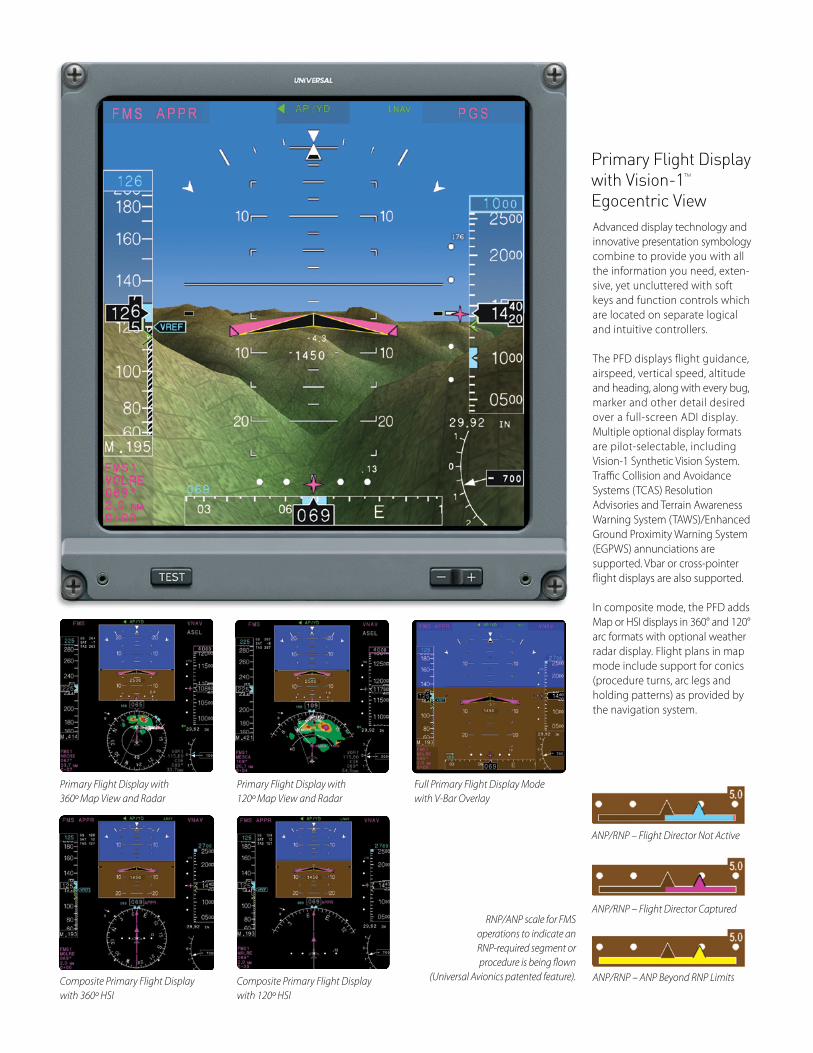
Primary Flight Display with 360º Map View and Radar
Composite Primary Flight Display with 360º HSI
Primary Flight Display with 120º Map View and Radar
Composite Primary Flight Display with 120º HSI
Full Primary Flight Display Mode with V-Bar Overlay
Primary Flight Display with Vision-1™
Egocentric ViewAdvanced display technology and innovative presentation symbology combine to provide you with all the information you need, exten-sive, yet uncluttered with soft keys and function controls which are located on separate logical and intuitive controllers.
The PFD displays flight guidance, airspeed, vertical speed, altitude and heading, along with every bug, marker and other detail desired over a full-screen ADI display. Multiple optional display formats are pilot-selectable, including Vision-1 Synthetic Vision System. Traffic Collision and Avoidance Systems (TCAS) Resolution Advisories and Terrain Awareness Warning System (TAWS)/Enhanced Ground Proximity Warning System (EGPWS) annunciations are supported. Vbar or cross-pointer flight displays are also supported.
In composite mode, the PFD adds Map or HSI displays in 360° and 120° arc formats with optional weather radar display. Flight plans in map mode include support for conics (procedure turns, arc legs and holding patterns) as provided by the navigation system.
ANP/RNP – Flight Director Not Active
ANP/RNP – ANP Beyond RNP Limits
ANP/RNP – Flight Director CapturedRNP/ANP scale for FMS
operations to indicate an RNP-required segment or procedure is being flown
(Universal Avionics patented feature).
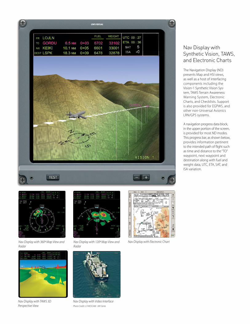
Nav Display with 360º Map View and Radar
Nav Display with 120º Map View and Radar
Nav Display with Electronic Chart
Nav Display with TAWS 3D Perspective View
Nav Display with Synthetic Vision, TAWS,and Electronic Charts
The Navigation Display (ND) presents Map and HSI views, as well as a host of interfacing components including the Vision-1 Synthetic Vision Sys-tem, TAWS Terrain Awareness Warning System, Electronic Charts, and Checklists. Support is also provided for EGPWS, and other non-Universal Avionics LRN/GPS systems.
A navigation progress data block, in the upper portion of the screen, is provided for most ND modes. This progress bar, as shown below, provides information pertinent to the intended path of flight such as time and distance to the “TO” waypoint, next waypoint and destination along with fuel and weight data, UTC, ETA, SAT, and ISA variation.
Nav Display with Video InterfacePhoto Credit: L-3 WESCAM - MX Series
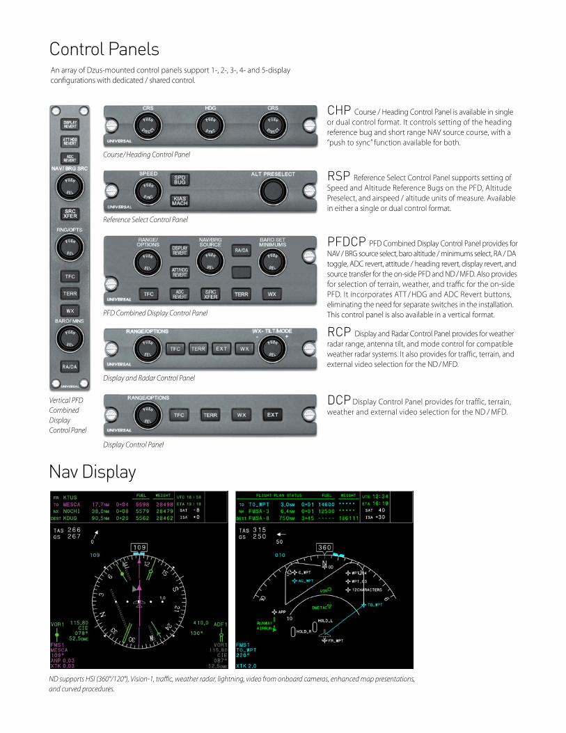
Course / Heading Control Panel
Reference Select Control Panel
PFD Combined Display Control Panel
Display and Radar Control Panel
Display Control Panel
Vertical PFD Combined Display Control Panel
CHP Course / Heading Control Panel is available in single or dual control format. It controls setting of the heading reference bug and short range NAV source course, with a “push to sync” function available for both.
RSP Reference Select Control Panel supports setting of Speed and Altitude Reference Bugs on the PFD, Alti tude Preselect, and airspeed / altitude units of measure. Available in either a single or dual control format.
PFDCP PFD Combined Display Control Panel provides for NAV / BRG source select, baro altitude / minimums select, RA / DA toggle, ADC revert, attitude / heading revert, display revert, and source transfer for the on-side PFD and ND / MFD. Also provides for selection of terrain, weather, and traffic for the on-side PFD. It incorporates ATT / HDG and ADC Revert buttons, eliminating the need for separate switches in the installation. This control panel is also available in a vertical format.
RCP Display and Radar Control Panel provides for weather radar range, antenna tilt, and mode control for compatible weather radar systems. It also provides for traffic, terrain, and external video selection for the ND / MFD.
DCP Display Control Panel provides for traffic, terrain, weather and external video selection for the ND / MFD.
ND supports HSI (360°/120°), Vision-1, traffic, weather radar, lightning, video from onboard cameras, enhanced map presentations, and curved procedures.
Control Panels An array of Dzus-mounted control panels support 1-, 2-, 3-, 4- and 5-display configurations with dedicated / shared control.
Nav Display
Specifications and graphic displays contained herein are subject to change without notice.Features and capabilities may be limited due to installation or interfacing equipment.
JeppView Chart reproduced with permission of Jeppesen Sanderson, Inc. NOT FOR NAVIGATIONAL USE. ©Jeppesen Sanderson, Inc. 2018.
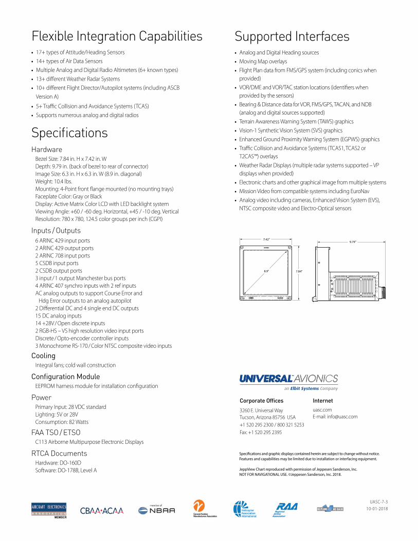
7.42”
7.84”8.9”
9.79”
SpecificationsHardware Bezel Size: 7.84 in. H x 7.42 in. W Depth: 9.79 in. (back of bezel to rear of connector) Image Size: 6.3 in. H x 6.3 in. W (8.9 in. diagonal) Weight: 10.4 lbs. Mounting: 4-Point front flange mounted (no mounting trays) Faceplate Color: Gray or Black Display: Active Matrix Color LCD with LED backlight system Viewing Angle: +60 / -60 deg. Horizontal, +45 / -10 deg. Vertical Resolution: 780 x 780, 124.5 color groups per inch (CGPI)
Inputs / Outputs 6 ARINC 429 input ports 2 ARINC 429 output ports 2 ARINC 708 input ports 5 CSDB input ports 2 CSDB output ports 3 input / 1 output Manchester bus ports 4 ARINC 407 synchro inputs with 2 ref inputs AC analog outputs to support Course Error and Hdg Error outputs to an analog autopilot 2 Differential DC and 4 single end DC outputs 15 DC analog inputs 14 +28V / Open discrete inputs 2 RGB-HS – VS high resolution video input ports Discrete / Opto-encoder controller inputs 3 Monochrome RS-170 / Color NTSC composite video inputs
Cooling Integral fans; cold wall construction
Configuration Module EEPROM harness module for installation configuration
Power Primary Input: 28 VDC standard Lighting: 5V or 28V Consumption: 82 Watts
FAA TSO / ETSO C113 Airborne Multipurpose Electronic Displays
RTCA Documents Hardware: DO-160D Software: DO-178B, Level A
Supported Interfaces• Analog and Digital Heading sources
• Moving Map overlays
• Flight Plan data from FMS/GPS system (including conics when provided)
• VOR/DME and VOR/TAC station locations (identifiers when provided by the sensors)
• Bearing & Distance data for VOR, FMS/GPS, TACAN, and NDB (analog and digital sources supported)
• Terrain Awareness Warning System (TAWS) graphics
• Vision-1 Synthetic Vision System (SVS) graphics
• Enhanced Ground Proximity Warning System (EGPWS) graphics
• Traffic Collision and Avoidance Systems (TCAS1, TCAS2 or T2CAS™) overlays
• Weather Radar Displays (multiple radar systems supported – VP displays when provided)
• Electronic charts and other graphical image from multiple systems
• Mission Video from compatible systems including EuroNav
• Analog video including cameras, Enhanced Vision System (EVS), NTSC composite video and Electro-Optical sensors
Flexible Integration Capabilities• 17+ types of Attitude/Heading Sensors
• 14+ types of Air Data Sensors
• Multiple Analog and Digital Radio Altimeters (6+ known types)
• 13+ different Weather Radar Systems
• 10+ different Flight Director/Autopilot systems (including ASCB Version A)
• 5+ Traffic Collision and Avoidance Systems (TCAS)
• Supports numerous analog and digital radios
UASC-7-310-01-2018
Corporate Offices
3260 E. Universal WayTucson, Arizona 85756 USA+1 520 295 2300 / 800 321 5253Fax: +1 520 295 2395
Internetuasc.comE-mail: [email protected]