Embed Size (px)
Citation preview

Abstract
In this paper, the authors present an energy efficiency
study of Variable-Speed Drives for Single-Phase Induction
Motors. The objective was to evaluate popular variable-
speed drive schemes as they operate in their most efficient
mode under different loading conditions. The considered
schemes included phase control, variable-frequency drives
and voltage control. This study focused on the development
of experimental test methodologies to characterize motors
and implement desired control schemes. Mathematical mod-
eling and computer simulations were also utilized for engi-
neering design and analysis. The fan load application was
considered for further illustration of the developed method-
ology. This study provides a general framework for the
evaluation and selection of variable-speed drives.
Introduction
Speed control of AC motors evolved very rapidly with
advances in power electronics technology [1]. Applications
that were dominated by DC motors became most suited for
AC motors as a more economical alternative. Three-phase
motors, however, were the prime candidates for initial de-
velopments for their more significant impact on high-power
industrial applications. With the maturing of three-phase
motor drives, technologies started to find their way to single
-phase motor applications which constitute the largest per-
centage of electric power consumption in commercial and
residential applications. AC Single-Phase Induction Motors
(SPIMs) are popular for their low cost and versatility. Com-
pared to three-phase induction motors, single-phase motors
lack the self-starting capabilities and they are more sensitive
to loading conditions.
For applications with varying loads, a variable-speed
drive is a must since it can achieve up to 50% in energy
savings. This principle often applies to machines that need
to be constantly starting. By means of variable-speed drives,
it is possible to regulate the starting current of such ma-
chines and, therefore, save more energy [2]. There are three
commonly known techniques for AC motor drives; namely,
variable frequency [3], voltage control [4], [5] and variable
rotor resistance. Several studies have been conducted to
analyze the performance of the different drives.
Nomenclature
In this paper, the theory behind the steady-state operation
of SPIM is presented and was used for the mathematical
models development in this study. Experimental tests were
then performed in order to determine the motor parameters.
The torque-speed motor characteristic was used to validate
experimental results of the motor-winding parameters. Pow-
er consumption under different loading conditions was ana-
EFFICIENT DRIVES FOR SINGLE-PHASE AC MOTORS:
ANALYSIS AND APPLICATIONS
——————————————————————————————————————————————–————
Juan F. Gallego-Calderon, California State University Fresno; Nagy Bengiamin, California State University Fresno
R1, X1 Resistance and reactance of the stator
R'2, X’2 Resistance and reactance of the rotor
Xm Mutual reactance
τind Induced torque
VTH, RTH Thévenin voltage and resistance
ωm, ωsync Motor speed and synchronous speed in
rad/sec
I Stator current
ZF, ZB Forward and backward impedance
Pin, Pout Input and output power
PAG, PAG,F,
PAG,B
Air-gap power: total, forward and back-
ward
Pconv Converted power
PRCL Core losses
Prot Rotational losses
Ps Power savings
f Line frequency in Hz (ω=2πf)
V Phase voltage
τ Torque
nm, nsync Motor speed and synchronous speed in
rpm
s Slip
p.f. Power factor
η Efficiency
——————————————————————————————————————————————————–
EFFICIENT DRIVES FOR SINGLE-PHASE AC MOTORS: ANALYSIS AND APPLICATIONS 25

——————————————————————————————————————————————–————
——————————————————————————————————————————————–————
26 INTERNATIONAL JOURNAL OF MODERN ENGINEERING | VOLUME 13, NUMBER 2, SPRING/SUMMER 2013
lyzed experimentally and via modeling techniques for dif-
ferent control schemes under varying loading conditions to
find the optimal mode of operation. Moreover, the fan appli-
cation was analyzed in order to provide a real-life applica-
tion where this kind of analysis is important for energy effi-
ciency.
Induction-Motor Model
In applications where there is insufficient information
available about the motor parameters, such as winding re-
sistance and inductance, it is necessary to execute the fol-
lowing three classical tests: DC test, locked-rotor test and
the no-load test. These experimental tests are based on the
single-phase induction-motor static RC equivalent circuit
model presented in Figure 1. This model is based on the
double-revolving-field theory. This theory states that a sta-
tionary pulsating magnetic field can be expressed as two
rotating magnetic fields (forward and backward) of the
same magnitude but with different direction. The effective
torque that is produced is then practically equal to the re-
sultant sum of the torque components due to each of the two
magnetic fields [6].
Figure 1. Equivalent Circuit of a Single-Phase Induction
Motor
Since the purpose of this study was to analyze the energy
efficiency of the drives discussed earlier, it was not neces-
sary to analyze the dynamics of the induction motor. This is
where the d-q model would have been necessary. The motor
-winding parameters found experimentally are shown in
Table 1.
This section describes the relationship of the motor’s
torque, power and speed. Chapman [6] derived the formula
that describes the induced torque from an analysis of the
three-phase motor’s equivalent circuit. This formula can be
applied to the single-phase motor using a 1/3 scaling factor
since the torque is additive. Thus, this formula was applied
here using the parameters presented in Table 1. In addition,
the ideal torque-speed characteristic was compared with
experimental data for validity.
Table 1. Induction-Motor Parameters
It should be noted from Equation (1) that the produced
torque is dependent on the slip (motor speed), operating
frequency as it affects the reactance (X=jωL), and the phase
voltage, Vϕ. The resistance also plays a role, but it was as-
sumed constant for purposes of this study. Most economical
SPIMs are of the squirrel-cage type, where the rotor re-
sistance is practically fixed. Wound-rotor motors may pro-
vide access terminals to change their effective rotor re-
sistance. The dependence of τind on nm, Vϕ, f and R2 permits
the reverse logic of adjusting nm for a given τind (load) using
Vϕ and f.
(1)
where
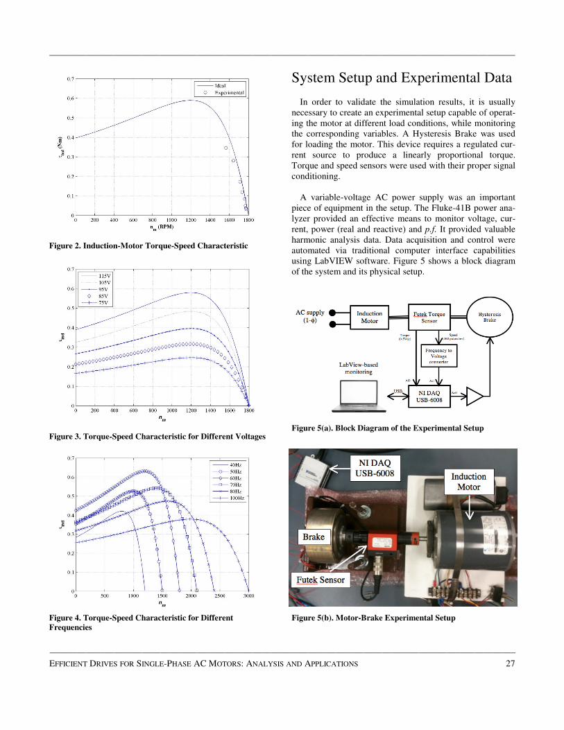
Equation (1) was utilized to create the torque-speed char-
acteristic curve presented in Figure 2, where s = (nm-nsync)/
nsync. In physical experiments, the motor was operated under
a variable load and the torque was measured at the corre-
sponding speeds (see Figure 2). The rated motor voltage
(115 V) and nominal frequency (60 Hz) were used in this
test. Figures 3 and 4 show the simulation results for the
same motor for variable f and Vϕ, respectively.
Parameter Value
Main winding stator resistance (ohms) 15.8971
Main winding stator/rotor reactance (ohms) 17.9800
Main winding stator/rotor inductance (H) 0.0477
Main winding rotor resistance (ohms) 12.7190
Main winding mutual reactance (ohms) 223.1849
Main winding mutual inductance (H) 0.5920
——————————————————————————————————————————————–————
Figure 2. Induction-Motor Torque-Speed Characteristic
Figure 3. Torque-Speed Characteristic for Different Voltages
Figure 4. Torque-Speed Characteristic for Different
Frequencies
System Setup and Experimental Data
In order to validate the simulation results, it is usually
necessary to create an experimental setup capable of operat-
ing the motor at different load conditions, while monitoring
the corresponding variables. A Hysteresis Brake was used
for loading the motor. This device requires a regulated cur-
rent source to produce a linearly proportional torque.
Torque and speed sensors were used with their proper signal
conditioning.
A variable-voltage AC power supply was an important
piece of equipment in the setup. The Fluke-41B power ana-
lyzer provided an effective means to monitor voltage, cur-
rent, power (real and reactive) and p.f. It provided valuable
harmonic analysis data. Data acquisition and control were
automated via traditional computer interface capabilities
using LabVIEW software. Figure 5 shows a block diagram
of the system and its physical setup.
Figure 5(a). Block Diagram of the Experimental Setup
Figure 5(b). Motor-Brake Experimental Setup
——————————————————————————————————————————————————–
EFFICIENT DRIVES FOR SINGLE-PHASE AC MOTORS: ANALYSIS AND APPLICATIONS 27

——————————————————————————————————————————————–————
——————————————————————————————————————————————–————
28 INTERNATIONAL JOURNAL OF MODERN ENGINEERING | VOLUME 13, NUMBER 2, SPRING/SUMMER 2013
Power Consumption
With the model of Figure 1 in mind, it is important to
understand the power flow of a single-phase induction mo-
tor in order to analyze the data collected experimentally and
validate simulation results. The calculated input power from
Equations (2) and (3) corresponds to the power consump-
tion of the motor, where V is the input voltage. Then, the
first type of loss appears as stator copper loss, which corre-
sponds to the power dissipated through the stator resistance,
R1. The power present in the air-gap is dissipated through
the rotor resistance and is defined as PAG in Equation(4).
After some power is lost in the rotor, PRC, the remaining
power corresponds to the power converted from electrical to
mechanical (Pconv); see Equations (5) and (6). The output
and rotor powers are then given by Equations (7) and (8).
Using the induction-motor parameters presented in Table 1,
the motor was simulated under three different loading con-
ditions in order to find the power consumption, the output
power and the power converted from electrical to mechani-
cal. These simulations were compared with the results ob-
tained experimentally for model verification and are pre-
sented in Figure 6. These results demonstrate the validity of
the mathematical model including the identified motor pa-
rameters.
Figure 6. Power Consumption under Different Loading
Conditions
Moreover, the model was validated through the experi-
mental results obtained for the 120V, 100V and 80V voltage
levels. Each voltage condition was tested over the torque
range allowed by the motor. As the load increases, the speed
and the slip change. Using these conditions, the values of R
and L were determined for each case to conduct the simula-
tions. The speed was measured experimentally and was then
used to calculate the output power generated by the motor.
In addition, the speed was used to calculate the slip used for
the simulations. The results are presented in Figures 7-10.
(2)
(3)
(4)
(5)
(6)
(7)
(8)
Figure 7. Power-Flow Representation over the Speed Range of
Operation when Load is 0.038Nm
Figure 8. Power Consumption at 120Vrms

——————————————————————————————————————————————–————
Figure 9. Power Consumption at 100Vrms
Figure 10. Power Consumption at 80Vrms
Energy Efficiency
The efficiency of the induction motor depends on several
design parameters and factors that are part of the manufac-
turing process [7]. The motivation for producing high-
efficiency motors is to reduce the operational costs of the
machines over time. This study intended to develop a strate-
gy for characterizing induction motors through simulations
and experimental results, with the ultimate goal of finding
the efficiency of the motor over a possible range of opera-
tion. In the previous section, the results showed the perfor-
mance of the motor from a power-consumption point of
view.
The efficiency results, experimental and simulated, ob-
tained for a variation of the supply voltage and maintaining
the operating frequency at 60Hz, are presented in Figure 11.
Under these conditions, when the motor is operated near its
rated condition (higher load and rated voltage), it achieves
the most efficient mode of operation, as expected. Thus,
notice that once again the steady-state model is a good ap-
proximation of the induction motor.
Figure 11. Efficiency under Different Loading Conditions
(Operating at 60Hz)
Optimum Mode of Operation
The phase-control technique (control of the conduction
angle) has a negative impact on the performance of the sys-
tem due to the inherent presence of harmonics [8]. The To-
tal Harmonic Distortion Ratio (THD-R) increases with the
increment of the conduction angle. In addition, it was ob-
served that when the motor was operating at certain voltag-
es, and the load was increased, the THD-R also increased
and the overall performance of the system diminished. Ex-
perimental tests were carried out to find the effects of this
degradation on the efficiency of the motor under different
loading conditions. The data presented in Table 2 show the
experimental results using phase control over a range of
loads, while operating at 100V.
Table 2. Experimental Results – Phase Control Operating at
100 V
Load
(Nm)
nm (rpm) Pout
(W)
Pin
(W)
η
(%)
THD-R
(%)
0.05 1706 8.9326 36 24.81276 29.0
0.10 1674 17.5301 49 35.77569 29.2
0.15 1642 25.7925 62 41.60077 29.9
0.21 1606 35.3178 76 46.47077 30.7
0.26 1528 41.6031 104 40.00295 32.5
——————————————————————————————————————————————————–
EFFICIENT DRIVES FOR SINGLE-PHASE AC MOTORS: ANALYSIS AND APPLICATIONS 29

——————————————————————————————————————————————–————
——————————————————————————————————————————————–————
30 INTERNATIONAL JOURNAL OF MODERN ENGINEERING | VOLUME 13, NUMBER 2, SPRING/SUMMER 2013
Notice the increase in THD-R as the load increases. Also,
at the higher load (0.26Nm), there is a decrease in efficien-
cy. This is because this loading condition is beyond the ap-
propriate loading of the motor when operating at 100V. The
results are shown in Figures 12 and 13 for the motor operat-
ing at 120V and 100V, respectively. In this configuration,
the magnitude of the voltage is controlled by the input AC
signal before it is passed through the rectifier. The frequen-
cy of the voltage applied to the motor after the full-bridge
inverter depends on the modulating signal used for the
PWM generator.
Figure 12. Efficiency at 120V
Figure 13. Efficiency at 100V
Finally, the three control schemes were compared by means
of simulation (see Figure 14). It was found that the most
efficient technique over the range of loading conditions, at
rated values, was the variable-frequency scheme, where an
inverter was employed. The PWM signal of the inverter can
be modified depending on the application. If the frequency
of the modulating signal is changed, the range of motor
speed can be changed as well. This is a characteristic that is
not possible via phase-control or voltage-control schemes.
Matlab/Simulink was used to simulate the full-bridge invert-
er where the power devices were switched using PWM sig-
nals (see Figure 15). The inverter produces AC signals of a
frequency dependent on the PWM signal. The amplitude of
the AC signal was controlled by the magnitude of the DC
signal at the input of the inverter [1]. The motor was mod-
eled as an RL circuit, since the purpose of the study was to
analyze the performance in the steady state. The resistor, R,
corresponds to the losses in the stator and rotor losses, and
the inductance corresponds to the main winding inductance
[9], [10]. The resistor, R, would depend on the slip at which
the motor is operated. The slip depends in the voltage and
load applied to the motor. To analyze the motor using this
model was necessary in order to define the operating condi-
tions (speed and load) in order to find the slip through the
torque-speed characteristic of the motor.
Figure 14. Efficiency under Different Loading Conditions
Figure 15. Full-Bridge Inverter Implementation in Simulink
——————————————————————————————————————————————–————
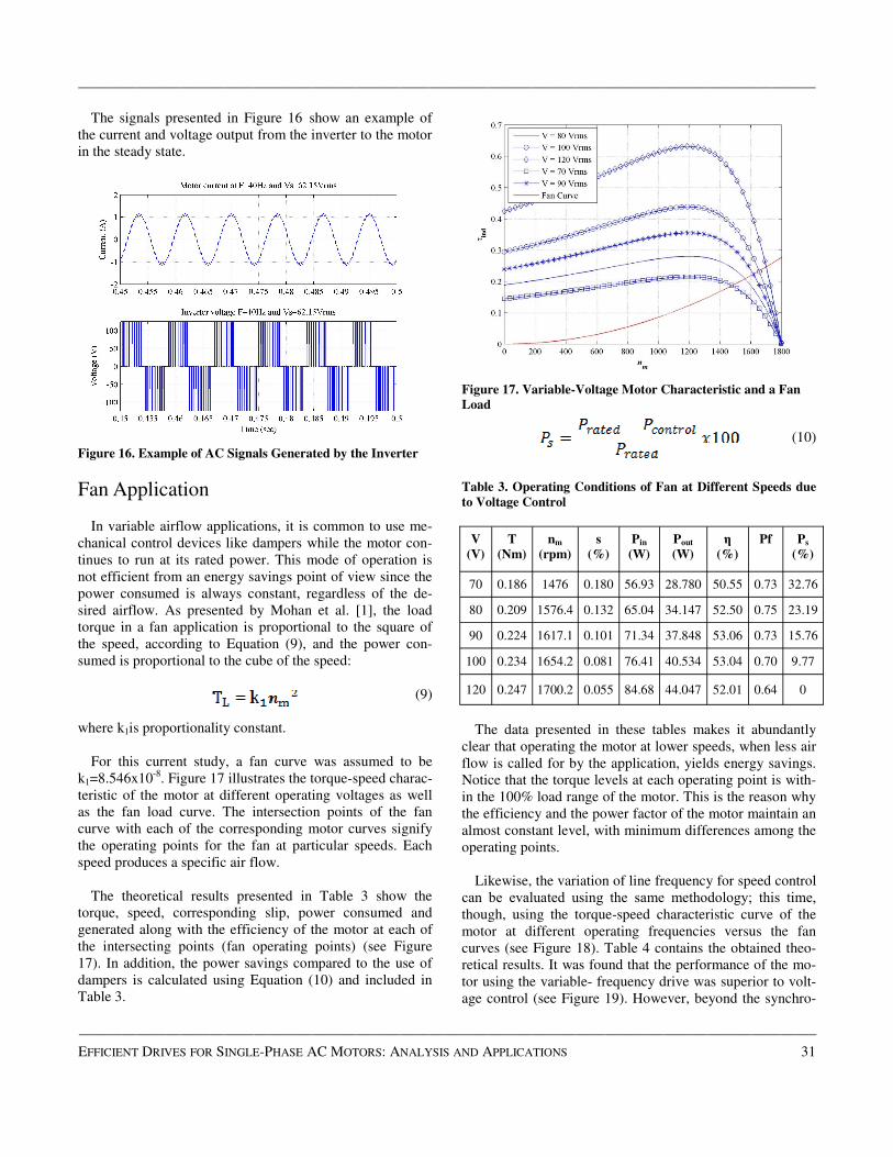
The signals presented in Figure 16 show an example of
the current and voltage output from the inverter to the motor
in the steady state.
Figure 16. Example of AC Signals Generated by the Inverter
Fan Application
In variable airflow applications, it is common to use me-
chanical control devices like dampers while the motor con-
tinues to run at its rated power. This mode of operation is
not efficient from an energy savings point of view since the
power consumed is always constant, regardless of the de-
sired airflow. As presented by Mohan et al. [1], the load
torque in a fan application is proportional to the square of
the speed, according to Equation (9), and the power con-
sumed is proportional to the cube of the speed:
(9)
where k1is proportionality constant.
For this current study, a fan curve was assumed to be
k1=8.546x10⁻⁸. Figure 17 illustrates the torque-speed charac-
teristic of the motor at different operating voltages as well
as the fan load curve. The intersection points of the fan
curve with each of the corresponding motor curves signify
the operating points for the fan at particular speeds. Each
speed produces a specific air flow.
The theoretical results presented in Table 3 show the
torque, speed, corresponding slip, power consumed and
generated along with the efficiency of the motor at each of
the intersecting points (fan operating points) (see Figure
17). In addition, the power savings compared to the use of
dampers is calculated using Equation (10) and included in
Table 3.
Figure 17. Variable-Voltage Motor Characteristic and a Fan
Load
(10)
Table 3. Operating Conditions of Fan at Different Speeds due
to Voltage Control
The data presented in these tables makes it abundantly
clear that operating the motor at lower speeds, when less air
flow is called for by the application, yields energy savings.
Notice that the torque levels at each operating point is with-
in the 100% load range of the motor. This is the reason why
the efficiency and the power factor of the motor maintain an
almost constant level, with minimum differences among the
operating points.
Likewise, the variation of line frequency for speed control
can be evaluated using the same methodology; this time,
though, using the torque-speed characteristic curve of the
motor at different operating frequencies versus the fan
curves (see Figure 18). Table 4 contains the obtained theo-
retical results. It was found that the performance of the mo-
tor using the variable- frequency drive was superior to volt-
age control (see Figure 19). However, beyond the synchro-
V
(V)
T
(Nm)
nm
(rpm)
s
(%)
Pin
(W)
Pout
(W)
η
(%)
Pf Ps
(%)
70 0.186 1476 0.180 56.93 28.780 50.55 0.73 32.76
80 0.209 1576.4 0.132 65.04 34.147 52.50 0.75 23.19
90 0.224 1617.1 0.101 71.34 37.848 53.06 0.73 15.76
100 0.234 1654.2 0.081 76.41 40.534 53.04 0.70 9.77
120 0.247 1700.2 0.055 84.68 44.047 52.01 0.64 0
——————————————————————————————————————————————————–
EFFICIENT DRIVES FOR SINGLE-PHASE AC MOTORS: ANALYSIS AND APPLICATIONS 31

——————————————————————————————————————————————–————
——————————————————————————————————————————————–————
32 INTERNATIONAL JOURNAL OF MODERN ENGINEERING | VOLUME 13, NUMBER 2, SPRING/SUMMER 2013
nous speed, the motor consumes more power and, therefore,
the power savings are negative (see Table 4).
Figure 18. Variable-Frequency Motor Characteristic and a
Fan Load
Table 4. Operating Conditions of Fan at Different Speeds due
to Frequency Control
Figure 19. Power Savings Comparison: Voltage Control and
Frequency Control
It is important to emphasize that the mathematical model
presented here does not include the effects of harmonics.
When the motor is operated using the variable-frequency
drive, some harmonics are present in the voltage and current
signals. The result of this is the mismatch in the power con-
sumption of the motor at rated values (120V, 60Hz) for the
two cases presented in Tables 3 and 4. However, it was also
noticed that the calculated power factor using the mathemat-
ical model, and the one found through simulations, was the
same. Therefore, the mismatch on power consumption was
due to a lower current present in the motor.
Conclusion
The SPIM was successfully modeled for its steady-state
operation in using the equivalent circuit method and experi-
mentally determining the motor parameters. Test methodol-
ogies were developed and utilized to further validate the
model and utilize it as an assessment tool for the efficiency
of control schemes.
Three different speed-control schemes were considered
when studying the performance of the motor under different
loading conditions. It became evident that the high THD
produced by the phase controller had a significant negative
impact on motor performance, due to excessive power loss-
es. Moreover, using the steady-state model, the full-bridge
inverter was simulated as a variable-frequency drive and
compared to the phase and voltage control schemes. It was
found that the efficiency of the overall system was im-
proved by approximately 25% at high loading conditions.
However, at low loading conditions, the three techniques
yielded a low efficiency of about 30%. It became clear that
operating conditions may require changing the control
scheme.
It is worth emphasizing that while PWM methodologies
are usually embedded in numerous motor drives for their
positive impact on the efficiency of the drives, the overall
control scheme still needs to be evaluated carefully for its
overall efficiency.
The fan application was studied for voltage control and
variable-frequency control. These two schemes were chosen
because of their higher efficiency compared to phase con-
trol. The variable-frequency drive yielded better results
from an energy efficiency point of view. In addition, it is
important to note that the variable-frequency drive works
for a wider range of speeds, resulting in more versatility for
the fan application. Thus, in some applications it might be
necessary to have several options for the airflow and a wid-
er range of speed would be needed. However, very high
speeds may require changing the control scheme.
f
(Hz)
V
(V)
T
(Nm)
nm
(rpm)
s
(%)
Pin
(W)
Pout
(W)
η
(%)
Pf Ps
(%)
40 80 0.114 1156 0.036 15.72 13.825 85 0.59 81
50 100 0.179 1445 0.036 37.7 27.012 64 0.70 55
60 120 0.247 1700 0.055 69.88 44.047 63 0.64 17
70 120 0.312 1911 0.090 101.3 62.443 62 0.70 -20
80 120 0.365 2065 0.139 116.1 78.813 68 0.76 -37

——————————————————————————————————————————————–————
References
[1] Mohan, N., Undeland, T., & Robbins, W. (1998).
Power Electronics: Converters, Applications, and
Design. New York: John Willey & Sons, Inc.
[2] Schneider Electric. Unlocking Energy Efficiency -
Management and Control is the Key. Retrieved from
http://www.schneider-electric.co.il/documents/
solutions/146-root-8-ee_white-paper.pd
[3] Latt, A. Z., & Win, N. N. (2009). Variable Speed
Drive of Single Phase Induction Motor Using Fre-
quency Control Method. Proceedings of Internation-
al Conference on Education Technology and Com-
puter ICETC , (pp. 30-34, 17-20).
[4] Ahmed, N., Amei, K., & Sakui, M., (2000). AC
chopper voltage controller-fed single-phase induction
motor employing symmetrical PWM control tech-
nique. Electric Power Systems Research, 55, 15-25.
[5] Yildirim, & Bilgic, M., (2008). PWM AC Chopper
Control of Single-Phase Induction Motor for Variable
-Speed Fan Application. Proceedings of Industrial
Electronics, IECON 34th Annual Conference of
IEEE, (pp. 1337-1342).
[6] Chapman, S. (2005). Electric Machinery Fundamen-
tals. New York: McGraw-Hill.
[7] Amin, B. (2002). Induction Motors: analysis and
torque control. New York: Springer.
[8] Sankaran, C. Effects of harmonics on Power Sys-
tems. EC&M Magazine. Retrieved from http://
ecmweb.com/mag/
electric_effects_harmonics_power_2
[9] Hamad, S. H., Bashi, S. M., Aris, I., & Mailah, N. F.
(2004). Speed Drive of Single-Phase Induction Mo-
tor. National Power & Energy Conference (PECon).
Proceedings, Kuala Lumpur, Malaysia, (pp. 121-125,
29-30).
[10] Li, H., & Curiac, R. (2010). Motor Efficiency, Effi-
ciency Tolerances and the Factors That Influence
Them. Petroleum and Chemical Industry Conference
(PCIC). Record of Conference Papers Industry Ap-
plications Society 57th Annual, (pp. 1-6, 20-22).
Biographies
JUAN GALLEGO-CALDERON is currently a Ph.D.
student at the DTU Wind Energy department, The Technical
University of Denmark. He received his MS degree
(Electrical Engineering, 2012) from California State Univer-
sity Fresno, CA. His present research interests are in elec-
tromechanical modeling, control systems, simulation of
dynamical systems, multi-body dynamics and power sys-
tems in wind energy. He can be reached at [email protected]
NAGY BENGIAMIN is a Professor of Electrical Engi-
neering at California State University Fresno, CA, MEngr
(Systems Engineering, 1976) from Carleton University, and
Ph.D. (Electrical Engineering, 1979) from The University of
Calgary, Canada. Dr. Bengiamin’s current interests are in
power systems, power electronics, and control systems. He
is a senior member of IEEE. He can be reached at
——————————————————————————————————————————————————–
EFFICIENT DRIVES FOR SINGLE-PHASE AC MOTORS: ANALYSIS AND APPLICATIONS 33