Embed Size (px)
Citation preview

1
Min Ni, Qing Su, Zongwu Tang, Jamil Kawa
Synopsys Inc.
ISPD 2010, SF, CA
Efficient Design Practices for
Thermal Management of TSV
based 3D IC System

2
• Introduction: TSV based 3D IC
• A Review of 3D IC Thermal Management
• 3D IC Thermal Evaluation
• Thermal Impact of TSV Arrays in Close
Proximity to Hotspots
• Thermal Effects of TSV as a Function of
TSV Density
• Summary & Conclusions
Outline

3
• Vertical Stacking (source: IMEC)
– Includes face-to-face, and face-to-back (with TSV)
stack.
• Lateral Interposer (source: Panasonic)
TSV based 3D IC – Two Configurations

4
3D (TSV) IC Design Flow
TSV Modeling
Synthesis &
DFT
Physical
Design
Parasitic
Extraction
• Thermo-mechanical
stress analysis
• Electrical variation
Physical
Verification
Stack
Sign-off
Stress & Reliability
Modeling
3D Stacked Device
• TSV connectivity
checking w/JTAG
• 1000x compression
• Multi-die bump &
TSV floorplan
• TSV P&R
• Extract TSV,
u-bump, backside
RDL metal
• TSV aware LVS/DRC
• TSV aware timing,
IR-Drop, EM
analysis
• Thermal analysis*
Physical
Design
TSV
Bumps
*application dependent
Mfg
.3
D I
C D
esig
n &
Verification

5
• Vertical stacking exacerbates thermal problem– Higher peak
temperature
– Risk of hotspot alignment
– Performance and reliability implications
• Thermal management needed early in design flow
Background
Die (Stack)
Partitioning
Synthesis &
DFT
Physical
Design
Extraction
•System level
design
exploration
• Logic
partitioning
• TSV
connectivity
checking
w/JTAG
• Test methods
• Multi-die bump
&
TSV floorplan
• Auto TSV P&R
• IC-Package I/F
• TSV aware
timing,
IR-Drop, EM
analysis
• Thermal
analysis
• TSV aware
physical
verification
EDA Design Methodology
Tim
ing
/Po
we
r A
na
lysis
• Extract TSV,
u-bump,
backside
RDL metal
Physical
Verification
Stack
Sign-off
TCAD
Thermal impact
On mechanical
characteristicsoverlappi
ng
hotspots
from
different
dies
-power
-thermal (run
away)
-electrical
Packaging
integrated
system
evaluatio
n

6
• Thermal vias & thermal TSVs– Pros
• can utilize existing vias and TSVs
• no additional processing steps needed
– Cons• non-scalable due to vertical heat path.
• area penalty for extra thermal TSVs
• Fluidic channels– pros
• scalable with chip area and number of tiers
– cons• design complexity
• Extra reliability
• needed vertical resources
Thermal Management Perspectives

7
• TSVs
– Signal TSVs
– PG TSVs
– Thermal TSVs
– Single uniform
diameters
TSVs

8
• Placement of TSVs– Use TSV array clusters to minimize area
penalty on silicon and interconnect
– Need to pay attention to mechanical structural balance in TSV placement
• Are dedicated thermal TSVs really needed?– Introduced at design planning stage?
• Academia papers on inserting extra TSVs suggests so
– hotspots are not necessarily known at this stage
– In post routing stage?• Hotspots are known
– Better assessment of need for extra TSVs
– Exploit metal density and PGS TSVs requirements
– proximity to hotspot planning
Thinking Loud
A single TSV and a TSV
array. Exclusion zone is
minimum space of TSV to
active devices- usually 5um

9
• Consider whole system vs. 1 die at a time– Eliminates artificial boundary conditions
– Eliminates need for large number of iterations• Smaller run time
• Used numerically based thermal simulator solving a ciruit-equivalent thermal network– heat source is analogous to a circuit’s current
source
– thermal resistance is analogous to electric resistance
– temperature gradient is analogous to electric potential (voltage) in circuits
Thermal Simulation Considerations
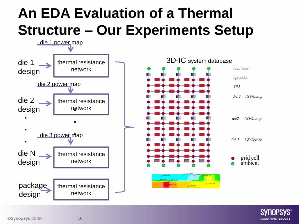
10
An EDA Evaluation of a Thermal
Structure – Our Experiments Setup
die 1
design
die N
design
.
.
.
die 2
design .
.
.
thermal resistance
network
die 1 power map
thermal resistance
network
thermal resistance
network
die 2 power map
die 3 power map
package
designthermal resistance
network
3D-IC system database

11
• R1 is the relative thermal resistivity between the heat source and ambient
• R2 is the relative thermal resistivity between the dissipation surface and ambient.
• R12 is the effective thermal resistivity between the hot spots and cold spots
Thermal circuit equivalence
R12V1 V2
R2
R1 Is -I d=-kV2
I12
Min. temperature near
dissipation surface
Max. temperature near
heat source

12
Setup
6x6 mm2
50um thin silicon substrate
Added “connectivity” to heat
sink makes thermal TSVs,
in experiment

13
;;;;;;;;;;;;;;;;;;;;;;;;;;;;;;;;;TIER {
TYPE = DIE ;NAME = die1COPY = nullDB_PATH =
/remote/atg5/mni/sandbox2/PrimeRail_TA_LabRDF = ta_cfg.rdfXCRD = 0YCRD = 0FLIP = NFLIPPOWER_RAMPUP = diea.prpDEBUG_PMAP = diea.mapDEBUG_THNET = diea.mtx
}
3D IC construction;;;;;;;;;;;;;;;;;;;;;;;;;;;;;;;;;;;TIER {
TYPE = BUMPNAME = die1_die2;dimension of the bump arrayXDIM = 10 YDIM = 10DIAMETER = 15PITCH = 20;thickness of the bump layer THICK = 30XCRD = 0YCRD = 0TCCU = 273TCOX = 66DEBUG_THNET = bump_diea_dieb.mtx
}
;;;;;;;;;;;;;;;;;;;;;;;;;;;;;;;;;;;;;;TIER {
TYPE = DIENAME = die2COPY = nullDB_PATH = /remote/atg5/mni/sandbox2/PR_TA_LabRDF = ta_cfg.rdfFLIP = XFLIPXCRD = 0 YCRD = 0POWER_RAMPUP = dieb.prpDEBUG_PMAP = dieb.mapDEBUG_THNET = dieb.mtx
}
;;;;;;;;;;;;;;;;;;;;;;;;;;;;;;;;;;TIER {
TYPE = TSVNAME = tsvLayerNARRAY = 2ARRAY {
THRGH = NOSTART = dieA
XDIM = 5YDIM = 5XCRD = 10YCRD = 20DIAMETER = 15PITCH = 20TCON = 273
}}

14
Thermal effects of TSVs in close proximity to hotspots
Die 1
Die 2
Top view
Before and after TSV array insertion

15
Impact of signal/power TSV
array on temperature of 3D IC
A single TSV and a TSV array.
Exclusion zone is minimum space of
TSV to active devices- usually 5um
with different size (one array for each of the 4 hot spots)
40
60
80
100
120
140
160
0 0.005 0.01 0.015 0.02 0.025 0.03
Tem
pe
ratu
re (°C)
TSV area as a ratio to die area (%)
MaxT
MinT
DeltaT The maximum temperature decreases as
TSVs are inserted, however, the effects
saturate quickly. The minimum
temperature does not drop.
The net effect of TSV insertion in 3D IC is
to reduce the peak temperature and the
temperature gradient.

16
40
45
50
55
60
65
70
0 0.01 0.02 0.03
Delt
a T
em
pe
ratu
re (°C)
TSV area as a ratio of die area (%)
SP TSVs
Thermal TSV
The ability of reducing thermal
gradient is similar for both
signal/power TSV and thermal (direct
connection to sink)TSV arrays.
59
60
61
62
63
64
65
66
67
68
0 200 400 600 800 1000
Delt
a T
em
pe
ratu
re (°C)
distance from TSVs to hotspots (um)
single TSV
10x10 array
Relation between the distance from
TSVs to hotspots and the reduction of
temperature gradient.
TSV thermal effects as a function of TSV
density with different size (one array for each of the 4 hot spots)

17
• Signal and power TSV arrays are practically as efficient as thermal TSVs.
• The proximity of thermal TSV arrays to hot spots is more critical than array size. Also, for close proximity arrays size matters but benefits from increased array size saturates quickly.
• Better practice is to place TSVs in array format to minimize area penalty, close to hotspot to maximize heat conduction, with compliance to other mechanical and electrical constraints
• It is the boundary heat transfer coefficient that dictates the steady state temperature of chips, not the amount of TSVs
Summary