Embed Size (px)
Citation preview
1
•Innovativeconcealedskeleton casing
•Plug fanswith frequency converter as standard
•Intelligent Control Options
•Energy recovery Accessories
Efficient Design,
Long Life,
Simple Maintenance,
Advanced Features
To enable remote management
THE CASING
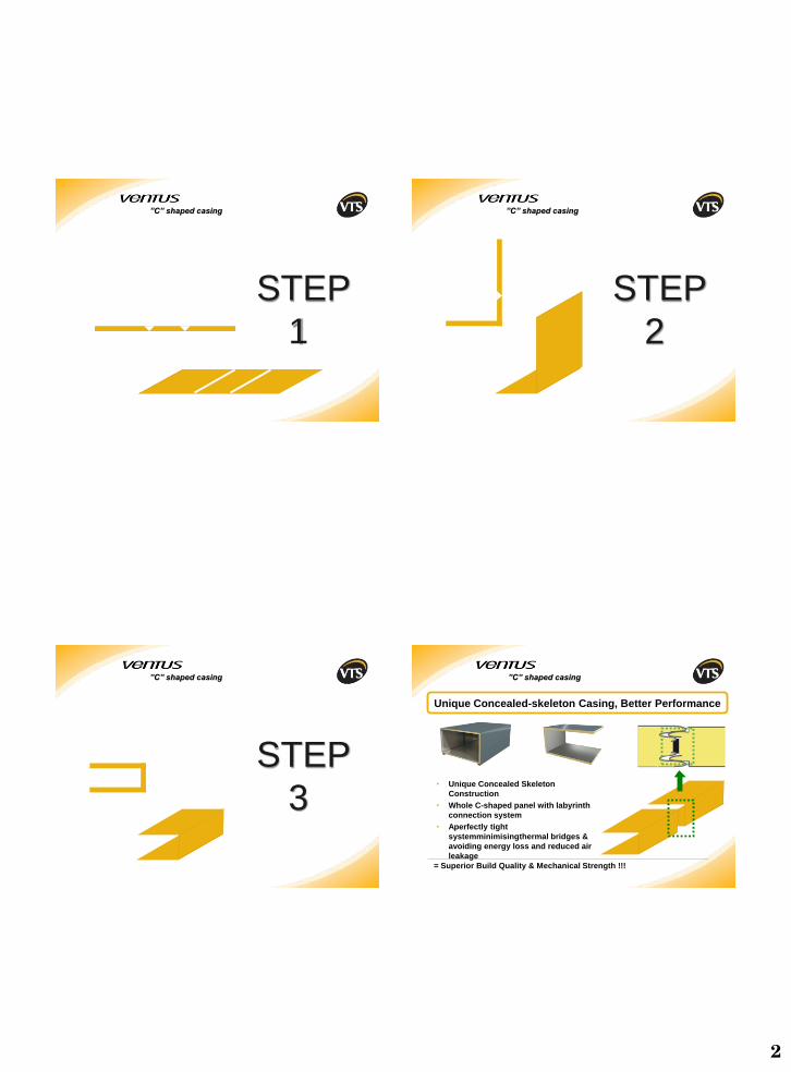
”C” shaped casing
STEP
0
2
STEP
1
”C” shaped casing
STEP
2
”C” shaped casing
STEP
3
”C” shaped casing
Unique Concealed-skeleton Casing, Better Performance
= Superior Build Quality & Mechanical Strength !!!
• Unique Concealed Skeleton
Construction
• Whole C-shaped panel with labyrinth
connection system
• Aperfectly tight
systemminimisingthermal bridges &
avoiding energy loss and reduced air
leakage
”C” shaped casing
3
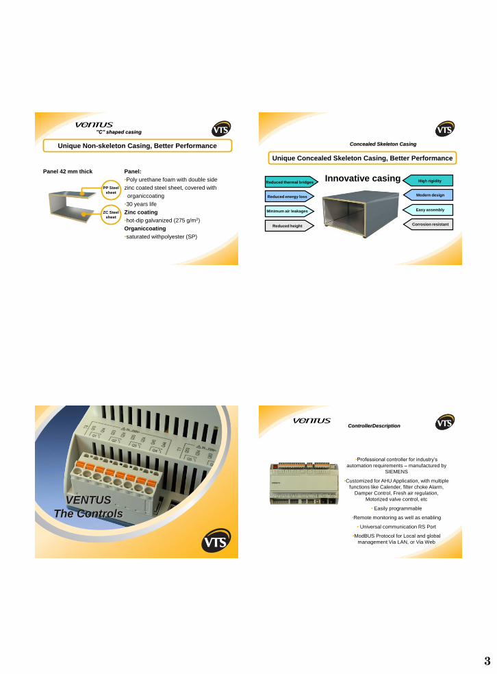
Unique Non-skeleton Casing, Better Performance
Panel:
•Poly urethane foam with double side
zinc coated steel sheet, covered with
organiccoating
•30 years life
Zinc coating
•hot-dip galvanized (275 g/m2)
Organiccoating
•saturated withpolyester (SP)
Panel 42 mm thick
ZC Steel
sheet
PP Steel
sheet
”C” shaped casing
Innovative casing
Unique Concealed Skeleton Casing, Better Performance
High rigidity
Modern design
Reduced thermal bridges
Reduced energy loss
Minimum air leakages Easy assembly
Reduced height Corrosion resistant
Concealed Skeleton Casing
VENTUS
The Controls
•Professional controller for industry’s
automation requirements – manufactured by
SIEMENS
•Customized for AHU Application, with multiple
functions like Calender, filter choke Alarm,
Damper Control, Fresh air regulation,
Motorized valve control, etc
• Easily programmable
•Remote monitoring as well as enabling
• Universal communication RS Port
•ModBUS Protocol for Local and global
management Via LAN, or Via Web
ControllerDescription
4
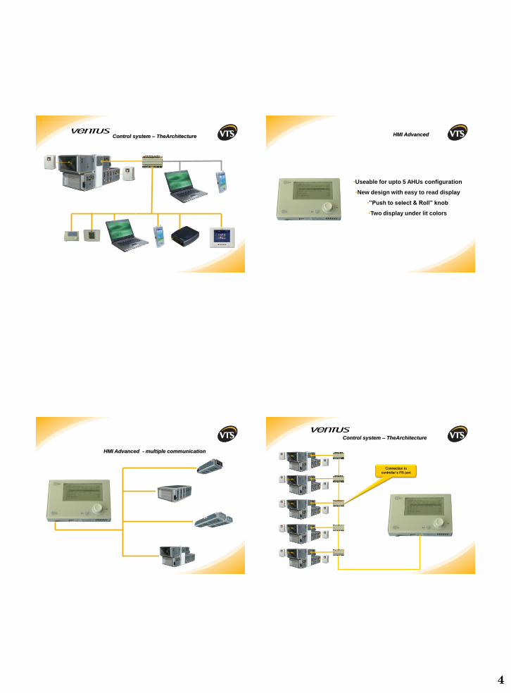
Control system – TheArchitecture
•Useable for upto 5 AHUs configuration
•New design with easy to read display
•”Push to select & Roll” knob
•Two display under lit colors
HMI Advanced
HMI Advanced - multiple communication
Control system – TheArchitecture
Connection to
controller’s PB port
5
Fan Performance
Optimization
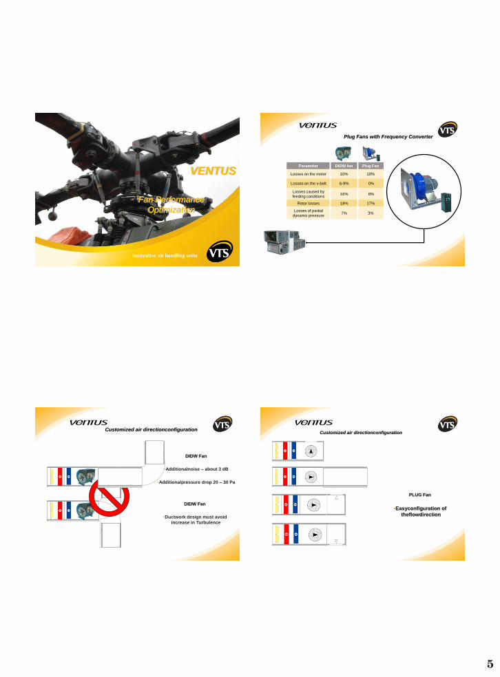
VENTUSParameter DIDW fan Plug Fan
Losses on the motor 10% 10%
Losses on the v-belt 6-9% 0%
Losses caused by
feeding conditions16% 8%
Rotor losses 18% 17%
Losses of partial
dynamic pressure7% 3%
Plug Fans with Frequency Converter
DIDW Fan
•Additionalnoise – about 3 dB
•Additionalpressure drop 20 – 30 Pa
DIDW Fan
•Ductwork design must avoid
increase in Turbulence
Customized air directionconfiguration
PLUG Fan
•Easyconfiguration of
theflowdirection
Customized air directionconfiguration
6
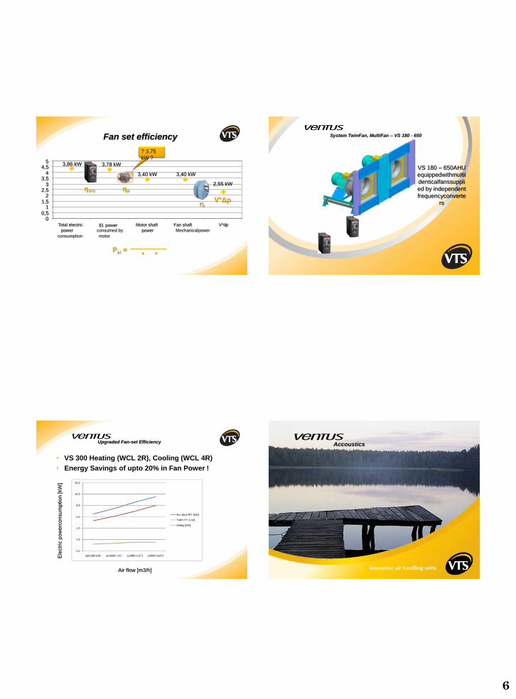
3,86 kW 3,78 kW
3,40 kW 3,40 kW
2,55 kW
00,5
11,5
22,5
33,5
44,5
5
V*dpFan shaft
Mechanicalpower
Motor shaft
powerEl. power
consumed by
motor
Total electric
power
consumption
Pel =* *
ηf
V*Δp
ηMηVFD
Fan set efficiency
? 3.75
kW ?
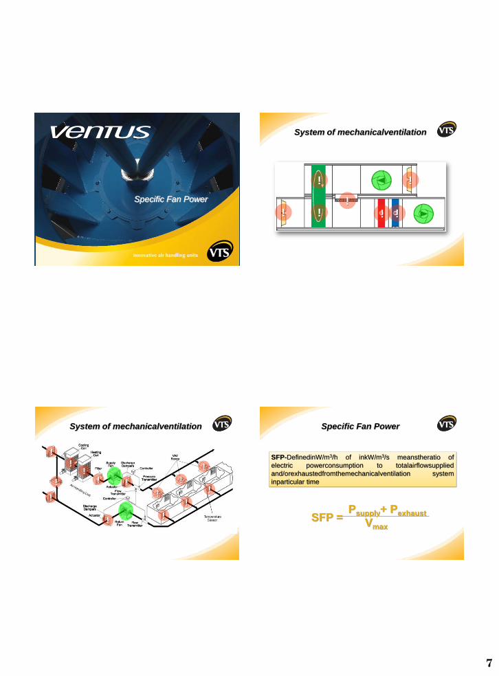
VS 180 – 650AHU
equippedwithmultii
denticalfanssuppli
ed by independent
frequencyconverte
rs
System TwinFan, MultiFan – VS 180 - 650
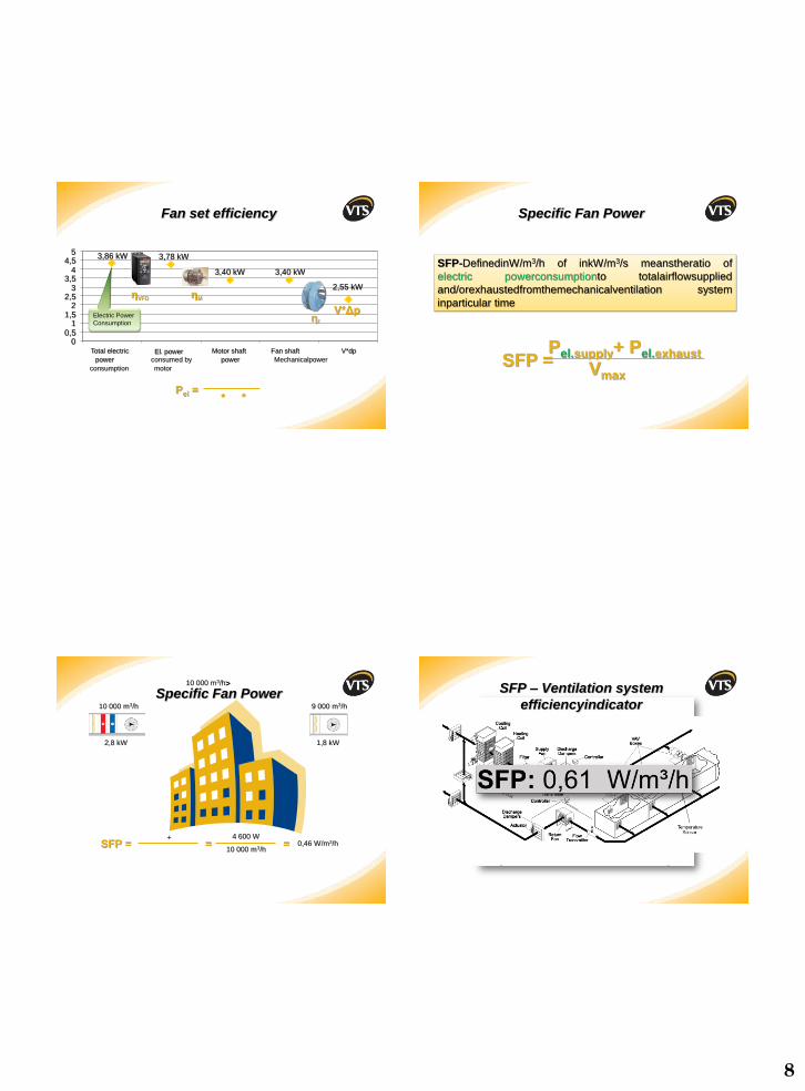
• VS 300 Heating (WCL 2R), Cooling (WCL 4R)
• Energy Savings of upto 20% in Fan Power !
Ele
ctr
ic p
ow
erc
on
su
mp
tio
n[k
W]
Air flow [m3/h]
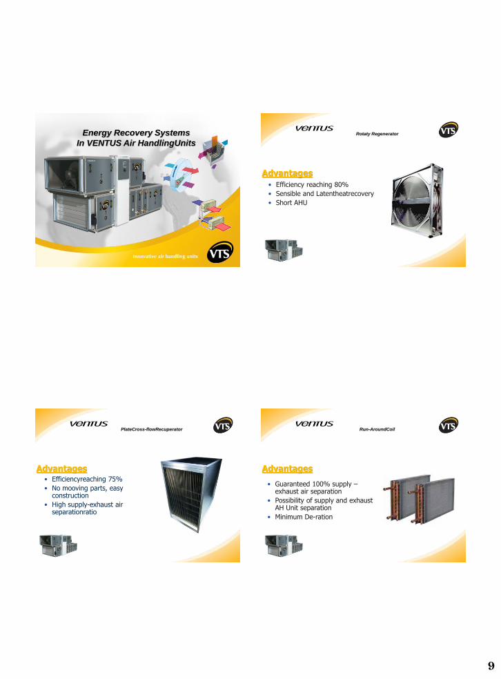
Upgraded Fan-set Efficiency Accoustics
7
Specific Fan Power
!
!
!
!
!!!
System of mechanicalventilation
!
!!
!
!
!
! !
!
!
!
!
!
!
System of mechanicalventilation
SFP =Psupply+ Pexhaust
Vmax
SFP-DefinedinW/m3/h of inkW/m3/s meanstheratio of
electric powerconsumption to totalairflowsupplied
and/orexhaustedfromthemechanicalventilation system
inparticular time
Specific Fan Power
8
3,86 kW 3,78 kW
3,40 kW 3,40 kW
2,55 kW
00,5
11,5
22,5
33,5
44,5
5
V*dpFan shaft
Mechanicalpower
Motor shaft
powerEl. power
consumed by
motor
Total electric
power
consumption
Pel =* *
ηf
V*Δp
ηMηVFD
Fan set efficiency
Electric Power
Consumption
SFP =Pel.supply+ Pel.exhaust
Vmax
SFP-DefinedinW/m3/h of inkW/m3/s meanstheratio of
electric powerconsumptionto totalairflowsupplied
and/orexhaustedfromthemechanicalventilation system
inparticular time
Specific Fan Power
10 000 m3/h 9 000 m3/h
2,8 kW 1,8 kW
>
SFP = =
10 000 m3/h
10 000 m3/h
4 600 W
= 0,46 W/m3/h
Specific Fan Power
+
SFP – Ventilation system
efficiencyindicator
9
Energy Recovery Systems
In VENTUS Air HandlingUnits
Advantages
• Efficiency reaching 80%
• Sensible and Latentheatrecovery
• Short AHU
Rotaty Regenerator
Advantages• Efficiencyreaching 75%
• No mooving parts, easyconstruction
• High supply-exhaust airseparationratio
PlateCross-flowRecuperator
• Guaranteed 100% supply –exhaust air separation
• Possibility of supply and exhaust AH Unit separation
• Minimum De-ration
Advantages
Run-AroundCoil
10
EN 13053 Standard
Ventilation for buildings. Air handling units. Rating and
performance for units, components and sections
• 7.2.8*: Fan location
– Installation of fans in Air Handling Units should be designed inway allowing maintenance of proper pressure conditions in orderto avoid leakages of contaminated air. This is especiallyimportant in case of systems in which migration of solid particlesor gases may occur in energy recovery section. (Leakages if any,should be into the Exhaust air, to avoid contamination)
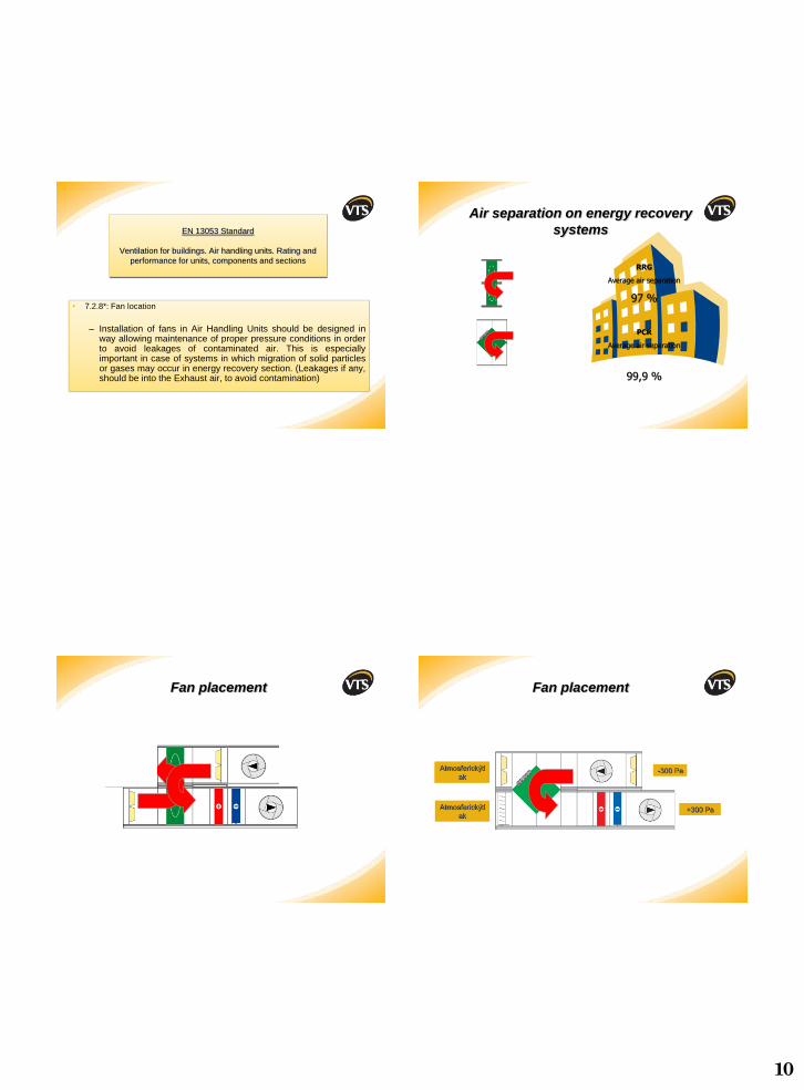
RRG
Average air separation
97 %
PCR
Average air separation
99,9 %
Air separation on energy recovery
systems
Fan placement
-300 Pa +300 Pa
Ciśnienie
atmosferyczne
Atmosferickýtl
ak
Atmosferickýtl
ak
-300 Pa
Fan placement
11
-300 Pa +300 Pa
Ciśnienie
atmosferyczne
Atmosferickýtl
ak
Atmosferickýtl
ak
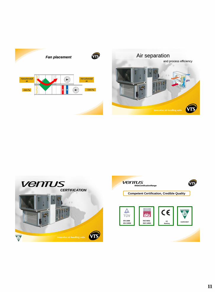
Fan placement Air separationand process efficiency
CERTIFICATION
ISO 9001
ISO 14001
EN 1886
EN 13053
CE
MarkingEUROVENT
Competent Certification, Credible Quality
WideCertificationRange
12
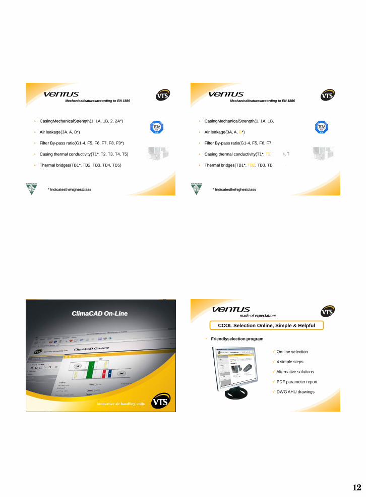
• CasingMechanicalStrength(1, 1A, 1B, 2, 2A*)
• Air leakage(3A, A, B*)
• Filter By-pass ratio(G1-4, F5, F6, F7, F8, F9*)
• Casing thermal conductivity(T1*, T2, T3, T4, T5)
• Thermal bridges(TB1*, TB2, TB3, TB4, TB5)
* Indicatesthehighestclass
Mechanicalfeaturesaccording to EN 1886
• CasingMechanicalStrength(1, 1A, 1B, 2, 2A*)
• Air leakage(3A, A, B*)
• Filter By-pass ratio(G1-4, F5, F6, F7, F8, F9*)
• Casing thermal conductivity(T1*, T2, T3, T4, T5)
• Thermal bridges(TB1*, TB2, TB3, TB4, TB5)
Mechanicalfeaturesaccording to EN 1886
* Indicatesthehighestclass
ClimaCAD On-Line
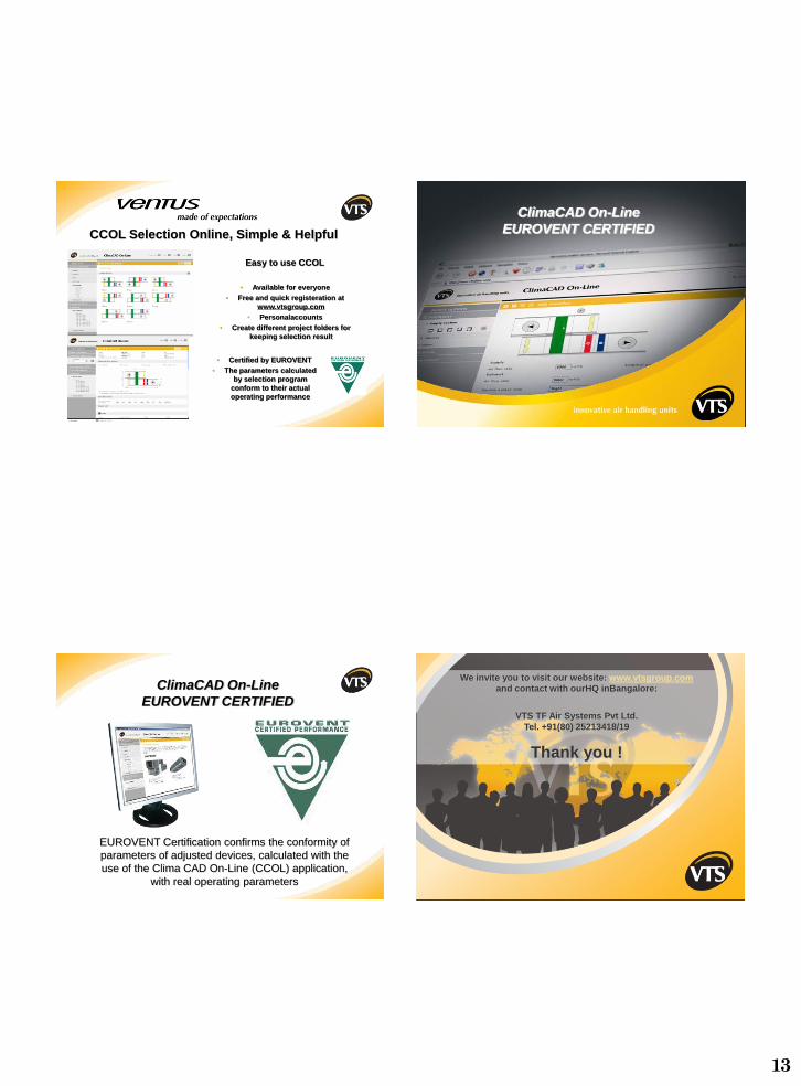
• Friendlyselection program
On-line selection
4 simple steps
Alternative solutions
PDF parameter report
DWG AHU drawings
CCOL Selection Online, Simple & Helpful
13
Easy to use CCOL
• Available for everyone
• Free and quick registeration at
www.vtsgroup.com
• Personalaccounts
• Create different project folders for
keeping selection result
CCOL Selection Online, Simple & Helpful
• Certified by EUROVENT
• The parameters calculated
by selection program
conform to their actual
operating performance
ClimaCAD On-Line
EUROVENT CERTIFIED
EUROVENT Certification confirms the conformity of
parameters of adjusted devices, calculated with the
use of the Clima CAD On-Line (CCOL) application,
with real operating parameters
ClimaCAD On-Line
EUROVENT CERTIFIED
We invite you to visit our website: www.vtsgroup.com
and contact with ourHQ inBangalore:
VTS TF Air Systems Pvt Ltd.
Tel. +91(80) 25213418/19
Thank you !