Embed Size (px)
Citation preview
-- \ -.
Ser I TH1 1
I N21d I I 1196 I $ National Research Conseil national I C . 2 1 Council Canada de recherches Canada 1 BIDG
B I B L I O T H ~ O F J Rcch. B 2 r " l ~ .
C N R C - I -
EFFICIENCY OF EXTENDED SURFACES WITH SIMULTANEOUS
HEAT AND MASS TRANSFER
by A.H. Elmahdy and R.C. Biggs
ANALYZED
Reprinted from ASHRAE Transactions, 1983 Vol. 89, Part 1A p. 135 - 143
UBR Paper No. 1 l9El Division of Building Research
Price $1.00 OTTAWA NRCC 23376

Ce document p r d s e n t e un a l g o r i t h m e en vue de d b f i n i r 1 'ef f i c a c i t d de su r f aces Btendues ( a i l e t t e s c i r c u l a i r e s ou long i tud ina l e s ayant une 6paisseur uniforme) lo rsque l e s t r a n s f e r t s thermique e t de masse s e produisent ~ i m u l t a n ~ e n t . La r d p a r t i t i o n de l a t empba tu re s u r l a su r f ace des a i l e t t e s est obtenue par l a r 'esolution d'une equat ion d i f f k e n t i e l l e non l i n g a i r e de second ordre.
L 'e f f icac i t ' e g loba le de la sur face humide d'une a i l e t t e est dgtermin'ee en u t i l i s a n t l es Bcarts de temp'erature e t les 6 c a r t s h y g r o d t r i q u e s p a r t i c u l i e r s ag i s san t co- moteurs du t r a n s f e r t thermique e t du t r a n s f e r t de masse reapectivement. La not ion d ' e f f i c a c i t d d'une a i l e t t e 3 su r f ace humide e s t semblable 3 l a dg f in i t i on fondamentaJa dl---,
Unique e t exac t , su r f ace de l ' a i l Bgalement s e r v i r refroidissement prgcises. i - - -. -
! l a peut 1 de f i n s

No. 2744
Efficiency of Extended Surfaces with Simultaneous Heat and Mass Transfer
A.H. Elmahdy R.C. Biggs ASHRA E Member
ABSTRACT
An algorithm is presented to determine the efficiency of extended surfaces (circular or longitudinal fins with a uniform thickness) when simultaneous heat and mass transfer occur. 'fhe temperature distribution over the fin surface is calculated by solving numerically a nonlinear, second-order differential equation.
The overall fin efficiency of a wet surface is evaluated using the temperature and specific hmidity differences as the driving forces for heat and mass transfer, respectively. The concept of efficiency of a wet surface fin is similar to the basic definition of a dry surface fin.
The presented algorithm is unique and accurate in determining the condition of the fin surface with regard to being dry or wet. This model could also be used to optimize the cooling and dehumidifying coil design for specific operating conditions.
INTRODUCTION
Air-to-water heat exchangers generally form the thermodynamic link between the water side (boilers and chillers) and the airside of heating, ventilating, and air-conditioning systems (HVAC) in buildings. thong the factors affecting the thermal performance of such heat exchangers are geometry and materials, air and water flow rates, and thermodynamic conditions. If latent heat transfer exists in cooling and dehumidifying coils, considerable change in the coil performance will occur as a result of the change in the extended surface efficiency.
Energy requirements for heattng and cooling of buildings can be calculated by means of energy anal sis computer programs, which simulate the performance of buildings and W A C component^.^-^ An accurate analytical representation of all components of the building's energy system is necessary, however, to predict the building's energy requirements with accuracy.
The variation of extended surface efficiency must be known to model cooling-coil performance.4~5 When phase change occurs (in dehumidification), the corresponding change in extended surface efficiency becomes an influential factor in determining coil performance under both full- and part-load condition^.^
This paper provides an analytical technique to be used in determining the efficiency of circular or continuous fins under conditions of simultaneous sensible and latent heat transfer. The concept of fin efficiency for dry fins is outlined and that for wet surface conditions determined using a similar approach.
DRY SURFACE FIN EFFICIENCY
In this section, fin efficiency, Q, is defined and the basic approach for determining it is outlined. The coil fin will be dry when its surface temperature is higher than the dew-point temperature of the air adjacent to it. The driving force for heat transfer is then the temperature difference between the fin surface and the air. In most cases t~le temperature at the base of the fin, tb, will be very close to the tube surface temperature. Owing to the thermal resistance of the fin material, there is a temperature gradient along the fin surface

I
from base to tip. Thus, the heat-transfer pot 'ntlal of the fin is reduced in comparison with that of a "perfect" fin of infinite thermal co 1 ductivity.
The inescapable loss in performance of the real fin is characterized as fin efficiency, n, defined as the ratio of actual heat transfer through a fin surface to the heat transfer of an ideal fin at tb.
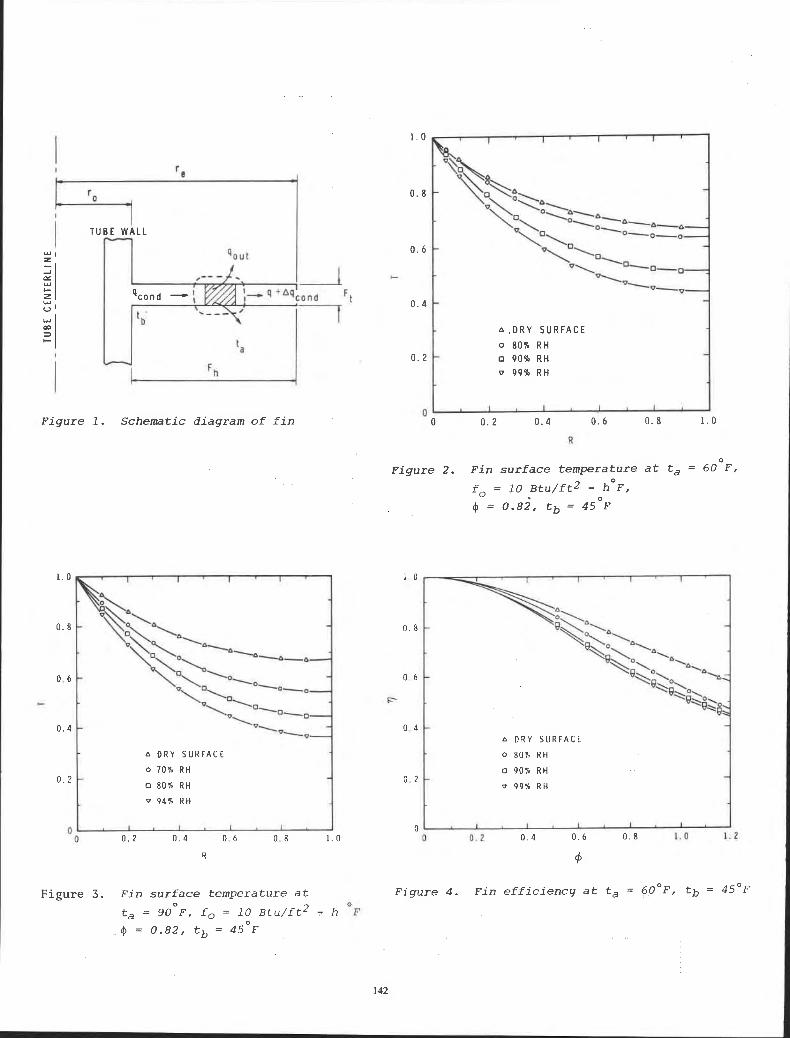
Consider the constant-thickness circular fin shown in Fig. 1. A heat balance on a circumferential control volume leads to the following differential equation:
where
Eq 1 can be solved to determine the temperature distribution over the fin surface using these boundary conditions:
and
Fin efficiency can be obtained using the basic definition and temperature distribution over the fin surface resulting from Eq 1.
The temperature distribution obtained by solving Eq 1 when substituted into Eq 2 gives the following expression for nd:7'10
Eq 3 shows that fin efficiency is a function of fin geometry, the film heat-transfer coefficient, fo, and fin material thermal conductivity, k, i.e.,
where - 4 is a nondimensional parameter defined as
WET SURFACE FIN EFFICIENCY
Condensation of moisture on the fin surface occurs whenever the fin temperature is below the dew-point temperature of the air adjacent to the surface. The difference between the fin surface temperature and the surrounding air temperature is the driving force for sensible heat transfer, whereas the difference between the specific humidity of saturated air at the fin surface temperature and that of the adjacent air is the potential for latent heat transfer.

Fin efficiency is considerably influenced by the presence of moisture and by the additional potential for heat transfer. Attempts have been made to determine TI using a modified form of the factor M. For example, the wet surface efficiency of a straight longitudinal fin was studied by ~cQuist0n.l l He assumed that the difference between the enthalpy of air adjacent to the fin and that of saturated air at the fin surface temperature is the potential for combined heat and mass transfer. By approximating the saturation curve on the psychrometric chart by a straight line over a small range of temperatures, the slope of the saturation line between two temperatures, tl and t2, may be expressed as
The author presented only an expression of n for a longitudinal fin of length L, perimeter P, and area A
tanh (MIL) 11 =
MIL
where
For a dry surface fin, bs is equal to zero and Eq 8 reduces to the conventional form given in the literature.
Ware and Hacha assumed12 that if the dry surface fin efficiency is expressed as
then the wet surface fin efficiency can be written in terms of the slope of the saturated air temperature enthalpy curve, m. at the mean fin surface temperature, as follows:
Previous attempts to evaluate nw failed to give an accurate expression based on the determination of the temperature distribution over the fin surface. As well, the complexity of the mathematical equations of various fin geometries has resulted in restricting the solution to longitudinal fins.
This paper presents a method of calculating the wet surface fin efficiency of a circular or a continuous fin of uniform thickness. Although the final results do not provide a closed form solution, they can easily be solved numerically with this technique.
Applying the first law of thermodynamics to the incremental area dAf (=2 nrdr) of a circular fin of uniform thickness, shown in Fig. 1,
Rewriting Eq 11 in terms of radius r and integrating over the entire fin surface yields
Le q = I 4r(fort + fmifg Wr) dr
0
, where
and
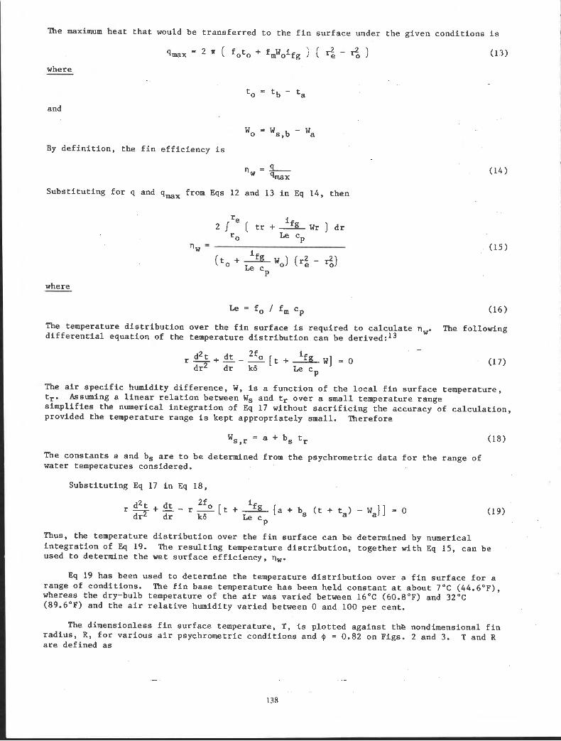
The maximum heat that would be transferred to the fin surface under the given conditions is
qmx = 2 n ( fOtO + fmWoifg 1 ( r$ - 6 ) (1 3
where - to = t b - ta
and
'0 's,b ' 'a
By definition, the fin efficiency is
Substituting for q and q-, from Eqs 12 and 13 in Eq 14, then
where
The temperature distribution over the fin surface is required to calculate nw. The following differential equation of the temperature distribution can be derived: l 3
The air specific humidity difference, W, is a function of the local fin surface temperature, tr. Assuming a linear relation between Ws and tr over a small temperature range simplifies the numerical integration of Eq 17 without sacrificing the accuracy of calculation, provided the temperature range is kept appropriately small. Therefore
The constants a and bs are to be determined from the psychrometric data for the range of water temperatures considered.
Substituting Eq 17 in Eq 18,
Thus, the temperature distribution over the fin surface can be determined by numerical integration of Eq 19. The resulting temperature distribution, together with Eq 15, can be used to determine the wet surface efficiency, nw.
Eq 19 has been used to determine the temperature distribution over a fin surface for a range of conditions. The fin base temperature has been held constant at about 7OC (44.6OF), whereas the dry-bulb temperature of the air was varied between 16OC (60.8"F) and 32°C (89.6"F) and the air relative humidity varied between 0 and 100 per cent.
The dimensionless fin surface temperature, T, is plotted .against the nondimensional fin radius, R, for various air psychrometric conditions and 4 = 0.82 on Figs. 2 and 3. T and R are defined as
and
Fin efficiency is plotted as a function of $t on Figs. 4 and 5 for various specific humidities. The average film heat-transfer coefficient for wet surface fins is calculated using the method described in Refs 13 and 14.
The method described in this paper can be used to calculate the fin efficiency of a wet surface fin of a circular or continuous flat plate type. A continuous plate fin can be considered to be composed of discrete circular fins having the same surface area. This approximation does not result in a serious error on the evaluation of fin efficiency.15916
Figs. 2 and 3 show that the temperature profiles of a wet surface fin lie below those of a dry surface fin. As the air relative humidity increases, the departure of the temperature profile from the dry surface curve becomes greater.
For a given set of conditions (4, fo, ta, and tb), the potential for heat and mass transfer increases as the air relative humidity increases. This results in an increase in the theoretical maximum heat transfer through the fin base, as expressed in Eq 13. The corresponding actual heat transfer through the fin surface, however, does not increase by the same amount, resulting in a decrease in fin efficiency. This is illustrated in Figs. 4 and 5 when plotting II vs 4.
The algorithm presented in this paper is a detailed and accurate model for determining the fin efficiency of a wet surface fin. It can be used to predict 0, for various fin geometries, different air psychrometric conditions, and fin base temperatures. Hence, an empirical formula of 11, could be developed as a function of all other variables using regression analysis techniques. This has been done successfully to predict heat exchanger performance.4 5 14
Another important result of this study is that coil designs could be optimized for specific operating conditions. The optimum fin length (radius) increases as the amount of dehumidification increases.
CONCLUSION
An algorithm to calculate the efficiency of a wet surface fin is presented for a circular or continuous flat plate fin with uniform thickness. This new approach, however, could be applied to other fin geometries.
The analytical results showed that a significant reduction in fin efficiency occurs with increasing amounts of dehumidification. The departure of fin efficiency from the dry surface condition depends on the difference between the specific humidity of the air surrounding the fin and air at fin base temperature.
The technique presented in this paper could be used to predict the performance of existing heat exchangers, and during the design stage to detennine the optimum fin area for dehumidification processes.
NOMENCLATURE
Symbol Description
a Constant in Eq 16
A Cross-section area of a straight fin
bs Slope of the saturation curve on the psychrometric chart
C P
Moist air specific heat at constant pressure
rn Average mass transfer coefficient
£0 Average film heat-transfer coefficient on the air side
if g Latent heat of evaporation of water
=o , I1 Modified Bessel functions of zero and first order, respectively
k Fin material thermal conductivity
KO, K1 Modified Bessel function of zero and first order, respectively
1 Straight fin length
Le Lewis number
m Slope of i - t saturation curve on the psychrometric chart
M Parameter defined by Eq 1
M1 Parameter defined by Eq 8
P Straight fin perimeter
4 Rate of heat transfer
R Dimensionless fin radius, Eq 21
r Fin radius measured from the tube centerline
re, r0 Outer and inner fin radius, respectively
T Dimensionless temperature, Eq 20
a Air dry-bulb temperature
tb Fin base temperature at r = ro
Fin surface temperature at radius r
'a Specific humidity of air
Ws ,r Specific humidity of saturated air at temperature tr
Units
kg, / kgair (lb , / lbair m2 (ft2)

's ,b Specific humidity of saturated air at temperature tb
'4 Function
@ Fin parameter defined by Eq 5
6 Fin thickness, m (ft)
nd, nw Dry and wet surface fin efficiency, respectively
REFERENCES
1. Reference Manual for Energy Systems Analysis Series (Public Works Canada, 1978).
2. BLAST, The Building Loads Analysis System Thermodynamics Program, U.S. Amy, Construction Engineering Research Lab., Champaign, IL, June 1979.
3. DOE-2, Building Energy Analysis Group, Energy and Environment Div., Lawrence Berkeley Lab., Berkeley, CA, Feb. 1979.
4. A.H. Elmahdy and G.P. Mitalas, "Fortram IV Program to Simulate Cooling and Dehumidifying Finned Tube Multi-Row Heat Exchangers," National Research Council of Canada, Div. of Building Research, Computer Program No. 43, 1977.
5. A.H. Elmahdy and G.P. Mitalas, "A Simple Model for Cooling and Dehumidification Coils for Use in Calculating Energy Requirements for Buildings ," ASHRAE Transactions 83: 2 (197?), p. 103.
6. A.H. Elmahdy and R.C. Biggs, "Performance Simulation of Multi-Row Dry (and/or Wet) Heat Exchanger," Proceedings of the 6th International Heat Transfer Conference, Toronto, Canada, Vol. 4 (August i978), pp. 327-332.
7. C.A. Gardner, "Efficiency of Extended Surfaces," ASME Transactions 67:8 (19451, p. 621.
8. R.W. Stewart, "The Absolute Thermal Conductivities of Iron and Copper," Philoso hical Transactions, Royal Society of London, England, Vol. 184, Series A ( 1 8 9 3 e
9. D.G. Rich, "The Efficiency and Thermal Resistance of Annular and Rectangular Fins" (paper presented at the Third International Heat Transfer Conference, Chicago, IL, 7 to 12 August 1966).
10. J.L. Threlkeld, Thermal Environmental Engineering, 2nd ed. (Englewood Cliffs, NJ:Prentice Hall, 1970).
11. F. McQuiston, "Fin Efficiency with Combined Heat and Mass Transfer," ASHRAE Transactions 81:l (1975), pp. 350-355.
12. C. Ware and T. Hacha, "Heat Transfer from Humid Air to Fin and Tube Extended Surface Cooling Coils" (ASME Paper No. 60-HT-17, 1960).
13. A.H. Elmahdy, "Analytical and Experimental Multi-Row Finned Tube Heat Exchanger Performance During Cooling and Dehumidification Processes" (P~.D. thesis, Carleton University, Ottawa, Canada, 1975).
14. A.H. Elmahdy and R.C. Biggs, "Finned Tube Heat Exchanger: Correlation of Dry Surface Heat Transfer Data," ASHRAE Transactions 85:2 (1979), pp. 762-273.
15. R. Myers, "The Effect of Dehumidification on the Air Side Heat Transfer Coefficient for a Finned Tube Coil" (M.Sc. thesis, Univ. of Minnesota, 1967).
16. D.G. Kern and A.D. Kraus, Extended Surface Heat Transfer (McGraw Hill Co., 1972).
ACKNOWLEDGEMENT
This paper is a contribution from the Division of Building Research, National Research Council Canada, and is published with the approval of the director of the division.
I T U B E W A L L n
Figure 1. Schematic diagram of fin
o DRY SURFACE
0 70% RH
80% RH
v 9 4 % R H
-
A , D R Y S U R F A C E
Figure 2. Fin surface temperature at t, = 60-F,
o DRY SURFACE
0 8 0 % RH
0 9 0 % RH
V 9 9 % RH
Figure 3. Fin surface temperature at Figure 4. Fin efficiency at t, = 6 0 ° ~ , tb = 4 5 ' ~
t, = ~ o O F , fo = 10 ~tu/ft* - h O F
4 = 0.82, tb = 45OF

a D R Y S U R F A C E
0 7 0 % R H
0 80% R H
v 9 4 % R H
0 0 Figure 5. Fin efficiency at t, = 90 F , tb = 45 F
This paper, while being distributed in reprint form by the Division of Building Research, remains the copyright of the original publisher. It should not be reproduced in whole or in part without the permission of the publisher.
A list of all publications available from the Division may be obtained by writing to the Publications Section, Division of Building Research, National Research Council of Canada, Ottawa, Ontario, KIA 0R6.
![b cHVAC&R Research - web.mit.eduweb.mit.edu/parmstr/Public/aaReprints/Papers/Variable-speed heat... · This article was downloaded by: [Massachusetts Institute of Technology], [Tea](https://img.pdfslide.us/doc/110x75/5a7fbe5d7f8b9a24668b9d0e/b-chvacr-research-webmit-heatthis-article-was-downloaded-by-massachusetts.jpg)