Embed Size (px)
Citation preview

Pilot Operated Safety Valves
Series 810 – Pop ActionSeries 820 – Modulate Action
High EfficiencyHigh Efficiency
The-Safety-Valve.com
CATALOG

22
No
No
No
No
No
Critical Service
Clean Service
Best Availability
Med
ium
-co
ntro
lled
Cha
nge-
over
val
ve
Bur
stin
g di
sc
Spr
ing
load
ed
Saf
ety
valv
es
High operating to set pressure ratio, high backpressure
or low total height?
Clean Service application?
Critical Service / highly corrosive application?
API specified application?
Additional components beyond safety valves
Steam, gas and liquid application with low capacity in relation
to valve size?
High Performance
API
Compact Performance
Modulate Action
Orifice ≥ F
Yes
Yes
Yes
Yes
Yes
Yes
Orifice ≤ F
Required Orifice letter?
Valve finderHow to find the right product group
High EfficiencyHigh Efficiency

33
Contents
Page
General
Valve Finder 2
Page
Options
Available options 60
Flange drillings • DIN EN 1092 61
Flange facings 62
Page
Product Description
Series 810 and 820 – General information 4
Series 810 and 820 – Specification at a glance 5
Good Reasons for the LESER Pilot Operated Safety Valve 6
Applications • Functional areas • Examples
89
Design Features 10
Seat Designs: API Standard and Extra Orifices 11
Application range soft seal disc and metal to metal at ambient temperature
12
Components 13
Operating Cycle 14
Series 810 – Pop Action • Operating Cycle 15
Series 820 – Modulate Action • Operating Cycle 16
Materials • Series 810, 820: Main Valve • Series 810: Pop Action Pilot Valve • Series 820: Modulate Action Pilot Valve • Series 810, 820: Manifold block
18202224
Article numbers • Type 811 WCB 1.0619 – Pop Action • Type 811 CF8M 1.4408 – Pop Action • Type 811 LCB – Pop Action • Type 821 WCB 1.0619 – Modulate Action • Type 821 CF8M 1.4408 – Modulate Action • Type 821 LCB – Modulate Action
262830323436
Page
Product Description
Pressure temperature ratings (ASME) 38
Dimensions and weights • Overview • Metric units – Semi nozzle • US units – Semi nozzle • Metric units – Full nozzle • US units – Full nozzle
3940424850
Screw dimensions • DIN EN 1092-1 Metric units • ASME B16.5 US units
52 56
Page
Product Description
Approvals - Series 810, 820 63
Spare parts kits • Type 811 Pop Action • Type 821 Modulate Action
6466
Pilot Operated Safety Valve Series 810 – Pop Action pilot valve Series 820 – Modulate Action pilot valve
44
High EfficiencyGeneral information
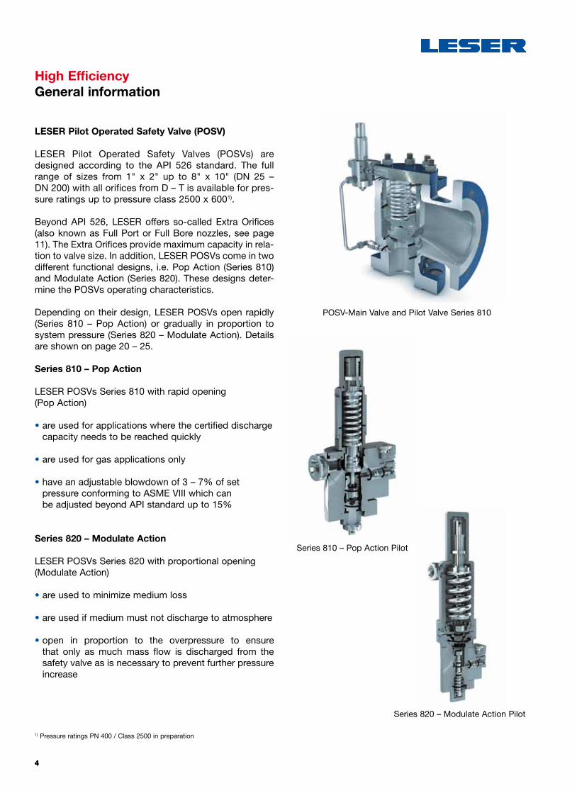
LESER Pilot Operated Safety Valve (POSV)
LESER Pilot Operated Safety Valves (POSVs) are designed according to the API 526 standard. The full range of sizes from 1" x 2" up to 8" x 10" (DN 25 – DN 200) with all orifices from D – T is available for pres-sure ratings up to pressure class 2500 x 6001).
Beyond API 526, LESER offers so-called Extra Orifices (also known as Full Port or Full Bore nozzles, see page 11). The Extra Orifices provide maximum capacity in rela-tion to valve size. In addition, LESER POSVs come in two different functional designs, i.e. Pop Action (Series 810) and Modulate Action (Series 820). These designs deter-mine the POSVs operating characteristics.
Depending on their design, LESER POSVs open rapidly (Series 810 – Pop Action) or gradually in proportion to system pressure (Series 820 – Modulate Action). Details are shown on page 20 – 25.
Series 810 – Pop Action
LESER POSVs Series 810 with rapid opening (Pop Action)
• are used for applications where the certified discharge capacity needs to be reached quickly
• are used for gas applications only
• have an adjustable blowdown of 3 – 7% of set pressure conforming to ASME VIII which can be adjusted beyond API standard up to 15%
Series 820 – Modulate Action
LESER POSVs Series 820 with proportional opening (Modulate Action)
• are used to minimize medium loss
• are used if medium must not discharge to atmosphere
• open in proportion to the overpressure to ensure that only as much mass flow is discharged from the safety valve as is necessary to prevent further pressure increase
POSV-Main Valve and Pilot Valve Series 810
Series 810 – Pop Action Pilot
Series 820 – Modulate Action Pilot
1) Pressure ratings PN 400 / Class 2500 in preparation

55
High EfficiencySpecification at a glance
The LESER Pilot Operated Safety Valve (POSV) comprises the POSV main valve and a pilot valve based on either the Pop Action (Series 810) or the Modulate Action (Series 820) designs. The table below shows their common and their specific features.
1) The possible flange pressure ratings depend on the size of the valve. Refer to page 61 to verify the correct option codes and availability of DIN EN flange ratings. For JIS see page 75 Extended Catalog.
2) Pressure ratings PN 400 / Class 2500 in preparation3) Set pressures > 256 bar (ASME) / 250 bar (DIN EN)
> 3705 psig (ASME) / 3625 psig (DIN EN) in preparation4) Temperatures outside -45 °C … + 200 °C / -49 °F … + 392 °F in preparation
LESER Pilot Operated Safety Valve (Main Valve and Pilot Valve)Common features for Series 810 and 820
Flange pressure rating1)acc. to ASME B16.5 CL150 – CL 25002)
acc. to DIN EN 1092-1 PN 10 – PN 4002)
Materialsacc. to ASME B16.5 WCB, LCB, CF8M
acc. to DIN EN 1092-1 1.0619, 1.4408
Pressure range acc. to ASME B16.5 36 – 6170 psig3)
acc. to DIN EN 1092-1 2.5 – 426 bar3)
Sizeacc. to ASME B16.5 1" to 8"
acc. to DIN EN 1092-1 DN 25 – DN 200
Temperatureacc. to ASME B16.5 -54 °F – 500 °F4)
acc. to DIN EN 1092-1 -48 °C – 260 °C4)
Orifice systemAPI Standard Orifice 1 D 2 – 8 T 10
Extra Orifice 1 G 2 – 8 T+ 10
Specific features of Series 810 and Series 820Series 810 820
Type 811 821
Pilot action type Pop Action Modulate Action
Full Open (overpressure) 1% max. 10%
Blowdown3 to 7% adjustable
(adjustable also beyond API standard from 3 up to 15%)
max. 7% fixed
Application Gas Steam, gases and liquids

66
High EfficiencyGood Reasons for the LESER Pilot Operated Safety Valve
Pilot operated safety valves have been a proven tech-nology for many decades especially in ASME oriented regions. However, some of the older designs show potential for improvement in areas like external tubing, capacity and delivery times. Based on customer feed -back and extended research and using Computational
Fluid Dynamics (CFD), Rapid Prototyping and one of the most modern factories for safety valves, LESER has developed the latest POSV on the market. The new LESER POSV offers unique benefits for both users and assemblers /maintenance personnel that are listed below.
Feature Benefit for user Benefit for assembler / maintenance
Design
Tubing between pilot valve and main valve integrated into top plate
• Less risk of damage to tubing
• Resistant against vibration
• No freezing
• Less tubing for easy removal of top plate
• Tubing between inlet and pilot remains accessible for easy cleaning
Backflow preventer integrated into manifold block as a standard component
• Easy ordering, no extra cost
• Less risk of damage to backflow preventer
• No need for machining to retrofit backflow preventer
Integral cast support brackets
• Compensation of reactive forces (high pressures)
• Easy handling during installation
Pilot valve manufactured completely from stainless steel
Less corrosion for higher operation reliability
NACE conversion only requires exchange of spring
All medium-wetted parts in tubing and pilot valve are either stainless steel or nickel-coated
Corrosion resistance

77
Feature Benefit for user Benefit for assembler / maintenance
High capacity / small size
EXTRA ORIFICE
Higher capacity for same valve size with Extra Orifice types. For details see page 11
Smaller valve sizes possible Small footprint in system
-20
%
OthersLESER POSV
20% less space requirement than typical competitive designs
Space-saving system designs possible
Small footprint in system
Modular system
Pop Action and ModulateAction pilot valves can beexchanged without tubingmodification
Easy later upgrade Less spare parts stock required. Easy conversion between Pop Action and Modulate Action pilot valve
LESER service
Sizing with VALVESTAR Comprehensive documenta-tion in multiple languages
4 weeks
delivery time
Four weeks delivery ex works for most types
Quick availability
Consistently high manufacturing quality
VALVESTAR®

88
High EfficiencyApplications – Functional areas
Across applications, there are four main functional requirements covered by the LESER Pilot Operated Safety Valve (POSV).
High Back Pressure Applications
• LESER POSVs can be operated in applications with a back pressure ratio (i.e. a ratio of back pressure / set pressure) of up to 70%. Spring loaded safety valves can be typically used up to 50% of back pressure.
• The absolute maximum back pressure is determined by the pressure class of the main valve outlet. Typically, LESER POSVs can be used for much higher back pressures than spring loaded safety valves.
Applications Requiring Set Pressure Independence of Back Pressure
The LESER POSVs open and operate independently of back pressure (within back pressure operating limits, see previous). The set pressure of the POSV is not affected by back pressure of any kind, i.e. superimposed, con-stant or variable.
Applications with High Inlet Pressure Losses (above 3%)
In these applications, POSVs with remote sensing should be utilized (refer to API 520 Part 2).
Applications with Increased Tightness Requirements
Since closing forces increase when approaching set pressure, LESER POSVs are particularly suitable for applications with high tightness requirements. Tightness is ensured up to 97% of set pressure because the closing forces increase approaching set pressure. Together with the defined blowdown, this allows operating the sytem close to the set pressure of the valve.
In a POSV, the system pressure acts on the main valve piston trying to push it open. It is, however, opposed by the same pressure because system pressure is also re-directed to the dome area above the piston.
Since the area of the piston exposed to pressure is larger in the dome than on the system side, this creates a greater net closing force on the main valve disc / nozzle. Approaching set pressure, closing forces increase. Comparison see page 10 Extended Catalog.

99
High EfficiencyApplications – Examples
Compressors in Gas Main Systems Pressure relief devices in these applications must allow for high operating pressures in relation to set pressure, which are required for efficient gas transport. Additionally, compressor vibrations put through requirements on the tightness of the safety valve.
LESER Series 810 and 820 POSVs offer an ideal solution for these conditions because:
• they enable highest possible operating pressure to set pressure ratios facilitating maximum energy density of transport medium
• they are not susceptible to leakage caused by com-pressor vibration as are spring loaded safety valves
Downstream Oil and Gas Industry Long pipings to the flare systems and common blow-down are frequently used in refineries. Both conditions lead to high back pressure of 50% of set pressure or more.
LESER Series 810 and 820 POSVs are used in these applications because:
• they offer high back pressure to set pressure ratios• they operate reliably independent of back pressure
Upstream Oil and Gas Industry Offshore platforms have especially high tightness require-ments to avoid leakage. Furthermore, the weight and size of the safety valves should be minimized due to space limitations on the platform.
LESER Series 810 and 820 POSVs are ideal for the up -stream oil and gas industry because of:
• their high tightness up to set pressure• their bonnetless design which allows lower weight and
lower valve height
Pumps in All IndustriesSystems with positive displacement pumps are protect-ed by safety valves. The medium is often discharged to the suction side of the pump which creates back pres-sure.
LESER Series 810 and 820 POSVs are used because:• they operate independently of back pressure• they allow high back pressure to set pressure ratios
Because of their suitability for high back pressure and high tightness applications, LESER Pilot Operated Safety Valves (POSVs) are used in a number of industrial areas including the following:

1010
High EfficiencyDesign Features
The following sections discuss the specific design and functional features of LESER's Pilot Operated Safety Valves (POSV) Series 810 und 820 which enable their application benefits. These benefits include:
• API 526 design ensuring standard valve sizes, dimen-sions and capacities for easy exchangeability in plants designed according to API standards
• API 526 product range with valve sizes from 1" to 8", orifice D to T, and pressure ratings up to Class 2500
• Additional Extra Orifices allowing to use a smaller valve size for a given orifice letter or capacity
• Flange connections according to ASME, EN and JIS available, which guarantee worldwide suitability
• Tubing between main valve and pilot valve integrated into top plate
• One design and spring (single trim) for gas and liquid applications reduces the number of spare parts and ensures low cost maintenance
• Body materials WCB, CF8M, LCB, 1.069, 1.4408 available from stock. Further materials on request.
• Back pressure independent design allows back pres-sure up to 70% of set pressure in most applications
• Metal discs or o-ring discs for a wide spectrum of applications
• NACE compliant materials enable NACE applications with minimal need for parts exchange as well as short delivery times
• Backflow preventer included as a standard feature – for details see page 18 Extended Catalog
• Easy-to-repair “top loader” design. This means the valve seat is a single part and can be installed from the top without the need to remove the entire POSV from the plant
In addition, the Series 820 – Modulate Action POSV is available in a diaphragm or piston design depending on the operating pressure range. For details on these designs, see “Diaphragm or Piston Design” in the section on the Series 820 – Modulate Action POSV see page 22.
Pilot Operated Safety Valve Pilot Operated Safety Valve for high pressures

1111
High EfficiencySeat Designs: API Standard Orifices and Extra Orifices
API Standard Orifice
Extra Orifice
The main valve of the LESER POSV Series 810 and 820 comes in a variety of orifices. These orifices are obtained by varying the diameter of the main valve nozzle (see illustrations below). For each nominal valve size, LESER offers several orifices which are in accordance with the API orifice system. These are termed API Standard Orifices. In
addition, for each nominal valve size a full bore nozzle is also available where the orifice is beyond the API orifice system. LESER refers to this orifice as an Extra Orifice. With an Extra Orifice, the customer often has the choice to use a smaller valve size for a required orifice and capacity (for details see page 82 Extended Catalog).
In the POSV, nominal valve sizes correspond to standard API and Extra Orifices as shown in the following table. Extra Orifice letters followed by a plus (+) sign, e.g. “K+”, mean that these valves offer a minimum of 25% more capacity than specified in API 526. For capacity values for Standard and Extra Orifices see the capacity tables on page 82 Extended Catalog.
Below are the details of the different nozzle designs for API Standard and Extra Orifices:
The API Standard Orifice ensures that the safety valve is in accordance with the API 526 orifice system.
The maximum drilling of the main valve seat (full bore) allows to discharge the maximum capacity in relation to the nominal valve size.
Full bore safety valves meet the API 526 except for their orifice, so their orifice is identified by a Extra Orifice letter.
DNI+O 25 x 50 40 x 50 40 x 80 50 x 80 80 x 100 100 x 150 150 x 200 200 x 250
Valve size 1" x 2" 11/2" x 2" 11/2" x 3" 2" x 3" 3" x 4" 4" x 6" 6" x 8" 8" x 10"
API Standard Orifice acc.
to API 526D E F D E F G G H G H J J K L L M N P Q R T
Extra Orifice G H J K+ N+ P+ R+ T+
API Standard Orifice
Extra Orifice

1212
Application rangeDN I+O 25 x 50 40 x 50 40 x 80 50 x 80
Valve size 1" x 2" 11/2" x 2" 11/2" x 3" 2" x 3"
API Standard Orifice acc. to API 526
D E F D E F G H G H J
Extra Orifice G H J K+
Set pressure
p [bar] [psig]
from 2.5 36
to 19.7 286
to 27.6 387
to 41.3 599
to 102 1480
to 256 3705
For soft seal material options, please refer to page 69 Extended Catalog.The chart above refers to ambient temperature conditions. For sealing materials at other temperatures, please ask LESER.
Metal to metal disc
Different sealing designs are used for different pressure ranges to ensure maximum tightness. Generally, at lower pressures, soft sealings are used, at higher pressures
metal-to-metal sealings are used. The following chart shows which sealing is used as a standard.
Soft seal disc
High EfficiencyApplication range of soft seal disc and metal to metal disc at ambient temperature
Application rangeDN I+O 80 x 100 100 x 150 150 x 200 200 x 250
Valve size 3" x 4" 4" x 6" 6" x 8" 8" x 10"
API Standard Orifice acc. to API 526
J K L L M N P Q R T
Extra Orifice N+ P+ R+ T+
Set pressure
p [bar] [psig]
from 2.5 36
to 19.7 286
to 27.6 387
to 41.3 599
to 102 1480
to 256 3705
Soft seal disc
Metal to metal disc

1313
The LESER Pilot Operated Safety Valve (POSV) consists of four main components in its standard configuration:
• the main valve, which serves to protect the pressurized equipment
• the pilot valve, which controls the opening and closing of the main valve
• the tubing is identical for both POSV Series, i.e. 810 and 820
• the manifold block with integrated backflow preventer (standard feature)
The backflow preventer prevents an unwanted open-ing of the main valve, which would cause backflow of medium from the outlet into the protected system. This problem can occur when there is back pressure that exceeds the inlet pressure (or insufficient pressure at the inlet), resulting in a net force acting on the valve piston in the opening direction, such as e.g. in a process running under vacuum.
Backflow Preventer – Included in standard configuration
POSV – Main valve, pilot valve, tubing and manifold block
Manifold block
Pilot valve
Tubing
Main valve
High EfficiencyComponents

1414
1.
2.
3.
4.
High EfficiencyOperating Cycle
LESER Pilot Operated Safety Valve (POSV) is controlled by process medium. To achieve this, the system pressure is applied to the pilot valve (= control component for the main valve) via the pressure pickup. The pilot valve then uses the dome above the main valve piston to control the opening and closing of the main valve.
While there are specific differences between the Series 810 – Pop Action POSV and the Series 820 – Modulate Action POSV, the basic operation of a LESER POSV can be described as follows. During operation, the POSV goes through these basic operating states:
1. Below set pressure: normal operationDuring normal operation, the system pressure is picked up at the main valve inlet and routed to the dome. Since the dome area is larger than the area of the main valve seat, the closing force is greater than the opening force. This keeps the main valve tightly closed.
2. At set pressure: actuating state At set pressure, the pilot valve actuates. The medium is no longer routed to the dome. This prevents a further rise in dome pressure. Also, the dome is vented. As a result, the closing force ceases as a pre-condition for the sys-tem overpressure to push the main valve open.
3. Main valve openingThe main valve opens. Depending on the design of the pilot valve, this opening is either rapid and complete (Pop Action) or gradual and partial following system pressure (Modulate Action).
4. At closing pressure: refilling the domeIf system pressure drops to closing pressure, the pilot valve actuates and again routes the medium to the dome. The pressure in the dome builds up and the main valve recloses either rapid and complete (Pop Action) or gradual and partial following system pressure (Modulate Action).
Operating states of the POSV

1515
1 2
4 3
1
2 3
4
High EfficiencySeries 810 – Pop Action Operating Cycle
1. Below set pressure: normal operation – feeding seat open, exhaust seat closed
When the main valve is closed the Pop Action Pilot is in a static state. During the filling process and with opened filling seat the medium is channeled via the manifold block into the dome of the main valve. In normal opera-tional state medium does not flow. The closing force of the spring acts on the relief seat and is bigger than the acting medium opening force.
2. At set pressure: feeding seat opening, exhaust seat closing
When set pressure is reached, the pilot valve opens the exhaust seat and closes the feeding seat. This releases the dome pressure. The release of dome pressure is a pre-condition for the opening of the main valve by system pressure.
3. At and above set pressure (+ max. 1%): pop openingAt set pressure, the main valve opens abruptly and completely feeding seat closed, exhaust seat open (Pop Action) (see bottom chart). The medium is channeled from the dome to atmosphere (see illustration on right).
4. At closing pressure: feeding seat open, exhaust seat closed
When the system pressure drops to closing pressure, the pilot valve actuates and again channels the system pressure to the dome of the main valve. Here, the sys-tem pressure builds up, the main valve recloses. The closing stage (blowdown) can be adjusted from at least 3% (when pressure loss at the inlet is low) to max. 15% blowdown difference.
Opening Characteristic with Overpressure and Blowdown Difference: Series 810 Pop Action
Set pressure Pressure
Lift
1 – Below set pressure: normal operation2 – At set pressure3 – Pop opening4 – At closing pressure – blowdown
Operating states Series 810

1616
1
2
High EfficiencySeries 820 – Modulate Action Operating Cycle
1. Below set pressure: normal operation – feeding seat open, exhaust seat closed
The system pressure is routed to the dome, keeping the main valve tightly closed (see illustration).
1a. Near set pressure: feeding seat closed, exhaust seat closed (not shown)
Shortly before set pressure is reached, the pilot valve closes the dome feeding seat. This keeps the dome pres-sure stable. A stable dome volume is the pre-condition which allows the rising system pressure to push the main valve open at set pressure.
2. At set pressure (+ max. 1%): feeding seat closed, exhaust seat open
With a further slight pressure increase, set pressure is reached and the pilot valve opens the dome exhaust seat. The dome volume is discharged and the main valve starts to open.
The operating cycles of the Series 820 – Modulate Action and the Series 810 – Pop Action POSV differ at two points: shortly before set pressure is reached and after reaching set pressure. At this second point actual modulation takes place in the Series 820 – Modulate Action POSV. Modulation means that above set pressure
the pilot valve will open the main valve in proportion to overpressure. Thus, there may only be a partial lift of the main valve. This ensures that only as much medium is discharged as is required for pressure reduction. Any unnecessary medium loss is avoided.
Opening Characteristic with Overpressure and Blowdown Difference: Series 820 – Modulate Action vs. Spring Loaded Safety Valve
LESER spring- loaded safety valve for com parison only
Pilot-operated safety valve Series 820
1 – Below set pressure: normal operation2 – At set pressure3 – Modulate opening4 – At closing pressure – blowdown
Operating states Series 820
21
34
93% 98% 100% 110%Pressure
Lift
Blowdown3% – 7%
Set pressure
1717
4
3
High EfficiencySeries 820 – Modulate Action Operating Cycle
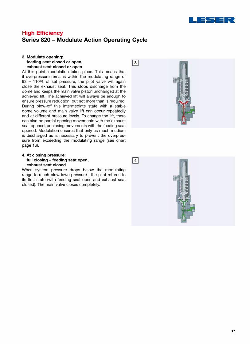
3. Modulate opening: feeding seat closed or open, exhaust seat closed or open
At this point, modulation takes place. This means that if overpressure remains within the modulating range of 93 – 110% of set pressure, the pilot valve will again close the exhaust seat. This stops discharge from the dome and keeps the main valve piston unchanged at the achieved lift. The achieved lift will always be enough to ensure pressure reduction, but not more than is required. During blow-off this intermediate state with a stable dome volume and main valve lift can occur repeatedly and at different pressure levels. To change the lift, there can also be partial opening movements with the exhaust seat opened, or closing movements with the feeding seat opened. Modulation ensures that only as much medium is discharged as is necessary to prevent the overpres-sure from exceeding the modulating range (see chart page 16).
4. At closing pressure: full closing – feeding seat open, exhaust seat closed
When system pressure drops below the modulating range to reach blowdown pressure , the pilot returns to its first state (with feeding seat open and exhaust seat closed). The main valve closes completely.

1818
High EfficiencyMaterials Series 810, 820 – Main valve
Below is a schematic drawing of the parts layout for the LESER POSV main valve including both the Standard and Extra Orifice designs. For the related parts listing, see opposite page.
55 Stud
56 Nut
9 Top plate
60 O-ring, inner top plate seal
67 O-ring, outer top plate seal
59 Dome spring
8 Piston guide
6 Piston, complete
58 Screw
7 O-ring disc, complete
5 Nozzle
62 Backup ring
61 O-ring, seat seal
2 Pitot tube
4 Fitting
63 O-ring, pitot tube
3 Tube
1 Body
6.2 Piston top
6.3 O-ring piston
6.5 Guide ring
6.4 Backup ring
6.1 Piston body
7.1 O-ring disc
7.3 O-ring
6.5 Guide ring
7.2 Disc retainer
6.6 Allen head screw
7.4 Nut
Option: Full nozzle design

1919
High EfficiencyMaterials Series 810, 820 – Main valve
MaterialsItem Component Type 8112 / 8212 Type 8114 / 8214 Type 8113 / 8213
1 Body1.0619 1.4408
SA 216 WCB SA 351 CF8M SA 352 LCB
2 Pitot tube1.4404 1.4404 1.4404316L 316L 316L
3 Tube1.4404 1.4404 1.4404316L 316L 316L
4 Fitting1.4404 1.4404 1.4404316L 316L 316L
5 Nozzle1.4404 1.4404 1.4404316L 316L 316L
6 Piston, complete
1.4404 1.4404 1.4404316L 316L 316L
6.1 Piston body1.4404 1.4404 1.4404316L 316L 316L
6.2 Piston top1.4404 1.4404 1.4404316L 316L 316L
6.4 Backup ringPTFE PTFE PTFEPTFE PTFE PTFE
6.5 Guide ringPTFE with carbon PTFE with carbon PTFE with carbonPTFE with carbon PTFE with carbon PTFE with carbon
6.6 Allen head screwA4-70 A4-70 A4-70
Stainless steel Stainless steel Stainless steel
7 O-ring disc, complete
1.4404 1.4404 1.4404316L 316L 316L
7.1 O-ring disc1.4404 1.4404 1.4404316L 316L 316L
7.2 Disc retainer1.4404 1.4404 1.4404316L 316L 316L
7.4 NutA4-70 A4-70 A4-70
Stainless steel Stainless steel Stainless steel
8 Piston guide1.4404 1.4404 1.4404316L 316L 316L
9 Top plate1.0460 1.4404 1.4404SA 105 316L 316L
55 Stud1.7225 1.4401 1.4401B7M B8M B8M
56 Nut1.7225 1.4401 1.4401
2H 8M 8M
58 ScrewA4-70 A4-70 A4-70
Stainless steel Stainless steel Stainless steel
59 Dome spring1.4310 1.4310 1.4310
Stainless steel Stainless steel Stainless steel
62 Backup ringPTFE PTFE PTFEPTFE PTFE PTFE
Option code
6.3, 6.4, 7.3, 60, 61, 63,
67
O-ring1)
* Viton® (FKM – Fluorocarbon)
R05 Buna-EP® (EPDM – Ethylene-Propylene-Dine)
R06 Kalrez® (FFKM – Perfluor)
Please notice:
– Modifications reserved by LESER.– LESER can upgrade materials without notice.– Every part can be replaced by other material acc. to customer specification.
1) For further soft seal materials refer to page 69 Extended Catalog

2020
High EfficiencyMaterials Series 810 – Pop Action Pilot Valve
Below is a schematic drawing of the parts layout for the LESER Series 810 – Pop Action pilot valve.For the related parts listing, see opposite page.
Bug screen 64
Please notice:
– Modifications reserved by LESER.– LESER can upgrade materials without notice.– Every part can be replaced by other material
acc. to customer specification.
40 Cap
18 Adjusting screw
19 Lock nut
16 Spring plate (upper)
54 Spring
17 Spring plate (lower)
31 O-ring, seat seal
5 Seat feeding
20 Nut
12 Adjusting screw
10 Bonnet, base part
14 Seat, exhaust (lower)
32 O-ring
9 Bonnet
11 Piston guide
13 Seat, exhaust (upper)
30 O-ring, seat seal
33 Backup ring
2 Guide
15 Plunger
33 Backup ring
21 Counter nut
35 Gasket
32 O-ring, piston seal
7 Disc, feeding (upper)
8 Disc, feeding (lower)
1 Body

2121
High EfficiencyMaterials Series 810 – Pop Action Pilot Valve
MaterialsItem Component Standard NACE
1 Body1.4404 1.4404
SA 479 316L SA 479 316L
2 Guide1.4404 1.4404
316L 316L
5 Seat, feeding1.4404 1.4404
316L 316L
7 Disc, feeding (upper)1.4404 1.4404
316L 316L
8 Disc, feeding (lower)1.4404 1.4404
316L 316L
9 Bonnet1.4404 1.4404
SA 479 316L SA 479 316L
10 Bonnet, base part1.4404 1.4404
SA 479 316L SA 479 316L
11 Piston guide1.4404 1.4404
316L 316L
12 Adjusting screw1.4404 1.4404
316L 316L
13 Seat, exhaust (upper)1.4404 1.4404
316L 316L
14 Seat, exhaust (lower)1.4404 1.4404
316L 316L
15 Plunger1.4404 1.4404
316L 316L
16 / 17 Spring plate (upper and lower)
1.4404 1.4404
316L 316L
18 Adjusting screw1.4404 1.4404
316L 316L
19 Lock nut1.4404 1.4404
316L 316L
20 Nut1.4404 1.4404
316L 316L
21 Counter nut1.4404 1.4404
316L 316L
26 Piston1.4404 1.4404
316L 316L
33 Backup ringPTFE PTFE
for set pressures 151 – 256 bar only for set pressures 151 – 256 bar only
35 GasketPTFE PTFE
40 Cap1.4404 1.4404
316L 316L
54 Spring1.4310 2.4669
Stainless steel INCONEL X750
64 Bug screenPlastic Plastic
Plastic Plastic
Option code
30, 31, 32 O-ring1)
* Viton® (FKM – Fluorocarbon)
R05 Buna-EP® (EPDM – Ethylene-Propylene-Dine)
R06 Kalrez® (FFKM – Perfluor)
1) For further soft seal materials refer to page 69 Extended Catalog
2222
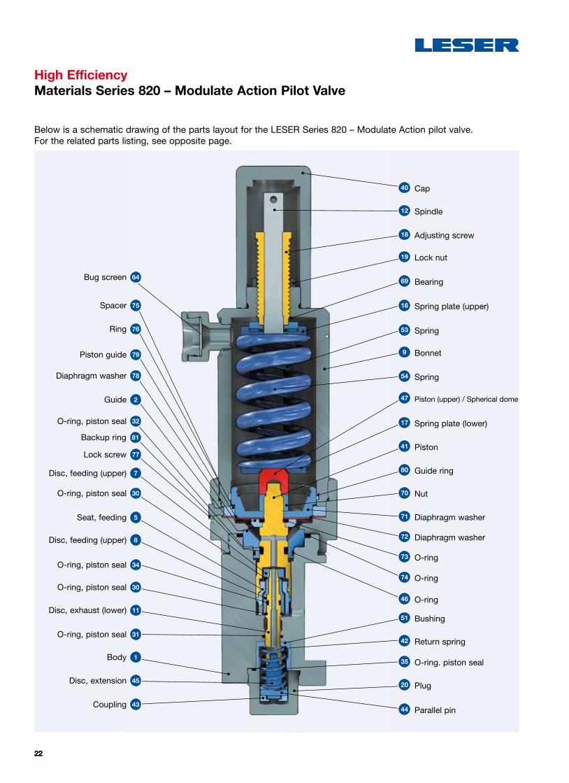
High EfficiencyMaterials Series 820 – Modulate Action Pilot Valve
Below is a schematic drawing of the parts layout for the LESER Series 820 – Modulate Action pilot valve.For the related parts listing, see opposite page.
Bug screen 64
Spacer 75
Ring 76
Piston guide 79
Diaphragm washer 78
Guide 2
O-ring, piston seal 32
O-ring, piston seal 30
Lock screw 77
Seat, feeding 5
Disc, feeding (upper) 7
Disc, feeding (upper) 8
O-ring, piston seal 34
O-ring, piston seal 31
Body 1
Disc, extension 45
Coupling 43
O-ring, piston seal 30
Disc, exhaust (lower) 11
40 Cap
12 Spindle
18 Adjusting screw
19 Lock nut
69 Bearing
16 Spring plate (upper)
53 Spring
9 Bonnet
54 Spring
17 Spring plate (lower)
41 Piston
80 Guide ring
70 Nut
71 Diaphragm washer
72 Diaphragm washer
42 Return spring
73 O-ring
35 O-ring. piston seal
74 O-ring
20 Plug
44 Parallel pin
46 O-ring
51 Bushing
47 Piston (upper) / Spherical dome
Backup ring 81

2323
High EfficiencyMaterials Series 820 – Modulate Action Pilot Valve
MaterialsItem Component Piston Diaphragm
1 Body1.4404 1.4404
SA 479 316L SA 479 316L
2 Guide1.4404 1.4404
316L 316L
5 Seat, feeding1.4404 1.4404
316L 316L
7 Disc, feeding (upper)1.4404 1.4404
316L 316L
8 Disc, feeding (lower)1.4404 1.4404
316L 316L
9 Bonnet1.4404 1.4404
SA 479 316L SA 479 316L
11Disc, exhaust
(lower)1.4404 1.4404
316L 316L
12 Spindle1.4404 1.4404
316L 316L
16 Spring plate (upper)1.4122 1.4122
Stainless steel Stainless steel
17 Spring plate (lower)1.4122 1.4122
Stainless steel Stainless steel
18 Adjusting screw1.4404 1.4404
316L 316L
19 Lock nut1.4404 1.4404
316L 316L
20 Plug1.4404 1.4404
316L 316L
40 Cap1.4404 1.4404
316L 316L
41 Piston1.4404 1.4404
316L 316L
42 Return spring2.4669 2.4669
INCONEL X750 INCONEL X750
43 Coupling1.4404 1.4404
316L 316L
44 Parallel pin Stainless steel Stainless steel
Stainless steel Stainless steel
Item Component Piston Diaphragm
45 Disc, extension1.4404 1.4404
316L 316L
47
Piston (upper)1.4404 –
316L –
Spherical dome– 1.4404
– 316L
51 Bushing1.4404 1.4404
316L 316L
54 Spring1.4310 1.4310
Stainless steel Stainless steel
64 Bug screenPlastic Plastic
Plastic Plastic
69 Bearing1.4122 1.4122
Stainless steel Stainless steel
70 Nut– 1.4401
– Stainless steel
71 Diaphragm washer– 1.4404
– 316L
72 Diaphragm– FKM
–
75 Spacer– 1.4404
– 316L
76 Ring– 1.4404
– 316L
77 Lock screw– 1.4401
– Stainless steel
78 Diaphragm washer– 1.4404
– 316L
80 Guide ring– 1.4404
– 316L
81 Backup ringPTFE –
– –
82 Backup ringPTFE –
– –
Please notice:
– Modifications reserved by LESER.– LESER can upgrade materials without notice.– Every part can be replaced by other material acc. to customer specification.
1) For further soft seal materials refer to page 69 Extended Catalog
MaterialsItem Component
Option code
30, 31, 32, 34, 35, 46, 73, 74
O-ring1)* Viton® (FKM – Fluorocarbon)
R05 Buna-EP® (EPDM – Ethylene-Propylene-Dine)
R06 Kalrez® (FFKM – Perfluor)

2424
High EfficiencyMaterials Series 810, 820 – Manifold block
Below is a schematic drawing of the parts layout for the Manifold block.For the related parts listing, see opposite page.
24.8 Gasket
24.7 Lock screw
24.1 Manifold block
24.6 O-ring
24.4 O-ring (Outlet)
24.3 Piston
24.4 O-ring (Outlet)
24.7 Lock screw
24.8 Gasket
Bushing 24.2
O-ring 24.5
O-ring (Exhaust Series 820) 24.6

2525
High EfficiencyMaterials Series 810, 820 – Manifold block
MaterialsItem Component Standard
24.1 Manifold block1.4404
316L
24.2 Bushing1.4404
316L
24.3 Piston1.4404
316L
24.7 Lock screw1.4101
Stainless steel
24.8 Gasket1.4101
Stainless steel
Option code
24.4, 24.5, 24.6
O-ring1)* Viton® (FKM – Fluorocarbon)
R05 Buna-EP® (EPDM – Ethylene-Propylene-Dine)
R06 Kalrez® (FFKM – Perfluor)
Please notice:
– Modifications reserved by LESER.– LESER can upgrade materials without notice.– Every part can be replaced by other material acc. to customer specification.
1) For further soft seal materials refer to page 69 Extended Catalog

2626
High EfficiencyArticle numbers – Series 810, Orifice D – K+
Type 811 WCB 1.0619 – Pop ActionValve size 1" x 2" 11/2" x 2" 11/2" x 3" 2" x 3"
Standard Orifice acc. to API 526
D E F D E F G H G H J
Extra Orifice G H J K+
Body material: WCB 1.0619
Flange class Art.-No.
150 x 150 8112. 0010 0020 0030 1820 0040 0050 0060 1830 0070 0080 1840 0090 0100 0110 1850
300 x 150 8112. 0220 0230 0240 1900 0250 0260 0270 1910 0280 0290 1920 0300 0310 0320 1930
300 x 3001) H65 8112. 1060 1070 1080 1090 1100 1110 1120 1130 1140 1150 1160
600 x 150 8112. 0640 0650 0660 2060 0670 0680 0690 2070 0700 0710 2080 0720 0730 0740 2090
600 x 3001) H67 8112. 1060 1070 1080 1090 1100 1110 1120 1130 1140 1150 1160
900 x 300 8112. 1060 1070 1080 1090 1100 1110 1120 1130 1140 1150 1160
1500 x 300 8112. 1240 1250 1260 1270 1280 1290 1300 1310 1320 1330 1340
1500 x 6001) 8112.
2500 x 300 8112.
2500 x 6001) 8112.
in preparation
1) Flange rating class 300 and 600: – in addition to API specification – different center to face dimensions – Article number and design of higher pressure types with additional option code.

2727
High EfficiencyArticle numbers – Series 810, Orifice J – T+
Type 811 WCB 1.0619 – Pop ActionValve size 3" x 4" 4" x 6" 6" x 8" 8" x 10"
Standard Orifice acc. to API 526
J K L L M N P Q R T
Extra Orifice N+ P+ R+ T+
Body material: WCB 1.0619
Flange class Art.-No.
150 x 150 8112. 0120 0130 0140 1860 0150 0160 0170 0180 1870 0190 0200 1880 0210 1890
300 x 150 8112. 0330 0340 0350 1940 0360 0370 0380 0390 1950 0400 0410 1960 0420 1970
300 x 3001) H65 8112. 1170 1180 1190 1200 1210 1220 1230 10302) 10402) 10502)
600 x 150 8112. 0750 0760 0770 2100 0780 0790 0800 0810 2110 0820 0830 2120 0840 2130
600 x 3001) H67 8112. 1170 1180 1190 1200 1210 1220 1230 10302) 10402) 10502)
900 x 300 8112. 1170 1180 1190 1200 1210 1220 1230
1500 x 300 8112. 1350 1360 1370 1380 1390 1400 1410
1500 x 6001) 8112.
2500 x 300 8112.
2500 x 6001) 8112.
in preparation
1) Flange rating class 300 and 600: – in addition to API specification – different center to face dimensions – Article number and design of higher pressure types with additional option code.
2) Delivery time 6 – 8 weeks

2828
High EfficiencyArticle numbers – Series 810, Orifice D – K+
Type 811 CF8M 1.4408 – Pop ActionValve size 1" x 2" 11/2" x 2" 11/2" x 3" 2" x 3"
Standard Orifice acc. to API 526
D E F D E F G H G H J
Extra Orifice G H J K+
Body material: CF8M 1.4408
Flange class Art.-No.
150 x 150 8114. 0010 0020 0030 1820 0040 0050 0060 1830 0070 0080 1840 0090 0100 0110 1850
300 x 150 8114. 0220 0230 0240 1900 0250 0260 0270 1910 0280 0290 1920 0300 0310 0320 1930
300 x 3001) H65 8114. 1060 1070 1080 1090 1100 1110 1120 1130 1140 1150 1160
600 x 150 8114. 0640 0650 0660 2060 0670 0680 0690 2070 0700 0710 2080 0720 0730 0740 2090
600 x 3001) H67 8114. 1060 1070 1080 1090 1100 1110 1120 1130 1140 1150 1160
900 x 300 8114. 1060 1070 1080 1090 1100 1110 1120 1130 1140 1150 1160
1500 x 300 8114. 1240 1250 1260 1270 1280 1290 1300 1310 1320 1330 1340
1500 x 6001) 8114.
2500 x 300 8114.
2500 x 6001) 8114.
1) Flange rating class 300 and 600: – in addition to API specification – different center to face dimensions – Article number and design of higher pressure types with additional option code.
in preparation

2929
High EfficiencyArticle numbers – Series 810, Orifice J – T+
Type 811 CF8M 1.4408 – Pop ActionValve size 3" x 4" 4" x 6" 6" x 8" 8" x 10"
Standard Orifice acc. to API 526
J K L L M N P Q R T
Extra Orifice N+ P+ R+ T+
Body material: CF8M 1.4408
Flange class Art.-No.
150 x 150 8114. 0120 0130 0140 1860 0150 0160 0170 0180 1870 0190 0200 1880 0210 1890
300 x 150 8114. 0330 0340 0350 1940 0360 0370 0380 0390 1950 0400 0410 1960 0420 1970
300 x 3001) H65 8114. 1170 1180 1190 1200 1210 1220 1230 10302) 10402) 10502)
600 x 150 8114. 0750 0760 0770 2100 0780 0790 0800 0810 2110 0820 0830 2120 0840 2130
600 x 3001) H67 8114. 1170 1180 1190 1200 1210 1220 1230 10302) 10402) 10502)
900 x 300 8114. 1170 1180 1190 1200 1210 1220 1230
1500 x 300 8114. 1350 1360 1370 1380 1390 1400 1410
1500 x 6001) 8114.
2500 x 300 8114.
2500 x 6001) 8114.
1) Flange rating class 300 and 600: – in addition to API specification – different center to face dimensions – Article number and design of higher pressure types with additional option code.
2) Delivery time 6 – 8 weeks
in preparation

3030
High EfficiencyArticle numbers – Series 810, Orifice D – K+
Type 811 LCB – Pop ActionValve size 1" x 2" 11/2" x 2" 11/2" x 3" 2" x 3"
Standard Orifice acc. to API 526
D E F D E F G H G H J
Extra Orifice G H J K+
Body material: LCB
Flange class Art.-No.
150 x 150 8113. 0010 0020 0030 1820 0040 0050 0060 1830 0070 0080 1840 0090 0100 0110 1850
300 x 150 8113. 0220 0230 0240 1900 0250 0260 0270 1910 0280 0290 1920 0300 0310 0320 1930
300 x 3001) H65 8113. 1060 1070 1080 1090 1100 1110 1120 1130 1140 1150 1160
600 x 150 8113. 0640 0650 0660 2060 0670 0680 0690 2070 0700 0710 2080 0720 0730 0740 2090
600 x 3001) H67 8113. 1060 1070 1080 1090 1100 1110 1120 1130 1140 1150 1160
900 x 300 8113. 1060 1070 1080 1090 1100 1110 1120 1130 1140 1150 1160
1500 x 300 8113. 1240 1250 1260 1270 1280 1290 1300 1310 1320 1330 1340
1500 x 6001) 8113.
2500 x 300 8113.
2500 x 6001) 8113.
1) Flange rating class 300 and 600: – in addition to API specification – different center to face dimensions – Article number and design of higher pressure types with additional option code.
in preparation

3131
High EfficiencyArticle numbers – Series 810, Orifice J – T+
Type 811 LCB – Pop ActionValve size 3" x 4" 4" x 6" 6" x 8" 8" x 10"
Standard Orifice acc. to API 526
J K L L M N P Q R T
Extra Orifice N+ P+ R+ T+
Body material: LCB
Flange class Art.-No.
150 x 150 8113. 0120 0130 0140 1860 0150 0160 0170 0180 1870 0190 0200 1880 0210 1890
300 x 150 8113. 0330 0340 0350 1940 0360 0370 0380 0390 1950 0400 0410 1960 0420 1970
300 x 3001) H65 8113. 1170 1180 1190 1200 1210 1220 1230 10302) 10402) 10502)
600 x 150 8113. 0750 0760 0770 2100 0780 0790 0800 0810 2110 0820 0830 2120 0840 2130
600 x 3001) H67 8113. 1170 1180 1190 1200 1210 1220 1230 10302) 10402) 10502)
900 x 300 8113. 1170 1180 1190 1200 1210 1220 1230
1500 x 300 8113. 1350 1360 1370 1380 1390 1400 1410
1500 x 6001) 8113.
2500 x 300 8113.
2500 x 6001) 8113.
1) Flange rating class 300 and 600: – in addition to API specification – different center to face dimensions – Article number and design of higher pressure types with additional option code.
2) Delivery time 6 – 8 weeks
in preparation

3232
High EfficiencyArticle numbers – Series 820, Orifice D – K+
Type 821 WCB 1.0619 – Modulate ActionValve size 1" x 2" 11/2" x 2" 11/2" x 3" 2" x 3"
Standard Orifice acc. to API 526
D E F D E F G H G H J
Extra Orifice G H J K+
Body material: WCB 1.0619
Flange class Art.-No.
150 x 150 8212. 0010 0020 0030 1820 0040 0050 0060 1830 0070 0080 1840 0090 0100 0110 1850
300 x 150 8212. 0220 0230 0240 1900 0250 0260 0270 1910 0280 0290 1920 0300 0310 0320 1930
300 x 3001) H65 8212. 1060 1070 1080 1090 1100 1110 1120 1130 1140 1150 1160
600 x 150 8212. 0640 0650 0660 2060 0670 0680 0690 2070 0700 0710 2080 0720 0730 0740 2090
600 x 3001) H67 8212. 1060 1070 1080 1090 1100 1110 1120 1130 1140 1150 1160
900 x 300 8212. 1060 1070 1080 1090 1100 1110 1120 1130 1140 1150 1160
1500 x 300 8212. 1240 1250 1260 1270 1280 1290 1300 1310 1320 1330 1340
1500 x 6001) 8212.
2500 x 300 8212.
2500 x 6001) 8212.
1) Flange rating class 300 and 600: – in addition to API specification – different center to face dimensions – Article number and design of higher pressure types with additional option code.
in preparation

3333
High EfficiencyArticle numbers – Series 820, Orifice J – T+
Type 821 WCB 1.0619 – Modulate ActionValve size 3" x 4" 4" x 6" 6" x 8" 8" x 10"
Standard Orifice acc. to API 526
J K L L M N P Q R T
Extra Orifice N+ P+ R+ T+
Body material: WCB 1.0619
Flange class Art.-No.
150 x 150 8212. 0120 0130 0140 1860 0150 0160 0170 0180 1870 0190 0200 1880 0210 1890
300 x 150 8212. 0330 0340 0350 1940 0360 0370 0380 0390 1950 0400 0410 1960 0420 1970
300 x 3001) H65 8212. 1170 1180 1190 1200 1210 1220 1230 10302) 10402) 10502)
600 x 150 8212. 0750 0760 0770 2100 0780 0790 0800 0810 2110 0820 0830 2120 0840 2130
600 x 3001) H67 8212. 1170 1180 1190 1200 1210 1220 1230 10302) 10402) 10502)
900 x 300 8212. 1170 1180 1190 1200 1210 1220 1230
1500 x 300 8212. 1350 1360 1370 1380 1390 1400 1410
1500 x 6001) 8212.
2500 x 300 8212.
2500 x 6001) 8212.
1) Flange rating class 300 and 600: – in addition to API specification – different center to face dimensions – Article number and design of higher pressure types with additional option code.
2) Delivery time 6 – 8 weeks
in preparation
3434
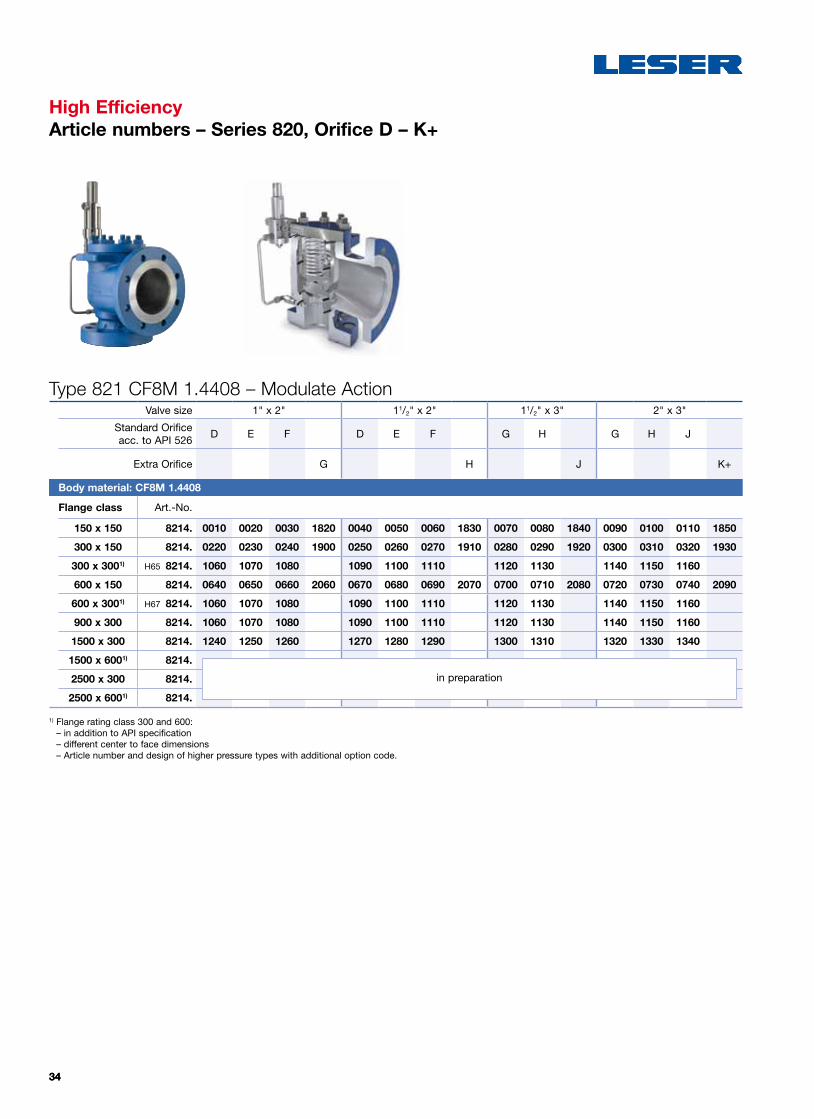
High EfficiencyArticle numbers – Series 820, Orifice D – K+
Type 821 CF8M 1.4408 – Modulate ActionValve size 1" x 2" 11/2" x 2" 11/2" x 3" 2" x 3"
Standard Orifice acc. to API 526
D E F D E F G H G H J
Extra Orifice G H J K+
Body material: CF8M 1.4408
Flange class Art.-No.
150 x 150 8214. 0010 0020 0030 1820 0040 0050 0060 1830 0070 0080 1840 0090 0100 0110 1850
300 x 150 8214. 0220 0230 0240 1900 0250 0260 0270 1910 0280 0290 1920 0300 0310 0320 1930
300 x 3001) H65 8214. 1060 1070 1080 1090 1100 1110 1120 1130 1140 1150 1160
600 x 150 8214. 0640 0650 0660 2060 0670 0680 0690 2070 0700 0710 2080 0720 0730 0740 2090
600 x 3001) H67 8214. 1060 1070 1080 1090 1100 1110 1120 1130 1140 1150 1160
900 x 300 8214. 1060 1070 1080 1090 1100 1110 1120 1130 1140 1150 1160
1500 x 300 8214. 1240 1250 1260 1270 1280 1290 1300 1310 1320 1330 1340
1500 x 6001) 8214.
2500 x 300 8214.
2500 x 6001) 8214.
1) Flange rating class 300 and 600: – in addition to API specification – different center to face dimensions – Article number and design of higher pressure types with additional option code.
in preparation

3535
High EfficiencyArticle numbers – Series 820, Orifice J – T+
Type 821 CF8M 1.4408 – Modulate ActionValve size 3" x 4" 4" x 6" 6" x 8" 8" x 10"
Standard Orifice acc. to API 526
J K L L M N P Q R T
Extra Orifice N+ P+ R+ T+
Body material: CF8M 1.4408
Flange class Art.-No.
150 x 150 8214. 0120 0130 0140 1860 0150 0160 0170 0180 1870 0190 0200 1880 0210 1890
300 x 150 8214. 0330 0340 0350 1940 0360 0370 0380 0390 1950 0400 0410 1960 0420 1970
300 x 3001) H65 8214. 1170 1180 1190 1200 1210 1220 1230 10302) 10402) 10502)
600 x 150 8214. 0750 0760 0770 2100 0780 0790 0800 0810 2110 0820 0830 2120 0840 2130
600 x 3001) H67 8214. 1170 1180 1190 1200 1210 1220 1230 10302) 10402) 10502)
900 x 300 8214. 1170 1180 1190 1200 1210 1220 1230
1500 x 300 8214. 1350 1360 1370 1380 1390 1400 1410
1500 x 6001) 8214.
2500 x 300 8214.
2500 x 6001) 8214.
1) Flange rating class 300 and 600: – in addition to API specification – different center to face dimensions – Article number and design of higher pressure types with additional option code.
2) Delivery time 6 – 8 weeks
in preparation

3636
High EfficiencyArticle numbers – Series 820, Orifice D – K+
Type 821 LCB – Modulate ActionValve size 1" x 2" 11/2" x 2" 11/2" x 3" 2" x 3"
Standard Orifice acc. to API 526
D E F D E F G H G H J
Extra Orifice G H J K+
Body material: LCB
Flange class Art.-No.
150 x 150 8213. 0010 0020 0030 1820 0040 0050 0060 1830 0070 0080 1840 0090 0100 0110 1850
300 x 150 8213. 0220 0230 0240 1900 0250 0260 0270 1910 0280 0290 1920 0300 0310 0320 1930
300 x 3001) H65 8213. 1060 1070 1080 1090 1100 1110 1120 1130 1140 1150 1160
600 x 150 8213. 0640 0650 0660 2060 0670 0680 0690 2070 0700 0710 2080 0720 0730 0740 2090
600 x 3001) H67 8213. 1060 1070 1080 1090 1100 1110 1120 1130 1140 1150 1160
900 x 300 8213. 1060 1070 1080 1090 1100 1110 1120 1130 1140 1150 1160
1500 x 300 8213. 1240 1250 1260 1270 1280 1290 1300 1310 1320 1330 1340
1500 x 6001) 8213.
2500 x 300 8213.
2500 x 6001) 8213.
1) Flange rating class 300 and 600: – in addition to API specification – different center to face dimensions – Article number and design of higher pressure types with additional option code.
in preparation
3737
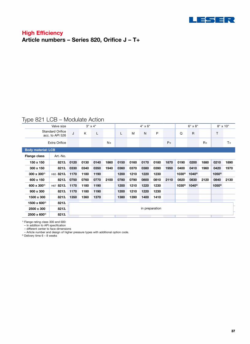
High EfficiencyArticle numbers – Series 820, Orifice J – T+
Type 821 LCB – Modulate ActionValve size 3" x 4" 4" x 6" 6" x 8" 8" x 10"
Standard Orifice acc. to API 526
J K L L M N P Q R T
Extra Orifice N+ P+ R+ T+
Body material: LCB
Flange class Art.-No.
150 x 150 8213. 0120 0130 0140 1860 0150 0160 0170 0180 1870 0190 0200 1880 0210 1890
300 x 150 8213. 0330 0340 0350 1940 0360 0370 0380 0390 1950 0400 0410 1960 0420 1970
300 x 3001) H65 8213. 1170 1180 1190 1200 1210 1220 1230 10302) 10402) 10502)
600 x 150 8213. 0750 0760 0770 2100 0780 0790 0800 0810 2110 0820 0830 2120 0840 2130
600 x 3001) H67 8213. 1170 1180 1190 1200 1210 1220 1230 10302) 10402) 10502)
900 x 300 8213. 1170 1180 1190 1200 1210 1220 1230
1500 x 300 8213. 1350 1360 1370 1380 1390 1400 1410
1500 x 6001) 8213.
2500 x 300 8213.
2500 x 6001) 8213.
1) Flange rating class 300 and 600: – in addition to API specification – different center to face dimensions – Article number and design of higher pressure types with additional option code.
2) Delivery time 6 – 8 weeks
in preparation

3838
Temperature range
T [°C] -29 38 93 149 204
T [°F] -20 100 200 300 400
Inlet flange rating class
Pressure range [psig]
150 285 285 260 230 200
300 740 740 680 655 635
600 1480 1480 1360 1310 1265
900 2220 2220 2035 1965 1900
1500 3705 3705 3395 3270 3170
2500 6170 6170 5655 5450 5280
Body material: WCB
Temperature range
T [°C] -29 38 93 149 204
T [°F] -20 100 200 300 400
Inlet flange rating class
Pressure range [psig]
150 265 265 255 230 200
300 695 695 660 640 615
600 1395 1395 1320 1275 1230
900 2090 2090 1980 1915 1845
1500 3480 3480 3300 3190 3075
2500 5805 5805 5505 5315 5125
Body material: LCB
Temperature range
T [°C] -29 38 93 149 204
T [°F] -20 100 200 300 400
Inlet flange rating class
Pressure range [psig]
150 275 275 235 215 195
300 720 720 620 560 515
600 1440 1440 1240 1120 1025
900 2160 2160 1860 1680 1540
1500 3600 3600 3095 2795 2570
2500 6000 6000 5160 4660 4280
Body material: CF8M
High EfficiencyPressure temperature ratings (ASME)

3939
A D
B
C
H
a
bE
S1
S2
Explanations
High EfficiencyDimensions and weights – Overview
d0 = Actual discharge diameter [mm] | [inch]A0 = Actual discharge area [mm2] | [inch2]a = Center to face [mm] | [inch]b = Center to face [mm] | [inch]H = Heights [mm] | [inch]S1 = Inlet flange thickness [mm] | [inch]S2 = Outlet flange thickness [mm] | [inch]
A = Bracket [mm] | [inch]B = Bracket [mm] | [inch]C = Hole diameter [mm] | [inch]D = Total width [mm] | [inch]E = Total length [mm] | [inch]m = Weight [kg] | [lbs]

4040
High EfficiencyDimensions and weights – Semi nozzle
Metric units – Orifice D – K+DN I+O 25 x 50 40 x 50 40 x 80 50 x 80
Valve size 1" x 2" 1 1/2" x 2" 1 1/2" x 3" 2" x 3"API Orifice D E F D E F G H G H J
Extra Orifice G H J K+d0 11 14.7 18.4 23 11 14.7 18.4 29 23,6 29.4 35.7 23.6 29.4 38 48A0 95 170 266 415 95 170 266 661 437 679 1001 437 679 1134 1810
Flange rating class 150 x 150a 105 105 105 105 124 124 124 124 130 130 130 137 137 137 137b 114 114 114 114 121 121 121 121 124 124 124 124 124 124 124
H Series 810 330 330 330 330 359 359 359 359 370 370 370 386 386 386 386H Series 820 456 456 456 456 485 485 485 485 496 496 496 512 512 512 512
S1 20 20 20 20 31 31 31 31 31 31 31 36 36 36 36S2 24 24 24 24 24 24 24 24 29 29 29 29 29 29 29A 143 143 143 143 152 152 152 152 160 160 160 179 179 179 179B – – – – – – – – – – – – – – –C 14 14 14 14 14 14 14 14 14 14 14 14 14 14 14D 182 182 182 182 186 186 186 186 200 200 200 209 209 209 209E 283 283 283 283 296 296 296 296 304 304 304 311 311 311 311m 22,5 22,5 22,5 22,5 27 27 27 27 31 31 31 37 37 37 37
Flange rating class 300 x 150a 111 111 111 111 124 124 124 124 130 130 130 137 137 137 137b 114 114 114 114 121 121 121 121 124 124 124 124 124 124 124
H Series 810 336 336 336 336 359 359 359 359 370 370 370 386 386 386 386H Series 820 462 462 462 462 485 485 485 485 496 496 496 512 512 512 512
S1 26 26 26 26 31 31 31 31 31 31 31 36 36 36 36S2 24 24 24 24 24 24 24 24 29 29 29 29 29 29 29A 143 143 143 143 152 152 152 152 160 160 160 179 179 179 179B – – – – – – – – – – – – – – –C 14 14 14 14 14 14 14 14 14 14 14 14 14 14 14D 182 182 182 182 186 186 186 186 200 200 200 209 209 209 209E 283 283 283 283 296 296 296 296 304 304 304 311 311 311 311m 19,5 19,5 19,5 19,5 24 24 24 24 28 28 28 34 34 34 34
Flange rating class 300 x 300a 125 125 125 – 149 149 149 149 162 162 – 167 167 167 –b 121 121 121 – 140 140 140 140 172 172 – 172 172 172 –
H Series 810 383 383 383 – 418 418 418 418 434 434 – 449 449 449 –H Series 820 456 456 456 – 491 491 491 491 507 507 – 522 522 522 –
S1 35 35 35 – 38 38 38 38 38 38 – 46 46 46 –S2 27 27 27 – 29 29 29 29 35 35 – 35 35 35 –A 153 153 153 – 165 165 165 165 173 173 – 207 207 207 –B – – – – – – – – – – – – – – –C 14 14 14 – 14 14 14 14 14 14 – 14 14 14 –D 183 183 183 – 195 195 195 195 203 203 – 237 237 237 –E 296 296 296 – 320 320 320 320 357 357 – 374 374 374 –m 25 25 25 – 32 32 32 32 37 37 – 54 54 54 –
Flange rating class 600 x 150a 111 111 111 111 124 124 124 124 130 130 130 137 137 137 137b 114 114 114 114 121 121 121 121 124 124 124 124 124 124 124
H Series 810 336 336 336 336 359 359 359 359 370 370 370 386 386 386 386H Series 820 462 462 462 462 485 485 485 485 496 496 496 512 512 512 512
S1 26 26 26 26 31 31 31 31 31 31 31 36 36 36 36S2 24 24 24 24 24 24 24 24 29 29 29 29 29 29 29A 143 143 143 143 152 152 152 152 160 160 160 179 179 179 179B – – – – – – – – – – – – – – –C 14 14 14 14 14 14 14 14 14 14 14 14 14 14 14D 182 182 182 182 186 186 186 186 200 200 200 209 209 209 209E 283 283 283 283 296 296 296 296 304 304 304 311 311 311 311m 22,5 22,5 22,5 22,5 27 27 27 27 31 31 31 37 37 37 37
4141
High EfficiencyDimensions and weights – Semi nozzle
Metric units – Orifice J – T+DN I+O 80 x 100 100 x 150 150 x 200 200 x 250
Valve size 3" x 4" 4" x 6" 6" x 8" 8" x 10"Orifice J K L L M N P Q R T
Extra Orifice N+ P+ R+ T+d0 38 45 56 75 56 63 69 83 95 110 133 142 168 180A0 1134 1590 2463 4418 2463 3117 3739 5411 7088 9503 13893 15837 22167 25447
Flange rating class 150 x 150a 156 156 156 156 197 197 197 197 197 240 240 240 276 276b 162 162 162 162 210 210 210 210 210 241 241 241 279 279
H Series 810 428 428 428 428 481 481 481 481 481 580 580 580 683 683H Series 820 554 554 554 554 607 607 607 607 607 706 706 706 809 809
S1 36 36 36 36 49 49 49 49 49 52 52 52 45 45S2 29 29 29 29 30 30 30 30 30 47 47 47 35 35A 223 223 223 223 249 249 249 249 249 320 320 320 356 356B 110 110 110 110 110 110 110 110 110 160 160 160 160 160C 18 18 18 18 18 18 18 18 18 18 18 18 18 18D 259 259 259 259 305 305 305 305 305 381 381 381 430 430E 370 370 370 370 432 432 432 432 432 528 528 528 561 561m 59 59 59 59 89 89 89 89 89 195 195 195 263 263
Flange rating class 300 x 150a 156 156 156 156 197 197 197 197 197 240 240 240 276 276b 162 162 162 162 210 210 210 210 210 241 241 241 279 279
H Series 810 428 428 428 428 481 481 481 481 481 580 580 580 683 683H Series 820 554 554 554 554 607 607 607 607 607 706 706 706 809 809
S1 36 36 36 36 49 49 49 49 49 52 52 52 45 45S2 29 29 29 29 30 30 30 30 30 47 47 47 35 35A 223 223 223 223 249 249 249 249 249 320 320 320 356 356B 110 110 110 110 110 110 110 110 110 160 160 160 160 160C 18 18 18 18 18 18 18 18 18 18 18 18 18 18D 259 259 259 259 305 305 305 305 305 381 381 381 430 430E 370 370 370 370 432 432 432 432 432 528 528 528 561 561m 59 59 59 59 89 89 89 89 89 195 195 195 263 263
Flange rating class 300 x 300a 191 191 191 – 249 249 249 249 – – – – – –b 181 181 181 – 233 233 233 233 – – – – – –
H Series 810 496 496 496 – 567 567 567 567 – – – – – –H Series 820 569 569 569 – 640 640 640 640 – – – – – –
S1 56 56 56 – 62 62 62 62 – – – – – –S2 36 36 36 – 43 43 43 43 – – – – – –A 242 242 242 – 265 265 265 265 – – – – – –B 110 110 110 – 110 110 110 110 – – – – – –C 18 18 18 – 18 18,0 18 18 – – – – – –D 278 278 278 – 304 304 304 304 – – – – – –E 402 402 402 – 466 466 466 466 – – – – – –m 89 89 89 – 132 132 132 132 – – – – – –
Flange rating class 600 x 150a 162 162 162 162 197 197 197 197 197 246 246 246 297 297b 162 162 162 162 210 210 210 210 210 241 241 241 279 279
H Series 810 434 434 434 434 481 481 481 481 481 586 586 586 689 689H Series 820 560 560 560 560 607 607 607 607 607 712 712 712 815 815
S1 42 42 42 42 49 49 49 49 49 58 58 58 66 66S2 29 29 29 29 30 30 30 30 30 47 47 47 35 35A 223 223 223 223 249 249 249 249 249 320 320 320 356 356B 110 110 110 110 110 110 110 110 110 160 160 160 160 160C 18 18 18 18 18 18 18 18 18 18 18 18 18 18D 259 259 259 259 305 305 305 305 305 381 381 381 430 430E 370 370 370 370 432 432 432 432 432 528 528 528 561 561m 59 59 59 59 89 89 89 89 89 195 195 195 263 263

4242
High EfficiencyDimensions and weights – Semi nozzle
Metric units – Orifice D – K+DN I+O 25 x 50 40 x 50 40 x 80 50 x 80
Valve size 1" x 2" 1 1/2" x 2" 1 1/2" x 3" 2" x 3"API Orifice D E F D E F G H G H J
Extra Orifice G H J K+d0 11 14.7 18.4 23 11 14.7 18.4 29 23,6 29.4 35.7 23.6 29.4 38 48A0 95 170 266 415 95 170 266 661 437 679 1001 437 679 1134 1810
Flange rating class 600 x 300a 125 125 125 – 149 149 149 149 162 162 – 167 167 167 –b 121 121 121 – 140 140 140 140 172 172 – 172 172 172 –
H Series 810 383 383 383 – 418 418 418 418 434 434 – 449 449 449 –H Series 820 456 456 456 – 491 491 491 491 507 507 – 522 522 522 –
S1 35 35 35 – 38 38 38 38 38 38 – 46 46 46 –S2 27 27 27 – 29 29 29 29 35 35 – 35 35 35 –A 153 153 153 – 165 165 165 165 173 173 – 207 207 207 –B – – – – – – – – – – – – – – –C 14 14 14 – 14 14 14 14 14 14 – 14 14 14 –D 183 183 183 – 195 195 195 195 203 203 – 237 237 237 –E 296 296 296 – 320 320 320 320 357 357 – 374 374 374 –m 25 25 25 – 32 32 32 32 37 37 – 54 54 54 –
Flange rating class 900 x 300a 125 125 125 – 149 149 149 149 162 162 – 167 167 167 –b 121 121 121 – 140 140 140 140 172 172 – 172 172 172 –
H Series 810 383 383 383 – 418 418 418 418 434 434 – 449 449 449 –H Series 820 456 456 456 – 491 491 491 491 507 507 – 522 522 522 –
S1 35 35 35 – 38 38 38 38 38 38 – 46 46 46 –S2 27 27 27 – 29 29 29 29 35 35 – 35 35 35 –A 153 153 153 – 165 165 165 165 173 173 – 207 207 207 –B – – – – – – – – – – – – – – –C 14 14 14 – 14 14 14 14 14 14 – 14 14 14 –D 183 183 183 – 195 195 195 195 203 203 – 237 237 237 –E 296 296 296 – 320 320 320 320 357 357 – 374 374 374 –m 25 25 25 – 32 32 32 32 37 37 – 54 54 54 –
Flange rating class 1500 x 300a 125 125 125 – 149 149 149 149 162 162 – 167 167 167 –b 121 121 121 – 140 140 140 140 172 172 – 172 172 172 –
H Series 810 383 383 383 – 418 418 418 418 434 434 – 449 449 449 –H Series 820 456 456 456 – 491 491 491 491 507 507 – 522 522 522 –
S1 35 35 34,8 – 38 38 38 38 38 38 – 46 46 46 –S2 27 27 27 – 29 29 29 29 35 35 – 35 35 35 –A 153 153 153 – 165 165 165 165 173 173 – 207 207 207 –B – – – – – – – – – – – – – – –C 14 14 14 – 14 14 14 14 14 14 – 14 14 14 –D 183 183 183 – 195,0 195 195 195 203 203 – 237 237 237 –E 296 296 296 – 320 320 320 320 357 357 – 374 374 374 –m 25 25 25 – 32 32 32 32 37 37 – 54 54 54 –

4343
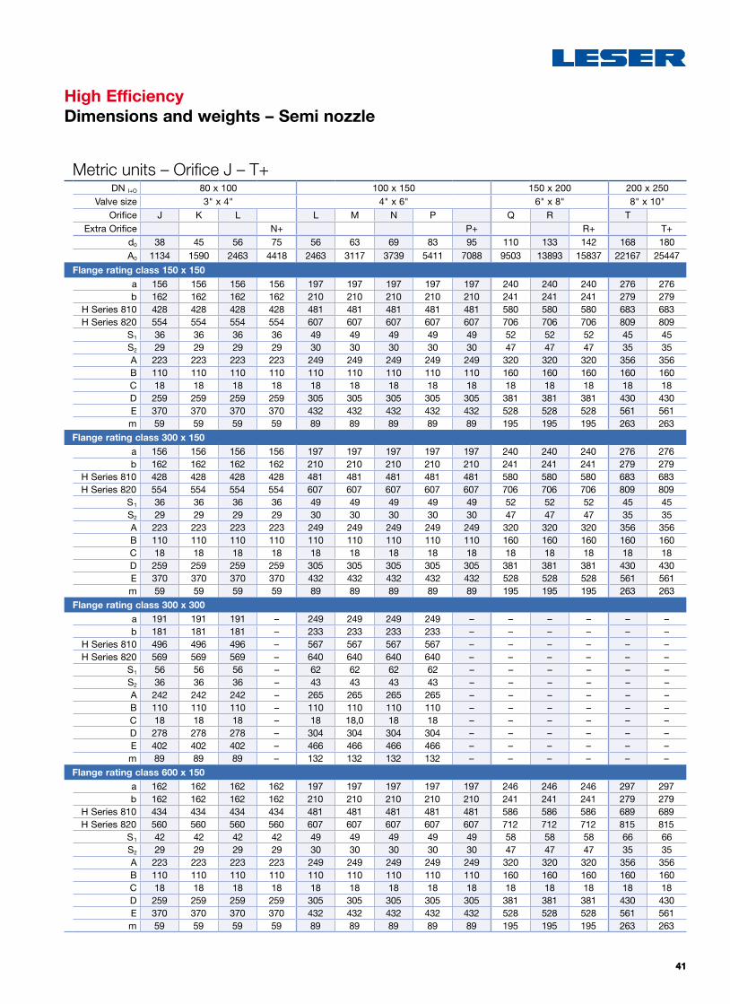
High EfficiencyDimensions and weights – Semi nozzle
Metric units – Orifice J – T+DN I+O 80 x 100 100 x 150 150 x 200 200 x 250
Valve size 3" x 4" 4" x 6" 6" x 8" 8" x 10"Orifice J K L L M N P Q R T
Extra Orifice N+ P+ R+ T+d0 38 45 56 75 56 63 69 83 95 110 133 142 168 180A0 1134 1590 2463 4418 2463 3117 3739 5411 7088 9503 13893 15837 22167 25447
Flange rating class 600 x 300a 191 191 191 – 249 249 249 249 – – – – – –b 181 181 181 – 233 233 233 233 – – – – – –
H Series 810 496 496 496 – 567 567 567 567 – – – – – –H Series 820 569 569 569 – 640 640 640 640 – – – – – –
S1 56 56 56 – 62 62 62 62 – – – – – –S2 36 36 36 – 43 43 43 43 – – – – – –A 242 242 242 – 265 265 265 265 – – – – – –B 110 110 110 – 110 110 110 110 – – – – – –C 18 18 18 – 18 18 18 18 – – – – – –D 278 278 278 – 304 304 304 304 – – – – – –E 402 402 402 – 466 466 466 466 – – – – – –m 89 89 89 – 132 132 132 132 – – – – – –
Flange rating class 900 x 300a 191 191 191 – 249 249 249 249 – – – – – –b 181 181 181 – 233 233 233 233 – – – – – –
H Series 810 496 496 496 – 567 567 567 567 – – – – – –H Series 820 569 569 569 – 640 640 640 640 – – – – – –
S1 56 56 56 – 62 62 62 62 – – – – – –S2 36 36 36 – 43 43 43 43 – – – – – –A 242 242 242 – 265 265 265 265 – – – – – –B 110 110 110 – 110 110 110 110 – – – – – –C 18 18 18,0 – 18 18 18 18 – – – – – –D 278 278 278 – 304 304 304 304 – – – – – –E 402 402 402 – 466 466 466 466 – – – – – –m 89 89 89 – 132 132 132 132 – – – – – –
Flange rating class 1500 x 300a 191 191 191 – 249 249 249 249 – – – – – –b 181 181 181 – 233 233 233 233 – – – – – –
H Series 810 496 496 496 – 567 567 567 567 – – – – – –H Series 820 569 569 569 – 640 640 640 640 – – – – – –
S1 56 56 56 – 62 62 62 62 – – – – – –S2 36 36 36 – 43 43 43 43 – – – – – –A 242 242 242 – 265 265 265 265 – – – – – –B 110 110 110 – 110 110 110 110 – – – – – –C 18 18 18 – 18 18 18 18 – – – – – –D 278 278 278 – 304 304 304 304 – – – – – –E 402 402 402 – 466 466 466 466 – – – – – –m 89 89 89 – 132 132 132 132 – – – – – –

4444
High EfficiencyDimensions and weights – Semi nozzle
US units – Orifice D – K+DN I+O 25 x 50 40 x 50 40 x 80 50 x 80
Valve size 1" x 2" 1 1/2" x 2" 1 1/2" x 3" 2" x 3"API Orifice D E F D E F G H G H J
Extra Orifice G H J K+d0 0.433 0.579 0.724 0.906 0.433 0.579 0.724 1.142 0.929 1.157 1.406 0.929 1.157 1.496 1.890A0 0.147 0.264 0.412 0.644 0.147 0.264 0.412 1.024 0.678 1.052 1.552 0.678 1.052 1.758 2.805
Flange rating class 150 x 150a 4 1/8 4 1/8 4 1/8 4 1/8 4 7/8 4 7/8 4 7/8 4 7/8 5 1/8 5 1/8 5 1/8 5 3/8 5 3/8 5 3/8 5 3/8
b 4 1/2 4 1/2 4 1/2 4 1/2 4 3/4 4 3/4 4 3/4 4 3/4 4 7/8 4 7/8 4 7/8 4 7/8 4 7/8 4 7/8 4 7/8
H Series 810 13 13 13 13 14 4/32 14 4/32 14 4/32 14 4/32 14 5/8 14 5/8 14 5/8 15 6/32 15 6/32 15 6/32 15 6/32
H Series 820 18 18 18 18 19 1/8 19 1/8 19 1/8 19 1/8 19 5/8 19 5/8 19 5/8 20 6/32 20 6/32 20 6/32 20 6/32
S125/32
25/3225/32
25/32 1 7/32 1 7/32 1 7/32 1 7/32 1 7/32 1 7/32 1 7/32 1 13/32 1 13/32 1 13/32 1 13/32
S230/32
30/3230/32
30/3230/32
30/3230/32
30/32 1 5/32 1 5/32 1 5/32 1 5/32 1 5/32 1 5/32 1 5/32
A 5 5/8 5 5/8 5 5/8 5 5/8 6 6 6 6 6 5/16 6 5/16 6 5/16 7 1/16 7 1/16 7 1/16 7 1/16
B – – – – – – – – – – – – – – –C 9/16
9/169/16
9/169/16
9/169/16
9/169/16
9/169/16
9/169/16
9/169/16
D 7 3/16 7 3/16 7 3/16 7 3/16 7 5/16 7 5/16 7 5/16 7 5/16 7 14/16 7 14/16 7 14/16 8 4/16 8 4/16 8 4/16 8 4/16
E 11 5/32 11 5/32 11 5/32 11 5/32 11 21/32 11 21/32 11 21/32 11 21/32 11 31/32 11 31/32 11 31/32 12 1/4 12 1/4 12 1/4 12 1/4
m 49.6 49.6 49.6 49.6 59.5 59.5 59.5 59.5 68.3 68.3 68.3 81.6 81.6 81.6 81.6Flange rating class 300 x 150
a 4 3/8 4 3/8 4 3/8 4 3/8 4 7/8 4 7/8 4 7/8 4 7/8 5 1/8 5 1/8 5 1/8 5 3/8 5 3/8 5 3/8 5 3/8
b 4 1/2 4 1/2 4 1/2 4 1/2 4 3/4 4 3/4 4 3/4 4 3/4 4 7/8 4 7/8 4 7/8 4 7/8 4 7/8 4 7/8 4 7/8
H Series 810 13 7/32 13 7/32 13 7/32 13 7/32 14 4/32 14 4/32 14 4/32 14 4/32 14 5/8 14 5/8 14 5/8 15 6/32 15 6/32 15 6/32 15 6/32
H Series 820 18 2/8 18 2/8 182/8 182/8 19 1/8 19 1/8 19 1/8 19 1/8 19 5/8 19 5/8 19 5/8 20 6/32 20 6/32 20 6/32 20 6/32
S1 1 1/32 1 1/32 1 1/32 11/32 1 7/32 1 7/32 1 7/32 1 7/32 1 7/32 1 7/32 1 7/32 1 13/32 1 13/32 1 13/32 1 13/32
S230/32
30/3230/32
30/3230/32
30/3230/32
30/32 1 5/32 1 5/32 1 5/32 1 5/32 1 5/32 1 5/32 1 5/32
A 5 5/8 5 5/8 5 5/8 5 5/8 6 6 6 6 6 5/16 6 5/16 6 5/16 7 1/16 7 1/16 7 1/16 7 1/16
B – – – – – – – – – – – – – – –C 9/16
9/169/16
9/169/16
9/169/16
9/169/16
9/169/16
9/169/16
9/169/16
D 7 3/16 7 3/16 7 3/16 7 3/16 7 5/16 7 5/16 7 5/16 7 5/16 7 14/16 7 14/16 7 14/16 8 4/16 84/16 8 4/16 8 4/16
E 11 5/32 11 5/32 11 5/32 11 5/32 11 21/32 11 21/32 11 21/32 11 21/32 11 31/32 11 31/32 11 31/32 12 1/4 12 1/4 12 1/4 12 1/4
m 49.6 49.6 49.6 49.6 59.5 59.5 59.5 59.5 68.3 68.3 68.3 81.6 81.6 81.6 81.6Flange rating class 300 x 300
a 5 5 5 – 5 7/8 5 7/8 5 7/8 5 7/8 6 3/8 6 3/8 – 6 4/7 6 4/7 6 4/7 –b 4 3/4 4 3/4 4 3/4 – 5 1/2 5 1/2 5 1/2 5 1/2 6 3/4 6 3/4 – 6 3/4 6 3/4 6 3/4 –
H Series 810 15 15 15 – 16 1/2 16 1/2 16 1/2 16 1/2 17 17 – 17 2/3 17 2/3 17 2/3 –H Series 820 18 18 18 – 19 1/3 19 1/3 19 1/3 19 1/3 20 20 – 20 5/9 20 5/9 20 5/9 –
S1 1 3/8 1 3/8 1 3/8 – 1 1/2 1 1/2 1 1/2 1 1/2 1 1/2 1 1/2 – 1 4/5 1 4/5 1 4/5 –S2 1 1 1 – 1 1/8 1 1/8 1 1/8 1 1/8 1 3/8 1 3/8 – 1 3/8 1 3/8 1 3/8 –A 6 6 6 – 6 1/2 6 1/2 6 1/2 6 1/2 6 4/5 6 4/5 – 8 1/7 8 1/7 8 1/7 –B – – – – – – – – – – – – – – –C 5/9 5/9
5/9 – 5/95/9
5/95/9
5/95/9 – 5/9
5/95/9 –
D 7 1/5 7 1/5 7 1/5 – 7 2/3 7 2/3 7 2/3 7 2/3 8 8 – 9 1/3 9 1/3 9 1/3 –E 11 2/3 11 2/3 11 2/3 – 12 3/5 12 3/5 12 3/5 12 3/5 14 14 – 14 5/7 14 5/7 14 5/7 –m 54.4 54.4 54.4 – 70.5 70.5 70.5 70.5 81.5 81.5 – 119.5 119.5 119.5 –
Flange rating class 600 x 150a 4 3/8 4 3/8 4 3/8 4 3/8 4 7/8 4 7/8 4 7/8 4 7/8 5 1/8 5 1/8 5 1/8 5 3/8 5 3/8 5 3/8 5 3/8
b 4 1/2 41/2 4 1/2 4 1/2 4 3/4 4 3/4 4 3/4 4 3/4 4 7/8 4 7/8 4 7/8 4 7/8 4 7/8 4 7/8 4 7/8
H Series 810 13 7/32 13 7/32 13 7/32 13 7/32 14 4/32 14 4/32 14 4/32 14 4/32 14 5/8 14 5/8 14 5/8 15 6/32 15 6/32 15 6/32 15 6/32
H Series 820 18 2/8 18 2/8 18 2/8 18 2/8 19 1/8 19 1/8 19 1/8 19 1/8 19 5/8 19 5/8 19 5/8 20 6/32 20 6/32 20 6/32 20 6/32
S1 1 1/32 1 1/32 1 1/32 1 1/32 1 7/32 1 7/32 1 7/32 1 7/32 1 7/32 1 7/32 1 7/32 1 13/32 1 13/32 1 13/32 1 13/32
S230/32
30/3230/32
30/3230/32
30/3230/32
30/32 1 5/32 1 5/32 1 5/32 1 5/32 1 5/32 1 5/32 15/32
A 5 5/8 5 5/8 5 5/8 5 5/8 6 6 6 6 6 5/16 6 5/16 6 5/16 7 1/16 7 1/16 7 1/16 7 1/16
B – – – – – – – – – – – – – – –C 9/16
9/169/16
9/169/16
9/169/16
9/169/16
9/169/16
9/169/16
9/169/16
D 7 3/16 7 3/16 7 3/16 7 3/16 7 5/16 7 5/16 7 5/16 7 5/16 7 14/16 7 14/16 7 14/16 8 4/16 8 4/16 8 4/16 8 4/16
E 11 5/32 11 5/32 11 5/32 11 5/32 11 21/32 11 21/32 11 21/32 11 21/32 11 31/32 11 31/32 11 31/32 12 1/4 12 1/4 12 1/4 12 1/4
m 49.6 49.6 49.6 49.6 59.5 59.5 59.5 59.5 68.3 68.3 68.3 81.6 81.6 81.6 81.6

4545
High EfficiencyDimensions and weights – Semi nozzle
US units – Orifice J – T+DN I+O 80 x 100 100 x 150 150 x 200 200 x 250
Valve size 3" x 4" 4" x 6" 6" x 8" 8" x 10"Orifice J K L L M N P Q R T
Extra Orifice N+ P+ R+ T+d0 1.496 1.772 2.205 2.953 2.205 2.480 2.717 3.268 3.740 4.331 5.236 5.591 6.614 7.087A0 1.758 2.465 3.818 6.848 3.818 4.832 5.796 8.386 10.987 14.730 21.534 24.547 34.359 39.443
Flange rating class 150 x 150a 6 1/8 6 1/8 6 1/8 6 1/8 7 3/4 7 3/4 7 3/4 7 3/4 7 3/4 9 7/16 9 7/16 9 7/16 10 7/8 10 7/8
b 6 3/8 6 3/8 6 3/8 6 3/8 8 1/4 8 1/4 8 1/4 8 1/4 8 1/4 9 1/2 9 1/2 9 1/2 11 11H Series 810 16 27/32 16 27/32 16 27/32 16 27/32 18 15/16 18 15/16 18 15/16 18 15/16 18 15/16 22 27/32 22 27/32 22 27/32 26 2/8 26 2/8
H Series 820 21 14/16 21 14/16 21 14/16 21 14/16 23 15/16 23 15/16 23 15/16 23 15/16 23 15/16 27 13/16 27 13/16 27 13/16 31 5/16 31 5/16
S1 1 7/16 1 7/16 1 7/16 1 7/16 1 15/16 1 15/16 1 15/16 1 15/16 1 15/16 2 2/32 2 2/32 2 2/32 1 12/16 1 12/16
S2 1 2/16 1 2/16 1 2/16 1 2/16 1 3/16 1 3/16 1 3/16 1 3/16 1 3/16 1 27/32 1 27/32 1 27/32 1 6/16 1 6/16
A 8 25/32 8 25/32 8 25/32 8 25/32 9 13/16 9 13/16 9 13/16 9 13/16 9 13/16 12 19/32 12 19/32 12 19/32 14 1/32 14 1/32
B 4 11/32 4 11/32 4 11/32 4 11/32 4 11/32 4 11/32 4 11/32 4 11/32 4 11/32 6 5/16 6 5/16 6 5/16 6 5/16 6 5/16
C 23/3223/32
23/3223/32
23/3223/32
23/3223/32
23/3223/32
23/3223/32
23/3223/32
D 10 6/32 10 6/32 10 6/32 10 6/32 12 12 12 12 12 15 15 15 16 30/32 16 30/32
E 14 9/16 14 9/16 14 9/16 14 9/16 17 17 17 17 17 20 25/32 20 25/32 20 25/32 22 3/32 22 3/32
m 130.1 130.1 130.1 130.1 196.2 196.2 196.2 196.2 196.2 429.9 429.9 429.9 579.8 579.8Flange rating class 300 x 150
a 6 1/8 6 1/8 6 1/8 6 1/8 7 3/4 7 3/4 7 3/4 7 3/4 7 3/4 9 7/16 9 7/16 9 7/16 10 7/8 10 7/8
b 6 3/8 6 3/8 6 3/8 6 3/8 8 1/4 8 1/4 8 1/4 8 1/4 8 1/4 9 1/2 9 1/2 9 1/2 11 11H Series 810 16 27/32 16 27/32 16 27/32 16 27/32 18 15/16 18 15/16 18 15/16 18 15/16 18 15/16 22 27/32 22 27/32 22 27/32 26 7/8 26 7/8
H Series 820 21 14/16 21 14/16 21 14/16 21 14/16 23 15/16 23 15/16 23 15/16 23 15/16 23 15/16 27 13/16 27 13/16 27 13/16 31 14/16 31 14/16
S1 1 7/16 1 7/16 1 7/16 1 7/16 115/16 1 15/16 1 15/16 1 15/16 1 15/16 2 2/32 2 2/32 2 2/32 1 12/16 1 12/16
S2 1 2/16 1 2/16 1 2/16 1 2/16 1 3/16 1 3/16 1 3/16 1 3/16 1 3/16 1 27/32 1 27/32 1 27/32 1 6/16 1 6/16
A 8 25/32 8 25/32 8 25/32 8 25/32 9 13/16 9 13/16 9 13/16 9 13/16 9 13/16 12 19/32 12 19/32 12 19/32 14 1/32 14 1/32
B 4 11/32 4 11/32 4 11/32 4 11/32 4 11/32 4 11/32 4 11/32 4 11/32 4 11/32 6 5/16 6 5/16 6 5/16 6 5/16 6 5/16
C 23/3223/32
23/3223/32
23/3223/32
23/3223/32
23/3223/32
23/3223/32
23/3223/32
D 10 6/32 10 6/32 10 6/32 10 6/32 12 12 12 12 12 15 15 15 16 30/32 16 30/32
E 14 9/16 14 9/16 14 9/16 14 9/16 17 17 17 17 17 20 25/32 20 25/32 20 25/32 22 3/32 22 3/32
m 130.1 130.1 130.1 130.1 196.2 196.2 196.2 196.2 196.2 429.9 429.9 429.9 579.8 579.8Flange rating class 300 x 300
a 7 1/2 7 1/2 7 1/2 – 9 4/5 9 4/5 9 4/5 9 4/5 – – – – – –b 7 1/8 7 1/8 7 1/8 – 9 1/5 9 1/5 9 1/5 9 1/5 – – – – – –
H Series 810 19 1/2 19 1/2 19 1/2 – 22 1/3 22 1/3 22 1/3 22 1/3 – – – – – –H Series 820 22 2/5 22 2/5 22 2/5 – 25 1/5 25 1/5 25 1/5 25 1/5 – – – – – –
S1 2 1/5 2 1/5 2 1/5 – 2 3/7 2 3/7 2 3/7 2 3/7 – – – – – –S2 1 3/7 1 3/7 1 3/7 – 1 2/3 1 2/3 1 2/3 1 2/3 – – – – – –A 9 1/2 9 1/2 9 1/2 – 10 3/7 10 3/7 10 3/7 10 3/7 – – – – – –B 4 1/3 4 1/3 4 1/3 – 4 1/3 4 1/3 4 1/3 4 1/3 – – – – – –C 5/7
5/75/7 – 5/7 5/7
5/75/7 – – – – – –
D 11 11 11 – 12 12 12 12 – – – – – –E 15 5/6 15 5/6 15 5/6 – 18 1/3 18 1/3 18 1/3 18 1/3 – – – – – –m 195.7 195.7 195.7 – 290.9 290.9 290.9 290.9 – – – – – –
Flange rating class 600 x 150a 6 3/8 6 3/8 6 3/8 6 3/8 7 3/4 7 3/4 7 3/4 7 3/4 7 3/4 9 11/16 9 11/16 9 11/16 11 11/16 11 11/16
b 6 3/8 6 3/8 6 3/8 6 3/8 8 1/4 8 1/4 8 1/4 8 1/4 8 1/4 9 1/2 9 1/2 9 1/2 11 11H Series 810 17 3/32 17 3/32 17 3/32 17 3/32 18 15/16 18 15/16 18 15/16 18 15/16 18 15/16 23 2/32 23 2/32 23 2/32 27 1/8 27 1/8
H Series 820 22 1/16 22 1/16 22 1/16 221/16 23 15/16 23 15/16 23 15/16 23 15/16 23 15/16 28 1/16 28 1/16 28 1/16 32 2/16 32 2/16
S1 1 10/16 1 10/16 1 10/16 1 10/16 1 15/16 1 15/16 1 15/16 1 15/16 115/16 2 9/32 2 9/32 2 9/32 2 10/16 2 10/16
S2 1 2/16 1 2/16 1 2/16 1 2/16 1 3/16 1 3/16 1 3/16 1 3/16 1 3/16 1 27/32 1 27/32 1 27/32 1 6/16 1 6/16
A 8 25/32 8 25/32 8 25/32 8 25/32 9 13/16 913/16 913/16 913/16 913/16 1219/32 12 19/32 12 19/32 14 1/32 14 1/32
B 4 11/32 4 11/32 4 11/32 4 11/32 4 11/32 4 11/32 4 11/32 4 11/32 4 11/32 6 5/16 6 5/16 6 5/16 6 5/16 6 5/16
C 23/3223/32
23/3223/32
23/3223/32
23/3223/32
23/3223/32
23/3223/32
23/3223/32
D 10 6/32 10 6/32 10 6/32 10 6/32 12 12 12 12 12 15 15 15 1630/32 1630/32
E 14 9/16 14 9/16 14 9/16 14 9/16 17 17 17 17 17 20 25/32 20 25/32 20 25/32 22 3/32 22 3/32
m 130.1 130.1 130.1 130.1 196.2 196.2 196.2 196.2 196.2 429.9 429.9 429.9 579.8 579.8

4646
High EfficiencyDimensions and weights – Semi nozzle
US units – Orifice D – K+DN I+O 25 x 50 40 x 50 40 x 80 50 x 80
Valve size 1" x 2" 1 1/2" x 2" 1 1/2" x 3" 2" x 3"API Orifice D E F D E F G H G H J
Extra Orifice G H J K+d0 0.433 0.579 0.724 0.906 0.433 0.579 0.724 1.142 0.929 1.157 1.406 0.929 1.157 1.496 1.890A0 0.147 0.264 0.412 0.644 0.147 0.264 0.412 1.024 0.678 1.052 1.552 0.678 1.052 1.758 2.805
Flange rating class 600 x 300a 5 5 5 – 5 7/8 5 7/8 5 7/8 5 7/8 6 3/8 6 3/8 – 6 4/7 6 4/7 6 4/7 –b 4 3/4 4 3/4 4 3/4 – 5 1/2 5 1/2 5 1/2 5 1/2 6 3/4 6 3/4 – 6 3/4 6 3/4 6 3/4 –
H Series 810 15 15 15 – 16 1/2 16 1/2 16 1/2 16 1/2 17 17 – 17 2/3 17 2/3 17 2/3 –H Series 820 18 18 18 – 19 1/3 19 1/3 19 1/3 19 1/3 20 20 – 20 5/9 20 5/9 20 5/9 –
S1 1 3/8 1 3/8 1 3/8 – 1 1/2 1 1/2 1 1/2 1 1/2 1 1/2 1 1/2 – 1 4/5 1 4/5 1 4/5 –S2 1 1 1 – 1 1/8 1 1/8 1 1/8 1 1/8 1 3/8 1 3/8 – 1 3/8 1 3/8 1 3/8 –A 6 6 6 – 6 1/2 6 1/2 6 1/2 6 1/2 6 4/5 6 4/5 – 8 1/7 8 1/7 8 1/7 –B – – – – – – – – – – – – – – –C 5/9 5/9
5/9 – 5/95/9
5/95/9
5/95/9 – 5/9
5/95/9 –
D 7 1/5 7 1/5 7 1/5 – 7 2/3 7 2/3 7 2/3 7 2/3 8 8 – 9 1/3 9 1/3 9 1/3 –E 11 2/3 11 2/3 11 2/3 – 12 3/5 12 3/5 12 3/5 12 3/5 14 14 – 14 5/7 14 5/7 14 5/7 –m 54.4 54.4 54.4 – 70.5 70.5 70.5 70.5 81.5 81.5 – 119.5 119.5 119.5 –
Flange rating class 900 x 300a 5 5 5 – 5 7/8 5 7/8 5 7/8 5 7/8 6 3/8 6 3/8 – 6 4/7 6 4/7 6 4/7 –b 4 3/4 4 3/4 4 3/4 – 5 1/2 5 1/2 5 1/2 5 1/2 6 3/4 6 3/4 – 6 3/4 6 3/4 6 3/4 –
H Series 810 15 15 15 – 16 1/2 16 1/2 16 1/2 16 1/2 17 17 – 17 2/3 17 2/3 17 2/3 –H Series 820 18 18 18 – 19 1/3 19 1/3 19 1/3 19 1/3 20 20 – 20 5/9 20 5/9 20 5/9 –
S1 1 3/8 1 3/8 1 3/8 – 1 1/2 1 1/2 1 1/2 1 1/2 1 1/2 1 1/2 – 1 4/5 1 4/5 1 4/5 –S2 1 1 1 – 1 1/8 1 1/8 1 1/8 1 1/8 1 3/8 1 3/8 – 1 3/8 1 3/8 1 3/8 –A 6 6 6 – 6 1/2 6 1/2 6 1/2 6 1/2 6 4/5 6 4/5 – 8 1/7 8 1/7 8 1/7 –B – – – – – – – – – – – – – – –C 5/9 5/9
5/9 – 5/95/9
5/95/9
5/95/9 – 5/9
5/95/9 –
D 7 1/5 7 1/5 7 1/5 – 7 2/3 7 2/3 7 2/3 7 2/3 8 8 – 9 1/3 9 1/3 9 1/3 –E 11 2/3 11 2/3 11 2/3 – 12 3/5 12 3/5 12 3/5 12 3/5 14 14 – 14 5/7 14 5/7 14 5/7 –m 54.4 54.4 54.4 – 70.5 70.5 70.5 70.5 81.5 81.5 – 119.5 119.5 119.5 –
Flange rating class 1500 x 300a 5 5 5 – 5 7/8 5 7/8 5 7/8 5 7/8 6 3/8 6 3/8 – 6 4/7 6 4/7 6 4/7 –b 4 3/4 4 3/4 4 3/4 – 5 1/2 5 1/2 5 1/2 5 1/2 6 3/4 6 3/4 – 6 3/4 6 3/4 6 3/4 –
H Series 810 15 15 15 – 16 1/2 16 1/2 16 1/2 16 1/2 17 17 – 17 2/3 17 2/3 17 2/3 –H Series 820 18 18 18 – 19 1/3 19 1/3 19 1/3 19 1/3 20 20 – 20 5/9 20 5/9 20 5/9 –
S1 1 3/8 1 3/8 1 3/8 – 1 1/2 1 1/2 1 1/2 1 1/2 1 1/2 1 1/2 – 1 4/5 1 4/5 1 4/5 –S2 1 1 1 – 1 1/8 1 1/8 1 1/8 1 1/8 1 3/8 1 3/8 – 1 3/8 1 3/8 1 3/8 –A 6 6 6 – 6 1/2 6 1/2 6 1/2 6 1/2 6 4/5 6 4/5 – 8 1/7 8 1/7 8 1/7 –B – – – – – – – – – – – – – – –C 5/9 5/9
5/9 – 5/95/9
5/95/9
5/95/9 – 5/9
5/95/9 –
D 7 1/5 7 1/5 7 1/5 – 7 2/3 7 2/3 7 2/3 7 2/3 8 8 – 9 1/3 9 1/3 9 1/3 –E 11 2/3 11 2/3 11 2/3 – 12 3/5 12 3/5 12 3/5 12 3/5 14 14 – 14 5/7 14 5/7 14 5/7 –m 54.4 54.4 54.4 – 70.5 70.5 70.5 70.5 81.5 81.5 – 119.5 119.5 119.5 –

4747
High EfficiencyDimensions and weights – Semi nozzle
US units – Orifice J – T+DN I+O 80 x 100 100 x 150 150 x 200 200 x 250
Valve size 3" x 4" 4" x 6" 6" x 8" 8" x 10"Orifice J K L L M N P Q R T
Extra Orifice N+ P+ R+ T+d0 1.496 1.772 2.205 2.953 2.205 2.480 2.717 3.268 3.740 4.331 5.236 5.591 6.614 7.087A0 1.758 2.465 3.818 6.848 3.818 4.832 5.796 8.386 10.987 14.730 21.534 24.547 34.359 39.443
Flange rating class 600 x 300a 7 1/2 7 1/2 7 1/2 – 9 4/5 9 4/5 9 4/5 9 4/5 – – – – – –b 7 1/8 7 1/8 7 1/8 – 9 1/5 9 1/5 9 1/5 9 1/5 – – – – – –
H Series 810 19 1/2 19 1/2 19 1/2 – 22 1/3 22 1/3 22 1/3 22 1/3 – – – – – –H Series 820 22 2/5 22 2/5 22 2/5 – 25 1/5 25 1/5 25 1/5 25 1/5 – – – – – –
S1 2 1/5 2 1/5 2 1/5 – 2 3/7 2 3/7 2 3/7 2 3/7 – – – – – –S2 1 3/7 1 3/7 1 3/7 – 1 2/3 1 2/3 1 2/3 1 2/3 – – – – – –A 9 1/2 9 1/2 9 1/2 – 10 3/7 10 3/7 10 3/7 10 3/7 – – – – – –B 4 1/3 4 1/3 4 1/3 – 4 1/3 4 1/3 4 1/3 4 1/3 – – – – – –C 5/7
5/75/7 – 5/7
5/75/7
5/7 – – – – – –D 11 11 11 – 12 12 12 12 – – – – – –E 15 5/6 15 5/6 15 5/6 – 18 1/3 18 1/3 18 1/3 18 1/3 – – – – – –m 195.7 195.7 195.7 – 290.9 290.9 290.9 290.9 – – – – – –
Flange rating class 900 x 300a 7 1/2 7 1/2 7 1/2 – 9 4/5 9 4/5 9 4/5 9 4/5 – – – – – –b 7 1/8 7 1/8 7 1/8 – 9 1/5 9 1/5 9 1/5 9 1/5 – – – – – –
H Series 810 19 1/2 19 1/2 19 1/2 – 22 1/3 22 1/3 22 1/3 22 1/3 – – – – – –H Series 820 22 2/5 22 2/5 22 2/5 – 25 1/5 25 1/5 25 1/5 25 1/5 – – – – – –
S1 2 1/5 2 1/5 2 1/5 – 2 3/7 2 3/7 2 3/7 2 3/7 – – – – – –S2 1 3/7 1 3/7 1 3/7 – 1 2/3 1 2/3 1 2/3 1 2/3 – – – – – –A 9 1/2 9 1/2 9 1/2 – 10 3/7 10 3/7 10 3/7 10 3/7 – – – – – –B 4 1/3 4 1/3 4 1/3 – 4 1/3 4 1/3 4 1/3 4 1/3 – – – – – –C 5/7
5/75/7 – 5/7
5/75/7
5/7 – – – – – –D 11 11 11 – 12 12 12 12 – – – – – –E 15 5/6 15 5/6 15 5/6 – 18 1/3 18 1/3 18 1/3 18 1/3 – – – – – –m 195.7 195.7 195.7 – 290.9 290.9 290.9 290.9 – – – – – –
Flange rating class 1500 x 300a 7 1/2 7 1/2 7 1/2 – 9 4/5 9 4/5 9 4/5 9 4/5 – – – – – –b 7 1/8 7 1/8 7 1/8 – 9 1/5 9 1/5 9 1/5 9 1/5 – – – – – –
H Series 810 19 1/2 19 1/2 19 1/2 – 22 1/3 22 1/3 22 1/3 22 1/3 – – – – – –H Series 820 22 2/5 22 2/5 22 2/5 – 25 1/5 25 1/5 25 1/5 25 1/5 – – – – – –
S1 2 1/5 2 1/5 2 1/5 – 2 3/7 2 3/7 2 3/7 2 3/7 – – – – – –S2 1 3/7 1 3/7 1 3/7 – 1 2/3 1 2/3 1 2/3 1 2/3 – – – – – –A 9 1/2 9 1/2 9 1/2 – 10 3/7 10 3/7 10 3/7 10 3/7 – – – – – –B 4 1/3 4 1/3 4 1/3 – 4 1/3 4 1/3 4 1/3 4 1/3 – – – – – –C 5/7
5/75/7 – 5/7
5/75/7
5/7 – – – – – –D 11 11 11 – 12 12 12 12 – – – – – –E 15 5/6 15 5/6 15 5/6 – 18 1/3 18 1/3 18 1/3 18 1/3 – – – – – –m 195.7 195.7 195.7 – 290.9 290.9 290.9 290.9 – – – – – –

4848
High EfficiencyDimensions and weights – Full nozzle
Metric units – Orifice D – K+DN I+O 25 x 50 40 x 50 40 x 80 50 x 80
Valve size 1" x 2" 1 1/2" x 2" 1 1/2" x 3" 2" x 3"API Orifice D E F D E F G H G H J
Extra Orifice G H J K+d0 11 14.7 18.4 23 11 14.7 18.4 29 23,6 29.4 35.7 23.6 29.4 38 48A0 95 170 266 415 95 170 266 661 437 679 1001 437 679 1134 1810
Flange rating class 300 x 300a 159 159 159 – 183 183 183 183 196 196 – 200 200 200 –b 121 121 121 – 140 140 140 140 172 172 – 172 172 172 –
H Series 810 416 416 416 – 451 451 451 451 468 468 – 483 483 483 –H Series 820 489 489 489 – 524 524 524 524 541 541 – 556 556 556 –
S1 69 69 69 – 72 72 72 72 72 72 – 80 80 80 –S2 27 27 27 – 29 29 29 29 35 35 – 35 35 35 –A 153 153 153 – 165 165 165 165 173 173 – 207 207 207 –B – – – – – – – – – – – – – – –C 14 14 14 – 14 14 14 14 14 14 – 14 14 14 –D 183 183 183 – 195 195 195 195 203 203 – 237 237 237 –E 296 296 296 – 320 320 320 320 357 357 – 374 374 374 –m 26 26 26 – 33 33 33 33 41 41 – 58 58 58 –
Flange rating class 600 x 300a 159 159 159 – 183 183 183 183 196 196 – 200 200 200 –b 121 121 121 – 140 140 140 140 172 172 – 172 172 172 –
H Series 810 416 416 416 – 451 451 451 451 468 468 – 483 483 483 –H Series 820 489 489 489 – 524 524 524 524 541 541 – 556 556 556 –
S1 69 69 69 – 72 72 72 72 72 72 – 80 80 80 –S2 27 27 27 – 29 29 29 29 35 35 – 35 35 35 –A 153 153 153 – 165 165 165 165 173 173 – 207 207 207 –B – – – – – – – – – – – – – – –C 14 14 14 – 14 14 14 14 14 14 – 14 14 14 –D 183 183 183 – 195 195 195 195 203 203 – 237 237 237 –E 296 296 296 – 320 320 320 320 357 357 – 374 374 374 –m 26 26 26 – 33 33 33 33 41 41 – 58 58 58 –
Flange rating class 900 x 300a 159 159 159 – 183 183 183 183 196 196 – 200 200 200 –b 121 121 121 – 140 140 140 140 172 172 – 172 172 172 –
H Series 810 416 416 416 – 451 451 451 451 468 468 – 483 483 483 –H Series 820 489 489 489 – 524 524 524 524 541 541 – 556 556 556 –
S1 69 69 69 – 72 72 72 72 72 72 – 80 80 80 –S2 27 27 27 – 29 29 29 29 35 35 – 35 35 35 –A 153 153 153 – 165 165 165 165 173 173 – 207 207 207 –B – – – – – – – – – – – – – – –C 14 14 14 – 14 14 14 14 14 14 – 14 14 14 –D 183 183 183 – 195 195 195 195 203 203 – 237 237 237 –E 296 296 296 – 320 320 320 320 357 357 – 374 374 374 –m 26 26 26 – 33 33 33 33 41 41 – 58 58 58 –
Flange rating class 1500 x 300a 159 159 159 – 183 183 183 183 196 196 – 200 200 200 –b 121 121 121 – 140 140 140 140 172 172 – 172 172 172 –
H Series 810 416 416 416 – 451 451 451 451 468 468 – 483 483 483 –H Series 820 489 489 489 – 524 524 524 524 541 541 – 556 556 556 –
S1 69 69 69 – 72 72 72 72 72 72 – 80 80 80 –S2 27 27 27 – 29 29 29 29 35 35 – 35 35 35 –A 153 153 153 – 165 165 165 165 173 173 – 207 207 207 –B – – – – – – – – – – – – – – –C 14 14 14 – 14 14 14 14 14 14 – 14 14 14 –D 183 183 183 – 195 195 195 195 203 203 – 237 237 237 –E 296 296 296 – 320 320 320 320 357 357 – 374 374 374 –m 26 26 26 – 33 33 33 33 41 41 – 58 58 58 –

4949
High EfficiencyDimensions and weights – Full nozzle
Metric units – Orifice J – T+DN I+O 80 x 100 100 x 150 150 x 200 200 x 250
Valve size 3" x 4" 4" x 6" 6" x 8" 8" x 10"Orifice J K L L M N P Q R T
Extra Orifice N+ P+ R+ T+d0 38 45 56 75 56 63 69 83 95 110 133 142 168 180A0 1134 1590 2463 4418 2463 3117 3739 5411 7088 9503 13893 15837 22167 25447
Flange rating class 300 x 300a 224 224 224 – 283 283 283 283 – – – – – –b 181 181 181 – 233 233 233 233 – – – – – –
H Series 810 530 530 530 – 600 600 600 600 – – – – – –H Series 820 603 603 603 – 673 673 673 673 – – – – – –
S1 89 89 89 – 95 95 95 95 – – – – – –S2 36 36 36 – 43 43 43 43 – – – – – –A 242 242 242 – 265 265 265 265 – – – – – –B 110 110 110 – 110 110 110 110 – – – – – –C 18 18 18 – 18 18 18 18 – – – – – –D 278 278 278 – 304 304 304 304 – – – – – –E 402 402 402 – 466 466 466 466 – – – – – –m 95 95 95 – 140 140 140 140 – – – – – –
Flange rating class 600 x 300a 224 224 224 – 283 283 283 283 – – – – – –b 181 181 181 – 233 233 233 233 – – – – – –
H Series 810 530 530 530 – 600 600 600 600 – – – – – –H Series 820 603 603 603 – 673 673 673 673 – – – – – –
S1 89 89 89 – 95 95 95 95 – – – – – –S2 36 36 36 – 43 43 43 43 – – – – – –A 242 242 242 – 265 265 265 265 – – – – – –B 110 110 110 – 110 110 110 110 – – – – – –C 18 18 18 – 18 18 18 18 – – – – – –D 278 278 278 – 304 304 304 304 – – – – – –E 402 402 402 – 466 466 466 466 – – – – – –m 95 95 95 – 140 140 140 140 – – – – – –
Flange rating class 900 x 300a 224 224 224 – 283 283 283 283 – – – – – –b 181 181 181 – 233 233 233 233 – – – – – –
H Series 810 530 530 530 – 600 600 600 600 – – – – – –H Series 820 603 603 603 – 673 673 673 673 – – – – – –
S1 89 89 89 – 95 95 95 95 – – – – – –S2 36 36 36 – 43 43 43 43 – – – – – –A 242 242 242 – 265 265 265 265 – – – – – –B 110 110 110 – 110 110 110 110 – – – – – –C 18 18 18 – 18 18 18 18 – – – – – –D 278 278 278 – 304 304 304 304 – – – – – –E 402 402 402 – 466 466 466 466 – – – – – –m 95 95 95 – 140 140 140 140 – – – – – –
Flange rating class 1500 x 300a 224 224 224 – 283 283 283 283 – – – – – –b 181 181 181 – 233 233 233 233 – – – – – –
H Series 810 530 530 530 – 600 600 600 600 – – – – – –H Series 820 603 603 603 – 673 673 673 673 – – – – – –
S1 89 89 89 – 95 95 95 95 – – – – – –S2 36 36 36 – 43 43 43 43 – – – – – –A 242 242 242 – 265 265 265 265 – – – – – –B 110 110 110 – 110 110 110 110 – – – – – –C 18 18 18 – 18 18 18 18 – – – – – –D 278 278 278 – 304 304 304 304 – – – – – –E 402 402 402 – 466 466 466 466 – – – – – –m 95 95 95 – 140 140 140 140 – – – – – –

5050
High EfficiencyDimensions and weights – Full nozzle
US units – Orifice D – K+DN I+O 25 x 50 40 x 50 40 x 80 50 x 80
Valve size 1" x 2" 1 1/2" x 2" 1 1/2" x 3" 2" x 3"API Orifice D E F D E F G H G H J
Extra Orifice G H J K+d0 0.433 0.579 0.724 0.906 0.433 0.579 0.724 1.142 0.929 1.157 1.406 0.929 1.157 1.496 1.890A0 0.147 0.264 0.412 0.644 0.147 0.264 0.412 1.024 0.678 1.052 1.552 0.678 1.052 1.758 2.805
Flange rating class 300 x 300a 5 5 5 – 5 7/8 5 7/8 5 7/8 5 7/8 6 3/8 6 3/8 – 6 4/7 6 4/7 6 4/7 –b 4 3/4 4 3/4 4 3/4 – 5 1/2 5 1/2 5 1/2 5 1/2 6 3/4 6 3/4 – 6 3/4 6 3/4 6 3/4 –
H Series 810 15 15 15 – 16 1/2 16 1/2 16 1/2 16 1/2 17 17 – 17 2/3 17 2/3 17 2/3 –H Series 820 18 18 18 – 19 1/3 19 1/3 19 1/3 19 1/3 20 20 – 20 5/9 20 5/9 20 5/9 –
S1 1 3/8 1 3/8 1 3/8 – 1 1/2 1 1/2 1 1/2 1 1/2 1 1/2 1 1/2 – 1 4/5 1 4/5 1 4/5 –S2 1 1 1 – 1 1/8 1 1/8 1 1/8 1 1/8 1 3/8 1 3/8 – 1 3/8 1 3/8 1 3/8 –A 6 6 6 – 6 1/2 6 1/2 6 1/2 6 1/2 6 4/5 6 4/5 – 8 1/7 8 1/7 8 1/7 –B – – – – – – – – – – – – – – –C 5/9 5/9
5/9 – 5/95/9
5/95/9
5/95/9 – 5/9
5/95/9 –
D 7 1/5 7 1/5 7 1/5 – 7 2/3 7 2/3 7 2/3 7 2/3 8 8 – 9 1/3 9 1/3 9 1/3 –E 11 2/3 11 2/3 11 2/3 – 12 3/5 12 3/5 12 3/5 12 3/5 14 14 – 14 5/7 14 5/7 14 5/7 –m 57 57 57 – 73 73 73 73 90 90 – 126 126 126 –
Flange rating class 600 x 300a 5 5 5 – 5 7/8 5 7/8 5 7/8 5 7/8 6 3/8 6 3/8 – 6 4/7 6 4/7 6 4/7 –b 4 3/4 4 3/4 4 3/4 – 5 1/2 5 1/2 5 1/2 5 1/2 6 3/4 6 3/4 – 6 3/4 6 3/4 6 3/4 –
H Series 810 15 15 15 – 16 1/2 16 1/2 16 1/2 16 1/2 17 17 – 17 2/3 17 2/3 17 2/3 –H Series 820 18 18 18 – 19 1/3 19 1/3 19 1/3 19 1/3 20 20 – 20 5/9 20 5/9 20 5/9 –
S1 1 3/8 1 3/8 1 3/8 – 1 1/2 1 1/2 1 1/2 1 1/2 1 1/2 1 1/2 – 1 4/5 1 4/5 1 4/5 –S2 1 1 1 – 1 1/8 1 1/8 1 1/8 1 1/8 1 3/8 1 3/8 – 1 3/8 1 3/8 1 3/8 –A 6 6 6 – 6 1/2 6 1/2 6 1/2 6 1/2 6 4/5 6 4/5 – 8 1/7 8 1/7 8 1/7 –B – – – – – – – – – – – – – – –C 5/9 5/9
5/9 – 5/95/9
5/95/9
5/95/9 – 5/9
5/95/9 –
D 7 1/5 7 1/5 7 1/5 – 7 2/3 7 2/3 7 2/3 7 2/3 8 8 – 9 1/3 9 1/3 9 1/3 –E 11 2/3 11 2/3 11 2/3 – 12 3/5 12 3/5 12 3/5 12 3/5 14 14 – 14 5/7 14 5/7 14 5/7 –m 57 57 57 – 73 73 73 73 90 90 – 126 126 126 –
Flange rating class 900 x 300a 5 5 5 – 5 7/8 5 7/8 5 7/8 5 7/8 6 3/8 6 3/8 – 6 4/7 6 4/7 6 4/7 –b 4 3/4 4 3/4 4 3/4 – 5 1/2 5 1/2 5 1/2 5 1/2 6 3/4 6 3/4 – 6 3/4 6 3/4 6 3/4 –
H Series 810 15 15 15 – 16 1/2 16 1/2 16 1/2 16 1/2 17 17 – 17 2/3 17 2/3 17 2/3 –H Series 820 18 18 18 – 19 1/3 19 1/3 19 1/3 19 1/3 20 20 – 20 5/9 20 5/9 20 5/9 –
S1 1 3/8 1 3/8 1 3/8 – 1 1/2 1 1/2 1 1/2 1 1/2 1 1/2 1 1/2 – 1 4/5 1 4/5 1 4/5 –S2 1 1 1 – 1 1/8 1 1/8 1 1/8 1 1/8 1 3/8 1 3/8 – 1 3/8 1 3/8 1 3/8 –A 6 6 6 – 6 1/2 6 1/2 6 1/2 6 1/2 6 4/5 6 4/5 – 8 1/7 8 1/7 8 1/7 –B – – – – – – – – – – – – – – –C 5/9 5/9
5/9 – 5/95/9
5/95/9
5/95/9 – 5/9
5/95/9 –
D 7 1/5 7 1/5 7 1/5 – 7 2/3 7 2/3 7 2/3 7 2/3 8 8 – 9 1/3 9 1/3 9 1/3 –E 11 2/3 11 2/3 11 2/3 – 12 3/5 12 3/5 12 3/5 12 3/5 14 14 – 14 5/7 14 5/7 14 5/7 –m 57 57 57 – 73 73 73 73 90 90 – 126 126 126 –
Flange rating class 1500 x 300a 3 1/7 5 5 – 5 7/8 5 7/8 5 7/8 5 7/8 6 3/8 6 3/8 – 6 4/7 6 4/7 6 4/7 –b 4 3/4 4 3/4 4 3/4 – 5 1/2 5 1/2 5 1/2 5 1/2 6 3/4 6 3/4 – 6 3/4 6 3/4 6 3/4 –
H Series 810 15 15 15 – 16 1/2 16 1/2 16 1/2 16 1/2 17 17 – 17 2/3 17 2/3 17 2/3 –H Series 820 18 18 18 – 19 1/3 19 1/3 19 1/3 19 1/3 20 20 – 20 5/9 20 5/9 20 5/9 –
S1 1 3/8 1 3/8 1 3/8 – 1 1/2 1 1/2 1 1/2 1 1/2 1 1/2 1 1/2 – 1 4/5 1 4/5 1 4/5 –S2 1 1 1 – 1 1/8 1 1/8 1 1/8 1 1/8 1 3/8 1 3/8 – 1 3/8 1 3/8 1 3/8 –A 6 6 6 – 6 1/2 6 1/2 6 1/2 6 1/2 6 4/5 6 4/5 – 8 1/7 8 1/7 8 1/7 –B – – – – – – – – – – – – – – –C 5/9 5/9
5/9 – 5/95/9
5/95/9
5/95/9 – 5/9
5/95/9 –
D 7 1/5 7 1/5 7 1/5 – 7 2/3 7 2/3 7 2/3 7 2/3 8 8 – 9 1/3 9 1/3 9 1/3 –E 11 2/3 11 2/3 11 2/3 – 12 3/5 12 3/5 12 3/5 12 3/5 14 14 – 14 5/7 14 5/7 14 5/7 –m 57 57 57 – 73 73 73 73 90 90 – 126 126 126 –
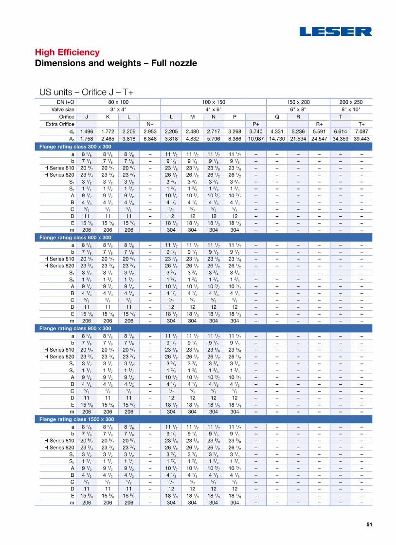
5151
High EfficiencyDimensions and weights – Full nozzle
US units – Orifice J – T+DN I+O 80 x 100 100 x 150 150 x 200 200 x 250
Valve size 3" x 4" 4" x 6" 6" x 8" 8" x 10"Orifice J K L L M N P Q R T
Extra Orifice N+ P+ R+ T+d0 1.496 1.772 2.205 2.953 2.205 2.480 2.717 3.268 3.740 4.331 5.236 5.591 6.614 7.087A0 1.758 2.465 3.818 6.848 3.818 4.832 5.796 8.386 10.987 14.730 21.534 24.547 34.359 39.443
Flange rating class 300 x 300a 8 5/6 8 5/6 8 5/6 – 11 1/7 11 1/7 11 1/7 11 1/7 – – – – – –b 7 1/8 7 1/8 7 1/8 – 9 1/5 9 1/5 9 1/5 9 1/5 – – – – – –
H Series 810 20 6/7 20 6/7 20 6/7 – 23 5/8 23 5/8 23 5/8 23 5/8 – – – – – –H Series 820 23 3/4 23 3/4 23 3/4 – 26 1/2 26 1/2 26 1/2 26 1/2 – – – – – –
S1 3 1/2 3 1/2 3 1/2 – 3 3/4 3 3/4 3 3/4 3 3/4 – – – – – –S2 1 3/7 1 3/7 1 3/7 – 1 2/3 1 2/3 1 2/3 1 2/3 – – – – – –A 9 1/2 9 1/2 9 1/2 – 10 3/7 10 3/7 10 3/7 10 3/7 – – – – – –B 4 1/3 4 1/3 4 1/3 – 4 1/3 4 1/3 4 1/3 4 1/3 – – – – – –C 5/7
5/75/7 – 5/7
5/75/7
5/7 – – – – – –D 11 11 11 – 12 12 12 12 – – – – – –E 15 5/6 15 5/6 15 5/6 – 18 1/3 18 1/3 18 1/3 18 1/3 – – – – – –m 206 206 206 – 304 304 304 304 – – – – – –
Flange rating class 600 x 300a 8 5/6 8 5/6 8 5/6 – 11 1/7 11 1/7 11 1/7 11 1/7 – – – – – –b 7 1/8 7 1/8 7 1/8 – 9 1/5 9 1/5 9 1/5 9 1/5 – – – – – –
H Series 810 20 6/7 20 6/7 20 6/7 – 23 5/8 23 5/8 23 5/8 23 5/8 – – – – – –H Series 820 23 3/4 23 3/4 23 3/4 – 26 1/2 26 1/2 26 1/2 26 1/2 – – – – – –
S1 3 1/2 3 1/2 3 1/2 – 3 3/4 3 3/4 3 3/4 3 3/4 – – – – – –S2 1 3/7 1 3/7 1 3/7 – 1 2/3 1 2/3 1 2/3 1 2/3 – – – – – –A 9 1/2 9 1/2 9 1/2 – 10 3/7 10 3/7 10 3/7 10 3/7 – – – – – –B 4 1/3 4 1/3 4 1/3 – 4 1/3 4 1/3 4 1/3 4 1/3 – – – – – –C 5/7
5/75/7 – 5/7
5/75/7
5/7 – – – – – –D 11 11 11 – 12 12 12 12 – – – – – –E 15 5/6 15 5/6 15 5/6 – 18 1/3 18 1/3 18 1/3 18 1/3 – – – – – –m 206 206 206 – 304 304 304 304 – – – – – –
Flange rating class 900 x 300a 8 5/6 8 5/6 8 5/6 – 11 1/7 11 1/7 11 1/7 11 1/7 – – – – – –b 7 1/8 7 1/8 7 1/8 – 9 1/5 9 1/5 9 1/5 9 1/5 – – – – – –
H Series 810 20 6/7 20 6/7 20 6/7 – 23 5/8 23 5/8 23 5/8 23 5/8 – – – – – –H Series 820 23 3/4 23 3/4 23 3/4 – 26 1/2 26 1/2 26 1/2 26 1/2 – – – – – –
S1 3 1/2 3 1/2 3 1/2 – 3 3/4 3 3/4 3 3/4 3 3/4 – – – – – –S2 1 3/7 1 3/7 1 3/7 – 1 2/3 1 2/3 1 2/3 1 2/3 – – – – – –A 9 1/2 9 1/2 9 1/2 – 10 3/7 10 3/7 10 3/7 10 3/7 – – – – – –B 4 1/3 4 1/3 4 1/3 – 4 1/3 4 1/3 4 1/3 4 1/3 – – – – – –C 5/7
5/75/7 – 5/7
5/75/7
5/7 – – – – – –D 11 11 11 – 12 12 12 12 – – – – – –E 15 5/6 15 5/6 15 5/6 – 18 1/3 18 1/3 18 1/3 18 1/3 – – – – – –m 206 206 206 – 304 304 304 304 – – – – – –
Flange rating class 1500 x 300a 8 5/6 8 5/6 8 5/6 – 11 1/7 11 1/7 11 1/7 11 1/7 – – – – – –b 7 1/8 7 1/8 7 1/8 – 9 1/5 9 1/5 9 1/5 9 1/5 – – – – – –
H Series 810 20 6/7 20 6/7 20 6/7 – 23 5/8 23 5/8 23 5/8 23 5/8 – – – – – –H Series 820 23 3/4 23 3/4 23 3/4 – 26 1/2 26 1/2 26 1/2 26 1/2 – – – – – –
S1 3 1/2 3 1/2 3 1/2 – 3 3/4 3 3/4 3 3/4 3 3/4 – – – – – –S2 1 3/7 1 3/7 1 3/7 – 1 2/3 1 2/3 1 2/3 1 2/3 – – – – – –A 9 1/2 9 1/2 9 1/2 – 10 3/7 10 3/7 10 3/7 10 3/7 – – – – – –B 4 1/3 4 1/3 4 1/3 – 4 1/3 4 1/3 4 1/3 4 1/3 – – – – – –C 5/7
5/75/7 – 5/7
5/75/7
5/7 – – – – – –D 11 11 11 – 12 12 12 12 – – – – – –E 15 5/6 15 5/6 15 5/6 – 18 1/3 18 1/3 18 1/3 18 1/3 – – – – – –m 206 206 206 – 304 304 304 304 – – – – – –

5252
High EfficiencyScrew Dimensions acc. to DIN EN 1092-1
The flange thickness of the inlet and outlet flanges of the Pilot Operated Safety Valve (POSV) may differ from the standard. Therefore stud-bolts for the flange connec-tions may also be longer than stated in DIN EN 1092-1. To simplify the calculation of the correct bolt length, the
quantity and sizes of the stud-bolts and nuts for the inlet and outlet flange connections are given below. The listed screw dimensions are rounded to standard dimensions. The connection flanges are based on the DIN EN 1092-1 standard.
Metric units – Orifice D – K+DN I+O 25 x 50 40 x 50 40 x 80 50 x 80
Size 1" x 2" 11/2" x 2" 11/2" x 3" 2" x 3"
API Standard orifice acc. to API 526 D E F D E F G H G H J
Extra Orifice G H J K+
d0 [mm] 11 14,7 18,4 23 11 14,7 18,4 29 23,6 29,4 35,7 23,6 29,4 38 48
A0 [mm2] 95 170 266 415 95 170 266 661 437 679 1001 437 679 1134 1810
Flange Class 150 x 150
Inle
t
Qty Hexagon screws
PN 10 –
PN 16
4 4 4 4 4 4 4 4 4 4 4 4 4 4 4
Nuts 4 4 4 4 4 4 4 4 4 4 4 4 4 4 4
Hexagon screw diameter nut size [mm] M12 M12 M12 M12 M16 M16 M16 M16 M16 M16 M16 M16 M16 M16 M16
Scr
ew
dim Raised face flange type [mm] 65 65 65 65 80 80 80 80 80 80 80 85 85 85 85
Out
let Q
ty Hexagon screws
PN 10 –
PN 16
4 4 4 4 4 4 4 4 8 8 8 8 8 8 8
Nuts 4 4 4 4 4 4 4 4 8 8 8 8 8 8 8
Hexagon screw diameter nut size [mm] M16 M16 M16 M16 M16 M16 M16 M16 M16 M16 M16 M16 M16 M16 M16
Scr
ew
dim Raised face flange type [mm] 75 75 75 75 75 75 75 75 80 80 80 80 80 80 80
Flange class 300 x 150
Inle
t
Qty Hexagon screws
PN 25 –
PN 40
4 4 4 4 4 4 4 4 4 4 4 4 4 4 4
Nuts 4 4 4 4 4 4 4 4 4 4 4 4 4 4 4
Hexagon screw diameter nut size [mm] M12 M12 M12 M12 M16 M16 M16 M16 M16 M16 M16 M16 M16 M16 M16
Scr
ew
dim Raised face flange type [mm] 65 65 65 65 80 80 80 80 80 80 80 85 85 85 85
Out
let Q
ty Hexagon screws
PN 10 –
PN 16
4 4 4 4 4 4 4 4 8 8 8 8 8 8 8
Nuts 4 4 4 4 4 4 4 4 8 8 8 8 8 8 8
Hexagon screw diameter nut size [mm] M16 M16 M16 M16 M16 M16 M16 M16 M16 M16 M16 M16 M16 M16 M16
Scr
ew
dim Raised face flange type [mm] 75 75 75 75 75 75 75 75 80 80 80 80 80 80 80
Flange class 600 x 150
Inle
t
Qty Hexagon screws
PN 10 –
PN 16
4 4 4 4 4 4 4 4 4 4 4 4 4 4 4
Nuts 4 4 4 4 4 4 4 4 4 4 4 4 4 4 4
Hexagon screw diameter nut size [mm] M12 M12 M16 M16 M16 M16 M16 M16 M16 M20 M20 M20 M20 M20 M20
Scr
ew
dim Raised face flange type [mm] 65 65 80 80 80 80 80 80 80 100 100 100 100 110 110
Out
let Q
ty Hexagon screws
PN 10 –
PN 16
4 4 4 4 4 4 8 8 8 8 8 8 8 8 8
Nuts 4 4 4 4 4 4 8 8 8 8 8 8 8 8 8
Hexagon screw diameter nut size [mm] M16 M16 M16 M16 M16 M16 M16 M16 M16 M16 M16 M16 M16 M16 M16
Scr
ew
dim Raised face flange type [mm] 75 75 75 75 75 75 80 80 80 80 80 80 80 80 80
Please note: For full nozzle design the screw lengths needs to be 30 mm longer.

5353
S
High EfficiencyScrew Dimensions acc. to DIN EN 1092-1
Metric units – Orifice J – T+DN I+O 80 x 100 100 x 150 150 x 200 200 x 250
Size 3" x 4" 4" x 6" 6" x 8" 8" x 10"
API Standard orifice acc. to API 526 J K L L M N P Q R T
Extra Orifice N+ P+ R+ T+
d0 [mm] 38 45 56 75 56 63 69 83 95 110 133 142 168 180
A0 [mm2] 1134 1590 2463 4418 2463 3117 3739 5411 7088 9503 13893 15837 22167 25447
Flange Class 150 x 150
Inle
t
Qty Hexagon screws
PN 10 –
PN 16
8 8 8 8 8 8 8 8 8 8 8 8 12 12
Nuts 8 8 8 8 8 8 8 8 8 8 8 8 12 12
Hexagon screw diameter nut size [mm] M16 M16 M16 M16 M16 M16 M16 M16 M16 M20 M20 M20 M20 M20
Scr
ew
dim Raised face flange type [mm] 90 90 90 90 100 100 100 100 100 120 120 120 130 130
Out
let Q
ty Hexagon screws PN 10 –
PN 16
8 8 8 8 8 8 8 8 8 12 12 12 12 12
Nuts 8 8 8 8 8 8 8 8 8 12 12 12 12 12
Hexagon screw diameter nut size [mm]PN 10 M16 M16 M16 M16 M20 M20 M20 M20 M20 M20 M20 M20 M20 M20
PN 16 M16 M16 M16 M16 M20 M20 M20 M20 M20 M20 M20 M20 M24 M24
Scr
ew
dim Raised face flange type [mm]
PN 10 80 80 80 80 90 90 90 90 90 110 110 110 100 100
PN 16 80 80 80 80 90 90 90 90 90 110 110 110 110 110
Flange class 300 x 150
Inle
t
Qty Hexagon screws PN 25
– PN 40
8 8 8 8 8 8 8 8 8 8 8 8 12 12
Nuts 8 8 8 8 8 8 8 8 8 8 8 8 12 12
Hexagon screw diameter nut size [mm]PN 25 M16 M16 M16 M16 M20 M20 M20 M20 M20 M24 M24 M24 M24 M24
PN 40 M16 M16 M16 M16 M20 M20 M20 M20 M20 M24 M24 M24 M24 M24
Scr
ew
dim Raised face flange type [mm]
PN 25 95 95 95 95 110 110 110 110 110 130 130 130 140 140
PN 40 95 95 95 95 110 110 110 110 110 130 130 130 150 150
Out
let Q
ty Hexagon screws PN 10 –
PN 16
8 8 8 8 8 8 8 8 8 8 8 8 8 8
Nuts 8 8 8 8 8 8 8 8 8 8 8 8 8 8
Hexagon screw diameter nut size [mm]PN 10 M16 M16 M16 M16 M20 M20 M20 M20 M20 M20 M20 M20 M20 M20
PN 16 M16 M16 M16 M16 M20 M20 M20 M20 M20 M20 M20 M20 M24 M24
Scr
ew
dim Raised face flange type [mm]
PN 10 80 80 80 80 90 90 90 90 90 110 110 110 100 100
PN 16 80 80 80 80 90 90 90 90 90 110 110 110 110 110
Flange class 600 x 150
Inle
t
Qty Hexagon screws
PN 10 –
PN 16
8 8 8 8 8 8 8 8 8 8 8 8 12 12
Nuts 8 8 8 8 8 8 8 8 8 8 8 8 12 12
Hexagon screw diameter nut size [mm] M16 M16 M16 M16 M16 M16 M16 M16 M16 M20 M20 M20 M20 M20
Scr
ew
dim Raised face flange type [mm] 90 90 90 90 100 100 100 100 100 120 120 120 130 130
Out
let
Qty Hexagon screws PN 10
–PN 16
8 8 8 8 8 8 8 8 8 12 12 12 12 12
Nuts 8 8 8 8 8 8 8 8 8 12 12 12 12 12
Hexagon screw diameter nut size [mm]PN 10 M16 M16 M16 M16 M20 M20 M20 M20 M20 M20 M20 M20 M20 M20
PN 16 M16 M16 M16 M16 M20 M20 M20 M20 M20 M20 M20 M20 M24 M24
Scr
ew
dim Raised face flange type [mm]
PN 10 80 80 80 80 90 90 90 90 90 110 110 110 100 100
PN 16 80 80 80 80 90 90 90 90 90 110 110 110 110 110
Outlet
Inlet
S
Please note: For full nozzle design the screw lengths needs to be 30 mm longer.

5454
High EfficiencyScrew Dimensions acc. to DIN EN 1092-1
Metric units – Orifice D – K+DN I+O 25 x 50 40 x 50 40 x 80 50 x 80
Size 1" x 2" 11/2" x 2" 11/2" x 3" 2" x 3"
API Standard orifice acc. to API 526 D E F D E F G H G H J
Extra Orifice G H J K+
d0 [mm] 11 14,7 18,4 23 11 14,7 18,4 29 23,6 29,4 35,7 23,6 29,4 38 48
A0 [mm2] 95 170 266 415 95 170 266 661 437 679 1001 437 679 1134 1810
Flange Class 900 x 300
Inle
t
Qty Hexagon screws
PN 40
4 4 4 4 4 4 4 4 4 4 4 4 4 4 4
Nuts 4 4 4 4 4 4 4 4 4 4 4 4 4 4 4
Hexagon screw diameter nut size [mm] M12 M12 M12 M12 M16 M16 M16 M16 M16 M16 M16 M16 M16 M16 M16
Scr
ew
dim Raised face flange type [mm] 80 80 80 80 90 90 90 90 90 90 90 100 100 100 100
Inle
t
Qty Hexagon screws
PN 63
4 4 4 4 4 4 4 4 4 4 4 4 4 4 4
Nuts 4 4 4 4 4 4 4 4 4 4 4 4 4 4 4
Hexagon screw diameter nut size [mm] M16 M16 M16 M16 M20 M20 M20 M20 M20 M20 M20 M20 M20 M20 M20
Scr
ew
dim Raised face flange type [mm] 90 90 90 90 100 100 100 100 100 100 100 110 110 110 110
Inle
t
Qty Hexagon screws
PN 100
4 4 4 4 4 4 4 4 4 4 4 4 4 4 4
Nuts 4 4 4 4 4 4 4 4 4 4 4 4 4 4 4
Hexagon screw diameter nut size [mm] M16 M16 M16 M16 M20 M20 M20 M20 M20 M20 M20 M24 M24 M24 M24
Scr
ew
dim Raised face flange type [mm] 90 90 90 90 100 100 100 100 100 100 100 120 120 120 120
Inle
t
Qty Hexagon screws
PN 160
4 4 4 4 4 4 4 4 4 4 4 4 4 4 4
Nuts 4 4 4 4 4 4 4 4 4 4 4 4 4 4 4
Hexagon screw diameter nut size [mm] M16 M16 M16 M16 M20 M20 M20 M20 M20 M20 M20 M24 M24 M24 M24
Scr
ew
dim Raised face flange type [mm] 90 90 90 90 110 110 110 110 110 110 110 120 120 120 120
Out
let Q
ty Hexagon screws
PN 40
4 4 4 4 4 4 4 4 8 8 8 8 8 8 8
Nuts 4 4 4 4 4 4 4 4 8 8 8 8 8 8 8
Hexagon screw diameter nut size [mm] M16 M16 M16 M16 M16 M16 M16 M16 M16 M16 M16 M16 M16 M16 M16
Scr
ew
dim Raised face flange type [mm] 80 80 80 80 85 85 85 85 90 90 90 90 90 90 90
Flange class 1500 x 300
Inle
t
Qty Hexagon screws
PN 36
4 4 4 4 4 4 4 4 4 4 4 8 8 8 8
Nuts 4 4 4 4 4 4 4 4 4 4 4 8 8 8 8
Hexagon screw diameter nut size [mm] M20 M20 M20 M20 M24 M24 M24 M24 M24 M24 M24 M24 M24 M24 M24
Scr
ew
dim Raised face flange type [mm] 100 100 100 100 120 120 120 120 120 120 120 130 130 130 130
Out
let Q
ty Hexagon screws
PN 10 –
PN 16
4 4 4 4 4 4 4 4 8 8 8 8 8 8 8
Nuts 4 4 4 4 4 4 4 4 8 8 8 8 8 8 8
Hexagon screw diameter nut size [mm] M16 M16 M16 M16 M16 M16 M16 M16 M16 M16 M16 M16 M16 M16 M16
Scr
ew
dim Raised face flange type [mm] 80 80 80 80 85 85 85 85 90 90 90 90 90 90 90
Please note: For full nozzle design the screw lengths needs to be 30 mm longer.

5555
High EfficiencyScrew Dimensions acc. to DIN EN 1092-1
Metric units – Orifice J – T+DN I+O 80 x 100 100 x 150 150 x 200 200 x 250
Size 3" x 4" 4" x 6" 6" x 8" 8" x 10"
API Standard orifice acc. to API 526 J K L L M N P Q R T
Extra Orifice N+ P+ R+ T+
d0 [mm] 38 45 56 75 56 63 69 83 95 110 133 142 168 180
A0 [mm2] 1134 1590 2463 4418 2463 3117 3739 5411 7088 9503 13893 15837 22167 25447
Flange Class 900 x 300
Inle
t
Qty Hexagon screws
PN 40
8 8 8 8 8 8 8 8 8
Nuts 8 8 8 8 8 8 8 8 8
Hexagon screw diameter nut size [mm] M16 M16 M16 M16 M20 M20 M20 M20 M20
Scr
ew
dim Raised face flange type [mm] 110 110 110 110 130 130 130 130 130
Inle
t
Qty Hexagon screws
PN 63
8 8 8 8 8 8 8 8 8
Nuts 8 8 8 8 8 8 8 8 8
Hexagon screw diameter nut size [mm] M20 M20 M20 M20 M24 M24 M24 M24 M24
Scr
ew
dim Raised face flange type [mm] 120 120 120 120 140 140 140 140 140
Inle
t
Qty Hexagon screws
PN 100
8 8 8 8 8 8 8 8 8
Nuts 8 8 8 8 8 8 8 8 8
Hexagon screw diameter nut size [mm] M24 M24 M24 M24 M27 M27 M27 M27 M27
Scr
ew
dim Raised face flange type [mm] 130 130 130 130 150 150 150 150 150
Inle
t
Qty Hexagon screws
PN 160
8 8 8 8 8 8 8 8 8
Nuts 8 8 8 8 8 8 8 8 8
Hexagon screw diameter nut size [mm] M24 M24 M24 M24 M27 M27 M27 M27 M27
Scr
ew
dim Raised face flange type [mm] 140 140 140 140 150 150 150 150 150
Out
let Q
ty Hexagon screws
PN 40
8 8 8 8 8 8 8 8 8
Nuts 8 8 8 8 8 8 8 8 8
Hexagon screw diameter nut size [mm] M20 M20 M20 M20 M24 M24 M24 M24 M24
Scr
ew
dim Raised face flange type [mm] 100 100 100 100 120 120 120 120 120
Flange class 1500 x 300
Inle
t
Qty Hexagon screws
PN 250
8 8 8 8 8 8 8 8 8
Nuts 8 8 8 8 8 8 8 8 8
Hexagon screw diameter nut size [mm] M27 M27 M27 M27 M30 M30 M30 M30 M30
Scr
ew
dim Raised face flange type [mm] 150 150 150 150 170 170 170 170 170
Out
let Q
ty Hexagon screws
PN 40
8 8 8 8 8 8 8 8 8
Nuts 8 8 8 8 8 8 8 8 8
Hexagon screw diameter nut size [mm] M20 M20 M20 M20 M24 M24 M24 M24 M24
Scr
ew
dim Raised face flange type [mm] 100 100 100 100 120 120 120 120 120
Please note: For full nozzle design the screw lengths needs to be 30 mm longer.

5656
High EfficiencyScrew Dimensions acc. to ASME B16.5
The flange thickness of the inlet and outlet flanges of the Pilot Operated Safety Valve (POSV) may differ from the standard. Therefore stud-bolts for the flange con-nections may also be longer than stated in ASME B16.5. To simplify the calculation of the correct bolt length, the
quantity and sizes of the stud-bolts and nuts for the inlet and outlet flange connections are given below. The listed screw dimensions are rounded to standard dimensions. The connection flanges are based on the ASME B16.5 standard.
US units – Orifice D – K+DN I+O 25 x 50 40 x 50 40 x 80 50 x 80
Size 1" x 2" 11/2" x 2" 11/2" x 3" 2" x 3"
API Standard orifice acc. to API 526 D E F D E F G H G H J
Extra Orifice G H J K+
d0 [inch] 0.433 0.579 0.724 0.906 0.433 0.579 0.724 1.142 0.929 1.157 1.406 0.929 1.157 1.496 1.890
A0 [inch2] 0.147 0.264 0.412 0.644 0.147 0.264 0.412 1.024 0.678 1.052 1.552 0.678 1.052 1.758 2.805
Flange class 150 x 150
Inle
t
Qty Stud bolts 4 4 4 4 4 4 4 4 4 4 4 4 4 4 4
Nuts 8 8 8 8 8 8 8 8 8 8 8 8 8 8 8
Stud bolt diameter nut size [inch] 1/21/2
1/21/2
1/21/2
1/21/2
1/21/2
1/25/8
5/85/8
5/8
Bol
t di
m Raised face flange type [inch] 3 1/4 3 1/4 3 1/4 3 1/4 3 1/2 3 1/2 3 1/2 3 1/2 3 1/2 3 1/2 3 1/2 4 4 4 4
Ring type joint flange [inch] 3 1/4 3 1/4 3 1/4 3 1/4 3 1/2 3 1/2 3 1/2 3 1/2 3 1/2 3 1/2 3 1/2 4 1/4 4 1/4 4 1/4 4 1/4
Out
let Q
ty Stud bolts 4 4 4 4 4 4 4 4 4 4 4 4 4 4 4
Nuts 8 8 8 8 8 8 8 8 8 8 8 8 8 8 8
Bolt size [inch] 5/85/8
5/85/8
5/85/8
5/85/8
5/85/8
5/85/8
5/85/8
5/8
Bol
t di
m Raised face flange type [inch] 3 3/4 3 3/4 3 3/4 3 3/4 3 3/4 3 3/4 3 3/4 3 3/4 4 4 4 4 4 4 4
Ring type joint flange [inch] 4 4 4 4 4 4 4 4 4 1/4 4 1/4 4 1/4 4 1/4 4 1/4 4 1/4 4 1/4
Flange class 300 x 150
Inle
t
Qty Stud bolts 4 4 4 4 4 4 4 4 4 4 4 8 8 8 8
Nuts 8 8 8 8 8 8 8 8 8 8 8 16 16 16 16
Bolt size [inch] 5/85/8
5/85/8
3/43/4
3/43/4
3/43/4
3/45/8
5/85/8
5/8
Bol
t di
m Raised face flange type [inch] 3 3/4 3 3/4 3 3/4 3 3/4 4 1/4 4 1/4 4 1/4 4 1/4 4 1/4 4 1/4 4 1/4 4 1/4 4 1/4 4 1/4 4 1/4
Ring type joint flange [inch] 3 3/4 3 3/4 3 3/4 3 3/4 4 1/2 4 1/2 4 1/2 4 1/2 4 1/2 4 1/2 4 1/2 4 1/4 4 1/4 4 1/4 4 1/4
Out
let Q
ty Stud bolts 4 4 4 4 4 4 4 4 4 4 4 4 4 4 4
Nuts 8 8 8 8 8 8 8 8 8 8 8 8 8 8 8
Bolt size [inch] 5/85/8
5/85/8
5/85/8
5/85/8
5/85/8
5/85/8
5/85/8
5/8
Bol
t di
m Raised face flange type [inch] 3 3/4 3 3/4 3 3/4 3 3/4 3 3/4 3 3/4 3 3/4 3 3/4 4 4 4 4 4 4 4
Ring type joint flange [inch] 4 4 4 4 4 4 4 4 4 1/4 4 1/4 4 1/4 4 1/4 4 1/4 4 1/4 4 1/4
Flange class 600 x 150
Inle
t
Qty Stud bolts 4 4 4 4 4 4 4 4 4 4 4 8 8 8 8
Nuts 8 8 8 8 8 8 8 8 8 8 8 16 16 16 16
Bolt size [inch] 5/85/8
5/85/8
3/43/4
3/43/4
3/43/4
3/45/8
5/85/8
5/8
Bol
t di
m Raised face flange type [inch] 4 4 4 4 4 3/4 4 3/4 4 3/4 4 3/4 4 3/4 4 3/4 4 3/4 4 1/2 4 1/2 4 1/2 4 1/2
Ring type joint flange [inch] 4 4 4 4 4 3/4 4 3/4 4 3/4 4 3/4 4 3/4 4 3/4 4 3/4 4 3/4 4 3/4 4 3/4 4 3/4
Out
let Q
ty Stud bolts 4 4 4 4 4 4 4 4 4 4 4 4 4 4 4
Nuts 8 8 8 8 8 8 8 8 8 8 8 8 8 8 8
Bolt size [inch] 5/85/8
5/85/8
5/85/8
5/85/8
5/85/8
5/85/8
5/85/8
5/8
Bol
t di
m Raised face flange type [inch] 3 3/4 3 3/4 3 3/4 3 3/4 3 3/4 3 3/4 3 3/4 3 3/4 4 4 4 4 4 4 4
Ring type joint flange [inch] 4 4 4 4 4 4 4 4 4 1/4 4 1/4 4 1/4 4 1/4 4 1/4 4 1/4 4 1/4
Please note: For full nozzle design the screw lengths needs to be 1 1/4 inch longer.

5757
S
High EfficiencyScrew Dimensions acc. to ASME B16.5
US units – Orifice J – T+DN I+O 80 x 100 100 x 150 150 x 200 200 x 250
Size 3" x 4" 4" x 6" 6" x 8" 8" x 10"
API Standard orifice acc. to API 526 J K L L M N P Q R T
Extra Orifice N+ P+ R+ T+
d0 [inch] 1.496 1.772 2.205 2.953 2.205 2.480 2.717 3.268 3.740 4.331 5.236 5.591 6.614 7.087
A0 [inch2] 1.758 2.465 3.818 6.848 3.818 4.832 5.796 8.386 10.987 14.730 21.534 24.547 34.359 39.443
Flange class 150 x 150
Inle
t
Qty Stud bolts 4 4 4 4 8 8 8 8 8 8 8 8 8 8
Nuts 8 8 8 8 16 16 16 16 16 16 16 16 16 16
Stud bolt diameter nut size [inch] 5/85/8
5/85/8
5/85/8
5/85/8
5/83/4
3/43/4
3/43/4
Bol
t di
m Raised face flange type [inch] 41/2 41/2 41/2 41/2 43/4 43/4 43/4 43/4 43/4 51/2 51/2 51/2 6 6
Ring type joint flange [inch] 43/4 43/4 43/4 43/4 5 5 5 5 5 53/4 53/4 53/4 61/4 61/4
Out
let Q
ty Stud bolts 8 8 8 8 8 8 8 8 8 8 8 8 12 12
Nuts 16 16 16 16 16 16 16 16 16 16 16 16 24 24
Bolt size [inch] 5/85/8
5/85/8
3/43/4
3/43/4
3/43/4
3/43/4
7/87/8
Bol
t di
m Raised face flange type [inch] 4 4 4 4 41/2 41/2 41/2 41/2 41/2 51/4 51/4 51/4 51/4 51/4
Ring type joint flange [inch] 41/4 41/4 41/4 41/4 43/4 43/4 43/4 43/4 43/4 51/2 51/2 51/2 51/2 51/2
Flange class 300 x 150
Inle
t
Qty Stud bolts 8 8 8 8 8 8 8 8 8 12 12 12 12 12
Nuts 16 16 16 16 16 16 16 16 16 24 24 24 24 24
Bolt size [inch] 3/43/4
3/43/4
3/43/4
3/43/4
3/43/4
3/43/4
7/87/8
Bol
t di
m Raised face flange type [inch] 5 5 5 5 5 1/2 5 1/2 5 1/2 5 1/2 5 1/2 6 6 6 7 7
Ring type joint flange [inch] 5 1/2 5 1/2 5 1/2 5 1/2 5 3/4 5 3/4 5 3/4 5 3/4 5 3/4 6 1/4 6 1/4 6 1/4 7 1/4 7 1/4
Out
let Q
ty Stud bolts 8 8 8 8 8 8 8 8 8 8 8 8 12 12
Nuts 16 16 16 16 16 16 16 16 16 16 16 16 24 24
Bolt size [inch] 5/85/8
5/85/8
3/43/4
3/43/4
3/43/4
3/43/4
7/87/8
Bol
t di
m Raised face flange type [inch] 4 4 4 4 4 1/2 4 1/2 4 1/2 4 1/2 4 1/2 5 1/4 5 1/4 5 1/4 5 1/4 5 1/4
Ring type joint flange [inch] 4 1/4 4 1/4 4 1/4 4 1/4 4 3/4 4 3/4 4 3/4 4 3/4 4 3/4 5 1/2 5 1/2 5 1/2 5 1/2 5 1/2
Flange class 600 x 150
Inle
t
Qty Stud bolts 8 8 8 8 8 8 8 8 8 8 8 8 12 12
Nuts 16 16 16 16 16 16 16 16 16 24 24 24 24 24
Bolt size [inch] 3/43/4
3/43/4
7/87/8
7/87/8
7/8 1 1 1 1 1/8 1 1/8
Bol
t di
m Raised face flange type [inch] 5 1/2 5 1/2 5 1/2 5 1/2 6 1/4 6 1/4 6 1/4 6 1/4 6 1/4 7 1/2 7 1/2 7 1/2 8 1/2 8 1/2
Ring type joint flange [inch] 5 1/2 5 1/2 5 1/2 5 1/2 6 1/2 6 1/2 6 1/2 6 1/2 6 1/2 7 1/2 7 1/2 7 1/2 8 1/2 8 1/2
Out
let Q
ty Stud bolts 8 8 8 8 8 8 8 8 8 8 8 8 12 12
Nuts 16 16 16 16 16 16 16 16 16 16 16 16 24 24
Bolt size [inch] 5/85/8
5/85/8
3/43/4
3/43/4
3/43/4
3/43/4
7/87/8
Bol
t di
m Raised face flange type [inch] 4 4 4 4 4 1/2 4 1/2 4 1/2 4 1/2 4 1/2 5 1/4 5 1/4 5 1/4 5 1/4 5 1/4
Ring type joint flange [inch] 4 1/4 4 1/4 4 1/4 4 1/4 4 3/4 4 3/4 4 3/4 4 3/4 4 3/4 5 1/2 5 1/2 5 1/2 5 1/2 5 1/2
Outlet
Inlet
S
Please note: For full nozzle design the screw lengths needs to be 1 1/4 inch longer.

5858
High EfficiencyScrew Dimensions acc. to ASME B16.5
US units – Orifice D – K+DN I+O 25 x 50 40 x 50 40 x 80 50 x 80
Size 1" x 2" 11/2" x 2" 11/2" x 3" 2" x 3"
API Standard orifice acc. to API 526 D E F D E F G H G H J
Extra Orifice G H J K+
d0 [inch] 0.433 0.579 0.724 0.906 0.433 0.579 0.724 1.142 0.929 1.157 1.406 0.929 1.157 1.496 1.890
A0 [inch2] 0.147 0.264 0.412 0.644 0.147 0.264 0.412 1.024 0.678 1.052 1.552 0.678 1.052 1.758 2.805
Flange class 900 x 300
Inle
t
Qty Stud bolts 4 4 4 4 4 4 4 4 4 4 4 8 8 8 8
Nuts 8 8 8 8 8 8 8 8 8 8 8 16 16 16 16
Stud bolt diameter nut size [inch] 1 1 1 1 1 1/8 1 1/8 1 1/8 1 1/8 1 1/8 1 1/8 1 1/8 1 1 1 1
Bol
t di
m Raised face flange type [inch] 5 3/4 5 3/4 5 3/4 5 3/4 6 1/2 6 1/2 6 1/2 6 1/2 6 1/2 6 1/2 6 1/2 6 6 6 6
Ring type joint flange [inch] 6 6 6 6 6 3/4 6 3/4 6 3/4 6 3/4 6 3/4 6 3/4 6 3/4 6 1/4 6 1/4 6 1/4 6 1/4
Out
let Q
ty Stud bolts 8 8 8 8 8 8 8 8 8 8 8 8 8 8 8
Nuts 16 16 16 16 16 16 16 16 16 16 16 16 16 16 16
Bolt size [inch] 3/43/4
3/43/4
3/43/4
3/43/4
7/87/8
7/87/8
7/87/8
7/8
Bol
t di
m Raised face flange type [inch] 4 4 4 4 4 4 4 4 4 1/2 4 1/2 4 1/2 4 1/2 4 1/2 4 1/2 4 1/2
Ring type joint flange [inch] 4 1/4 4 1/4 4 1/4 4 1/4 4 1/2 4 1/2 4 1/2 4 1/2 5 5 5 5 5 5 5
Flange class 1500 x 300
Inle
t
Qty Stud bolts 4 4 4 4 4 4 4 4 4 4 4 8 8 8 8
Nuts 8 8 8 8 8 8 8 8 8 8 8 16 16 16 16
Bolt size [inch] 1 1 1 1 1 1/4 1 1/4 1 1/4 1 1/4 1 1/4 1 1/4 1 1/4 1 1 1 1
Bol
t di
m Raised face flange type [inch] 5 3/4 5 3/4 5 3/4 5 3/4 6 1/4 6 1/4 6 1/4 6 1/4 6 1/2 6 1/2 6 1/2 6 1/2 6 1/2 6 1/2 6 1/2
Ring joint flange [inch] 6 6 6 6 6 1/2 6 1/2 6 1/2 6 1/2 6 3/4 6 3/4 6 3/4 6 3/4 6 3/4 6 3/4 6 3/4
Out
let Q
ty Stud bolts 8 8 8 8 8 8 8 8 8 8 8 8 8 8 8
Nuts 16 16 16 16 16 16 16 16 16 16 16 16 16 16 16
Bolt size [inch] 3/43/4
3/43/4
3/43/4
3/43/4
7/87/8
7/87/8
7/87/8
7/8
Bol
t di
m Raised face flange type [inch] 4 4 4 4 4 4 4 4 4 1/2 4 1/2 4 1/2 4 1/2 4 1/2 4 1/2 4 1/2
Ring type joint flange [inch] 4 1/4 4 1/4 4 1/4 4 1/4 4 1/2 4 1/2 4 1/2 4 1/2 5 5 5 5 5 5 5
Please note: For full nozzle design the screw lengths needs to be 11/4 inch longer.

5959
High EfficiencyScrew Dimensions acc. to ASME B16.5
US units – Orifice J – T+DN I+O 80 x 100 100 x 150 150 x 200 200 x 250
Size 3" x 4" 4" x 6" 6" x 8" 8" x 10"
API Standard orifice acc. to API 526 J K L L M N P Q R T
Extra Orifice N+ P+ R+ T+
d0 [inch] 1.496 1.772 2.205 2.953 2.205 2.480 2.717 3.268 3.740 4.331 5.236 5.591 6.614 7.087
A0 [inch2] 1.758 2.465 3.818 6.848 3.818 4.832 5.796 8.386 10.987 14.730 21.534 24.547 34.359 39.443
Flange class 900 x 300
Inle
t
Qty Stud bolts 8 8 8 8 8 8 8 8 8
Nuts 16 16 16 16 16 16 16 16 16
Stud bolt diameter nut size [inch] 1 1/4 1 1/4 1 1/4 1 1/4 1 1/4 1 1/4 1 1/4 1 1/4 1 1/4
Bol
t di
m Raised face flange type [inch] 7 7 7 7 8 1/4 8 1/4 8 1/4 8 1/4 8 1/4
Ring type joint flange [inch] 7 1/4 7 1/4 7 1/4 7 1/4 8 1/2 8 1/2 8 1/2 8 1/2 8 1/2
Out
let Q
ty Stud bolts 8 8 8 8 12 12 12 12 12
Nuts 16 16 16 16 24 24 24 24 24
Bolt size [inch] 7/87/8
7/87/8
7/87/8
7/87/8
7/8
Bol
t di
m Raised face flange type [inch] 4 3/4 4 3/4 4 3/4 4 3/4 5 1/2 5 1/2 5 1/2 5 1/2 5 1/2
Ring type joint flange [inch] 5 5 5 5 6 6 6 6 6
Flange class 1500 x 300
Inle
t
Qty Stud bolts 8 8 8 8 8 8 8 8 8
Nuts 16 16 16 16 16 16 16 16 16
Bolt size [inch] 1 1/4 1 1/4 1 1/4 1 1/4 1 3/8 1 3/8 1 3/8 1 3/8 1 3/8
Bol
t di
m Raised face flange type [inch] 8 8 8 8 9 9 9 9 9
Ring type joint flange [inch] 8 1/4 8 1/4 8 1/4 8 1/4 9 1/4 9 1/4 9 1/4 9 1/4 9 1/4
Out
let Q
ty Stud bolts 8 8 8 8 12 12 12 12 12
Nuts 16 16 16 16 24 24 24 24 24
Bolt size [inch] 7/87/8
7/87/8
7/87/8
7/87/8
7/8
Bol
t di
m Raised face flange type [inch] 4 3/4 4 3/4 4 3/4 4 3/4 5 1/2 5 1/2 5 1/2 5 1/2 5 1/2
Ring type joint flange [inch] 5 5 5 5 6 6 6 6 6
Please note: For full nozzle design the screw lengths needs to be 11/4 inch longer.

6060
Remote SensingR28
Soft sealing POSV completeO-ring disc, Piston guide, Seat, Tubing, CoverR05: EPDMR06: FFKMR04: FKM (Standard)
Field test connectionR26
Blowdownadjusted to x%R44
Drain holeJ19: G1/2
R48: NPT 1/2"
Pilot lifting deviceR25
Pilot test gagR33
Backflow preventer (Standard)
Prevents return flow of the medium from the discharge into the system to be secured.
Set pressure testing with external test medium.
Mechanical lifting of pilot for veri-fication of POSV operation.
Filter to prevent plugging of the pilot.
Blocking of operation in case of required hydrostatic testing of vessel.
Functional test of main valve piston.
Blowdown adjusted: Closing pressure difference as a fixed value bet-ween 3 – 15%. Standard adjustment between 3 – 7%.
Manual blowdownR27 to atmosphereR24 into main valve outlet
Pilot supply filterR30
NACE sour gas applicationR70
Main valve discR71 metal sealing
High EfficiencyAvailable options
*Actual operating pressure sensed to pilot. No influence of inlet pressure losses, stable function of POSV.
Full nozzleR69
Flange rating class300 x 300, 600 x 300H65, H67
ED-Design(Explosive decompression)R3A (FKM)
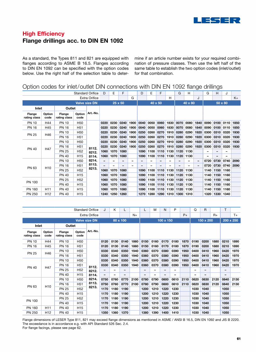
6161
High EfficiencyFlange drillings acc. to DIN EN 1092
Standard Orifice J K L L M N P Q R T
Extra Orifice N+ P+ R+ T+
Valve size DN 80 x 100 100 x 150 150 x 200 200 x 250
Inlet Outlet
Art.-No.Flange rating class
Option code
Flange rating class
Option code
PN 10 H44 PN 10 H50
8112.8212.8114.8214.8113.8213.
0120 0130 0140 1860 0150 0160 0170 0180 1870 0190 0200 1880 0210 1890
PN 16 H45 PN 16 H51 0120 0130 0140 1860 0150 0160 0170 0180 1870 0190 0200 1880 0210 1890
PN 25 H46PN 10 H50 0330 0340 0350 1940 0360 0370 0380 0390 1950 0400 0410 1960 0420 1970
PN 16 H51 0330 0340 0350 1940 0360 0370 0380 0390 1950 0400 0410 1960 0420 1970
PN 40 H47
PN 10 H50 0330 0340 0350 1940 0360 0370 0380 0390 1950 0400 0410 1960 0420 1970
PN 16 H51 0330 0340 0350 1940 0360 0370 0380 0390 1950 0400 0410 1960 0420 1970
PN 25 H52 – – – – – – – – – –
PN 40 H15 – – – – – – – – – –
PN 63 H10
PN 10 H50 0750 0760 0770 2100 0780 0790 0800 0810 2110 0820 0830 2120 0840 2130
PN 16 H51 0750 0760 0770 2100 0780 0790 0800 0810 2110 0820 0830 2120 0840 2130
PN 25 H52 1170 1180 1190 1200 1210 1220 1230 1030 1040 1050
PN 40 H15 1170 1180 1190 1200 1210 1220 1230 1030 1040 1050
PN 100PN 25 H52 1170 1180 1190 1200 1210 1220 1230 1030 1040 1050
PN 40 H15 1170 1180 1190 1200 1210 1220 1230 1030 1040 1050
PN 160 H11 PN 40 H15 1170 1180 1190 1200 1210 1220 1230 1030 1040 1050
PN 250 H12 PN 40 H15 1350 1360 1370 1380 1390 1400 1410 1030 1040 1050
Standard Orifice D E F D E F G H G H JExtra Orifice G H J K+
Valve size DN 25 x 50 40 x 50 40 x 80 50 x 80
Inlet OutletArt.-No.Flange
rating classOption code
Flange rating class
Option code
PN 10 H44 PN 10 H50
8112.8212.8114.8214.8113.8213.
0220 0230 0240 1900 0040 0050 0060 1830 0070 0080 1840 0090 0100 0110 1850
PN 16 H45 PN 16 H51 0220 0230 0240 1900 0040 0050 0060 1830 0070 0080 1840 0090 0100 0110 1850
PN 25 H46PN 10 H50 0220 0230 0240 1900 0250 0260 0270 1910 0280 0290 1920 0300 0310 0320 1930
PN 16 H51 0220 0230 0240 1900 0250 0260 0270 1910 0280 0290 1920 0300 0310 0320 1930
PN 40 H47
PN 10 H50 0220 0230 0240 1900 0250 0260 0270 1910 0280 0290 1920 0300 0310 0320 1930
PN 16 H51 0220 0230 0240 1900 0250 0260 0270 1910 0280 0290 1920 0300 0310 0320 1930
PN 25 H52 1060 1070 1080 1090 1100 1110 1130 1120 1130 – – –
PN 40 H15 1060 1070 1080 1090 1100 1110 1130 1120 1130 – – –
PN 63 H10
PN 10 H50 – – – – – – – – – – – 0720 0730 0740 2090
PN 16 H51 – – – – – – – – – – – 0720 0730 0740 2090
PN 25 H52 1060 1070 1080 1090 1100 1110 1130 1120 1130 1140 1150 1160
PN 40 H15 1060 1070 1080 1090 1100 1110 1130 1120 1130 1140 1150 1160
PN 100PN 25 H52 1060 1070 1080 1090 1100 1110 1130 1120 1130 1140 1150 1160
PN 40 H15 1060 1070 1080 1090 1100 1110 1130 1120 1130 1140 1150 1160
PN 160 H11 PN 40 H15 1060 1070 1080 1090 1100 1110 1130 1120 1130 1140 1150 1160
PN 250 H12 PN 40 H15 1240 1250 1260 1270 1280 1290 1310 1300 1310 1320 1330 1340
Option codes for inlet/outlet DIN connections with DIN EN 1092 flange drillings
As a standard, the Types 811 and 821 are equipped with flanges according to ASME B 16.5. Flanges according to DIN EN 1092 can be specified with the option codes below. Use the right half of the selection table to deter-
mine if an article number exists for your required combi-nation of pressure classes. Then use the left half of the same table to establish the two option codes (inlet/outlet) for that combination.
Flange dimensions of LESER Type 811, 821 may exceed flange dimensions as mentioned in ASME / ANSI B 16.5, DIN EN 1092 and JIS B 2220. The exceedance is in accordance e.g. with API Standard 526 Sec. 2.4.For flange facings, please see page 62.

6262
High EfficiencyFlange facings
The following table shows the various specifications for flange facings according to ASME B16.5 or DIN EN.
Acc. to DIN EN 1092
Flange facingInlet Outlet Note
PN 10 – PN 40 PN 10 – PN 40 (Rz-data according to DIN EN 1092 in µm)
Raised faceForm B1 * * Facing: Rz = 12.5 – 50Form B2 L36 L38 Facing: Rz = 3.2 – 12.5
Ste
el fl
ange
s on
ly
Tongue face C1) H94 H92Groove face D1) H93 H91Male face E H96 H98Female face F H97 H99O-ring male face G J01 J02O-ring female face H J03 J04
1) LESER manufactures the groove at flanged valves by milling. If you require a turned surface in the bottom of the groove according to DIN 2512 and/or DIN EN 1092-1 an additional option code is necessary: “S01: bottom of the groove turned.” Groove and tongue for PN160 flanges refer to DIN2512/ WI 3313.32.
2) Smooth finish is not defined in the effective standards.
Note: Flange drillings and facings meet always the requirements of mentioned flange standards. Flange thickness and outer diameter may vary from flange standard.
Acc. to ASME B16.5
Smooth Finish2) Serrated Finish RTJ-groove
Inlet Outlet Inlet OutletInlet Outlet
DN / NPS CL150 CL300 CL600 CL150
Type Inlet Outlet Option code Option code Option code
811, 821 All All L52 L53 * * H62 H63
Flange facings

6363
UV
High EfficiencyApprovals – Series 810 and 820
LESER Pilot Operated Safety Valves can be used world-wide, as they comply with the following inter national codes and standards:
• United States: UV-Stamp acc. to ASME Section VIII Division 1, National Board certified capacities for steam, gases and liquids
• European Community: CE marking as per Pressure Equipment Directive 97/23/EC and EN ISO 4126-4
• Germany: VdTUEV approval as per Pressure Equipment Directive, EN ISO 4126-4, VdTUEV – Merkblatt SV 100/1
The design, manufacture and marking of LESER’s Pilot Operated Safety Valves also complies with the following regulations:
ASME PTC 25, ASME-Code Sec. II, ASME B16.34 and ASME B16.5, API Std. 527, API RP 576, EN ISO 4126-7, EN 12266-1/-2, EN 1092 part I and II
ApprovalsSerie 810 Serie 820
United States Coefficient of discharge K
ASME Sec. VIII Div. 1Steam
Approval No. Not approved M37280
Coefficient of discharge K Not approved 0.82
GasApproval No. M37268
Coefficient of discharge K 0.82 0.82
LiquidApproval No. Not approved M37268
Coefficient of discharge K Not approved 0.689
European Community Coefficient of discharge Kdr
DIN EN ISO 4126-4 Approval No. 07 202 1321 Z 0038/9/01
S/G G: 0.82 S/G: 0.82
L Not approved 0.69
Germany Coefficient of discharge w
AD 2000-Merkblatt A2 Approval No. TÜV SV 10-1126
S/G G: 0.82 S/G: 0.82
L Not approved 0.69
Canada Coefficient of discharge K
Canada: CRN Approval No. For current approval no. see www.leser.com
Steam Coefficient of discharge K Not approved 0.82
Gas Coefficient of discharge K 0.82 0.82
Liquid Coefficient of discharge K Not approved 0.689
China Coefficient of discharge w
AQSIQ Approval No. For current approval no. see www.leser.com
S/G G: 0.82 S/G: 0.82
L Not approved 0.69
Russia Coefficient of discharge w
TR / TRN Approval No. For current approval no. see www.leser.com
S/G G: 0.82 S/G: 0.82
L Not approved 0.69

6464
Spare parts kits – Type 811 – Pop ActionValve size 1" x 2" 1 1/2" x 2" 1 1/2" x 3" 2" x 3"
Standard Orifice acc. to API 526
D E F D E F G H G H J
Extra Orifice G H J K+
Soft sealing FKM
Art.-No.
Main valve 5012. 1130 1131 1132 1133
Pilot 2.5 – 102 bar 36 – 1480 psig
5012.1163 1163 1163 1163
Soft sealing EPDM
Art.-No.
Main valve 5012. 1138 1139 1140 1141
Pilot 2.5 – 102 bar 36 – 1480 psig
5012.1164 1164 1164 1164
Soft sealing FFKM
Art.-No.
Main valve 5012. 1146 1147 1148 1149
Pilot 2.5 – 102 bar 36 – 1480 psig
5012.1165 1165 1165 1165
Materials – Main valveItem Component Material Quantity
Lubricant Molykote D 1
Lubricant oil Halocarbon oil 56S 1
6.3, 7.3, 60, 61, 63, 67 O-ring FKM / EPDM / FFKM 6
6.4 Backup ring PTFE 1
6.5 Guide ring PTFE-carbon filler 2
10 Parallel pin 1.4310 1
58 Screw 1.4310 2
62 Backup ring PTFE 1
The spare part kit provides all spare parts which are recommended by LESER to be replaced during rework of a safety valve.
High EfficiencySpare parts kits

6565
Spare parts kits – Type 811 – Pop ActionValve size 3" x 4" 4" x 6" 6" x 8" 8" x 10"
Standard Orifice acc. to API 526
J K L L M N P Q R T
Extra Orifice N+ P+ R+ T+
Soft sealing FKM
Art.-No.
Main valve 5012. 1134 1135 1136 1137
Pilot 2.5 – 102 bar 36 – 1480 psig
5012.1163 1163 1163 1163
Soft sealing EPDM
Art.-No.
Main valve 5012. 1142 1143 1144 1145
Pilot 2.5 – 102 bar 36 – 1480 psig
5012.1164 1164 1164 1164
Soft sealing FFKM
Art.-No.
Main valve 5012. 1150 1151 1152 1153
Pilot 2.5 – 102 bar 36 – 1480 psig
5012.1165 1165 1165 1165
Materials – Type 811 – Pop ActionItem Component Material Quantity
Lubricant Molykote D 1
Lubricant oil Halocarbon oil 56S 1
64 Bug screen Plastic 1
15 Plunger 1.4404 / 316L 1
6, 7, 8 O-ring Field test connection FKM / EPDM / FFKM 3
24.4, 24.5, 24.6 O-ring Manifold bloc FKM / EPDM / FFKM 3
30, 31, 32 O-ring FKM / EPDM / FFKM 4
24.8 Gasket 1.4401 1
35 Gasket PTFE 1
48 Screen 1.4404 / 316L 1
49 Support ring Plastic 2
High EfficiencySpare parts kits

6666
High EfficiencySpare parts kits
Spare parts kits – Type 821 – Modulate ActionValve size 1" x 2" 1 1/2" x 2" 1 1/2" x 3" 2" x 3"
Standard Orifice acc. to API 526
D E F D E F G H G H J
Extra Orifice G H J K+
Soft sealing FKM
Art.-No.
Main valve 5012. 1130 1131 1132 1133
Diaphragm design 2.5 – 30 bar36 – 435 psig
5012.1157 1157 1157 1157
Piston design 30.01 – 102 bar> 435 – 1480 psig
5012.1160 1160 1160 1160
Soft sealing EPDM
Art.-No.
Main valve 5012. 1138 1139 1140 1141
Diaphragm design 2,5 – 30 bar36 – 435 psig
5012.1158 1158 1158 1158
Piston design 30,01 – 102 bar> 435 – 1480 psig
5012.1161 1161 1161 1161
Soft sealing FFKM
Art.-No.
Main valve 5012. 1146 1147 1148 1149
Diaphragm design 2,5 – 30 bar36 – 435 psig
5012.1159 1159 1159 1159
Piston design 30,01 – 102 bar> 435 – 1480 psig
5012.1162 1162 1162 1162
Materials – Main valveItem Component Material Quantity
Lubricant Molykote D 1
Lubricant oil Halocarbon oil 56S 1
6.3, 7.3, 60, 61, 63, 67 O-ring FKM / EPDM / FFKM 6
6.4 Backup ring PTFE 1
6.5 Guide ring PTFE-carbon filler 2
10 Parallel pin 1.4310 1
58 Screw 1.4310 2
62 Backup ring PTFE 1
The spare part kit provides all spare parts which are recommended by LESER to be replaced during rework of a safety valve.

6767
High EfficiencySpare parts kits
Spare parts kits – Type 821 – Modulate ActionValve size 3" x 4" 4" x 6" 6" x 8" 8" x 10"
Standard Orifice acc. to API 526
J K L L M N P Q R T
Extra Orifice N+ P+ R+ T+
Soft sealing FKM
Art.-No.
Main valve 5012. 1134 1135 1136 1137
Diaphragm design 2,5 – 30 bar36 – 435 psig
5012.1157 1157 1157 1157
Piston design 30,01 – 102 bar> 435 – 1480 psig
5012. 1160 1160 1160 1160
Soft sealing EPDM
Art.-No.
Main valve 5012. 1142 1143 1144 1145
Diaphragm design 2,5 – 30 bar36 – 435 psig
5012.1158 1158 1158 1158
Piston design 30,01 – 102 bar> 435 – 1480 psig
5012. 1161 1161 1161 1161
Soft sealing FFKM
Art.-No.
Main valve 5012. 1150 1151 1152 1153
Diaphragm design 2,5 – 30 bar36 – 435 psig
5012.1159 1159 1159 1159
Piston design 30,01 – 102 bar> 435 – 1480 psig
5012.1162 1162 1162 1162
Materials –Type 821 – Modulate ActionDiaphragm design Piston-design
Item Component Material Quantity Quantity
Lubricant Molykote D 1 1
Lubricant oil Halocarbon Öl 56S 1 1
64 Bug screen Plastic 1 1
6, 7, 8O-ring
Field test connectionFKM 3 3
24.4, 24.5, 24.6 O-ring Manifold bloc FKM 6 6
24.8 Gasket 1.4401 2 2
30, 31, 32, 34, 35, 46 O-ring FKM 9 9
44 Parallel pin Stainless steel 1 1
48Screen
(high pressure application)1.4404 / 316L 1 1
49 Support ring Plastic 1 1
69 Bearing 1.4122 1 1
72 Diaphragm FKM 1 –
73, 74 O-ring FKM 9 –
77 Lock screw 1.4401 / Stainless steel 1 –
80 Guide ring 1.4404 / 316L 1 –

68
High Efficiency CatalogEdition September 20130777.xxxx
20537 Hamburg, Wendenstr. 133-135 20506 Hamburg, P.O. Box 26 16 51
Fon +49 (40) 251 65-100Fax +49 (40) 251 65-500
LESER GmbH & Co. KG E-Mail: [email protected] www.leser.com
LESER LLCCharlotte (NC), [email protected]
LESER UKBristol, United [email protected]
LESER S.A.R.L.Toulouse, [email protected]
André Ramseyer AGFlamatt, [email protected]
LESER-The Safety Valve (Tianjin) Ltd.Tianjin, [email protected]
LESER PolskaPoznan, [email protected]
LESER LLP [email protected]
Fainger LESER ValvesMumbai, [email protected]
LESER Office Middle East [email protected]
LESER LTDA. Rio de Janeiro, [email protected]
LESER representative
LESER stock and local assembly
LESER worldwideLESER worldwide
The-Safety-Valve.com
High Efficiency CatalogEdition 09.20130777.5667