Embed Size (px)
Citation preview
30
VOLUME 2 │ NUMBER 2 │ MARCH 2020
Available online at http://proceedings.worldconference.id.
ISSN: 2656-1174 (online)
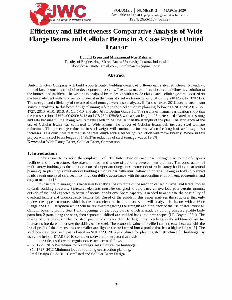
Efficiency and Effectiveness Comparative Analysis of Wide
Flange Beams and Cellular Beams in A Case Project United
Tractor
Donald Essen and Muhammad Nur Rahman
Faculty of Engineering, Mercu Buana University Jakarta, Indonesia
[email protected], [email protected]
Abstract
United Tractors Company will build a sports center building consist of 3 floors using steel structures. Nowadays,
limited land is one of the building development problems. The construction of multi-stored buildings is a solution to
the limited land problem. The writer has analyzed beam design with a Wide Flange and Cellular system. Focused on
the beam element with construction material in the form of steel with steel quality BJ-37, Fy 240 MPa, Fu 370 MPa.
The strength and efficiency of the use of steel tonnage were also analyzed. E-Tabs software 2016 used to steel beam
structure analysis. In this beam design planning refers to the steel structure planning following SNI 1729: 2015, SNI
1727: 2013, AISC 2010, ASCE 7-10, and also AISC Design Guide 31. The results of manual verification show that
the cross-section of WF 400x200x8x13 and CB 250x125x5x8 with a span length of 6 meters is declared to be strong
and safe because fill the strong requirements needs to be smaller than the strength of the plan. The efficiency of the
use of Cellular Beam was compared to Wide Flange, the longer of Cellular Beam will increase steel tonnage
reductions. The percentage reduction in steel weight will continue to increase when the length of steel usage also
increases. This concludes that the use of steel length with steel weight reduction will move linearly. Where in this
project with a steel beam length of 1439.27m reduction of steel tonnage was at 19.5%.
Keywords: Wide Flange Beam, Cellular Beam, Comparison
1. Introduction Enthusiasme to exercise the employees of PT. United Tractor encourage management to provide sports
facilities and infrastructure. Nowadays, limited land is one of building development problem. The construction of
multi-storey buildings is the solution. One of important things in construction of multi-storey building is structural
planning. In planning a multi-storey building structure basically must following criteria: Strong in holding planned
loads, requirements of serviceability, high durability, accordance with the surrounding environment, economical and
easy to maintain [5].
In structural planning, it is necessary to analyze the structure of the reaction caused by axial and lateral forces
towards building structure. Structural elements must be designed to able carry an overload of a certain amount,
outside of the load expected to occur of normal conditions. Spare capacity is needed to anticipate the possibility of
overload factors and undercapacity factors [5]. Based of the problem, this paper analyzes the structures that only
review the upper structure, which is the beam element. In this discussion, will analyze the beams with a Wide
Flange and Cellular system which will be reviewed regarding the strength and efficiency of the use of steel tonnage.
Cellular beam is profile steel I with openings on the body part is which is made by cutting standard profile body
parts into 2 parts along the span, then separated, shifted and welded back into new shapes (J.P. Boyer, 1964). The
results of this process make the steel profile has higher than the beginning, resulting in the addition of inertia.
Increasing inertia will increase the ability of the steel. The economic value of profile I can increase, because with the
initial profile I the dimensions are smaller and lighter can be formed into a profile that has a higher height [6]. The
steel beam structure analysis is based on SNI 1729: 2015 procedures for planning steel structures for buildings. By
using the help of ETABS 2016 computer software for structural analysis.
The rules used are the regulations issued are as follows:
- SNI 1729: 2015 Procedures for planning steel structures for buildings.
- SNI 1727: 2013 Minimum load for building construction planning.
- Steel Design Guide 31 - Castellated and Cellular Beam Design.
31
VOLUME 2 │ NUMBER 2 │ MARCH 2020
Available online at http://proceedings.worldconference.id.
ISSN: 2656-1174 (online)
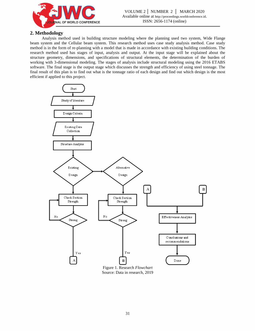
2. Methodology Analysis method used in building structure modeling where the planning used two system, Wide Flange
beam system and the Cellular beam system. This research method uses case study analysis method. Case study
method is in the form of re-planning with a model that is made in accordance with existing building conditions. The
research method used has stages of input, analysis and output. At the input stage will be explained about the
structure geometry, dimensions, and specifications of structural elements, the determination of the burden of
working with 3-dimensional modeling. The stages of analysis include structural modeling using the 2016 ETABS
software. The final stage is the output stage which discusses the strength and efficiency of using steel tonnage. The
final result of this plan is to find out what is the tonnage ratio of each design and find out which design is the most
efficient if applied to this project.
Figure 1. Research Flowchart
Source: Data in research, 2019
32
VOLUME 2 │ NUMBER 2 │ MARCH 2020
Available online at http://proceedings.worldconference.id.
ISSN: 2656-1174 (online)
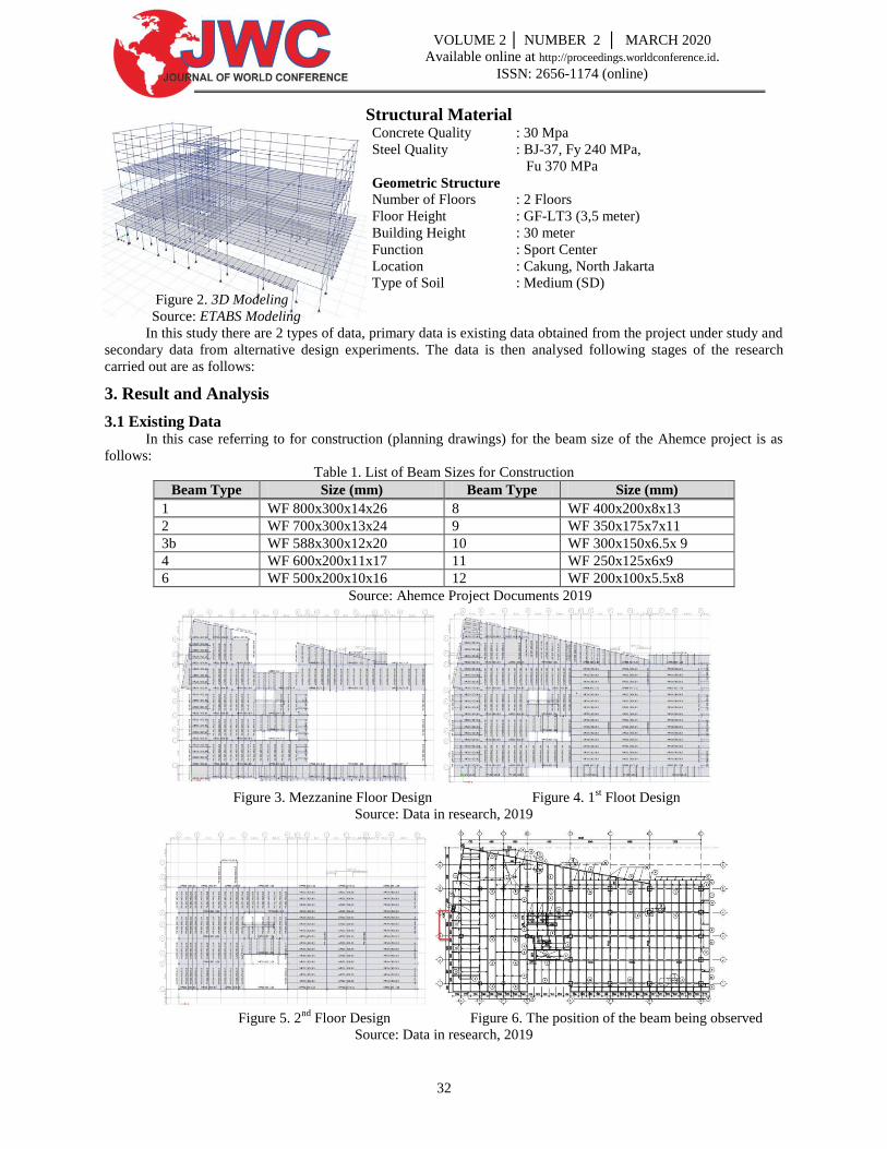
Structural Material Concrete Quality : 30 Mpa
Steel Quality : BJ-37, Fy 240 MPa,
Fu 370 MPa
Geometric Structure
Number of Floors : 2 Floors
Floor Height : GF-LT3 (3,5 meter)
Building Height : 30 meter
Function : Sport Center
Location : Cakung, North Jakarta
Type of Soil : Medium (SD)
Figure 2. 3D Modeling
Source: ETABS Modeling
In this study there are 2 types of data, primary data is existing data obtained from the project under study and
secondary data from alternative design experiments. The data is then analysed following stages of the research
carried out are as follows:
3. Result and Analysis
3.1 Existing Data In this case referring to for construction (planning drawings) for the beam size of the Ahemce project is as
follows:
Table 1. List of Beam Sizes for Construction
Beam Type Size (mm) Beam Type Size (mm)
1 WF 800x300x14x26 8 WF 400x200x8x13
2 WF 700x300x13x24 9 WF 350x175x7x11
3b WF 588x300x12x20 10 WF 300x150x6.5x 9
4 WF 600x200x11x17 11 WF 250x125x6x9
6 WF 500x200x10x16 12 WF 200x100x5.5x8
Source: Ahemce Project Documents 2019
Figure 3. Mezzanine Floor Design Figure 4. 1
st Floot Design
Source: Data in research, 2019
Figure 5. 2
nd Floor Design Figure 6. The position of the beam being observed
Source: Data in research, 2019
33
VOLUME 2 │ NUMBER 2 │ MARCH 2020
Available online at http://proceedings.worldconference.id.
ISSN: 2656-1174 (online)
3.2 Check Section Strength Wide Flange Beam Cellular Beam
Material Data :
WF 400 x 200 x 8 x 13
Yield stress (fy) = 240 MPa
Height (H) = 400 mm
Width (B) = 200 mm
Thick (Flens/tf) = 13 mm
Thick (Web/tw) = 8 mm
Radius of gyration (rx) = 168 mm
Radius of gyration (ry) = 45,4 mm
Momen of inersia (Ix) = 23700 cm^4
Momen of inersia (Iy) = 1740 cm^4
Section area (A) = 8412 mm^2
Modulus of section (Zx) = 1190 cm^3
Modulus of section (Zy) = 174 cm^3
Span length (L) = 6 m
Spacing (b0) = 2 m
Concrete Strength (fc’) = 30 Mpa
Thick concrete = 170 mm
Weight of decks = 240 kg/m2
tc = 70 mm
wr = 200 mm
hr = 50 mm
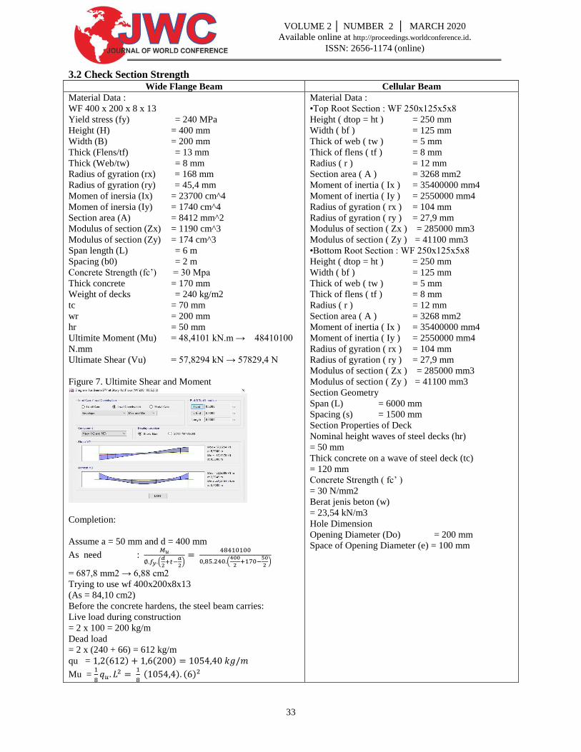
Ultimite Moment (Mu) = 48,4101 kN.m → 48410100
N.mm
Ultimate Shear (Vu) = 57,8294 kN → 57829,4 N
Figure 7. Ultimite Shear and Moment
Completion:
Assume a = 50 mm and d = 400 mm
As need :
(
)
(
)
= 687,8 mm2 → 6,88 cm2
Trying to use wf 400x200x8x13
(As = 84,10 cm2)
Before the concrete hardens, the steel beam carries:
Live load during construction
= 2 x 100 = 200 kg/m
Dead load
= 2 x (240 + 66) = 612 kg/m
qu = ( ) ( )
Mu =
( ) ( )
Material Data :
•Top Root Section : WF 250x125x5x8
Height ( dtop = ht ) = 250 mm
Width ( bf ) = 125 mm
Thick of web ( tw ) = 5 mm
Thick of flens ( tf ) = 8 mm
Radius ( r ) = 12 mm
Section area ( A ) = 3268 mm2
Moment of inertia ( Ix ) = 35400000 mm4
Moment of inertia ( Iy ) = 2550000 mm4
Radius of gyration ( rx ) = 104 mm
Radius of gyration ( ry ) = 27,9 mm
Modulus of section ( Zx ) = 285000 mm3
Modulus of section ( Zy ) = 41100 mm3
•Bottom Root Section : WF 250x125x5x8
Height ( dtop = ht ) = 250 mm
Width ( bf ) = 125 mm
Thick of web ( tw ) = 5 mm
Thick of flens ( tf ) = 8 mm
Radius ( r ) = 12 mm
Section area ( A ) = 3268 mm2
Moment of inertia ( Ix ) = 35400000 mm4
Moment of inertia ( Iy ) = 2550000 mm4
Radius of gyration ( rx ) = 104 mm
Radius of gyration ( ry ) = 27,9 mm
Modulus of section ( Zx ) = 285000 mm3
Modulus of section ( Zy ) = 41100 mm3
Section Geometry
Span (L) = 6000 mm
Spacing (s) = 1500 mm
Section Properties of Deck
Nominal height waves of steel decks (hr)
= 50 mm
Thick concrete on a wave of steel deck (tc)
= 120 mm
Concrete Strength ( fc’ )
= 30 N/mm2
Berat jenis beton (w)
= 23,54 kN/m3
Hole Dimension
Opening Diameter (Do) = 200 mm
Space of Opening Diameter (e) = 100 mm
34
VOLUME 2 │ NUMBER 2 │ MARCH 2020
Available online at http://proceedings.worldconference.id.
ISSN: 2656-1174 (online)
Wide Flange Beam Cellular Beam
Because wf 400x200x8x13 is a compact section, then:
Mn =
Ø Mn = ( ) > Mu OK
Calculate Flexibility Strength of Composite Beam
After the concrete hardens, load factor borne by the
composite beam is :
Mu = 48410100 N.mm ( data from ETABS )
The width of the effective slab of concrete is taken from the
smallest value :
bE =
( )
bE = b0 = 2 m
So the width effectively was taken by 1.5 m
Suppose a neutral plastic axis fell on a concrete plate, then
the height of strength beam hit on the concrete block was :
A =
= 52,78 mm < tc = 70 mm
Because a < tc, means a neutral-plastic axis fell on the
concrete plate, and is on the assumption before.
Nominal Flexibility Strength of Composite Beam :
Mn = (
)
ØMn = ( ) > Mu OK
Next the beams must be checked against the shear :
Vu =
ØVn =
( )( )( )( ) > Vu
OK
Compactness section check :
=
( )
<
√ OK
Calculate Need of Shear Stud
Shear connection total number to cause a full composite
action
For the full composite action :
C =
Use the stud 3/4" - 10cm (Asc = 285mm2) One per section.
Reduction factor strength of stud, rs (Nr = 1, Hs = 10 cm)
rs =
√ (
) *
+
=
(
) *
+
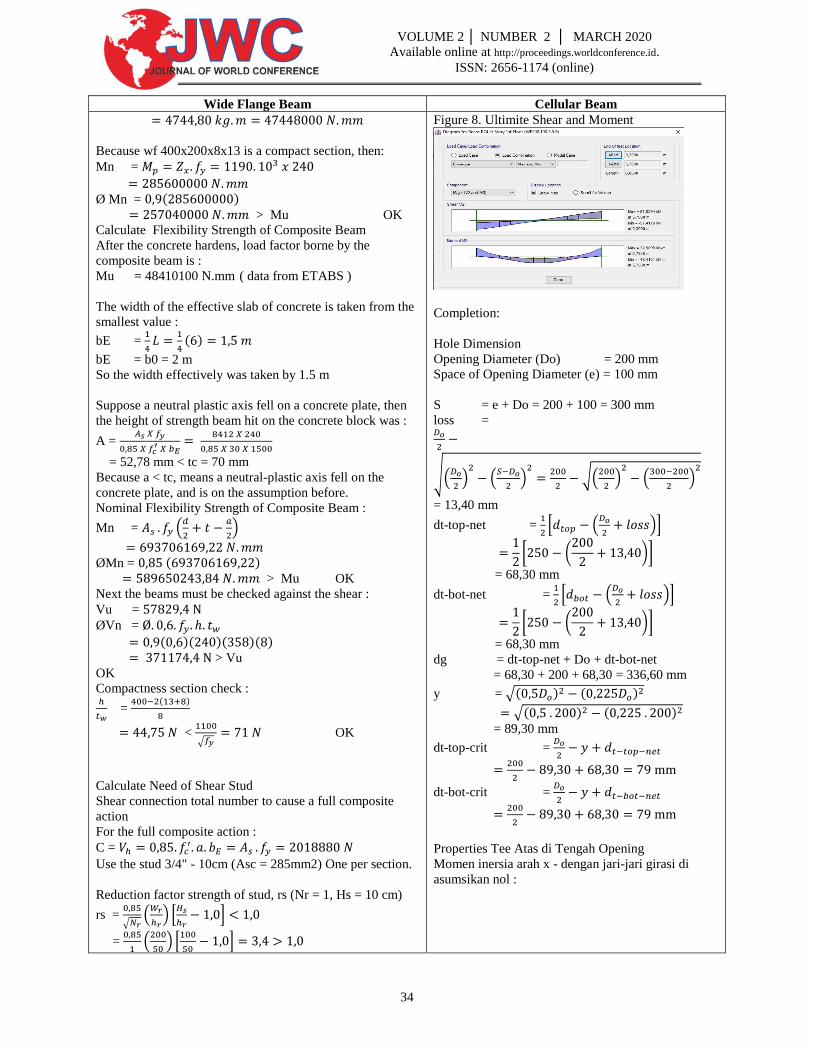
Figure 8. Ultimite Shear and Moment
Completion:
Hole Dimension
Opening Diameter (Do) = 200 mm
Space of Opening Diameter (e) = 100 mm
S = e + Do = 200 + 100 = 300 mm
loss =
√(
)
(
)
√(
)
(
)
= 13,40 mm
dt-top-net =
* (
)+
[ (
)]
= 68,30 mm
dt-bot-net =
* (
)+
[ (
)]
= 68,30 mm
dg = dt-top-net + Do + dt-bot-net
= 68,30 + 200 + 68,30 = 336,60 mm
y = √( ) ( )
√( ) ( )
= 89,30 mm
dt-top-crit =
dt-bot-crit =
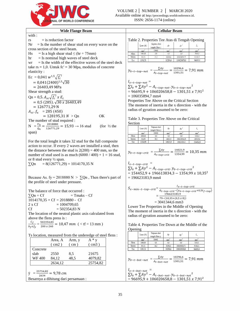
Properties Tee Atas di Tengah Opening
Momen inersia arah x - dengan jari-jari girasi di
asumsikan nol :
35
VOLUME 2 │ NUMBER 2 │ MARCH 2020
Available online at http://proceedings.worldconference.id.
ISSN: 2656-1174 (online)
Wide Flange Beam Cellular Beam
with :
rs = is reduction factor
Nr = Is the number of shear stud on every wave on the
cross section of the steel beam.
Hs = Is a high shear stud ≤ (hr + 75mm)
hr = Is nominal high waves of steel deck
wr = Is the width of the effective waves of the steel deck
take rs = 1,0. Untuk fc' = 30 Mpa, modulus of concrete
elasticity :
Ec = √
( ) √
Shear strength a stud:
Qn = √
( ) √
= ( ) > Qn OK
The number of stud required :
N =
→ 16 stud (for ½ the
span)
For the total lenght it takes 32 stud for the full composite
action to occur. If every 2 waves are installed a stud, then
the distance between the stud is 2(200) = 400 mm, so the
number of stud used is as much (6000 / 400) + 1 = 16 stud,
or 8 stud every ½ span.
∑Qn = 8(126771,29) = 1014170,35 N
Because As. fy = 2018880 N > ∑Qn , Then there's part of
the profile of steel under pressure.
The balance of force that occurred :
∑Qn + Cf = Tmaks – Cf
1014170,35 + Cf = 2018880 - Cf
2 x Cf = 1004709,65
Cf = 502354,83 N
The location of the neutral plastic axis calculated from
above the flens press is :
=
( < tf = 13 mm )
Ts location, measured from the underedge of steel flens :
Area, A
( cm2 )
Arm, y
( cm )
A * y
( cm3 )
Concrete
slab
2550
8,5
21675
WF 400 84,12 48,5 4079,82
2634,12 25754,82
ȳ =
Besarnya a dihitung dari persamaan :
Table 2. Properties Tee Atas di Tengah Opening
=
=
=
= 106035894,7 mm4
Properties Tee Above on the Critical Section
The moment of inertia in the x direction - with the
radius of gyration assumed to be zero:
Table 3. Properties Tee Above on the Critical
Section
=
=
=
= 196623183,9 mm4
=
( )
=
( ( ))
= 3041344,6 mm3
Lower Tee Properties in the Middle of Opening
The moment of inertia in the x direction - with the
radius of gyration assumed to be zero:
Table 4. Properties Tee Down at the Middle of the
Opening
=
=
=
mm4
5333,3
149119,6
154452,9Tee 1354,99 14021,9 196613834,3
Steem 354,99 39,5 14021,9 196613834,29
I o
mm2 (mm) mm
3mm
4
Luas (A)Tinjauan dari
tengah flens yAy Ay
2
Flens 1000,00 0,0 0,0 0,0
mm4
5333,3
91362,5
96695,9Tee 1301,51 10296,6 106020658,8
Steem 301,51 34,2 10296,6 106020658,75
Flens 1000,00 0,0 0,0 0,0
I o
mm2 (mm) mm
3mm
4
Luas (A)Tinjauan dari
tengah flens yAy Ay
2
36
VOLUME 2 │ NUMBER 2 │ MARCH 2020
Available online at http://proceedings.worldconference.id.
ISSN: 2656-1174 (online)
Wide Flange Beam Cellular Beam
a =
Tentukan momen internal terhadap garis kerja Ts :
∑Qn : Mn1 = (
)
= (
)
= 465472715,87 N.mm
Cf : Mn2 = ( (
) )
= ( )
Mn = Mn1 + Mn2 = 658874173,01 N.mm
Øb.Mn = 0,85(658874173,01)
= 560043047,06 N.mm
= 56,00 ton.m > Mu (7,44 ton.m)
Jadi, dapat dipasang 16 buah stud 3/4" - 10 cm dengan jarak
400 mm ( tiap 2 gelombang dek baja ).
Kontrol Lendutan
Sebelum beton mengeras
= 2(240 + 66) = 612 kg/m = 6,12 N/mm
∆1 =
Lendutan akibat beban hidup selama konstruksi
= 2(100) = 200 kg/m = 2 N/mm
∆2 =
Setelah beton mengeras aksi komposit mulai bekerja,
momen inersia penampang komposit Itr dihitung sebagai
berikut :
n =
→ 8
=
Luas A ( cm2 )
Pelat Beton = 225
WF 400 = 84,12
∑ = 309,12
Lengan y ( cm )
Pelat Beton = 8,5
WF 400 = 48,5
A * y ( cm3 )
Pelat Beton = 1912,5
WF 400 = 4079,82
∑ = 5992,32
Io
Pelat Beton = 2700
WF 400 = 23700
d
Pelat Beton = 10,89
WF 400 = -29,11
Io + A * d^2
= 106035894,7 mm4
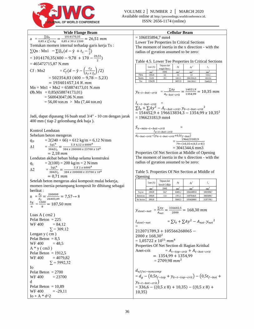
Lower Tee Properties In Critical Sections
The moment of inertia in the x direction - with the
radius of gyration assumed to be zero:
Table 4.5. Lower Tee Properties In Critical Sections
=
=
=
= 196623183,9 mm4
=
( )
=
( ( ))
= 3041344,6 mm3
Properties Of Net Section at Middle of Opening
The moment of inertia in the x direction - with the
radius of gyration assumed to be zero:
Table 5. Properties Of Net Section at Middle of
Opening
=
=
=
=
Properties Of Net Section di Bagian Kritikal
Anet-crit =
=
= ( ) (
)
= (( ) ) (( ) )
mm4
5333,3
149119,6
154452,9Tee 1354,99 14021,9 196613834,3
Steem 354,99 39,5 14021,9 196613834,29
Flens 1000,00 0,0 0,0 0,0
I o
mm2 (mm) mm
3mm
4
Luas (A)Tinjauan dari
tengah flens yAy Ay
2
mm4
106035894,7
106035894,7
212071789,3Net Section 2000,00 336602,5 105566268065
Bottom tee 1000,00 11,9 11911,3 141879546,81
Top tee 1000,00 324,7 324691,2 105424388518
I o
mm2 (mm) mm
3mm
4
Luas (A)Tinjauan dari
bawah CellularAy Ay
2
37
VOLUME 2 │ NUMBER 2 │ MARCH 2020
Available online at http://proceedings.worldconference.id.
ISSN: 2656-1174 (online)
Wide Flange Beam Cellular Beam
Pelat Beton = 546513,23
WF 400 = 23548336,7
∑ = 24094849,93
ȳ =
Karena struktur dianggap sebagai balok komposit parsial,
maka momen inersia harus direduksi sebagai berikut :
Iefektif = ( )√
= ( )√
= 17084407,59 cm4
Lendutan akibat beban hidup :
q = 2(488,4) = 976,8 kg/m = 9,77 N/mm
∆3 =
Lendutan jangka panjang akibat beban mati berupa partisi
dihitung sebagai berikut :
=
Luas A ( cm2 )
Pelat Beton = 112,5
WF 400 = 84,12
∑ = 197
Lengan y ( cm )
Pelat Beton = 8,5
WF 400 = 48,5
A * y ( cm3 )
Pelat Beton = 956,25
WF 400 = 4079,82
∑ = 5036,07
Io
Pelat Beton = 1350
WF 400 = 23700
d
Pelat Beton = 17,11
WF 400 = -22,89
Io + A * d^2
Pelat Beton = 675413,15
WF 400 = 14551208,76
∑ = 15226621,91
ȳ =
Iefektif’ = ( )√
= ( )√
= 10798947,79 cm4
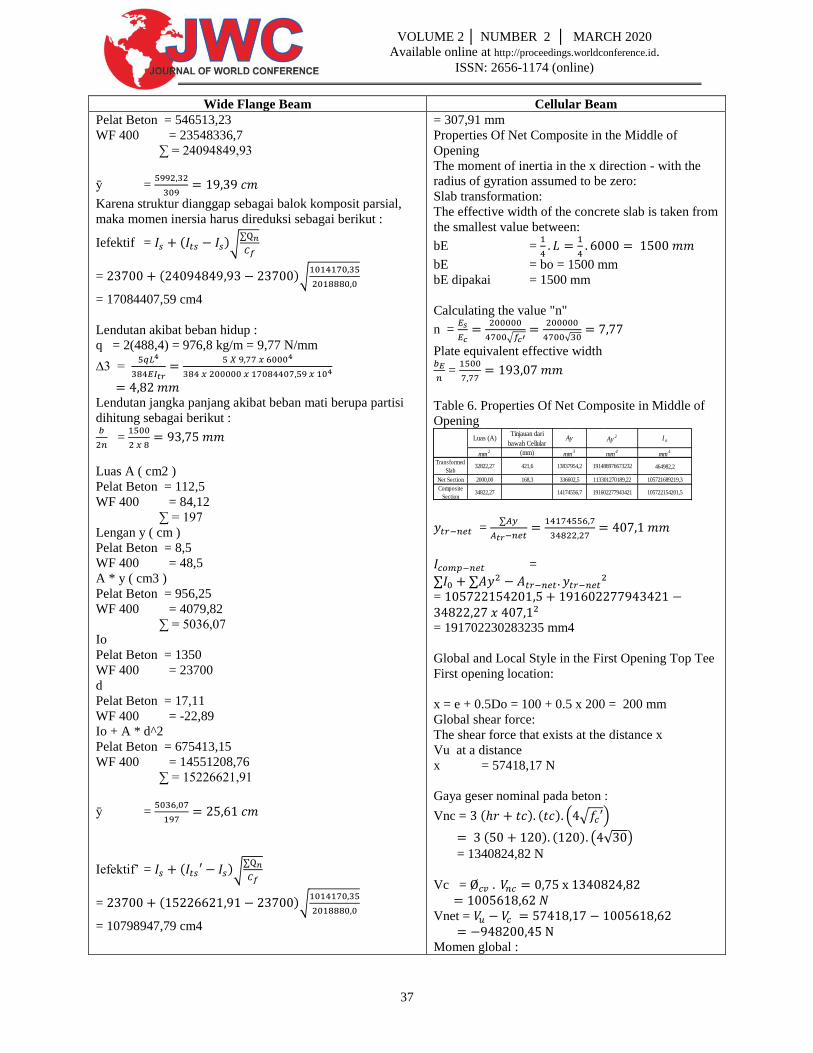
= 307,91 mm
Properties Of Net Composite in the Middle of
Opening
The moment of inertia in the x direction - with the
radius of gyration assumed to be zero:
Slab transformation:
The effective width of the concrete slab is taken from
the smallest value between:
bE =
bE = bo = 1500 mm
bE dipakai = 1500 mm
Calculating the value "n"
n =
√
√
Plate equivalent effective width
=
Table 6. Properties Of Net Composite in Middle of
Opening
=
=
= = 191702230283235 mm4
Global and Local Style in the First Opening Top Tee
First opening location:
x = e + 0.5Do = 100 + 0.5 x 200 = 200 mm
Global shear force:
The shear force that exists at the distance x
Vu at a distance
x = 57418,17 N
Gaya geser nominal pada beton :
Vnc = ( ) ( ) ( √ )
( ) ( ) ( √ )
= 1340824,82 N
Vc =
Vnet = Momen global :
mm4
464982,2
105721689219,3
105722154201,5Composite
Section34822,27 14174556,7 191602277943421
Net Section 2000,00 168,3 336602,5 113301270189,22
Transformed
Slab32822,27 421,6 13837954,2 191488976673232
I o
mm2 (mm) mm
3mm
4
Luas (A)Tinjauan dari
bawah CellularAy Ay
2
38
VOLUME 2 │ NUMBER 2 │ MARCH 2020
Available online at http://proceedings.worldconference.id.
ISSN: 2656-1174 (online)
Wide Flange Beam Cellular Beam
∆5 =
Lendutan total yang terjadi :
∆1 + ∆3 + ∆5 = 2,18 + 4,82 + 0,01
= 7,01 mm ≤
OK
Dari hasil verifikasi perhitungan manual di atas
menunjukkan bahwa penampang WF 400x200x8x13 dengan
panjang bentang 6 meter dinyatakan kuat dan aman karena
memenuhi syarat kuat perlu ( Mu ), lebih kecil dari kuat
rencana ( ØMn ).
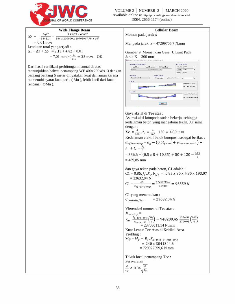
Momen pada jarak x
Mu pada jarak x = 47299705,7 N.mm
Gambar 9. Momen dan Geser Ultimit Pada
Jarak X = 200 mm
Gaya aksial di Tee atas :
Asumsi aksi komposit sudah bekerja, sehingga
kedalaman beton yang mengalami tekan, Xc sama
dengan :
Xc =
Kedalaman efektif balok komposit sebagai berikut :
= ( )
= ( )
= 489,85 mm
dan gaya tekan pada beton, C1 adalah :
C1 =
= 23632,04 N
C1 =
C1 yang menentukan :
=
Vierendeel momen di Tee atas :
=
(
)
(
)
= 23705011,14 N.mm
Kuat Lentur Tee Atas di Kritikal Area
Yielding :
Mp =
= 729922699,6 N.mm
Tekuk local penampang Tee :
Persyaratan
√
39
VOLUME 2 │ NUMBER 2 │ MARCH 2020
Available online at http://proceedings.worldconference.id.
ISSN: 2656-1174 (online)
Wide Flange Beam Cellular Beam
Maka
Momen nominal
Mn =
= 729922699,6 N.mm
Kapasitas Ratio untuk Tee Atas Area Kritikal di
Opening Pertama
=
< 1 OK
Gaya Global dan Lokal di Tee Bawah Opening ke
Enam
Lokasi opening ke enam
x = ( ) ( ) = 2000 mm
Gaya geser global :
Gaya geser yang ada pada jarak x
Vu pada jarak x = 22247,2 N
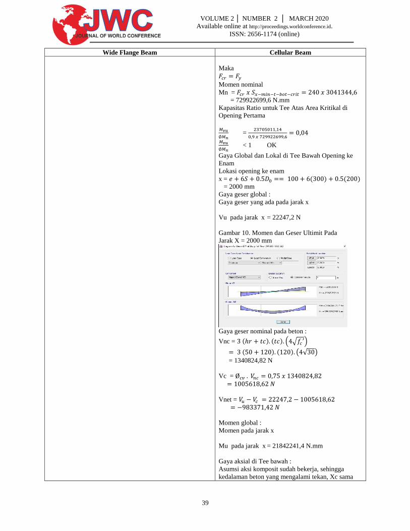
Gambar 10. Momen dan Geser Ultimit Pada
Jarak X = 2000 mm
Gaya geser nominal pada beton :
Vnc = ( ) ( ) ( √ )
( ) ( ) ( √ )
= 1340824,82 N
Vc =
Vnet =
Momen global :
Momen pada jarak x
Mu pada jarak x = 21842241,4 N.mm
Gaya aksial di Tee bawah :
Asumsi aksi komposit sudah bekerja, sehingga
kedalaman beton yang mengalami tekan, Xc sama
40
VOLUME 2 │ NUMBER 2 │ MARCH 2020
Available online at http://proceedings.worldconference.id.
ISSN: 2656-1174 (online)
Wide Flange Beam Cellular Beam
dengan :
Xc =
Kedalaman efektif balok komposit sebagai berikut :
= ( )
= ( )
= 477,25 mm
dan gaya tekan pada beton, C1 adalah :
C1 =
= 147700,23 N
C1 =
C1 yang menentukan :
=
Vierendeel momen di Tee bawah :
=
(
)
(
)
= 24584285,39 N.mm
Kekuatan tarik Tee bawah di area kritikal
Pn =
Kuat Lentur Tee Bawah di Kritikal Area
Yielding :
Mp =
= 729922699,6 N.mm
Tekuk local penampang Tee :
Persyaratan
√
Maka
Momen nominal
Mn =
= 729922699,6 N.mm
Persamaan Interaksi Untuk Tee Bawah Kritikal Area
di Opening 6
Persamaan 1 :
=
Persamaan 2 :
41
VOLUME 2 │ NUMBER 2 │ MARCH 2020
Available online at http://proceedings.worldconference.id.
ISSN: 2656-1174 (online)
Wide Flange Beam Cellular Beam
=
Menentukan (Kontrol)
Nilai max = 0,12 < 1 OK
Momen Lentur di Web Post Pertama
Gaya tekan Tee bawah di opening pertama
Lihat perhitungan diatas, untuk gaya aksial yang
terjadi di Tee bawah opening, Tul, adalah sebagai
berikut :
Tul =
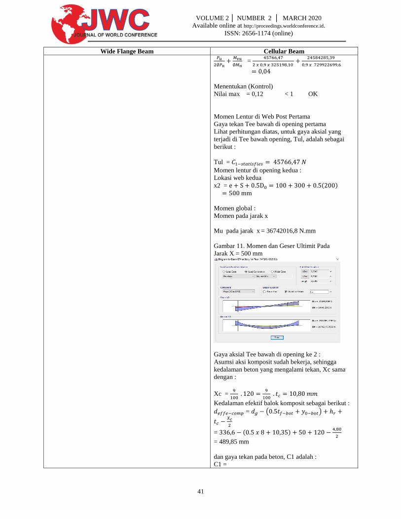
Momen lentur di opening kedua :
Lokasi web kedua
x2 = ( )
Momen global :
Momen pada jarak x
Mu pada jarak x = 36742016,8 N.mm
Gambar 11. Momen dan Geser Ultimit Pada
Jarak X = 500 mm
Gaya aksial Tee bawah di opening ke 2 :
Asumsi aksi komposit sudah bekerja, sehingga
kedalaman beton yang mengalami tekan, Xc sama
dengan :
Xc =
Kedalaman efektif balok komposit sebagai berikut :
= ( )
= ( )
= 489,85 mm
dan gaya tekan pada beton, C1 adalah :
C1 =
42
VOLUME 2 │ NUMBER 2 │ MARCH 2020
Available online at http://proceedings.worldconference.id.
ISSN: 2656-1174 (online)
Wide Flange Beam Cellular Beam
= 53172,08 N
C1 =
C1 yang menentukan :
=
Gaya Geser Horisontal di Web Post :
Vuh =
Momen Lentur di Web Post :
Muh =
Kuat Geser Horizontal Web Post
Gaya tekan Tee bawah di opening pertama
=
Kuat Lentur Web Post
Momen lentur elastis :
Me = ( )
( ( ))
= 9056768 N.mm
Momen tekuk :
C1 = (
) (
)
= (
) (
)
= 8,17
C2 = (
) (
)
= (
) (
)
= 2,85
C3 = (
) (
)
= (
) (
)
= 5,33
= [ (
) (
)
]
= [ (
) (
)
]
= 4206370,61 N.mm
Geser Vertikal Tee di Opening Pertama
43
VOLUME 2 │ NUMBER 2 │ MARCH 2020
Available online at http://proceedings.worldconference.id.
ISSN: 2656-1174 (online)
Wide Flange Beam Cellular Beam
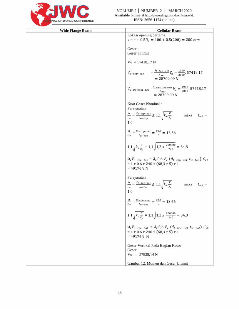
Lokasi opening pertama
x = ( )
Geser :
Geser Ultimit
Vu = 57418,17 N
=
=
Kuat Geser Nominal :
Persyaratan
√
maka
=
√
= √
= ( )
= ( )
= N
Persyaratan
√
maka
=
√
= √
= ( )
= ( )
= N
Geser Vertikal Pada Bagian Kotor
Geser
Vu = 57829,14 N
Gambar 12. Momen dan Geser Ultimit
44
VOLUME 2 │ NUMBER 2 │ MARCH 2020
Available online at http://proceedings.worldconference.id.
ISSN: 2656-1174 (online)
Wide Flange Beam Cellular Beam
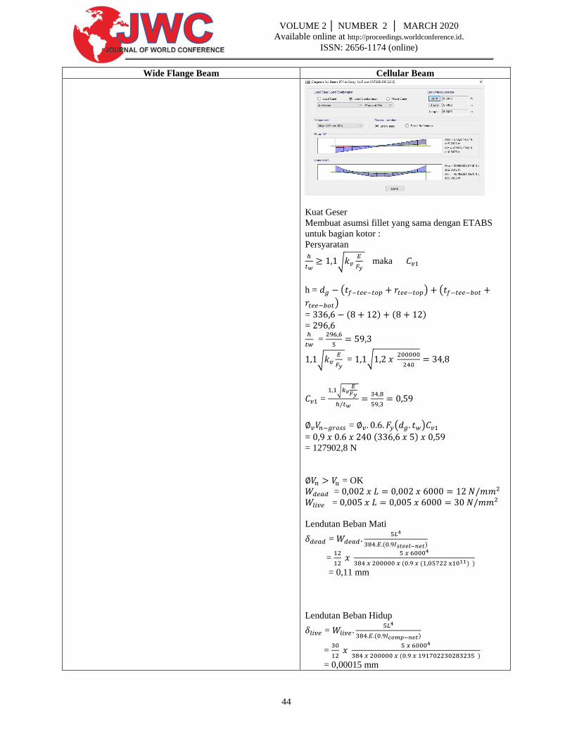
Kuat Geser
Membuat asumsi fillet yang sama dengan ETABS
untuk bagian kotor :
Persyaratan
√
maka
h = ( ) (
)
= ( ) ( ) =
=
√
= √
= √
= ( )
= ( )
= 127902,8 N
= OK
=
=
Lendutan Beban Mati
=
( )
=
( ( ) )
= 0,11 mm
Lendutan Beban Hidup
=
( )
=
( )
= 0,00015 mm
45
VOLUME 2 │ NUMBER 2 │ MARCH 2020
Available online at http://proceedings.worldconference.id.
ISSN: 2656-1174 (online)
Wide Flange Beam Cellular Beam
Lendutan total yang terjadi :
+ = 0,11 + 0,00015
= 0,11015 mm ≤
OK
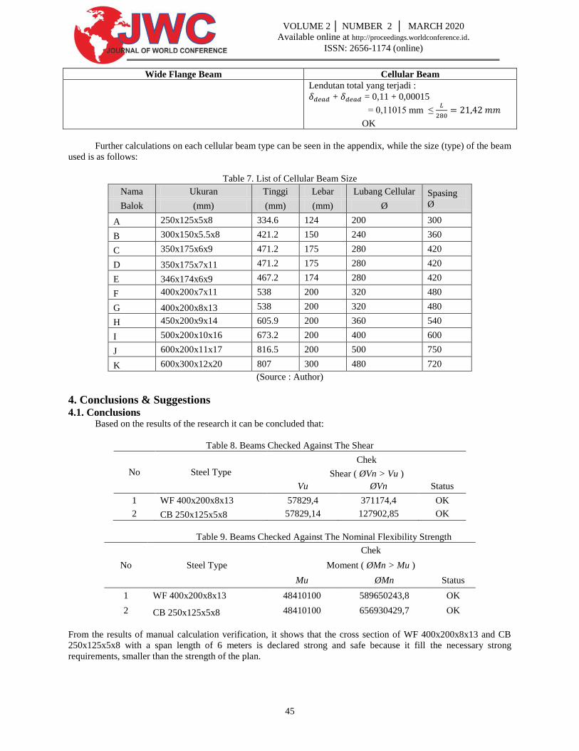
Further calculations on each cellular beam type can be seen in the appendix, while the size (type) of the beam
used is as follows:
Table 7. List of Cellular Beam Size
Nama Ukuran Tinggi Lebar Lubang Cellular Spasing
Ø Balok (mm) (mm) (mm) Ø
A 250x125x5x8 334.6 124 200 300
B 300x150x5.5x8 421.2 150 240 360
C 350x175x6x9 471.2 175 280 420
D 350x175x7x11 471.2 175 280 420
E 346x174x6x9 467.2 174 280 420
F 400x200x7x11 538 200 320 480
G 400x200x8x13 538 200 320 480
H 450x200x9x14 605.9 200 360 540
I 500x200x10x16 673.2 200 400 600
J 600x200x11x17 816.5 200 500 750
K 600x300x12x20 807 300 480 720
(Source : Author)
4. Conclusions & Suggestions 4.1. Conclusions
Based on the results of the research it can be concluded that:
Table 8. Beams Checked Against The Shear
No Steel Type
Chek
Shear ( ØVn > Vu )
Vu ØVn Status
1 WF 400x200x8x13 57829,4 371174,4 OK
2 CB 250x125x5x8 57829,14 127902,85 OK
Table 9. Beams Checked Against The Nominal Flexibility Strength
No Steel Type
Chek
Moment ( ØMn > Mu )
Mu ØMn Status
1 WF 400x200x8x13 48410100 589650243,8 OK
2 CB 250x125x5x8 48410100 656930429,7 OK
From the results of manual calculation verification, it shows that the cross section of WF 400x200x8x13 and CB
250x125x5x8 with a span length of 6 meters is declared strong and safe because it fill the necessary strong
requirements, smaller than the strength of the plan.
46
VOLUME 2 │ NUMBER 2 │ MARCH 2020
Available online at http://proceedings.worldconference.id.
ISSN: 2656-1174 (online)
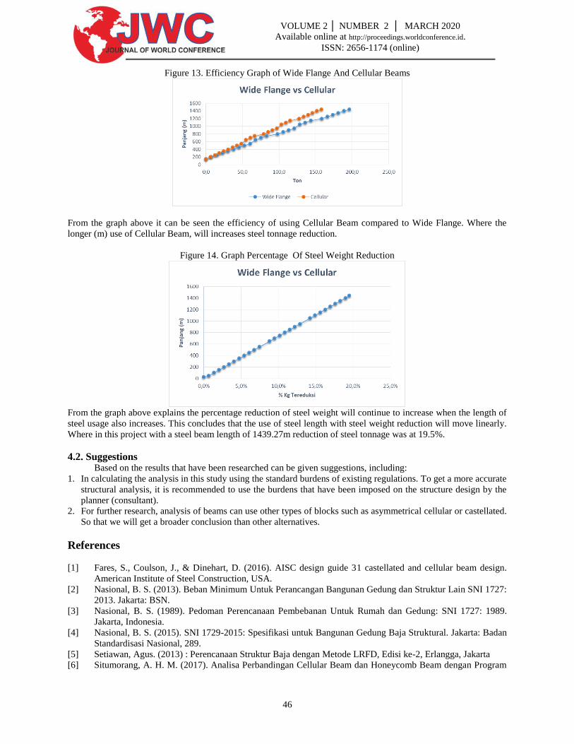
Figure 13. Efficiency Graph of Wide Flange And Cellular Beams
From the graph above it can be seen the efficiency of using Cellular Beam compared to Wide Flange. Where the
longer (m) use of Cellular Beam, will increases steel tonnage reduction.
Figure 14. Graph Percentage Of Steel Weight Reduction
From the graph above explains the percentage reduction of steel weight will continue to increase when the length of
steel usage also increases. This concludes that the use of steel length with steel weight reduction will move linearly.
Where in this project with a steel beam length of 1439.27m reduction of steel tonnage was at 19.5%.
4.2. Suggestions Based on the results that have been researched can be given suggestions, including:
1. In calculating the analysis in this study using the standard burdens of existing regulations. To get a more accurate
structural analysis, it is recommended to use the burdens that have been imposed on the structure design by the
planner (consultant).
2. For further research, analysis of beams can use other types of blocks such as asymmetrical cellular or castellated.
So that we will get a broader conclusion than other alternatives.
References
[1] Fares, S., Coulson, J., & Dinehart, D. (2016). AISC design guide 31 castellated and cellular beam design.
American Institute of Steel Construction, USA.
[2] Nasional, B. S. (2013). Beban Minimum Untuk Perancangan Bangunan Gedung dan Struktur Lain SNI 1727:
2013. Jakarta: BSN.
[3] Nasional, B. S. (1989). Pedoman Perencanaan Pembebanan Untuk Rumah dan Gedung: SNI 1727: 1989.
Jakarta, Indonesia.
[4] Nasional, B. S. (2015). SNI 1729-2015: Spesifikasi untuk Bangunan Gedung Baja Struktural. Jakarta: Badan
Standardisasi Nasional, 289.
[5] Setiawan, Agus. (2013) : Perencanaan Struktur Baja dengan Metode LRFD, Edisi ke-2, Erlangga, Jakarta
[6] Situmorang, A. H. M. (2017). Analisa Perbandingan Cellular Beam dan Honeycomb Beam dengan Program
47
VOLUME 2 │ NUMBER 2 │ MARCH 2020
Available online at http://proceedings.worldconference.id.
ISSN: 2656-1174 (online)
Ansys. Jurnal Teknik Sipil USU, 7(1).
Biographies
Donald Essen was a professor who, today, actively teaches at the Mercubuana University Jakarta with a concentrate
on structure. He got a bachelor's degree in civil engineering from the bandung institute of technology in 2002, an
Master’ degree in engineering specialist from the bandung institute of technology in 2007. He is a member of the
Indonesian society of civil and engineers, registered as haki professional engineer, also Class A professional for
construction engineering from Dinas Pengawasan dan Penertiban Bangunan DKI Jakarta (DPPB). Currently the
director of ESK Enjiniring Company.
Muhammad Nur Rahman was born in Yogyakarta, a special region of yogyakarta on August 9th, 1997. After
graduation a vocational high school education in building engineering department continued his undergraduate civil
engineering education at mercubuana university jakarta in 2016 to 2020 by compiling the final project is “Efficiency
and effectiveness comparative analysis of wide flange beams and cellular beams in a case project united tractor”,
also active as a staff in building constuction project.