Embed Size (px)
Citation preview
EFFECTS OF TRANSVERSE SHEAR DEFORMATION ON MAXIMUM DEFLECTION
OF COMPOSITE BEAMS WITH VARIOUS LAMINATE CONFIGURATIONS AND
BOUNDARY CONDITIONS
by
WEI-TSEN LU
Presented to the Faculty of the Graduate School of
The University of Texas at Arlington in Partial Fulfillment
of the Requirements
for the Degree of
MASTER OF SCIENCE IN AEROSPACE ENGINEERING
THE UNIVERSITY OF TEXAS AT ARLINGTON
AUGUST 2015

ii
Copyright © by Wei-Tsen Lu 2015
All Rights Reserved

iii
Acknowledgements
I must express my appreciation and gratitude to my supervising professor, Dr. Wen
Chan, for his guidance, support, and encouragement throughout my research in every
aspect especially in composite fields. This thesis could not have been completed without
his efforts. He also treats all students as his children. I will always consider him as my
“Academic Father”.
In addition, I would like to express my sincere thanks to Dr. Ashfaq Adnan and Dr.
Seiichi Nomura, committee members, for their valuable advice and assistance.
I would like to thank the entire faculty of Mechanical and Aerospace Engineering for
their help in building by understanding of the subject.
I would like to thank my friend, Alistair and Ming Feng, for their assistance and
encouragement at this thesis.
Finally, I would to thank my parents for their patience and encouragement. Without
their support, I cannot fulfill my dream. I would like to express my special
acknowledgment to my girlfriend, Ching Wen Hwang. She very supports me during the
time of study. Without her support and understanding, this thesis would not have been
completed.
August 7, 2015
iv
Abstract
EFFECTS OF TRANSVERSE SHEAR DEFORMATION ON MAXIMUM DEFLECTION
OF COMPOSITE BEAMS WITH VARIOUS LAMINATE CONFIGURATIONS
AND BOUNDARY CONDITIONS
Wei-Tsen Lu, M.S.
The University of Texas at Arlington, 2015
Supervising Professor: Wen S. Chan
Analytical methods are developed for determining deflection of composite beams
under transverse load with various boundary conditions and laminate configurations. The
present methods include development of expression for 1-D equivalent bending stiffness
with and without presence of twisting curvature and prediction of the beam deflection
accounting for transverse shear effect. Finite element analysis of 3-D ANSYS models is
conducted by using Solid186 elements. The present analytical model is executed by
using MATLAB program. Both analytical and FEM models were first validated by using
isotropic material in the model and comparing the existing solutions.
The composite beams with rectangular cross-section and small ratios of its
length to its width and its width to its depth were selected for study. These conditions
were chosen for enhancing the effect of the shear deformation. Various boundary
conditions used for study include simply support, fixed at both ends, and cantilever
beams under uniformly distributed or concentrated load, respectively. The maximum
deflection of composite beams is investigated for transverse shear effects due to
laminates with symmetric vs unsymmetrical layups and balanced vs unbalanced layups.
v
Among all of the case studies, the analytical results agree well with the results obtained
from FEM.
It is found that for a given laminated beam under the same type of loading, effect
of transverse shear on beam deflection is identical regardless with simply supported and
fixed both ends but more pronounced for the case of cantilever beam. However, the
effect of shear deformation on beam deflection due to stacking sequence is insignificant
regardless of the type of loading.
vi
Table of Contents
Acknowledgements .............................................................................................................iii
Abstract .............................................................................................................................. iv
List of Illustrations ............................................................................................................. viii
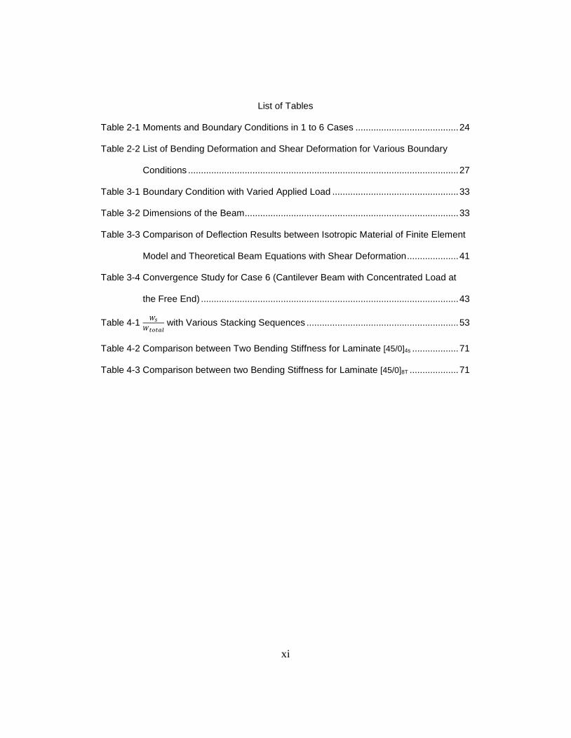
List of Tables ...................................................................................................................... xi
Chapter 1 Introduction......................................................................................................... 1
1.1 Overview of Composite Materials ........................................................................ 1
1.2 Issues Considered ............................................................................................... 3
1.3 Literature Review................................................................................................. 5
1.4 Objective in This Thesis ...................................................................................... 7
1.5 Outline of the Thesis .......................................................................................... 7
Chapter 2 Analysis of Composite Beams with Various Boundary Conditions .................... 9
2.1 Lamina Constitutive Equation............................................................................... 9
2.2 Laminate Constitutive Equation.......................................................................... 11
2.3 Inverse of Load-Deformation Relations: Laminate Compliances ....................... 14
2.4 Effects of Transverse Shear ............................................................................... 15
2.5 Equivalent Bending Stiffness of Composite Beam ............................................. 18
2.6 Equivalent Shear Modulus ........................................................................... 20
2.7 Beam Deflection ................................................................................................. 22
2.8 Cases Study ....................................................................................................... 23
Chapter 3 Finite Element Analysis .................................................................................... 28
3.1 Overview ............................................................................................................. 28
3.2 Element Type ..................................................................................................... 29
3.2.1 Two – Dimensional Elements .......................................................................... 29
3.2.2 Three - Dimensional Elements ........................................................................ 30
vii
3.2.3 Element Type in this Study.............................................................................. 31
3.3 Meshing .............................................................................................................. 31
3.4 Boundary and Loading Conditions ..................................................................... 33
3.5 Composite Beam Modeling in ANSYS ............................................................... 34
3.6 Verification of Finite Element model ................................................................... 40
3.7 Convergence of FE Solutions............................................................................. 41
Chapter 4 Result and Discussion ...................................................................................... 44
4.1 Effects of Boundary Conditions .......................................................................... 44
4.2 Effects of Stacking Sequences .......................................................................... 53
4.3. Effects of Fiber Orientations .............................................................................. 56
4.4.Comparison of Error % between Two Bending Stiffness ................................... 64
Chapter 5 Conclusion ........................................................................................................ 73
Appendix A Derived Moments for Different Bounday Conditions Presented in
Chapter 2 ....................................................................................................... 75
Appendix B Derived Beam Equations from Case 2 to Case 6 ........................................ 80
Appendix C Data ............................................................................................................... 94
Appendix D ANSYS Code for Case 1 ............................................................................. 119
Appendix E MATLAB Code ............................................................................................. 133
References ...................................................................................................................... 160
Biographical Information ................................................................................................. 162
viii
List of Illustrations
Figure 2-1 Coordinate System of Lamina ........................................................................... 9
Figure 2-2 Deformation in x-z plane .................................................................................. 16
Figure 2-3 Simply Beam Under Uniform Distribution Load ............................................... 23
Figure 3-1 Typical Mesh of the 3-D Model ........................................................................ 32
Figure 3-2 Uniform Distributed Load on Top Surface of the Laminate ............................. 35
Figure 3-3 Concentrated Load on Middle Line of Top Surface of the Laminate ............... 35
Figure 3-4 Transverse Load on the Cross-section ar the Free End ................................. 36
Figure 3-5 SOLID186 Element .......................................................................................... 37
Figure 3-6 on the Middle Line of Right Cross-section of Simply Supported Beam37
Figure 3-7 , and on the Middle Line of Left Cross-section of Simply
Supported Beam ............................................................................................. 38
Figure 3-8 All Degrees of Freedom Constrained on the Nodes of the Fixed Right End
Cross-section .................................................................................................. 38
Figure 3-9 All Degrees of Freedom Constrained on the Nodes of the Fixed Left End
Cross-section .................................................................................................. 39
Figure 3-10 All Degrees of Freedom Constrained on the Nodes of the Fixed End of the
Cantilever Beam ............................................................................................ 39
Figure 4-1 Comparison between Analytical and ANSYS Results for [15/0]4s .................. 45
Figure 4-2 Comparison between Analytical and ANSYS Results for [15/0]8T ................. 45
Figure 4-3 Comparison between Analytical and ANSYS Results for [0/15]4s .................. 46
Figure 4-4 Comparison between Analytical and ANSYS Results for [30/0]4s .................. 46
Figure 4-5 Comparison between Analytical and ANSYS Results for [30/0]8T ................. 47
Figure 4-6 Comparison between Analytical and ANSYS Results for [0/30]4s .................. 47
Figure 4-7 Comparison between Analytical and ANSYS Results for [45/0]4s .................. 48
ix
Figure 4-8 Comparison between Analytical and ANSYS Results for [45/0]8T ................. 48
Figure 4-9 Comparison between Analytical and ANSYS Results for [0/45]4s .................. 49
Figure 4-10 Comparison between Analytical and ANSYS Results for [60/0]4s................ 49
Figure 4-11 Comparison between Analytical and ANSYS Results for [60/0]8T ............... 50
Figure 4-12 Comparison between Analytical and ANSYS Results for [0/60]4s................ 50
Figure 4-13 Comparison between Analytical and ANSYS Results for [75/0]4s................ 51
Figure 4-14 Comparison between Analytical and ANSYS Results for [75/0]8T ............... 51
Figure 4-15 Comparison between Analytical and ANSYS Results for [0/75]4s................ 52
Figure 4-16 Variation of
in Different Laminates with respect to the Fiber
Orientations ................................................................................................... 54
Figure 4-17 Comparison of Ws Deflection due to Shear between , , and
for θ= 45 ........................................................................................ 55
Figure 4-18 Comparison of Wb Deflection due to Bending between , , and
for θ= 45 .......................................................................................... 55
Figure 4-19 Variation of 𝜂𝑥𝑦,𝑥 with respect to Fiber Orientations ..................................... 57
Figure 4-20 Variation of
in Different Laminates with respect to the Fiber Orientation
for Case 1 ...................................................................................................... 57
Figure 4-21 Variation of
in Different Laminates with respect to the Fiber Orientation
for Case 2 ...................................................................................................... 58
Figure 4-22 Variation of
in Different Laminates with respect to the Fiber Orientation
for Case 3 ...................................................................................................... 58
Figure 4-23 Variation of
in Different Laminates with respect to the Fiber Orientation
for Case 4 ...................................................................................................... 59
x
Figure 4-24 Variation of
in Different Laminates with respect to the Fiber Orientation
for Case 5 ...................................................................................................... 59
Figure 4-25 Variation of
in Different Laminates with respect to the Fiber Orientation
for Case 6 ...................................................................................................... 60
Figure 4-26 Variation of
for Laminates [θ/ 0 ]4s in Different Cases ....................... 61
Figure 4-27 Variation of
for Laminates [θ/ 0 ]8T in Different Cases ....................... 62
Figure 4-28 Variation of
for Laminates [0 /θ]4s in Different Cases ........................ 63
Figure 4-29 Error % in Case 1 by Using Bending Stiffness in Case B ............................. 65
Figure 4-30 Error % in Case 1 by Using Bending Stiffness in Case A ............................. 65
Figure 4-31 Error % in Case 2 by Using Bending Stiffness in Case B ............................. 66
Figure 4-32 Error % in Case 2 by Using Bending Stiffness in Case A ............................. 66
Figure 4-33 Error % in Case 3 by Using Bending Stiffness in Case B ............................. 67
Figure 4-34 Error % in Case 3 by Using Bending Stiffness in Case A ............................. 67
Figure 4-35 Error % in Case 4 by Using Bending Stiffness in Case B ............................. 68
Figure 4-36 Error % in Case 4 by Using Bending Stiffness in Case A ............................. 68
Figure 4-37 Error % in Case 5 by Using Bending Stiffness in Case B ............................. 69
Figure 4-38 Error % in Case 5 by Using Bending Stiffness in Case A ............................. 69
Figure 4-39 Error % in Case 6 by Using Bending Stiffness in Case B ............................. 70
Figure 4-40 Error % in Case 6 by Using Bending Stiffness in Case A ............................. 70
xi
List of Tables
Table 2-1 Moments and Boundary Conditions in 1 to 6 Cases ........................................ 24
Table 2-2 List of Bending Deformation and Shear Deformation for Various Boundary
Conditions ......................................................................................................... 27
Table 3-1 Boundary Condition with Varied Applied Load ................................................. 33
Table 3-2 Dimensions of the Beam ................................................................................... 33
Table 3-3 Comparison of Deflection Results between Isotropic Material of Finite Element
Model and Theoretical Beam Equations with Shear Deformation .................... 41
Table 3-4 Convergence Study for Case 6 (Cantilever Beam with Concentrated Load at
the Free End) .................................................................................................... 43
Table 4-1
with Various Stacking Sequences ........................................................... 53
Table 4-2 Comparison between Two Bending Stiffness for Laminate [45/0]4s .................. 71
Table 4-3 Comparison between two Bending Stiffness for Laminate [45/0]8T ................... 71
1
Chapter 1
Introduction
1.1 Overview of Composite Materials
In a broad sense the word “composite” means “made of two or more different parts”.
A composite material contains two or more materials which are combined in a
macroscopic scale to get the useful third material whose mechanical performance and
properties are superior to those of the constituent material acting independently. There
are two phases of the composite. One phase is continuous phase which is called matrix.
The other phase is discontinuous phase which is called reinforcement, or reinforcing
material. The properties of composite material result from properties of the constituent
materials, their geometrical distribution, and their interaction. Thus, to describe a
composite material, it will be necessary to specify the nature of the constituents and their
properties, the geometry of the reinforcement and its distribution, and the reinforcement
interface.
The phase of the composite system plays different roles, which depend on the type of
the application of the composite material. The reinforcement, usually in the form of fibers,
may provide some stiffening but only limited strengthening of the material in the case of
low to medium performance composite materials. On the other hand, the matrix is the
main load-bearing constituent governing in the mechanical properties of the material. In
the case of high performance composite materials, continuous fiber reinforcement is the
backbone of the material. The matrix phase provides protection for the sensitive fibers,
bonding, support, and local stress transfer from one fiber to another. The interface can
play an important role in controlling the failure mechanisms, failure propagation, fracture
toughness, and the overall stress-strain behavior to failure of the material.
2
Advanced composites are becoming more widely used as alternative to metallic
structures. Applications of composites have been used to the aircraft, marine, automotive,
sporting goods, biomedical industries, civil construction, and aerospace structures
because of following reasons.
High specific stiffness
High specific strength
Low density
Design flexibility
Corrosion resistance
Low thermal expansion
Parts count reduction
Easy fabrication
Aerospace structures, for example, have to operate in a very high degree of
dimensional stability under environment conditions. Some composites can be applied in
the aerospace structures because they can be designed to have nearly zero coefficient of
thermal expansion.
The high specific stiffness, high specific strength, and low density characteristics
makes composites highly desirable in primary and secondary structures of both military
and civilian aircrafts. The strongest sign of acceptance of composites in civil aviation is
using in Boeing 787, and the world largest airliner, Airbus A380. Composite materials
account for approximately 50% of the weight of the Boeing 787, including most of the
fuselage and wings.
3
One of the important advantages of composites is reducing in acquisition and life
circle due to weight savings, lower tooling costs, reduced number of parts and joints, and
reduced maintenance. These advantages are diluted when considering the high cost of
raw materials, fiber, and auxiliary materials used in fabrication and assembly of
composite structures.
Composite structure design can be validated by three different methods on their
performance – closed form analytical solutions, finite element Method, and testing. In fact
composite structures are normally certified by test not by the analysis although testing in
nature is very tedious and expansive. In these cases, finite element method takes
advantages because it can deal with large and complex structures with high accuracy.
However, in design stage, parametric study is often performed to determine the optimal
design of laminate configuration. Hence, it is not an efficient analysis tool. As a result, a
simplified structure should be used to perform an initial analysis by using the theoretical
or analytical solutions. Also, once the parameters are programmed into mathematical
software, it is easily modified the changes and effects of each variables. It should be
check for the validation between finite element method and theoretical solutions. Once
the result can be validated, more complexities in modeling can be added. This will insure
saving cost and time efficiently.
1.2 Issues Considered
Special considerations should be made on structural sectional property, finite
element meshing, boundary conditions, and stacking sequences while designing and
modeling of composite structure. As composite materials are inherently 2-dimensional
orthotropic behavior, four material properties are needed for describing the structural
response. These include Young’s modulus in fiber and transverse directions, in plane
shear modulus and in-plane Poisson’s ratio. The 2-dimensional sectional property of
4
composite structures can be evaluated by using lamination theory. However, designing
for 1-dimentional beam structure, the 1 dimensional sectional properties are required in
order to have better evaluation of beam structural response.
Finite element meshing of pattern and size is also an important issue needed to be
considered. The accuracy of the model depends on mesh pattern and size which
includes the element numbers and its aspect ratio. The insufficient numbers of element
will lead to inaccurate results. Moreover, if aspect ratio is too large, the error of the
deflection will increase. Consequently, using proper meshing in modeling can decrease
the error of the result.
Moreover, boundary condition used in structure modeling is one of the important
issues that need special considerations. Unlike isotropic materials, composite material
exhibits coupling behavior of in-plane coupling, out-of-plan coupling and between in-
plane and out-of-plane coupling. The in-plane coupling is a structure under an axial load
inducing shear deformation or vice versa. A structure under bending inducing twisting
curvature is the out-plane-load coupling or vice versa. The coupling between in-plane and
out-of-plane is a structure under in-plane load induces the out-of-plane deformation
(curvature) or vice versa. Hence, if a structural boundary is constrained in certain
direction, it may suppress the corresponding response. As a result, additional
force/moment will be induced. In this case, the actual loading condition will not be the
same condition that is intended to have. Hence,, boundary condition plays an important
role when accurately modeling composite materials.
5
Lastly, the stacking sequence of composite materials has to be considered. If the
laminate has symmetric and balanced stacking sequence, the behavior will react no
coupling effect. However, unbalanced or un-symmetric laminates will have extension-
shear coupling and extension-bending coupling while applying a tension load along the
longitudinal axis. As a result, stacking sequence has to be considered carefully because
it will affect the deflection of composite materials.
1.3 Literature Review
Composite beam structures have been extensively studied before. Several
outstanding textbooks on composites include this subject [1, 2 and 3]. Among those
books, the equivalent bending stiffness used in their beam analysis ignores the coupling
effect. In finding the equivalent property, Chen and Chan [4] presented a method for
calculating equivalent properties of the lumped layer. They stated that if un-symmetric
and un-balanced laminas were lumped together, the effect of shear deformation on the
effective moduli was ignored. Later, Lin, et al. [5] proposed a method for equivalent
properties including thermal expansion coefficient of lumped layer.
Hu [6] proposed an analytical method to investigate the deformation of cantilever
beams with various symmetric laminates. The method takes transverse shear effects and
twisting coupling effects into account. Drummond and Chan [7] analytically and
experimentally studied the bending stiffness of composites I-beam. Parambil et. al. [8]
developed a non-conventional method to analyze composite laminated I-beam under
bending. Closed form expressions for centroid and bending stiffness of I-beam were
developed. The ply stress of I-beam under bending was also obtained and the results
were in excellent agreement with finite element results.
Sanghavi and Chan [9] analytically studied the torsion behavior of composite I-
beam. A closed-form expression for torsional and warping stiffness as well as shear
6
center is also developed.
Karama, Afaq, and Mistou [10] proposed the model of bending deformation under
different types of loading and boundary conditions, showing that their approach is much
closer to the finite element analysis than Sine model. Different stresses and
displacements plotted with respect to the thickness and length for bending deformation,
showing that this model is still trying to approach the finite element results. As a result,
they concluded the present exponential model is more precise than other analytical
models for multi-layered structures compared to finite element analysis.
Akavci et al. [11] analytically studied the bending analysis of cross-ply rectangular
thick plates by using first order shear deformation theory. The results of examples
showed that the mid-plane deflection and stresses of the laminate are significantly
influenced by foundation stiffness. When thickness ratio a/h (length divided by thickness)
decreases, the effect of foundation stiffness decreases. However, when length to
thickness ratio L/h = 100, distribution of deflections and shear stresses for both of
foundation stiffness are significantly different.
Schnabl, Saje, Turk, and Planinc [12] proposed a mathematical model for the
analysis of geometrically and materially linear layered beams with different materials and
geometric characteristics of each layer. This model took the transverse shear
deformation of each layer of multi-layer into account. The shear deformation on vertical
deflection increases with decreasing length to thickness ratio. Also, the influence of shear
effects are significant for composite beams with E/G ≥ 16 where the influence is about 15
% for L/h = 10, and about 250 % for short beams with L/h = 3.
Ascione, Feo, and Mancusi [13] presented a one-dimensional kinematical model for
studying fiber reinforced beams. This model is able to take into account the transverse
shear deformation. It is known that composite beams are significantly influence by shear
7
deformation because of their low shear moduli. In their work, they not only considered
shear deformability within the context of a simplified one-dimensional model, but also
overcome the difficulties related to a 3D analysis of these deformation. Consequently, the
results of this model have more precious deflections than Vlaso’s theory. Wu and Sun [14]
developed a simple theory for thin-walled composite beams by allowing the deformation
of beam cross-sectional contour and shearing stain of mid-axis.
1.4 Objective in this Thesis
Structural members are often idealized as beams in practical engineering analysis.
It is known that shear deformation increases with decreasing length to thickness ratio for
isotropic beams. However, for composite beams, large shear deformation will be
produced due to different fiber orientations, stacking sequences, and boundary conditions.
In analyzing a composite structure, classical lamination theory is used to perform
the laminate analysis by using finite element analysis. However, analyzing the composite
structure by finite element method is still time consuming and expensive. As a result, it
should need to develop a simply method that can accurately analyze composite
behaviors.
The main purpose of the thesis is to investigate maximum deflections of
composite beams with various boundary conditions and applied loads. Deflections due to
normal and shear stresses will be discussed and total deflections will be compared to
finite element results.
1.5 Outline of the Thesis
Chapter 2 is a review of composite beams starts from classical lamination theory.
Then briefly introduces the effect of transverse shear deformation and shear stiffness.
Lastly, composite beams with various boundary conditions have represented and
maximum deflection in each case is derived. Chapter 3 describes the finite element

8
analysis including element type, mesh techniques, and convergent study. Chapter 4
presents results obtained by both analytical and finite element methods. A comparison
between these two methods was conducted and discussed. Finally, conclusion and
recommendations for the future work are presented in Chapter 5.
9
Chapter 2
Analysis of Composite Beams with Various Boundary Conditions
This Chapter includes brief description of the stress/strain relationship of lamina
and the constitutive equation of laminated plate. Modification of constitutive equation of
laminated plate into the equation for the laminated beam is also presented and the
rationale of the structural behavior of 2D into 1D is explained. Closed-form expressions of
the maximum deflection are developed for the beams under transversely concentrated
and uniformly distributed loads with different boundary condition.
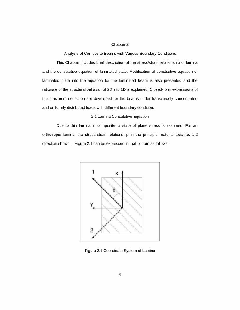
2.1 Lamina Constitutive Equation
Due to thin lamina in composite, a state of plane stress is assumed. For an
orthotropic lamina, the stress-strain relationship in the principle material axis i.e. 1-2
direction shown in Figure 2.1 can be expressed in matrix from as follows:
Figure 2.1 Coordinate System of Lamina
10
[
] [
] [
]
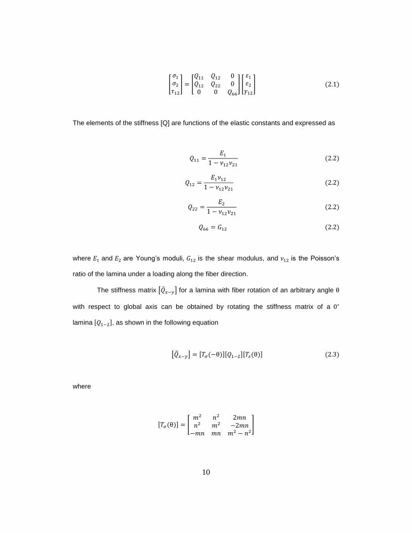
The elements of the stiffness [Q] are functions of the elastic constants and expressed as
where and are Young’s moduli, is the shear modulus, and is the Poisson’s
ratio of the lamina under a loading along the fiber direction.
The stiffness matrix [ ] for a lamina with fiber rotation of an arbitrary angle
with respect to global axis can be obtained by rotating the stiffness matrix of a
lamina , as shown in the following equation
[ ]
where
[
]
11
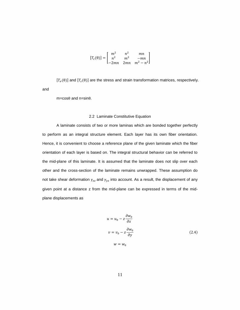
[
]
and are the stress and strain transformation matrices, respectively.
and
m=cos and n=sin
2.2 Laminate Constitutive Equation
A laminate consists of two or more laminas which are bonded together perfectly
to perform as an integral structure element. Each layer has its own fiber orientation.
Hence, it is convenient to choose a reference plane of the given laminate which the fiber
orientation of each layer is based on. The integral structural behavior can be referred to
the mid-plane of this laminate. It is assumed that the laminate does not slip over each
other and the cross-section of the laminate remains unwrapped. These assumption do
not take shear deformation and into account. As a result, the displacement of any
given point at a distance z from the mid-plane can be expressed in terms of the mid-
plane displacements as
𝑥
𝑦
12
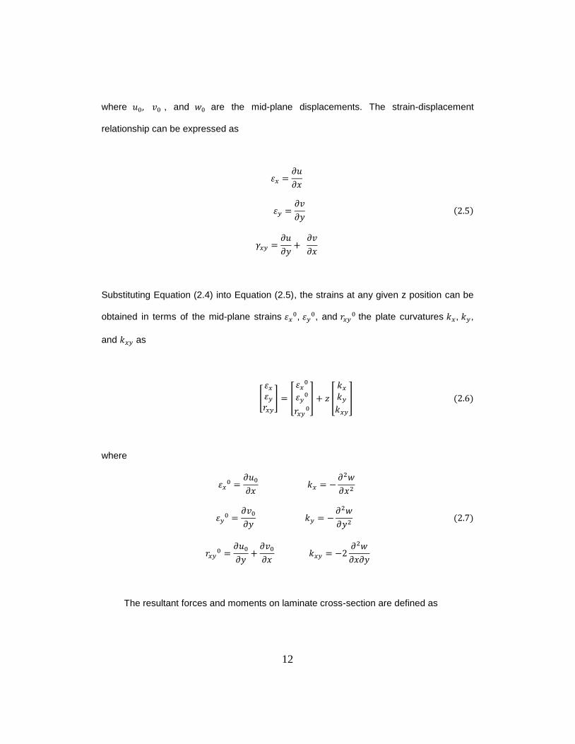
where , and are the mid-plane displacements. The strain-displacement
relationship can be expressed as
𝑥
𝑦
𝑦
𝑥
Substituting Equation (2.4) into Equation (2.5), the strains at any given z position can be
obtained in terms of the mid-plane strains ,
, and the plate curvatures , ,
and as
[
] [
] [
]
where
𝑥
𝑥
𝑦
𝑦
𝑦
𝑥
𝑥 𝑦
The resultant forces and moments on laminate cross-section are defined as
13
∫ ∫
∫ ∫
∫ ∫
Substituting Equation (2.8) into Equation (2.6), the constitutive equation can be obtained
as
[
] [
] [
]
where
∑( )
∑( )
∑( )
where is called the extensional stiffness matrix, is called the coupling stiffness
matrix as it contributes in the coupling effect in response to different kind of load, is
called the bending stiffness matrix, and is the distance from mid-plane to k-th lamina.
14
The presence of matrix induces a coupling between stretching and
bending/twisting of laminate. That is, in-plane strains can be due to not only in-plane
resultants but also the out plane bending moments in the laminates. Similarly, bending
and/or twisting strains do not induce resultant moment only, but also induce in-plane
resultants. For symmetric laminate, the coupling stiffness matrix is a zero matrix which
implies that in-plane deformation and the moment resultants are decoupled. On the other
hand, unsymmetrical laminates will produce bending/twisting of the laminate in additional
to the extensional and shear deformation.
This relationship (Equation 2.9) is usually referred as “Laminated Plate Theory”
or simply as “Classical Lamination Theory”.
2.3 Inverse of Load-Deformation Relations: Laminate Compliances
Since multidirectional laminates are characterized by stress discontinuities from ply
to ply, it is preferable to work with strain because there are continuous through the
thickness. For this reason, it has to invert the load-deformation relations from Equation
(2.9), and to express strains and curvatures as a function of applied loads and moments.
Equation (2.9) can be rewritten as
[
] [
] [
]
where [
] [
]
It should be noted that the stiffness matrices , , and are symmetric and the
combined stiffness matrix is also symmetric. It can be easily proved that the inverse
15
of a symmetric matrix is also a symmetric matrix. Hence, the compliance matrix and
its individual sub matrices and are also symmetric. However, and may not be
symmetric nor equal to each other. In fact, is the transpose of obtained from it by
interchanging columns and rows.
2.4 Effects of Transverse Shear
In the classical lamination theory discussed before, it was assumed that the
laminate is thin compared to its lateral dimensions and that straight lines normal to the
middle surface remain straight and normal to that surface after deformation. Under these
assumptions, the transverse shear strains and stresses are considered as zero. However,
these assumptions are not valid in the case of thick cross-section laminated beams,
sandwich beams, and thin-walled beams. The assumption that planes of the cross-
section remain planes may no longer be valid because cross-sections exhibit deformation.
As a result, an additional angle will be induced. Beam theory based on these relaxed
assumptions is known as shear deformation beam theory, most commonly known as the
Timoshenko beam theory.
Although the Timoshenko beam theory takes the transverse shear effect into
account, the coupling effects due to un-symmetry and balanced laminates on the
structure response should be also included. As a result, through simulating different
composite beams to investigate shear deformations of the beam, the composite beam
equation of predicting the tip displacements can be developed.
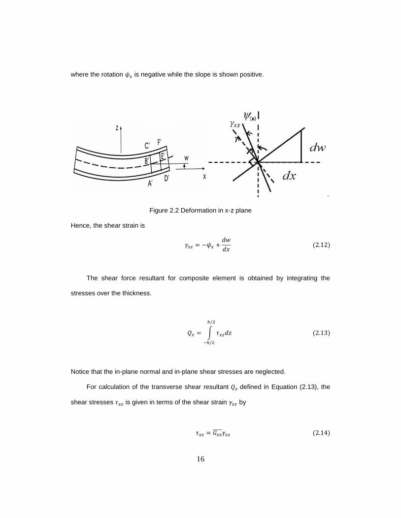
According to Figure 2.2, the cross-sections may not necessarily remain
perpendicular to the deformed middle surface of the core. The slop of the middle surface
𝑥⁄ differs from the magnitude of the rotation of the cross-section .
𝑥
16
where the rotation is negative while the slope is shown positive.
Figure 2.2 Deformation in x-z plane
Hence, the shear strain is
𝑥
The shear force resultant for composite element is obtained by integrating the
stresses over the thickness.
∫
Notice that the in-plane normal and in-plane shear stresses are neglected.
For calculation of the transverse shear resultant defined in Equation (2.13), the
shear stresses is given in terms of the shear strain by
17
where is the equilibrium transverse shear modulus of the composite laminate
introduced in the section 2.6.
Since the shear stress distribution is not a constant across the laminate thickness,
an average shear approach was often used in analysis of beam with isotropic material.
In shear deformation theory, it is customary to use a correction factor k introduced as a
multiplicative parameter in the constitutive relations between transverse shear forces and
transverse shear strains. The need for a correction factor in the first-order theory
originates from the fact that transverse shear strains and shear stresses are uniform
through the thickness instead of the classical parabolic shear stress distribution with zero
shear stresses on the surface of the laminates. The correction factor k is determined from
exact solution for the shear stresses at the center of the laminate in terms of the
transverses shear forces. For the rectangular cross-section of the isotropic material, the
value of the shear correction factor k is determined as 1.2. However, for the composite
field, transverse shear stresses are varied with stacking sequences and fiber orientations
of the laminates. Since there is no closed-form expression for shear stress distribution
available, the shear correction factor is chosen to be 1.2 used in isotropic material for this
study.
With shear correction factor k, integration of the shear stress given by Equation
(2.12) into Equation (2.14) over the laminate thickness h (Equation (2.13)) yields
(
𝑥)
(
𝑦)
18
2.5 Equivalent Bending Stiffness of Composite Beam
The material of composites is inherent a 2-dimensional property. However, analysis
of a beam is based upon a 1-dimensional structural response. The equivalent bending
stiffness of one-dimensional beam is the proportional constant of the bending moment to
the corresponding curvature of the beam. To evaluate the 1-dimensional equivalent
bending stiffness, the structural response is needed to be taken into consideration. The
structural response of the beam structure can be observed as induced the twisting
curvature due to the bending. For isotropic beam, no twisting curvature will be induced as
a beam is subjected to bending. For a composite beam under bending, the induced
twisting curvature can be negligible if the ratio of the beam width to its depth is small.
Hence, two approaches in determining the equivalent bending stiffness of a
composite beam will be discussed.
Case A: Twisting curvature is suppressed
For a beam under a bending moment M across b, the width of the beam, no other
loadings are applied. Since the twisting curvature is suppressed, Mxy is induced. Since
the loads per unit width is employed in the lamination theory, we have
where b is the width of the beam.
Under these assumptions, Equation (2.9) becomes
[
] [
] [
]
19
can be in terms of and presented in Equation (2.19)
Substituting Equation (2.19) into Equation (2.18) obtains
(
) (
)
(
) (
)
For the bending case, only is applied which means = 0. Equation (2.20) and
(2.21) becomes
(
) (
)
Hence, the equivalent bending stiffness can be written as
and is shown below
Case B: Twisting curvature is allowed but Mxy does not exist.
With this assumption, Equation (2.10) becomes
20
[
] [
] [
]
For the bending case, is equal to zero. Because moments describe in Lamination
theory are per unit width, the equivalent bending stiffness of the laminated beam can be
written as
where is the flexural compliance of the composite beam.
To summary, there are two expressions of equivalent bending stiffness for a
composite beam developed in this study. One takes twisting effect into account and the
other does not. The results of beam deflection by using different bending stiffness will be
discussed and presented in Chapter 4.
2.6 Equivalent Transverse Shear Modulus
The constitutive equation of laminates including the effect of transverse shear
deformation is, by Equation (2.15), the superposition of Equation (2.9) from the classical
laminate theory and the equation that involves the transverse shear resultants and
can be expressed as
[
] ∑ ∫ [
]
Equation (2.26) can be rewrite as
21
[
] [
] [
]
with
∑
The stiffness constant, referred to laminates’ reference direction is a
functions of the constants referred to the layer’s principal directions as shown.
with
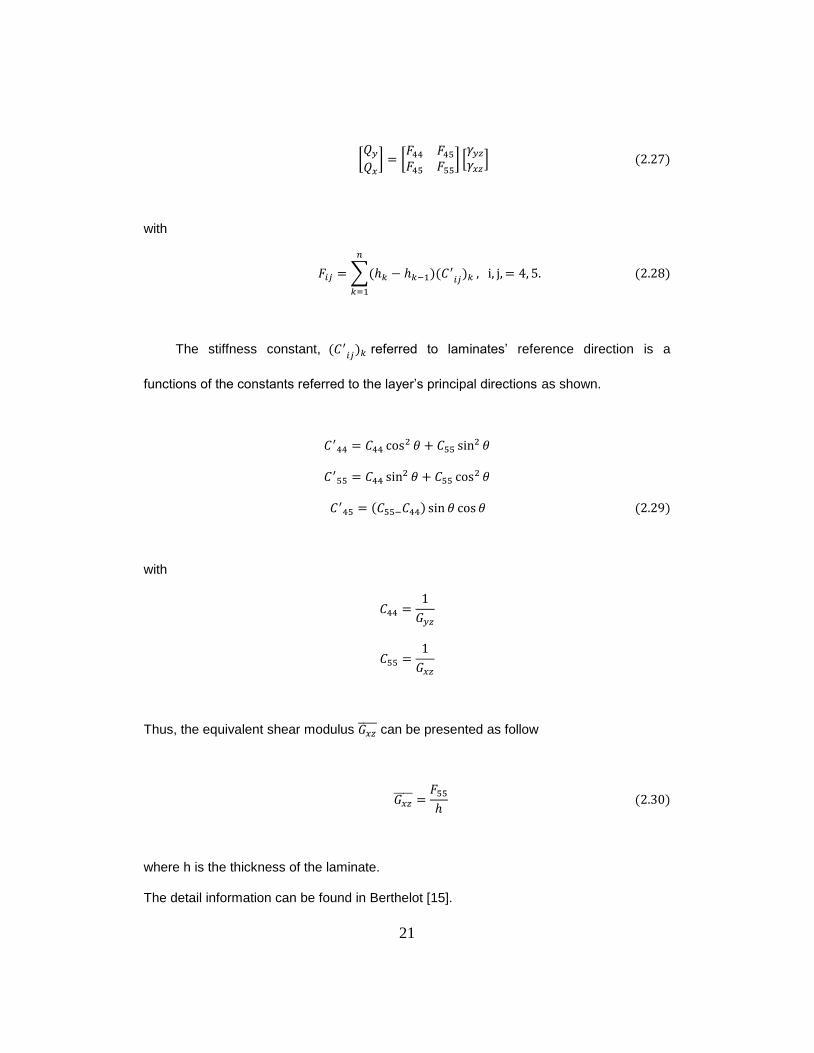
Thus, the equivalent shear modulus can be presented as follow
where h is the thickness of the laminate.
The detail information can be found in Berthelot [15].
22
2.7 Beam Deflection
The bending strain and transverse shear strain along the x-direction are given by
𝑥
The curvature is given in Equation (2.7) as
𝑥
where is the rotation of cross-section which is not perpendicular to the mid-axis.
The shear force resultants are obtained by integrating the shear stresses over
the layer thickness. Therefore, the constitutive equation for transvers shear along the x-
direction is
(
𝑥)
Substituting Equation (2.25) with which is given by Equation (2.33), and the shear
force given by Equation (2.34) substituted into the equilibrium equation yields a different
equation for bending
𝑥
𝑥
where
23
𝑥
This equation is convenient for several beam-bending cases where the variation
of moment along the beam is known from static equilibrium considerations. The detail
derived equation can be found in Carlsson and Kardomateas [16].
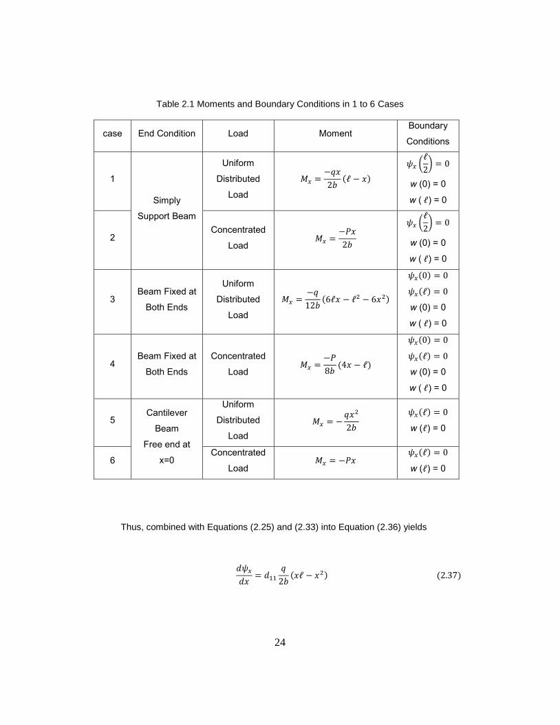
2.8 Cases Study
Laminated composite beams with three different boundary conditions such as
simply support, fixed end at both side, and cantilever beams were investigated the effect
of shear deformation on the beam deflection under uniform distributed and concentrated
loads, respectively. The boundary conditions and moment of different type structural
problems are presented in Table 2.1. The detail derived equations are list in APPENDIX
A.
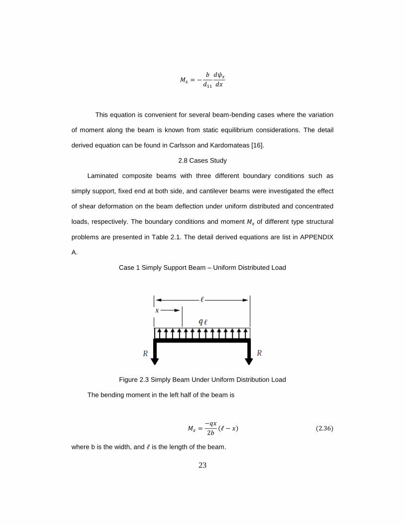
Case 1 Simply Support Beam – Uniform Distributed Load
Figure 2.3 Simply Beam Under Uniform Distribution Load
The bending moment in the left half of the beam is
𝑥
𝑥
where b is the width, and is the length of the beam.
24
Table 2.1 Moments and Boundary Conditions in 1 to 6 Cases
case End Condition Load Moment Boundary
Conditions
1
Simply
Support Beam
Uniform
Distributed
Load
𝑥
𝑥
(
)
w (0) = 0
w ( ) = 0
2 Concentrated
Load
𝑃𝑥
(
)
w (0) = 0
w ( ) = 0
3 Beam Fixed at
Both Ends
Uniform
Distributed
Load
𝑥 𝑥
w (0) = 0
w ( ) = 0
4 Beam Fixed at
Both Ends
Concentrated
Load
𝑃
𝑥
w (0) = 0
w ( ) = 0
5 Cantilever
Beam
Free end at
x=0
Uniform
Distributed
Load
𝑥
w ( ) = 0
6 Concentrated
Load 𝑃𝑥
w ( ) = 0
Thus, combined with Equations (2.25) and (2.33) into Equation (2.36) yields
𝑥
𝑥 𝑥
25
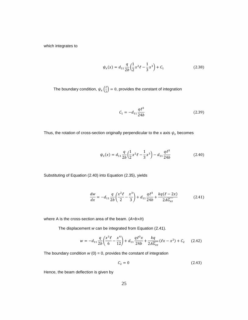
which integrates to
𝑥
(
𝑥
𝑥 )
The boundary condition, (
) , provides the constant of integration
Thus, the rotation of cross-section originally perpendicular to the x axis becomes
𝑥
(
𝑥
𝑥 )
Substituting of Equation (2.40) into Equation (2.35), yields
𝑥
(𝑥
𝑥
)
𝑥
where A is the cross-section area of the beam. (A=b h)
The displacement w can be integrated from Equation (2.41).
(𝑥
𝑥
)
𝑥
𝑥 𝑥
The boundary condition w (0) = 0, provides the constant of integration
Hence, the beam deflection is given by
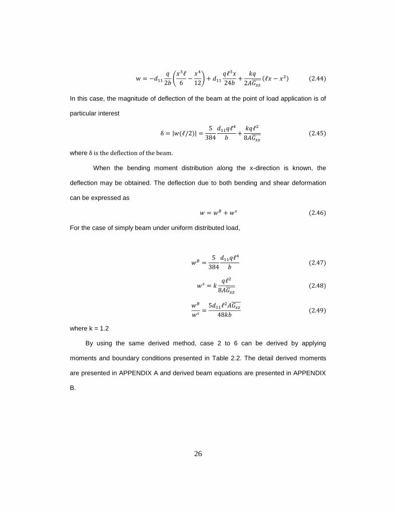
26
(𝑥
𝑥
)
𝑥
𝑥 𝑥
In this case, the magnitude of deflection of the beam at the point of load application is of
particular interest
| |
where
When the bending moment distribution along the x-direction is known, the
deflection may be obtained. The deflection due to both bending and shear deformation
can be expressed as
For the case of simply beam under uniform distributed load,
where k = 1.2
By using the same derived method, case 2 to 6 can be derived by applying
moments and boundary conditions presented in Table 2.2. The detail derived moments
are presented in APPENDIX A and derived beam equations are presented in APPENDIX
B.
27
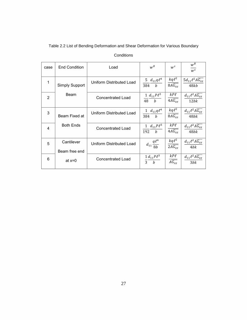
Table 2.2 List of Bending Deformation and Shear Deformation for Various Boundary
Conditions
case End Condition Load
1 Simply Support
Beam
Uniform Distributed Load
2 Concentrated Load
𝑃
𝑃
3 Beam Fixed at
Both Ends
Uniform Distributed Load
4 Concentrated Load
𝑃
𝑃
5 Cantilever
Beam free end
at x=0
Uniform Distributed Load
6 Concentrated Load
𝑃
𝑃
28
Chapter 3
Finite Element Analysis
3.1 Overview
Due to the various reasons such as geometry, boundary conditions, and
environmental conditions, the real-problems are too complicated to be solved analytically.
Once the material changes from the isotropic material to the orthotropic material, the
complexity of the problem increases. If all these problems are considered as the
analytical process, the solutions are practically unreachable. As a result, computer aided
engineering (CAE) have been developed by translating analytical methods into
convenient computer software to simulate problems effectively. These computer aided
engineering can help to insure that the model features will be operate as designed in real
conditions and to validate the theoretical results.
To divide the whole structural body into many small and geometrically simple bodies,
which are called elements, is a basic concept of finite element methods. These elements
have finite sizes so the method is named “Finite Element Methods (FEM)”. Large
numbers of commercial programs exist with many finite element analysis capabilities for
different engineering disciplines. They help to solve problems from a simple linear
analysis to a nonlinear transient analysis. Some CAE have special capabilities to analyze
composite material because these methods accept user programmed element
formulations and custom constitutive equations such as and . These
types of systems are commonly categorized into three parts: the pre-processor, the
processor, and the post processor. In this study, is used to investigate
behaviors of composite materials under various boundary conditions and configurations.
The main propose of the study in this Chapter is to obtain the results by finite element
29
method that are used for comparison with results from analytical method developed in
Chapter 2.
3.2 Element Types
Many different element types are contained in the element library of .
The element type determines the used element formulation such as degree of freedom,
the interpolation functions, and the dimensions. Two – dimensional elements and three –
dimensional elements must to be used for the composite structures due to its orthotropic
behaviors. Through using the help files, proper element types for
laminated composite structures are considered and listed below as a reference.
3.2.1 Two – Dimensional Elements
2-D elements are widely implemented and differentiated by elements types,
which are called shell elements. The element types should be chosen based on the
problems and desired results. Classical Lamination Theory of composite is based on
Kirchhoff theory that inter-lamina shear strain is assumed to be zero. However, the shear
effect in the composite structure is significant. As a result, the Mindlin theory, which takes
the transverse shear deformation into account, is used in . Hence, the Shell
elements listed below have included the transverse shear deformation in their stiffness
matrix.
SHELL181 (Finite strain layered shell):
Suitable for analyzing thin to moderately thick shell structures
Four-node element with six degrees of freedom at each node
Well-suited for linear, large rotation and has large strain capabilities
Highly accurate, even with coarse meshes
Includes the effects of transverse shear deformation
30
SHELL281 (Finite strain layered shell):
Suitable for analyzing thin to moderately thick shell structures
Eight-node element with six degrees of freedom at each node
Well-suited for linear, large rotation and has large strain capabilities
Includes the effects of transverse shear deformation
3.2.2 Three – Dimensional Elements
Sometimes it is not suitable to use the shell element in specific cases such as
woven fabric and thick laminates. Because plane stress conditions are applied shell
elements, the stress in the third direction cannot be obtained. If studying localized
phenomena likes free edge effects due to the inter-laminar stresses, the composite
should be analyzed as solid instead of plane. However, using 3D elements should be
done wisely because they need high computer space to store the data and usually cost
time.
SOLID185:
Layered elements with eight nodes having three degrees of freedom at each
node
Has plasticity, stress stiffening, large deflection, and large strain capabilities
Prevent mesh volumetric locking in nearly incompressible cases
SOLID186:
Layered elements with twenty nodes having three degrees of freedom at each
node
Has mixed formulation capability for simulating deformations of nearly
31
incompressible elastoplastic materials
Allow up to 250 layers with large strain capabilities
3.2.3 Element Type in this Study
Solid186 element which exhibits quadratic displacement behavior is selected in
this study. The element is defined by 20 nodes. Each node has three degree of freedom,
translations in the nodal x, y, and z directions. This element can be simulate thick solids.
3.3 Meshing
One of the more frequently asked questions concerns the generation and
selection of the proper mesh size in order to analyze a problem. Each problem is different
and there are no definite rules to develop the proper mesh size. As a result, engineering
judgment and intuition are called for to know where the regions of excessive stress or
strain will be located. The problem geometry will dictate the areas where prominent
changes in geometry occur, requiring a finer mesh in that particular area. In general,
rectangular mesh should be used and triangular mesh should be avoided for composite
structures because triangular mesh has fewer lines of symmetry compared to rectangular
mesh.
The node displacements are single valued which means each node has a unique
value. The displacement fields are continuous but not necessarily smooth. Using the
continuous shape function guarantees the displacements fields are piecewise smooth but
not necessarily smooth across the element boundaries. The reason is that the stress
values are calculated from strain element by element. Therefore, nodes may have
multiple stress values. By default, stresses are averaged in the nodes and the stress
fields are recalculated. After that the stress values are continuous. In general, solution is
more accurate and stress discontinuity is less for mesh.
32
It is normally preferred to have finer mesh in the region where load is applied, the
region in which we are interested to get the stress and strain results. On the other hand,
coarse mesh is acceptable in the other region of the structure. This can reduce the
element numbers and increase operated time of the model.
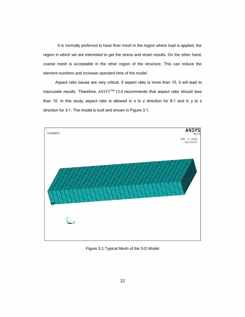
Aspect ratio issues are very critical, if aspect ratio is more than 15, it will lead to
inaccurate results. Therefore, recommends that aspect ratio should less
than 10. In this study, aspect ratio is allowed in x to z direction for 8:1 and in y to z
direction for 3:1. The model is built and shown in Figure 3.1.
Figure 3.1 Typical Mesh of the 3-D Model
33
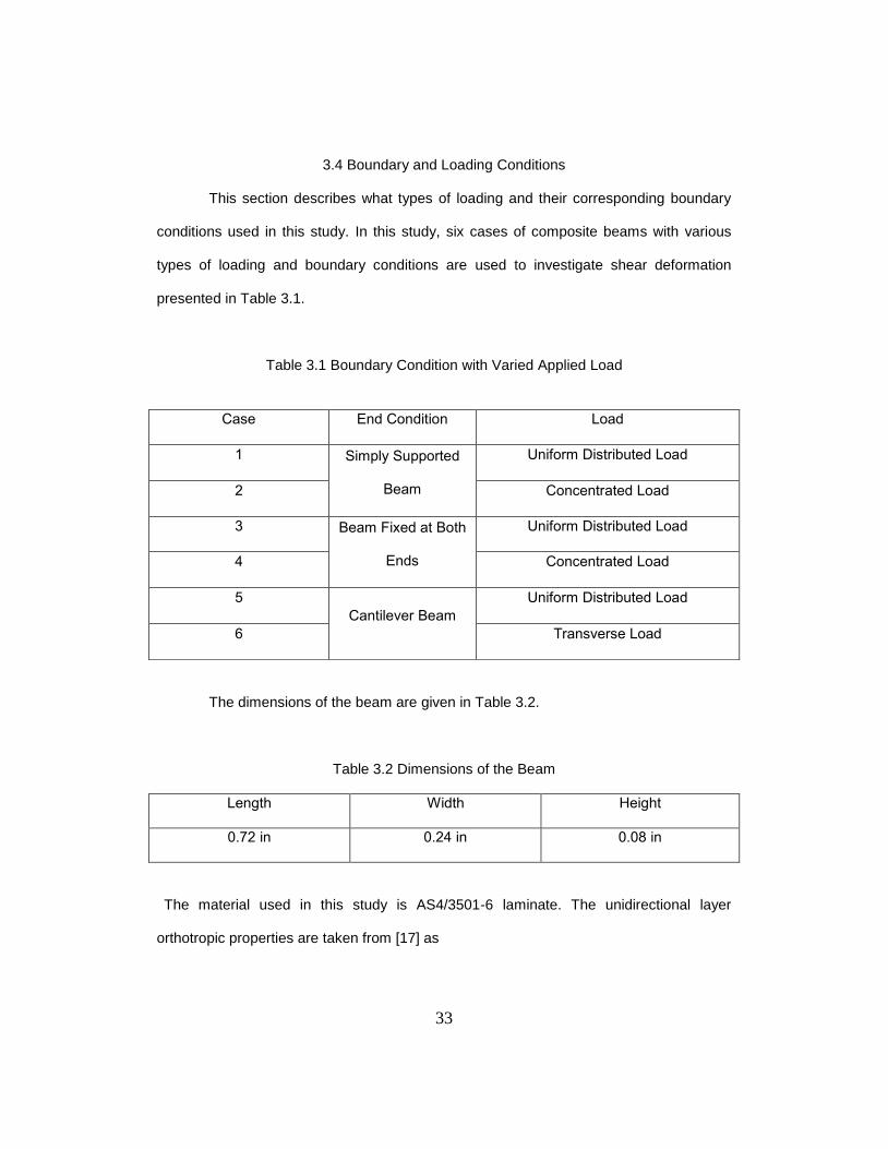
3.4 Boundary and Loading Conditions
This section describes what types of loading and their corresponding boundary
conditions used in this study. In this study, six cases of composite beams with various
types of loading and boundary conditions are used to investigate shear deformation
presented in Table 3.1.
Table 3.1 Boundary Condition with Varied Applied Load
The dimensions of the beam are given in Table 3.2.
Table 3.2 Dimensions of the Beam
Length Width Height
0.72 in 0.24 in 0.08 in
The material used in this study is AS4/3501-6 laminate. The unidirectional layer
orthotropic properties are taken from [17] as
Case End Condition Load
1 Simply Supported
Beam
Uniform Distributed Load
2 Concentrated Load
3 Beam Fixed at Both
Ends
Uniform Distributed Load
4 Concentrated Load
5
Cantilever Beam
Uniform Distributed Load
6 Transverse Load
34
where are the Young’s moduli of the composite lamina along the material
coordinates. are the shear moduli and are Poisson’s ratio
with respect to the 1-2, 2-3, and 1-3 planes, respectively and is the cured ply
thickness.
3.5 Composite Beam Modeling in ANSYS
ANSYS Classic (APDL) version 15.0 is used to carry out all the FEM modeling and
solution in this thesis. Simply step are used to model the composite/isotropic beam with
varied boundary conditions and applied loads. Details are as follows:
Define Element Type
3-D Solid186 is used for modeling the composite beam. 2-D elements are not
selected because out-plane shear deformation is considered.
Define Material type
Orthotropic properties are defined so the same model can be both verified
isotropic and composite model by adjusting the material properties.
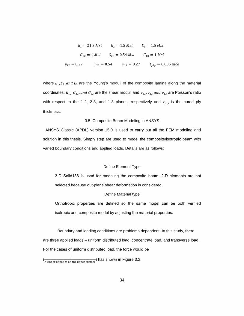
Boundary and loading conditions are problems dependent. In this study, there
are three applied loads – uniform distributed load, concentrate load, and transverse load.
For the cases of uniform distributed load, the force would be
(
) has shown in Figure 3.2.
35
Figure 3.2 Uniform Distributed Load on Top Surface of the Laminate
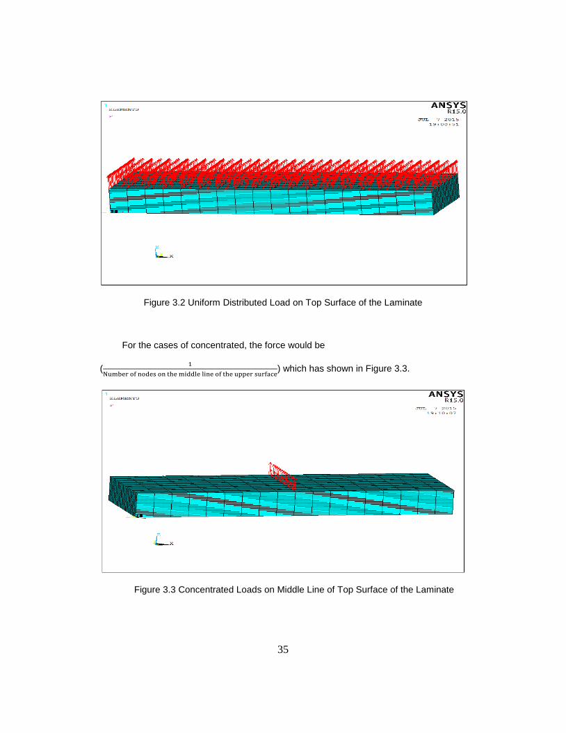
For the cases of concentrated, the force would be
(
) which has shown in Figure 3.3.
Figure 3.3 Concentrated Loads on Middle Line of Top Surface of the Laminate
36
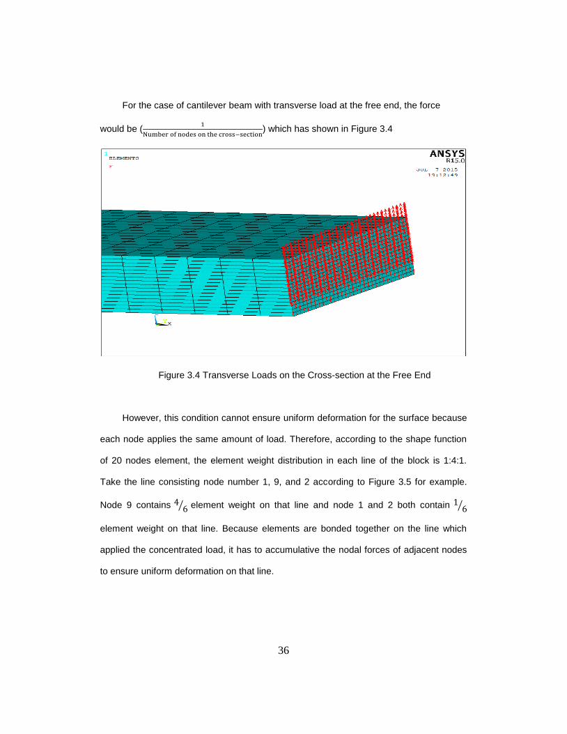
For the case of cantilever beam with transverse load at the free end, the force
would be (
) which has shown in Figure 3.4
Figure 3.4 Transverse Loads on the Cross-section at the Free End
However, this condition cannot ensure uniform deformation for the surface because
each node applies the same amount of load. Therefore, according to the shape function
of 20 nodes element, the element weight distribution in each line of the block is 1:4:1.
Take the line consisting node number 1, 9, and 2 according to Figure 3.5 for example.
Node 9 contains ⁄ element weight on that line and node 1 and 2 both contain ⁄
element weight on that line. Because elements are bonded together on the line which
applied the concentrated load, it has to accumulative the nodal forces of adjacent nodes
to ensure uniform deformation on that line.
37
Figure 3.5 Solid186 Element
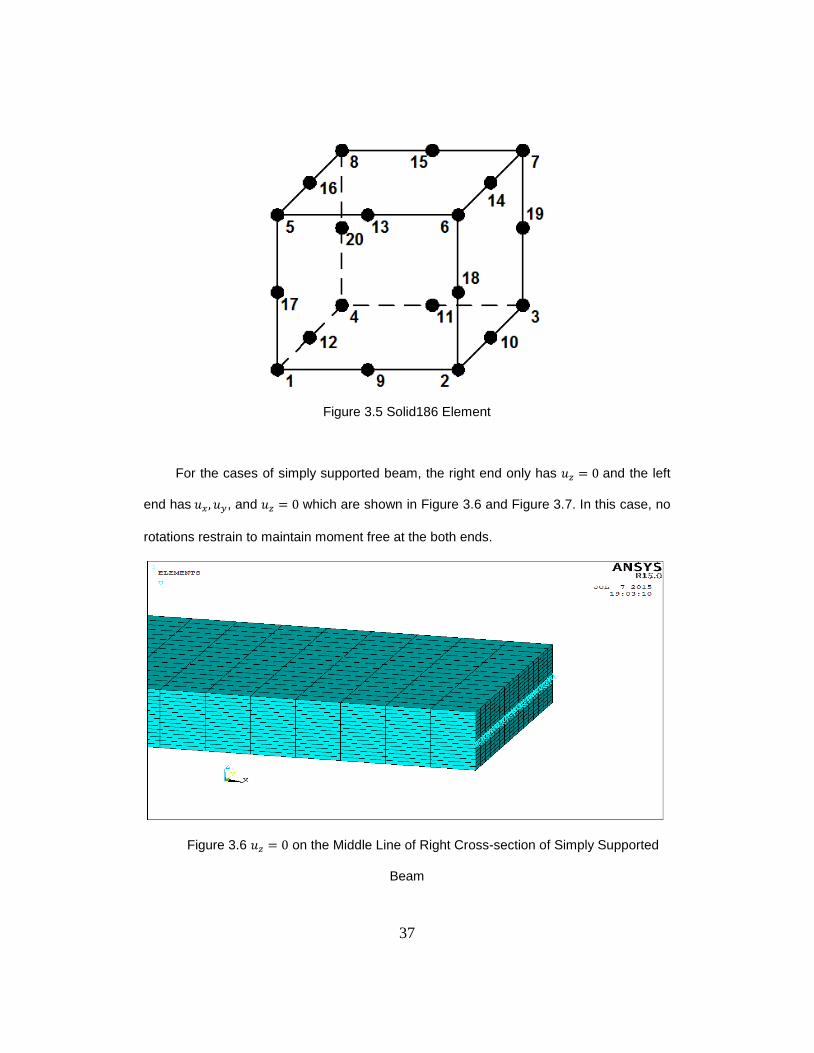
For the cases of simply supported beam, the right end only has and the left
end has , and which are shown in Figure 3.6 and Figure 3.7. In this case, no
rotations restrain to maintain moment free at the both ends.
Figure 3.6 on the Middle Line of Right Cross-section of Simply Supported
Beam
38
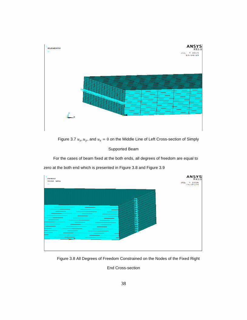
Figure 3.7 , and on the Middle Line of Left Cross-section of Simply
Supported Beam
For the cases of beam fixed at the both ends, all degrees of freedom are equal to
zero at the both end which is presented in Figure 3.8 and Figure 3.9
Figure 3.8 All Degrees of Freedom Constrained on the Nodes of the Fixed Right
End Cross-section
39
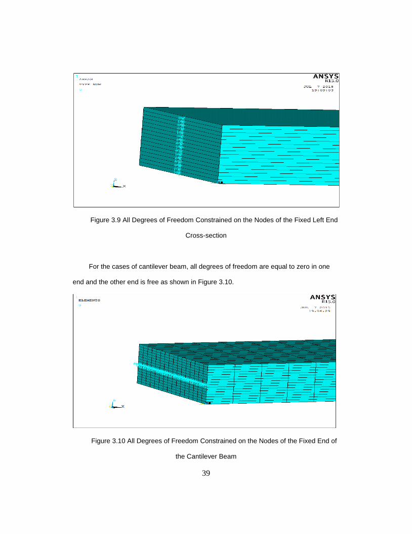
Figure 3.9 All Degrees of Freedom Constrained on the Nodes of the Fixed Left End
Cross-section
For the cases of cantilever beam, all degrees of freedom are equal to zero in one
end and the other end is free as shown in Figure 3.10.
Figure 3.10 All Degrees of Freedom Constrained on the Nodes of the Fixed End of
the Cantilever Beam
40
3.6 Verification of Finite Element Model
It is important to verify the accuracy of the model before employing composite
models. Verification of the finite element model is based on comparison between the
maximum deflection of the isotropic beam which is obtained from the finite element model
and the results derived from the classical beam equations with shear deformation are
shown in Table 3.3. The isotropic material used in this study is aluminum. The material
properties, beam geometry, and load magnitude are given as follow.
𝑃
⁄
where E is the Young’s modulus , and is Poisson’s ratio.
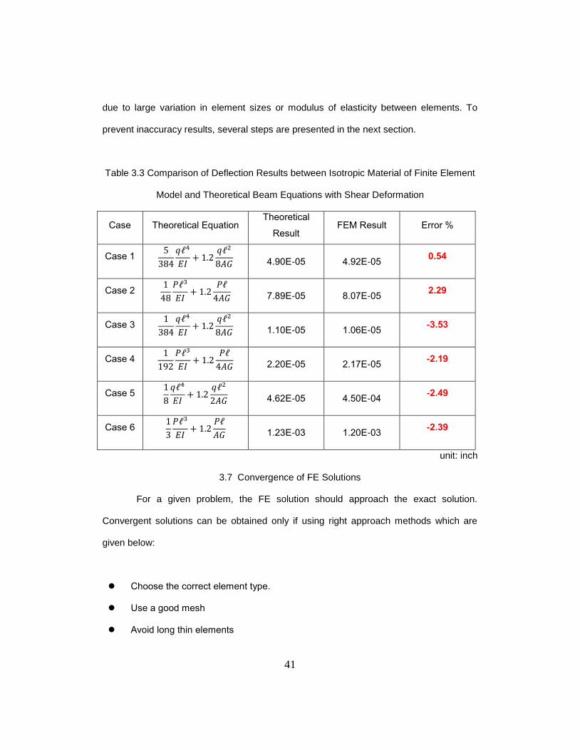
Since all finite element results agree with theoretical isotropic beam equations
with shear deformation, the present models are valid for investigating the composite
beams.
Becker [18] stated that there are several errors would influence the accuracy of
the model. First of all, modelling errors occur if the geometry is not exactly modelled or
the boundary conditions are not accurately interpreted. Moreover, mesh errors may occur
in “not good” mesh. If the element is thin and long, inaccuracy results will be obtained.
Lastly, numerical errors may occur due to round-off in the computations, where numbers
are truncated due to insufficient digits being used in the calculations. Some problems are
very sensitive to small changes which are called ill-conditioned. This will occur when the
stiffness matrix contains coefficients of varying orders of magnitudes in the same row,
41
due to large variation in element sizes or modulus of elasticity between elements. To
prevent inaccuracy results, several steps are presented in the next section.
Table 3.3 Comparison of Deflection Results between Isotropic Material of Finite Element
Model and Theoretical Beam Equations with Shear Deformation
Case Theoretical Equation Theoretical
Result FEM Result Error %
Case 1
𝐼
4.90E-05 4.92E-05
0.54
Case 2
𝑃
𝐼
𝑃
7.89E-05 8.07E-05
2.29
Case 3
𝐼
1.10E-05 1.06E-05
-3.53
Case 4
𝑃
𝐼
𝑃
2.20E-05 2.17E-05
-2.19
Case 5
𝐼
4.62E-05 4.50E-04
-2.49
Case 6
𝑃
𝐼
𝑃
1.23E-03 1.20E-03
-2.39
unit: inch
3.7 Convergence of FE Solutions
For a given problem, the FE solution should approach the exact solution.
Convergent solutions can be obtained only if using right approach methods which are
given below:
Choose the correct element type.
Use a good mesh
Avoid long thin elements
42
Check stress accuracy
Prevent rigid body motion
Check reaction forces
Ensure inter-element connectivity
Check the text output of the FE software
The detail information can be found from Becker [18].
Cantilever beam under concentrated load at the free end with
laminate is selected for this convergence study, where the material properties, beam
geometry are presented in section 3.4, and load magnitude is presented in section 3.6.
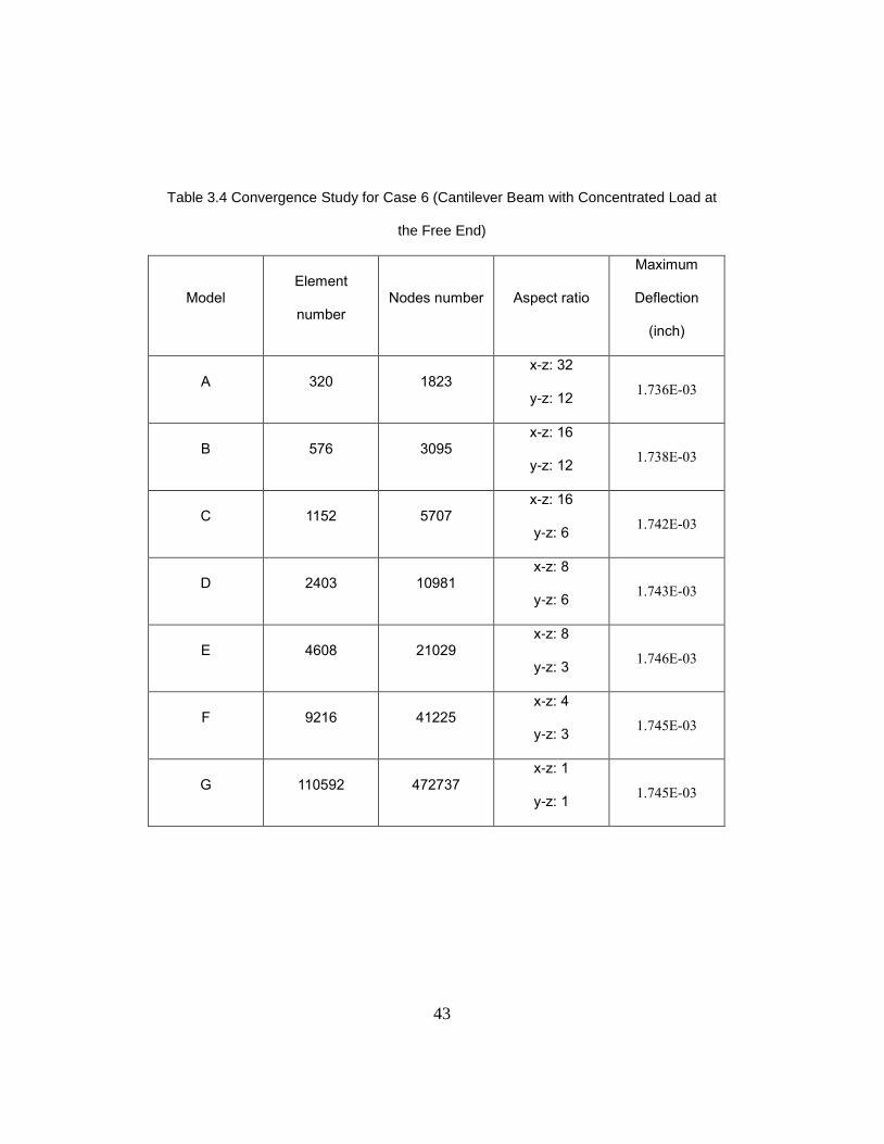
It is often difficult to establish the optimum mesh refinement needed for an FE
model. One way of checking that the FE mesh used is a reasonable one to start from a
relatively coarse mesh, and then refine it. If solutions display large errors, further mesh
refinement may be needed. According to Table 3.4, the maximum displacement of
cantilever beam with transverse load at the free end is close to 1.745 with increasing
element numbers. The model is validated by convergence study.
The interesting observation is that the convergent speed is faster when aspect
ratio in thickness direction decreases. On the other hand, even though the aspect ratio in
longitudinal direction decreases, the convergent speed of the result is still slower than the
speed in decreasing aspect ratio in thickness. Due to large transverse shear deformation
induced in composite laminates when applying the bending moment Mx, decreasing the
aspect ratio in thickness direction will influence the result significantly. On the other hand,
if the axial load is applied, then the aspect ratio in longitudinal direction will influence the
convergent speed quickly.
43
Table 3.4 Convergence Study for Case 6 (Cantilever Beam with Concentrated Load at
the Free End)
Model Element
number Nodes number Aspect ratio
Maximum
Deflection
(inch)
A 320 1823 x-z: 32
y-z: 12 1.736E-03
B 576 3095 x-z: 16
y-z: 12 1.738E-03
C 1152 5707 x-z: 16
y-z: 6 1.742E-03
D 2403 10981 x-z: 8
y-z: 6 1.743E-03
E 4608 21029 x-z: 8
y-z: 3 1.746E-03
F 9216 41225 x-z: 4
y-z: 3 1.745E-03
G 110592 472737 x-z: 1
y-z: 1 1.745E-03
44
Chapter 4
Results and Discussion
In this chapter, different laminated composite beams with different stacking
sequences, boundary conditions, and applied loads were conducted to investigate effects
of transverse shear deformation. In addition, two different expressions of bending
stiffness for composite laminated beams are used. The comparison between the
maximum deflections of the finite element results and analytical solutions are presented.
4.1 Effects of Boundary Conditions
In this part, the beam laminate is allowed to twist when the load is applied. If the
laminates can be twisted, there exists no the moment For this case, the bending
stiffness of the laminate is
.
The deflection equations of the beams are listed in Table 2.2. The corresponding
boundary conditions of each beam are tabulated in Table 2.1. In this part, shear
deformations divided by total deformations for different laminates and boundary
conditions are investigated. In addition, comparisons between theoretical and ANSYS
results are presented below.
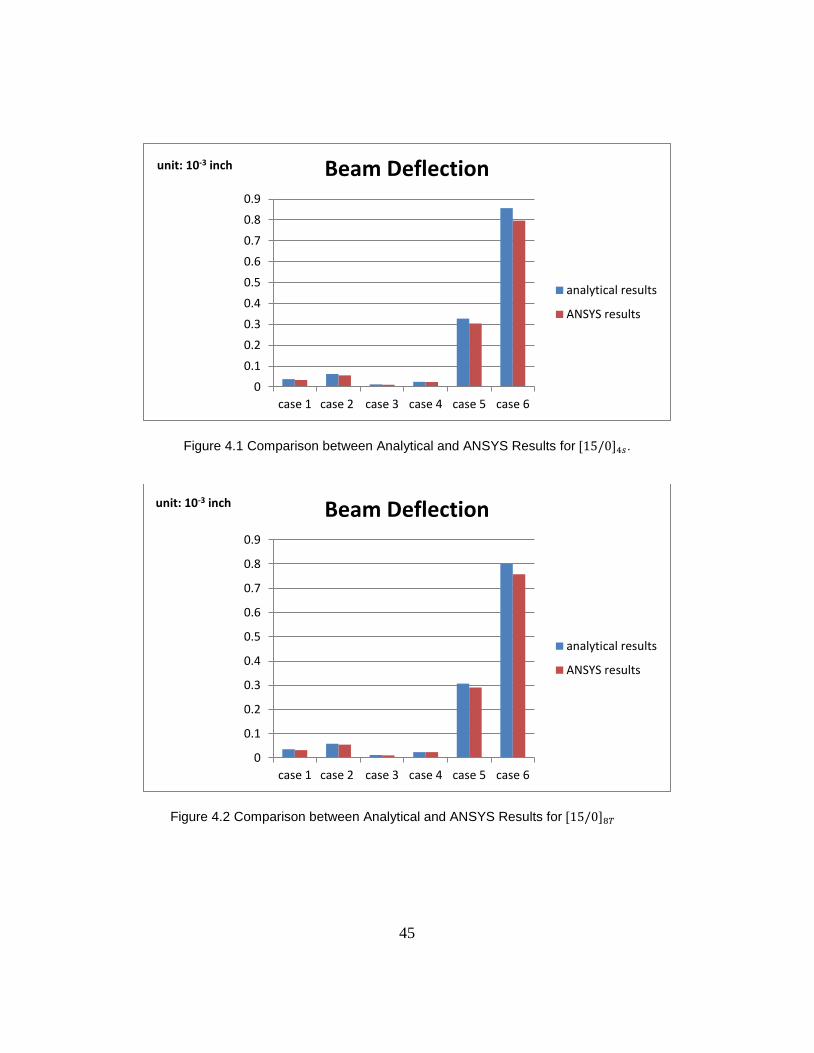
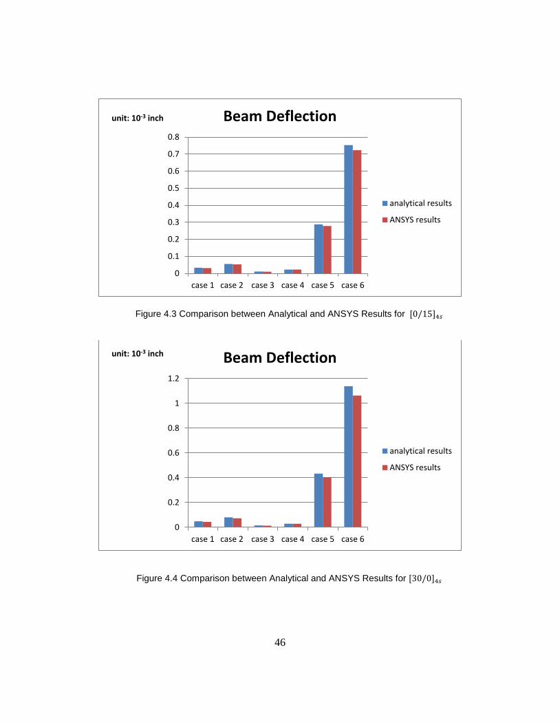
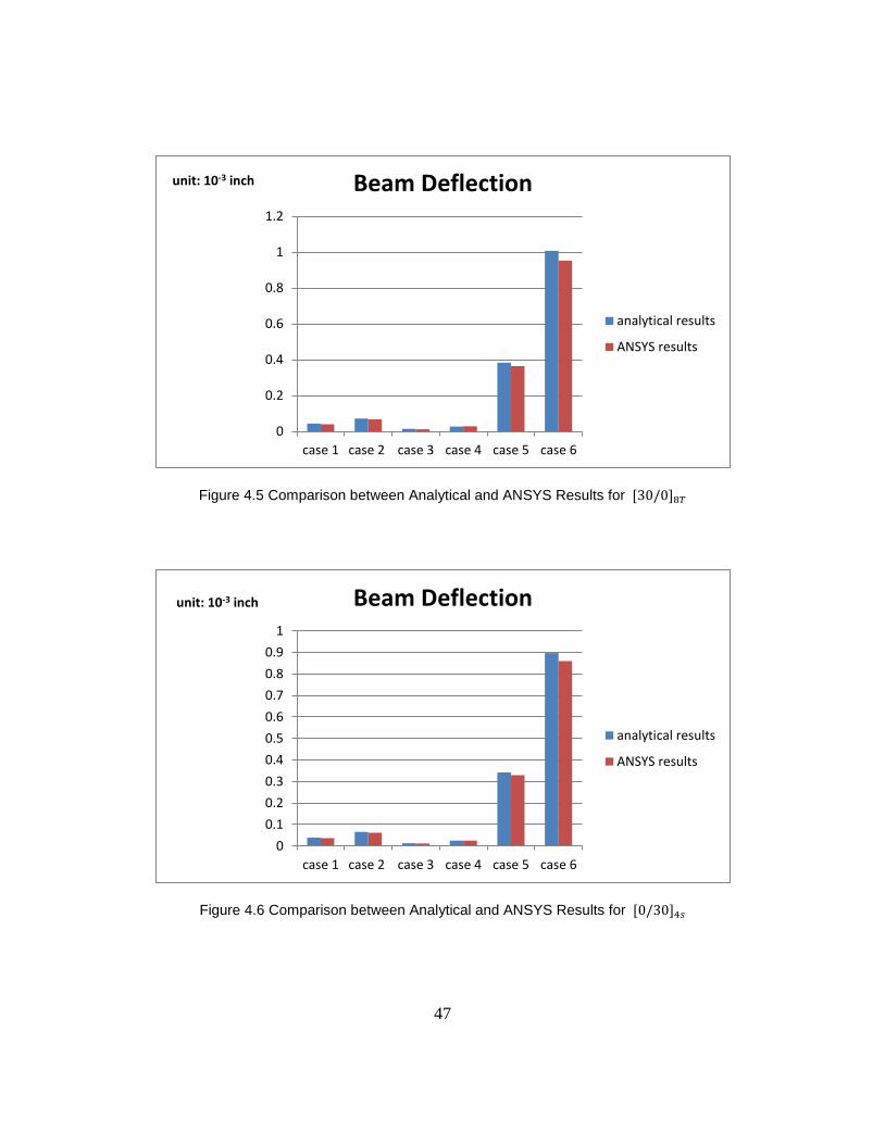
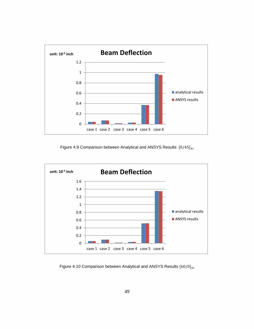
Figure 4.1 through 4.15 shows a comparison of the total beam deflection results
obtained by analytical model and ANSYS method. Case 1 through case6 used in this
study is referred as, simply supported beam (case 1 and 2), beam fixed both end (case 3
and 4) and the cantilevered beam (case 5 and 6). Each beam is subjected to uniformly
and concentrated transverse load. These are listed in Table 3.1. The results indicate that
both results agree well each other. The result discussion will be given at the end of the
figures.
45
Figure 4.1 Comparison between Analytical and ANSYS Results for .
Figure 4.2 Comparison between Analytical and ANSYS Results for
0
0.1
0.2
0.3
0.4
0.5
0.6
0.7
0.8
0.9
case 1 case 2 case 3 case 4 case 5 case 6
unit: 10-3 inch Beam Deflection
analytical results
ANSYS results
0
0.1
0.2
0.3
0.4
0.5
0.6
0.7
0.8
0.9
case 1 case 2 case 3 case 4 case 5 case 6
unit: 10-3 inch Beam Deflection
analytical results
ANSYS results
46
Figure 4.3 Comparison between Analytical and ANSYS Results for
Figure 4.4 Comparison between Analytical and ANSYS Results for
0
0.1
0.2
0.3
0.4
0.5
0.6
0.7
0.8
case 1 case 2 case 3 case 4 case 5 case 6
unit: 10-3 inch Beam Deflection
analytical results
ANSYS results
0
0.2
0.4
0.6
0.8
1
1.2
case 1 case 2 case 3 case 4 case 5 case 6
unit: 10-3 inch Beam Deflection
analytical results
ANSYS results
47
Figure 4.5 Comparison between Analytical and ANSYS Results for
Figure 4.6 Comparison between Analytical and ANSYS Results for
0
0.2
0.4
0.6
0.8
1
1.2
case 1 case 2 case 3 case 4 case 5 case 6
unit: 10-3 inch Beam Deflection
analytical results
ANSYS results
0
0.1
0.2
0.3
0.4
0.5
0.6
0.7
0.8
0.9
1
case 1 case 2 case 3 case 4 case 5 case 6
unit: 10-3 inch Beam Deflection
analytical results
ANSYS results

48
Figure 4.7 Comparison between Analytical and ANSYS Results for
Figure 4.8 Comparison between Analytical and ANSYS Results
0
0.2
0.4
0.6
0.8
1
1.2
1.4
case 1 case 2 case 3 case 4 case 5 case 6
unit: 10-3 inch Beam Deflection
analytical results
ANSYS results
0
0.2
0.4
0.6
0.8
1
1.2
case 1 case 2 case 3 case 4 case 5 case 6
unit: 10-3 inch Beam Deflection
analytical results
ANSYS results
49
Figure 4.9 Comparison between Analytical and ANSYS Results
Figure 4.10 Comparison between Analytical and ANSYS Results
0
0.2
0.4
0.6
0.8
1
1.2
case 1 case 2 case 3 case 4 case 5 case 6
unit: 10-3 inch Beam Deflection
analytical results
ANSYS results
0
0.2
0.4
0.6
0.8
1
1.2
1.4
1.6
case 1 case 2 case 3 case 4 case 5 case 6
unit: 10-3 inch Beam Deflection
analytical results
ANSYS results
50
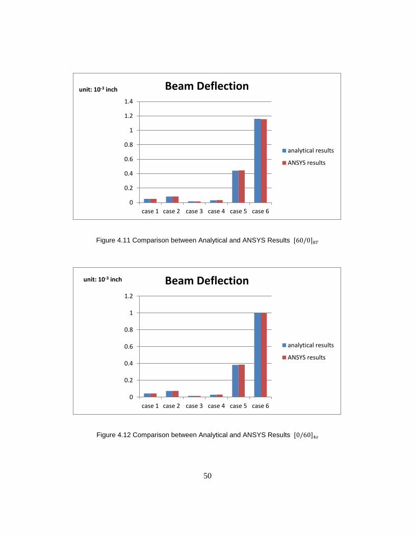
Figure 4.11 Comparison between Analytical and ANSYS Results
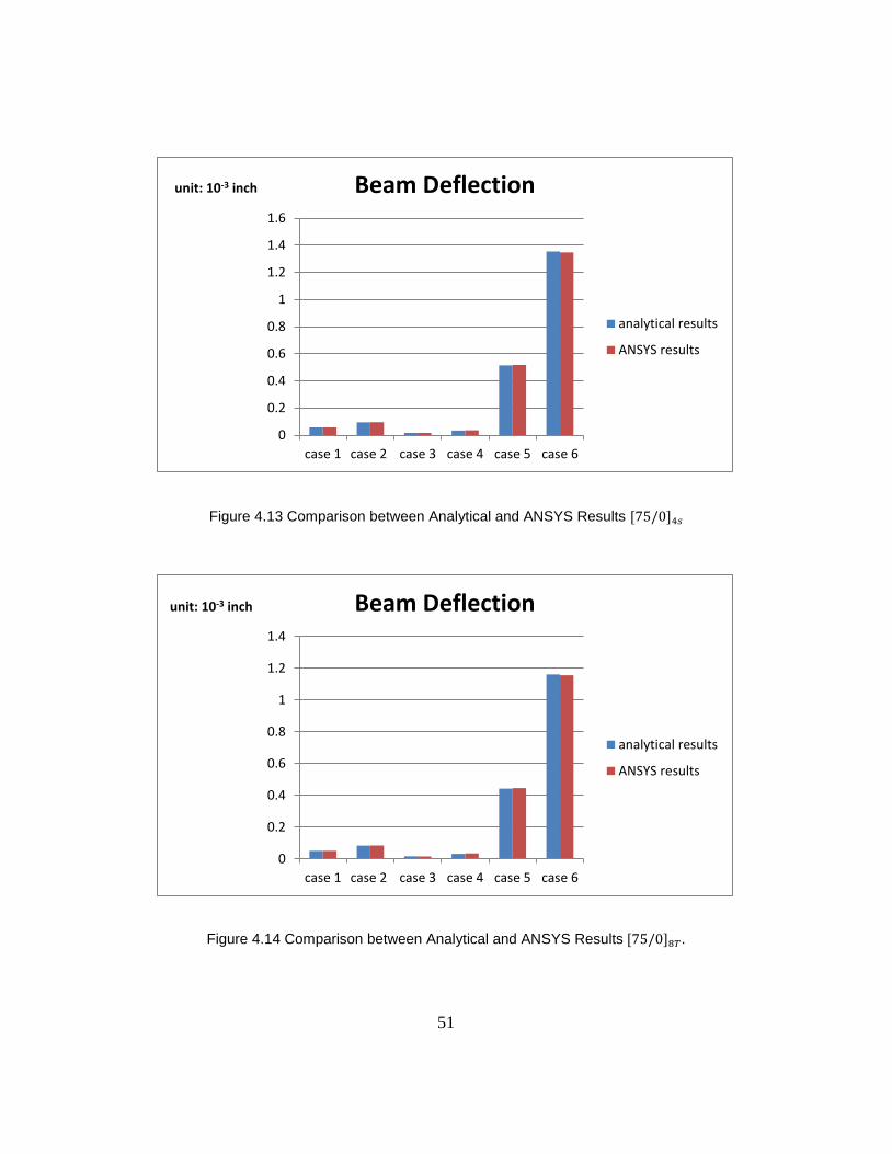
Figure 4.12 Comparison between Analytical and ANSYS Results
0
0.2
0.4
0.6
0.8
1
1.2
1.4
case 1 case 2 case 3 case 4 case 5 case 6
unit: 10-3 inch Beam Deflection
analytical results
ANSYS results
0
0.2
0.4
0.6
0.8
1
1.2
case 1 case 2 case 3 case 4 case 5 case 6
unit: 10-3 inch Beam Deflection
analytical results
ANSYS results
51
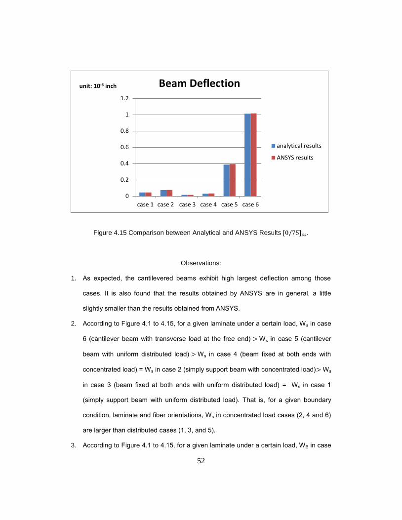
Figure 4.13 Comparison between Analytical and ANSYS Results
Figure 4.14 Comparison between Analytical and ANSYS Results .
0
0.2
0.4
0.6
0.8
1
1.2
1.4
1.6
case 1 case 2 case 3 case 4 case 5 case 6
unit: 10-3 inch Beam Deflection
analytical results
ANSYS results
0
0.2
0.4
0.6
0.8
1
1.2
1.4
case 1 case 2 case 3 case 4 case 5 case 6
unit: 10-3 inch Beam Deflection
analytical results
ANSYS results
52
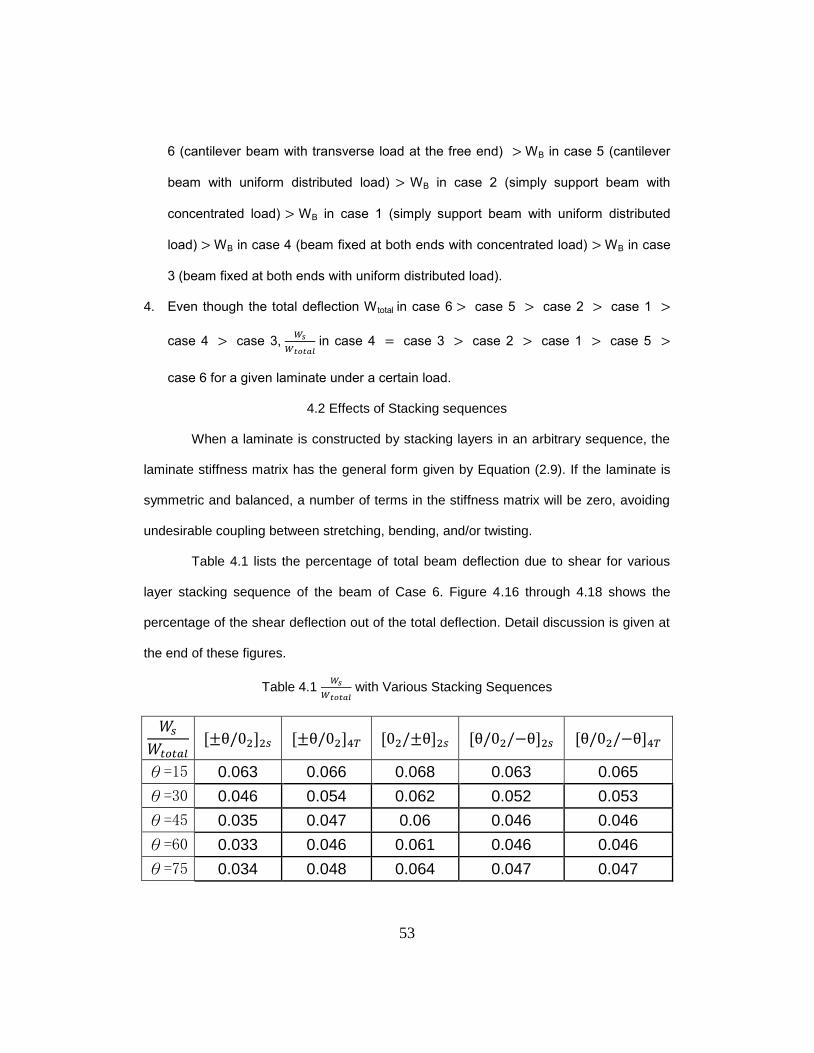
Figure 4.15 Comparison between Analytical and ANSYS Results .
Observations:
1. As expected, the cantilevered beams exhibit high largest deflection among those
cases. It is also found that the results obtained by ANSYS are in general, a little
slightly smaller than the results obtained from ANSYS.
2. According to Figure 4.1 to 4.15, for a given laminate under a certain load, Ws in case
6 (cantilever beam with transverse load at the free end) > Ws in case 5 (cantilever
beam with uniform distributed load) > Ws in case 4 (beam fixed at both ends with
concentrated load) = Ws in case 2 (simply support beam with concentrated load)> Ws
in case 3 (beam fixed at both ends with uniform distributed load) = Ws in case 1
(simply support beam with uniform distributed load). That is, for a given boundary
condition, laminate and fiber orientations, Ws in concentrated load cases (2, 4 and 6)
are larger than distributed cases (1, 3, and 5).
3. According to Figure 4.1 to 4.15, for a given laminate under a certain load, WB in case
0
0.2
0.4
0.6
0.8
1
1.2
case 1 case 2 case 3 case 4 case 5 case 6
unit: 10-3 inch Beam Deflection
analytical results
ANSYS results
53
6 (cantilever beam with transverse load at the free end) > WB in case 5 (cantilever
beam with uniform distributed load) > WB in case 2 (simply support beam with
concentrated load) > WB in case 1 (simply support beam with uniform distributed
load) > WB in case 4 (beam fixed at both ends with concentrated load) > WB in case
3 (beam fixed at both ends with uniform distributed load).
4. Even though the total deflection W total in case 6 > case 5 > case 2 > case 1 >
case 4 > case 3,
in case 4 case 3 > case 2 > case 1 > case 5 >
case 6 for a given laminate under a certain load.
4.2 Effects of Stacking sequences
When a laminate is constructed by stacking layers in an arbitrary sequence, the
laminate stiffness matrix has the general form given by Equation (2.9). If the laminate is
symmetric and balanced, a number of terms in the stiffness matrix will be zero, avoiding
undesirable coupling between stretching, bending, and/or twisting.
Table 4.1 lists the percentage of total beam deflection due to shear for various
layer stacking sequence of the beam of Case 6. Figure 4.16 through 4.18 shows the
percentage of the shear deflection out of the total deflection. Detail discussion is given at
the end of these figures.
Table 4.1
with Various Stacking Sequences
θ=15 0.063 0.066 0.068 0.063 0.065
θ=30 0.046 0.054 0.062 0.052 0.053
θ=45 0.035 0.047 0.06 0.046 0.046
θ=60 0.033 0.046 0.061 0.046 0.046
θ=75 0.034 0.048 0.064 0.047 0.047
54
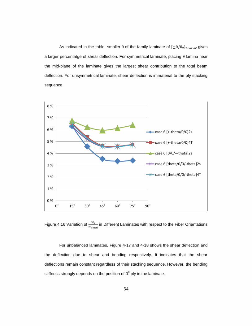
As indicated in the table, smaller of the family laminate of gives
a larger percentatge of shear deflection. For symmetrical laminate, placing lamina near
the mid-plane of the laminate gives the largest shear contribution to the total beam
deflection. For unsymmetrical laminate, shear deflection is immaterial to the ply stacking
sequence.
Figure 4.16 Variation of
in Different Laminates with respect to the Fiber Orientations
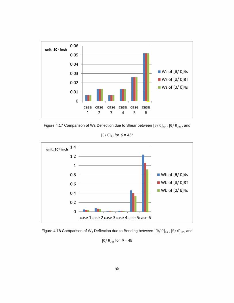
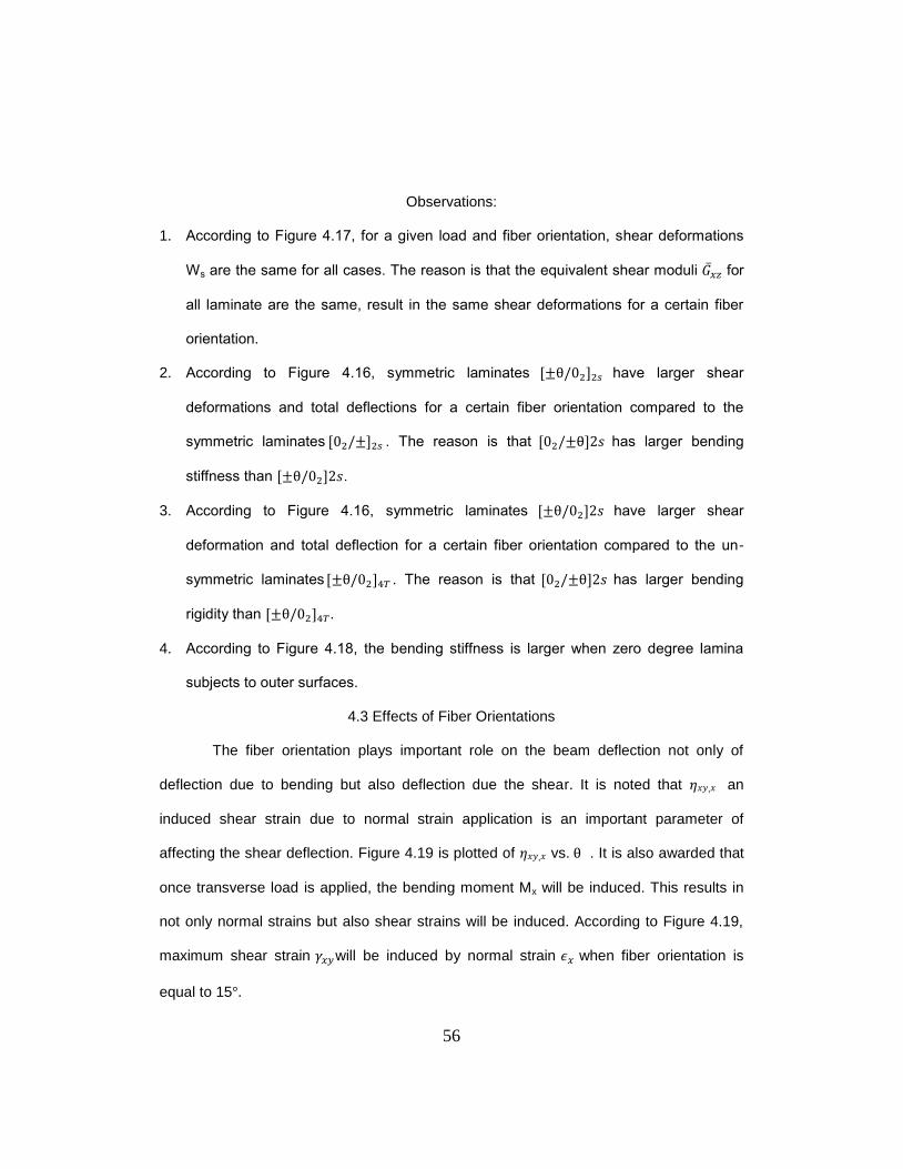
For unbalanced laminates, Figure 4-17 and 4-18 shows the shear deflection and
the deflection due to shear and bending respectively. It indicates that the shear
deflections remain constant regardless of their stacking sequence. However, the bending
stiffness strongly depends on the position of 00 ply in the laminate.
0 %
1 %
2 %
3 %
4 %
5 %
6 %
7 %
8 %
0° 15° 30° 45° 60° 75° 90°
case 6 [+-theta/0/0]2s
case 6 [+-theta/0/0]4T
case 6 [0/0/+-theta]2s
case 6 [theta/0/0/-theta]2s
case 6 [theta/0/0/-theta]4T
55
Figure 4.17 Comparison of Ws Deflection due to Shear between , , and
for θ= 45
Figure 4.18 Comparison of Wb Deflection due to Bending between , , and
for θ= 45
0
0.01
0.02
0.03
0.04
0.05
0.06
case1
case2
case3
case4
case5
case6
unit: 10-3 inch
Ws of [θ/ 0]4s
Ws of [θ/ 0]8T
Ws of [0/ θ]4s
0
0.2
0.4
0.6
0.8
1
1.2
1.4
case 1case 2 case 3case 4case 5case 6
unit: 10-3 inch
Wb of [θ/ 0]4s
Wb of [θ/ 0]8T
Wb of [0/ θ]4s
56
Observations:
1. According to Figure 4.17, for a given load and fiber orientation, shear deformations
Ws are the same for all cases. The reason is that the equivalent shear moduli for
all laminate are the same, result in the same shear deformations for a certain fiber
orientation.
2. According to Figure 4.16, symmetric laminates have larger shear
deformations and total deflections for a certain fiber orientation compared to the
symmetric laminates . The reason is that has larger bending
stiffness than .
3. According to Figure 4.16, symmetric laminates have larger shear
deformation and total deflection for a certain fiber orientation compared to the un-
symmetric laminates . The reason is that has larger bending
rigidity than .
4. According to Figure 4.18, the bending stiffness is larger when zero degree lamina
subjects to outer surfaces.
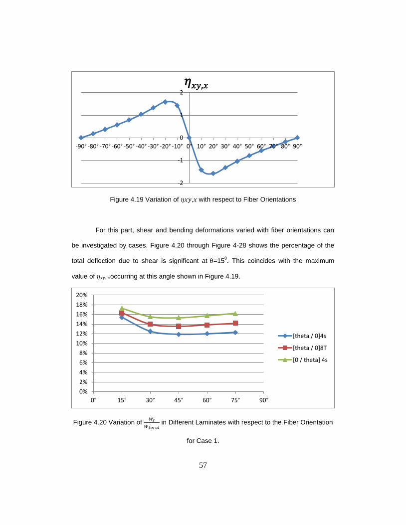
4.3 Effects of Fiber Orientations
The fiber orientation plays important role on the beam deflection not only of
deflection due to bending but also deflection due the shear. It is noted that 𝜂𝑥𝑦,𝑥 an
induced shear strain due to normal strain application is an important parameter of
affecting the shear deflection. Figure 4.19 is plotted of 𝜂𝑥𝑦,𝑥 vs. . It is also awarded that
once transverse load is applied, the bending moment Mx will be induced. This results in
not only normal strains but also shear strains will be induced. According to Figure 4.19,
maximum shear strain will be induced by normal strain when fiber orientation is
equal to 15 .
57
Figure 4.19 Variation of 𝜂𝑥𝑦,𝑥 with respect to Fiber Orientations
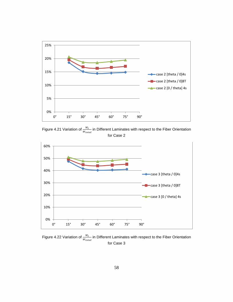
For this part, shear and bending deformations varied with fiber orientations can
be investigated by cases. Figure 4.20 through Figure 4-28 shows the percentage of the
total deflection due to shear is significant at =150. This coincides with the maximum
value of 𝜂𝑥𝑦, 𝑥occurring at this angle shown in Figure 4.19.
Figure 4.20 Variation of
in Different Laminates with respect to the Fiber Orientation
for Case 1.
-2
-1
0
1
2
-90°-80°-70°-60°-50°-40°-30°-20°-10° 0° 10° 20° 30° 40° 50° 60° 70° 80° 90°
𝜂𝑥𝑦,𝑥
0%
2%
4%
6%
8%
10%
12%
14%
16%
18%
20%
0° 15° 30° 45° 60° 75° 90°
[theta / 0]4s
[theta / 0]8T
[0 / theta] 4s
58
Figure 4.21 Variation of
in Different Laminates with respect to the Fiber Orientation
for Case 2
Figure 4.22 Variation of
in Different Laminates with respect to the Fiber Orientation
for Case 3
0%
5%
10%
15%
20%
25%
0° 15° 30° 45° 60° 75° 90°
case 2 [theta / 0]4s
case 2 [theta / 0]8T
case 2 [0 / theta] 4s
0%
10%
20%
30%
40%
50%
60%
0° 15° 30° 45° 60° 75° 90°
case 3 [theta / 0]4s
case 3 [theta / 0]8T
case 3 [0 / theta] 4s
59
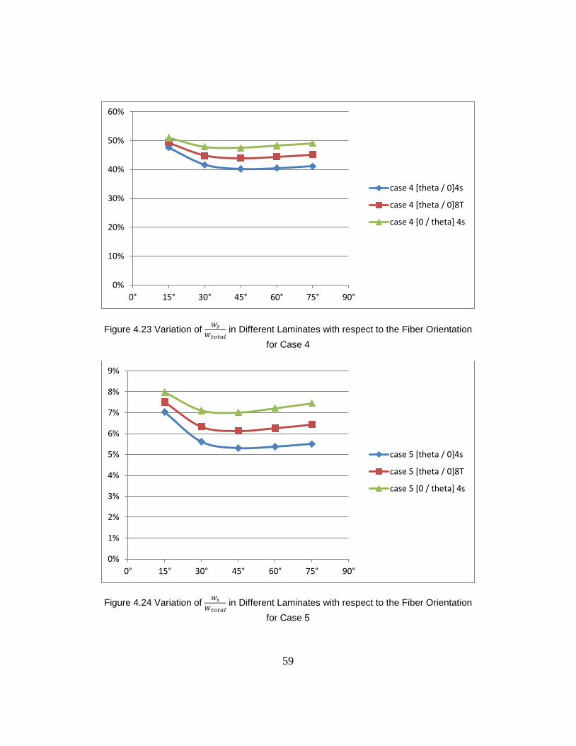
Figure 4.23 Variation of
in Different Laminates with respect to the Fiber Orientation
for Case 4
Figure 4.24 Variation of
in Different Laminates with respect to the Fiber Orientation
for Case 5
0%
10%
20%
30%
40%
50%
60%
0° 15° 30° 45° 60° 75° 90°
case 4 [theta / 0]4s
case 4 [theta / 0]8T
case 4 [0 / theta] 4s
0%
1%
2%
3%
4%
5%
6%
7%
8%
9%
0° 15° 30° 45° 60° 75° 90°
case 5 [theta / 0]4s
case 5 [theta / 0]8T
case 5 [0 / theta] 4s
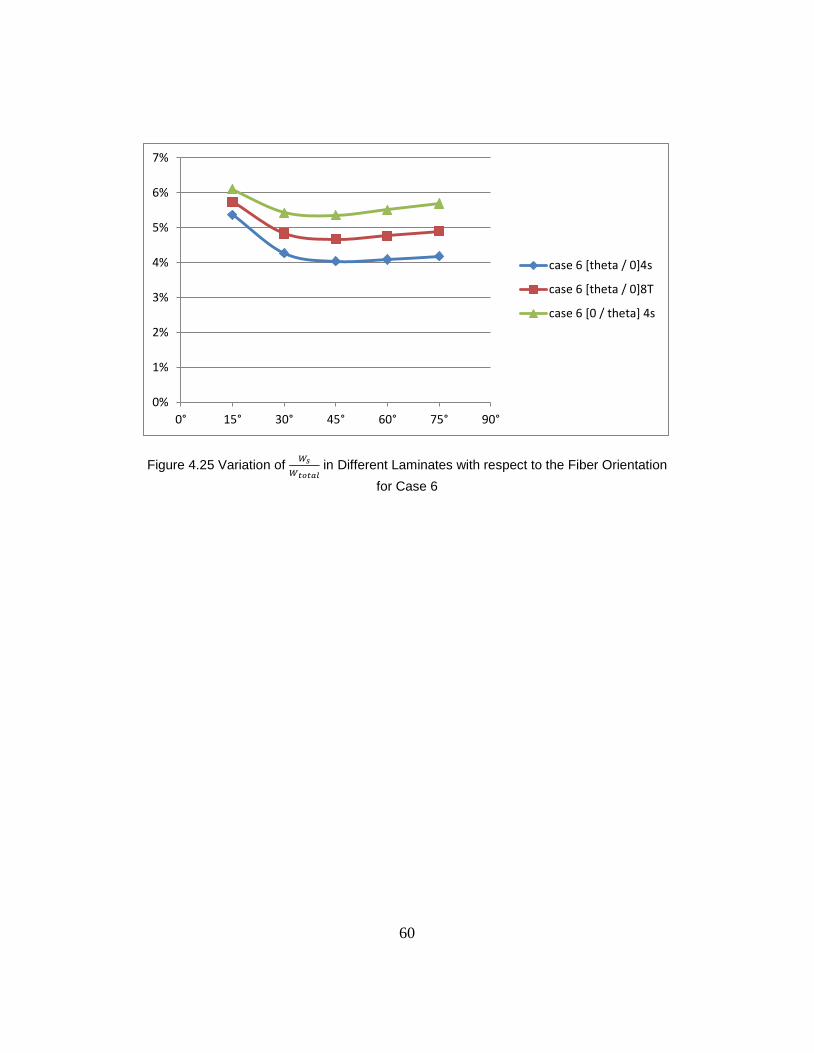
60
Figure 4.25 Variation of
in Different Laminates with respect to the Fiber Orientation
for Case 6
0%
1%
2%
3%
4%
5%
6%
7%
0° 15° 30° 45° 60° 75° 90°
case 6 [theta / 0]4s
case 6 [theta / 0]8T
case 6 [0 / theta] 4s
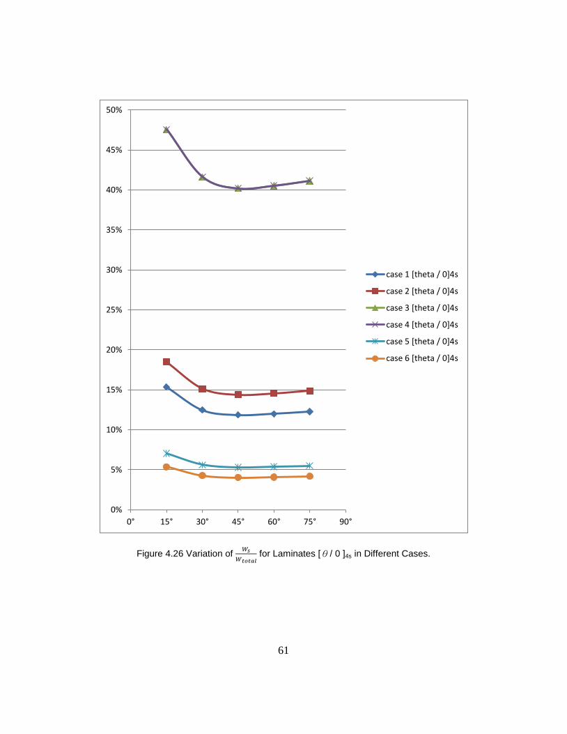
61
Figure 4.26 Variation of
for Laminates [θ/ 0 ]4s in Different Cases.
0%
5%
10%
15%
20%
25%
30%
35%
40%
45%
50%
0° 15° 30° 45° 60° 75° 90°
case 1 [theta / 0]4s
case 2 [theta / 0]4s
case 3 [theta / 0]4s
case 4 [theta / 0]4s
case 5 [theta / 0]4s
case 6 [theta / 0]4s
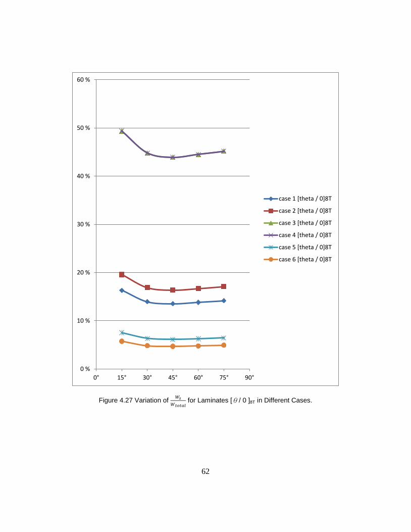
62
Figure 4.27 Variation of
for Laminates [θ/ 0 ]8T in Different Cases.
0 %
10 %
20 %
30 %
40 %
50 %
60 %
0° 15° 30° 45° 60° 75° 90°
case 1 [theta / 0]8T
case 2 [theta / 0]8T
case 3 [theta / 0]8T
case 4 [theta / 0]8T
case 5 [theta / 0]8T
case 6 [theta / 0]8T
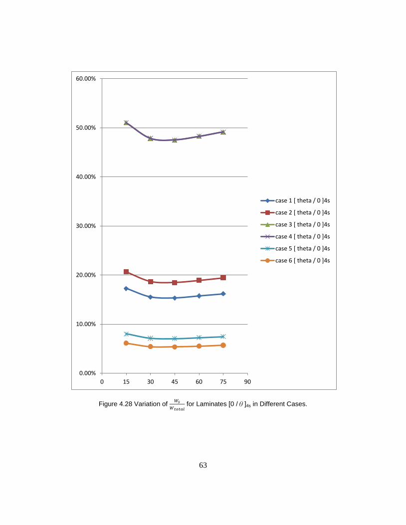
63
Figure 4.28 Variation of
for Laminates [0 /θ]4s in Different Cases.
0.00%
10.00%
20.00%
30.00%
40.00%
50.00%
60.00%
0 15 30 45 60 75 90
case 1 [ theta / 0 ]4s
case 2 [ theta / 0 ]4s
case 3 [ theta / 0 ]4s
case 4 [ theta / 0 ]4s
case 5 [ theta / 0 ]4s
case 6 [ theta / 0 ]4s
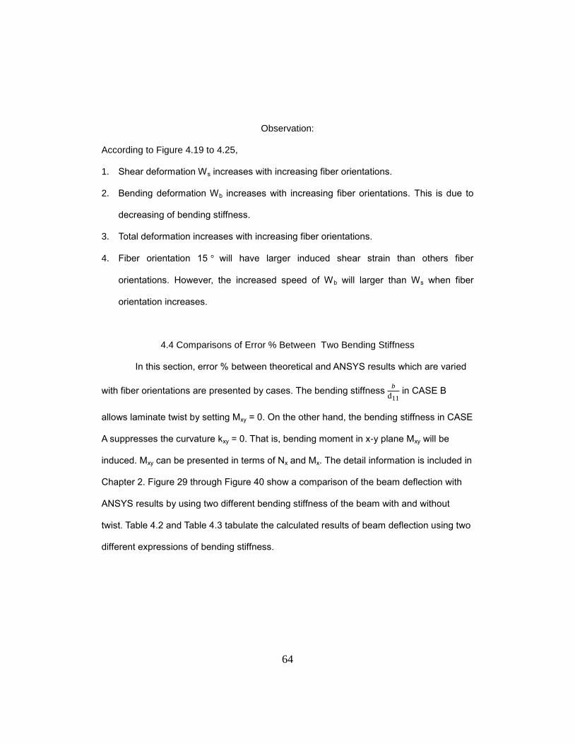
64
Observation:
According to Figure 4.19 to 4.25,
1. Shear deformation Ws increases with increasing fiber orientations.
2. Bending deformation Wb increases with increasing fiber orientations. This is due to
decreasing of bending stiffness.
3. Total deformation increases with increasing fiber orientations.
4. Fiber orientation 15 will have larger induced shear strain than others fiber
orientations. However, the increased speed of Wb will larger than Ws when fiber
orientation increases.
4.4 Comparisons of Error % Between Two Bending Stiffness
In this section, error % between theoretical and ANSYS results which are varied
with fiber orientations are presented by cases. The bending stiffness
in CASE B
allows laminate twist by setting Mxy = 0. On the other hand, the bending stiffness in CASE
A suppresses the curvature kxy = 0. That is, bending moment in x-y plane Mxy will be
induced. Mxy can be presented in terms of Nx and Mx. The detail information is included in
Chapter 2. Figure 29 through Figure 40 show a comparison of the beam deflection with
ANSYS results by using two different bending stiffness of the beam with and without
twist. Table 4.2 and Table 4.3 tabulate the calculated results of beam deflection using two
different expressions of bending stiffness.
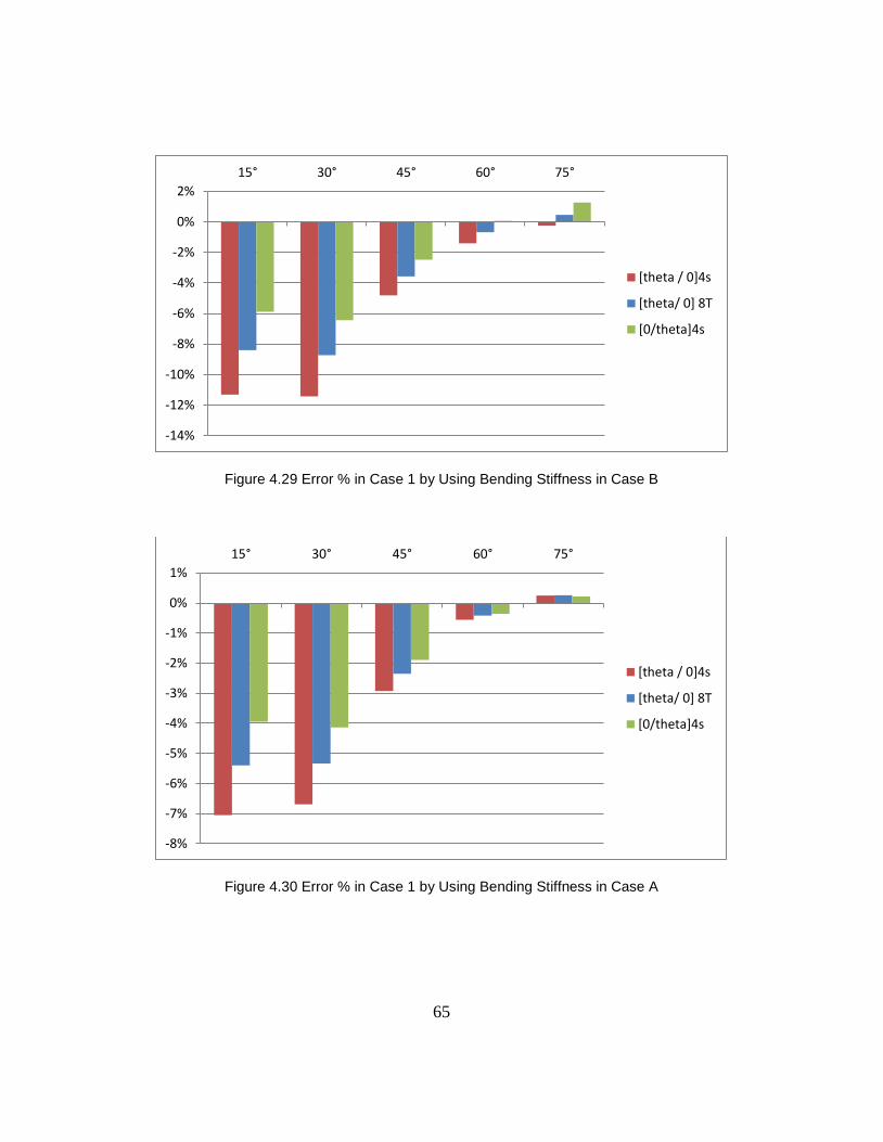
65
Figure 4.29 Error % in Case 1 by Using Bending Stiffness in Case B
Figure 4.30 Error % in Case 1 by Using Bending Stiffness in Case A
-14%
-12%
-10%
-8%
-6%
-4%
-2%
0%
2%
15° 30° 45° 60° 75°
[theta / 0]4s
[theta/ 0] 8T
[0/theta]4s
-8%
-7%
-6%
-5%
-4%
-3%
-2%
-1%
0%
1%
15° 30° 45° 60° 75°
[theta / 0]4s
[theta/ 0] 8T
[0/theta]4s
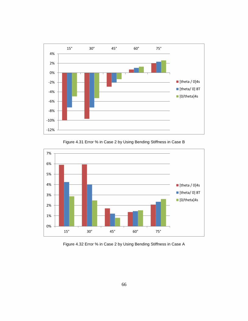
66
Figure 4.31 Error % in Case 2 by Using Bending Stiffness in Case B
Figure 4.32 Error % in Case 2 by Using Bending Stiffness in Case A
-12%
-10%
-8%
-6%
-4%
-2%
0%
2%
4%
15° 30° 45° 60° 75°
[theta / 0]4s
[theta/ 0] 8T
[0/theta]4s
0%
1%
2%
3%
4%
5%
6%
7%
15° 30° 45° 60° 75°
[theta / 0]4s
[theta/ 0] 8T
[0/theta]4s
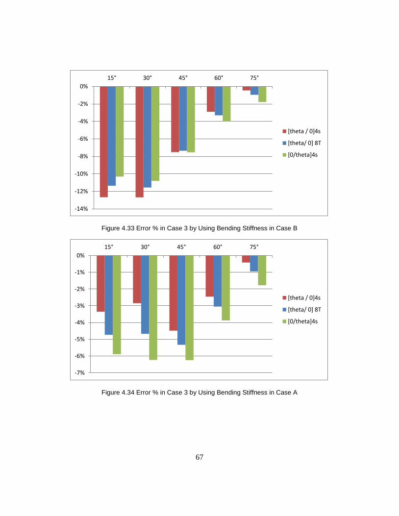
67
Figure 4.33 Error % in Case 3 by Using Bending Stiffness in Case B
Figure 4.34 Error % in Case 3 by Using Bending Stiffness in Case A
-14%
-12%
-10%
-8%
-6%
-4%
-2%
0%
15° 30° 45° 60° 75°
[theta / 0]4s
[theta/ 0] 8T
[0/theta]4s
-7%
-6%
-5%
-4%
-3%
-2%
-1%
0%
15° 30° 45° 60° 75°
[theta / 0]4s
[theta/ 0] 8T
[0/theta]4s
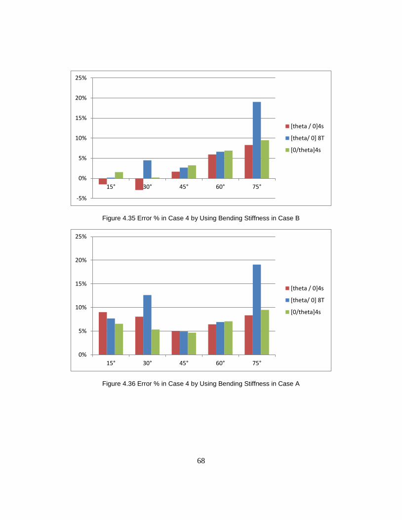
68
Figure 4.35 Error % in Case 4 by Using Bending Stiffness in Case B
Figure 4.36 Error % in Case 4 by Using Bending Stiffness in Case A
-5%
0%
5%
10%
15%
20%
25%
15° 30° 45° 60° 75°
[theta / 0]4s
[theta/ 0] 8T
[0/theta]4s
0%
5%
10%
15%
20%
25%
15° 30° 45° 60° 75°
[theta / 0]4s
[theta/ 0] 8T
[0/theta]4s
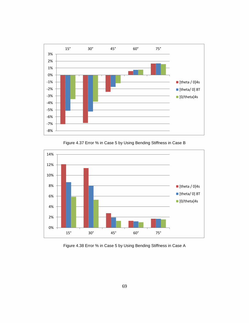
69
Figure 4.37 Error % in Case 5 by Using Bending Stiffness in Case B
Figure 4.38 Error % in Case 5 by Using Bending Stiffness in Case A
-8%
-7%
-6%
-5%
-4%
-3%
-2%
-1%
0%
1%
2%
3%
15° 30° 45° 60° 75°
[theta / 0]4s
[theta/ 0] 8T
[0/theta]4s
0%
2%
4%
6%
8%
10%
12%
14%
15° 30° 45° 60° 75°
[theta / 0]4s
[theta/ 0] 8T
[0/theta]4s
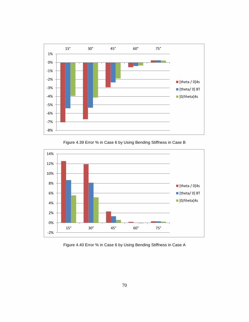
70
Figure 4.39 Error % in Case 6 by Using Bending Stiffness in Case B
Figure 4.40 Error % in Case 6 by Using Bending Stiffness in Case A
-8%
-7%
-6%
-5%
-4%
-3%
-2%
-1%
0%
1%
15° 30° 45° 60° 75°
[theta / 0]4s
[theta/ 0] 8T
[0/theta]4s
-2%
0%
2%
4%
6%
8%
10%
12%
14%
15° 30° 45° 60° 75°
[theta / 0]4s
[theta/ 0] 8T
[0/theta]4s
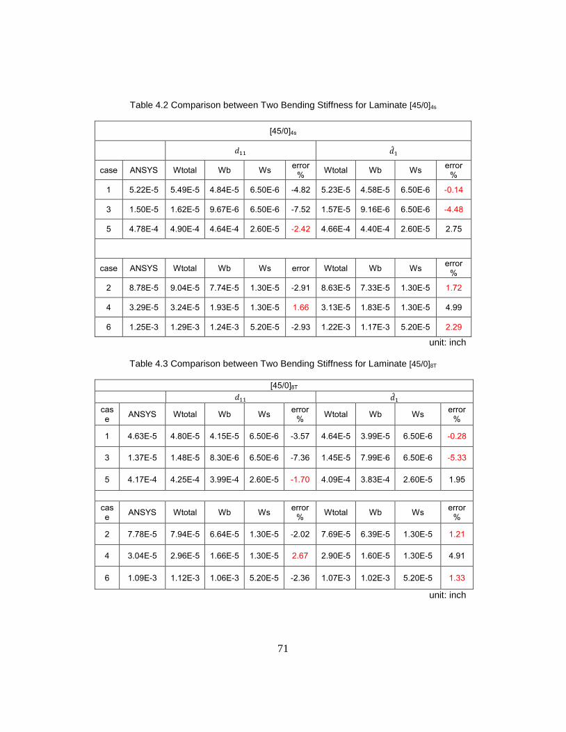
71
Table 4.2 Comparison between Two Bending Stiffness for Laminate [45/0]4s
[45/0]4s
case ANSYS Wtotal Wb Ws error
% Wtotal Wb Ws
error %
1 5.22E-5 5.49E-5 4.84E-5 6.50E-6 -4.82 5.23E-5 4.58E-5 6.50E-6 -0.14
3 1.50E-5 1.62E-5 9.67E-6 6.50E-6 -7.52 1.57E-5 9.16E-6 6.50E-6 -4.48
5 4.78E-4 4.90E-4 4.64E-4 2.60E-5 -2.42 4.66E-4 4.40E-4 2.60E-5 2.75
case ANSYS Wtotal Wb Ws error Wtotal Wb Ws error
%
2 8.78E-5 9.04E-5 7.74E-5 1.30E-5 -2.91 8.63E-5 7.33E-5 1.30E-5 1.72
4 3.29E-5 3.24E-5 1.93E-5 1.30E-5 1.66 3.13E-5 1.83E-5 1.30E-5 4.99
6 1.25E-3 1.29E-3 1.24E-3 5.20E-5 -2.93 1.22E-3 1.17E-3 5.20E-5 2.29
unit: inch
Table 4.3 Comparison between Two Bending Stiffness for Laminate [45/0]8T
[45/0]8T
case
ANSYS Wtotal Wb Ws error
% Wtotal Wb Ws
error %
1 4.63E-5 4.80E-5 4.15E-5 6.50E-6 -3.57 4.64E-5 3.99E-5 6.50E-6 -0.28
3 1.37E-5 1.48E-5 8.30E-6 6.50E-6 -7.36 1.45E-5 7.99E-6 6.50E-6 -5.33
5 4.17E-4 4.25E-4 3.99E-4 2.60E-5 -1.70 4.09E-4 3.83E-4 2.60E-5 1.95
case
ANSYS Wtotal Wb Ws error
% Wtotal Wb Ws
error %
2 7.78E-5 7.94E-5 6.64E-5 1.30E-5 -2.02 7.69E-5 6.39E-5 1.30E-5 1.21
4 3.04E-5 2.96E-5 1.66E-5 1.30E-5 2.67 2.90E-5 1.60E-5 1.30E-5 4.91
6 1.09E-3 1.12E-3 1.06E-3 5.20E-5 -2.36 1.07E-3 1.02E-3 5.20E-5 1.33
unit: inch
72
Observations:
1. takes twisting curvature into account and allow laminate twist. Once
suppressing the curvature , an extra moment will be induced. Thus, =
62
66 takes shear coupling terms into account. The bending stiffness in case A is stiffer
than case B, resulting in stiffer laminates. The stiffness increases with
suppressing . Therefore, even though some cases’ results are better by using
bending stiffness in case B, in general, case A is more acceptable.
73
Chapter 5
Conclusion
Analytical methods are developed for determining deflection of composite beams
under transverse load with various boundary conditions and laminate configurations. A
closed form expression of 1-D equivalent bending stiffness with and without presence of
twisting curvature is formulated and used for investigating the beam deflection. Finite
element analysis of 3-D ANSYS models is conducted by using Solid186 elements to
obtain the beam deflection used for comparing with analytical calculation. .
First of all, for boundary condition and loading effects, cases in concentrated load will
have larger shear deformation than cases in uniformly distributed load. Cantilever beam
cases will have larger total deflections than other cases. However, cases 3 and 4 (beam
fixed at both ends with uniformly distributed and concentrated load, respectively) have
larger shear percentage
than other cases.
Secondly, for stack sequence effects, shear deformation on beam deflection due to
stacking sequence is insignificant regardless of the type of loading. However, bending
deformations are different because equivalent bending stiffness changes with changing
stack sequences.
Thirdly, for fiber orientation effects, shear deformation increases with increasing fiber
orientations. In addition, bending deformation increases with increasing fiber orientations.
is maximum when fiber orientation is equal to 15 at which 𝜂 𝑥 𝑦 ,𝑥 reaches its
maximum value.
Lastly, using bending stiffness of the beam with induced twisting curvature (Case A)
for calculating beam deflection results in a better correlation with ANSYS results
compared with the case of bending stiffness without twisting suppression (Case B).

74
However, some beam cases, using Case B expression is fitted better than using Case A.
The future work is needed to find the shear correction factor by investigating patterns of
shear stress and experimental validation on the present analytical model.

75
Appendix A
Derived Moments for Different Boundary Conditions presented in Chapter 2
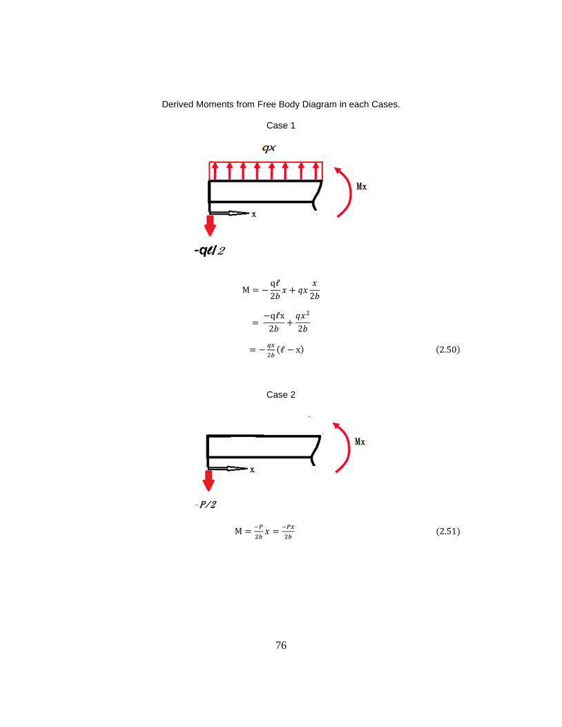
76
Derived Moments from Free Body Diagram in each Cases.
Case 1
𝑥 𝑥
𝑥
𝑥
Case 2
𝑥
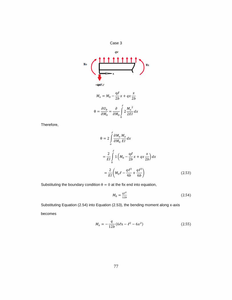
77
Case 3
𝑥 𝑥
𝑥
∫
𝐼
𝑥
Therefore,
∫
𝐼 𝑥
𝐼∫ (
𝑥 𝑥
𝑥
)
𝑥
𝐼(
)
Substituting the boundary condition at the fix end into equation,
2
Substituting Equation (2.54) into Equation (2.53), the bending moment along x-axis
becomes
𝑥
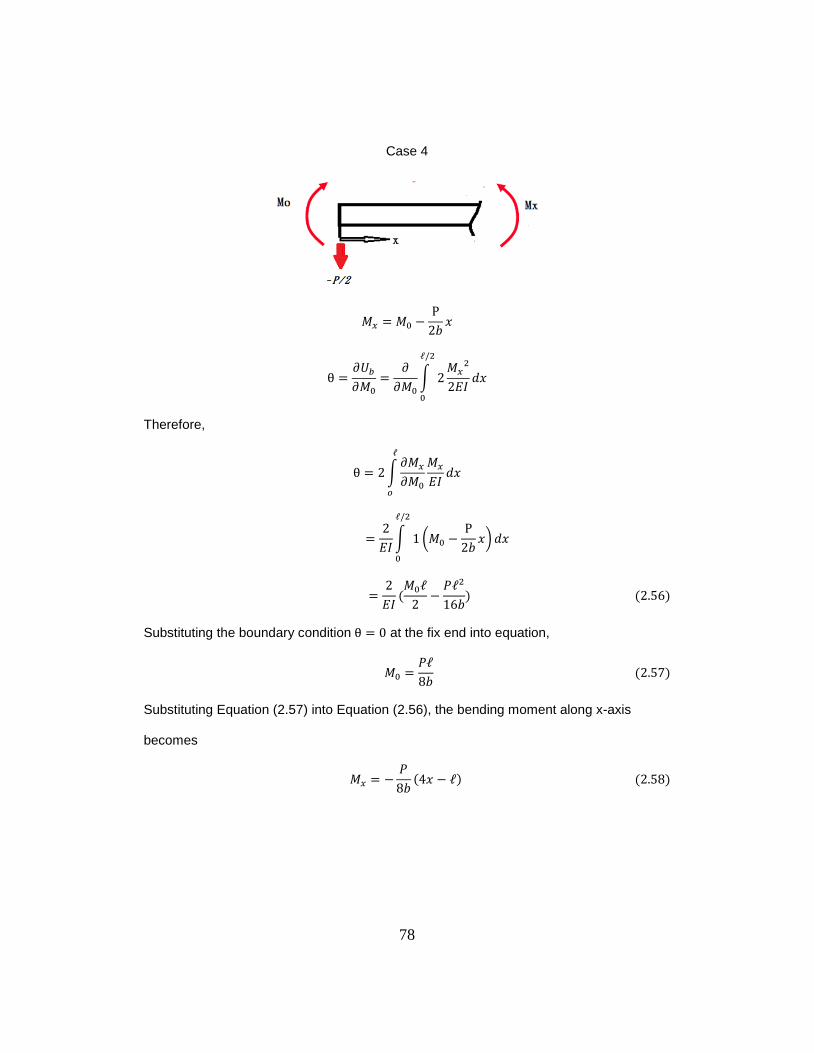
78
Case 4
𝑥
∫
𝐼
𝑥
Therefore,
∫
𝐼 𝑥
𝐼∫ (
𝑥)
𝑥
𝐼
𝑃
Substituting the boundary condition at the fix end into equation,
𝑃
Substituting Equation (2.57) into Equation (2.56), the bending moment along x-axis
becomes
𝑃
𝑥
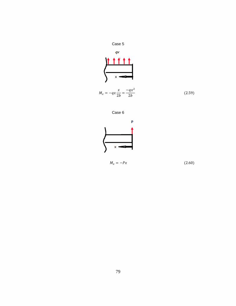
79
Case 5
𝑥𝑥
𝑥
Case 6
𝑃𝑥

80
Appendix B
Derived Beam Equations from Case 2 to Case 6
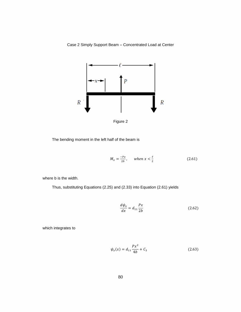
80
Case 2 Simply Support Beam – Concentrated Load at Center
Figure 2
The bending moment in the left half of the beam is
𝑥
where b is the width.
Thus, substituting Equations (2.25) and (2.33) into Equation (2.61) yields
𝑥
𝑃𝑥
which integrates to
𝑥
𝑃𝑥
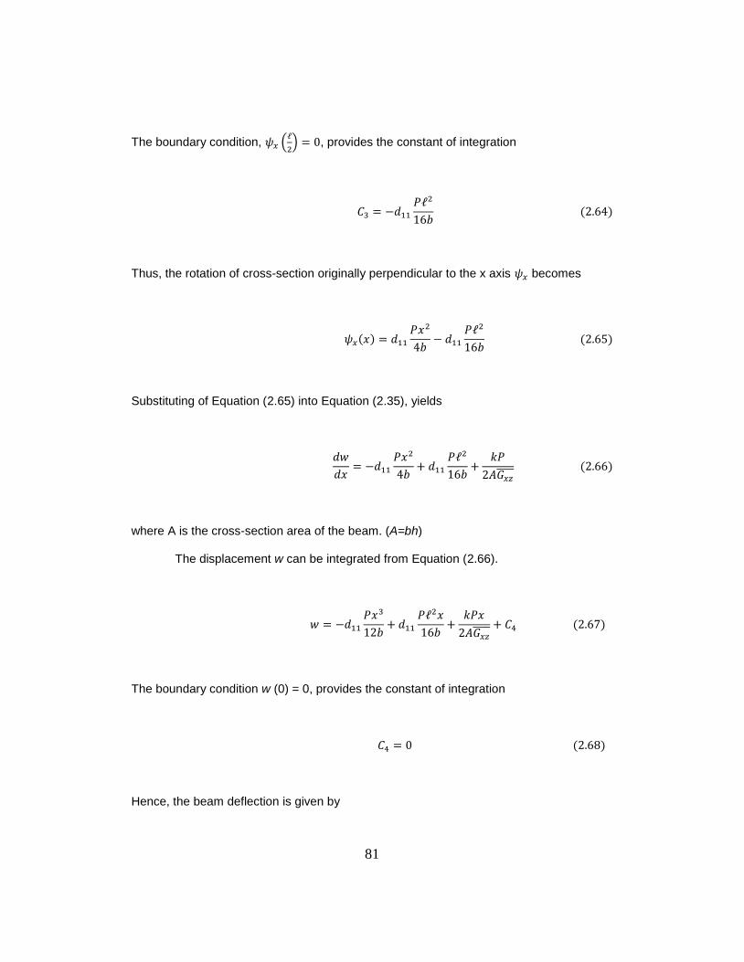
81
The boundary condition, (
) , provides the constant of integration
𝑃
Thus, the rotation of cross-section originally perpendicular to the x axis becomes
𝑥
𝑃𝑥
𝑃
Substituting of Equation (2.65) into Equation (2.35), yields
𝑥
𝑃𝑥
𝑃
𝑃
where A is the cross-section area of the beam. (A=bh)
The displacement w can be integrated from Equation (2.66).
𝑃𝑥
𝑃 𝑥
𝑃𝑥
The boundary condition w (0) = 0, provides the constant of integration
Hence, the beam deflection is given by
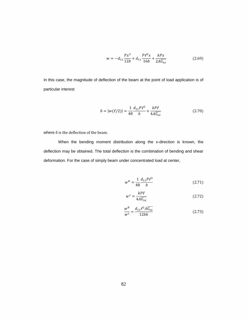
82
𝑃𝑥
𝑃 𝑥
𝑃𝑥
In this case, the magnitude of deflection of the beam at the point of load application is of
particular interest
| |
𝑃
𝑃
where
When the bending moment distribution along the x-direction is known, the
deflection may be obtained. The total deflection is the combination of bending and shear
deformation. For the case of simply beam under concentrated load at center,
𝑃
𝑃
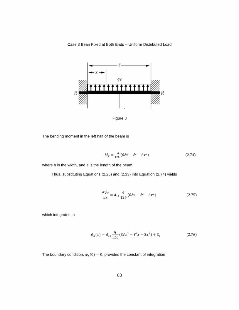
83
Case 3 Bean Fixed at Both Ends – Uniform Distributed Load
Figure 3
The bending moment in the left half of the beam is
𝑥 𝑥
where b is the width, and is the length of the beam.
Thus, substituting Equations (2.25) and (2.33) into Equation (2.74) yields
𝑥
𝑥 𝑥
which integrates to
𝑥
𝑥 𝑥 𝑥
The boundary condition, , provides the constant of integration
84
Thus, the rotation of cross-section originally perpendicular to the x axis becomes
𝑥
𝑥 𝑥 𝑥
Substituting of Equation (2.78) into Equation (2.35), yields
𝑥
𝑥 𝑥 𝑥
𝑥
where A is the cross-section area of the beam. (A=bh)
The displacement w can be integrated from Equation (2.79).
𝑥
𝑥
𝑥
𝑥 𝑥
The boundary condition w (0) = 0, provides the constant of integration
Hence, the beam deflection is given by
𝑥
𝑥
𝑥
𝑥 𝑥
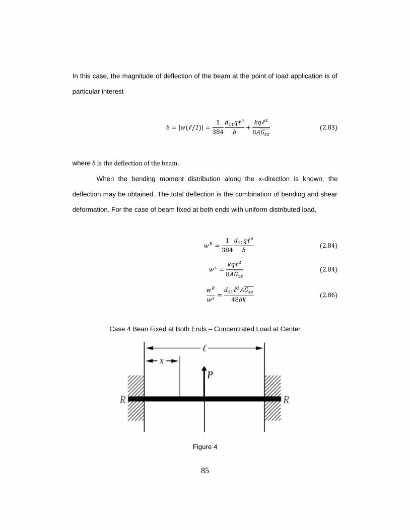
85
In this case, the magnitude of deflection of the beam at the point of load application is of
particular interest
| |
where
When the bending moment distribution along the x-direction is known, the
deflection may be obtained. The total deflection is the combination of bending and shear
deformation. For the case of beam fixed at both ends with uniform distributed load,
Case 4 Bean Fixed at Both Ends – Concentrated Load at Center
Figure 4
86
The bending moment in the left half of the beam is
𝑥
where b is the width.
Thus, substituting Equations (2.25) and (2.33) into Equation (2.87) yields
𝑥
𝑃
𝑥
which integrates to
𝑥
𝑃
𝑥 𝑥
The boundary condition, , provides the constant of integration
Thus, the rotation of cross-section originally perpendicular to the x axis becomes
𝑥
𝑃
𝑥 𝑥
Substituting of Equation (2.91) into Equation (2.35), yields
87
𝑥
𝑃
𝑥 𝑥
𝑃
where A is the cross-section area of the beam. (A=bh)
The displacement w can be integrated from Equation (2.92).
𝑃
𝑥
𝑥
𝑃𝑥
The boundary condition w (0) = 0, provides the constant of integration
Hence, the beam deflection is given by
𝑃
𝑥
𝑥
𝑃𝑥
In this case, the magnitude of deflection of the beam at the point of load application is of
particular interest
| |
𝑃
𝑃
where
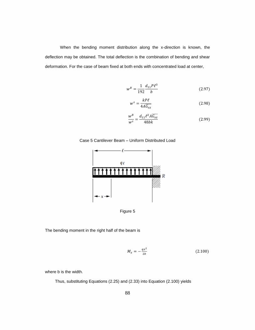
88
When the bending moment distribution along the x-direction is known, the
deflection may be obtained. The total deflection is the combination of bending and shear
deformation. For the case of beam fixed at both ends with concentrated load at center,
𝑃
𝑃
Case 5 Cantilever Beam – Uniform Distributed Load
Figure 5
The bending moment in the right half of the beam is
2
where b is the width.
Thus, substituting Equations (2.25) and (2.33) into Equation (2.100) yields
89
𝑥
𝑥
which integrates to
𝑥
𝑥
The boundary condition, , provides the constant of integration
Thus, the rotation of cross-section originally perpendicular to the x axis becomes
𝑥
𝑥
Substituting of Equation (2.104) into Equation (2.35), yields
𝑥
𝑥
𝑥
where A is the cross-section area of the beam. (A=bh)
The displacement w can be integrated from Equation (2.105).
90
𝑥
𝑥
𝑥
The boundary condition w ( ) = 0, provides the constant of integration
Hence, the beam deflection is given by
𝑥
𝑥
𝑥
In this case, the magnitude of deflection of the beam at the point of load application is of
particular interest
| |
where
When the bending moment distribution along the x-direction is known, the
deflection may be obtained. The total deflection is the combination of bending and shear
deformation. For the case of cantilever beam under uniform distributed load,
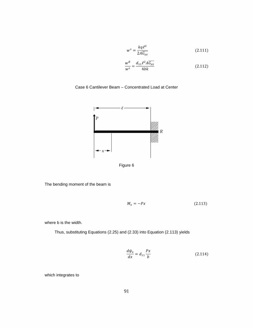
91
Case 6 Cantilever Beam – Concentrated Load at Center
Figure 6
The bending moment of the beam is
𝑃𝑥
where b is the width.
Thus, substituting Equations (2.25) and (2.33) into Equation (2.113) yields
𝑥
𝑃𝑥
which integrates to
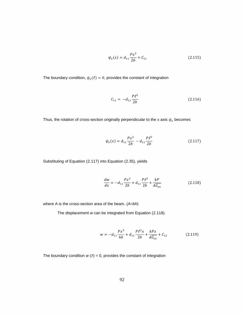
92
𝑥
𝑃𝑥
The boundary condition, , provides the constant of integration
𝑃
Thus, the rotation of cross-section originally perpendicular to the x axis becomes
𝑥
𝑃𝑥
𝑃
Substituting of Equation (2.117) into Equation (2.35), yields
𝑥
𝑃𝑥
𝑃
𝑃
where A is the cross-section area of the beam. (A=bh)
The displacement w can be integrated from Equation (2.118).
𝑃𝑥
𝑃 𝑥
𝑃𝑥
The boundary condition w ( ) = 0, provides the constant of integration
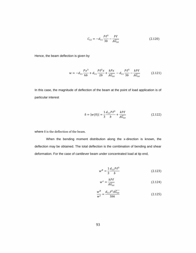
93
𝑃
𝑃
Hence, the beam deflection is given by
𝑃𝑥
𝑃 𝑥
𝑃𝑥
𝑃
𝑃
In this case, the magnitude of deflection of the beam at the point of load application is of
particular interest
| |
𝑃
𝑃
where
When the bending moment distribution along the x-direction is known, the
deflection may be obtained. The total deflection is the combination of bending and shear
deformation. For the case of cantilever beam under concentrated load at tip end,
𝑃
𝑃

94
Appendix C
Data
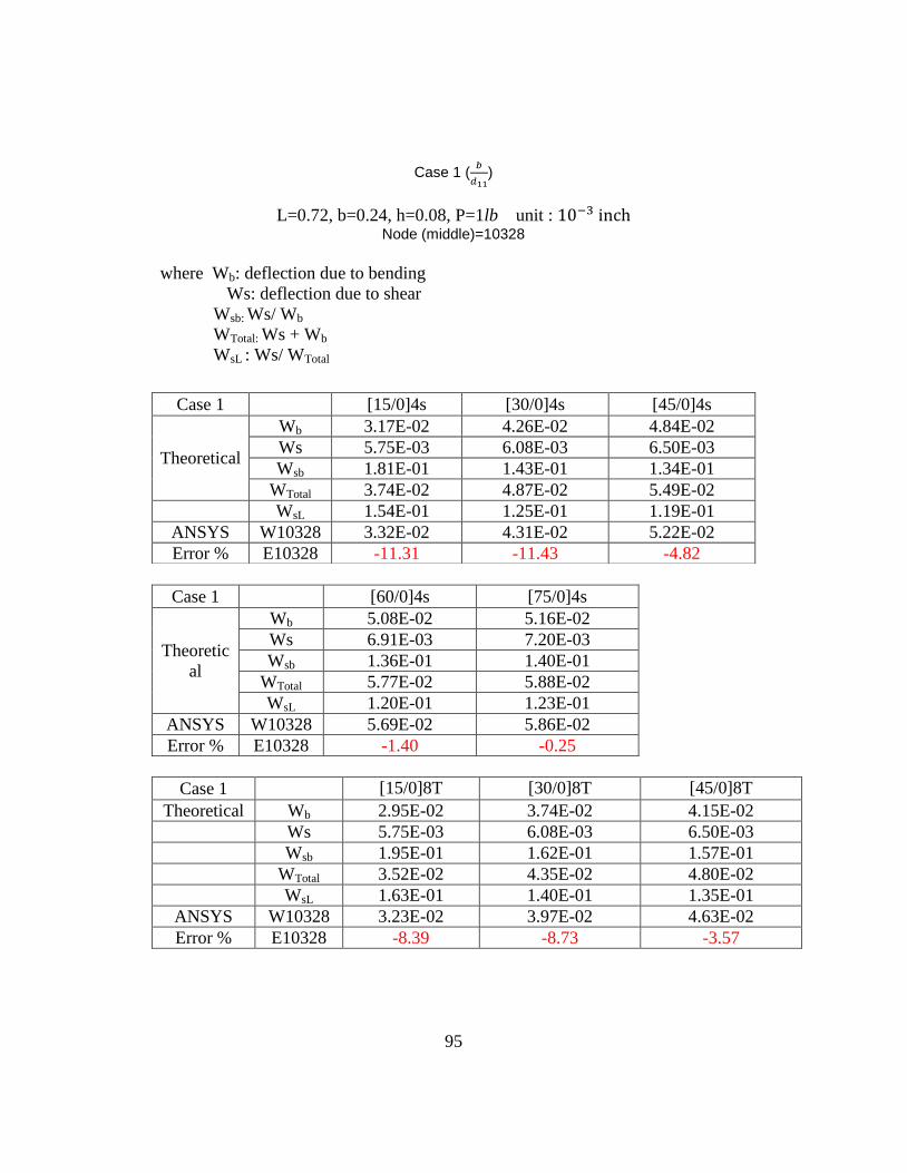
95
Case 1 (
)
L=0.72, b=0.24, h=0.08, P=1lb unit :
Node (middle)=10328
where Wb: deflection due to bending
Ws: deflection due to shear
Wsb: Ws/ Wb
WTotal: Ws + Wb
WsL : Ws/ WTotal
Case 1 [60/0]4s [75/0]4s
Theoretic
al
Wb 5.08E-02 5.16E-02
Ws 6.91E-03 7.20E-03
Wsb 1.36E-01 1.40E-01
WTotal 5.77E-02 5.88E-02
WsL 1.20E-01 1.23E-01
ANSYS W10328 5.69E-02 5.86E-02
Error % E10328 -1.40 -0.25
Case 1 [15/0]8T [30/0]8T [45/0]8T
Theoretical Wb 2.95E-02 3.74E-02 4.15E-02
Ws 5.75E-03 6.08E-03 6.50E-03
Wsb 1.95E-01 1.62E-01 1.57E-01
WTotal 3.52E-02 4.35E-02 4.80E-02
WsL 1.63E-01 1.40E-01 1.35E-01
ANSYS W10328 3.23E-02 3.97E-02 4.63E-02
Error % E10328 -8.39 -8.73 -3.57
Case 1 [15/0]4s [30/0]4s [45/0]4s
Theoretical
Wb 3.17E-02 4.26E-02 4.84E-02
Ws 5.75E-03 6.08E-03 6.50E-03
Wsb 1.81E-01 1.43E-01 1.34E-01
WTotal 3.74E-02 4.87E-02 5.49E-02
WsL 1.54E-01 1.25E-01 1.19E-01
ANSYS W10328 3.32E-02 4.31E-02 5.22E-02
Error % E10328 -11.31 -11.43 -4.82
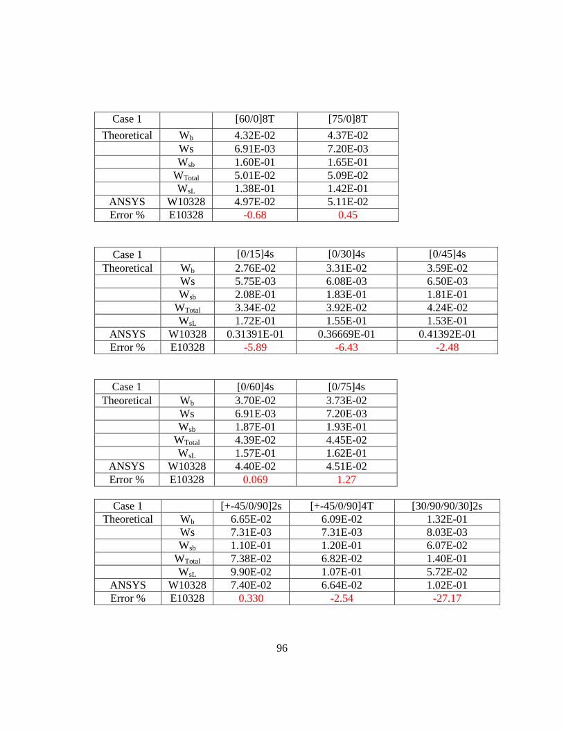
96
Case 1 [60/0]8T [75/0]8T
Theoretical Wb 4.32E-02 4.37E-02
Ws 6.91E-03 7.20E-03
Wsb 1.60E-01 1.65E-01
WTotal 5.01E-02 5.09E-02
WsL 1.38E-01 1.42E-01
ANSYS W10328 4.97E-02 5.11E-02
Error % E10328 -0.68 0.45
Case 1 [0/15]4s [0/30]4s [0/45]4s
Theoretical Wb 2.76E-02 3.31E-02 3.59E-02
Ws 5.75E-03 6.08E-03 6.50E-03
Wsb 2.08E-01 1.83E-01 1.81E-01
WTotal 3.34E-02 3.92E-02 4.24E-02
WsL 1.72E-01 1.55E-01 1.53E-01
ANSYS W10328 0.31391E-01 0.36669E-01 0.41392E-01
Error % E10328 -5.89 -6.43 -2.48
Case 1 [0/60]4s [0/75]4s
Theoretical Wb 3.70E-02 3.73E-02
Ws 6.91E-03 7.20E-03
Wsb 1.87E-01 1.93E-01
WTotal 4.39E-02 4.45E-02
WsL 1.57E-01 1.62E-01
ANSYS W10328 4.40E-02 4.51E-02
Error % E10328 0.069 1.27
Case 1 [+-45/0/90]2s [+-45/0/90]4T [30/90/90/30]2s
Theoretical Wb 6.65E-02 6.09E-02 1.32E-01
Ws 7.31E-03 7.31E-03 8.03E-03
Wsb 1.10E-01 1.20E-01 6.07E-02
WTotal 7.38E-02 6.82E-02 1.40E-01
WsL 9.90E-02 1.07E-01 5.72E-02
ANSYS W10328 7.40E-02 6.64E-02 1.02E-01
Error % E10328 0.330 -2.54 -27.17
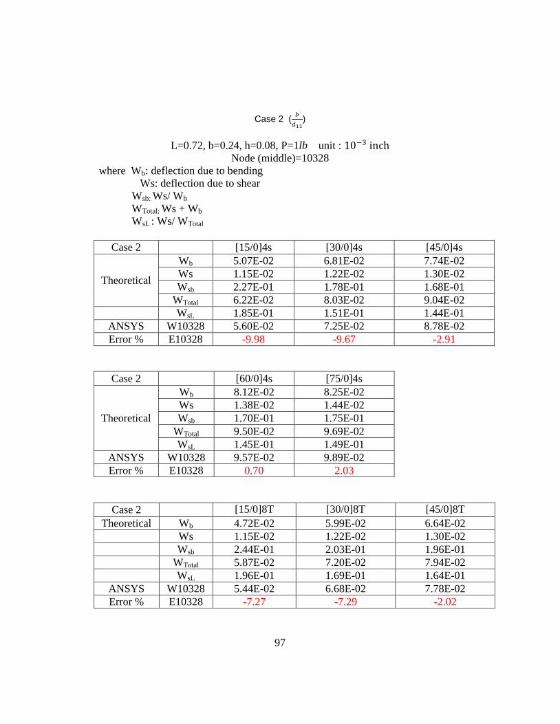
97
Case 2 (
)
L=0.72, b=0.24, h=0.08, P=1lb unit :
Node (middle)=10328
where Wb: deflection due to bending
Ws: deflection due to shear
Wsb: Ws/ Wb
WTotal: Ws + Wb
WsL : Ws/ WTotal
Case 2 [15/0]4s [30/0]4s [45/0]4s
Theoretical
Wb 5.07E-02 6.81E-02 7.74E-02
Ws 1.15E-02 1.22E-02 1.30E-02
Wsb 2.27E-01 1.78E-01 1.68E-01
WTotal 6.22E-02 8.03E-02 9.04E-02
WsL 1.85E-01 1.51E-01 1.44E-01
ANSYS W10328 5.60E-02 7.25E-02 8.78E-02
Error % E10328 -9.98 -9.67 -2.91
Case 2 [60/0]4s [75/0]4s
Theoretical
Wb 8.12E-02 8.25E-02
Ws 1.38E-02 1.44E-02
Wsb 1.70E-01 1.75E-01
WTotal 9.50E-02 9.69E-02
WsL 1.45E-01 1.49E-01
ANSYS W10328 9.57E-02 9.89E-02
Error % E10328 0.70 2.03
Case 2 [15/0]8T [30/0]8T [45/0]8T
Theoretical Wb 4.72E-02 5.99E-02 6.64E-02
Ws 1.15E-02 1.22E-02 1.30E-02
Wsb 2.44E-01 2.03E-01 1.96E-01
WTotal 5.87E-02 7.20E-02 7.94E-02
WsL 1.96E-01 1.69E-01 1.64E-01
ANSYS W10328 5.44E-02 6.68E-02 7.78E-02
Error % E10328 -7.27 -7.29 -2.02
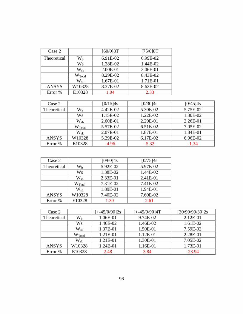
98
Case 2 [60/0]8T [75/0]8T
Theoretical Wb 6.91E-02 6.99E-02
Ws 1.38E-02 1.44E-02
Wsb 2.00E-01 2.06E-01
WTotal 8.29E-02 8.43E-02
WsL 1.67E-01 1.71E-01
ANSYS W10328 8.37E-02 8.62E-02
Error % E10328 1.04 2.33
Case 2 [0/15]4s [0/30]4s [0/45]4s
Theoretical Wb 4.42E-02 5.30E-02 5.75E-02
Ws 1.15E-02 1.22E-02 1.30E-02
Wsb 2.60E-01 2.29E-01 2.26E-01
WTotal 5.57E-02 6.51E-02 7.05E-02
WsL 2.07E-01 1.87E-01 1.84E-01
ANSYS W10328 5.29E-02 6.17E-02 6.96E-02
Error % E10328 -4.96 -5.32 -1.34
Case 2 [0/60]4s [0/75]4s
Theoretical Wb 5.92E-02 5.97E-02
Ws 1.38E-02 1.44E-02
Wsb 2.33E-01 2.41E-01
WTotal 7.31E-02 7.41E-02
WsL 1.89E-01 1.94E-01
ANSYS W10328 7.40E-02 7.60E-02
Error % E10328 1.30 2.61
Case 2 [+-45/0/90]2s [+-45/0/90]4T [30/90/90/30]2s
Theoretical Wb 1.06E-01 9.74E-02 2.12E-01
Ws 1.46E-02 1.46E-02 1.61E-02
Wsb 1.37E-01 1.50E-01 7.59E-02
WTotal 1.21E-01 1.12E-01 2.28E-01
WsL 1.21E-01 1.30E-01 7.05E-02
ANSYS W10328 1.24E-01 1.16E-01 1.73E-01
Error % E10328 2.48 3.84 -23.94
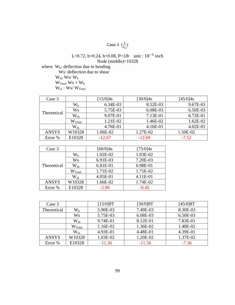
99
Case 3 (
)
L=0.72, b=0.24, h=0.08, P=1lb unit :
Node (middle)=10328
where Wb: deflection due to bending
Ws: deflection due to shear
Wsb: Ws/ Wb
WTotal: Ws + Wb
WsL : Ws/ WTotal
Case 3 [15/0]4s [30/0]4s [45/0]4s
Theoretical
Wb 6.34E-03 8.52E-03 9.67E-03
Ws 5.75E-03 6.08E-03 6.50E-03
Wsb 9.07E-01 7.13E-01 6.72E-01
WTotal 1.21E-02 1.46E-02 1.62E-02
WsL 4.76E-01 4.16E-01 4.02E-01
ANSYS W10328 1.06E-02 1.27E-02 1.50E-02
Error % E10328 -12.67 -12.69 -7.52
Case 3 [60/0]4s [75/0]4s
Theoretical
Wb 1.02E-02 1.03E-02
Ws 6.91E-03 7.20E-03
Wsb 6.81E-01 6.98E-01
WTotal 1.71E-02 1.75E-02
WsL 4.05E-01 4.11E-01
ANSYS W10328 1.66E-02 1.74E-02
Error % E10328 -2.90 -0.45
Case 3 [15/0]8T [30/0]8T [45/0]8T
Theoretical Wb 5.90E-03 7.49E-03 8.30E-03
Ws 5.75E-03 6.08E-03 6.50E-03
Wsb 9.74E-01 8.12E-01 7.83E-01
WTotal 1.16E-02 1.36E-02 1.48E-02
WsL 4.93E-01 4.48E-01 4.39E-01
ANSYS W10328 1.03E-02 1.20E-02 1.37E-02
Error % E10328 -11.36 -11.56 -7.36
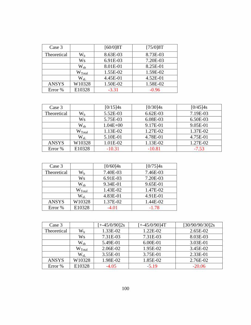
100
Case 3 [60/0]8T [75/0]8T
Theoretical Wb 8.63E-03 8.73E-03
Ws 6.91E-03 7.20E-03
Wsb 8.01E-01 8.25E-01
WTotal 1.55E-02 1.59E-02
WsL 4.45E-01 4.52E-01
ANSYS W10328 1.50E-02 1.58E-02
Error % E10328 -3.31 -0.96
Case 3 [0/15]4s [0/30]4s [0/45]4s
Theoretical Wb 5.52E-03 6.62E-03 7.19E-03
Ws 5.75E-03 6.08E-03 6.50E-03
Wsb 1.04E+00 9.17E-01 9.05E-01
WTotal 1.13E-02 1.27E-02 1.37E-02
WsL 5.10E-01 4.78E-01 4.75E-01
ANSYS W10328 1.01E-02 1.13E-02 1.27E-02
Error % E10328 -10.31 -10.81 -7.53
Case 3 [0/60]4s [0/75]4s
Theoretical Wb 7.40E-03 7.46E-03
Ws 6.91E-03 7.20E-03
Wsb 9.34E-01 9.65E-01
WTotal 1.43E-02 1.47E-02
WsL 4.83E-01 4.91E-01
ANSYS W10328 1.37E-02 1.44E-02
Error % E10328 -4.01 -1.78
Case 3 [+-45/0/90]2s [+-45/0/90]4T [30/90/90/30]2s
Theoretical Wb 1.33E-02 1.22E-02 2.65E-02
Ws 7.31E-03 7.31E-03 8.03E-03
Wsb 5.49E-01 6.00E-01 3.03E-01
WTotal 2.06E-02 1.95E-02 3.45E-02
WsL 3.55E-01 3.75E-01 2.33E-01
ANSYS W10328 1.98E-02 1.85E-02 2.76E-02
Error % E10328 -4.05 -5.19 -20.06
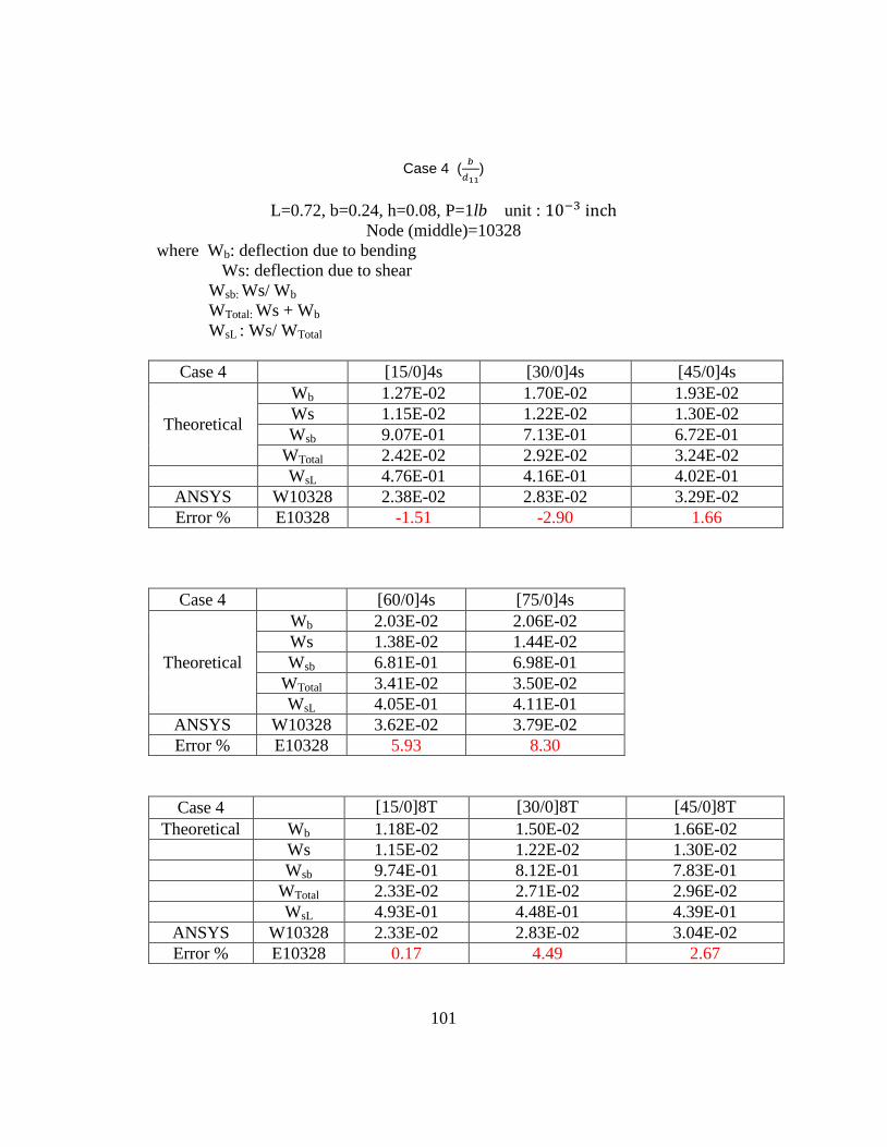
101
Case 4 (
)
L=0.72, b=0.24, h=0.08, P=1lb unit :
Node (middle)=10328
where Wb: deflection due to bending
Ws: deflection due to shear
Wsb: Ws/ Wb
WTotal: Ws + Wb
WsL : Ws/ WTotal
Case 4 [15/0]4s [30/0]4s [45/0]4s
Theoretical
Wb 1.27E-02 1.70E-02 1.93E-02
Ws 1.15E-02 1.22E-02 1.30E-02
Wsb 9.07E-01 7.13E-01 6.72E-01
WTotal 2.42E-02 2.92E-02 3.24E-02
WsL 4.76E-01 4.16E-01 4.02E-01
ANSYS W10328 2.38E-02 2.83E-02 3.29E-02
Error % E10328 -1.51 -2.90 1.66
Case 4 [60/0]4s [75/0]4s
Theoretical
Wb 2.03E-02 2.06E-02
Ws 1.38E-02 1.44E-02
Wsb 6.81E-01 6.98E-01
WTotal 3.41E-02 3.50E-02
WsL 4.05E-01 4.11E-01
ANSYS W10328 3.62E-02 3.79E-02
Error % E10328 5.93 8.30
Case 4 [15/0]8T [30/0]8T [45/0]8T
Theoretical Wb 1.18E-02 1.50E-02 1.66E-02
Ws 1.15E-02 1.22E-02 1.30E-02
Wsb 9.74E-01 8.12E-01 7.83E-01
WTotal 2.33E-02 2.71E-02 2.96E-02
WsL 4.93E-01 4.48E-01 4.39E-01
ANSYS W10328 2.33E-02 2.83E-02 3.04E-02
Error % E10328 0.17 4.49 2.67
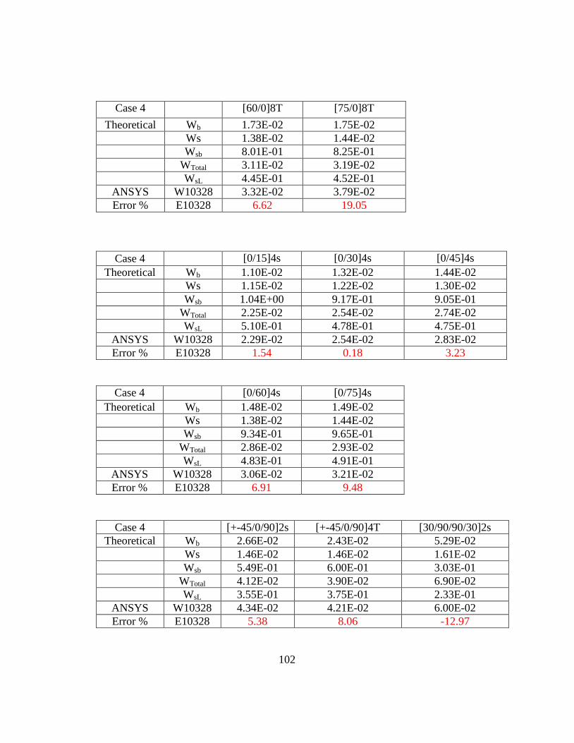
102
Case 4 [60/0]8T [75/0]8T
Theoretical Wb 1.73E-02 1.75E-02
Ws 1.38E-02 1.44E-02
Wsb 8.01E-01 8.25E-01
WTotal 3.11E-02 3.19E-02
WsL 4.45E-01 4.52E-01
ANSYS W10328 3.32E-02 3.79E-02
Error % E10328 6.62 19.05
Case 4 [0/15]4s [0/30]4s [0/45]4s
Theoretical Wb 1.10E-02 1.32E-02 1.44E-02
Ws 1.15E-02 1.22E-02 1.30E-02
Wsb 1.04E+00 9.17E-01 9.05E-01
WTotal 2.25E-02 2.54E-02 2.74E-02
WsL 5.10E-01 4.78E-01 4.75E-01
ANSYS W10328 2.29E-02 2.54E-02 2.83E-02
Error % E10328 1.54 0.18 3.23
Case 4 [0/60]4s [0/75]4s
Theoretical Wb 1.48E-02 1.49E-02
Ws 1.38E-02 1.44E-02
Wsb 9.34E-01 9.65E-01
WTotal 2.86E-02 2.93E-02
WsL 4.83E-01 4.91E-01
ANSYS W10328 3.06E-02 3.21E-02
Error % E10328 6.91 9.48
Case 4 [+-45/0/90]2s [+-45/0/90]4T [30/90/90/30]2s
Theoretical Wb 2.66E-02 2.43E-02 5.29E-02
Ws 1.46E-02 1.46E-02 1.61E-02
Wsb 5.49E-01 6.00E-01 3.03E-01
WTotal 4.12E-02 3.90E-02 6.90E-02
WsL 3.55E-01 3.75E-01 2.33E-01
ANSYS W10328 4.34E-02 4.21E-02 6.00E-02
Error % E10328 5.38 8.06 -12.97
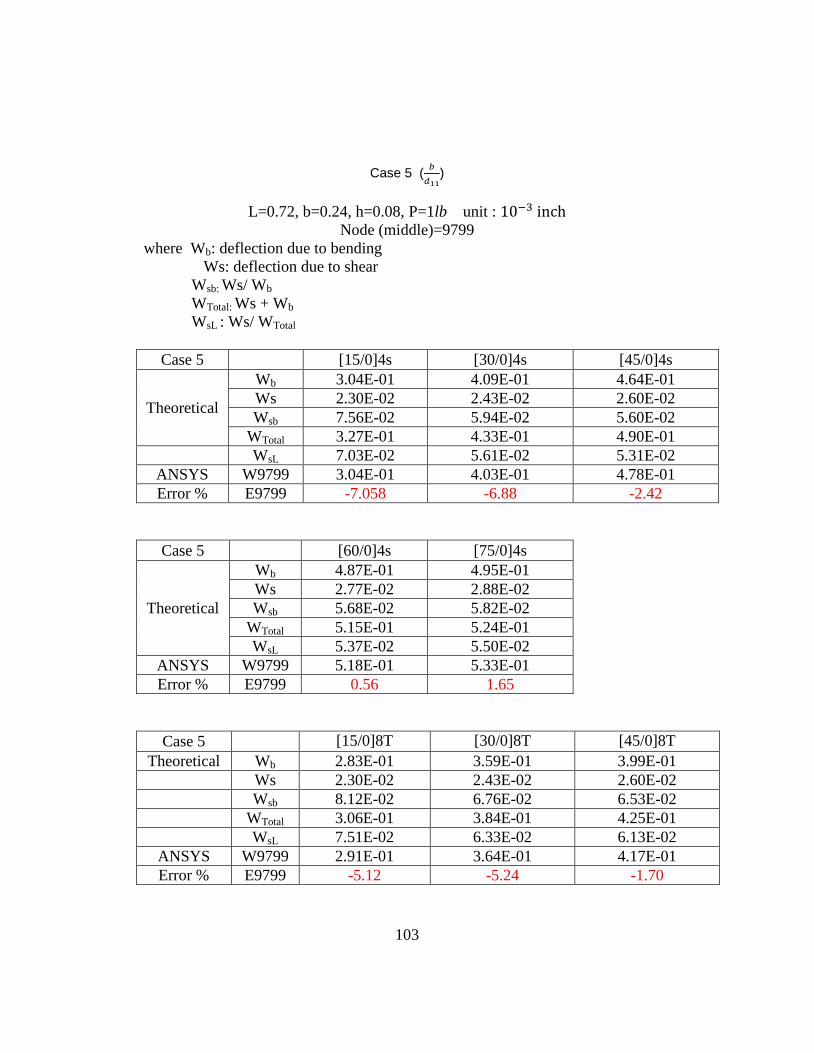
103
Case 5 (
)
L=0.72, b=0.24, h=0.08, P=1lb unit :
Node (middle)=9799
where Wb: deflection due to bending
Ws: deflection due to shear
Wsb: Ws/ Wb
WTotal: Ws + Wb
WsL : Ws/ WTotal
Case 5 [15/0]4s [30/0]4s [45/0]4s
Theoretical
Wb 3.04E-01 4.09E-01 4.64E-01
Ws 2.30E-02 2.43E-02 2.60E-02
Wsb 7.56E-02 5.94E-02 5.60E-02
WTotal 3.27E-01 4.33E-01 4.90E-01
WsL 7.03E-02 5.61E-02 5.31E-02
ANSYS W9799 3.04E-01 4.03E-01 4.78E-01
Error % E9799 -7.058 -6.88 -2.42
Case 5 [60/0]4s [75/0]4s
Theoretical
Wb 4.87E-01 4.95E-01
Ws 2.77E-02 2.88E-02
Wsb 5.68E-02 5.82E-02
WTotal 5.15E-01 5.24E-01
WsL 5.37E-02 5.50E-02
ANSYS W9799 5.18E-01 5.33E-01
Error % E9799 0.56 1.65
Case 5 [15/0]8T [30/0]8T [45/0]8T
Theoretical Wb 2.83E-01 3.59E-01 3.99E-01
Ws 2.30E-02 2.43E-02 2.60E-02
Wsb 8.12E-02 6.76E-02 6.53E-02
WTotal 3.06E-01 3.84E-01 4.25E-01
WsL 7.51E-02 6.33E-02 6.13E-02
ANSYS W9799 2.91E-01 3.64E-01 4.17E-01
Error % E9799 -5.12 -5.24 -1.70
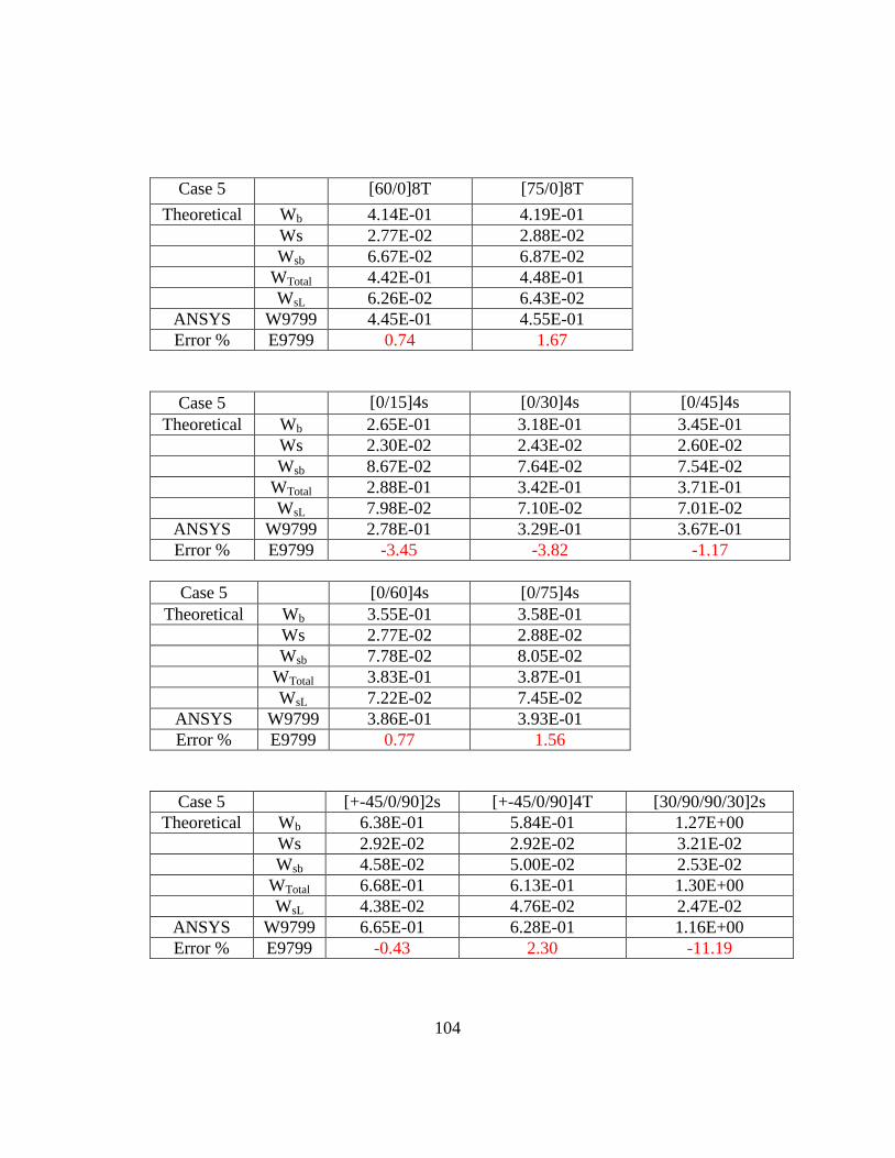
104
Case 5 [60/0]8T [75/0]8T
Theoretical Wb 4.14E-01 4.19E-01
Ws 2.77E-02 2.88E-02
Wsb 6.67E-02 6.87E-02
WTotal 4.42E-01 4.48E-01
WsL 6.26E-02 6.43E-02
ANSYS W9799 4.45E-01 4.55E-01
Error % E9799 0.74 1.67
Case 5 [0/15]4s [0/30]4s [0/45]4s
Theoretical Wb 2.65E-01 3.18E-01 3.45E-01
Ws 2.30E-02 2.43E-02 2.60E-02
Wsb 8.67E-02 7.64E-02 7.54E-02
WTotal 2.88E-01 3.42E-01 3.71E-01
WsL 7.98E-02 7.10E-02 7.01E-02
ANSYS W9799 2.78E-01 3.29E-01 3.67E-01
Error % E9799 -3.45 -3.82 -1.17
Case 5 [0/60]4s [0/75]4s
Theoretical Wb 3.55E-01 3.58E-01
Ws 2.77E-02 2.88E-02
Wsb 7.78E-02 8.05E-02
WTotal 3.83E-01 3.87E-01
WsL 7.22E-02 7.45E-02
ANSYS W9799 3.86E-01 3.93E-01
Error % E9799 0.77 1.56
Case 5 [+-45/0/90]2s [+-45/0/90]4T [30/90/90/30]2s
Theoretical Wb 6.38E-01 5.84E-01 1.27E+00
Ws 2.92E-02 2.92E-02 3.21E-02
Wsb 4.58E-02 5.00E-02 2.53E-02
WTotal 6.68E-01 6.13E-01 1.30E+00
WsL 4.38E-02 4.76E-02 2.47E-02
ANSYS W9799 6.65E-01 6.28E-01 1.16E+00
Error % E9799 -0.43 2.30 -11.19
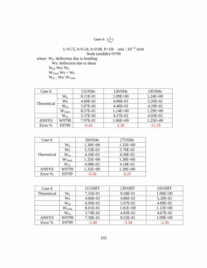
105
Case 6 (
)
L=0.72, b=0.24, h=0.08, P=1lb unit :
Node (middle)=9799
where Wb: deflection due to bending
Ws: deflection due to shear
Wsb: Ws/ Wb
WTotal: Ws + Wb
WsL : Ws/ WTotal
Case 6 [60/0]4s [75/0]4s
Theoretical
Wb 1.30E+00 1.32E+00
Ws 5.53E-02 5.76E-02
Wsb 4.26E-02 4.36E-02
WTotal 1.35E+00 1.38E+00
WsL 4.08E-02 4.18E-02
ANSYS W9799 1.35E+00 1.38E+00
Error % E9799 -0.56 0.25
Case 6 [15/0]8T [30/0]8T [45/0]8T
Theoretical Wb 7.55E-01 9.58E-01 1.06E+00
Ws 4.60E-02 4.86E-02 5.20E-02
Wsb 6.09E-02 5.07E-02 4.89E-02
WTotal 8.01E-01 1.01E+00 1.12E+00
WsL 5.74E-02 4.83E-02 4.67E-02
ANSYS W9799 7.58E-01 9.53E-01 1.09E+00
Error % E9799 -5.40 -5.34 -2.36
Case 6 [15/0]4s [30/0]4s [45/0]4s
Theoretical
Wb 8.11E-01 1.09E+00 1.24E+00
Ws 4.60E-02 4.86E-02 5.20E-02
Wsb 5.67E-02 4.46E-02 4.20E-02
WTotal 8.57E-01 1.14E+00 1.29E+00
WsL 5.37E-02 4.27E-02 4.03E-02
ANSYS W9799 7.97E-01 1.06E+00 1.25E+00
Error % E9799 -0.43 2.30 -11.19
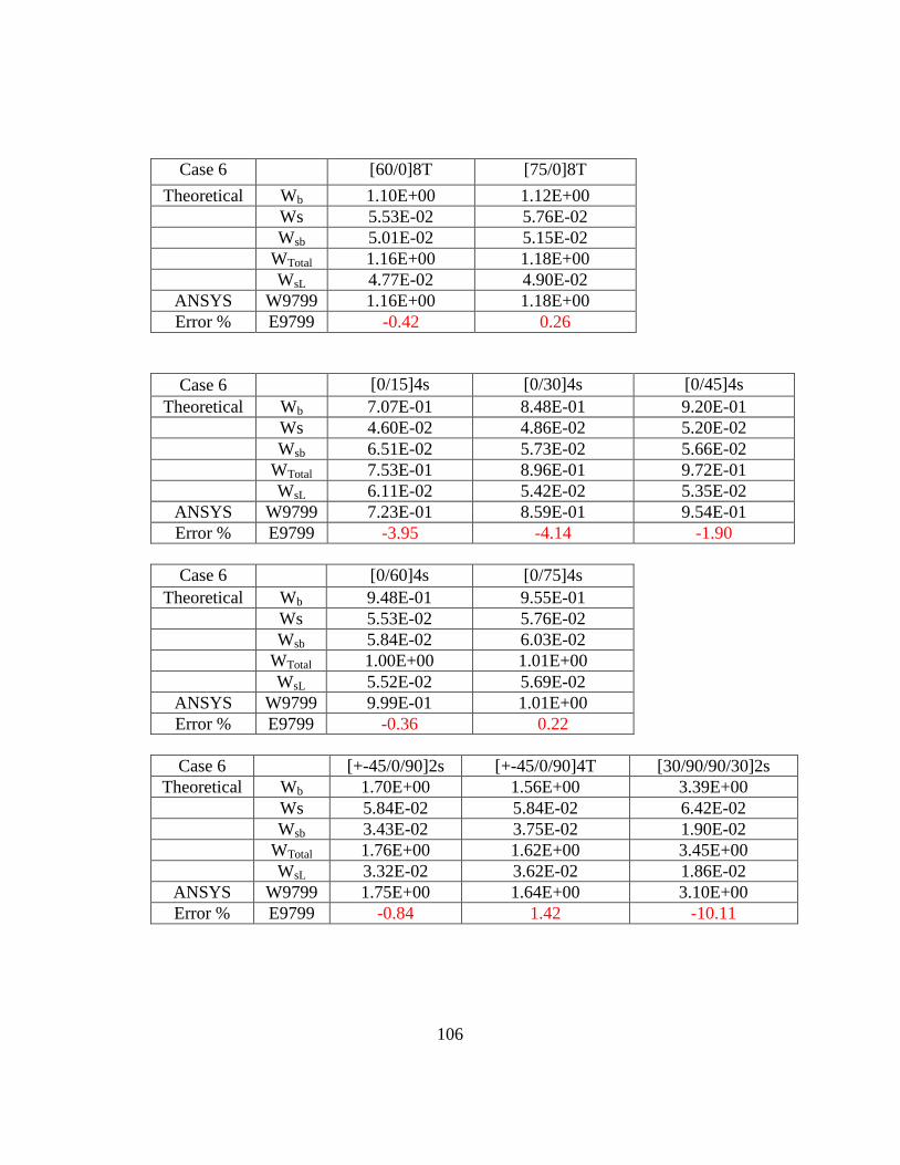
106
Case 6 [60/0]8T [75/0]8T
Theoretical Wb 1.10E+00 1.12E+00
Ws 5.53E-02 5.76E-02
Wsb 5.01E-02 5.15E-02
WTotal 1.16E+00 1.18E+00
WsL 4.77E-02 4.90E-02
ANSYS W9799 1.16E+00 1.18E+00
Error % E9799 -0.42 0.26
Case 6 [0/15]4s [0/30]4s [0/45]4s
Theoretical Wb 7.07E-01 8.48E-01 9.20E-01
Ws 4.60E-02 4.86E-02 5.20E-02
Wsb 6.51E-02 5.73E-02 5.66E-02
WTotal 7.53E-01 8.96E-01 9.72E-01
WsL 6.11E-02 5.42E-02 5.35E-02
ANSYS W9799 7.23E-01 8.59E-01 9.54E-01
Error % E9799 -3.95 -4.14 -1.90
Case 6 [0/60]4s [0/75]4s
Theoretical Wb 9.48E-01 9.55E-01
Ws 5.53E-02 5.76E-02
Wsb 5.84E-02 6.03E-02
WTotal 1.00E+00 1.01E+00
WsL 5.52E-02 5.69E-02
ANSYS W9799 9.99E-01 1.01E+00
Error % E9799 -0.36 0.22
Case 6 [+-45/0/90]2s [+-45/0/90]4T [30/90/90/30]2s
Theoretical Wb 1.70E+00 1.56E+00 3.39E+00
Ws 5.84E-02 5.84E-02 6.42E-02
Wsb 3.43E-02 3.75E-02 1.90E-02
WTotal 1.76E+00 1.62E+00 3.45E+00
WsL 3.32E-02 3.62E-02 1.86E-02
ANSYS W9799 1.75E+00 1.64E+00 3.10E+00
Error % E9799 -0.84 1.42 -10.11
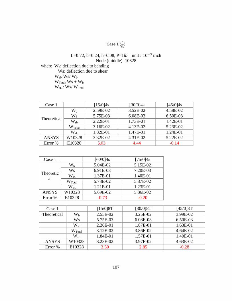
107
Case 1 (
)
L=0.72, b=0.24, h=0.08, P=1lb unit :
Node (middle)=10328
where Wb: deflection due to bending
Ws: deflection due to shear
Wsb: Ws/ Wb
WTotal: Ws + Wb
WsL : Ws/ WTotal
Case 1 [60/0]4s [75/0]4s
Theoretic
al
Wb 5.04E-02 5.15E-02
Ws 6.91E-03 7.20E-03
Wsb 1.37E-01 1.40E-01
WTotal 5.73E-02 5.87E-02
WsL 1.21E-01 1.23E-01
ANSYS W10328 5.69E-02 5.86E-02
Error % E10328 -0.73 -0.20
Case 1 [15/0]8T [30/0]8T [45/0]8T
Theoretical Wb 2.55E-02 3.25E-02 3.99E-02
Ws 5.75E-03 6.08E-03 6.50E-03
Wsb 2.26E-01 1.87E-01 1.63E-01
WTotal 3.12E-02 3.86E-02 4.64E-02
WsL 1.84E-01 1.57E-01 1.40E-01
ANSYS W10328 3.23E-02 3.97E-02 4.63E-02
Error % E10328 3.50 2.85 -0.28
Case 1 [15/0]4s [30/0]4s [45/0]4s
Theoretical
Wb 2.59E-02 3.52E-02 4.58E-02
Ws 5.75E-03 6.08E-03 6.50E-03
Wsb 2.22E-01 1.73E-01 1.42E-01
WTotal 3.16E-02 4.13E-02 5.23E-02
WsL 1.82E-01 1.47E-01 1.24E-01
ANSYS W10328 3.32E-02 4.31E-02 5.22E-02
Error % E10328 5.03 4.44 -0.14
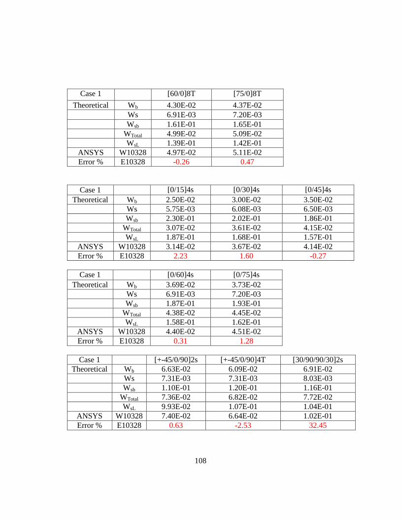
108
Case 1 [60/0]8T [75/0]8T
Theoretical Wb 4.30E-02 4.37E-02
Ws 6.91E-03 7.20E-03
Wsb 1.61E-01 1.65E-01
WTotal 4.99E-02 5.09E-02
WsL 1.39E-01 1.42E-01
ANSYS W10328 4.97E-02 5.11E-02
Error % E10328 -0.26 0.47
Case 1 [0/15]4s [0/30]4s [0/45]4s
Theoretical Wb 2.50E-02 3.00E-02 3.50E-02
Ws 5.75E-03 6.08E-03 6.50E-03
Wsb 2.30E-01 2.02E-01 1.86E-01
WTotal 3.07E-02 3.61E-02 4.15E-02
WsL 1.87E-01 1.68E-01 1.57E-01
ANSYS W10328 3.14E-02 3.67E-02 4.14E-02
Error % E10328 2.23 1.60 -0.27
Case 1 [0/60]4s [0/75]4s
Theoretical Wb 3.69E-02 3.73E-02
Ws 6.91E-03 7.20E-03
Wsb 1.87E-01 1.93E-01
WTotal 4.38E-02 4.45E-02
WsL 1.58E-01 1.62E-01
ANSYS W10328 4.40E-02 4.51E-02
Error % E10328 0.31 1.28
Case 1 [+-45/0/90]2s [+-45/0/90]4T [30/90/90/30]2s
Theoretical Wb 6.63E-02 6.09E-02 6.91E-02
Ws 7.31E-03 7.31E-03 8.03E-03
Wsb 1.10E-01 1.20E-01 1.16E-01
WTotal 7.36E-02 6.82E-02 7.72E-02
WsL 9.93E-02 1.07E-01 1.04E-01
ANSYS W10328 7.40E-02 6.64E-02 1.02E-01
Error % E10328 0.63 -2.53 32.45
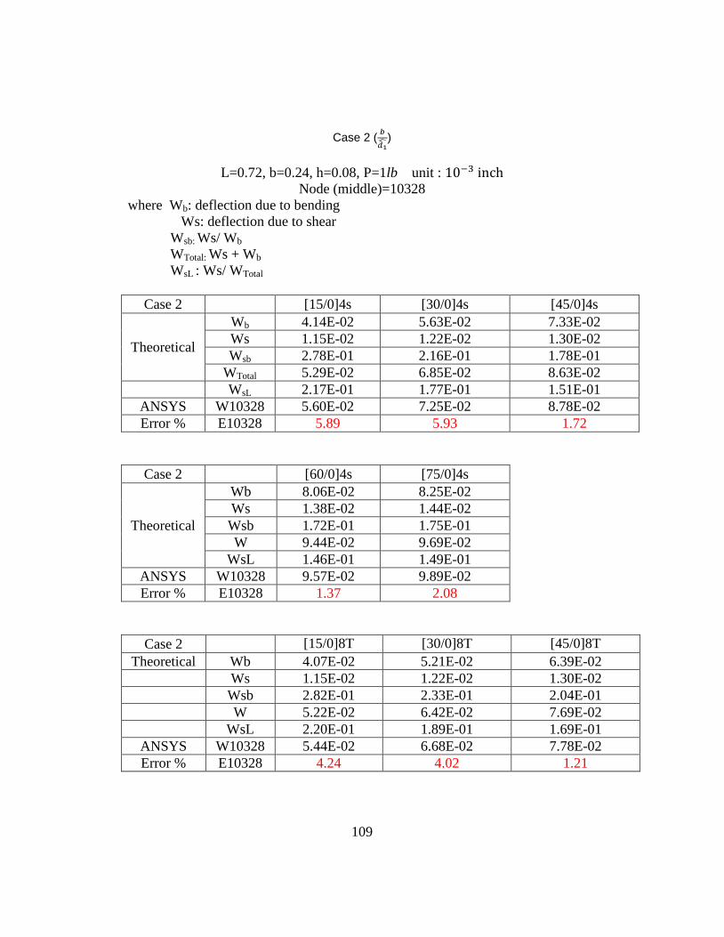
109
Case 2 (
)
L=0.72, b=0.24, h=0.08, P=1lb unit :
Node (middle)=10328
where Wb: deflection due to bending
Ws: deflection due to shear
Wsb: Ws/ Wb
WTotal: Ws + Wb
WsL : Ws/ WTotal
Case 2 [15/0]4s [30/0]4s [45/0]4s
Theoretical
Wb 4.14E-02 5.63E-02 7.33E-02
Ws 1.15E-02 1.22E-02 1.30E-02
Wsb 2.78E-01 2.16E-01 1.78E-01
WTotal 5.29E-02 6.85E-02 8.63E-02
WsL 2.17E-01 1.77E-01 1.51E-01
ANSYS W10328 5.60E-02 7.25E-02 8.78E-02
Error % E10328 5.89 5.93 1.72
Case 2 [60/0]4s [75/0]4s
Theoretical
Wb 8.06E-02 8.25E-02
Ws 1.38E-02 1.44E-02
Wsb 1.72E-01 1.75E-01
W 9.44E-02 9.69E-02
WsL 1.46E-01 1.49E-01
ANSYS W10328 9.57E-02 9.89E-02
Error % E10328 1.37 2.08
Case 2 [15/0]8T [30/0]8T [45/0]8T
Theoretical Wb 4.07E-02 5.21E-02 6.39E-02
Ws 1.15E-02 1.22E-02 1.30E-02
Wsb 2.82E-01 2.33E-01 2.04E-01
W 5.22E-02 6.42E-02 7.69E-02
WsL 2.20E-01 1.89E-01 1.69E-01
ANSYS W10328 5.44E-02 6.68E-02 7.78E-02
Error % E10328 4.24 4.02 1.21
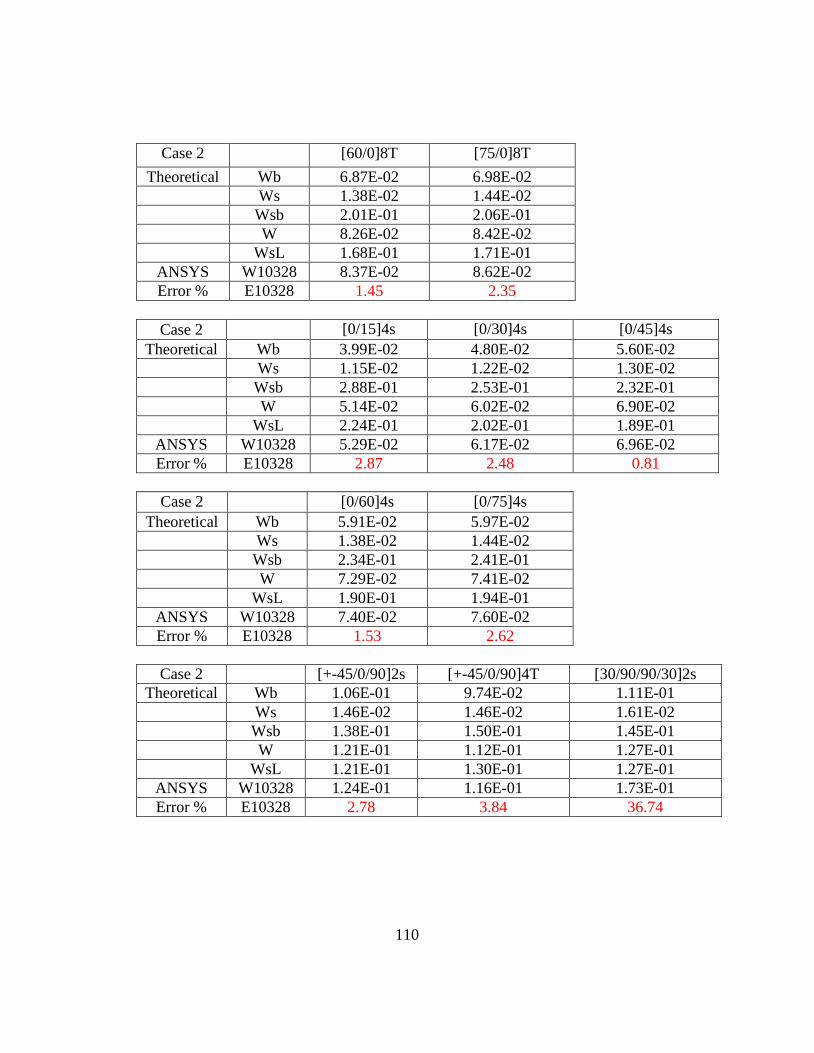
110
Case 2 [60/0]8T [75/0]8T
Theoretical Wb 6.87E-02 6.98E-02
Ws 1.38E-02 1.44E-02
Wsb 2.01E-01 2.06E-01
W 8.26E-02 8.42E-02
WsL 1.68E-01 1.71E-01
ANSYS W10328 8.37E-02 8.62E-02
Error % E10328 1.45 2.35
Case 2 [0/15]4s [0/30]4s [0/45]4s
Theoretical Wb 3.99E-02 4.80E-02 5.60E-02
Ws 1.15E-02 1.22E-02 1.30E-02
Wsb 2.88E-01 2.53E-01 2.32E-01
W 5.14E-02 6.02E-02 6.90E-02
WsL 2.24E-01 2.02E-01 1.89E-01
ANSYS W10328 5.29E-02 6.17E-02 6.96E-02
Error % E10328 2.87 2.48 0.81
Case 2 [0/60]4s [0/75]4s
Theoretical Wb 5.91E-02 5.97E-02
Ws 1.38E-02 1.44E-02
Wsb 2.34E-01 2.41E-01
W 7.29E-02 7.41E-02
WsL 1.90E-01 1.94E-01
ANSYS W10328 7.40E-02 7.60E-02
Error % E10328 1.53 2.62
Case 2 [+-45/0/90]2s [+-45/0/90]4T [30/90/90/30]2s
Theoretical Wb 1.06E-01 9.74E-02 1.11E-01
Ws 1.46E-02 1.46E-02 1.61E-02
Wsb 1.38E-01 1.50E-01 1.45E-01
W 1.21E-01 1.12E-01 1.27E-01
WsL 1.21E-01 1.30E-01 1.27E-01
ANSYS W10328 1.24E-01 1.16E-01 1.73E-01
Error % E10328 2.78 3.84 36.74
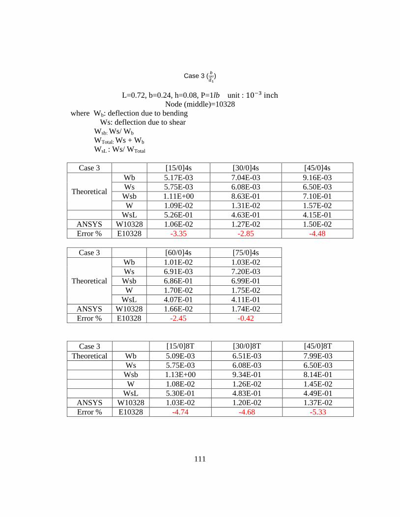
111
Case 3 (
)
L=0.72, b=0.24, h=0.08, P=1lb unit :
Node (middle)=10328
where Wb: deflection due to bending
Ws: deflection due to shear
Wsb: Ws/ Wb
WTotal: Ws + Wb
WsL : Ws/ WTotal
Case 3 [15/0]4s [30/0]4s [45/0]4s
Theoretical
Wb 5.17E-03 7.04E-03 9.16E-03
Ws 5.75E-03 6.08E-03 6.50E-03
Wsb 1.11E+00 8.63E-01 7.10E-01
W 1.09E-02 1.31E-02 1.57E-02
WsL 5.26E-01 4.63E-01 4.15E-01
ANSYS W10328 1.06E-02 1.27E-02 1.50E-02
Error % E10328 -3.35 -2.85 -4.48
Case 3 [60/0]4s [75/0]4s
Theoretical
Wb 1.01E-02 1.03E-02
Ws 6.91E-03 7.20E-03
Wsb 6.86E-01 6.99E-01
W 1.70E-02 1.75E-02
WsL 4.07E-01 4.11E-01
ANSYS W10328 1.66E-02 1.74E-02
Error % E10328 -2.45 -0.42
Case 3 [15/0]8T [30/0]8T [45/0]8T
Theoretical Wb 5.09E-03 6.51E-03 7.99E-03
Ws 5.75E-03 6.08E-03 6.50E-03
Wsb 1.13E+00 9.34E-01 8.14E-01
W 1.08E-02 1.26E-02 1.45E-02
WsL 5.30E-01 4.83E-01 4.49E-01
ANSYS W10328 1.03E-02 1.20E-02 1.37E-02
Error % E10328 -4.74 -4.68 -5.33
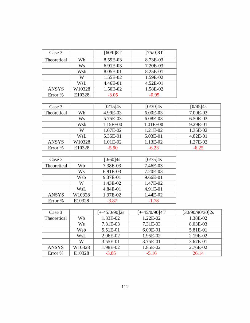
112
Case 3 [60/0]8T [75/0]8T
Theoretical Wb 8.59E-03 8.73E-03
Ws 6.91E-03 7.20E-03
Wsb 8.05E-01 8.25E-01
W 1.55E-02 1.59E-02
WsL 4.46E-01 4.52E-01
ANSYS W10328 1.50E-02 1.58E-02
Error % E10328 -3.05 -0.95
Case 3 [0/15]4s [0/30]4s [0/45]4s
Theoretical Wb 4.99E-03 6.00E-03 7.00E-03
Ws 5.75E-03 6.08E-03 6.50E-03
Wsb 1.15E+00 1.01E+00 9.29E-01
W 1.07E-02 1.21E-02 1.35E-02
WsL 5.35E-01 5.03E-01 4.82E-01
ANSYS W10328 1.01E-02 1.13E-02 1.27E-02
Error % E10328 -5.90 -6.23 -6.25
Case 3 [0/60]4s [0/75]4s
Theoretical Wb 7.38E-03 7.46E-03
Ws 6.91E-03 7.20E-03
Wsb 9.37E-01 9.66E-01
W 1.43E-02 1.47E-02
WsL 4.84E-01 4.91E-01
ANSYS W10328 1.37E-02 1.44E-02
Error % E10328 -3.87 -1.78
Case 3 [+-45/0/90]2s [+-45/0/90]4T [30/90/90/30]2s
Theoretical Wb 1.33E-02 1.22E-02 1.38E-02
Ws 7.31E-03 7.31E-03 8.03E-03
Wsb 5.51E-01 6.00E-01 5.81E-01
WsL 2.06E-02 1.95E-02 2.19E-02
W 3.55E-01 3.75E-01 3.67E-01
ANSYS W10328 1.98E-02 1.85E-02 2.76E-02
Error % E10328 -3.85 -5.16 26.14
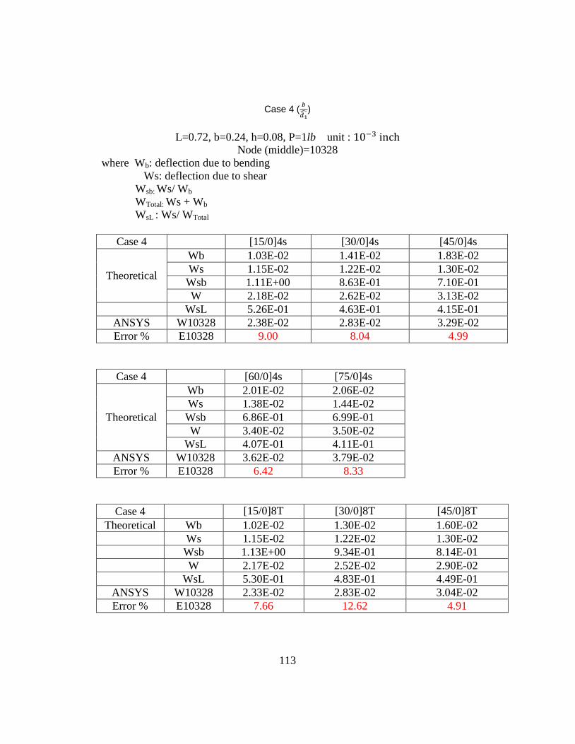
113
Case 4 (
)
L=0.72, b=0.24, h=0.08, P=1lb unit :
Node (middle)=10328
where Wb: deflection due to bending
Ws: deflection due to shear
Wsb: Ws/ Wb
WTotal: Ws + Wb
WsL : Ws/ WTotal
Case 4 [15/0]4s [30/0]4s [45/0]4s
Theoretical
Wb 1.03E-02 1.41E-02 1.83E-02
Ws 1.15E-02 1.22E-02 1.30E-02
Wsb 1.11E+00 8.63E-01 7.10E-01
W 2.18E-02 2.62E-02 3.13E-02
WsL 5.26E-01 4.63E-01 4.15E-01
ANSYS W10328 2.38E-02 2.83E-02 3.29E-02
Error % E10328 9.00 8.04 4.99
Case 4 [60/0]4s [75/0]4s
Theoretical
Wb 2.01E-02 2.06E-02
Ws 1.38E-02 1.44E-02
Wsb 6.86E-01 6.99E-01
W 3.40E-02 3.50E-02
WsL 4.07E-01 4.11E-01
ANSYS W10328 3.62E-02 3.79E-02
Error % E10328 6.42 8.33
Case 4 [15/0]8T [30/0]8T [45/0]8T
Theoretical Wb 1.02E-02 1.30E-02 1.60E-02
Ws 1.15E-02 1.22E-02 1.30E-02
Wsb 1.13E+00 9.34E-01 8.14E-01
W 2.17E-02 2.52E-02 2.90E-02
WsL 5.30E-01 4.83E-01 4.49E-01
ANSYS W10328 2.33E-02 2.83E-02 3.04E-02
Error % E10328 7.66 12.62 4.91
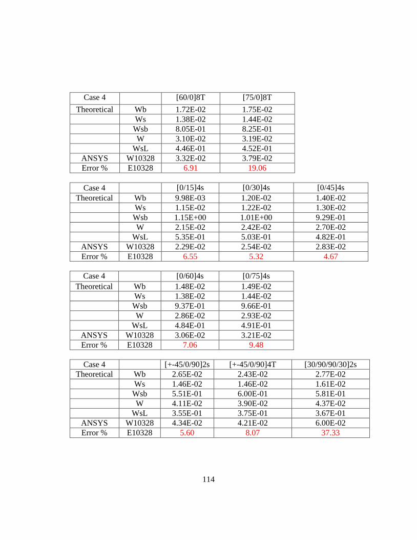
114
Case 4 [60/0]8T [75/0]8T
Theoretical Wb 1.72E-02 1.75E-02
Ws 1.38E-02 1.44E-02
Wsb 8.05E-01 8.25E-01
W 3.10E-02 3.19E-02
WsL 4.46E-01 4.52E-01
ANSYS W10328 3.32E-02 3.79E-02
Error % E10328 6.91 19.06
Case 4 [0/15]4s [0/30]4s [0/45]4s
Theoretical Wb 9.98E-03 1.20E-02 1.40E-02
Ws 1.15E-02 1.22E-02 1.30E-02
Wsb 1.15E+00 1.01E+00 9.29E-01
W 2.15E-02 2.42E-02 2.70E-02
WsL 5.35E-01 5.03E-01 4.82E-01
ANSYS W10328 2.29E-02 2.54E-02 2.83E-02
Error % E10328 6.55 5.32 4.67
Case 4 [0/60]4s [0/75]4s
Theoretical Wb 1.48E-02 1.49E-02
Ws 1.38E-02 1.44E-02
Wsb 9.37E-01 9.66E-01
W 2.86E-02 2.93E-02
WsL 4.84E-01 4.91E-01
ANSYS W10328 3.06E-02 3.21E-02
Error % E10328 7.06 9.48
Case 4 [+-45/0/90]2s [+-45/0/90]4T [30/90/90/30]2s
Theoretical Wb 2.65E-02 2.43E-02 2.77E-02
Ws 1.46E-02 1.46E-02 1.61E-02
Wsb 5.51E-01 6.00E-01 5.81E-01
W 4.11E-02 3.90E-02 4.37E-02
WsL 3.55E-01 3.75E-01 3.67E-01
ANSYS W10328 4.34E-02 4.21E-02 6.00E-02
Error % E10328 5.60 8.07 37.33
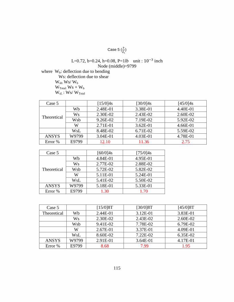
115
Case 5 (
)
L=0.72, b=0.24, h=0.08, P=1lb unit :
Node (middle)=9799
where Wb: deflection due to bending
Ws: deflection due to shear
Wsb: Ws/ Wb
WTotal: Ws + Wb
WsL : Ws/ WTotal
Case 5 [15/0]4s [30/0]4s [45/0]4s
Theoretical
Wb 2.48E-01 3.38E-01 4.40E-01
Ws 2.30E-02 2.43E-02 2.60E-02
Wsb 9.26E-02 7.19E-02 5.92E-02
W 2.71E-01 3.62E-01 4.66E-01
WsL 8.48E-02 6.71E-02 5.59E-02
ANSYS W9799 3.04E-01 4.03E-01 4.78E-01
Error % E9799 12.10 11.36 2.75
Case 5 [60/0]4s [75/0]4s
Theoretical
Wb 4.84E-01 4.95E-01
Ws 2.77E-02 2.88E-02
Wsb 5.72E-02 5.82E-02
W 5.11E-01 5.24E-01
WsL 5.41E-02 5.50E-02
ANSYS W9799 5.18E-01 5.33E-01
Error % E9799 1.30 1.70
Case 5 [15/0]8T [30/0]8T [45/0]8T
Theoretical Wb 2.44E-01 3.12E-01 3.83E-01
Ws 2.30E-02 2.43E-02 2.60E-02
Wsb 9.41E-02 7.78E-02 6.79E-02
W 2.67E-01 3.37E-01 4.09E-01
WsL 8.60E-02 7.22E-02 6.35E-02
ANSYS W9799 2.91E-01 3.64E-01 4.17E-01
Error % E9799 8.68 7.99 1.95
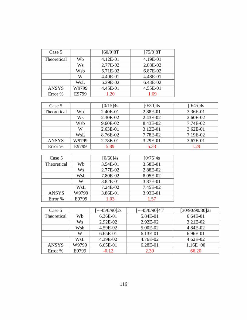
116
Case 5 [60/0]8T [75/0]8T
Theoretical Wb 4.12E-01 4.19E-01
Ws 2.77E-02 2.88E-02
Wsb 6.71E-02 6.87E-02
W 4.40E-01 4.48E-01
WsL 6.29E-02 6.43E-02
ANSYS W9799 4.45E-01 4.55E-01
Error % E9799 1.20 1.69
Case 5 [0/15]4s [0/30]4s [0/45]4s
Theoretical Wb 2.40E-01 2.88E-01 3.36E-01
Ws 2.30E-02 2.43E-02 2.60E-02
Wsb 9.60E-02 8.43E-02 7.74E-02
W 2.63E-01 3.12E-01 3.62E-01
WsL 8.76E-02 7.78E-02 7.19E-02
ANSYS W9799 2.78E-01 3.29E-01 3.67E-01
Error % E9799 5.89 5.33 1.29
Case 5 [0/60]4s [0/75]4s
Theoretical Wb 3.54E-01 3.58E-01
Ws 2.77E-02 2.88E-02
Wsb 7.80E-02 8.05E-02
W 3.82E-01 3.87E-01
WsL 7.24E-02 7.45E-02
ANSYS W9799 3.86E-01 3.93E-01
Error % E9799 1.03 1.57
Case 5 [+-45/0/90]2s [+-45/0/90]4T [30/90/90/30]2s
Theoretical Wb 6.36E-01 5.84E-01 6.64E-01
Ws 2.92E-02 2.92E-02 3.21E-02
Wsb 4.59E-02 5.00E-02 4.84E-02
W 6.65E-01 6.13E-01 6.96E-01
WsL 4.39E-02 4.76E-02 4.62E-02
ANSYS W9799 6.65E-01 6.28E-01 1.16E+00
Error % E9799 -0.12 2.30 66.20
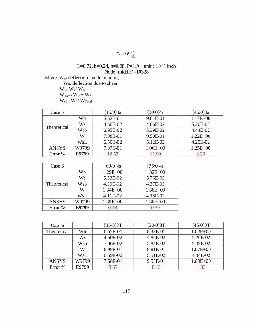
117
Case 6 (
)
L=0.72, b=0.24, h=0.08, P=1lb unit :
Node (middle)=10328
where Wb: deflection due to bending
Ws: deflection due to shear
Wsb: Ws/ Wb
WTotal: Ws + Wb
WsL : Ws/ WTotal
Case 6 [15/0]4s [30/0]4s [45/0]4s
Theoretical
Wb 6.62E-01 9.01E-01 1.17E+00
Ws 4.60E-02 4.86E-02 5.20E-02
Wsb 6.95E-02 5.39E-02 4.44E-02
W 7.08E-01 9.50E-01 1.22E+00
WsL 6.50E-02 5.12E-02 4.25E-02
ANSYS W9799 7.97E-01 1.06E+00 1.25E+00
Error % E9799 12.52 11.90 2.29
Case 6 [60/0]4s [75/0]4s
Theoretical
Wb 1.29E+00 1.32E+00
Ws 5.53E-02 5.76E-02
Wsb 4.29E-02 4.37E-02
W 1.34E+00 1.38E+00
WsL 4.11E-02 4.18E-02
ANSYS W9799 1.35E+00 1.38E+00
Error % E9799 0.18 0.30
Case 6 [15/0]8T [30/0]8T [45/0]8T
Theoretical Wb 6.52E-01 8.33E-01 1.02E+00
Ws 4.60E-02 4.86E-02 5.20E-02
Wsb 7.06E-02 5.84E-02 5.09E-02
W 6.98E-01 8.81E-01 1.07E+00
WsL 6.59E-02 5.51E-02 4.84E-02
ANSYS W9799 7.58E-01 9.53E-01 1.09E+00
Error % E9799 8.67 8.13 1.33
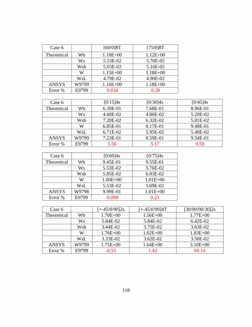
118
Case 6 [60/0]8T [75/0]8T
Theoretical Wb 1.10E+00 1.12E+00
Ws 5.53E-02 5.76E-02
Wsb 5.03E-02 5.16E-02
W 1.15E+00 1.18E+00
WsL 4.79E-02 4.90E-02
ANSYS W9799 1.16E+00 1.18E+00
Error % E9799 0.034 0.28
Case 6 [0/15]4s [0/30]4s [0/45]4s
Theoretical Wb 6.39E-01 7.68E-01 8.96E-01
Ws 4.60E-02 4.86E-02 5.20E-02
Wsb 7.20E-02 6.32E-02 5.81E-02
W 6.85E-01 8.17E-01 9.48E-01
WsL 6.71E-02 5.95E-02 5.49E-02
ANSYS W9799 7.23E-01 8.59E-01 9.54E-01
Error % E9799 5.56 5.17 0.59
Case 6 [0/60]4s [0/75]4s
Theoretical Wb 9.45E-01 9.55E-01
Ws 5.53E-02 5.76E-02
Wsb 5.85E-02 6.03E-02
W 1.00E+00 1.01E+00
WsL 5.53E-02 5.69E-02
ANSYS W9798 9.99E-01 1.01E+00
Error % E9799 -0.099 0.23
Case 6 [+-45/0/90]2s [+-45/0/90]4T [30/90/90/30]2s
Theoretical Wb 1.70E+00 1.56E+00 1.77E+00
Ws 5.84E-02 5.84E-02 6.42E-02
Wsb 3.44E-02 3.75E-02 3.63E-02
W 1.76E+00 1.62E+00 1.83E+00
WsL 3.33E-02 3.62E-02 3.50E-02
ANSYS W9799 1.75E+00 1.64E+00 3.10E+00
Error % E9799 -0.53 1.43 69.14

119
Appendix D
ANSYS Code for Case 1
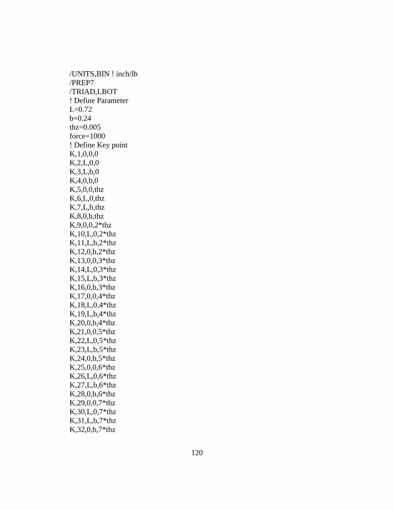
120
/UNITS,BIN ! inch/lb
/PREP7
/TRIAD,LBOT
! Define Parameter
L=0.72
b=0.24
thz=0.005
force=1000
! Define Key point
K,1,0,0,0
K,2,L,0,0
K,3,L,b,0
K,4,0,b,0
K,5,0,0,thz
K,6,L,0,thz
K,7,L,b,thz
K,8,0,b,thz
K,9,0,0,2*thz
K,10,L,0,2*thz
K,11,L,b,2*thz
K,12,0,b,2*thz
K,13,0,0,3*thz
K,14,L,0,3*thz
K,15,L,b,3*thz
K,16,0,b,3*thz
K,17,0,0,4*thz
K,18,L,0,4*thz
K,19,L,b,4*thz
K,20,0,b,4*thz
K,21,0,0,5*thz
K,22,L,0,5*thz
K,23,L,b,5*thz
K,24,0,b,5*thz
K,25,0,0,6*thz
K,26,L,0,6*thz
K,27,L,b,6*thz
K,28,0,b,6*thz
K,29,0,0,7*thz
K,30,L,0,7*thz
K,31,L,b,7*thz
K,32,0,b,7*thz
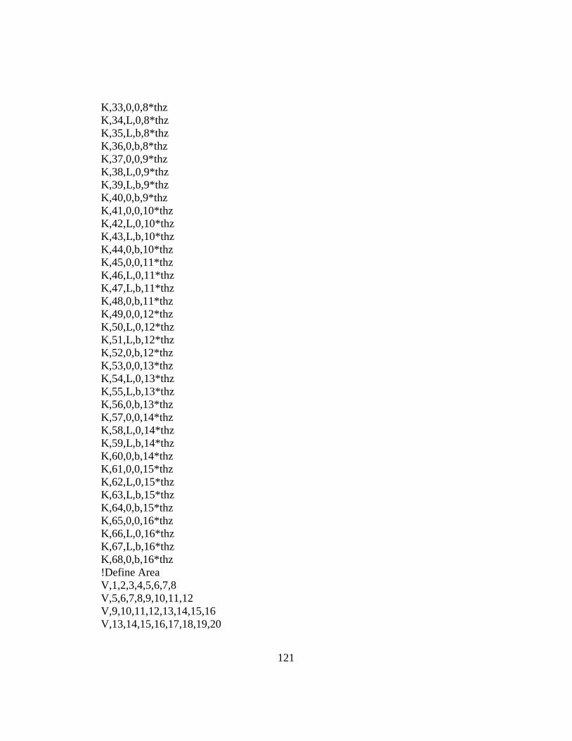
121
K,33,0,0,8*thz
K,34,L,0,8*thz
K,35,L,b,8*thz
K,36,0,b,8*thz
K,37,0,0,9*thz
K,38,L,0,9*thz
K,39,L,b,9*thz
K,40,0,b,9*thz
K,41,0,0,10*thz
K,42,L,0,10*thz
K,43,L,b,10*thz
K,44,0,b,10*thz
K,45,0,0,11*thz
K,46,L,0,11*thz
K,47,L,b,11*thz
K,48,0,b,11*thz
K,49,0,0,12*thz
K,50,L,0,12*thz
K,51,L,b,12*thz
K,52,0,b,12*thz
K,53,0,0,13*thz
K,54,L,0,13*thz
K,55,L,b,13*thz
K,56,0,b,13*thz
K,57,0,0,14*thz
K,58,L,0,14*thz
K,59,L,b,14*thz
K,60,0,b,14*thz
K,61,0,0,15*thz
K,62,L,0,15*thz
K,63,L,b,15*thz
K,64,0,b,15*thz
K,65,0,0,16*thz
K,66,L,0,16*thz
K,67,L,b,16*thz
K,68,0,b,16*thz
!Define Area
V,1,2,3,4,5,6,7,8
V,5,6,7,8,9,10,11,12
V,9,10,11,12,13,14,15,16
V,13,14,15,16,17,18,19,20
122
V,17,18,19,20,21,22,23,24
V,21,22,23,24,25,26,27,28
V,25,26,27,28,29,30,31,32
V,29,30,31,32,33,34,35,36
V,33,34,35,36,37,38,39,40
V,37,38,39,40,41,42,43,44
V,41,42,43,44,45,46,47,48
V,45,46,47,48,49,50,51,52
V,49,50,51,52,53,54,55,56
V,53,54,55,56,57,58,59,60
V,57,58,59,60,61,62,63,64
V,61,62,63,64,65,66,67,68
VGLUE,ALL
! Define Material Properties
ET,1,SOLID186
KEYOPT,1,2,0
KEYOPT,1,3,1
KEYOPT,1,6,1
MP,EX,1,20.3e6
MP,EY,1,1.5e6
MP,EZ,1,1.5e6
MP,PRXY,1,0.27
MP,PRYZ,1,0.54
MP,PRXZ,1,0.27
MP,GXY,1,1e6
MP,GYZ,1,0.54e6
MP,GXZ,1,1e6
local,26,,0,0,0,75
local,25,,0,0,0,-75
local,24,,0,0,0,75
local,23,,0,0,0,-75
local,22,,0,0,0,75
local,21,,0,0,0,-75
local,20,,0,0,0,75
local,19,,0,0,0,-75
local,18,,0,0,0,-75
local,17,,0,0,0,75
local,16,,0,0,0,-75
local,15,,0,0,0,75
local,14,,0,0,0,-75
123
local,13,,0,0,0,75
local,12,,0,0,0,-75
local,11,,0,0,0,75
CSYS,0
! Mesh Attribute & SIZE CONTROL & MESH
VSEL,S,VOLU,,1
VATT,1,,1,11,1
LSEL,S,LINE,,1
LSEL,A,LINE,,3
LSEL,A,LINE,,6
LSEL,A,LINE,,10
LESIZE,ALL,,,18,1
LSEL,S,LINE,,2
LSEL,A,LINE,,4
LSEL,A,LINE,,8
LSEL,A,LINE,,12
LESIZE,ALL,,,16,1
LSEL,S,LINE,,5
LSEL,A,LINE,,7
LSEL,A,LINE,,9
LSEL,A,LINE,,11
LESIZE,ALL,,,1,1
VMESH,ALL
VSEL,S,VOLU,,2
VATT,1,,1,12,2
LSEL,S,LINE,,6
LSEL,A,LINE,,10
LSEL,A,LINE,,14
LSEL,A,LINE,,18
LESIZE,ALL,,,18,1
LSEL,S,LINE,,8
LSEL,A,LINE,,12
LSEL,A,LINE,,16
LSEL,A,LINE,,20
LESIZE,ALL,,,16,1
LSEL,S,LINE,,13
124
LSEL,A,LINE,,15
LSEL,A,LINE,,17
LSEL,A,LINE,,19
LESIZE,ALL,,,1,1
VMESH,ALL
VSEL,S,VOLU,,3
VATT,1,,1,13,3
LSEL,S,LINE,,14
LSEL,A,LINE,,18
LSEL,A,LINE,,22
LSEL,A,LINE,,26
LESIZE,ALL,,,18,1
LSEL,S,LINE,,16
LSEL,A,LINE,,20
LSEL,A,LINE,,24
LSEL,A,LINE,,28
LESIZE,ALL,,,16,1
LSEL,S,LINE,,21
LSEL,A,LINE,,23
LSEL,A,LINE,,25
LSEL,A,LINE,,27
LESIZE,ALL,,,1,1
VMESH,ALL
VSEL,S,VOLU,,4
VATT,1,,1,14,4
LSEL,S,LINE,,22
LSEL,A,LINE,,26
LSEL,A,LINE,,30
LSEL,A,LINE,,34
LESIZE,ALL,,,18,1
LSEL,S,LINE,,24
LSEL,A,LINE,,28
LSEL,A,LINE,,32
LSEL,A,LINE,,36
LESIZE,ALL,,,16,1
125
LSEL,S,LINE,,29
LSEL,A,LINE,,31
LSEL,A,LINE,,33
LSEL,A,LINE,,35
LESIZE,ALL,,,1,1
VMESH,ALL
VSEL,S,VOLU,,5
VATT,1,,1,15,5
LSEL,S,LINE,,30
LSEL,A,LINE,,34
LSEL,A,LINE,,38
LSEL,A,LINE,,42
LESIZE,ALL,,,18,1
LSEL,S,LINE,,32
LSEL,A,LINE,,36
LSEL,A,LINE,,40
LSEL,A,LINE,,44
LESIZE,ALL,,,16,1
LSEL,S,LINE,,37
LSEL,A,LINE,,39
LSEL,A,LINE,,41
LSEL,A,LINE,,43
LESIZE,ALL,,,1,1
VMESH,ALL
VSEL,S,VOLU,,6
VATT,1,,1,16,6
LSEL,S,LINE,,38
LSEL,A,LINE,,42
LSEL,A,LINE,,46
LSEL,A,LINE,,50
LESIZE,ALL,,,18,1
LSEL,S,LINE,,40
LSEL,A,LINE,,42
126
LSEL,A,LINE,,48
LSEL,A,LINE,,52
LESIZE,ALL,,,16,1
LSEL,S,LINE,,45
LSEL,A,LINE,,47
LSEL,A,LINE,,49
LSEL,A,LINE,,51
LESIZE,ALL,,,1,1
VMESH,ALL
VSEL,S,VOLU,,7
VATT,1,,1,17,7
LSEL,S,LINE,,46
LSEL,A,LINE,,50
LSEL,A,LINE,,54
LSEL,A,LINE,,58
LESIZE,ALL,,,18,1
LSEL,S,LINE,,48
LSEL,A,LINE,,52
LSEL,A,LINE,,56
LSEL,A,LINE,,60
LESIZE,ALL,,,16,1
LSEL,S,LINE,,53
LSEL,A,LINE,,55
LSEL,A,LINE,,57
LSEL,A,LINE,,59
LESIZE,ALL,,,1,1
VMESH,ALL
VSEL,S,VOLU,,8
VATT,1,,1,18,8
LSEL,S,LINE,,54
LSEL,A,LINE,,58
LSEL,A,LINE,,62
LSEL,A,LINE,,66
LESIZE,ALL,,,18,1
127
LSEL,S,LINE,,56
LSEL,A,LINE,,60
LSEL,A,LINE,,64
LSEL,A,LINE,,68
LESIZE,ALL,,,16,1
LSEL,S,LINE,,61
LSEL,A,LINE,,63
LSEL,A,LINE,,65
LSEL,A,LINE,,67
LESIZE,ALL,,,1,1
VMESH,ALL
VSEL,S,VOLU,,9
VATT,1,,1,19,9
LSEL,S,LINE,,62
LSEL,A,LINE,,66
LSEL,A,LINE,,70
LSEL,A,LINE,,74
LESIZE,ALL,,,18,1
LSEL,S,LINE,,64
LSEL,A,LINE,,68
LSEL,A,LINE,,72
LSEL,A,LINE,,76
LESIZE,ALL,,,16,1
LSEL,S,LINE,,69
LSEL,A,LINE,,71
LSEL,A,LINE,,73
LSEL,A,LINE,,75
LESIZE,ALL,,,1,1
VMESH,ALL
VSEL,S,VOLU,,10
VATT,1,,1,20,10
LSEL,S,LINE,,70
LSEL,A,LINE,,74
128
LSEL,A,LINE,,78
LSEL,A,LINE,,82
LESIZE,ALL,,,18,1
LSEL,S,LINE,,72
LSEL,A,LINE,,76
LSEL,A,LINE,,80
LSEL,A,LINE,,84
LESIZE,ALL,,,16,1
LSEL,S,LINE,,77
LSEL,A,LINE,,79
LSEL,A,LINE,,81
LSEL,A,LINE,,83
LESIZE,ALL,,,1,1
VMESH,ALL
VSEL,S,VOLU,,11
VATT,1,,1,21,11
LSEL,S,LINE,,78
LSEL,A,LINE,,82
LSEL,A,LINE,,86
LSEL,A,LINE,,90
LESIZE,ALL,,,18,1
LSEL,S,LINE,,80
LSEL,A,LINE,,84
LSEL,A,LINE,,88
LSEL,A,LINE,,92
LESIZE,ALL,,,16,1
LSEL,S,LINE,,85
LSEL,A,LINE,,87
LSEL,A,LINE,,89
LSEL,A,LINE,,91
LESIZE,ALL,,,1,1
VMESH,ALL
VSEL,S,VOLU,,12
VATT,1,,1,22,12
129
LSEL,S,LINE,,86
LSEL,A,LINE,,90
LSEL,A,LINE,,94
LSEL,A,LINE,,98
LESIZE,ALL,,,18,1
LSEL,S,LINE,,88
LSEL,A,LINE,,92
LSEL,A,LINE,,96
LSEL,A,LINE,,100
LESIZE,ALL,,,16,1
LSEL,S,LINE,,93
LSEL,A,LINE,,95
LSEL,A,LINE,,97
LSEL,A,LINE,,99
LESIZE,ALL,,,1,1
VMESH,ALL
VSEL,S,VOLU,,13
VATT,1,,1,23,13
LSEL,S,LINE,,94
LSEL,A,LINE,,98
LSEL,A,LINE,,102
LSEL,A,LINE,,106
LESIZE,ALL,,,18,1
LSEL,S,LINE,,96
LSEL,A,LINE,,100
LSEL,A,LINE,,104
LSEL,A,LINE,,108
LESIZE,ALL,,,16,1
LSEL,S,LINE,,101
LSEL,A,LINE,,103
LSEL,A,LINE,,105
LSEL,A,LINE,,107
LESIZE,ALL,,,1,1
VMESH,ALL
130
VSEL,S,VOLU,,14
VATT,1,,1,24,14
LSEL,S,LINE,,102
LSEL,A,LINE,,106
LSEL,A,LINE,,110
LSEL,A,LINE,,114
LESIZE,ALL,,,18,1
LSEL,S,LINE,,104
LSEL,A,LINE,,108
LSEL,A,LINE,,112
LSEL,A,LINE,,116
LESIZE,ALL,,,16,1
LSEL,S,LINE,,109
LSEL,A,LINE,,111
LSEL,A,LINE,,113
LSEL,A,LINE,,115
LESIZE,ALL,,,1,1
VMESH,ALL
VSEL,S,VOLU,,15
VATT,1,,1,25,15
LSEL,S,LINE,,110
LSEL,A,LINE,,114
LSEL,A,LINE,,118
LSEL,A,LINE,,122
LESIZE,ALL,,,18,1
LSEL,S,LINE,,112
LSEL,A,LINE,,116
LSEL,A,LINE,,120
LSEL,A,LINE,,124
LESIZE,ALL,,,16,1
LSEL,S,LINE,,117
LSEL,A,LINE,,119
LSEL,A,LINE,,121
131
LSEL,A,LINE,,123
LESIZE,ALL,,,1,1
VMESH,ALL
VSEL,S,VOLU,,16
VATT,1,,1,26,16
LSEL,S,LINE,,118
LSEL,A,LINE,,122
LSEL,A,LINE,,126
LSEL,A,LINE,,130
LESIZE,ALL,,,18,1
LSEL,S,LINE,,120
LSEL,A,LINE,,124
LSEL,A,LINE,,128
LSEL,A,LINE,,132
LESIZE,ALL,,,16,1
LSEL,S,LINE,,125
LSEL,A,LINE,,127
LSEL,A,LINE,,129
LSEL,A,LINE,,131
LESIZE,ALL,,,1,1
VMESH,ALL
FLST,2,33,1,ORDE,4
FITEM,2,9726
FITEM,2,9782
FITEM,2,9784
FITEM,2,-9814
!*
/GO
D,P51X, ,0, , , ,UZ, , , , ,
FLST,2,33,1,ORDE,4
FITEM,2,9728
FITEM,2,9830
132
FITEM,2,9884
FITEM,2,-9914
!*
/GO
D,P51X, ,0, , , ,UX,UY,UZ, , ,
FLST,2,933,1,ORDE,12
FITEM,2,19774
FITEM,2,19776
FITEM,2,-19811
FITEM,2,19830
FITEM,2,19832
FITEM,2,-19862
FITEM,2,19878
FITEM,2,-19913
FITEM,2,19932
FITEM,2,-19962
FITEM,2,19978
FITEM,2,-20774
!*
/GO
F,P51X,FZ,force/933
/SOL
ANTYPE,STATIC
SOLVE
/REPLOT,RESIZE
WPSTYLE,,,,,,,,0
FINISH
/POST1
!*
PRNSOL,U,Z

133
Appendix E
MATLAB Code
134
% Composite Material
% PART 1 Equivalent ABD matrix
clear;
clc;
%input data
format long
E1=20.3e6;
E2=1.5e6;
E3=1.5e6;
v12=0.27;
v13=0.27;
v23=0.54;
G12=1e6;
G13=1e6;
G23=0.54e6;
tply=0.005;
% Dimensions
L=0.72;
bw=0.24;
layers=16;
h=tply*layers;
tply=0.005;
A=bw*(h);
P=1000;
thickness=16*tply;
Vf=1/16;
% Q
S=zeros(6,6);
S(1,1)=1/E1;
S(2,2)=1/E2;
S(3,3)=1/E3;
S(4,4)=1/G23;
S(5,5)=1/G13;
S(6,6)=1/G12;
S(1,2)=-v12./E1;
S(1,3)=-v13./E1;
S(2,1)=-v12./E1;
S(2,3)=-v23./E2;
S(3,1)=-v13./E1;
135
S(3,2)=-v23./E2;
% C matrix
C_bar=inv(S);
C44=C_bar(4,4);
C55=C_bar(5,5);
% C_bar@0deg rotate with z-axis
ANGLE_1=0;
A_1=ANGLE_1*pi/180;
m=cos(A_1);
n=sin(A_1);
Tstress=[m^2 n^2 0 0 0 2*m*n
n^2 m^2 0 0 0 -2*m*n
0 0 1 0 0 0
0 0 0 m -n 0
0 0 0 n m 0
-m*n m*n 0 0 0 m^2-n^2];
Tstrain=[m^2 n^2 0 0 0 m*n
n^2 m^2 0 0 0 -m*n
0 0 1 0 0 0
0 0 0 m -n 0
0 0 0 n m 0
-2*m*n 2*m*n 0 0 0 m^2-n^2];
C_bar_0=inv(Tstress)*C_bar*Tstrain;
C55_0=C_bar_0(5,5); % C55=G13
c0=[C_bar_0(4,4) C_bar_0(4,5);
C_bar_0(5,4) C_bar_0(5,5)];
% C_bar@15deg rotate with z-axis
ANGLE_1=15;
A_1=ANGLE_1*pi/180;
m=cos(A_1);
n=sin(A_1);
Tstress=[m^2 n^2 0 0 0 2*m*n
n^2 m^2 0 0 0 -2*m*n
0 0 1 0 0 0
0 0 0 m -n 0
0 0 0 n m 0
-m*n m*n 0 0 0 m^2-n^2];
Tstrain=[m^2 n^2 0 0 0 m*n
136
n^2 m^2 0 0 0 -m*n
0 0 1 0 0 0
0 0 0 m -n 0
0 0 0 n m 0
-2*m*n 2*m*n 0 0 0 m^2-n^2];
C_bar_15=inv(Tstress)*C_bar*Tstrain;
C55_15=C_bar_15(5,5); % C55=G13
C5515=(n^2)*C44+(m^2)*C55;
C4415=(m^2)*C44+(n^2)*C55;
C4515=(C55-C44)*m*n;
c15=[C_bar_15(4,4) C_bar_15(4,5);
C_bar_15(5,4) C_bar_15(5,5)];
% C_bar@-15deg rotate with z-axis
ANGLE_1=-15;
A_1=ANGLE_1*pi/180;
m=cos(A_1);
n=sin(A_1);
Tstress=[m^2 n^2 0 0 0 2*m*n
n^2 m^2 0 0 0 -2*m*n
0 0 1 0 0 0
0 0 0 m -n 0
0 0 0 n m 0
-m*n m*n 0 0 0 m^2-n^2];
Tstrain=[m^2 n^2 0 0 0 m*n
n^2 m^2 0 0 0 -m*n
0 0 1 0 0 0
0 0 0 m -n 0
0 0 0 n m 0
-2*m*n 2*m*n 0 0 0 m^2-n^2];
C_bar_115=inv(Tstress)*C_bar*Tstrain;
C55_115=C_bar_115(5,5); % C55=G13
c115=[C_bar_115(4,4) C_bar_115(4,5);
C_bar_115(5,4) C_bar_115(5,5)];
% C_bar@30deg rotate with z-axis
ANGLE_1=30;
A_1=ANGLE_1*pi/180;
m=cos(A_1);
n=sin(A_1);
Tstress=[m^2 n^2 0 0 0 2*m*n
n^2 m^2 0 0 0 -2*m*n
137
0 0 1 0 0 0
0 0 0 m -n 0
0 0 0 n m 0
-m*n m*n 0 0 0 m^2-n^2];
Tstrain=[m^2 n^2 0 0 0 m*n
n^2 m^2 0 0 0 -m*n
0 0 1 0 0 0
0 0 0 m -n 0
0 0 0 n m 0
-2*m*n 2*m*n 0 0 0 m^2-n^2];
C_bar_30=inv(Tstress)*C_bar*Tstrain;
C55_30=C_bar_30(5,5); % C55=G13
C5530=(n^2)*C44+(m^2)*C55;
c30=[C_bar_30(4,4) C_bar_30(4,5);
C_bar_30(5,4) C_bar_30(5,5)];
% C_bar@-30deg rotate with z-axis
ANGLE_1=-30;
A_1=ANGLE_1*pi/180;
m=cos(A_1);
n=sin(A_1);
Tstress=[m^2 n^2 0 0 0 2*m*n
n^2 m^2 0 0 0 -2*m*n
0 0 1 0 0 0
0 0 0 m -n 0
0 0 0 n m 0
-m*n m*n 0 0 0 m^2-n^2];
Tstrain=[m^2 n^2 0 0 0 m*n
n^2 m^2 0 0 0 -m*n
0 0 1 0 0 0
0 0 0 m -n 0
0 0 0 n m 0
-2*m*n 2*m*n 0 0 0 m^2-n^2];
C_bar_330=inv(Tstress)*C_bar*Tstrain;
C55_330=C_bar_330(5,5); % C55=G13
c330=[C_bar_330(4,4) C_bar_330(4,5);
C_bar_330(5,4) C_bar_330(5,5)];
% C_bar@45deg rotate with z-axis
ANGLE_1=45;
A_1=ANGLE_1*pi/180;
m=cos(A_1);
138
n=sin(A_1);
Tstress=[m^2 n^2 0 0 0 2*m*n
n^2 m^2 0 0 0 -2*m*n
0 0 1 0 0 0
0 0 0 m -n 0
0 0 0 n m 0
-m*n m*n 0 0 0 m^2-n^2];
Tstrain=[m^2 n^2 0 0 0 m*n
n^2 m^2 0 0 0 -m*n
0 0 1 0 0 0
0 0 0 m -n 0
0 0 0 n m 0
-2*m*n 2*m*n 0 0 0 m^2-n^2];
C_bar_45=inv(Tstress)*C_bar*Tstrain;
C55_45=C_bar_45(5,5); % C55=G13
c45=[C_bar_45(4,4) C_bar_45(4,5);
C_bar_45(5,4) C_bar_45(5,5)];
% C_bar@-45deg rotate with z-axis
ANGLE_1=-45;
A_1=ANGLE_1*pi/180;
m=cos(A_1);
n=sin(A_1);
Tstress=[m^2 n^2 0 0 0 2*m*n
n^2 m^2 0 0 0 -2*m*n
0 0 1 0 0 0
0 0 0 m -n 0
0 0 0 n m 0
-m*n m*n 0 0 0 m^2-n^2];
Tstrain=[m^2 n^2 0 0 0 m*n
n^2 m^2 0 0 0 -m*n
0 0 1 0 0 0
0 0 0 m -n 0
0 0 0 n m 0
-2*m*n 2*m*n 0 0 0 m^2-n^2];
C_bar_445=inv(Tstress)*C_bar*Tstrain;
C55_445=C_bar_445(5,5); % C55=G13
c445=[C_bar_445(4,4) C_bar_445(4,5);
C_bar_445(5,4) C_bar_445(5,5)];
% C_bar@60deg rotate with z-axis
139
ANGLE_1=60;
A_1=ANGLE_1*pi/180;
m=cos(A_1);
n=sin(A_1);
Tstress=[m^2 n^2 0 0 0 2*m*n
n^2 m^2 0 0 0 -2*m*n
0 0 1 0 0 0
0 0 0 m -n 0
0 0 0 n m 0
-m*n m*n 0 0 0 m^2-n^2];
Tstrain=[m^2 n^2 0 0 0 m*n
n^2 m^2 0 0 0 -m*n
0 0 1 0 0 0
0 0 0 m -n 0
0 0 0 n m 0
-2*m*n 2*m*n 0 0 0 m^2-n^2];
C_bar_60=inv(Tstress)*C_bar*Tstrain;
C55_60=C_bar_60(5,5); % C55=G13
c60=[C_bar_60(4,4) C_bar_60(4,5);
C_bar_60(5,4) C_bar_60(5,5)];
% C_bar@-60deg rotate with z-axis
ANGLE_1=-60;
A_1=ANGLE_1*pi/180;
m=cos(A_1);
n=sin(A_1);
Tstress=[m^2 n^2 0 0 0 2*m*n
n^2 m^2 0 0 0 -2*m*n
0 0 1 0 0 0
0 0 0 m -n 0
0 0 0 n m 0
-m*n m*n 0 0 0 m^2-n^2];
Tstrain=[m^2 n^2 0 0 0 m*n
n^2 m^2 0 0 0 -m*n
0 0 1 0 0 0
0 0 0 m -n 0
0 0 0 n m 0
-2*m*n 2*m*n 0 0 0 m^2-n^2];
C_bar_660=inv(Tstress)*C_bar*Tstrain;
C55_660=C_bar_660(5,5); % C55=G13
c660=[C_bar_660(4,4) C_bar_660(4,5);
140
C_bar_660(5,4) C_bar_660(5,5)];
% C_bar@75deg rotate with z-axis
ANGLE_1=75;
A_1=ANGLE_1*pi/180;
m=cos(A_1);
n=sin(A_1);
Tstress=[m^2 n^2 0 0 0 2*m*n
n^2 m^2 0 0 0 -2*m*n
0 0 1 0 0 0
0 0 0 m -n 0
0 0 0 n m 0
-m*n m*n 0 0 0 m^2-n^2];
Tstrain=[m^2 n^2 0 0 0 m*n
n^2 m^2 0 0 0 -m*n
0 0 1 0 0 0
0 0 0 m -n 0
0 0 0 n m 0
-2*m*n 2*m*n 0 0 0 m^2-n^2];
C_bar_75=inv(Tstress)*C_bar*Tstrain;
C55_75=C_bar_75(5,5); % C55=G13
c75=[C_bar_75(4,4) C_bar_75(4,5);
C_bar_75(5,4) C_bar_75(5,5)];
% C_bar@-75deg rotate with z-axis
ANGLE_1=-75;
A_1=ANGLE_1*pi/180;
m=cos(A_1);
n=sin(A_1);
Tstress=[m^2 n^2 0 0 0 2*m*n
n^2 m^2 0 0 0 -2*m*n
0 0 1 0 0 0
0 0 0 m -n 0
0 0 0 n m 0
-m*n m*n 0 0 0 m^2-n^2];
Tstrain=[m^2 n^2 0 0 0 m*n
n^2 m^2 0 0 0 -m*n
0 0 1 0 0 0
0 0 0 m -n 0
0 0 0 n m 0
-2*m*n 2*m*n 0 0 0 m^2-n^2];
141
C_bar_775=inv(Tstress)*C_bar*Tstrain;
C55_775=C_bar_775(5,5); % C55=G13
c775=[C_bar_775(4,4) C_bar_775(4,5);
C_bar_775(5,4) C_bar_775(5,5)];
% C_bar@90deg rotate with z-axis
ANGLE_1=90;
A_1=ANGLE_1*pi/180;
m=cos(A_1);
n=sin(A_1);
Tstress=[m^2 n^2 0 0 0 2*m*n
n^2 m^2 0 0 0 -2*m*n
0 0 1 0 0 0
0 0 0 m -n 0
0 0 0 n m 0
-m*n m*n 0 0 0 m^2-n^2];
Tstrain=[m^2 n^2 0 0 0 m*n
n^2 m^2 0 0 0 -m*n
0 0 1 0 0 0
0 0 0 m -n 0
0 0 0 n m 0
-2*m*n 2*m*n 0 0 0 m^2-n^2];
C_bar_90=inv(Tstress)*C_bar*Tstrain;
C55_90=C_bar_90(5,5); % C55=G13
c90=[C_bar_90(4,4) C_bar_90(4,5);
C_bar_90(5,4) C_bar_90(5,5)];
% C_bar@-90deg rotate with z-axis
ANGLE_1=-90;
A_1=ANGLE_1*pi/180;
m=cos(A_1);
n=sin(A_1);
Tstress=[m^2 n^2 0 0 0 2*m*n
n^2 m^2 0 0 0 -2*m*n
0 0 1 0 0 0
0 0 0 m -n 0
0 0 0 n m 0
-m*n m*n 0 0 0 m^2-n^2];
Tstrain=[m^2 n^2 0 0 0 m*n
n^2 m^2 0 0 0 -m*n
0 0 1 0 0 0
142
0 0 0 m -n 0
0 0 0 n m 0
-2*m*n 2*m*n 0 0 0 m^2-n^2];
C_bar_990=inv(Tstress)*C_bar*Tstrain;
C55_990=C_bar_990(5,5); % C55=G13
c990=[C_bar_990(4,4) C_bar_990(4,5);
C_bar_990(5,4) C_bar_990(5,5)];
%Laminate 1
h0=-8*tply;
h1=-7*tply;
h2=-6*tply;
h3=-5*tply;
h4=-4*tply;
h5=-3*tply;
h6=-2*tply;
h7=-1*tply;
h8=0*tply;
h9=1*tply;
h10=2*tply;
h11=3*tply;
h12=4*tply;
h13=5*tply;
h14=6*tply;
h15=7*tply;
h16=8*tply;
% Q
S=zeros(3,3);
S(1,1)=1/E1;
S(2,2)=1/E2;
S(3,3)=1/G12;
S(1,2)=-v12./E1;
S(2,1)=-v12./E1;
% Q matrix
Q_bar=inv(S);
% Q_bar@45deg
ANGLE_1=45;
A_1=ANGLE_1*pi/180;
m=cos(A_1);
n=sin(A_1);
143
Tstress=[m^2 n^2 2*m*n
n^2 m^2 -2*m*n
-m*n m*n m^2-n^2];
Tstrain=[m^2 n^2 m*n
n^2 m^2 -m*n
-2*m*n 2*m*n m^2-n^2];
Q_bar_45=inv(Tstress)*Q_bar*Tstrain;
% Q_bar@-45deg
ANGLE_1=-45;
A_1=ANGLE_1*pi/180;
m=cos(A_1);
n=sin(A_1);
Tstress=[m^2 n^2 2*m*n
n^2 m^2 -2*m*n
-m*n m*n m^2-n^2];
Tstrain=[m^2 n^2 m*n
n^2 m^2 -m*n
-2*m*n 2*m*n m^2-n^2];
Q_bar_445=inv(Tstress)*Q_bar*Tstrain;
% Q_bar@0deg
ANGLE_1=0;
A_1=ANGLE_1*pi/180;
m=cos(A_1);
n=sin(A_1);
Tstress=[m^2 n^2 2*m*n
n^2 m^2 -2*m*n
-m*n m*n m^2-n^2];
Tstrain=[m^2 n^2 m*n
n^2 m^2 -m*n
-2*m*n 2*m*n m^2-n^2];
Q_bar_0=inv(Tstress)*Q_bar*Tstrain;
% Q_bar@90deg
ANGLE_1=90;
A_1=ANGLE_1*pi/180;
m=cos(A_1);
n=sin(A_1);
Tstress=[m^2 n^2 2*m*n
n^2 m^2 -2*m*n
-m*n m*n m^2-n^2];
Tstrain=[m^2 n^2 m*n
n^2 m^2 -m*n
144
-2*m*n 2*m*n m^2-n^2];
Q_bar_90=inv(Tstress)*Q_bar*Tstrain;
% Q_bar@30deg
ANGLE_1=30;
A_1=ANGLE_1*pi/180;
m=cos(A_1);
n=sin(A_1);
Tstress=[m^2 n^2 2*m*n
n^2 m^2 -2*m*n
-m*n m*n m^2-n^2];
Tstrain=[m^2 n^2 m*n
n^2 m^2 -m*n
-2*m*n 2*m*n m^2-n^2];
Q_bar_30=inv(Tstress)*Q_bar*Tstrain;
% Q_bar@-30deg
ANGLE_1=-30;
A_1=ANGLE_1*pi/180;
m=cos(A_1);
n=sin(A_1);
Tstress=[m^2 n^2 2*m*n
n^2 m^2 -2*m*n
-m*n m*n m^2-n^2];
Tstrain=[m^2 n^2 m*n
n^2 m^2 -m*n
-2*m*n 2*m*n m^2-n^2];
Q_bar_330=inv(Tstress)*Q_bar*Tstrain;
% Q_bar@60deg
ANGLE_1=60;
A_1=ANGLE_1*pi/180;
m=cos(A_1);
n=sin(A_1);
Tstress=[m^2 n^2 2*m*n
n^2 m^2 -2*m*n
-m*n m*n m^2-n^2];
Tstrain=[m^2 n^2 m*n
n^2 m^2 -m*n
-2*m*n 2*m*n m^2-n^2];
Q_bar_60=inv(Tstress)*Q_bar*Tstrain;
% Q_bar@-60deg
ANGLE_1=-60;
A_1=ANGLE_1*pi/180;
145
m=cos(A_1);
n=sin(A_1);
Tstress=[m^2 n^2 2*m*n
n^2 m^2 -2*m*n
-m*n m*n m^2-n^2];
Tstrain=[m^2 n^2 m*n
n^2 m^2 -m*n
-2*m*n 2*m*n m^2-n^2];
Q_bar_660=inv(Tstress)*Q_bar*Tstrain;
% Q_bar@15deg
ANGLE_1=15;
A_1=ANGLE_1*pi/180;
m=cos(A_1);
n=sin(A_1);
Tstress=[m^2 n^2 2*m*n
n^2 m^2 -2*m*n
-m*n m*n m^2-n^2];
Tstrain=[m^2 n^2 m*n
n^2 m^2 -m*n
-2*m*n 2*m*n m^2-n^2];
Q_bar_15=inv(Tstress)*Q_bar*Tstrain;
% Q_bar@-15deg
ANGLE_1=-15;
A_1=ANGLE_1*pi/180;
m=cos(A_1);
n=sin(A_1);
Tstress=[m^2 n^2 2*m*n
n^2 m^2 -2*m*n
-m*n m*n m^2-n^2];
Tstrain=[m^2 n^2 m*n
n^2 m^2 -m*n
-2*m*n 2*m*n m^2-n^2];
Q_bar_115=inv(Tstress)*Q_bar*Tstrain;
% Q_bar@75deg
ANGLE_1=75;
A_1=ANGLE_1*pi/180;
m=cos(A_1);
n=sin(A_1);
Tstress=[m^2 n^2 2*m*n
n^2 m^2 -2*m*n
-m*n m*n m^2-n^2];
146
Tstrain=[m^2 n^2 m*n
n^2 m^2 -m*n
-2*m*n 2*m*n m^2-n^2];
Q_bar_75=inv(Tstress)*Q_bar*Tstrain;
% Q_bar@-75deg
ANGLE_1=-75;
A_1=ANGLE_1*pi/180;
m=cos(A_1);
n=sin(A_1);
Tstress=[m^2 n^2 2*m*n
n^2 m^2 -2*m*n
-m*n m*n m^2-n^2];
Tstrain=[m^2 n^2 m*n
n^2 m^2 -m*n
-2*m*n 2*m*n m^2-n^2];
Q_bar_775=inv(Tstress)*Q_bar*Tstrain;
%1 [+-45/0/90]4T C_bar_90 C_bar_0 C_bar_445 C_bar_45 C_bar_90
C_bar_0 C_bar_445 C_bar_45 C_bar_90 C_bar_0 C_bar_445 C_bar_45
C_bar_90 C_bar_0 C_bar_445 C_bar_45
% Q_bar_90 Q_bar_0 Q_bar_445 Q_bar_45 Q_bar_90 Q_bar_0
Q_bar_445 Q_bar_45 Q_bar_90 Q_bar_0 Q_bar_445 Q_bar_45 Q_bar_90
Q_bar_0 Q_bar_445 Q_bar_45
%2 [+-45/0/90]2T C_bar_90 C_bar_0 C_bar_445 C_bar_45 C_bar_90
C_bar_0 C_bar_445 C_bar_45
% Q_bar_90 Q_bar_0 Q_bar_445 Q_bar_45 Q_bar_90 Q_bar_0
Q_bar_445 Q_bar_45
%3 [+-45/0/90]T C_bar_90 C_bar_0 C_bar_445 C_bar_45
% Q_bar_90 Q_bar_0 Q_bar_445 Q_bar_45
%4 [0/+-45/90]4T C_bar_90 C_bar_445 C_bar_45 C_bar_0 C_bar_90
C_bar_445 C_bar_45 C_bar_0 C_bar_90 C_bar_445 C_bar_45 C_bar_0
C_bar_90 C_bar_445 C_bar_45 C_bar_0
% Q_bar_90 Q_bar_445 Q_bar_45 Q_bar_0 Q_bar_90 Q_bar_445
Q_bar_45 Q_bar_0 Q_bar_90 Q_bar_445 Q_bar_45 Q_bar_0 Q_bar_90
Q_bar_445 Q_bar_45 Q_bar_0
%5 [0/+-45/90]2T C_bar_90 C_bar_445 C_bar_45 C_bar_0 C_bar_90
C_bar_445 C_bar_45 C_bar_0
147
% Q_bar_90 Q_bar_445 Q_bar_45 Q_bar_0 Q_bar_90 Q_bar_445
Q_bar_45 Q_bar_0
%6 [0/+-45/90]T C_bar_90 C_bar_445 C_bar_45 C_bar_0
% Q_bar_90 Q_bar_445 Q_bar_45 Q_bar_0
%7 [+-45/0/90]2s C_bar_45 C_bar_445 C_bar_0 C_bar_90 C_bar_45
C_bar_445 C_bar_0 C_bar_90 C_bar_90 C_bar_0 C_bar_445 C_bar_45
C_bar_90 C_bar_0 C_bar_445 C_bar_45
% Q_bar_45 Q_bar_445 Q_bar_0 Q_bar_90 Q_bar_45 Q_bar_445
Q_bar_0 Q_bar_90 Q_bar_90 Q_bar_0 Q_bar_445 Q_bar_45 Q_bar_90 Q_bar_0
Q_bar_445 Q_bar_45
%8 [+-45/0/90]s C_bar_45 C_bar_445 C_bar_0 C_bar_90 C_bar_90 C_bar_0
C_bar_445 C_bar_45
% Q_bar_45 Q_bar_445 Q_bar_0 Q_bar_90 Q_bar_90 Q_bar_0
Q_bar_445 Q_bar_45
%9 [0/+-45/90]2s C_bar_0 C_bar_45 C_bar_445 C_bar_90 C_bar_0
C_bar_45 C_bar_445 C_bar_90 C_bar_90 C_bar_445 C_bar_45 C_bar_0
C_bar_90 C_bar_445 C_bar_45 C_bar_0
% Q_bar_0 Q_bar_45 Q_bar_445 Q_bar_90 Q_bar_0 Q_bar_45
Q_bar_445 Q_bar_90 Q_bar_90 Q_bar_445 Q_bar_45 Q_bar_0 Q_bar_90
Q_bar_445 Q_bar_45 Q_bar_0
%10 [0/+-45/90]2s C_bar_0 C_bar_45 C_bar_445 C_bar_90 C_bar_90
C_bar_445 C_bar_45 C_bar_0
% Q_bar_0 Q_bar_45 Q_bar_445 Q_bar_90 Q_bar_90 Q_bar_445
Q_bar_45 Q_bar_0
%11 [45/0]8T C_bar_0 C_bar_45 C_bar_0 C_bar_45 C_bar_0 C_bar_45
C_bar_0 C_bar_45 C_bar_0 C_bar_45 C_bar_0 C_bar_45 C_bar_0 C_bar_45
C_bar_0 C_bar_45
% Q_bar_0 Q_bar_45 Q_bar_0 Q_bar_45 Q_bar_0 Q_bar_45
Q_bar_0 Q_bar_45 Q_bar_0 Q_bar_45 Q_bar_0 Q_bar_45 Q_bar_0 Q_bar_45
Q_bar_0 Q_bar_45
%12 [45/0]4T C_bar_0 C_bar_45 C_bar_0 C_bar_45 C_bar_0 C_bar_45
C_bar_0 C_bar_45
% Q_bar_0 Q_bar_45 Q_bar_0 Q_bar_45 Q_bar_0 Q_bar_45
Q_bar_0 Q_bar_45
%13 [45/0]2T C_bar_0 C_bar_45 C_bar_0 C_bar_45
% Q_bar_0 Q_bar_45 Q_bar_0 Q_bar_45
%14 [45/0]T C_bar_0 C_bar_45
% Q_bar_0 Q_bar_45
148
%15 [0/45]8T C_bar_45 C_bar_0 C_bar_45 C_bar_0 C_bar_45 C_bar_0
C_bar_45 C_bar_0 C_bar_45 C_bar_0 C_bar_45 C_bar_0 C_bar_45 C_bar_0
C_bar_45 C_bar_0
% Q_bar_45 Q_bar_0 Q_bar_45 Q_bar_0 Q_bar_45 Q_bar_0
Q_bar_45 Q_bar_0 Q_bar_45 Q_bar_0 Q_bar_45 Q_bar_0 Q_bar_45 Q_bar_0
Q_bar_45 Q_bar_0
%16 [0/45]4T C_bar_45 C_bar_0 C_bar_45 C_bar_0 C_bar_45 C_bar_0
C_bar_45 C_bar_0
% Q_bar_45 Q_bar_0 Q_bar_45 Q_bar_0 Q_bar_45 Q_bar_0
Q_bar_45 Q_bar_0
%17 [0/45]2T C_bar_45 C_bar_0 C_bar_45 C_bar_0
% Q_bar_45 Q_bar_0 Q_bar_45 Q_bar_0
%18 [0/45]T C_bar_45 C_bar_0
% Q_bar_45 Q_bar_0
%19 [45/0]4s C_bar_45 C_bar_0 C_bar_45 C_bar_0 C_bar_45 C_bar_0
C_bar_45 C_bar_0 C_bar_0 C_bar_45 C_bar_0 C_bar_45 C_bar_0 C_bar_45
C_bar_0 C_bar_45
% Q_bar_45 Q_bar_0 Q_bar_45 Q_bar_0 Q_bar_45 Q_bar_0
Q_bar_45 Q_bar_0 Q_bar_0 Q_bar_45 Q_bar_0 Q_bar_45 Q_bar_0 Q_bar_45
Q_bar_0 Q_bar_45
%20 [45/0]2s C_bar_45 C_bar_0 C_bar_45 C_bar_0 C_bar_0 C_bar_45
C_bar_0 C_bar_45
% Q_bar_45 Q_bar_0 Q_bar_45 Q_bar_0 Q_bar_0 Q_bar_45
Q_bar_0 Q_bar_45
%21 [45/0]s C_bar_45 C_bar_0 C_bar_0 C_bar_45
% Q_bar_45 Q_bar_0 Q_bar_0 Q_bar_45
%22 [0/45]4s C_bar_0 C_bar_45 C_bar_0 C_bar_45 C_bar_0 C_bar_45
C_bar_0 C_bar_45 C_bar_45 C_bar_0 C_bar_45 C_bar_0 C_bar_45 C_bar_0
C_bar_45 C_bar_0
% Q_bar_0 Q_bar_45 Q_bar_0 Q_bar_45 Q_bar_0 Q_bar_45
Q_bar_0 Q_bar_45 Q_bar_45 Q_bar_0 Q_bar_45 Q_bar_0 Q_bar_45 Q_bar_0
Q_bar_45 Q_bar_0
%23 [0/45]2s C_bar_0 C_bar_45 C_bar_0 C_bar_45 C_bar_45 C_bar_0
C_bar_45 C_bar_0
% Q_bar_0 Q_bar_45 Q_bar_0 Q_bar_45 Q_bar_45 Q_bar_0
Q_bar_45 Q_bar_0
%24 [0/45]s C_bar_0 C_bar_45 C_bar_45 C_bar_0
% Q_bar_0 Q_bar_45 Q_bar_45 Q_bar_0
149
% [15/0]4s C_bar_15 C_bar_0 C_bar_15 C_bar_0 C_bar_15 C_bar_0
C_bar_15 C_bar_0 C_bar_0 C_bar_15 C_bar_0 C_bar_15 C_bar_0 C_bar_15
C_bar_0 C_bar_15
% Q_bar_15 Q_bar_0 Q_bar_15 Q_bar_0 Q_bar_15 Q_bar_0
Q_bar_15 Q_bar_0 Q_bar_0 Q_bar_15 Q_bar_0 Q_bar_15 Q_bar_0 Q_bar_15
Q_bar_0 Q_bar_15
% [30/0]4s C_bar_30 C_bar_0 C_bar_30 C_bar_0 C_bar_30 C_bar_0
C_bar_30 C_bar_0 C_bar_0 C_bar_30 C_bar_0 C_bar_30 C_bar_0 C_bar_30
C_bar_0 C_bar_30
% Q_bar_30 Q_bar_0 Q_bar_30 Q_bar_0 Q_bar_30 Q_bar_0
Q_bar_30 Q_bar_0 Q_bar_0 Q_bar_30 Q_bar_0 Q_bar_30 Q_bar_0 Q_bar_30
Q_bar_0 Q_bar_30
% [45/0]4s C_bar_45 C_bar_0 C_bar_45 C_bar_0 C_bar_45 C_bar_0
C_bar_45 C_bar_0 C_bar_0 C_bar_45 C_bar_0 C_bar_45 C_bar_0 C_bar_45
C_bar_0 C_bar_45
% Q_bar_45 Q_bar_0 Q_bar_45 Q_bar_0 Q_bar_45 Q_bar_0
Q_bar_45 Q_bar_0 Q_bar_0 Q_bar_45 Q_bar_0 Q_bar_45 Q_bar_0 Q_bar_45
Q_bar_0 Q_bar_45
% [60/0]4s C_bar_60 C_bar_0 C_bar_60 C_bar_0 C_bar_60 C_bar_0
C_bar_60 C_bar_0 C_bar_0 C_bar_60 C_bar_0 C_bar_60 C_bar_0 C_bar_60
C_bar_0 C_bar_60
% Q_bar_60 Q_bar_0 Q_bar_60 Q_bar_0 Q_bar_60 Q_bar_0
Q_bar_60 Q_bar_0 Q_bar_0 Q_bar_60 Q_bar_0 Q_bar_60 Q_bar_0 Q_bar_60
Q_bar_0 Q_bar_60
% [75/0]4s C_bar_75 C_bar_0 C_bar_75 C_bar_0 C_bar_75 C_bar_0
C_bar_75 C_bar_0 C_bar_0 C_bar_75 C_bar_0 C_bar_75 C_bar_0 C_bar_75
C_bar_0 C_bar_75
% Q_bar_75 Q_bar_0 Q_bar_75 Q_bar_0 Q_bar_75 Q_bar_0
Q_bar_75 Q_bar_0 Q_bar_0 Q_bar_75 Q_bar_0 Q_bar_75 Q_bar_0 Q_bar_75
Q_bar_0 Q_bar_75
% [15/0]8T C_bar_0 C_bar_15 C_bar_0 C_bar_15 C_bar_0 C_bar_15
C_bar_0 C_bar_15 C_bar_0 C_bar_15 C_bar_0 C_bar_15 C_bar_0 C_bar_15
C_bar_0 C_bar_15
% Q_bar_0 Q_bar_15 Q_bar_0 Q_bar_15 Q_bar_0 Q_bar_15
Q_bar_0 Q_bar_15 Q_bar_0 Q_bar_15 Q_bar_0 Q_bar_15 Q_bar_0 Q_bar_15
Q_bar_0 Q_bar_15
150
% [30/0]8T C_bar_0 C_bar_30 C_bar_0 C_bar_30 C_bar_0 C_bar_30
C_bar_0 C_bar_30 C_bar_0 C_bar_30 C_bar_0 C_bar_30 C_bar_0 C_bar_30
C_bar_0 C_bar_30
% Q_bar_0 Q_bar_30 Q_bar_0 Q_bar_30 Q_bar_0 Q_bar_30
Q_bar_0 Q_bar_30 Q_bar_0 Q_bar_30 Q_bar_0 Q_bar_30 Q_bar_0 Q_bar_30
Q_bar_0 Q_bar_30
% [45/0]8T C_bar_0 C_bar_45 C_bar_0 C_bar_45 C_bar_0 C_bar_45
C_bar_0 C_bar_45 C_bar_0 C_bar_45 C_bar_0 C_bar_45 C_bar_0 C_bar_45
C_bar_0 C_bar_45
% Q_bar_0 Q_bar_45 Q_bar_0 Q_bar_45 Q_bar_0 Q_bar_45
Q_bar_0 Q_bar_45 Q_bar_0 Q_bar_45 Q_bar_0 Q_bar_45 Q_bar_0 Q_bar_45
Q_bar_0 Q_bar_45
% [60/0]8T C_bar_0 C_bar_60 C_bar_0 C_bar_60 C_bar_0 C_bar_60
C_bar_0 C_bar_60 C_bar_0 C_bar_60 C_bar_0 C_bar_60 C_bar_0 C_bar_60
C_bar_0 C_bar_60
% Q_bar_0 Q_bar_60 Q_bar_0 Q_bar_60 Q_bar_0 Q_bar_60
Q_bar_0 Q_bar_60 Q_bar_0 Q_bar_60 Q_bar_0 Q_bar_60 Q_bar_0 Q_bar_60
Q_bar_0 Q_bar_60
% [75/0]8T C_bar_0 C_bar_75 C_bar_0 C_bar_75 C_bar_0 C_bar_75
C_bar_0 C_bar_75 C_bar_0 C_bar_75 C_bar_0 C_bar_75 C_bar_0 C_bar_75
C_bar_0 C_bar_75
% Q_bar_0 Q_bar_75 Q_bar_0 Q_bar_75 Q_bar_0 Q_bar_75
Q_bar_0 Q_bar_75 Q_bar_0 Q_bar_75 Q_bar_0 Q_bar_75 Q_bar_0 Q_bar_75
Q_bar_0 Q_bar_75
% [0/15]4s C_bar_0 C_bar_15 C_bar_0 C_bar_15 C_bar_0 C_bar_15
C_bar_0 C_bar_15 C_bar_15 C_bar_0 C_bar_15 C_bar_0 C_bar_15 C_bar_0
C_bar_15 C_bar_0
% Q_bar_0 Q_bar_15 Q_bar_0 Q_bar_15 Q_bar_0 Q_bar_15
Q_bar_0 Q_bar_15 Q_bar_15 Q_bar_0 Q_bar_15 Q_bar_0 Q_bar_15 Q_bar_0
Q_bar_15 Q_bar_0
% [0/30]4s C_bar_0 C_bar_30 C_bar_0 C_bar_30 C_bar_0 C_bar_30
C_bar_0 C_bar_30 C_bar_30 C_bar_0 C_bar_30 C_bar_0 C_bar_30 C_bar_0
C_bar_30 C_bar_0
% Q_bar_0 Q_bar_30 Q_bar_0 Q_bar_30 Q_bar_0 Q_bar_30
Q_bar_0 Q_bar_30 Q_bar_30 Q_bar_0 Q_bar_30 Q_bar_0 Q_bar_30 Q_bar_0
Q_bar_30 Q_bar_0
% [0/45]4s C_bar_0 C_bar_45 C_bar_0 C_bar_45 C_bar_0 C_bar_45
C_bar_0 C_bar_45 C_bar_45 C_bar_0 C_bar_45 C_bar_0 C_bar_45 C_bar_0
C_bar_45 C_bar_0
151
% Q_bar_0 Q_bar_45 Q_bar_0 Q_bar_45 Q_bar_0 Q_bar_45
Q_bar_0 Q_bar_45 Q_bar_45 Q_bar_0 Q_bar_45 Q_bar_0 Q_bar_45 Q_bar_0
Q_bar_45 Q_bar_0
% [0/60]4s C_bar_0 C_bar_60 C_bar_0 C_bar_60 C_bar_0 C_bar_60
C_bar_0 C_bar_60 C_bar_60 C_bar_0 C_bar_60 C_bar_0 C_bar_60 C_bar_0
C_bar_60 C_bar_0
% Q_bar_0 Q_bar_60 Q_bar_0 Q_bar_60 Q_bar_0 Q_bar_60
Q_bar_0 Q_bar_60 Q_bar_60 Q_bar_0 Q_bar_60 Q_bar_0 Q_bar_60 Q_bar_0
Q_bar_60 Q_bar_0
% [0/75]4s C_bar_0 C_bar_75 C_bar_0 C_bar_75 C_bar_0 C_bar_75
C_bar_0 C_bar_75 C_bar_75 C_bar_0 C_bar_75 C_bar_0 C_bar_75 C_bar_0
C_bar_75 C_bar_0
% Q_bar_0 Q_bar_75 Q_bar_0 Q_bar_75 Q_bar_0 Q_bar_75
Q_bar_0 Q_bar_75 Q_bar_75 Q_bar_0 Q_bar_75 Q_bar_0 Q_bar_75 Q_bar_0
Q_bar_75 Q_bar_0
% [0/15]8T C_bar_15 C_bar_0 C_bar_15 C_bar_0 C_bar_15 C_bar_0
C_bar_15 C_bar_0 C_bar_15 C_bar_0 C_bar_15 C_bar_0 C_bar_15 C_bar_0
C_bar_15 C_bar_0
% Q_bar_15 Q_bar_0 Q_bar_15 Q_bar_0 Q_bar_15 Q_bar_0
Q_bar_15 Q_bar_0 Q_bar_15 Q_bar_0 Q_bar_15 Q_bar_0 Q_bar_15 Q_bar_0
Q_bar_15 Q_bar_0
% [0/30]8T C_bar_30 C_bar_0 C_bar_30 C_bar_0 C_bar_30 C_bar_0
C_bar_30 C_bar_0 C_bar_30 C_bar_0 C_bar_30 C_bar_0 C_bar_30 C_bar_0
C_bar_30 C_bar_0
% Q_bar_30 Q_bar_0 Q_bar_30 Q_bar_0 Q_bar_30 Q_bar_0
Q_bar_30 Q_bar_0 Q_bar_30 Q_bar_0 Q_bar_30 Q_bar_0 Q_bar_30 Q_bar_0
Q_bar_30 Q_bar_0
% [0/45]8T C_bar_45 C_bar_0 C_bar_45 C_bar_0 C_bar_45 C_bar_0
C_bar_45 C_bar_0 C_bar_45 C_bar_0 C_bar_45 C_bar_0 C_bar_45 C_bar_0
C_bar_45 C_bar_0
% Q_bar_45 Q_bar_0 Q_bar_45 Q_bar_0 Q_bar_45 Q_bar_0
Q_bar_45 Q_bar_0 Q_bar_45 Q_bar_0 Q_bar_45 Q_bar_0 Q_bar_45 Q_bar_0
Q_bar_45 Q_bar_0
% [0/60]8T C_bar_60 C_bar_0 C_bar_60 C_bar_0 C_bar_60 C_bar_0
C_bar_60 C_bar_0 C_bar_60 C_bar_0 C_bar_60 C_bar_0 C_bar_60 C_bar_0
C_bar_60 C_bar_0
% Q_bar_60 Q_bar_0 Q_bar_60 Q_bar_0 Q_bar_60 Q_bar_0
Q_bar_60 Q_bar_0 Q_bar_60 Q_bar_0 Q_bar_60 Q_bar_0 Q_bar_60 Q_bar_0
Q_bar_60 Q_bar_0
152
% [0/75]8T C_bar_75 C_bar_0 C_bar_75 C_bar_0 C_bar_75 C_bar_0
C_bar_75 C_bar_0 C_bar_75 C_bar_0 C_bar_75 C_bar_0 C_bar_75 C_bar_0
C_bar_75 C_bar_0
% Q_bar_75 Q_bar_0 Q_bar_75 Q_bar_0 Q_bar_75 Q_bar_0
Q_bar_75 Q_bar_0 Q_bar_75 Q_bar_0 Q_bar_75 Q_bar_0 Q_bar_75 Q_bar_0
Q_bar_75 Q_bar_0
% Teacher Stacking sequence study
% [+-15/0/0]2s C_bar_15 C_bar_115 C_bar_0 C_bar_0 C_bar_15
C_bar_115 C_bar_0 C_bar_0 C_bar_0 C_bar_0 C_bar_115 C_bar_15 C_bar_0
C_bar_0 C_bar_115 C_bar_15
% Q_bar_15 Q_bar_115 Q_bar_0 Q_bar_0 Q_bar_15 Q_bar_115
Q_bar_0 Q_bar_0 Q_bar_0 Q_bar_0 Q_bar_115 Q_bar_15 Q_bar_0 Q_bar_0
Q_bar_115 Q_bar_15
% [+-30/0/0]2s C_bar_30 C_bar_330 C_bar_0 C_bar_0 C_bar_30
C_bar_330 C_bar_0 C_bar_0 C_bar_0 C_bar_0 C_bar_330 C_bar_30 C_bar_0
C_bar_0 C_bar_330 C_bar_30
% Q_bar_30 Q_bar_330 Q_bar_0 Q_bar_0 Q_bar_30 Q_bar_330
Q_bar_0 Q_bar_0 Q_bar_0 Q_bar_0 Q_bar_330 Q_bar_30 Q_bar_0 Q_bar_0
Q_bar_330 Q_bar_30
% [+-45/0/0]2s C_bar_45 C_bar_445 C_bar_0 C_bar_0 C_bar_45
C_bar_445 C_bar_0 C_bar_0 C_bar_0 C_bar_0 C_bar_445 C_bar_45 C_bar_0
C_bar_0 C_bar_445 C_bar_45
% Q_bar_45 Q_bar_445 Q_bar_0 Q_bar_0 Q_bar_45 Q_bar_445
Q_bar_0 Q_bar_0 Q_bar_0 Q_bar_0 Q_bar_445 Q_bar_45 Q_bar_0 Q_bar_0
Q_bar_445 Q_bar_45
% [+-60/0/0]2s C_bar_60 C_bar_660 C_bar_0 C_bar_0 C_bar_60
C_bar_660 C_bar_0 C_bar_0 C_bar_0 C_bar_0 C_bar_660 C_bar_60 C_bar_0
C_bar_0 C_bar_660 C_bar_60
% Q_bar_60 Q_bar_660 Q_bar_0 Q_bar_0 Q_bar_60 Q_bar_660
Q_bar_0 Q_bar_0 Q_bar_0 Q_bar_0 Q_bar_660 Q_bar_60 Q_bar_0 Q_bar_0
Q_bar_660 Q_bar_60
% [+-75/0/0]2s C_bar_75 C_bar_775 C_bar_0 C_bar_0 C_bar_75
C_bar_775 C_bar_0 C_bar_0 C_bar_0 C_bar_0 C_bar_775 C_bar_75 C_bar_0
C_bar_0 C_bar_775 C_bar_75
% Q_bar_75 Q_bar_775 Q_bar_0 Q_bar_0 Q_bar_75 Q_bar_775
Q_bar_0 Q_bar_0 Q_bar_0 Q_bar_0 Q_bar_775 Q_bar_75 Q_bar_0 Q_bar_0
Q_bar_775 Q_bar_75
153
% [+-15/0/0]4T C_bar_0 C_bar_0 C_bar_115 C_bar_15 C_bar_0 C_bar_0
C_bar_115 C_bar_15 C_bar_0 C_bar_0 C_bar_115 C_bar_15 C_bar_0 C_bar_0
C_bar_115 C_bar_15
% Q_bar_0 Q_bar_0 Q_bar_115 Q_bar_15 Q_bar_0 Q_bar_0
Q_bar_115 Q_bar_15 Q_bar_0 Q_bar_0 Q_bar_115 Q_bar_15 Q_bar_0 Q_bar_0
Q_bar_115 Q_bar_15
% [+-30/0/0]4T C_bar_0 C_bar_0 C_bar_330 C_bar_30 C_bar_0 C_bar_0
C_bar_330 C_bar_30 C_bar_0 C_bar_0 C_bar_330 C_bar_30 C_bar_0 C_bar_0
C_bar_330 C_bar_30
% Q_bar_0 Q_bar_0 Q_bar_330 Q_bar_30 Q_bar_0 Q_bar_0
Q_bar_330 Q_bar_30 Q_bar_0 Q_bar_0 Q_bar_330 Q_bar_30 Q_bar_0 Q_bar_0
Q_bar_330 Q_bar_30
% [+-45/0/0]4T C_bar_0 C_bar_0 C_bar_445 C_bar_45 C_bar_0 C_bar_0
C_bar_445 C_bar_45 C_bar_0 C_bar_0 C_bar_445 C_bar_45 C_bar_0 C_bar_0
C_bar_445 C_bar_45
% Q_bar_0 Q_bar_0 Q_bar_445 Q_bar_45 Q_bar_0 Q_bar_0
Q_bar_445 Q_bar_45 Q_bar_0 Q_bar_0 Q_bar_445 Q_bar_45 Q_bar_0 Q_bar_0
Q_bar_445 Q_bar_45
% [+-60/0/0]4T C_bar_0 C_bar_0 C_bar_660 C_bar_60 C_bar_0 C_bar_0
C_bar_660 C_bar_60 C_bar_0 C_bar_0 C_bar_660 C_bar_60 C_bar_0 C_bar_0
C_bar_660 C_bar_60
% Q_bar_0 Q_bar_0 Q_bar_660 Q_bar_60 Q_bar_0 Q_bar_0
Q_bar_660 Q_bar_60 Q_bar_0 Q_bar_0 Q_bar_660 Q_bar_60 Q_bar_0 Q_bar_0
Q_bar_660 Q_bar_60
% [+-75/0/0]4T C_bar_0 C_bar_0 C_bar_775 C_bar_75 C_bar_0 C_bar_0
C_bar_775 C_bar_75 C_bar_0 C_bar_0 C_bar_775 C_bar_75 C_bar_0 C_bar_0
C_bar_775 C_bar_75
% Q_bar_0 Q_bar_0 Q_bar_775 Q_bar_75 Q_bar_0 Q_bar_0
Q_bar_775 Q_bar_75 Q_bar_0 Q_bar_0 Q_bar_775 Q_bar_75 Q_bar_0 Q_bar_0
Q_bar_775 Q_bar_75
% [0/0/+-15]2s C_bar_0 C_bar_0 C_bar_15 C_bar_115 C_bar_0 C_bar_0
C_bar_15 C_bar_115 C_bar_115 C_bar_15 C_bar_0 C_bar_0 C_bar_115
C_bar_15 C_bar_0 C_bar_0
% Q_bar_0 Q_bar_0 Q_bar_15 Q_bar_115 Q_bar_0 Q_bar_0
Q_bar_15 Q_bar_115 Q_bar_115 Q_bar_15 Q_bar_0 Q_bar_0 Q_bar_115
Q_bar_15 Q_bar_0 Q_bar_0
% [0/0/+-30]2s C_bar_0 C_bar_0 C_bar_30 C_bar_330 C_bar_0 C_bar_0
C_bar_30 C_bar_330 C_bar_330 C_bar_30 C_bar_0 C_bar_0 C_bar_330
C_bar_30 C_bar_0 C_bar_0
154
% Q_bar_0 Q_bar_0 Q_bar_30 Q_bar_330 Q_bar_0 Q_bar_0
Q_bar_30 Q_bar_330 Q_bar_330 Q_bar_30 Q_bar_0 Q_bar_0 Q_bar_330
Q_bar_30 Q_bar_0 Q_bar_0
% [0/0/+-45]2s C_bar_0 C_bar_0 C_bar_45 C_bar_445 C_bar_0 C_bar_0
C_bar_45 C_bar_445 C_bar_445 C_bar_45 C_bar_0 C_bar_0 C_bar_445
C_bar_45 C_bar_0 C_bar_0
% Q_bar_0 Q_bar_0 Q_bar_45 Q_bar_445 Q_bar_0 Q_bar_0
Q_bar_45 Q_bar_445 Q_bar_445 Q_bar_45 Q_bar_0 Q_bar_0 Q_bar_445
Q_bar_45 Q_bar_0 Q_bar_0
% [0/0/+-60]2s C_bar_0 C_bar_0 C_bar_60 C_bar_660 C_bar_0 C_bar_0
C_bar_60 C_bar_660 C_bar_660 C_bar_60 C_bar_0 C_bar_0 C_bar_660
C_bar_60 C_bar_0 C_bar_0
% Q_bar_0 Q_bar_0 Q_bar_60 Q_bar_660 Q_bar_0 Q_bar_0
Q_bar_60 Q_bar_660 Q_bar_660 Q_bar_60 Q_bar_0 Q_bar_0 Q_bar_660
Q_bar_60 Q_bar_0 Q_bar_0
% [0/0/+-75]2s C_bar_0 C_bar_0 C_bar_75 C_bar_775 C_bar_0 C_bar_0
C_bar_75 C_bar_775 C_bar_775 C_bar_75 C_bar_0 C_bar_0 C_bar_775
C_bar_75 C_bar_0 C_bar_0
% Q_bar_0 Q_bar_0 Q_bar_75 Q_bar_775 Q_bar_0 Q_bar_0
Q_bar_75 Q_bar_775 Q_bar_775 Q_bar_75 Q_bar_0 Q_bar_0 Q_bar_775
Q_bar_75 Q_bar_0 Q_bar_0
% [15/0/0/-15]2s C_bar_15 C_bar_0 C_bar_0 C_bar_115 C_bar_15 C_bar_0
C_bar_0 C_bar_115 C_bar_115 C_bar_0 C_bar_0 C_bar_15 C_bar_115 C_bar_0
C_bar_0 C_bar_15
% Q_bar_15 Q_bar_0 Q_bar_0 Q_bar_115 Q_bar_15 Q_bar_0
Q_bar_0 Q_bar_115 Q_bar_115 Q_bar_0 Q_bar_0 Q_bar_15 Q_bar_115
Q_bar_0 Q_bar_0 Q_bar_15
% [30/0/0/-30]2s C_bar_30 C_bar_0 C_bar_0 C_bar_330 C_bar_30 C_bar_0
C_bar_0 C_bar_330 C_bar_330 C_bar_0 C_bar_0 C_bar_30 C_bar_330 C_bar_0
C_bar_0 C_bar_30
% Q_bar_30 Q_bar_0 Q_bar_0 Q_bar_330 Q_bar_30 Q_bar_0
Q_bar_0 Q_bar_330 Q_bar_330 Q_bar_0 Q_bar_0 Q_bar_30 Q_bar_330
Q_bar_0 Q_bar_0 Q_bar_30
% [45/0/0/-45]2s C_bar_45 C_bar_0 C_bar_0 C_bar_445 C_bar_45 C_bar_0
C_bar_0 C_bar_445 C_bar_445 C_bar_0 C_bar_0 C_bar_45 C_bar_445 C_bar_0
C_bar_0 C_bar_45
% Q_bar_45 Q_bar_0 Q_bar_0 Q_bar_445 Q_bar_45 Q_bar_0
Q_bar_0 Q_bar_445 Q_bar_445 Q_bar_0 Q_bar_0 Q_bar_45 Q_bar_445
Q_bar_0 Q_bar_0 Q_bar_45
155
% [60/0/0/-60]2s C_bar_60 C_bar_0 C_bar_0 C_bar_660 C_bar_60 C_bar_0
C_bar_0 C_bar_660 C_bar_660 C_bar_0 C_bar_0 C_bar_60 C_bar_660 C_bar_0
C_bar_0 C_bar_60
% Q_bar_60 Q_bar_0 Q_bar_0 Q_bar_660 Q_bar_60 Q_bar_0
Q_bar_0 Q_bar_660 Q_bar_660 Q_bar_0 Q_bar_0 Q_bar_60 Q_bar_660
Q_bar_0 Q_bar_0 Q_bar_60
% [75/0/0/-75]2s C_bar_75 C_bar_0 C_bar_0 C_bar_775 C_bar_75 C_bar_0
C_bar_0 C_bar_775 C_bar_775 C_bar_0 C_bar_0 C_bar_75 C_bar_775 C_bar_0
C_bar_0 C_bar_75
% Q_bar_75 Q_bar_0 Q_bar_0 Q_bar_775 Q_bar_75 Q_bar_0
Q_bar_0 Q_bar_775 Q_bar_775 Q_bar_0 Q_bar_0 Q_bar_75 Q_bar_775
Q_bar_0 Q_bar_0 Q_bar_75
% [15/0/0/-15]4T C_bar_115 C_bar_0 C_bar_0 C_bar_15 C_bar_115
C_bar_0 C_bar_0 C_bar_15 C_bar_115 C_bar_0 C_bar_0 C_bar_15 C_bar_115
C_bar_0 C_bar_0 C_bar_15
% Q_bar_115 Q_bar_0 Q_bar_0 Q_bar_15 Q_bar_115 Q_bar_0
Q_bar_0 Q_bar_15 Q_bar_115 Q_bar_0 Q_bar_0 Q_bar_15 Q_bar_115 Q_bar_0
Q_bar_0 Q_bar_15
% [30/0/0/-30]4T C_bar_330 C_bar_0 C_bar_0 C_bar_30 C_bar_330
C_bar_0 C_bar_0 C_bar_30 C_bar_330 C_bar_0 C_bar_0 C_bar_30 C_bar_330
C_bar_0 C_bar_0 C_bar_30
% Q_bar_330 Q_bar_0 Q_bar_0 Q_bar_30 Q_bar_330 Q_bar_0
Q_bar_0 Q_bar_30 Q_bar_330 Q_bar_0 Q_bar_0 Q_bar_30 Q_bar_330 Q_bar_0
Q_bar_0 Q_bar_30
% [45/0/0/-45]4T C_bar_445 C_bar_0 C_bar_0 C_bar_45 C_bar_445
C_bar_0 C_bar_0 C_bar_45 C_bar_445 C_bar_0 C_bar_0 C_bar_45 C_bar_445
C_bar_0 C_bar_0 C_bar_45
% Q_bar_445 Q_bar_0 Q_bar_0 Q_bar_45 Q_bar_445 Q_bar_0
Q_bar_0 Q_bar_45 Q_bar_445 Q_bar_0 Q_bar_0 Q_bar_45 Q_bar_445 Q_bar_0
Q_bar_0 Q_bar_45
% [60/0/0/-60]4T C_bar_660 C_bar_0 C_bar_0 C_bar_60 C_bar_660
C_bar_0 C_bar_0 C_bar_60 C_bar_660 C_bar_0 C_bar_0 C_bar_60 C_bar_660
C_bar_0 C_bar_0 C_bar_60
% Q_bar_660 Q_bar_0 Q_bar_0 Q_bar_60 Q_bar_660 Q_bar_0
Q_bar_0 Q_bar_60 Q_bar_660 Q_bar_0 Q_bar_0 Q_bar_60 Q_bar_660 Q_bar_0
Q_bar_0 Q_bar_60
% [75/0/0/-75]4T C_bar_775 C_bar_0 C_bar_0 C_bar_75 C_bar_775
C_bar_0 C_bar_0 C_bar_75 C_bar_775 C_bar_0 C_bar_0 C_bar_75 C_bar_775
C_bar_0 C_bar_0 C_bar_75
156
% Q_bar_775 Q_bar_0 Q_bar_0 Q_bar_75 Q_bar_775 Q_bar_0
Q_bar_0 Q_bar_75 Q_bar_775 Q_bar_0 Q_bar_0 Q_bar_75 Q_bar_775 Q_bar_0
Q_bar_0 Q_bar_75
% [30/90/90/30]2s C_bar_30 C_bar_90 C_bar_90 C_bar_30 C_bar_30
C_bar_90 C_bar_90 C_bar_30 C_bar_30 C_bar_90 C_bar_90 C_bar_30
C_bar_30 C_bar_90 C_bar_90 C_bar_30
% Q_bar_30 Q_bar_90 Q_bar_90 Q_bar_30 Q_bar_30 Q_bar_90
Q_bar_90 Q_bar_30 Q_bar_30 Q_bar_90 Q_bar_90 Q_bar_30 Q_bar_30
Q_bar_90 Q_bar_90 Q_bar_30
C1=[C_bar_30 C_bar_90 C_bar_90 C_bar_30 C_bar_30 C_bar_90 C_bar_90
C_bar_30 C_bar_30 C_bar_90 C_bar_90 C_bar_30 C_bar_30 C_bar_90
C_bar_90 C_bar_30];
Q1=[Q_bar_30 Q_bar_90 Q_bar_90 Q_bar_30 Q_bar_30 Q_bar_90 Q_bar_90
Q_bar_30 Q_bar_30 Q_bar_90 Q_bar_90 Q_bar_30 Q_bar_30 Q_bar_90
Q_bar_90 Q_bar_30];
t1=[h0 h1 h2 h3 h4 h5 h6 h7 h8 h9 h10 h11 h12 h13 h14 h15 h16];
C2=[C1(4:5,[4 5]) C1(4:5,[10 11]) C1(4:5,[16 17]) C1(4:5,[22 23]) C1(4:5,[28
29]) C1(4:5,[34 35]) C1(4:5,[40 41]) C1(4:5,[46 47]) C1(4:5,[52 53]) C1(4:5,[58
59]) C1(4:5,[64 65]) C1(4:5,[70 71]) C1(4:5,[76 77]) C1(4:5,[82 83]) C1(4:5,[88
89]) C1(4:5,[94 95])];
F1=zeros(2,2);
for ie=1:16
t1ie=t1(ie+1)-t1(ie);
C2ie=[C2(:,ie*2-1) C2(:,ie*2)] ;
F1ie=C2ie+t1ie;
F1=F1+F1ie;
end
F1;
FF=F1*tply;
Fstar=inv(FF);
F55=FF(2,2)/thickness;
F55star=Fstar(2,2);
157
Gxz_from_theoretical=1/(F55star*thickness) %F55=Gxz
Sbar=Gxz_from_theoretical; % sbar=shear stiffness
A1=zeros(3,3);
for ie=1:16
t1ie=t1(ie+1)-t1(ie);
Q1ie=[Q1(:,ie*3-2) Q1(:,ie*3-1) Q1(:,ie*3)];
A1ie=Q1ie*t1ie;
A1=A1+A1ie;
end
A1;
B1=zeros(3,3);
for ie=1:16
t1ie=t1(ie+1)^2-t1(ie)^2;
Q1ie=[Q1(:,ie*3-2) Q1(:,ie*3-1) Q1(:,ie*3)];
B1ie=1/2*(Q1ie*t1ie);
B1=B1+B1ie;
end
B1;
D1=zeros(3,3);
for ie=1:16
t1ie=t1(ie+1)^3-t1(ie)^3;
Q1ie=[Q1(:,ie*3-2) Q1(:,ie*3-1) Q1(:,ie*3)];
D1ie=1/3*(Q1ie*t1ie);
D1=D1+D1ie;
end
D1;
mat=[A1 B1
B1 D1];
INV=inv(mat);
a=INV(1:3,[1 2 3]);
b=INV(1:3,[4 5 6]);
bT=INV(4:6,[1 2 3]);
d=INV(4:6,[4 5 6]);
a11=a(1,1);
a12=a(1,2);
158
a16=a(1,3);
a21=a(2,1);
a22=a(2,2);
a26=a(2,3);
a61=a(3,1);
a62=a(3,2);
a66=a(3,3);
b11=b(1,1);
b12=b(1,2);
b16=b(1,3);
b21=b(2,1);
b22=b(2,2);
b26=b(2,3);
b61=b(3,1);
b62=b(3,2);
b66=b(3,3);
d11=d(1,1);
d12=d(1,2);
d16=d(1,3);
d21=d(2,1);
d22=d(2,2);
d26=d(2,3);
d61=d(3,1);
d62=d(3,2);
d66=d(3,3);
% use narrow beam effect to find bending rigidity
a1star=a11-(b16^2)/d66;
b1star=b11-(b16*d16/d66);
d1star=d11-(d16^2)/d66;
EI=bw/d1star;
q=P/L;
Sbar=Gxz_from_theoretical*A; % sbar=shear stiffness
% Case 1
WB1=(5/384)*((q*(L^4)))/EI % WB=deflection due to bending
159
WS1=1.2*(q*(L^2))/(8*Sbar) % WS=deflection due to shear
WBS1=WS1/WB1
W1=WB1+WS1
WSL1=WS1/W1
% Case 2
WB2=(1/48)*((P*(L^3)))/EI
WS2=1.2*(P*(L))/(4*Sbar)
WBS2=WS2/WB2
W2=WB2+WS2
WSL2=WS2/W2
% Case 3
WB3=(1/384)*((q*(L^4)))/EI
WS3=1.2*(q*(L^2))/(8*Sbar)
WBS3=WS3/WB3
W3=WB3+WS3
WSL3=WS3/W3
% Case 4
WB4=(1/192)*((P*(L^3)))/EI
WS4=1.2*(P*(L))/(4*Sbar)
WBS4=WS4/WB4
W4=WB4+WS4
WSL4=WS4/W4
% Case 5
WB5=(1/8)*((q*(L^4)))/EI
WS5=1.2*(q*(L^2))/(2*Sbar)
WBS5=WS5/WB5
W5=WB5+WS5
WSL5=WS5/W5
% Case 6
WB6=(1/3)*((P*(L^3)))/EI
WS6=1.2*(P*(L))/(Sbar)
WBS6=WS6/WB6
W6=WB6+WS6
WSL6=WS6/W6
160
References
1. Skudra, A. M., Kruklinsh, A. A., Bulavs, F. Y. and Gurvich, M. R. (1991). Structural
Analysis of Composite Beam Systems, Technomic, Lancaster, PA.
2. Vasiliev, V. V. and Jones, R. M. (1993). Chapter 4 in Mechanics of Composite
Structures, Taylor & Francis, Washington, DC.
3. Barbero, E.J., (1998). Chapter 8 in Introduction to Composite Materials Design, Taylor &
Francis, Washington, DC.
4. Chen, D. J. and Chan, W. S. (1996). ”Use of Composite Effective Moduli for Lumping
Layers in Finite Element Analysis”, Proceedings of the 37TH AIAA SDM Conference, Salt
Lake City, Utah, April 15-17, 1996.
5. Chan, W. S., Lin, C. Y., Liang Y. C. and Hwu., C., (2006). “Equivalent Thermal
Expansion Coefficient of Lumped Layer in Laminated Composites”, Composites Science
and Technology 66 2402–2408
6. Hu, J. (1995). Analysis of laminated composite cantilever beams (Master thesis,
Department of Aerospace Engineering, University of Texas at Arlington
7. Drummond, J. A., and Chan, W. S. (1999). “Fabrication, Analysis, and Experimentation of
a Practically Constructed Laminated Composite I-Beam under Pure Bending”, Journal of
Thermoplastic Composite Materials, volume 12, May 1999, pp. 177-187.
8. Parambil, J. C., Chan, W.S., Lawrence, K. L., and Sanghavi, V.M., (2011). “Stress
Analysis for Composite I-Beams by a Non-Conventional Method”, Proceedings of the 25th
Technical Conference of American Society for Composites, Paper No. 1027.
9. Sanghavi, V. M. S. and Chan, W. S. (2013). “Torsional Analysis of a Composite I-beam”,
Proceedings of the American Society for Composites 28th Technical Conference.
10. Karama, M., Afaq, K. S., and Mistou, S. (2003). "Mechanical behavior of laminated
composite beam by the new multi-layered laminated composite structures model with
161
transverse shear stress continuity." International Journal of Solids and Structures 40,
no. 6, 1525-1546.
11. Akavci, S., Seren, H. R. Yerli, and Dogan, A. (2007). "The first order shear
deformation theory for symmetrically laminated composite plates on elastic
foundation." Arabian Journal for Science and Engineering 32, no. 2, 341.
12. Schnabl, S., Miran, S., Goran, T., and Igor, P. (2007). "Analytical solution of two-layer
beam taking into account interlayer slip and shear deformation. "Journal of structural
engineering 133, no. 6, 886-894.
13. Ascione, L., Feo, L., and Mancusi, G., (2000). “On the statical behaviour of fiber-
reinforcedpolymer thin-walled beams”, ELSEVIER, Composites, Part B, vol. 3,, pp.
643-654.
14. Wu, X. and Sun, C. T. (1992). “Simplified Theory for Composite Thin-Walled Beams”,
AIAA Journal, Vol. 30. PP2945-2952.
15. Berthelot, J. M. (2012). Composite materials: mechanical behavior and structural
analysis. Springer Science & Business Media.
16. Carlsson, L. A., & Kardomateas, G. A. (2011). Structural and failure mechanics of
sandwich composites (Vol. 121). Springer Science & Business Media.
17. Daniel, I. M., Ishai, O., Daniel, I. M., & Daniel, I. (1994). Engineering mechanics of
composite materials (Vol. 3). New York: Oxford university press.
18. Becker, A. A. (2004). An introductory guide to finite element analysis. New York, NY:
The American Society of Mechanical Engineers.

162
BIOGRAPHICAL INFORMATION
Wei-Tsen Lu received his B.S in aerospace engineering from Tamkang University. His
academic interest lies in composite analysis, design, and modeling. He further plans to
pursue PhD in UTA to learn more about composite materials and related fields.