Embed Size (px)
DESCRIPTION
The paper studies contact problem of a rigidstamp moving at a constant speed over the surface ofanisotropic materials.
Citation preview
Meccanica (2013) 48:739–752DOI 10.1007/s11012-012-9628-0
Effects of the moving speed of a rigid stamp on contactbehaviors of anisotropic materials based on realfundamental solutions
Yue-Ting Zhou · Kang Yong Lee
Received: 27 December 2011 / Accepted: 8 October 2012 / Published online: 23 October 2012© Springer Science+Business Media Dordrecht 2012
Abstract The paper studies contact problem of a rigidstamp moving at a constant speed over the surface ofanisotropic materials. The solution method is based onGalilean transformation, Fourier transform and singu-lar integral equation. The stated mixed boundary valueproblem is reduced to a Cauchy type singular integralequation based on real fundamental solutions, whichis solved exactly in the case of a rigid flat or cylindri-cal stamp. Explicit expressions for various stresses areobtained in terms of elementary functions. In partic-ular, explicit formula is derived to determine the un-known contact region for the cylindrical stamp. For aflat stamp, detailed calculations are provided to showthe influences of dimensionless moving speed on thenormal and in-plane stress. For a cylindrical stamp, theeffects of dimensionless moving speed, the mechani-cal loading and the radius on the contact region, thenormal and in-plane stress are analyzed in detail.
Keywords Anisotropic materials · Moving contact ·Moving speed · Real fundamental solutions · Exactsolutions
Y.-T. Zhou · K.Y. Lee (�)School of Mechanical Engineering, Yonsei University,Seoul 120-749, Republic of Koreae-mail: [email protected]
K.Y. LeeState Key Laboratory of Structural Analysis for IndustrialEquipment, Department of Engineering Mechanics, DalianUniversity of Technology, Dalian 116024, P.R. China
1 Introduction
Anisotropic materials are widely used in many struc-tures, including jet engine turbine blades, in MEMSand NEMS [1]. For anisotropic materials, the out-of-plane displacement is in general nonzero even if oneassumed a two-dimensional deformation. Thus, inves-tigation of the associated problems for anisotropic ma-terials became one active research area [2–7].
Lekhnitskii [8] introduced two complex stressfunctions to analyze general anisotropic materials.This approach breaks down for orthotropic materialsand requires a special treatment [9]. Stroh’s formal-ism, which was originally used to study dislocation[10, 11], provides an approach of getting the generalsolutions for two dimensional problems by the meansof introducing a stress vector to replace the stress ten-sor. Stroh’s formalism has no limitations except pos-sibly for the degenerate materials in which the eigen-values of the elasticity constants have a repeated rootsuch as in isotropic materials. To address the prob-lem of repeated eigenvalues, Barnett and Lothe [12,13] introduced three real matrices, which can be de-termined directly through employing the integral for-mula given in Ref. [12] in which one doesn’t need tocompute the eigenvalues and eigenvectors of elasticityconstants, to express anisotropic elasticity solutions.Stroh’s formalism is proved to be an elegant and pow-erful approach for treating general problems of linearanisotropic elasticity. Much progress has been madeby Stroh’s formalism in the fields of the steady state
740 Meccanica (2013) 48:739–752
wave problems [14], uncoupled quasi-static thermo-elastic problems [15], and anisotropic piezoelectricproblems [16]. Recently, Ting [17] presented govern-ing equations for an anisotropic elastic layer that canbe employed to derive effective boundary conditionsat an interface between a thin anisotropic elastic layerand an anisotropic elastic solid. Steady waves propa-gating in an anisotropic elastic layer that is attachedto an anisotropic elastic half-space was studied in [18]in which both Love waves and Stoneley waves wereconcerned.
Indentation techniques, which need the solutions ofcontact mechanics [19–22], are often implemented onelastically anisotropic materials in order to determinetheir elastic properties. Willis [23] first performed ananalysis of the three-dimensional problem of friction-less contact and impact of anisotropic solids, in whichthe functional form of the pressure distribution be-tween the bodies was found explicitly but a completesolution was not obtained. Self-similarity and simi-larity aspects of the three-dimensional Hertz problemof contact between two nonlinear elastic anisotropicsolids were considered [24] under various bound-ary conditions: frictionless, adhesive and frictional.The indentation moduli were calculated for arbitraryanisotropic solids and results for solids with cubiccrystal symmetry were presented [25]. In particular,the indentation moduli of differently oriented surfacesof both cubic and hexagonal single crystals were mea-sured by using a Nanoindenter [25]. Taking advantageof a formalism developed in [13], Swadener and Pharr[26] obtained simple expressions for the indentationmodulus for spherical and conical indenters. Apply-ing theorem that the solution of the contact problemis the one that maximizes the load on the indenter fora given indentation depth, Vlassak et al. [27] consid-ered the contact of an indenter of an arbitrary shape onan elastically anisotropic half space. It is well knownthat even the displacements produced by a concen-trated normal load on an anisotropic half-space can-not be found analytically [23]; correspondingly, it isunreasonable to expect the complete analytic solutionto the anisotropic contact problem and only numeri-cal results were presented [23–27]. In addition, in thecontact problem studied in [23–27] the punch was instationary state. To the authors’ knowledge, the exactsolution to the anisotropic moving contact problem hasnot been reported.
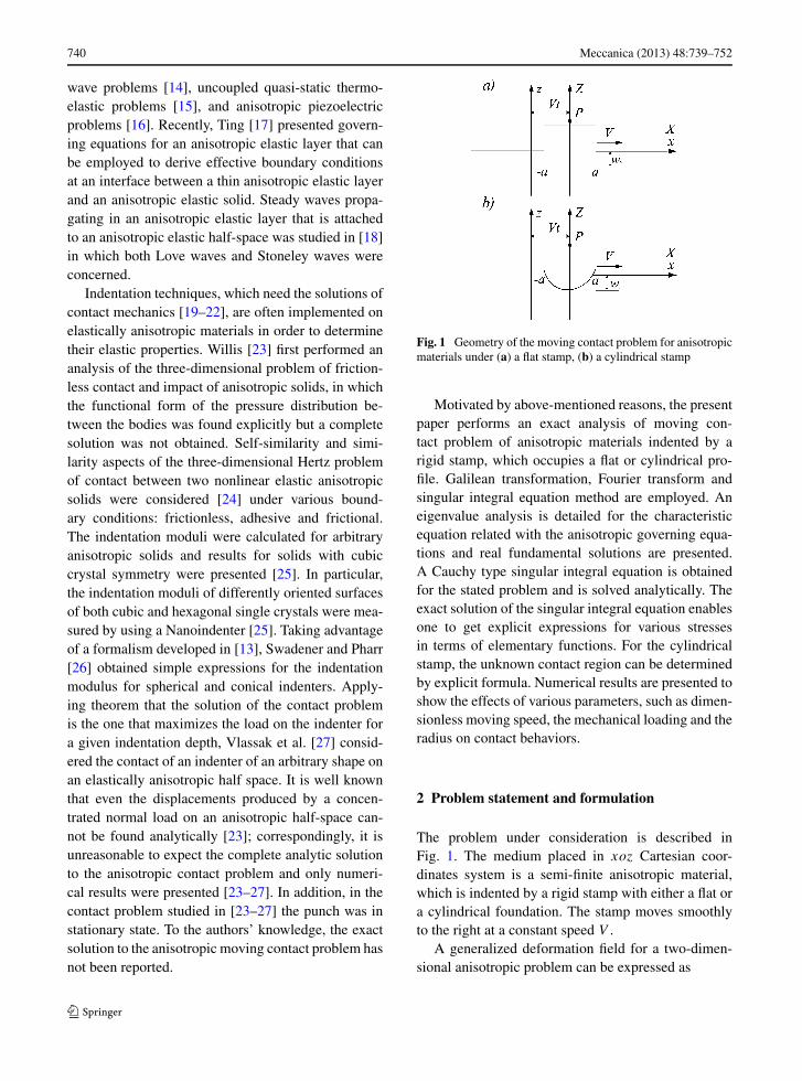
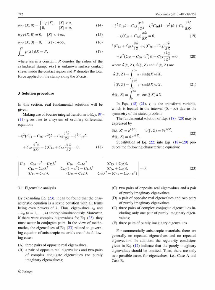
Fig. 1 Geometry of the moving contact problem for anisotropicmaterials under (a) a flat stamp, (b) a cylindrical stamp
Motivated by above-mentioned reasons, the presentpaper performs an exact analysis of moving con-tact problem of anisotropic materials indented by arigid stamp, which occupies a flat or cylindrical pro-file. Galilean transformation, Fourier transform andsingular integral equation method are employed. Aneigenvalue analysis is detailed for the characteristicequation related with the anisotropic governing equa-tions and real fundamental solutions are presented.A Cauchy type singular integral equation is obtainedfor the stated problem and is solved analytically. Theexact solution of the singular integral equation enablesone to get explicit expressions for various stressesin terms of elementary functions. For the cylindricalstamp, the unknown contact region can be determinedby explicit formula. Numerical results are presented toshow the effects of various parameters, such as dimen-sionless moving speed, the mechanical loading and theradius on contact behaviors.
2 Problem statement and formulation
The problem under consideration is described inFig. 1. The medium placed in xoz Cartesian coor-dinates system is a semi-finite anisotropic material,which is indented by a rigid stamp with either a flat ora cylindrical foundation. The stamp moves smoothlyto the right at a constant speed V .
A generalized deformation field for a two-dimen-sional anisotropic problem can be expressed as
Meccanica (2013) 48:739–752 741
u = u(x, z, t),
v = v(x, z, t),
w = w(x, z, t),
(1)
where t denotes time.The constitutive equations for two-dimensional
anisotropic materials can be written as⎡⎢⎢⎢⎢⎣
σxx
σzz
σyz
σxz
σxy
⎤⎥⎥⎥⎥⎦
=
⎡⎢⎢⎢⎢⎣
C11 C13 0 0 2C16
C13 C33 0 0 2C36
0 0 2C44 2C45 00 0 2C45 2C55 0
C16 C36 0 0 2C66
⎤⎥⎥⎥⎥⎦
·
⎡⎢⎢⎢⎢⎣
Sxx
Szz
Syz
Sxz
Sxy
⎤⎥⎥⎥⎥⎦
(2)
where σij stand for the components of the stress, Ckl
are the elastic coefficients and the strain Smn are givenby
Smn = 1
2
(∂um
∂xn
+ ∂un
∂xm
). (3)
Here for convince, um (m = x, y, z) denote, respec-tively, u, v and w.
Equilibrium equations of free body force are givenas follows:
∂σxx
∂x+ ∂σxz
∂z= ρ
∂2u
∂t2,
∂σxy
∂x+ ∂σyz
∂z= ρ
∂2v
∂t2,
∂σxz
∂x+ ∂σzz
∂z= ρ
∂2w
∂t2,
(4)
where ρ represents mass density.Substitution of the constitution equation (2) into
Eq. (4) produces governing equations for anisotropicmaterials as follows:
C11∂2u
∂x2+ C55
∂2u
∂z2+ C16
∂2v
∂x2+ C45
∂2v
∂z2
+ (C13 + C55)∂2w
∂x∂z= ρ
∂2u
∂t2, (5)
C16∂2u
∂x2+ C45
∂2u
∂z2+ C66
∂2v
∂x2+ C44
∂2v
∂z2
+ (C36 + C45)∂2w
∂x∂z= ρ
∂2v
∂t2, (6)
(C13 + C55)∂2u
∂x∂z+ (C36 + C45)
∂2v
∂x∂z+ C55
∂2w
∂x2
+ C33∂2w
∂z2= ρ
∂2w
∂t2. (7)
To make the present time related problem tractable,Galilean transformation is introduced
x = X + V t, y = Y, z = Z (8)
with (X,Y,Z) being a translating coordinate system,which is attached to the stamp. Since the stamp movessmoothly as mentioned above, it is assumed that themoving of the stamp has prevailed for such a long timethat there are local deformations only inside the con-tact region as given in Eq. (13) later and no local defor-mations outside the contact region. In the coordinatesystem (X,Y,Z), the problem is in the steady state,and can be treated symmetrically.
Taking into account Eq. (8), one can rewrite Eqs. (5)–(7) as follows:
(C11 − C66 · c2) ∂2u
∂X2+ C55
∂2u
∂Z2+ C16
∂2v
∂X2
+ C45∂2v
∂Z2+ (C13 + C55)
∂2w
∂X∂Z= 0, (9)
C16∂2u
∂X2+ C45
∂2u
∂Z2+ C66
(1 − c2) ∂2v
∂X2+ C44
∂2v
∂Z2
+ (C36 + C45)∂2w
∂X∂Z= 0, (10)
(C13 + C55)∂2u
∂X∂Z+ (C36 + C45)
∂2v
∂X∂Z
+ (C55 − C66 · c2)∂2w
∂X2+ C33
∂2w
∂Z2= 0, (11)
which govern the steady state solution of the problem.Here c = V
cBis the relative punch moving velocity and
cB =√
c66ρ
is the lowest Bulk wave velocity.
To solve partial differential equations (9)–(11),boundary conditions should be equipped. At infinity,the following conditions should be satisfied:
u(X,Z), v(X,Z),w(X,Z) → 0,√X2 + Z2 → ∞.
(12)
At the interface Z = 0, one has
w(X,0) ={
−w0, Flat stamp,
−w0 + X2
2R, Cylindrical stamp,
|X| < a, (13)
742 Meccanica (2013) 48:739–752
σZZ(X,0) ={−p(X), |X| < a,
0, |X| > a,(14)
σXZ(X,0) = 0, |X| < +∞, (15)
σYZ(X,0) = 0, |X| < +∞, (16)∫ a
−a
p(X)dX = P, (17)
where w0 is a constant, R denotes the radius of thecylindrical stamp, p(x) is unknown surface contactstress inside the contact region and P denotes the totalforce applied on the stamp along the Z-axis.
3 Solution procedure
In this section, real fundamental solutions will begiven.
Making use of Fourier integral transform to Eqs. (9)–(11) gives rise to a system of ordinary differentialequations
−ξ2(C11 − C66 · c2)u + C55∂2u
Z2− ξ2C16v
+ C45∂2v
∂Z2− ξ(C13 + C55)
∂w
∂Z= 0, (18)
−ξ2C16u + C45∂2u
∂Z2− ξ2C66
(1 − c2)v + C44
∂2v
∂Z2
− ξ(C36 + C45)∂w
∂Z= 0, (19)
ξ(C13 + C55)∂u
∂Z+ ξ(C36 + C45)
∂v
∂Z
− ξ2(C55 − C66 · c2)w + C33∂2w
∂Z2= 0, (20)
where u(ξ,Z), v(ξ,Z) and w(ξ,Z) are
u(ξ,Z) =∫ ∞
0u · sin(ξX)dX,
v(ξ,Z) =∫ ∞
0v · sin(ξX)dX,
w(ξ,Z) =∫ ∞
0w · cos(ξX)dX.
(21)
In Eqs. (18)–(21), ξ is the transform variable,which is located in the interval (0,+∞) due to thesymmetry of the stated problem.
The fundamental solution of Eqs. (18)–(20) may beexpressed by
u(ξ,Z) = eλξZ, v(ξ,Z) = θeλξZ,
w(ξ,Z) = ϑeλξZ.(22)
Substitution of Eq. (22) into Eqs. (18)–(20) pro-duces the following characteristic equation:
∣∣∣∣∣∣C11 − C66 · c2 − C55λ
2 C16 − C45λ2 (C13 + C55)λ
C16 − C45λ2 C66(1 − c2) − C44λ
2 (C36 + C45)λ
(C13 + C55)λ (C36 + C45)λ C33λ2 − (C55 − C66 · c2)
∣∣∣∣∣∣= 0. (23)
3.1 Eigenvalue analysis
By expanding Eq. (23), it can be found that the char-acteristic equation is a sextic equation with all termsbeing even powers of λ. Thus, eigenvalues λn and−λn (n = 1, . . . ,4) emerge simultaneously. Moreover,if there were complex eigenvalues for Eq. (23), theymust occur in conjugate pairs. In the view of mathe-matics, the eigenvalues of Eq. (23) related to govern-ing equation of anisotropic materials are of the follow-ing cases:
(A) three pairs of opposite real eigenvalues;(B) a pair of opposite real eigenvalues and two pairs
of complex conjugate eigenvalues (no purelyimaginary eigenvalues);
(C) two pairs of opposite real eigenvalues and a pairof purely imaginary eigenvalues;
(D) a pair of opposite real eigenvalues and two pairsof purely imaginary eigenvalues;
(E) three pairs of complex conjugate eigenvalues in-cluding only one pair of purely imaginary eigen-values;
(F) three pairs of purely imaginary eigenvalues.
For commercially anisotropic materials, there aregenerally no repeated eigenvalues and no repeatedeigenvectors. In addition, the regularity conditionsgiven in Eq. (12) indicate that the purely imaginaryeigenvalues should be omitted. Then, there are onlytwo possible cases for eigenvalues, i.e., Case A andCase B.
Meccanica (2013) 48:739–752 743
3.2 Real fundamental solutions
For the Case A, there are three pairs of opposite realroots
λ1 = −λ6 = α1, λ2 = −λ5 = α2,
λ3 = −λ4 = α3,(24)
where αj > 0 (j = 1, . . . ,3).Noting that real eigenvalue always yields real
eigenvector and considering the requirements at in-
finity given in Eq. (12), one can readily obtain realfundamental solutions Ωn = [Ω1n(ξ,Z) Ω2n(ξ,Z)
Ω3n(ξ,Z)]T (n = 1, . . . ,3) as
Ωn = eαnξZ[1 θ ϑ ]T= eαnξZ
[1 q1(αn) q2(αn)
]T, (25)
where the superscript T denotes transpose of a vector,q1(λn) and q2(λn) are
q1(λn) =∣∣∣∣−(C11 − C66 · c2 − C55λ
2n) (C13 + C55)λn
−(C16 − C45λ2n) (C36 + C45)λn
∣∣∣∣/∣∣∣∣
C16 − C45λ2n (C13 + C55)λn
C66(1 − c2) − C44λ2n (C36 + C45)λn
∣∣∣∣ ,
q2(λn) =∣∣∣∣
C16 − C45λ2n −(C11 − C66 · c2 − C55λ
2n)
C66(1 − c2) − C44λ2n −(C16 − C45λ
2n)
∣∣∣∣/∣∣∣∣
C16 − C45λ2n (C13 + C55)λn
C66(1 − c2) − C44λ2n (C36 + C45)λn
∣∣∣∣ .(26)
For the Case B, there are a pair of opposite realroots and two pairs of complex conjugate roots
λ1 = −λ6 = δ0, λ2 = −λ5 = δ + i · χ,
λ3 = −λ4 = δ − i · χ,(27)
where i2 = −1, δ0 > 0, δ > 0 and χ is a real num-ber. Complex eigenvalue produces complex eigenvec-tor. Since complex conjugate eigenvalues emerge si-multaneously, their corresponding eigenvectors occurin conjugate pairs. Thus, there are a pair of real eigen-vectors and two pairs of complex eigenvalues, whichhave the same forms given in Eq. (25) after replacingαj by λj . Since λ2 and λ3 are complex eigenvectors,the second and the third components of Eq. (25) arecomplex. With consideration of the following Euler’sformula:
ei·χξZ = cos(χξZ) + i · sin(χξZ), (28)
one can obtain the real fundamental solutions Ωj =[Ω1j (ξ,Z) Ω2j (ξ,Z) Ω3j (ξ,Z)]T (j = 1, . . . ,3)as
Ω1 = eδ0ξZ
⎡⎣
1q1(δ0)
q2(δ0)
⎤⎦ ,
Ω2 = eδξZ
⎡⎣
cos(χξZ)
Υ1 cos(χξZ) − T1 sin(χξZ)
Υ2 cos(χξZ) − T2 sin(χξZ)
⎤⎦ ,
Ω3 = eδξZ
⎡⎣
sin(χξZ)
T1 cos(χξZ) + Υ1 sin(χξZ)
T2 cos(χξZ) + Υ2 sin(χξZ)
⎤⎦ ,
(29)
where
Υj = Re[qj (λ2)
], Tj = Im
[qj (λ2)
],
(j = 1,2) (30)
Here, Re[ ] and Im[ ] denote, respectively, real partand imaginary part, and the functions qj ( ) are definedin Eq. (26).
3.3 General solution
The general solutions of Eqs. (18)–(20) may be givenin terms of real fundamental solutions
[u(ξ,Z) v(ξ,Z) w(ξ,Z)
]T
=3∑
n=1
AnΩn(ξ,Z)
=3∑
n=1
An
[Ω1n(ξ,Z) Ω2n(ξ,Z) Ω3n(ξ,Z)
]T,
(31)
where An (n = 1, . . . ,3) are unknown coefficientfunctions.
4 Contact analysis
Next, the general solution in Eq. (31) is used to ana-lyze the contact problem depicted in Fig. 1.
744 Meccanica (2013) 48:739–752
Employing inverse transform to Eq. (21) and thensubstituting Eq. (31) into it yield
u(X,Z) = 2
π
∫ ∞
0
3∑n=1
AnΩ1n(ξ,Z) sin(ξX)dξ,
v(X,Z) = 2
π
∫ ∞
0
3∑n=1
AnΩ2n(ξ,Z) sin(ξX)dξ,
w(X,Z) = 2
π
∫ ∞
0
3∑n=1
AnΩ3n(ξ,Z) cos(ξX)dξ.
(32)
Substitution of Eq. (32) into Eq. (2) in view ofGalilean transformation given in Eq. (8) leads to
σXX = 2
π
∫ ∞
0
3∑n=1
ξ · �0n(ξ,Z) · An · cos(ξX)dξ,
σZZ = 2
π
∫ ∞
0
3∑n=1
ξ · �1n(ξ,Z) · An · cos(ξX)dξ,
σXZ = 2
π
∫ ∞
0
3∑n=1
ξ · �2n(ξ,Z) · An · sin(ξX)dξ,
σYZ = 2
π
∫ ∞
0
3∑n=1
ξ · �3n(ξ,Z) · An · sin(ξX)dξ,
(33)
where known functions �mn(ξ,Z) (m = 0, . . . ,3, n =1, . . . ,3) are given in Appendix.
Substituting the second, the third and the fourthequation of Eq. (33) into Eqs. (14)–(16) and employ-ing inverse transformation yield
3∑n=1
ξ · �1n(ξ,0) · An = −F0,
3∑n=1
ξ · �2n(ξ,0) · An = 0,
3∑n=1
ξ · �3n(ξ,0) · An = 0,
(34)
where
F0 =∫ a
0p(ω) cos(ξω)dω. (35)
Solving Eq. (34) arrives at
An = (−1)n
ξ · Π Π1nF0 (n = 1, . . . ,3), (36)
where Π is the determinant and Πmn (m,n = 1, . . . ,3)are complement minors of a matrix Πcoe given inAppendix.
Substituting Eq. (36) into Eq. (32) and then differ-entiating the third equation of Eq. (32) give rise to
∂w(X,0)
∂X= 1
π
∫ a
−a
∫ ∞
0K0(X,ω)p(ω) cos(ξω)
· sin(ξX)dξ dω, (37)
where the kernel K0(X,ω) is given as
K0 =3∑
n=1
(−1)n+1Ω3n(ξ,0)Π1n
Π. (38)
It can be checked that K0 is independent on ξ .Thus, Eq. (37) can be rewritten into the following sin-gular integral equation:
1
π
∫ a
−a
K0
ω − Xp(ω)dω = −∂w0(X)
∂X. (39)
In addition, to make the stated problem complete,one should consider the equilibrium equation (17).
In the following, exact solution of integral equa-tions (39) and (17) will be given in cases of a flat and acylindrical stamp profile. Then explicit expressions ofvarious stresses will be presented.
5 Exact solutions for a flat stamp
In this case, differentiating the first equation of Eq. (13)yields
∂w0(X)
∂X= 0. (40)
Thus, the exact solution of integral Eqs. (39)and (17) [28] takes the form
p(X) = P
π√
a2 − X2, |X| < a. (41)
The stress intensity factor at the end of the flatstamp may be defined as follows:
KI = limX→a−
√2π(a − X)σZZ(X,0). (42)
In view of Eq. (41), Eq. (42) can be simplified asfollows:
KI = −√
1
πaP. (43)
Substituting Eq. (41) into Eq. (36) yields the fol-lowing expression for An (n = 1, . . . ,3):
An = (−1)nΠ1n
2ξ · Π P · J0(ξ · a), (44)
Meccanica (2013) 48:739–752 745
where J0(·) is the 0-order Bessel function of the firstkind.
Substituting Eq. (44) into Eq. (33), one can obtainthe following explicit expressions of various stresses:
⎡⎢⎢⎣
σXX
σZZ
σXZ
σYZ
⎤⎥⎥⎦ = P
π · Π3∑
n=1
(−1)nΠ1n
⎡⎢⎢⎢⎢⎢⎣
Λ(f )
0n (X,Z)
Λ(f )
1n (X,Z)
Λ(f )
2n (X,Z)
Λ(f )
3n (X,Z)
⎤⎥⎥⎥⎥⎥⎦
,
(45)
where known functions Λ(f )mn (X,Z) (m = 0,1,2,3,
n = 1,2,3) are given in Appendix.
6 Exact solutions for a cylindrical stamp
In this case, differentiating the second equation ofEq. (13) leads to
∂w0(X)
∂X= X
R. (46)
The exact solution of the singular integral equa-tion (39) [28] is obtained as
p(X) =√
a2 − X2
K0 · R , |X| < a. (47)
Substituting Eq. (47) into equilibrium condition(17) arrives at the following relationship between thehalf-width a of the contact region and the indentationload P :
a =√
2P · K0 · Rπ
. (48)
Inserting Eq. (47) into Eq. (35), one can simplifyEq. (36) as follows:
An = (−1)na · π · Π1n
2ξ2 · K0 · R · Π J1(ξ · a),
(n = 1, . . . ,3), (49)
where J1(·) is the 1-order Bessel function of the firstkind.
Substituting Eq. (49) into Eq. (33), one can obtainthe following explicit expressions to determine variousstresses:
⎡⎢⎢⎣
σXX
σZZ
σXZ
σYZ
⎤⎥⎥⎦ = a
Π · K0 · R3∑
n=1
(−1)nΠ1n
⎡⎢⎢⎢⎢⎣
Λ(c)0n (X,Z)
Λ(c)1n (X,Z)
Λ(c)2n (X,Z)
Λ(c)3n (X,Z)
⎤⎥⎥⎥⎥⎦
,
(50)
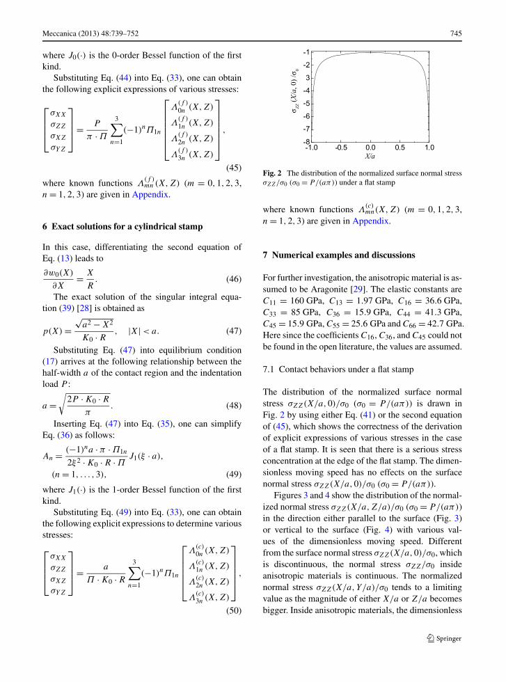
Fig. 2 The distribution of the normalized surface normal stressσZZ/σ0 (σ0 = P/(aπ)) under a flat stamp
where known functions Λ(c)mn(X,Z) (m = 0,1,2,3,
n = 1,2,3) are given in Appendix.
7 Numerical examples and discussions
For further investigation, the anisotropic material is as-sumed to be Aragonite [29]. The elastic constants areC11 = 160 GPa, C13 = 1.97 GPa, C16 = 36.6 GPa,C33 = 85 GPa, C36 = 15.9 GPa, C44 = 41.3 GPa,C45 = 15.9 GPa, C55 = 25.6 GPa and C66 = 42.7 GPa.Here since the coefficients C16, C36, and C45 could notbe found in the open literature, the values are assumed.
7.1 Contact behaviors under a flat stamp
The distribution of the normalized surface normalstress σZZ(X/a,0)/σ0 (σ0 = P/(aπ)) is drawn inFig. 2 by using either Eq. (41) or the second equationof (45), which shows the correctness of the derivationof explicit expressions of various stresses in the caseof a flat stamp. It is seen that there is a serious stressconcentration at the edge of the flat stamp. The dimen-sionless moving speed has no effects on the surfacenormal stress σZZ(X/a,0)/σ0 (σ0 = P/(aπ)).
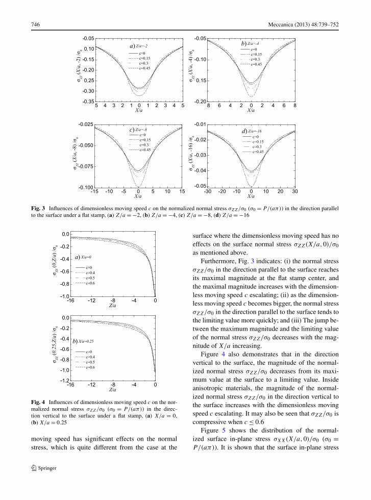
Figures 3 and 4 show the distribution of the normal-ized normal stress σZZ(X/a,Z/a)/σ0 (σ0 = P/(aπ))in the direction either parallel to the surface (Fig. 3)or vertical to the surface (Fig. 4) with various val-ues of the dimensionless moving speed. Differentfrom the surface normal stress σZZ(X/a,0)/σ0, whichis discontinuous, the normal stress σZZ/σ0 insideanisotropic materials is continuous. The normalizednormal stress σZZ(X/a,Y/a)/σ0 tends to a limitingvalue as the magnitude of either X/a or Z/a becomesbigger. Inside anisotropic materials, the dimensionless
746 Meccanica (2013) 48:739–752
Fig. 3 Influences of dimensionless moving speed c on the normalized normal stress σZZ/σ0 (σ0 = P/(aπ)) in the direction parallelto the surface under a flat stamp, (a) Z/a = −2, (b) Z/a = −4, (c) Z/a = −8, (d) Z/a = −16
Fig. 4 Influences of dimensionless moving speed c on the nor-malized normal stress σZZ/σ0 (σ0 = P/(aπ)) in the direc-tion vertical to the surface under a flat stamp, (a) X/a = 0,(b) X/a = 0.25
moving speed has significant effects on the normalstress, which is quite different from the case at the
surface where the dimensionless moving speed has noeffects on the surface normal stress σZZ(X/a,0)/σ0
as mentioned above.Furthermore, Fig. 3 indicates: (i) the normal stress
σZZ/σ0 in the direction parallel to the surface reachesits maximal magnitude at the flat stamp center, andthe maximal magnitude increases with the dimension-less moving speed c escalating; (ii) as the dimension-less moving speed c becomes bigger, the normal stressσZZ/σ0 in the direction parallel to the surface tends tothe limiting value more quickly; and (iii) The jump be-tween the maximum magnitude and the limiting valueof the normal stress σZZ/σ0 decreases with the mag-nitude of X/a increasing.
Figure 4 also demonstrates that in the directionvertical to the surface, the magnitude of the normal-ized normal stress σZZ/σ0 decreases from its maxi-mum value at the surface to a limiting value. Insideanisotropic materials, the magnitude of the normal-ized normal stress σZZ/σ0 in the direction vertical tothe surface increases with the dimensionless movingspeed c escalating. It may also be seen that σZZ/σ0 iscompressive when c ≤ 0.6
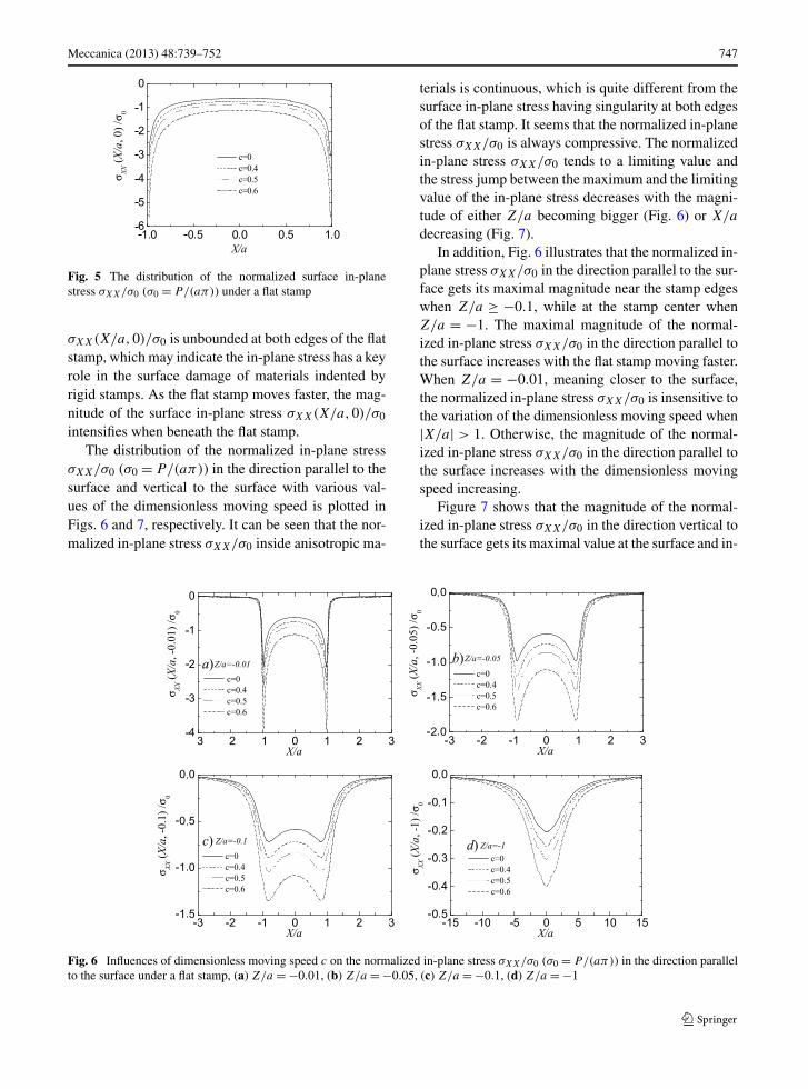
Figure 5 shows the distribution of the normal-ized surface in-plane stress σXX(X/a,0)/σ0 (σ0 =P/(aπ)). It is shown that the surface in-plane stress
Meccanica (2013) 48:739–752 747
Fig. 5 The distribution of the normalized surface in-planestress σXX/σ0 (σ0 = P/(aπ)) under a flat stamp
σXX(X/a,0)/σ0 is unbounded at both edges of the flatstamp, which may indicate the in-plane stress has a keyrole in the surface damage of materials indented byrigid stamps. As the flat stamp moves faster, the mag-nitude of the surface in-plane stress σXX(X/a,0)/σ0
intensifies when beneath the flat stamp.The distribution of the normalized in-plane stress
σXX/σ0 (σ0 = P/(aπ)) in the direction parallel to thesurface and vertical to the surface with various val-ues of the dimensionless moving speed is plotted inFigs. 6 and 7, respectively. It can be seen that the nor-malized in-plane stress σXX/σ0 inside anisotropic ma-
terials is continuous, which is quite different from thesurface in-plane stress having singularity at both edgesof the flat stamp. It seems that the normalized in-planestress σXX/σ0 is always compressive. The normalizedin-plane stress σXX/σ0 tends to a limiting value andthe stress jump between the maximum and the limitingvalue of the in-plane stress decreases with the magni-tude of either Z/a becoming bigger (Fig. 6) or X/a
decreasing (Fig. 7).In addition, Fig. 6 illustrates that the normalized in-
plane stress σXX/σ0 in the direction parallel to the sur-face gets its maximal magnitude near the stamp edgeswhen Z/a ≥ −0.1, while at the stamp center whenZ/a = −1. The maximal magnitude of the normal-ized in-plane stress σXX/σ0 in the direction parallel tothe surface increases with the flat stamp moving faster.When Z/a = −0.01, meaning closer to the surface,the normalized in-plane stress σXX/σ0 is insensitive tothe variation of the dimensionless moving speed when|X/a| > 1. Otherwise, the magnitude of the normal-ized in-plane stress σXX/σ0 in the direction parallel tothe surface increases with the dimensionless movingspeed increasing.
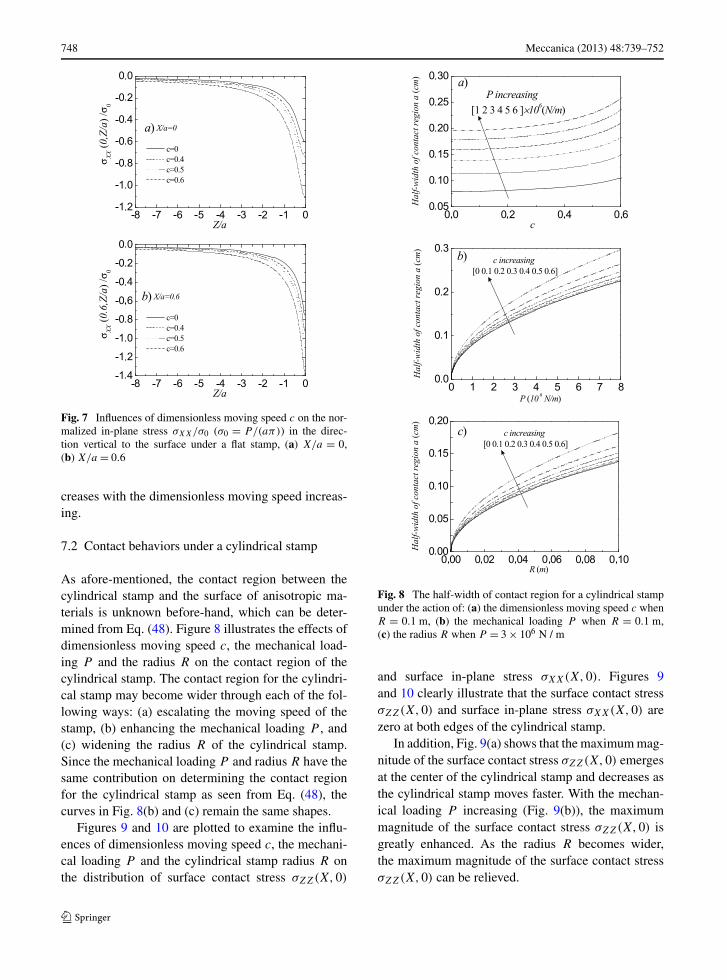
Figure 7 shows that the magnitude of the normal-ized in-plane stress σXX/σ0 in the direction vertical tothe surface gets its maximal value at the surface and in-
Fig. 6 Influences of dimensionless moving speed c on the normalized in-plane stress σXX/σ0 (σ0 = P/(aπ)) in the direction parallelto the surface under a flat stamp, (a) Z/a = −0.01, (b) Z/a = −0.05, (c) Z/a = −0.1, (d) Z/a = −1
748 Meccanica (2013) 48:739–752
Fig. 7 Influences of dimensionless moving speed c on the nor-malized in-plane stress σXX/σ0 (σ0 = P/(aπ)) in the direc-tion vertical to the surface under a flat stamp, (a) X/a = 0,(b) X/a = 0.6
creases with the dimensionless moving speed increas-ing.
7.2 Contact behaviors under a cylindrical stamp
As afore-mentioned, the contact region between thecylindrical stamp and the surface of anisotropic ma-terials is unknown before-hand, which can be deter-mined from Eq. (48). Figure 8 illustrates the effects ofdimensionless moving speed c, the mechanical load-ing P and the radius R on the contact region of thecylindrical stamp. The contact region for the cylindri-cal stamp may become wider through each of the fol-lowing ways: (a) escalating the moving speed of thestamp, (b) enhancing the mechanical loading P , and(c) widening the radius R of the cylindrical stamp.Since the mechanical loading P and radius R have thesame contribution on determining the contact regionfor the cylindrical stamp as seen from Eq. (48), thecurves in Fig. 8(b) and (c) remain the same shapes.
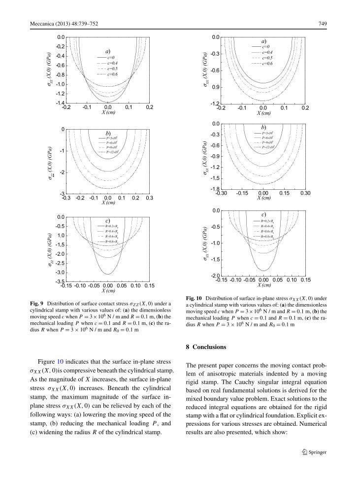
Figures 9 and 10 are plotted to examine the influ-ences of dimensionless moving speed c, the mechani-cal loading P and the cylindrical stamp radius R onthe distribution of surface contact stress σZZ(X,0)
Fig. 8 The half-width of contact region for a cylindrical stampunder the action of: (a) the dimensionless moving speed c whenR = 0.1 m, (b) the mechanical loading P when R = 0.1 m,(c) the radius R when P = 3 × 10⁶ N / m
and surface in-plane stress σXX(X,0). Figures 9and 10 clearly illustrate that the surface contact stressσZZ(X,0) and surface in-plane stress σXX(X,0) arezero at both edges of the cylindrical stamp.
In addition, Fig. 9(a) shows that the maximum mag-nitude of the surface contact stress σZZ(X,0) emergesat the center of the cylindrical stamp and decreases asthe cylindrical stamp moves faster. With the mechan-ical loading P increasing (Fig. 9(b)), the maximummagnitude of the surface contact stress σZZ(X,0) isgreatly enhanced. As the radius R becomes wider,the maximum magnitude of the surface contact stressσZZ(X,0) can be relieved.
Meccanica (2013) 48:739–752 749
Fig. 9 Distribution of surface contact stress σZZ(X,0) under acylindrical stamp with various values of: (a) the dimensionlessmoving speed c when P = 3×10⁶ N / m and R = 0.1 m, (b) themechanical loading P when c = 0.1 and R = 0.1 m, (c) the ra-dius R when P = 3 × 10⁶ N / m and R0 = 0.1 m
Figure 10 indicates that the surface in-plane stressσXX(X,0)is compressive beneath the cylindrical stamp.As the magnitude of X increases, the surface in-planestress σXX(X,0) increases. Beneath the cylindricalstamp, the maximum magnitude of the surface in-plane stress σXX(X,0) can be relieved by each of thefollowing ways: (a) lowering the moving speed of thestamp, (b) reducing the mechanical loading P , and(c) widening the radius R of the cylindrical stamp.
Fig. 10 Distribution of surface in-plane stress σXX(X,0) undera cylindrical stamp with various values of: (a) the dimensionlessmoving speed c when P = 3×10⁶ N / m and R = 0.1 m, (b) themechanical loading P when c = 0.1 and R = 0.1 m, (c) the ra-dius R when P = 3 × 10⁶ N / m and R0 = 0.1 m
8 Conclusions
The present paper concerns the moving contact prob-lem of anisotropic materials indented by a movingrigid stamp. The Cauchy singular integral equationbased on real fundamental solutions is derived for themixed boundary value problem. Exact solutions to thereduced integral equations are obtained for the rigidstamp with a flat or cylindrical foundation. Explicit ex-pressions for various stresses are obtained. Numericalresults are also presented, which show:
750 Meccanica (2013) 48:739–752
1. For the flat stamp, the dimensionless moving speedhas no effects on the surface normal stress, whilegreatly affects the distribution of surface in-planestress beneath the flat stamp.
2. The surface in-plane stress is unbounded at bothedges of the flat stamp.
3. The dimensionless moving speed has a significanteffect on the distribution of the normal and in-planestresses inside anisotropic materials indented by aflat stamp.
4. The contact region for the cylindrical stamp canbecome wider through each of the following ways:(a) escalating the moving speed of the stamp,(b) enhancing the mechanical loading P , and(c) widening the radius R of the cylindrical stamp.
5. The surface contact stress and surface in-planestress are zero at both edges of the cylindricalstamp.
6. With the mechanical loading P increasing, themaximum magnitude of the surface contact stressand surface in-plane stress beneath the cylindricalstamp are greatly enhanced.
Acknowledgements The authors would like to thank theanonymous reviewers for their helpful suggestions to improvethis paper. This work was supported by the National Natu-ral Science Foundation of China (10962008, 51061015 and61063020).
Appendix
1. Expressions of �mn(ξ,Z) (m = 0, . . . ,3, n =1, . . . ,3) appearing in Eq. (33)
For Case A
�mn(ξ,Z) = ΘmneξαnZ, (A.1)
where Θmn (m = 0, . . . ,3, n = 1, . . . ,3) are given asfollows:
Θ0n = C11 + C16q1(αn) + C13αnq2(αn),
n = 1, . . . ,3, (A.2)
Θ1n = C13 + C36q1(αn) + C33αnq2(αn),
n = 1, . . . ,3, (A.3)
Θ2n = C55[αn − q2(αn)
] + C45αnq1(αn),
n = 1, . . . ,3, (A.4)
Θ3n = C45[αn − q2(αn)
] + C44αnq1(αn),
n = 1, . . . ,3. (A.5)
For Case B
�m1(ξ,Z) = Θm1eδ0ξZ, m = 0, . . .3, (A.6)
�m2(ξ,Z)
= [Θ
(C)m2 cos(χξZ) − Θ
(S)m2 sin(χξZ)
]eδξZ,
m = 0, . . . ,3, (A.7)
�m3(ξ,Z)
= [Θ
(S)m2 cos(χξZ) + Θ
(C)m2 sin(χξZ)
]eδξZ,
m = 0, . . . ,3, (A.8)
where Θm1 are the same as those given in Eq. (A.2)with α1 replaced by δ0, Θ
(C)m2 and Θ
(S)m2 are given as
Θ(C)02 = C11 + C16Υ1 + C13(δ · Υ2 − χ · T2),
Θ(S)02 = C16T1 + C13(δ · T2 + χ · Υ2),
(A.9)
Θ(C)12 = C13 + C36Υ1 + C33(δ · Υ2 − χ · T2),
Θ(S)12 = C36T1 + C33(δ · T2 + χ · Υ2),
(A.10)
Θ(C)22 = C55(δ − Υ2) + C45(δ · Υ1 − χ · T1),
Θ(S)22 = C55(χ − T2) + C45(χ · Υ1 + δ · T1),
(A.11)
Θ(C)32 = C45(δ − Υ2) + C44(δ · Υ1 − χ · T1),
Θ(S)32 = C45(χ − T2) + C44(χ · Υ1 + δ · T1).
(A.12)
2. Matrix Πcoe appearing in Eq. (36)
Πcoe =⎡⎣
�11(ξ,0) �12(ξ,0) �13(ξ,0)
�21(ξ,0) �22(ξ,0) �23(ξ,0)
�31(ξ,0) �32(ξ,0) �33(ξ,0)
⎤⎦ .
(A.13)
3. Known functions Λ(f )mn (X,Z) (m = 0,1,2,3, n =
1,2,3) appearing in Eq. (45)For Case A
Λ(f )mn (X,Z) = Θmn ·
{Γ
(f )
1n (X,Z), m = 0,1,
Γ(f )
2n (X,Z), m = 2,3,
(A.14)
where
Γ(f )
1n (X,Z) =√
τ 22n − X2
τ 22n − τ 2
1n
,
Γ(f )
2n (X,Z) = sgn(X)
√X2 − τ 2
1n
τ 22n − τ 2
1n
,
(A.15)
Meccanica (2013) 48:739–752 751
τ1n = 1
2
(√(X + a)2 + (αnZ)2
−√
(X − a)2 + (αnZ)2),
τ2n = 1
2
(√(X + a)2 + (αnZ)2
+√
(X − a)2 + (αnZ)2).
(A.16)
where sgn(·) is the sign function.For Case B
Λ(f )
m1 (X,Z) = Θm1 ·{
Γ(f )
11 (X,Z), m = 0,1,
Γ(f )
21 (X,Z), m = 2,3,
(A.17)
Λ(f )
m2 (X,Z)
= 1
2
⎧⎪⎪⎪⎨⎪⎪⎪⎩
Θ(C)m2 �
(f )
11 (X,Z) − Θ(S)m2 �
(f )
12 (X,Z),
m = 0,1,
Θ(C)m2 �
(f )
21 (X,Z) − Θ(S)m2 �
(f )
22 (X,Z),
m = 2,3,
(A.18)
Λ(f )
m3 (X,Z)
= 1
2
⎧⎪⎪⎪⎨⎪⎪⎪⎩
Θ(S)m2 �
(f )
11 (X,Z) + Θ(C)m2 �
(f )
12 (X,Z),
m = 0,1,
Θ(S)m2 �
(f )
21 (X,Z) + Θ(C)m2 �
(f )
22 (X,Z),
m = 2,3,
(A.19)
where Γ(f )
n1 (X,Z) (n = 1,2) are the same as those in
Eq. (A.15) with α1 replaced by δ0, and �(f )kl (X,Z)
(k, l = 1,2) are given as follows:
�(f )
1n (X,Z) = M(f )
n1 (X,Z) + M(f )
n2 (X,Z)
(n = 1,2),
�(f )
21 (X,Z) = M(f )
21 (X,Z) − M(f )
22 (X,Z),
�(f )
22 (X,Z) = −M(f )
11 (X,Z) + M(f )
12 (X,Z),
(A.20)
M(f )
1n (X,Z) =√
ς2n2 − X2
n
ς2n2 − ς2
n1
, n = 1,2,
M(f )
2n (X,Z) = sgn(Xn)
√X2
n − ς2n1
ς2n2 − ς2
n1
, n = 1,2,
(A.21)
with
ς11 = 1
2
(√(X1 + a)2 + (δZ)2
−√
(X1 − a)2 + (δZ)2), (A.22)
ς12 = 1
2
(√(X1 + a)2 + (δZ)2
+√
(X1 − a)2 + (δZ)2), (A.23)
ς21 = 1
2
(√(X2 + a)2 + (δZ)2
−√
(X2 − a)2 + (δZ)2), (A.24)
ς22 = 1
2
(√(X2 + a)2 + (δZ)2
+√
(X2 − a)2 + (δZ)2), (A.25)
X1 = χ · Z + X, X2 = χ · Z − X. (A.26)
4. Known functions Λ(c)mn(X,Z) (m = 0,1,2,3, n =
1,2,3) appearing in Eq. (50)For Case A
Λ(c)mn(X,Z) = Θmn ·
{Γ
(c)1n (X,Z), m = 0,1,
Γ(c)
2n (X,Z), m = 2,3,
(A.27)
where
Γ(c)
1n (X,Z) =√
τ 22n − X2 + αnZ
a,
Γ(c)
2n (X,Z) =X − sgn(X)
√X2 − τ 2
1n
a,
(A.28)
where τ1n and τ2n (n = 1,2,3) are given in Eq. (A.16).For Case B
Λ(c)m1(X,Z)
= Θm1 ·{
Γ(c)
11 (X,Z), m = 0,1,
Γ(c)
21 (X,Z), m = 2,3,(A.29)
Λ(c)m2(X,Z)
= 1
2
⎧⎪⎪⎪⎨⎪⎪⎪⎩
Θ(C)m2 �
(c)11 (X,Z) − Θ
(S)m2 �
(c)12 (X,Z),
m = 0,1,
Θ(C)m2 �
(c)21 (X,Z) − Θ
(S)m2 �
(c)22 (X,Z),
m = 2,3,
(A.30)
Λ(c)m3(X,Z)
= 1
2
⎧⎪⎪⎪⎨⎪⎪⎪⎩
Θ(S)m2 �
(c)11 (X,Z) + Θ
(C)m2 �
(c)12 (X,Z),
m = 0,1,
Θ(S)m2 �
(c)21 (X,Z) + Θ
(C)m2 �
(c)22 (X,Z),
m = 2,3,
(A.31)
752 Meccanica (2013) 48:739–752
where Γ(c)n1 (X,Z) (n = 1,2) are the same as those in
Eq. (A.15) with α1 replaced by δ0, and �(c)kl (X,Z)
(k, l = 1,2) are given as follows:
�(c)1n (X,Z) = M(c)
n1 (X,Z) + M(c)n2 (X,Z) (n = 1,2),
�(c)21 (X,Z) = M(c)
21 (X,Z) − M(c)22 (X,Z),
�(c)22 (X,Z) = −M(c)
11 (X,Z) + M(c)12 (X,Z),
(A.32)
M(c)1n (X,Z) =
√ς2
n2 − X2n + δZ
a, n = 1,2,
M(c)2n (X,Z) =
Xn − sgn(Xn)
√X2
n − ς2n1
a, n = 1,2,
(A.33)
where ςkl (k, l = 1,2) and Xk (k = 1,2) are given,respectively, in Eqs. (A.22)–(A.26).
References
1. Banks-Sills L, Hershkovitz I, Wawrzynek PA, Eliasi R, In-graffea AR (2005) Methods for calculating stress intensityfactors in anisotropic materials: Part I—z = 0 is a symmet-ric plane. Eng Fract Mech 72:2328–2358
2. Sih GC, Irwin GR (1965) On cracks in rectilinearanisotropic bodies. Int J Fract Mech 1:189–302
3. Clements DL (1971) A crack between dissimilaranisotropic media. Int J Eng Sci 9:257–265
4. Kuo MC, Bogy DB (1974) Plane solutions for the displace-ment and traction displacement problems for anisotropicelastic wedges. J Appl Mech 41:197–203
5. Hoenig A (1982) Near-tip behavior of a crack in a planeanisotropic elastic body. Eng Fract Mech 16:393–403
6. Wang SS (1984) Edge delamination in angle-ply compositelaminates. AIAA J 22:256–264
7. Ting TCT, Hoang PH (1984) Singularities at the tip of acrack normal to the interface of an anisotropic layered com-posite. Int J Solids Struct 20:439–454
8. Lekhnitskii SG (1981) Theory of elasticity of an anisotropicbody. Mir, Moscow
9. Ting TCT (1986) Explicit solution and invariance of thesingularities at an interface crack in anisotropic composites.Int J Solids Struct 22:965–983
10. Eshelby JD, Read WT, Shockley W (1953) Anisotropicelasticity with applications to dislocations theory. ActaMetall 1:251–259
11. Stroh AN (1958) Dislocations and cracks in anisotropicelasticity. Philos Mag 3:625–646
12. Bamctt DM, Lothe J (1973) Synthesis of the sextic andthe integral formalism for dislocation, greens functionsand surface waves in anisotropic elastic solids. Phys Norv7:13–19
13. Bamctt DM, Lothe J (1975) Line force loadings onanisotropic half-space and wedges. Phys Norv 8:13–22
14. Chadwick P, Smith GD (1977) Foundations of the theoryof surface waves in anisotropic elastic materials. Adv ApplMech 17:303–376
15. Hwu C (1990) Thermal stresses in an anisotropic plate dis-turbed by an insulated elliptic hole or crack. ASME J ApplMech 57:916–922
16. Kuo CM, Barnett DM (1991) Stress singularities of interfa-cial cracks in bonded piezoelectric half-Spaces. In: Wu U,Ting TCT, Barnett DM (eds) Modern theory of anisotropicelasticity and application. SIAM, Philadelphia, pp 33–50
17. Ting TCT (2009) Mechanics of a thin anisotropic elasticlayer and a layer that is bonded to an anisotropic elasticbody or bodies. Proc R Soc A 463:2223–2239
18. Ting TCT (2009) Steady waves in an anisotropic elasticlayer attached to a half-space or between two half-spaces—a generalization of love waves and Stoneley waves. MathMech Solids 14:52–71
19. Carbone G, Bottiglione F (2011) Contact mechanics ofrough surfaces: a comparison between theories. Meccanica46:557–565
20. Fabrikant VI (2011) Contact problems for several trans-versely isotropic elastic layers on a smooth elastic half-space. Meccanica 46:1239–1263
21. Scarpetta E, Sumbatyan MA (2012) Some results on theenergy transmission through an elastic half-space loadedby a periodic distribution of vibrating punches. Meccanica47:369–378
22. Liu TJ, Wang YS, Xing YM (2012) The axisymmetric par-tial slip contact problem of a graded coating. Meccanica47:1673–1693
23. Willis JR (1966) Hertzian contact of anisotropic bodies.J Mech Phys Solids 14:163–176
24. Borodich FM (1993) The hertz frictional contact betweennonlinear elastic anisotropic bodies (the similarity ap-proach). Int J Solids Struct 30:1513–1526
25. Vlassak JJ, Nix WD (1994) Measuring the elastic proper-ties of anisotropic materials by means of indentation exper-iments. J Mech Phys Solids 42:1223–1245
26. Swadener JG, Pharr GM (2001) Indentation modulus ofelastically anistropic half-spaces by cones and parabolae ofrevolution. Philos Mag A 81:447–466
27. Vlassak JJ, Ciavarella M, Barber JR, Wang X (2003)The indentation modulus of elastically anisotropic mate-rials for indenters of arbitrary shape. J Mech Phys Solids51:1701–1721
28. Hills DA, Nowell D, Sackfield A (1993) Mechanics of elas-tic contacts. Butterworth-Heinemann, Oxford
29. Masaki N, Toru I, Noriyuki M (2007) Stress intensityfactor analysis of a three-dimensional interface crack be-tween dissimilar anisotropic materials. Eng Fract Mech74:2481–2497