Embed Size (px)
Citation preview
Utah State UniversityDigitalCommons@USU
All Graduate Theses and Dissertations Graduate Studies
5-2010
Effects of Temperature and Humidity on Glass-Reinforced Nylon Rotating BandsMarc D. RabyUtah State University
Follow this and additional works at: http://digitalcommons.usu.edu/etd
Part of the Mechanical Engineering Commons
This Thesis is brought to you for free and open access by the GraduateStudies at DigitalCommons@USU. It has been accepted for inclusion in AllGraduate Theses and Dissertations by an authorized administrator ofDigitalCommons@USU. For more information, please [email protected].
Recommended CitationRaby, Marc D., "Effects of Temperature and Humidity on Glass-Reinforced Nylon Rotating Bands" (2010). All Graduate Theses andDissertations. Paper 685.
EFFECTS OF TEMPERATURE AND HUMIDITY ON GLASS-REINFORCED
NYLON ROTATING BANDS
by
Marc D. Raby
A thesis submitted in partial fulfillment of the requirements for the degree
of
MASTER OF SCIENCE
in
Mechanical Engineering
Approved: _______________________________ Thomas H. Fronk Major Professor _______________________________ Barton L. Smith Committee Member
_______________________________ Steven L. Folkman Committee Member _______________________________ Byron R. Burnham Dean of Graduate Studies
UTAH STATE UNIVERSITY Logan, Utah
2010

ii
ABSTRACT
Effects of Temperature and Humidity on Glass-Reinforced
Nylon Rotating Bands
by
Marc D. Raby, Master of Science
Utah State University, 2010
Major Professor: Dr. Thomas H. Fronk Department: Mechanical and Aerospace Engineering
Certain 30mm munitions used in various military applications are configured with
a glass-reinforced nylon band that acts as a firing ring or rotating band. The purpose of
this research is to investigate whether storage environments compromise the strength and
integrity of the glass-reinforced nylon rotating bands by researching the environmental
factors that will degrade nylon and by performing tests to investigate if these factors will
embrittle nylon composites. Moisture and temperature are found to be the environmental
factors that will have an effect on the rotating bands in their respective storage
environments. Absorbed moisture is found to increase the impact strength of nylon while
at the same time expanding surface defects and attacking fiber/matrix bonds.
Two impact tests using a Tinius Olsen impact tester are used to determine the
effects of different storage environments on the impact strength of neat resin nylon 6/12
and 33% glass-reinforced nylon 6/12. The relative Shore D hardness of each reinforced
sample is also measured to determine if any correlation between impact strength and
iii
hardness exists. Absorbed moisture is found to increase the toughness of both neat resin
and reinforced nylon samples, but once dried again no significant difference in impact
strength is found.
A third test using a horizontal milling machine and a specially shaped tool is run
to try and recreate the deformation that the rotating band sees when impacting the rifling
of the gun. This test proved to be unsuccessful in generating brittle failure in glass-
reinforced test samples.
(67 pages)
iv
ACKNOWLEDGMENTS
I’d like to thank all those who have helped me in not only this particular research
objective, but in all of my academic endeavors. Special thanks to my advisors and
committee members, Drs. Thomas H. Fronk, Steven L. Folkman, and Barton L. Smith. I
am very grateful for your encouragement and advice as I worked with you at USU. Your
coaching in the courses that you taught and in the discussions we’ve had have been very
helpful.
I want to also express my thanks and love to my wife, Jennifer, and our two boys.
Thanks for your continued support and gentle prodding that have helped me through
some of those challenging times. Your love, hard work, and sacrifice have carried me to
the places that I find myself now. Surely your job of patience and raising a family while
I was away at school was the more challenging and important job.
Special thanks to those that have helped in facilitating my studies and testing.
Specifically to the United States Air Force who has given me the opportunity to continue
my education in funding my graduate studies. And also to the many who have helped me
in the hours of preparation and testing and for donated materials form DuPont. And
above all I want to express thanks to God for the opportunities I’ve had and for the ability
given to me to accomplish things that I could not do alone.
Marc D. Raby
v
CONTENTS
Page
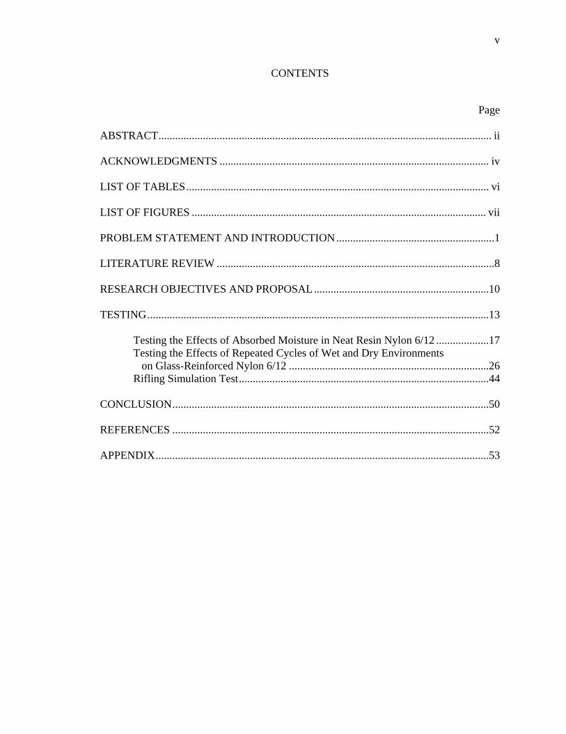
ABSTRACT ........................................................................................................................ ii ACKNOWLEDGMENTS ................................................................................................. iv LIST OF TABLES ............................................................................................................. vi LIST OF FIGURES .......................................................................................................... vii PROBLEM STATEMENT AND INTRODUCTION .........................................................1 LITERATURE REVIEW ....................................................................................................8 RESEARCH OBJECTIVES AND PROPOSAL ...............................................................10 TESTING ...........................................................................................................................13 Testing the Effects of Absorbed Moisture in Neat Resin Nylon 6/12 ...................17
Testing the Effects of Repeated Cycles of Wet and Dry Environments on Glass-Reinforced Nylon 6/12 ........................................................................26
Rifling Simulation Test ..........................................................................................44 CONCLUSION ..................................................................................................................50 REFERENCES ..................................................................................................................52 APPENDIX ........................................................................................................................53
vi
LIST OF TABLES
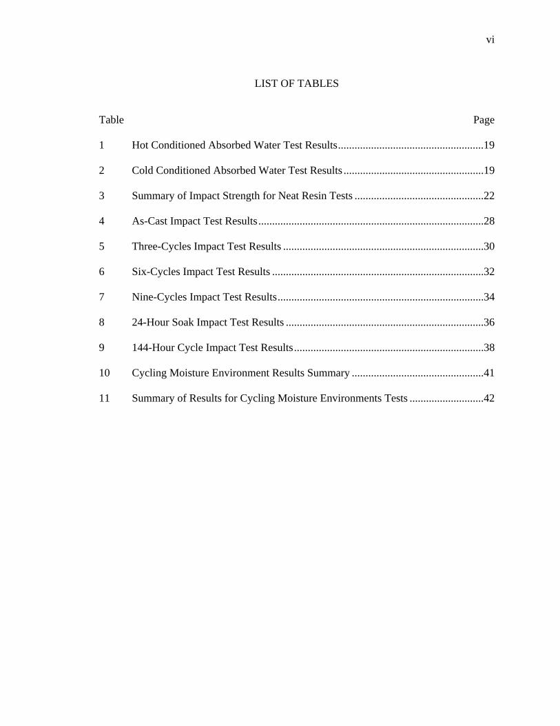
Table Page 1 Hot Conditioned Absorbed Water Test Results .....................................................19 2 Cold Conditioned Absorbed Water Test Results ...................................................19 3 Summary of Impact Strength for Neat Resin Tests ...............................................22 4 As-Cast Impact Test Results ..................................................................................28 5 Three-Cycles Impact Test Results .........................................................................30 6 Six-Cycles Impact Test Results .............................................................................32 7 Nine-Cycles Impact Test Results ...........................................................................34 8 24-Hour Soak Impact Test Results ........................................................................36 9 144-Hour Cycle Impact Test Results .....................................................................38 10 Cycling Moisture Environment Results Summary ................................................41 11 Summary of Results for Cycling Moisture Environments Tests ...........................42

vii
LIST OF FIGURES
Figure Page 1 L7 105mm tank gun Cut model on display at the Deutsches Panzermuseum Munster, Germany. .......................................................2 2 Simple models of a projectile with a rotating band and small section of a rifled barrel with concentric central axes. ............................................3 3 Looking down the central axes of the projectile and barrel section through the barrel section at the projectile. ..............................................................4 4 Simplified cross-section view of a gun Chamber. Section 1 is the freebore region. Section 2 indicates the forcing cone region. Section 3 is the groove and section 4 represents the final land profile. ...........................................5 5 This test fixture holds flat nylon test specimens. ...................................................15 6 Rifling simulating tool. ..........................................................................................15 7 Right half 30 mm projectile mounting fixture. ......................................................16 8 Left half 30 mm projectile mounting fixture. ........................................................16 9 Hot/Wet impact test results. Mean strength: 1.1424 ft*lbf/in. Standard deviation: 0.3919 ft*lbf/in. ....................................................................................20 10 Hot/Dry impact test results. Mean strength: 0.3726 ft*lbf/in. Standard deviation: 0.1221 ft*lbf/in. ....................................................................................20 11 Cold/Wet impact test results. Mean strength: 0.4713 ft*lbf/in. Standard deviation: 0.0984 ft*lbf/in. ....................................................................................21 12 Cold/Dry impact test results. Mean strength: 0.4257 ft*lbf/in. Standard deviation: 0.0271 ft*lbf/in. ....................................................................................21 13 Average impact strengths for neat resin tests. .......................................................22 14 As cast impact strength results. Mean strength: 0.3312 ft*lbf/in. Standard deviation: 0.0167 ft*lbf/in. ....................................................................................28 15 As cast relative hardness results. Mean hardness: 81.47 SHORE D. Standard deviation: 0.5012 SHORE D. .................................................................29
viii
16 Three cycles impact strength results. Mean strength: 0.3329 ft*lbf/in. Standard deviation: 0.0282 ft*lbf/in. .....................................................................30 17 Three cycles relative hardness results. Mean hardness: 80.21 SHORE D. Standard deviation: 0.2713 SHORE D. .................................................................31 18 Six cycles impact strength results. Mean strength: 0.3573 ft*lbf/in. Standard deviation: 0.0353 ft*lbf/in. .....................................................................32 19 Six cycles relative hardness results. Mean hardness: 80.42 SHORE D. Standard deviation: 0.3048 SHORE D. .................................................................33 20 Nine cycles impact strength results. Mean strength: 0.3126 ft*lbf/in. Standard deviation: 0.0212 ft*lbf/in. .....................................................................34 21 Nine cycles relative hardness results. Mean hardness: 80.62 SHORE D. Standard deviation: 0.3393 SHORE D. .................................................................35 22 24-hour soak impact strength results. Mean strength: 0.3710 ft*lbf/in. Standard deviation: 0.0500 ft*lbf/in. .....................................................................36 23 24-hour soak relative hardness results. Mean hardness: 78.81 SHORE D. Standard deviation: 0.4909 SHORE D. .................................................................37 24 144-hour cycle impact strength results. Mean strength: 0.3397 ft*lbf/in. Standard deviation: 0.0450 ft*lbf/in. .....................................................................38 25 144-hour cycle relative hardness results. Mean hardness: 81.11 SHORE D. Standard deviation: 0.4306 SHORE D. .................................................................39 26 Average impact strengths for cycling moisture environment tests. .......................42 27 Average relative hardness for cycling moisture environment tests. ......................43 28 Rifling simulation tool. ..........................................................................................43 29 Hardness plotted against impact strength for the means of each case. ..................44 30 Hardness plotted against impact strength for each test sample. .............................46 31 Mechanical drawing for the rifling simulating tool. ..............................................46 32 Test run at 600 rpm with a depth of 0.065” penetration. .......................................47 33 Test run at 4200 rpm with a depth of 0.065” penetration. Note that there is residual plastic material that stuck to the tool as it melted. ...................................48
PROBLEM STATEMENT AND INTRODUCTION
Certain 30 millimeter munitions are equipped with a glass-reinforced nylon 6/12
rotating band. There are three different configurations of the cartridge equipped with
different projectiles that are of interest to this research. The projectiles are; high
explosive incendiary (HEI), armor piercing incendiary (API) and target practice (TP)
projectiles. All of these different projectiles utilize the same type of rotating band in
either a single or two-band configuration. Because some of the materials used in the API
projectile are hazardous, it is desirable for existing projectiles to have a long storage life.
There is some concern that the rotating bands on these as well as the other projectiles will
deteriorate over time and become brittle, thus compromising the ability for the projectile
to be fired and maintain stability in flight.
Thirty millimeter munitions equipped with a reinforced nylon rotating band are
used in various military applications including the GAU-8/A Avenger found in the Air
Force’s A-10 Thunderbolt II. The GAU-8/A is a seven barrel Gatling gun capable of
firing up to 4,200 rounds per minute with a muzzle velocity of 3,250 ft/sec used by the
Air Force’s A-10 Thunderbolt. Some of the specifications of the GAU-8/A are used in
this paper.
To better understand the problem, a basic understanding of interior ballistics is
necessary. Interior ballistics involves everything that happens once the cartridge is fired
to when the projectile leaves the barrel where exterior ballistics involves everything that
happens to the projectile once it leaves the barrel. A significant deal of how well a
projectile performs after it leaves the barrel is dependent on what happens inside the gun.
2
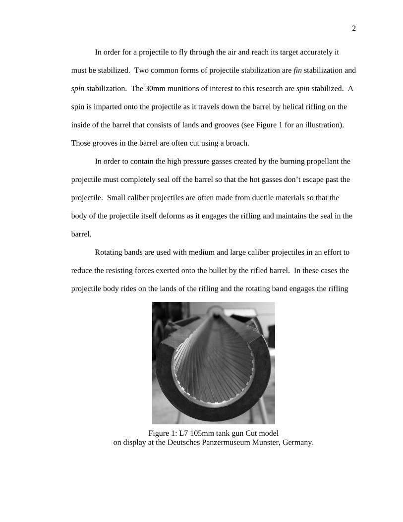
In order for a projectile to fly through the air and reach its target accurately it
must be stabilized. Two common forms of projectile stabilization are fin stabilization and
spin stabilization. The 30mm munitions of interest to this research are spin stabilized. A
spin is imparted onto the projectile as it travels down the barrel by helical rifling on the
inside of the barrel that consists of lands and grooves (see Figure 1 for an illustration).
Those grooves in the barrel are often cut using a broach.
In order to contain the high pressure gasses created by the burning propellant the
projectile must completely seal off the barrel so that the hot gasses don’t escape past the
projectile. Small caliber projectiles are often made from ductile materials so that the
body of the projectile itself deforms as it engages the rifling and maintains the seal in the
barrel.
Rotating bands are used with medium and large caliber projectiles in an effort to
reduce the resisting forces exerted onto the bullet by the rifled barrel. In these cases the
projectile body rides on the lands of the rifling and the rotating band engages the rifling
Figure 1: L7 105mm tank gun Cut model on display at the Deutsches Panzermuseum Munster, Germany.
3
and seals off the grooves in the barrel. The spin is then imparted onto the projectile
through the rotating band as it engages the rifling. Rotating bands also allow for use of
harder materials for projectile bodies which would damage the rifling in a non-rotating
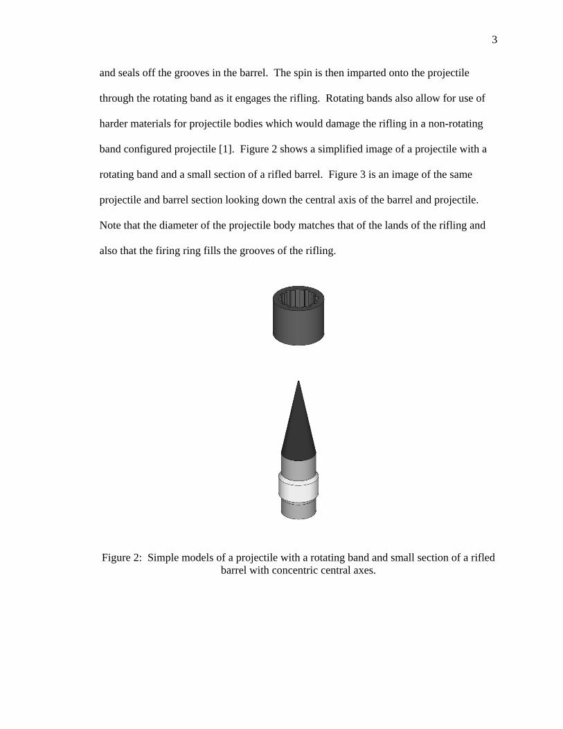
band configured projectile [1]. Figure 2 shows a simplified image of a projectile with a
rotating band and a small section of a rifled barrel. Figure 3 is an image of the same
projectile and barrel section looking down the central axis of the barrel and projectile.
Note that the diameter of the projectile body matches that of the lands of the rifling and
also that the firing ring fills the grooves of the rifling.
Figure 2: Simple models of a projectile with a rotating band and small section of a rifled barrel with concentric central axes.
4
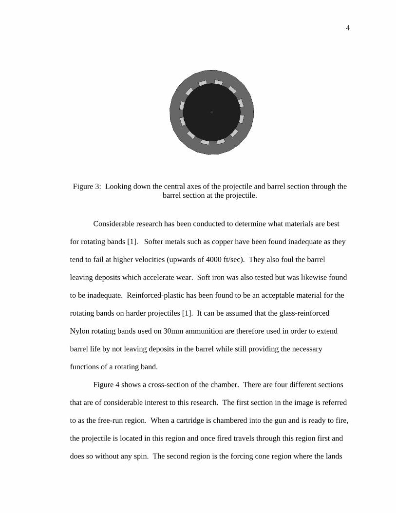
Figure 3: Looking down the central axes of the projectile and barrel section through the barrel section at the projectile.
Considerable research has been conducted to determine what materials are best
for rotating bands [1]. Softer metals such as copper have been found inadequate as they
tend to fail at higher velocities (upwards of 4000 ft/sec). They also foul the barrel
leaving deposits which accelerate wear. Soft iron was also tested but was likewise found
to be inadequate. Reinforced-plastic has been found to be an acceptable material for the
rotating bands on harder projectiles [1]. It can be assumed that the glass-reinforced
Nylon rotating bands used on 30mm ammunition are therefore used in order to extend
barrel life by not leaving deposits in the barrel while still providing the necessary
functions of a rotating band.
Figure 4 shows a cross-section of the chamber. There are four different sections
that are of considerable interest to this research. The first section in the image is referred
to as the free-run region. When a cartridge is chambered into the gun and is ready to fire,
the projectile is located in this region and once fired travels through this region first and
does so without any spin. The second region is the forcing cone region where the lands

5
of the rifling transition into their final profile. Moving away from the free run region
through the forcing cone the lands gradually grow inward toward the center axis of the
barrel until they reach their final height. The projectile first encounters the rifling in this
region. As the projectile travels through this region the rifling will deform the projectile
and in the case of this research the rotating band is what will deform. The third and
fourth regions are the groves and lands, respectively in their final profile throughout the
remaining length of the barrel. In comparison to the length of the barrel, the first and
second regions are short. For the case of the GAU-8/A cannon approximately 0.117” and
0.133”, respectively. In the GAU-8/A cannon the forcing cone has a 3 degree half angle.
The plastic rotating bands that are discussed in this document are composed of
20% glass filled Nylon 6/12. The rotating bands are injection molded onto the
Figure 4: Simplified cross-section view of a gun Chamber. Section 1 is the freebore region. Section 2 indicates the forcing cone region. Section 3 is the groove and section
4 represents the final land profile.
6
projectiles. These projectiles are stored at various locations around the world with a wide
range of temperature and humidity environments.
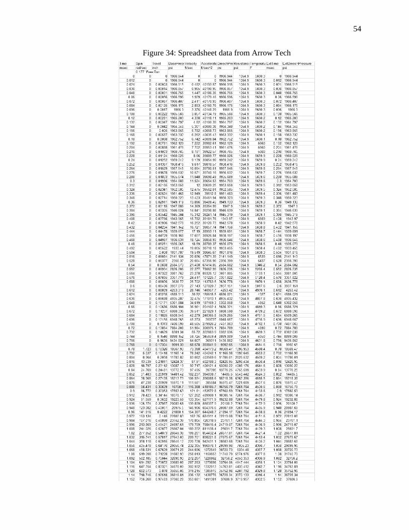
A spreadsheet that tabulates five different cases of free run length was obtained
from Arrow Tech which works with the GAU-8. In each case values are given for: spin,
base pressure, travel, velocity, acceleration, breech pressure, external breech pressure,
resistance, and temperature all with respect to time. From this spreadsheet the data
corresponding to the median free run length of 0.177” is chosen for use in this research.
Using information given to us from Arrow Tech the height of the lands was
calculated from the forcing cone half angle and the length of the cone. This calculation
would give a height of 0.007”. A velocity of 73.4 ft/sec is listed as the velocity of the
projectile as it first impacts the forcing cone and 133.4 ft/sec once the lands’ geometry
has reached its final profile. This transition occurs in roughly 0.108 milliseconds. This
transition of land profile geometry is where the nylon bands experience their primary
deformation. As the bullet travels down the rest of the barrel the bands likely experience
wear and melting as they slide against the barrel. Upon inspecting the nylon bands on a
previously fired bullet it appears the bands experience both plastic deformation that
forces portions of the band up into the groves of the rifling as well as some cutting or
wearing away of band material.
The structural integrity of rotating bands is critical to the stability of the projectile.
If a rotating band were to fail after being deformed by the rifling and separate from the
projectile body the projectile would no longer be balanced about its axis and would no
longer spin about its axis upon leaving the barrel. This would severely compromise the

7
stability of the projectile and would severely limit its ability to accurately fly through the
air.
The objective of this research is to determine whether or not significant
degradation occurs as a result of varying temperature and humidity environments such
that it would pose a serious risk to the integrity of the ammunition. The rotating bands
will need to be able to remain ductile enough during firing so as not to fracture when
engaging the rifling thus compromising the projectile’s performance. Because a change
in impact strength could indicate a change in ductility, this research focuses heavily on
the impact strength of both glass-reinforced and neat resin nylon 6/12.
Two separate tests are conducted in order to investigate the how moisture and
warm environments affect glass-reinforced nylon 6/12. One of these tests demonstrates
the change in the impact properties of nylon in a neat resin configuration. Since impact
strength is so highly dependent on the matrix material’s properties, we will assume a
similar result for glass-reinforced nylons. Additional testing investigates the effects of
cycling wet and dry environments on glass-reinforced nylon 6/12.
A third conceptual test is also designed and run in an attempt to simulate the
deformation experienced by the rotating band as it engages the rifling. This test makes
use of a specialized tool that will represent the rifling and will be conducted on a
horizontal milling machine.
8
LITERATURE REVIEW
Nylon degrades in environments with UV light. However UV radiation is not
present in any of the storage environments. The main variables in storage are
temperature and humidity. Previous research shows that moisture absorption, or
hydrolysis, in nylon composites has a significant effect in the properties of the material.
Hydrolysis has been found to significantly increase the toughness of nylon and
conversely a lack of absorbed moisture embrittles nylon [2,3]. Hydrolysis has also been
found to expand surface defects and attack the fiber-matrix interface [4]. Bernstein et al.
explain that the increase in impact strength and decrease in tensile strength is expected
when nylon has absorbed moisture. He further explains that the hydrolysis of the amide
bond in nylon is the reverse reaction for the simplified synthesis of nylon [5].
The result of repeated hydrolysis and drying is in question. Miri et al. reports that
resulting expansion of surface defects and degradation of the fiber-matrix interface
results in lower impact performance or lower energy absorption upon impact [4]. Strong
et al. explains however that a lower fiber-matrix bond will result in higher impact
strength because the weaker bond allows the reinforcement to slip in the matrix while
also helping to mitigate crack propagation [2,6]. Perhaps repeated hydrolysis and drying
will create enough defects in the material to cancel out any advantages gained by the
resulting weaker fiber-matrix bond.
Elevated temperatures accelerate hydrolysis in nylons. This fact has been used in
accelerated aging studies [5]. While elevated temperatures do increase the rate at which
moisture is absorbed into nylons, it has been found that the increase in temperature does
not by itself enhance the degradation of nylon [7].
9
It has also been found that when polymers are deformed their mechanical
properties are changed due to the alignment of polymer molecules [8]. This may be
advantageous when using polymer rotating bands vs. the more typical malleable metals
such as copper. Crack propagation occurs in the direction of fiber alignment and energy
required to propagate a crack increases as fiber content increases. A strong bond between
matrix and fiber increases the toughness of the material. If a propagating crack meets a
fiber in a compound with good matrix/reinforcement bonded material, the fiber will need
to crack rather than de-bond from the matrix. Manufacturing method and conditions have
a significant effect on the material as well [9].
Impact strength is an indication of a material’s ability to absorb energy due to an
impact without failing. Strong explains that the ability of composite materials to quickly
diffuse impact energy is highly dependent on the matrix material’s ability to transform
impact energy to some other form of energy [10]. Since impact strength in composites is
a matrix dominant property, the effects of moisture and temperature on the glass
reinforcement wasn’t taken into consideration in this research.
10
RESEARCH OBJECTIVES AND PROPOSAL
1. Test the effects of absorbed moisture in nylon neat resin 6/12 and how temperature affects absorption • Use variables of wet and dry (conditioned soaked in water vs. in atmospheric air)
and hot and cold (60° C and 0° C) • Measure break energy using an Izod impact test • Uncertainty analysis • Perform a t-test to investigate significant differences in impact strength
2. Test the effects of cycling moisture environments on glass-reinforced nylon 6/12 • Use variables of the number of cycles the specimens undergo. • Measure break energy using an Izod impact test • Measure relative hardness using a shore D durometer. • Perform an uncertainty analysis • Perform a t-test to investigate significant differences in impact strength and
hardness
3. Conceptualize and attempt a test that would simulate/represent the deformation that the rotating bands experience when they engage the rifling in the barrel using a horizontal milling machine • Using spindle speed and depth of penetration as test variables • Test only nylon samples, not rotating bands (logistics difficulty) • Report on findings of the test and give suggestions for further testing.
Research Objective 1
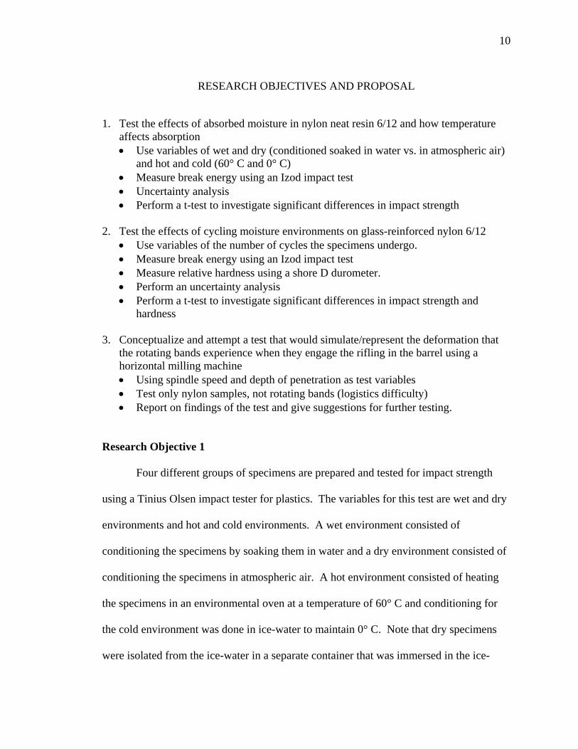
Four different groups of specimens are prepared and tested for impact strength
using a Tinius Olsen impact tester for plastics. The variables for this test are wet and dry
environments and hot and cold environments. A wet environment consisted of
conditioning the specimens by soaking them in water and a dry environment consisted of
conditioning the specimens in atmospheric air. A hot environment consisted of heating
the specimens in an environmental oven at a temperature of 60° C and conditioning for
the cold environment was done in ice-water to maintain 0° C. Note that dry specimens
were isolated from the ice-water in a separate container that was immersed in the ice-

11
water to prevent moisture absorption. Specimen conditioning lasts for 24 hours. After
measuring the break energy of each sample a t-test is performed to determine any
significant difference in impact strength that results from the conditioning environments.
An uncertainty analysis is also performed to accompany this test.
Research Objective 2
Four different groups of specimens are tested in the cycling moisture environment
test. The only variable in this test is the number of cycles that a specimen group
experiences. One cycle will consist of samples soaking in water for 12 hours at 60° C
followed by drying in atmospheric air for another 12 hours at 60° C after which the
following cycle begins immediately. After the specified number of cycles has been
reached the specimens are allowed to cool to room temperature (approximately 21°) for
at least 30 minutes. Once the specimen is cooled the impact strength is measured through
an Izod impact test. Each specimen’s respective hardness is also measured using a Shore
D scale durometer. A t-test is then performed as in the test above to determine if there is
any statistically significant difference in the impact strength and hardness of the
specimens that result from the conditioning environment. An uncertainty analysis is also
performed to accompany this test.
Research Objective 3
A separate test that would simulate the deformation that the rotating band
experiences has also been developed. This test allows for the testing of flat nylon
specimens as well as the rotating bands while they are on the projectile body. The
variables for this test are the spindle speed and the depth of penetration. The fast speed
will be roughly 4200 rpm and the slow speed will be 600 rpm. The shallow depth will be
12
0.01” and the deep penetration depth will be 0.065”. The objective of this test is to
generate brittle failure from a deformation similar to the deformation that the rotating
band experiences. Samples are tested in an as cast condition since it is found that in that
state they have a lower impact strength than those that have absorbed moisture.

13
TESTING
The dynamic deformation of a bullet as it impacts the rifling in the barrel is very
complex. Finding a test that captures all of the characteristics of a bullet being deformed
in a barrel without actually firing the projectile would be extremely difficult. Because of
the high rate of deformation that the rotating band experiences, an impact test seems to be
most appropriate to evaluate the integrity of nylon after having been conditioned in
different environments.
To better understand failure due to impact in glass-reinforced nylon 6/12, it is
proposed that the relationship of impact strength and exposure to moisture environments
be investigated. Two tests are utilized to help find a correlation between the different
storage environments and failure during impact. These two tests use a Tinius Olsen
impact tester with typical Izod impact test specimens. One of the impact tests will
investigate the change in material properties of neat resin nylon 6/12 specimens when
they are subjected to wet and dry environments in both hot and cold conditions. The
second of the two impact tests will investigate the effects of cycling wet and dry
environments on glass-reinforced nylon 6/12 specimens. The test specimens in this test
are composed of 33% glass filled nylon 6/12.
The deformation experienced by the rotating bands appears to be a matrix
dominant deformation and serves as justification to using neat resin test samples in the
first test and then inferring the results to those of glass-reinforced materials with a similar
matrix.
For the first test, samples are preconditioned in dry and wet as well as hot and
cold environments and tested for impact strength. This test compares the impact strength
14
of samples that have been subjected to environments that accommodate hydrolysis
against those that are conditioned in dry environments. It also shows the effect of
temperature on hydrolysis.
The second test investigates the effects of cycling samples from wet and dry
environments at an elevated temperature to accelerate the hydrolysis of the samples. In
addition to testing the impact strength of the samples, a correlation between hardness and
impact strength will be sought. Test samples are conditioned in environments that cycle
between wet and dry.
A third test is conducted to simulate the deformation of the nylon rotating band as
it impacts the forcing cone portion of the rifling. Because of the difficulty in obtaining
actual projectiles, test specimens are comprised of 1/8” thick sheets of glass-reinforced
nylon 6/12 approximately 2.5” by 4”. A horizontal milling machine is used in addition to
a specialized tool (see Figure 6) that represents the rifling of the gun barrel. A milling
machine was chosen as it provides a rigid test platform in addition to great control of
repeatability, speed and depth of penetration. A test specimen is loaded into the fixture
(see Figure 5) on the milling machine and then varying spindle speeds and depth of
penetration are used to investigate their respective effect on the brittle failure of the
respective test specimens. After the test has been performed a visual inspection is made
to look for any cracks. The variables for this test are spindle speed and depth of
penetration. Since the objective of this test is to generate brittle failure in the test
specimens, all test specimens will be tested in their as-cast condition as this condition is
found to have the lowest impact strength. A fixture that would adequately hold and retain
15
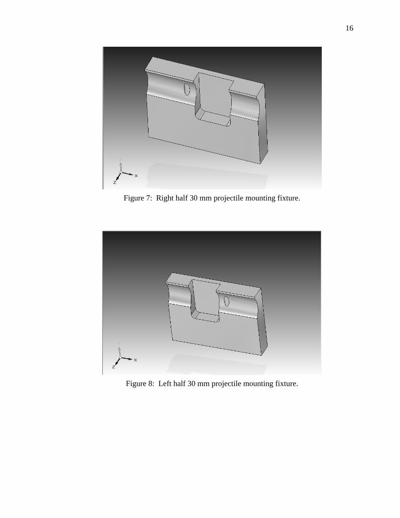
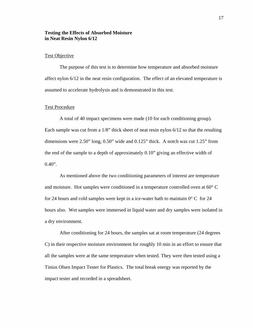
the projectiles (see Figures 7 and 8) could be used in the event that some projectiles
become available to test.
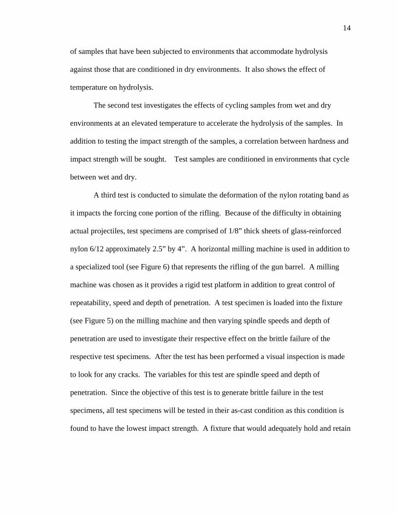
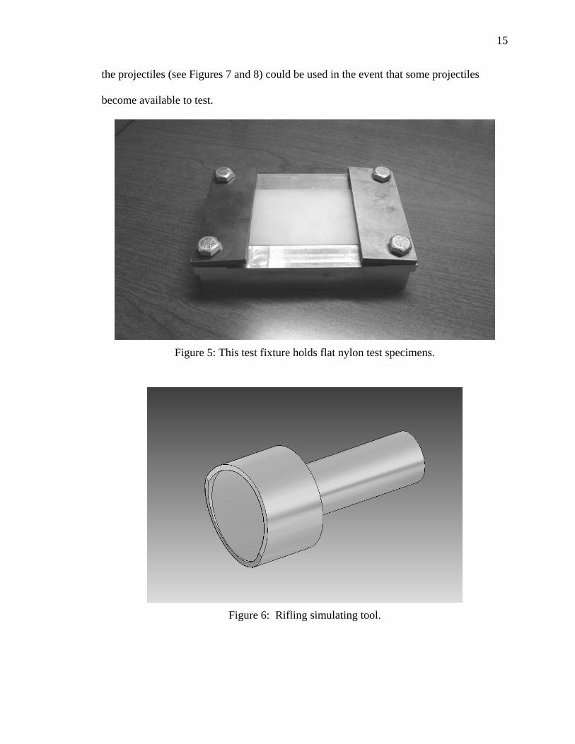
Figure 5: This test fixture holds flat nylon test specimens.
Figure 6: Rifling simulating tool.
16
Figure 7: Right half 30 mm projectile mounting fixture.
Figure 8: Left half 30 mm projectile mounting fixture.
17
Testing the Effects of Absorbed Moisture in Neat Resin Nylon 6/12 Test Objective
The purpose of this test is to determine how temperature and absorbed moisture
affect nylon 6/12 in the neat resin configuration. The effect of an elevated temperature is
assumed to accelerate hydrolysis and is demonstrated in this test.
Test Procedure
A total of 40 impact specimens were made (10 for each conditioning group).
Each sample was cut from a 1/8” thick sheet of neat resin nylon 6/12 so that the resulting
dimensions were 2.50” long, 0.50” wide and 0.125” thick. A notch was cut 1.25” from
the end of the sample to a depth of approximately 0.10” giving an effective width of
0.40”.
As mentioned above the two conditioning parameters of interest are temperature
and moisture. Hot samples were conditioned in a temperature controlled oven at 60° C
for 24 hours and cold samples were kept in a ice-water bath to maintain 0° C for 24
hours also. Wet samples were immersed in liquid water and dry samples were isolated in
a dry environment.
After conditioning for 24 hours, the samples sat at room temperature (24 degrees
C) in their respective moisture environment for roughly 10 min in an effort to ensure that
all the samples were at the same temperature when tested. They were then tested using a
Tinius Olsen Impact Tester for Plastics. The total break energy was reported by the
impact tester and recorded in a spreadsheet.
18
For this case the impact tester was configured so that the maximum amount of
available energy is 2.0833 ft*lbf. The release point of the pendulum can be changed in
order to reduce the stored energy in the pendulum. For this case a total energy of 1.9696
ft*lbf was the capacity of the pendulum when tested.
Test Results
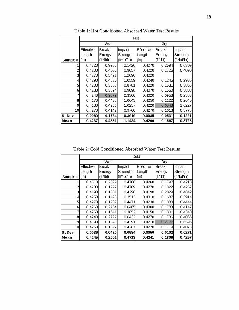
The effective length behind the notch of each specimen was measured using a pair
of venire calipers. Impact strength is calculated using the effective length and the break
energy for each sample. Tables 1 and 2 show the results of the effective length (in),
break energy (ft*lbf), and the calculated impact strength (ft*lbf) for each sample. Note
that in Table 1, sample #3 in the dry samples does not have a value for break energy.
That is because the display on the machine was not cleared before the test was performed
and a reading was not measured when the sample was broken. The highlighted cells
indicate outliers that were found according to Chauvenet’s criterion. Chauvenet’s
criterion states that a sample measurement can be considered for rejection if the
probability for obtaining its difference from the mean is less than 1/(2*N) where N is the
total number of samples. The random standard uncertainties are included in both Tables
1 and 2 for all of the measured values without the outliers being factored into the
calculation.
The following plots show each sample’s impact strength potted against each
case’s respective mean. The outliers are not shown in the plots and the associated means
and standard deviations for the strength are representative of the sample population
without the outliers.
19
Table 1: Hot Conditioned Absorbed Water Test Results
Effective Length (in)
Break Energy (ft*lbf)
Impact Strength (ft*lbf/in)
Effective Length (in)
Break Energy (ft*lbf)
Impact Strength (ft*lbf/in)
1 0.4320 0.9256 2.1426 0.4270 0.2694 0.63092 0.4200 0.4056 0.9657 0.4220 0.1726 0.40903 0.4270 0.5421 1.2696 0.42204 0.4290 0.4530 1.0559 0.4240 0.1245 0.29365 0.4200 0.3688 0.8781 0.4220 0.1631 0.38656 0.4280 0.3894 0.9098 0.4070 0.1550 0.38087 0.4240 0.9879 2.3300 0.4020 0.0958 0.23838 0.4170 0.4438 1.0643 0.4250 0.1122 0.26409 0.4130 0.4236 1.0257 0.4220 0.6848 1.6227
10 0.4270 0.4142 0.9700 0.4270 0.1613 0.3778St Dev 0.0060 0.1724 0.3919 0.0085 0.0531 0.1221Mean 0.4237 0.4851 1.1424 0.4200 0.1567 0.3726
Sample #
HotWet Dry
Table 2: Cold Conditioned Absorbed Water Test Results
Effective Length (in)
Break Energy (ft*lbf)
Impact Strength (ft*lbf/in)
Effective Length (in)
Break Energy (ft*lbf)
Impact Strength (ft*lbf/in)
1 0.4310 0.2029 0.4708 0.4260 0.1797 0.42182 0.4230 0.1992 0.4709 0.4270 0.1822 0.42673 0.4190 0.1801 0.4298 0.4190 0.2029 0.48424 0.4250 0.1493 0.3513 0.4310 0.1687 0.39145 0.4270 0.1909 0.4471 0.4230 0.1880 0.44446 0.4260 0.2754 0.6465 0.4300 0.1783 0.41477 0.4260 0.1641 0.3852 0.4150 0.1801 0.43408 0.4240 0.2727 0.6432 0.4270 0.1736 0.40669 0.4190 0.1840 0.4391 0.4210 0.2777 0.6596
10 0.4250 0.1822 0.4287 0.4220 0.1719 0.4073St Dev 0.0036 0.0420 0.0984 0.0050 0.0102 0.0271Mean 0.4245 0.2001 0.4713 0.4241 0.1806 0.4257
Sample #
ColdWet Dry
20
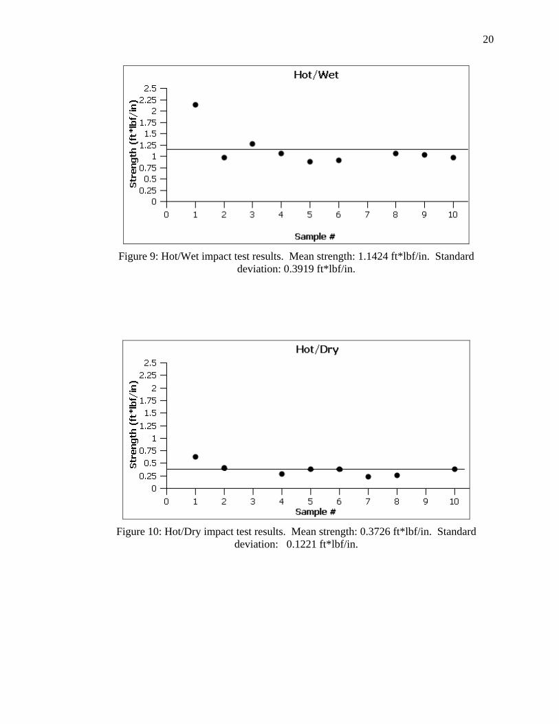
Figure 9: Hot/Wet impact test results. Mean strength: 1.1424 ft*lbf/in. Standard deviation: 0.3919 ft*lbf/in.
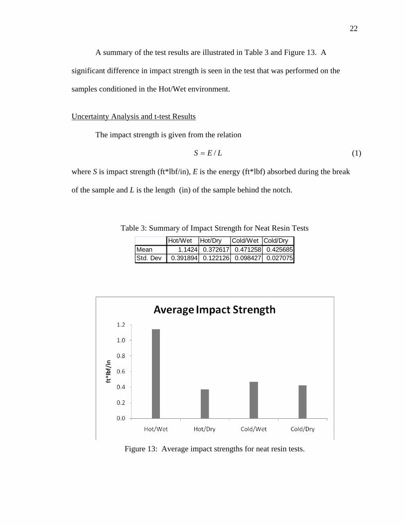
Figure 10: Hot/Dry impact test results. Mean strength: 0.3726 ft*lbf/in. Standard deviation: 0.1221 ft*lbf/in.

21
Figure 11: Cold/Wet impact test results. Mean strength: 0.4713 ft*lbf/in. Standard deviation: 0.0984 ft*lbf/in.
Figure 12: Cold/Dry impact test results. Mean strength: 0.4257 ft*lbf/in. Standard deviation: 0.0271 ft*lbf/in.
22
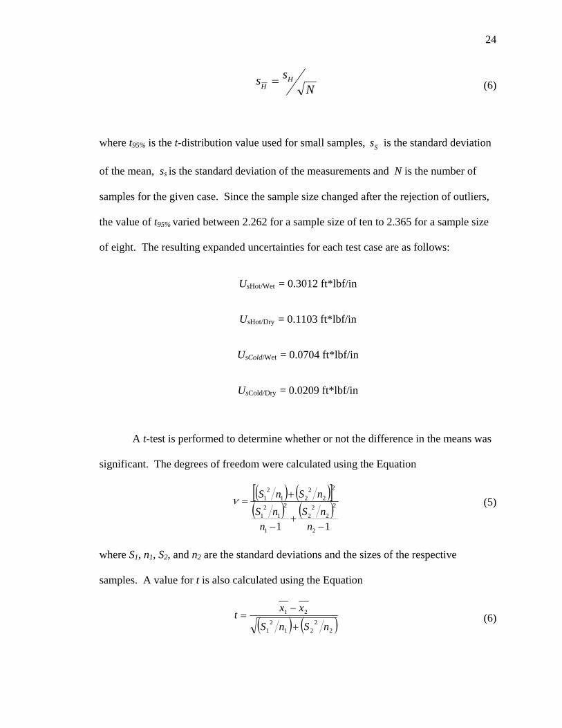
A summary of the test results are illustrated in Table 3 and Figure 13. A
significant difference in impact strength is seen in the test that was performed on the
samples conditioned in the Hot/Wet environment.
Uncertainty Analysis and t-test Results
The impact strength is given from the relation
LES /= (1)
where S is impact strength (ft*lbf/in), E is the energy (ft*lbf) absorbed during the break
of the sample and L is the length (in) of the sample behind the notch.
Table 3: Summary of Impact Strength for Neat Resin Tests Hot/Wet Hot/Dry Cold/Wet Cold/Dry
Mean 1.1424 0.372617 0.471258 0.425685Std. Dev 0.391894 0.122126 0.098427 0.027075
Figure 13: Average impact strengths for neat resin tests.

23
The calipers used to measure the length “L” for each sample had a resolution of
0.001”. This results in a systematic uncertainty in length ( bL) of 0.00025”.
The reported accuracy of the impact tester is 0.03% of the capacity of the tester.
For the weight configuration that was used in this test, the capacity of the tester was
1.9696 ft*lbf. This capacity represents the potential energy stored in the pendulum. The
resulting systematic uncertainty for the absorbed energy at impact (bE) is 5.91E-4 ft*lbf.
The systematic uncertainty of impact strength is found using the equation
( ) ( ) ( )ELLES bLS
ESb
LSb
ESb ⎟
⎠⎞
⎜⎝⎛∂∂
⎟⎠⎞
⎜⎝⎛∂∂
+⎟⎠⎞
⎜⎝⎛∂∂
+⎟⎠⎞
⎜⎝⎛∂∂
= 222
22
(2)
where bEL represents the correlated systematic uncertainties in E and L. In this case there
is no correlation in E and L which means that bEL = 0. Equation (2) reduces to
( ) ( )22
22
LES bLSb
ESb ⎟
⎠⎞
⎜⎝⎛∂∂
+⎟⎠⎞
⎜⎝⎛∂∂
= . (3)
The 95% confidence expanded uncertainty for each test case is computed from the
Equation
( ) ( )22SSS pbU += (4)
where ps is the precision uncertainty and
)(%95 SS stp = (5)
and
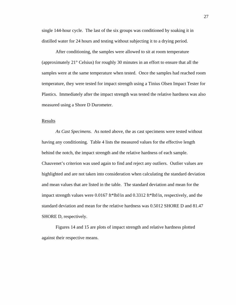
24
Nss H
H = (6)
where t95% is the t-distribution value used for small samples, Ss is the standard deviation
of the mean, ss is the standard deviation of the measurements and N is the number of
samples for the given case. Since the sample size changed after the rejection of outliers,
the value of t95% varied between 2.262 for a sample size of ten to 2.365 for a sample size
of eight. The resulting expanded uncertainties for each test case are as follows:
UsHot/Wet = 0.3012 ft*lbf/in
UsHot/Dry = 0.1103 ft*lbf/in
UsCold/Wet = 0.0704 ft*lbf/in
UsCold/Dry = 0.0209 ft*lbf/in
A t-test is performed to determine whether or not the difference in the means was
significant. The degrees of freedom were calculated using the Equation
( ) ( )[ ]( ) ( )
11 2
2
22
2
1
2
12
1
2
22
212
1
−+
−
+=
nnS
nnS
nSnSν (5)
where S1, n1, S2, and n2 are the standard deviations and the sizes of the respective
samples. A value for t is also calculated using the Equation
( ) ( )22
212
1
21
nSnS
xxt
+
−=
(6)

25
where 1x and 2x are the respective sample means. The t value calculated in Equation (6)
is compared to the t value for the corresponding degree of freedom calculated in Equation
5 (rounded to the nearest integer) and the desired confidence interval. When the
calculated value of t is greater than that listed in the chart, it is an indication that there is a
significant difference in the means being compared.
For a 95% confidence interval the t-test showed that the only significant
difference in means was the mean of the Hot/Wet samples compared to that of the other
three tests. This is apparent in the plots. Outliers were omitted from this test as in the
previous tests.
Conclusions for Testing the Effects of Moisture Absorption in Neat Resin Nylon 6/12
From this test one could conclude that the combination of higher temperatures
will accelerate hydrolysis. Absorbed moisture from the storage environment will
increase the impact strength of nylon 6/12. This test only addresses the effect of
absorbed moisture. It is possible that the increase in impact strength could go away if the
nylon of interest were removed from a wet environment and placed in a dry environment
for a prolonged period of time. Repeated cycles of these two variables may have
significant effects on the impact strength in nylon materials and will be investigated in
following test.

26
Testing the Effects of Repeated Cycles of Wet and Dry Environments on Glass-Reinforced Nylon 6/12 Test Objective
The purpose of this test is to determine the effects of cycling glass-reinforced
nylon 6/12 in wet and dry environments. Also, because the previous test was conducted
using neat resin nylon one case will also be run to investigate how absorbed moisture
affects the impact strength of glass-reinforced nylon. In addition to investigating impact
strength, the relative hardness will also be measured to determine if there is a significant
relationship between hardness and impact strength.
Test Procedure
Set up for testing repeated cycles of wet and dry environments is similar to the
test above. Sixty impact specimens for six different groups of 10 samples are made with
the same dimensions and characteristics as the previous test. These samples, however,
are composed of a 33% glass filled nylon 6/12.
The first group of 10 samples are tested in the as cast condition to give a
benchmark to compare against. Four groups of specimens are conditioned by cycling
them in wet and dry environments. Each cycle consisted of a period of being soaked in
distilled water at 60° Celsius and a drying period also at 60° Celsius. The wet and dry
periods are each half of the length of the cycle. Three of the four groups mentioned
above were conditioned with a 24-hour cycle length for 3, 6, and 9 cycles. Each 24 hour
cycle consisted of 12 hours in the wet environment followed by 12 hours in the dry
environment. The fourth of the four groups mentioned above was conditioned with a
27
single 144-hour cycle. The last of the six groups was conditioned by soaking it in
distilled water for 24 hours and testing without subjecting it to a drying period.
After conditioning, the samples were allowed to sit at room temperature
(approximately 21° Celsius) for roughly 30 minutes in an effort to ensure that all the
samples were at the same temperature when tested. Once the samples had reached room
temperature, they were tested for impact strength using a Tinius Olsen Impact Tester for
Plastics. Immediately after the impact strength was tested the relative hardness was also
measured using a Shore D Durometer.
Results
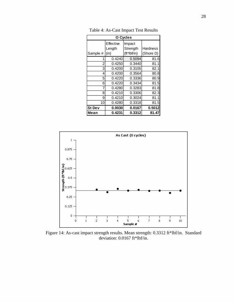
As Cast Specimens. As noted above, the as cast specimens were tested without
having any conditioning. Table 4 lists the measured values for the effective length
behind the notch, the impact strength and the relative hardness of each sample.
Chauvenet’s criterion was used again to find and reject any outliers. Outlier values are
highlighted and are not taken into consideration when calculating the standard deviation
and mean values that are listed in the table. The standard deviation and mean for the
impact strength values were 0.0167 ft*lbf/in and 0.3312 ft*lbf/in, respectively, and the
standard deviation and mean for the relative hardness was 0.5012 SHORE D and 81.47
SHORE D, respectively.
Figures 14 and 15 are plots of impact strength and relative hardness plotted
against their respective means.
28
Table 4: As-Cast Impact Test Results
Sample #
Effective Length (in)
Impact Strength (ft*lbf/in)
Hardness (Shore D)
1 0.4240 0.5094 81.62 0.4250 0.3440 81.13 0.4200 0.3105 82.14 0.4200 0.3564 80.85 0.4220 0.3336 80.96 0.4220 0.3434 81.57 0.4280 0.3283 81.88 0.4210 0.3306 82.39 0.4210 0.3024 81.1
10 0.4280 0.3318 81.5St Dev 0.0030 0.0167 0.5012Mean 0.4231 0.3312 81.47
O Cycles
Figure 14: As-cast impact strength results. Mean strength: 0.3312 ft*lbf/in. Standard deviation: 0.0167 ft*lbf/in.

29
Figure 15: As-cast relative hardness results. Mean hardness: 81.47 SHORE D. Standard deviation: 0.5012 SHORE D.
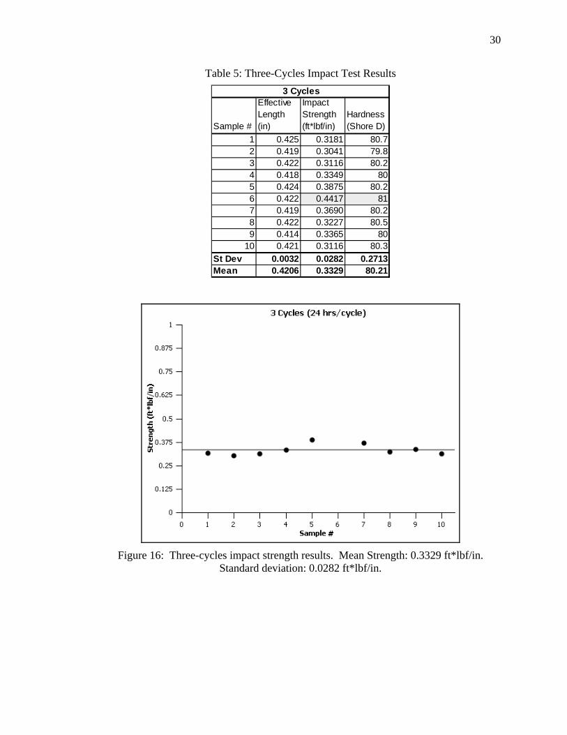
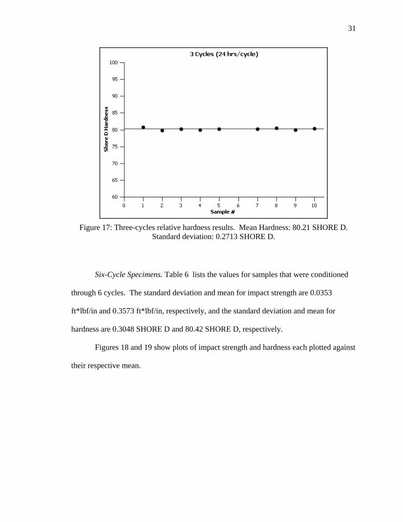
Three-Cycle Specimens. Table 5 lists the measured values for the samples that
were conditioned through three cycles of wet and dry environments. Impact strength and
hardness for sample #6 were found to be outliers using Chauvenet’s criterion. The
standard deviation and mean for the impact strength are 0.0282 ft*lbf/in and 0.3329
ft*lbf/in, respectively and the standard deviation and mean for the hardness are 0.2713
SHORE D and 80.21 SHORE D, respectively.
Figures 16 and 17 show impact strength plotted against their respective means.
Note that outliers are omitted from the plots.
30
Table 5: Three-Cycles Impact Test Results
Sample #
Effective Length (in)
Impact Strength (ft*lbf/in)
Hardness (Shore D)
1 0.425 0.3181 80.72 0.419 0.3041 79.83 0.422 0.3116 80.24 0.418 0.3349 805 0.424 0.3875 80.26 0.422 0.4417 817 0.419 0.3690 80.28 0.422 0.3227 80.59 0.414 0.3365 80
10 0.421 0.3116 80.3St Dev 0.0032 0.0282 0.2713Mean 0.4206 0.3329 80.21
3 Cycles
Figure 16: Three-cycles impact strength results. Mean Strength: 0.3329 ft*lbf/in. Standard deviation: 0.0282 ft*lbf/in.
31
Figure 17: Three-cycles relative hardness results. Mean Hardness: 80.21 SHORE D. Standard deviation: 0.2713 SHORE D.
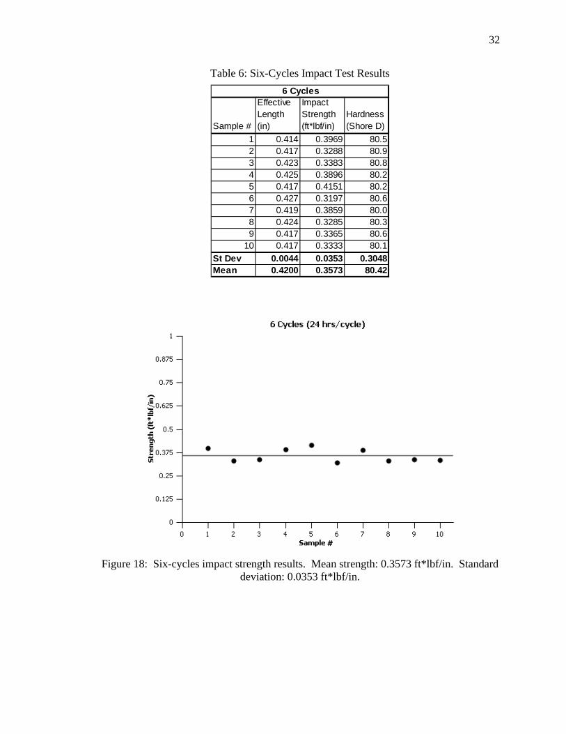
Six-Cycle Specimens. Table 6 lists the values for samples that were conditioned
through 6 cycles. The standard deviation and mean for impact strength are 0.0353
ft*lbf/in and 0.3573 ft*lbf/in, respectively, and the standard deviation and mean for
hardness are 0.3048 SHORE D and 80.42 SHORE D, respectively.
Figures 18 and 19 show plots of impact strength and hardness each plotted against
their respective mean.
32
Table 6: Six-Cycles Impact Test Results
Sample #
Effective Length (in)
Impact Strength (ft*lbf/in)
Hardness (Shore D)
1 0.414 0.3969 80.52 0.417 0.3288 80.93 0.423 0.3383 80.84 0.425 0.3896 80.25 0.417 0.4151 80.26 0.427 0.3197 80.67 0.419 0.3859 80.08 0.424 0.3285 80.39 0.417 0.3365 80.6
10 0.417 0.3333 80.1St Dev 0.0044 0.0353 0.3048Mean 0.4200 0.3573 80.42
6 Cycles
Figure 18: Six-cycles impact strength results. Mean strength: 0.3573 ft*lbf/in. Standard deviation: 0.0353 ft*lbf/in.
33
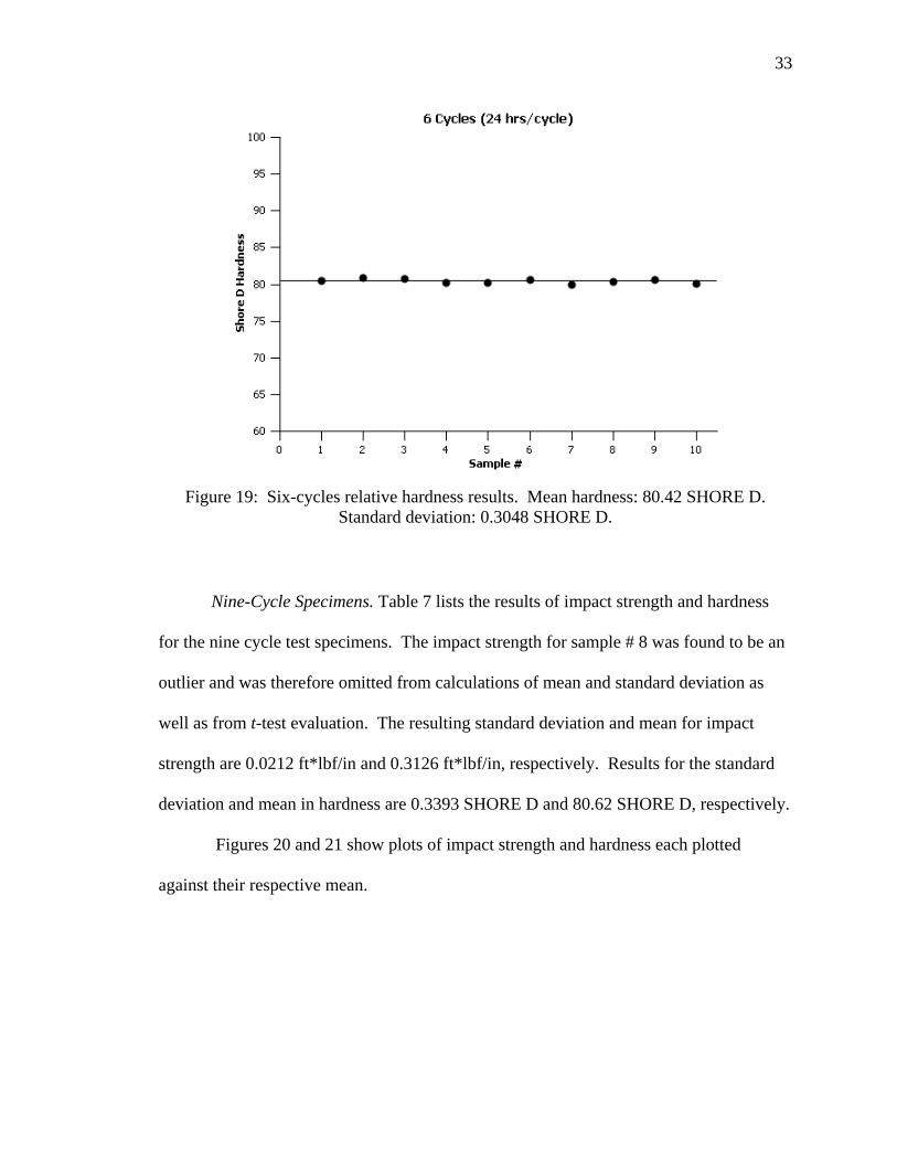
Figure 19: Six-cycles relative hardness results. Mean hardness: 80.42 SHORE D. Standard deviation: 0.3048 SHORE D.
Nine-Cycle Specimens. Table 7 lists the results of impact strength and hardness
for the nine cycle test specimens. The impact strength for sample # 8 was found to be an
outlier and was therefore omitted from calculations of mean and standard deviation as
well as from t-test evaluation. The resulting standard deviation and mean for impact
strength are 0.0212 ft*lbf/in and 0.3126 ft*lbf/in, respectively. Results for the standard
deviation and mean in hardness are 0.3393 SHORE D and 80.62 SHORE D, respectively.
Figures 20 and 21 show plots of impact strength and hardness each plotted
against their respective mean.
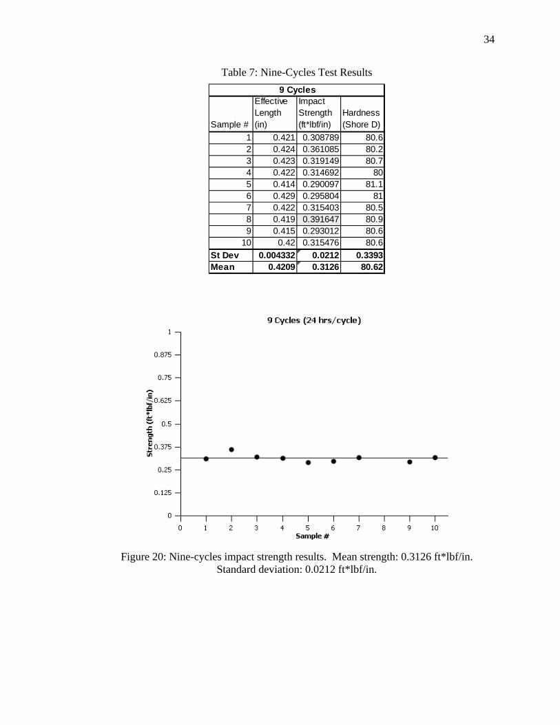
34
Table 7: Nine-Cycles Test Results
Sample #
Effective Length (in)
Impact Strength (ft*lbf/in)
Hardness (Shore D)
1 0.421 0.308789 80.62 0.424 0.361085 80.23 0.423 0.319149 80.74 0.422 0.314692 805 0.414 0.290097 81.16 0.429 0.295804 817 0.422 0.315403 80.58 0.419 0.391647 80.99 0.415 0.293012 80.6
10 0.42 0.315476 80.6St Dev 0.004332 0.0212 0.3393Mean 0.4209 0.3126 80.62
9 Cycles
Figure 20: Nine-cycles impact strength results. Mean strength: 0.3126 ft*lbf/in. Standard deviation: 0.0212 ft*lbf/in.

35
Figure 21: Nine-cycles relative hardness results. Mean hardness: 80.62 SHORE D. Standard deviation: 0.3393 SHORE D.
Twenty-four-Hour Soak Specimens. Table 9 lists the resulting measurements for
the samples that were soaked in water for 24 hours and then tested without drying the
samples. The standard deviation and mean for impact strength are 0.0500 ft*lbf/in and
0.3710 ft*lbf/in, respectively. The standard deviation and mean for hardness
measurements are 0.4904 SHORE D and 78.81 SHORE D, respectively.
Figures 24 and 25 plot impact strength and hardness for each sample plotted
against their respective means.
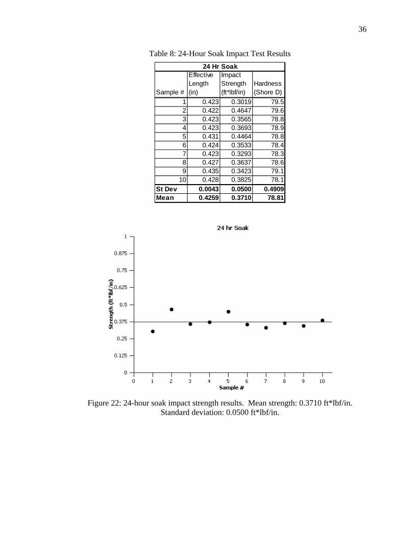
36
Table 8: 24-Hour Soak Impact Test Results
Sample #
Effective Length (in)
Impact Strength (ft*lbf/in)
Hardness (Shore D)
1 0.423 0.3019 79.52 0.422 0.4647 79.63 0.423 0.3565 78.84 0.423 0.3693 78.95 0.431 0.4464 78.86 0.424 0.3533 78.47 0.423 0.3293 78.38 0.427 0.3637 78.69 0.435 0.3423 79.1
10 0.428 0.3825 78.1St Dev 0.0043 0.0500 0.4909Mean 0.4259 0.3710 78.81
24 Hr Soak
Figure 22: 24-hour soak impact strength results. Mean strength: 0.3710 ft*lbf/in. Standard deviation: 0.0500 ft*lbf/in.
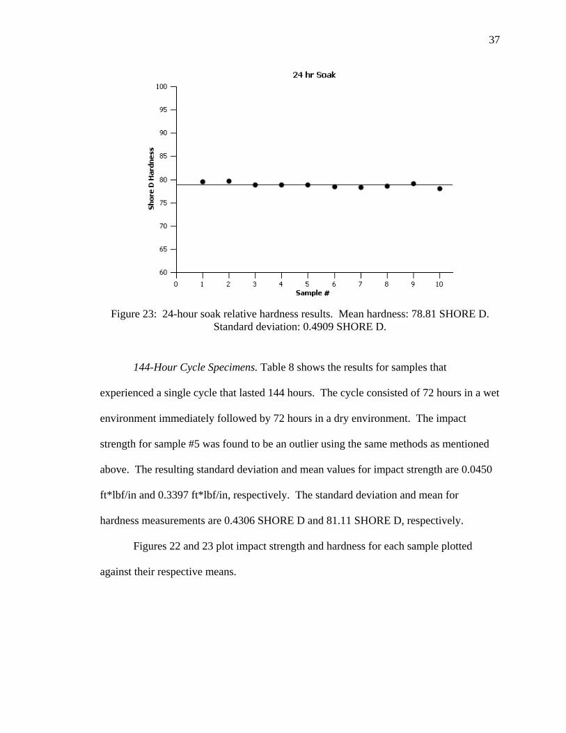
37
Figure 23: 24-hour soak relative hardness results. Mean hardness: 78.81 SHORE D. Standard deviation: 0.4909 SHORE D.
144-Hour Cycle Specimens. Table 8 shows the results for samples that
experienced a single cycle that lasted 144 hours. The cycle consisted of 72 hours in a wet
environment immediately followed by 72 hours in a dry environment. The impact
strength for sample #5 was found to be an outlier using the same methods as mentioned
above. The resulting standard deviation and mean values for impact strength are 0.0450
ft*lbf/in and 0.3397 ft*lbf/in, respectively. The standard deviation and mean for
hardness measurements are 0.4306 SHORE D and 81.11 SHORE D, respectively.
Figures 22 and 23 plot impact strength and hardness for each sample plotted
against their respective means.

38
Table 9: 144-Hour Cycle Impact Test Results
Sample #
Effective Length (in)
Impact Strength (ft*lbf/in)
Hardness (Shore D)
1 0.435 0.390805 80.72 0.438 0.380594 80.53 0.426 0.287559 80.64 0.425 0.289647 81.55 0.428 0.532477 81.36 0.443 0.341986 81.37 0.421 0.320501 81.08 0.439 0.306164 81.79 0.438 0.411111 81.6
10 0.423 0.328671 80.9St Dev 0.0078 0.0450 0.4306Mean 0.4316 0.3397 81.11
144 Hr Cycle
Figure 24: 144-hour cycle impact strength results. Mean strength: 0.3397 ft*lbf/in. Standard deviation: 0.0450 ft*lbf/in.

39
Figure 25: 144-hour cycle relative hardness results. Mean hardness: 81.11 SHORE D. Standard deviation: 0.4306 SHORE D.
Uncertainty Analysis and t-test Results
In this test the total potential energy of the pendulum varies from 2.0586 ft*lbf to
2.0588 ft*lbf. The value for potential energy affects the systematic uncertainty for each
case in Equation (3). Equations (1) through (6) are used again as in the water absorption
test to find an expanded uncertainty of the mean for impact strength with a 95%
confidence level. The t values used in Equation (5) are chosen and used depending on
the number of samples in each case after outliers were rejected. The resulting expanded
uncertainties of the mean for each test case are as follows:
Us_As_Cast = 0.0129 ft*lbf/in
Us_3_Cycles = 0.0217 ft*lbf/in
Us_6_Cycles = 0.0253 ft*lbf/in
40
Us_9_Cycles = 0.0164 ft*lbf/in
Us_144_Hr_Cycle = 0.0346 ft*lbf/in
Us_24_Hr_Soak = 0.0358 ft*lbf/in
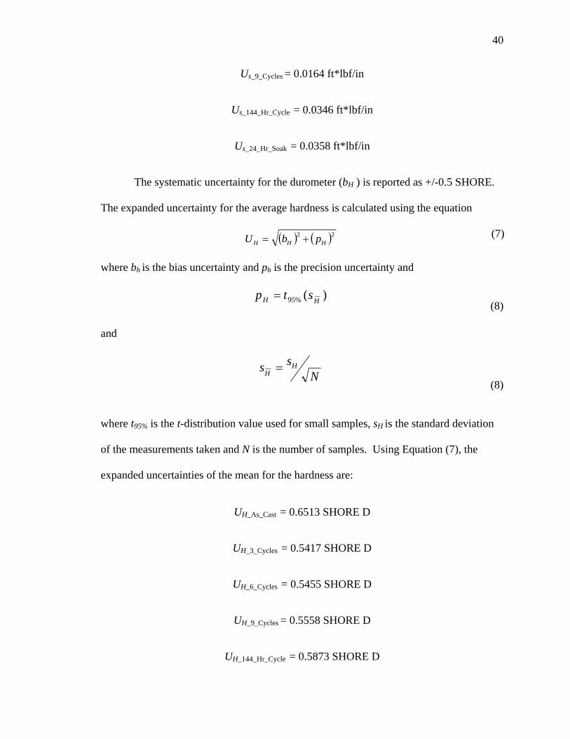
The systematic uncertainty for the durometer (bH ) is reported as +/-0.5 SHORE.
The expanded uncertainty for the average hardness is calculated using the equation
( ) ( )22HHH pbU += (7)
where bh is the bias uncertainty and ph is the precision uncertainty and
)(%95 HH stp = (8)
and
Nss H
H = (8)
where t95% is the t-distribution value used for small samples, sH is the standard deviation
of the measurements taken and N is the number of samples. Using Equation (7), the
expanded uncertainties of the mean for the hardness are:
UH_As_Cast = 0.6513 SHORE D
UH_3_Cycles = 0.5417 SHORE D
UH_6_Cycles = 0.5455 SHORE D
UH_9_Cycles = 0.5558 SHORE D
UH_144_Hr_Cycle = 0.5873 SHORE D
41
UH_24_Hr_Soak = 0.6110 SHORE D
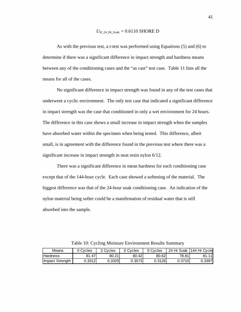
As with the previous test, a t-test was performed using Equations (5) and (6) to
determine if there was a significant difference in impact strength and hardness means
between any of the conditioning cases and the “as cast” test case. Table 11 lists all the
means for all of the cases.
No significant difference in impact strength was found in any of the test cases that
underwent a cyclic environment. The only test case that indicated a significant difference
in impact strength was the case that conditioned in only a wet environment for 24 hours.
The difference in this case shows a small increase in impact strength when the samples
have absorbed water within the specimen when being tested. This difference, albeit
small, is in agreement with the difference found in the previous test where there was a
significant increase in impact strength in neat resin nylon 6/12.
There was a significant difference in mean hardness for each conditioning case
except that of the 144-hour cycle. Each case showed a softening of the material. The
biggest difference was that of the 24-hour soak conditioning case. An indication of the
nylon material being softer could be a manifestation of residual water that is still
absorbed into the sample.
Table 10: Cycling Moisture Environment Results Summary Means 0 Cycles 3 Cycles 6 Cycles 9 Cycles 24 Hr Soak 144 Hr Cycle
Hardness 81.47 80.21 80.42 80.62 78.81 81.11Impact Strength 0.3312 0.3329 0.3573 0.3126 0.3710 0.3397

42
Summary of Results and Conclusions
A summary of the results for cycling moisture environments is found in Table 12
and average impact strength and hardness are reported in Figures 26 and 27, respectively.
It is apparent that absorbed moisture does have a significant impact on both the impact
strength and the relative hardness. Figures 28 and 29 show plots of the hardness plotted
against the impact strength for each sample and for the means of each group,
respectively.
Table 11: Summary of Results for Cycling Moisture Environments Tests 0 Cycles 3 Cycles 6 Cycles 9 Cycles 24 Hr Soak 144 Hr Cycle
Mean 81.47 80.21 80.42 80.62 78.81 81.11Stan. Dev 0.5012 0.2713 0.3048 0.3393 0.4909 0.4306Mean 0.3312 0.3329 0.3573 0.3126 0.3710 0.3397Stan. Dev 0.0167 0.0282 0.0353 0.0212 0.0500 0.0450
Hardness
Impact Strength
Figure 26: Average impact strengths for cycling moisture environment tests.
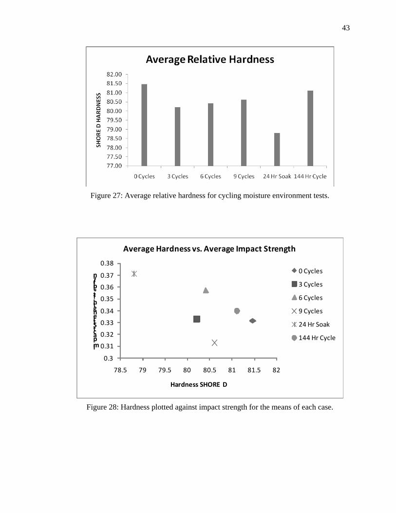
43
Figure 27: Average relative hardness for cycling moisture environment tests.
0.3
0.31
0.32
0.33
0.34
0.35
0.36
0.37
0.38
78.5 79 79.5 80 80.5 81 81.5 82
Impact Strength ft*lbf/in
Hardness SHORE D
Average Hardness vs. Average Impact Strength
0 Cycles
3 Cycles
6 Cycles
9 Cycles
24 Hr Soak
144 Hr Cycle
Figure 28: Hardness plotted against impact strength for the means of each case.
44
0.25
0.30
0.35
0.40
0.45
0.50
0.55
77.5 78.5 79.5 80.5 81.5 82.5
Impact Strength ft*lbf/in
Hardness SHORE D
Hardness vs. Impact Strength
0 Cycles
3 Cycles
6 Cycles
9 Cycles
24 Hr Soak
144 Hr Cycle
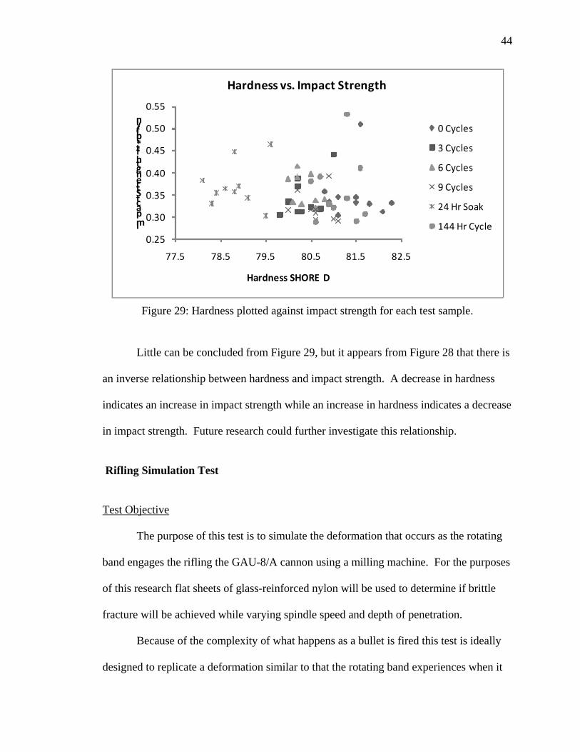
Figure 29: Hardness plotted against impact strength for each test sample.
Little can be concluded from Figure 29, but it appears from Figure 28 that there is
an inverse relationship between hardness and impact strength. A decrease in hardness
indicates an increase in impact strength while an increase in hardness indicates a decrease
in impact strength. Future research could further investigate this relationship.
Rifling Simulation Test Test Objective
The purpose of this test is to simulate the deformation that occurs as the rotating
band engages the rifling the GAU-8/A cannon using a milling machine. For the purposes
of this research flat sheets of glass-reinforced nylon will be used to determine if brittle
fracture will be achieved while varying spindle speed and depth of penetration.
Because of the complexity of what happens as a bullet is fired this test is ideally
designed to replicate a deformation similar to that the rotating band experiences when it
45
impacts the rifling in a controlled and safe environment. While conducting this test, we
will be looking for the methods that will cause brittle failure in an impact situation such
as this.
As the projectile fired in the GAU-8/A canon travels through the forcing cone of
the barrel it has an average velocity of roughly 92.5 ft/sec or for use in following
calculations, 1110 in/sec. With a forcing cone half angle of 3°, the radial velocity
component, or the velocity that the lands grow toward the central axis of the barrel and
projectile relative to the projectile, would calculate to 58.33 in/sec. This test will attempt
to replicate radial velocity components below and up to the 58.33 in/sec. As mentioned
earlier in this research, the rifling lands in the GAU-8/A barrel reach a final height of
0.007”. The radius of the rotating band found on the single band configured projectiles is
more than the 0.007” difference from the body of the projectile. With that in
consideration depths of tool penetration will range from 0.010” and 0.065” in this test.
Test Procedure
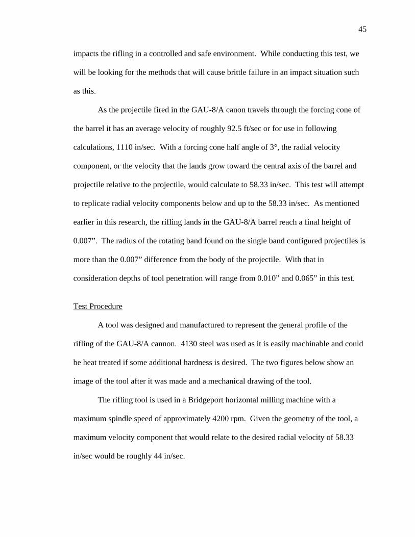
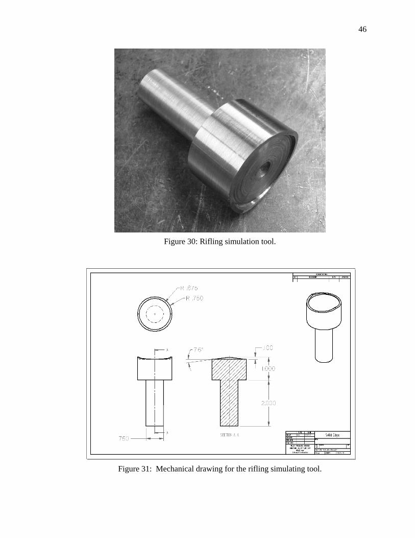
A tool was designed and manufactured to represent the general profile of the
rifling of the GAU-8/A cannon. 4130 steel was used as it is easily machinable and could
be heat treated if some additional hardness is desired. The two figures below show an
image of the tool after it was made and a mechanical drawing of the tool.
The rifling tool is used in a Bridgeport horizontal milling machine with a
maximum spindle speed of approximately 4200 rpm. Given the geometry of the tool, a
maximum velocity component that would relate to the desired radial velocity of 58.33
in/sec would be roughly 44 in/sec.
46
Figure 30: Rifling simulation tool.
Figure 31: Mechanical drawing for the rifling simulating tool.
47
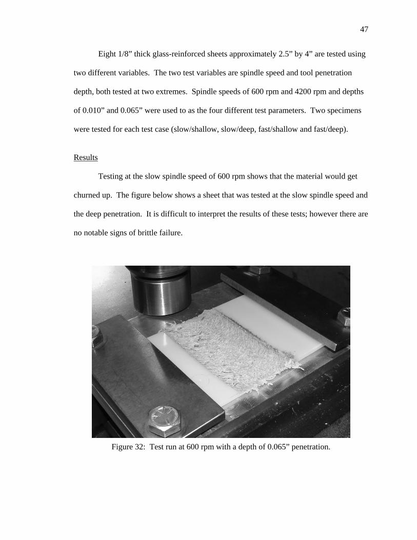
Eight 1/8” thick glass-reinforced sheets approximately 2.5” by 4” are tested using
two different variables. The two test variables are spindle speed and tool penetration
depth, both tested at two extremes. Spindle speeds of 600 rpm and 4200 rpm and depths
of 0.010” and 0.065” were used to as the four different test parameters. Two specimens
were tested for each test case (slow/shallow, slow/deep, fast/shallow and fast/deep).
Results
Testing at the slow spindle speed of 600 rpm shows that the material would get
churned up. The figure below shows a sheet that was tested at the slow spindle speed and
the deep penetration. It is difficult to interpret the results of these tests; however there are
no notable signs of brittle failure.
Figure 32: Test run at 600 rpm with a depth of 0.065” penetration.

48
When samples were tested at the high spindle speed of 4200 rpm, the sample
would melt significantly. Figure 33 shows the test specimen that was tested at the fast
spindle speed and the deep penetration depth of 0.065”.
After noticing that the higher spindle speeds resulted in melting, two samples are
also tested at a still slower spindle speed of 60 rpm. Those two samples looked very
similar to those tested at 600 rpm.
Conclusion
The results of this test are inconclusive. There are no results indicating brittle
failure. Since the test specimens melt at the high spindle speed that most closely
Figure 33: Test run at 4200 rpm and 0.065” penetration. Note that there is residual plastic material that stuck to the tool as it melted.
49
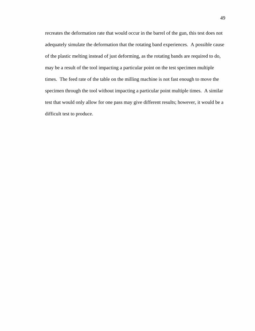
recreates the deformation rate that would occur in the barrel of the gun, this test does not
adequately simulate the deformation that the rotating band experiences. A possible cause
of the plastic melting instead of just deforming, as the rotating bands are required to do,
may be a result of the tool impacting a particular point on the test specimen multiple
times. The feed rate of the table on the milling machine is not fast enough to move the
specimen through the tool without impacting a particular point multiple times. A similar
test that would only allow for one pass may give different results; however, it would be a
difficult test to produce.
50
CONCLUSION
Previous research has indicated that absorbed moisture will increase the impact
strength of nylon materials. Our testing has confirmed those findings showing that a
significant increase in impact strength is found when both neat resin and reinforced nylon
6/12 is subjected to hydrolysis and tested while the materials still retain absorbed
moisture.
Both tests investigating the effects of moisture and temperature show that
absorbed moisture increases the impact strength of both neat resin and glass-reinforced
nylon 6/12. No significant change is seen in the impact strength for glass-reinforced
nylon samples that experienced a variety of cycled wet and dry environments with the
end of each cycle being a drying period. This seems to indicate that cycling moisture
environments will not compromise the integrity of the rotating bands. It may be possible
that increasing the number of cycles could show a change in impact strength for these
types of materials. Cycle length may also be increased in addition to increasing the
number of cycles to investigate whether longer cycle lengths have a significant effect on
impact strength. Without doing further testing however, there is no reason to believe that
the variety of temperature and moisture environments that the projectile may be in will
compromise its integrity.
There is a significant change in SHORE D hardness in all of the cases tested using
glass-reinforced nylon except that of the 144-hour cycle. This may indicate that there
was some residual moisture in the shorter cycle lengths. The higher impact strength and
the lower hardness resulting from the 24-hour soak test group indicate that an inverse
relationship between hardness and impact strength seems to exist. Further testing with
51
the changes in parameters mentioned in the previous paragraph could possibly shed more
light on this relationship and yield a meaningful test method for determining the integrity
of rotating bands.
The rifling simulation test did not adequately recreate the deformation
experienced by the rotating bands. It is possible that a similar test could be developed
that would show different results that represent the deformation of the rotating bands
better. One possibility for facilitating such a test is to use an apparatus that would
compensate for the slow feed rate of the milling machine table. This could be
accomplished by attaching a separate fixture to the table of the milling machine that
could feed the specimen at a faster rate.
Further research may look for new factors that embrittle nylon materials. Future
research could also include the increased number of cycles and increased cycle length
testing as well as some different types of testing. Should such research be pursued, I
propose that a tensile test be performed that measures the amount of plastic deformation
for a constant strain rate on samples that have been conditioned similar to those of this
research could help to investigate the amount these materials could endure for a
prescribed conditioning environment.
52
REFERENCES
[1] Price, S. J., and Hargreaves, C. R., 1981, “Metallic Projectile Body and Themoplastic Rotating Band,” Pat # 4,446,795, United States Patent, pp. 1-5. [2] Crawford, R.J., 1987, Plastics Engineering 2nd ed., Pergamon Press, New York, pp. 143, Chap 3. [3] Pillay, S., Vaidya, U. K., and Janowski, G. M., 2009, “Effects of Moisture and UV Exposure on Liquid Molded Carbon Fabirc Reinforced Nulon 6 Composite Laminates,” Composites Science and Technology, 69, pp. 839-846. [4] Miri, V., Persyn, O., Lefebvre, J. M., and Seguela, R., 2009, “Effects of Water Absorption on the Plastic Deformation Behavior of Nylon 6,” European Polymer Journal, 45, pp. 757-762. [5] Bernstein, R., Derzon, D. K., and Gillen, K. T., 2005, “Nylon 6.6 Accelerated Aging Studies: Thermal-Oxidative Degradation and Its Interaction with Hydrolysis,” Polymer Deggradation and Stabillity, 88, pp. 480-488. [6] Strong, A.B., 2008, Fundamentals of Composites, Society of Manufacturing Engineers, Dearborn, pp. 230, Chap 8. [7] Seltzer, R., Frontini, P. M., and Mai, Y., 2009, “Effect of Hygrothermal Aging on Morphology and Indentation Modulus of Injection Molded Nylon 6/organoclay Nanocomposites,” Composites Science and Technology, 69, pp. 1093-1100. [8] Nagarajan, P., and Yao, D., 2005, “Cold Forging Behavior of Smicrystalline Polymers,” Journal of Applied Polymer Science, 96, pp. 764-771. [9] Leach, D. C., and Moore, D. R., 1985, “Failure and Fracture of Short Glass Fibre-reinforced Nylon Composites,” Composites, 16, pp. 113-120. [10] Strong, A.B., 2008, Fundamentals of Composites, Society of Manufacturing Engineers, Dearborn, pp. 40, Chap 2.

53
APPENDIX
54
Figure 34: Spreadsheet data from Arrow Tech
55
56
57

58
#
Thickness behind notch (in)
Total Thickness (in)
Break Energy (ft*lb)
Impact Strength (ft*blf/in)
Chauvenet's Criterion
Expanded Uncertainty 95% (ft*lbf/in)
Impact strength hot/wet hot/dry
1 0.432 0.484 0.9256 2.142593 2.55218391 0.903714035 t 5.5498612 0.42 0.478 0.4056 0.965714 0.45087168 v 9.983423 0.427 0.485 0.5421 1.269555 0.32444269 from table 2.2284 0.429 0.471 0.453 1.055944 0.220631215 0.42 0.479 0.3688 0.878095 0.67445033 Significant Difference6 0.428 0.485 0.3894 0.909813 0.59351557 0.424 0.482 0.9879 2.91509738 0.417 0.466 0.4438 1.064269 0.1993894 hot/wet cold/wet9 0.413 0.46 0.4236 1.025666 0.29789247 t 4.997832
10 0.427 0.486 0.4142 0.970023 0.43987601 v 8.908623Std Dev 0.006001 0.009009 0.227388 0.391894 from table 2.262Mean 0.4237 0.4776 0.5354 1.142408
t95 2.306 bstrength 0.001582 Significant Difference
11 0.427 0.473 0.2694 0.630913 1.95839551 0.31194234312 0.422 0.46 0.1726 0.409005 0.27588864 hot/wet cold/dry13 0.422 0.481 t 5.47356514 0.424 0.477 0.1245 0.293632 0.59886471 v 8.07636915 0.422 0.467 0.1631 0.386493 0.10520423 from table 2.30616 0.407 0.454 0.155 0.380835 0.062309117 0.402 0.454 0.0958 0.238308 1.01832733 Significant Difference18 0.425 0.461 0.1122 0.264 0.8235345419 0.422 0.461 0.6848 2.8251775420 0.427 0.474 0.1613 0.377752 0.03892911 hot/dry cold/wet
Std Dev 0.008485 0.009624 0.182897 0.131892 t -1.75942Mean 0.42 0.4662 0.215411 0.372617 v 12.67082
t95 2.365 bstrength 0.00144 from table 2.16
21 0.431 0.482 0.2029 0.470766 0.00500663 0.222666061 No Significant Difference22 0.423 0.472 0.1992 0.470922 0.0034184123 0.419 0.465 0.1801 0.429833 0.4208735824 0.425 0.479 0.1493 0.351294 1.21880966 hot/dry cold/dry25 0.427 0.477 0.1909 0.447073 0.24572261 t -1.1173126 0.426 0.455 0.2754 0.646479 1.78019863 v 7.52500927 0.426 0.485 0.1641 0.385211 0.87421932 from table 2.30628 0.424 0.441 0.2727 0.64316 1.7464834929 0.419 0.464 0.184 0.439141 0.32630773 No Significant Difference30 0.425 0.478 0.1822 0.428706 0.43232418
Std Dev 0.003598 0.013718 0.042019 0.098427Mean 0.4245 0.4698 0.20008 0.471258 Cold/wet Cold/dry
t95 2.262 bstrength 0.00142 t 1.406253v 10.49352
31 0.426 0.474 0.1797 0.421831 0.14235413 0.06252101 from table 2.1132 0.427 0.475 0.1822 0.426698 0.0374010733 0.419 0.446 0.2029 0.484248 2.16297492 No Significant Difference34 0.431 0.481 0.1687 0.391415 1.2657320935 0.423 0.47 0.188 0.444444 0.6928554436 0.43 0.477 0.1783 0.414651 0.4075350237 0.415 0.465 0.1801 0.433976 0.3062084638 0.427 0.478 0.1736 0.406557 0.7064723739 0.421 0.472 0.2777 15.722336140 0.422 0.467 0.1719 0.407346 0.67734627
Std Dev 0.005021 0.009925 0.032168 0.027075Mean 0.4241 0.4705 0.19031 0.425685
t95 2.306 bstrength 0.001418
41 0.426 0.451 0.2626 0.616432 0.29978348 0.21799821142 0.404 0.434 0.2778 0.687624 1.2064982843 0.422 0.437 0.2069 0.490284 1.3068594644 0.424 0.442 0.228 0.537736 0.7025069345 0.426 0.444 0.2694 0.632394 0.50308462
Std Dev 0.009317 0.00658 0.030183 0.078516Mean 0.4204 0.4416 0.24894 0.592894
t95 2.776 bstrength 0.001449
As cast
Hot/Wet
Hot/Dry
Cold/Wet
Cold/Dry
Figure 35: Neat resin test results spreadsheet w/ uncertainty and t-test results
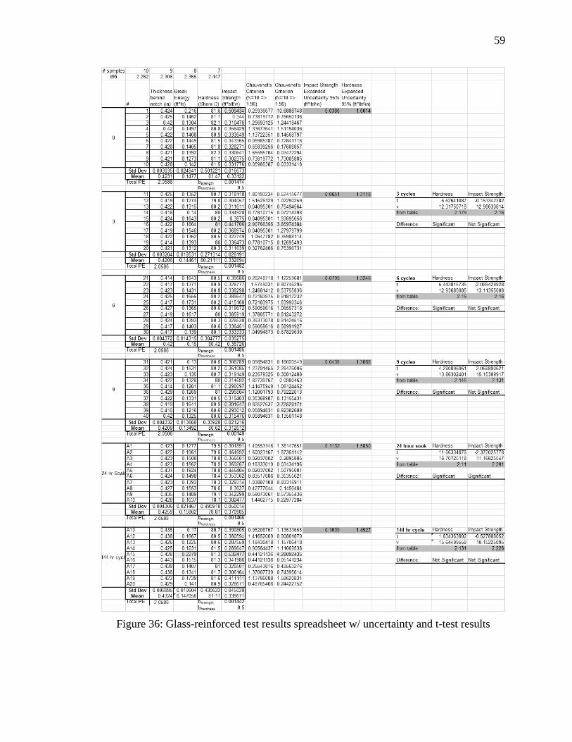
59
Figure 36: Glass-reinforced test results spreadsheet w/ uncertainty and t-test results