Embed Size (px)
Citation preview

Acta Geodyn. Geomater., Vol. 15, No. 4 (192), 329–338, 2018
DOI: 10.13168/AGG.2018.0024
journal homepage: https://www.irsm.cas.cz/acta
ORIGINAL PAPER
EFFECTS OF STRENGTH WEAKENING AND INTERFACE SLIPPING ON ROCK MASS WITH DIFFERENT DIP ANGLE STRUCTURE PLANES
Pu WANG 1, 2)*, Lishuai JIANG 3), Xiaoyu LI 3), Pengqiang ZHENG 1, 2) and Guangpeng QIN 1, 2)*
1) Department of Resources and Civil Engineering, Shandong University of Science and Technology, Tai’an, 271019, China 2)National Engineering Laboratory for Coalmine Backfilling Mining, Shandong University of Science and Technology,
Tai’an, 271019, China 3) State Key Laboratory of Mining Disaster Prevention and Control Co–founded by Shandong Province and the Ministry of Science and
Technology, Shandong University of Science and Technology, Qingdao 266590, China
*Corresponding author‘s e-mail: [email protected]; [email protected]
ABSTRACT
Micro-mechanical behaviors of rock masses with structure planes can provide informationregarding precursory characteristics of macro-fracture of strata and rock bursts. Hence,numerical simulation with uniaxial compression test is conducted using Realistic Failure ProcessAnalysis (RFPA). Then, mechanical properties and progressive failure processes for rock masseswith different dip angle structure planes are studied, and the macroscopic fractures, mechanicalresponses, and acoustic emission (AE) responses of rock masses are analyzed. Moreover, thestrength weakening and interface slipping effects with different dip angle structure planes arerevealed. The results show that rocks with different dip angle structure planes show significantstrength and interface slipping effects. A small dip angle structure plane has little influence onthe rock strength and interface slipping, which mainly manifests as failure in rock interiors. Formedium dip angle structure plane, the rock strength decreases obviously, and interface slipping isnotable along the structure plane. The effects caused by the weak plane are more prominent withrising dip angles. Compared to rocks with small dip angle structure planes, those with mediumdip angle structure planes are more easily broken. However, the total energy released and totalAE counts are smaller, indicating less serious bursting liability from rock failure.
ARTICLE INFO
Article history:
Received 27 August 2018 Accepted 12 October 2018 Available online 18 October 2018
Keywords: Structure plane Different dip angle Strength weakening effect Interface slipping effect Rock burst
Cite this article as: Wang P, Jiang L, Li X, Zheng P, Qin G: Effects of strength weakening and interface slipping on rock mass with differentdip angle structure planes. Acta Geodyn. Geomater., 15, No. 4 (192), 329–338, 2018. DOI: 10.13168/AGG.2018.0024
2016; Cao et al., 2015) were commonly performed,including tests of direct shear and triaxial stress, andbi-directional and double-sided shear friction (Wang,2012), as shown in Figure 2. However, laboratorytests have the disadvantage of tedious production andheavy work. For instance, usually a drilling machineis required to retrieve the specimens and polish them;then, the specimens must be handled according to thetest scheme. Moreover, the theoretical calculations donot accurately and intuitively reflect thecharacteristics of macroscopic rupture, mechanicalresponses, and acoustic emission (AE) responses.
Therefore, in this paper, according to the studytargets and considering the heterogeneity of rockmaterial, a numerical simulation with uniaxialcompression test using Realistic Failure ProcessAnalysis (RFPA), which obeys Weibull distributionand is usually used to effectively consider theinhomogeneity of a brittle material, is conducted.Then, mechanical properties and progressive failureprocesses for rock masses with different dip anglestructure planes are studied, and the macroscopicfracture, mechanical responses, and AE responses of
1. INTRODUCTION
Because of the joints, cracks, or faults thatuniversally occur in natural rock masses, the strengtheffect on their mechanical properties is notable.Specifically, when a fault occurs, the rock masses ontwo fault walls may slip along the fault plane, whichcan instantaneously release a large amount of elasticstrain energy, thereby inducing serious dynamicdisasters (i.e., rock bursts, shock bumps) (Jiang et al.,2018; Jiang et al., 2017). Figure 1 depicts several fieldimages of the sites after accidents. This indicates thata rock burst caused by fault occurrence is closelyrelated to the strength and interface slipping effects ofthe rock mass. Moreover, the aforementionedstructure surfaces can show significant discontinuityand inhomogeneity for the rocks, which also hasnotable effect on rock bursts (Tang et al., 2010).
Regarding the structure plane mechanicalproperties for a rock mass, laboratory tests (Cao et al.,2018; Lee et al., 2017; Day et al., 2017; Feng et al.,2017; Moayed et al., 2016; Jiang et al., 2013) ornumerical simulations (Bahaaddini et al., 2017; Wanget al., 2017; Kim et al., 2016; Bahaaddinig et al.,

P. Wang et al.
330
Fig. 1 Field images of sites captured after accidents.
s
t
t
s 3
s 1
s 1
s1
s 1
s3s 2 s 2 s s
(a) Direct shear (b) Triaxial test (c) Bidirectional friction (d) Double-sided shear friction
Fig. 2 Study methods of mechanical properties for rock mass structure plane (Reproduced with permissionfrom Wang T. 2012, Mechanism of coal bumps induced by fault reactivation. Ph.D. thesis, ChinaUniversity of Mining and Technology, Beijing, China).
When a rock mass with a structural plane isdestroyed along the weak plane, the shear stress actingon the plane (τn) should exceed its ultimate shearstress (τf) caused by the normal stress. Hence, thecritical condition of rock slipping along the weakplane can be shown in Eq. (2) based on the relation
f nτ τ= .
( )( )
3
1 3
2 tan
1 tan cot sin 2
f
f
cσ ϕσ σ
ϕ α α
⋅ +− =
− ⋅ (2)
where τf is the ultimate shear stress caused by thenormal stress, MPa. It satisfies the Mohr–Coulomb strength criterion and can be expressed by
tanf n f fcτ σ ϕ= + (Hubbert and Rubey, 1961). φf is
the internal friction angle of the fault plane, indegrees, and cf is the cohesive strength of the faultplane, MPa.
From Eq. (2), when 90α = or fα ϕ→ , the
expression ( )1 3σ σ− → ∞ is established. Hence, the
range of fault dip angles for rock breaks along thefault planes are given by Eq. (3) (Shen and Chen,2006).
rock masses are analyzed. Moreover, the strengthweakening and interface slipping effects with differentdip angle structure planes are revealed. The resultspresented here form a solid foundation for the study ofrock bursts in the vicinity of faults.
2. MECHANICAL EFFECT OF FAULT PLANE
Figure 3 depicts a fault which is described byAnderson (Cai, 2015). A mechanical model isestablished and analyzed by choosing a microunitfrom a fault plane. The length of AB as l, the normalstress, and shear stress of fault plane in the Cartesiancoordinate system can be expressed based on themechanical equilibrium, as shown in Eq. (1).
1 3 1 3
1 3
cos 22 2
sin 22
n
n
σ σ σ σσ α
σ στ α
+ − = + − =
(1)
where σn and τn are the normal and shear stresses ofthe fault plane, respectively, MPa; σ1 and σ3 are themaximum and minimum principal stresses, MPa; α isthe fault dip angle measured in degrees (°).

EFFECTS OF STRENGTH WEAKENING AND INTERFACE SLIPPING ON ROCK MASS … .
331
AC
Ba
t n
s n
x
y
s 1
s 3
s 1
s 1
s 3 s 3
a
??????
微元体Micro unit
Fault
plan
e
(a) Planar model of normal fault (b) Mechanical analysis of microbody
Fig. 3 Mechanical model of fault.
30 40 50 60 70 80 90-30
0
30
60
90
120
150
180
(s1-s
3)/M
Pa
Fault dip angle a/°
f f
s 3=0 MPa
s 3=5 MPa
s 3=10 MPa
s 3=15 MPa
s 3=20 MPa
90fϕ α< < (3)
The relationship between the fault dip angle and
its internal friction angle is obtained by finding thefirst derivative of α and equating to zero. Thus, Eq. (4)is given as follows.
452
fϕα = + (4)
The critical condition of rock failure along thefault plane (i.e., fault slipping) is obtained as shown inEq. (5), by substituting Eq. (4) into Eq. (2).
( ) ( )1 3 3min
1 sin2 tan
cosf
ff
cϕ
σ σ σ ϕϕ
−− = ⋅ + ⋅ (5)
From Eqs. (4) and (5), we can see that the criticalcondition of rock failure along a fault plane is relatedto the fault dip angle α and the confining pressure σ3.Hence, to intuitively study the problem, Eq. (5) issolved by selecting 30fϕ = and c = 0.4 MPa
(Sainoki and Mitri, 2014). Figure 4 shows therelationship among fault-slipping, fault dip angle (α),and confining stress (σ3).
As shown in Figure 4, regardless of themagnitude of confining pressure applied, the curves
are symmetrical about the straight line 452
fϕα = + in
the range of ( ),90fϕ ; moreover, the minimum value
of the principal stress difference is at the point
452
fϕα = + , which indicates that it is most likely to
slip along the fault plane. When the fault dip angle isclose to φf or 90°, the principal stress difference tendsto infinity; however, if it reaches or exceeds itscorresponding ultimate failure strength, the rock willno longer slip along the fault plane, but will bedestroyed from inside.
Fig. 4 Relationship among fault-slipping, fault dipangle (α), and confining stress (σ3).
3. NUMERICAL ANALYSIS OF EFFECTS ON
STRENGTH AND INTERFACE SLIPPING FOR ROCK MASS
3.1. ESTABLISHMENT OF RFPA MODEL
Considering the rock heterogeneity, rock modelswith different dip angle structure planes areestablished using RFPA numerical software.According to the analysis in Section 2, regardless ofthe amount of confining pressure applied, therelationship between fault slipping and fault dip angleis consistent; hence, in this section, the relationshipwith no confining pressure (i.e., σ3 = 0 MPa) is chosenand studied. Then, the macroscopic fractureappearance, mechanical responses, and AE responsesof the rock specimen are simulated and analyzed bythe uniaxial compression displacement loadingmethod.
The lithology of rock specimen is selected assandstone, and the preset structure plane is in themiddle of the specimen, running through the wholerock. The size of the specimen is designed to be

P. Wang et al.
332
Table 1 Mechanical parameters of coal and rocks (Zhao et al., 2013).
Media Type Modulus of elasticity (MPa)
Average strength (MPa)
Poisson ratio Homogeneity index
Sandstone 13500 40 0.22 2.5 Structure plane 2000 18 0.3 2
3.2. RESULTS OF RFPA SIMULATION
3.2.1. FAILURE PROCESS OF ROCK MASS WITHDIFFERENT DIP ANGLE STRUCTURE PLANES
The uniaxial compression tests of rockspecimens with different dip angle structure planesand the intact specimen without a preset structureplane in Figure 5 are carried out. The failure processof the specimens is shown in Tables 2–4. The failurepatterns of rock specimens with different dip anglestructure planes are different.
As shown in Table 2, regarding the intact rockspecimen, at the 20th step, the upper part of thespecimen presents obvious instability units, while thelower part is relatively unobvious. At 31 steps, thenumber of instability units rises notably and witha random distribution; moreover, they spreadthroughout the whole rock, but no cracks are formed.At the 37th step, the instability units continue toincrease and interconnect, and then many localmicrocracks occur. At the 40th step, microcracksexpand significantly, while the concentrated stress atthe crack tip further causes the crack to expand,thereby interconnecting and forming an obviousmacroscopic fracture; then, the rock specimen may bedestroyed along the fracture plane.
In Table 3, when the rock specimen has a smalldip angle (i.e., 10°, 20°, and 30°) of the preset fractureplane, its failure process is similar to that of the intactrock specimen. At the initial loading stage, with thecompacting of the structure plane having a certainwidth, prominent instability units only occur in theupper part of rock and near the weak plane, while thelower part of rock has no instability units. Withcontinuous loading, the failure process is same as thatof the intact specimen. This indicates that the interface
Rock block
Rock block
Fault dip angle
Structu
re pla
ne
Displacement loading
100mm
50mm
50mm
50mm
Fig. 5 Calculation model of RFPA.
50 mm (width) ×100 mm (height), and the divisionunits are 50 × 100=5000. Considering the symmetryanalysis of fault slipping in section 2 and the modelsizes, the dip angle of structure plane is preset to 10°,20°, 30°, 40°, 50°, and 60°, and its width is set to1 mm. The model calculation adopts the plane stressmodel and uniaxial compression axial displacementloading. Figure 5 shows the calculation model ofRFPA. The initial displacement value applied on themodel sets to 0.002 mm, and the displacementincrement at each loading-step is 0.003 mm, until it isdestroyed. The mechanical parameters of the mesounit of the rock are shown in Table 1 (Zhao et al.,2013; Ma et al., 2007).
Table 2 Loading test of intact rock.
Specimen Failure process
Intact rock specimen
Step 20
Step 31
Step 37
Step 40
Step 45

EFFECTS OF STRENGTH WEAKENING AND INTERFACE SLIPPING ON ROCK MASS … .
333
Table 3 Loading tests of rock with small dip angle structure planes (10°, 20°, and 30°).
Specimens Failure process
Rock specimen with a structure
plane of 10°
Step 20
Step 32
Step 38
Step 42
Step 45
Rock specimen with a structure
plane of 20°
Step 20
Step 31
Step 37
Step 41
Step 50
Rock specimen with a structure
plane of 30°
Step 22
Step 34
Step 38
Step 42
Step 46
3.2.2. STRESS–STRAIN CHARACTERISTIC OF ROCK MASS WITH DIFFERENT DIP ANGLE STRUCTURE PLANES
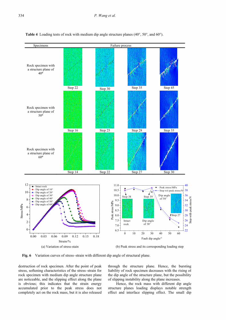
As shown in Figure 6, at the initial loading stage,rock specimens with different dip angles arecompacted, and the stress–strain curves coincide,showing a high degree of consistency. When the peakload is reached, the peak stress of intact rockspecimen is 10.69 MPa, while that of with small dipangle structure planes (that is less than 30°) is in therange of 10.35–10.60 MPa. Moreover, the loadingsteps with the rock failure have little difference, whichindicates that the small dip angle structure planes haslittle effect on the strength of rock specimens. Withthe rise in the dip angle of structure plane, the slippingeffect of the plane gradually increases, and thestrength of the rock specimen is significantly reduced.For instance, the peak stress with a dip angle of 40° is8.60 MPa, which is much less than that of a dip angleof 30° (i.e., 10.35 MPa); moreover, with the rising dipangle, the failure strength of the rock specimen with50° and 60° is 7.58 MPa and 6.85 MPa, respectively.
As the dip angle of the structure plane increases,the total strain prior to the peak stress decreases, andthe total strain energy decreases, resulting in thereduction of bursting liability caused by internal
slipping effect of rock specimen with small dip anglestructure planes is not obvious.
As shown in Table 4, when the rock specimenhas a medium dip angle (i.e., 40°, 50°, and 60°) of thepreset fracture plane, the failure of the rock block doesnot occur anymore on both sides of the plane, but it isprominently slipping along the plane. For instance,when the rock specimen has a structure plane with dipangle of 50°, at the 16th step, many instability unitsoccur near the weak plane and in the upper part ofrock. At the 25th step, instability units rise notablyand the microfracture plane at the preset plane isformed; however, microcracks are not formed in thetwo sides of the rock. At the 28th step, the cracks atthe preset plane extend into a macrofracture plane, andthe macrocracks still not occur in the two sides of therock. At the 35th step, slipping failure of rockspecimen occurs along the macro failure plane at thepreset plane. This indicates that the interface slippingeffect of rock specimen with medium dip anglestructure planes is notable. Moreover, as the dip angleof the structure plane increases, the slipping failureoccurs more easily (i.e., loading steps are 45, 35, and30 in turn), which shows that the slipping effect isenhanced with the dip angle of structure planesincreasing.
P. Wang et al.
334
Table 4 Loading tests of rock with medium dip angle structure planes (40°, 50°, and 60°).
Specimens Failure process
Rock specimen with a structure plane of
40°
Step 22
Step 30
Step 35
Step 45
Rock specimen with a structure plane of
50°
Step 16
Step 25
Step 28
Step 35
Rock specimen with a structure plane of
60°
Step 14
Step 22
Step 27
Step 30
0 10 20 30 40 50 606.5
7.0
7.5
8.0
8.5
9.0
9.5
10.0
10.5
11.0 Peak stress/MPa Step wit peak stress/N
Fault dip angle/°
Peak
str
ess/
MPa
22
24
26
28
30
32
34
36
38
40
Ste
p w
ith p
eak
stre
ss/N
Intact rock
Step 38
Dip angle of 30°
Step 39
Step 27
Dip angle of 50°
0.00 0.03 0.06 0.09 0.12 0.15 0.18
0
2
4
6
8
10
12
Str
ess/
MP
a
Strain/%
Intact rock Dip angle of 10° Dip angle of 20° Dip angle of 30° Dip angle of 40° Dip angle of 50° Dip angle of 60°
(b) Peak stress and its corresponding loading step (a) Variation of stress-stain
Fig. 6 Variation curves of stress–strain with different dip angle of structural plane.
through the structure plane. Hence, the burstingliability of rock specimen decreases with the rising ofthe dip angle of the structure plane, but the possibilityof slipping instability along the plane increases.
Hence, the rock mass with different dip anglestructure planes loading displays notable strengtheffect and interface slipping effect. The small dip
destruction of rock specimen. After the point of peakstress, softening characteristics of the stress–strain forrock specimen with medium dip angle structure planeare noticeable, and the slipping effect along the planeis obvious; this indicates that the strain energyaccumulated prior to the peak stress does notcompletely act on the rock mass, but it is also released

EFFECTS OF STRENGTH WEAKENING AND INTERFACE SLIPPING ON ROCK MASS … .
335
Table 5 AE Evolution of typical rock specimens.
Specimens AE evolution
Intact rock specimen
Step 11
Step 16
Step 33
Step 38
Step 44
Rock specimen
with structure plane of 20°
Step 11
Step 16
Step 30
Step 37
Step 45
Rock specimen
with structure plane of 50°
Step 9
Step 13
Step 20
Step 28
Step 34
temporal-spatial distribution and evolution of AEsignals are obtained, as shown in Table 5. Amongthem, the circle diameter represents the AE intensity,the white circles are the AE signals generated by thecompression shear failure, and the red circles are theAE signals produced by the tensile failure (Zhang andLi, 2017).
As shown in Table 5, when the rock specimenhas a structure plane with dip angle of 20°, at the 11thstep, many AE signals occur randomly in the upperpart of the rock specimen while only a few of them inthe lower part; at the 16th step, AE signals increaseobviously and spread in the whole rock, but they arestill randomly distributed; at the 30th step, the AEsignals begin to develop orderly, and multiple AEaccumulating points occur in the upper part of rock.Then, AE accumulation is more obvious at 37 steps,which indicates large amount strain energy releases; atthe 45th step, the AE signals are mainly accumulatednear the fracture plane caused by cracksinterconnection, and the rock specimen undergoesfailure. As to the rock specimen having a structureplane with dip angle of 50°, at the 9th step, many AEsignals accumulate on the local structure plane,forming a AE accumulating zone at 13 steps; at the
angle structure plane has little effect on the rockstrength, and the interface slipping effect is notobvious, which mainly manifests as failure in theinterior of rock. Meanwhile, the rock strength withmedium dip angle structure plane is decreasedprominently, and the interface slipping effect isnotable, which is easy to slip along the structureplane; moreover, the strength weakening effect andthe interface slipping effect are more obvious with theincreasing of dip angle. The result agrees with theanalysis results of the relationship between the faultslipping and fault dip angle with σ3 = 0 MPa inSection 2.
3.2.3. AE GENERATION OF ROCK MASS WITH
DIFFERENT DIP ANGLE STRUCTURE PLANES
As a typical brittle material, rock can accumulatea large amount of elastic strain energy before failure,and this energy will be released in elastic wave modeand will create AE signals when the rock is destroyed.According to the aforementioned analysis, typicalrock specimens, including an intact rock specimen,a rock specimen with small dip angle structure plane(20°), and a rock specimen with medium dip anglestructure plane (50°), are chosen, and then the
P. Wang et al.
336
0.00 0.02 0.04 0.06 0.08 0.10 0.12 0.14 0.16 0.18
0
2
4
6
8
10 Stress/MPa Release energy/J
Strain/%
Stre
ss/M
Pa
0.00
0.05
0.10
0.15
0.20
0.25
0.30
Rel
ease
ene
rgy
of A
E/J
0.00 0.02 0.04 0.06 0.08 0.10 0.12 0.14 0.16 0.18
0
2
4
6
8
10
Stress/MPa AE counts/N AE total counts/N
Strain/%
0
100
200
300
400
500
600
700
800
0
1000
2000
3000
4000
50005000
0
0
0
4000
3000
2000
1000
0.00 0.02 0.04 0.06 0.08 0.10 0.12 0.14 0.16 0.18
0
1
2
3
4
5
6
7
8 Stress/MPa Release energy/J
Strain/%
Stre
ss/M
Pa
0.00
0.01
0.02
0.03
0.04
0.05
0.06
0.07
0.08
Rel
ease
ene
rgy
of A
E/J
0.00 0.02 0.04 0.06 0.08 0.10 0.12 0.14 0.16 0.18
0
1
2
3
4
5
6
7
8
Stress/MPa AE counts/N AE total counts/N
Strain/%
020406080100120140160180200220
0
200
400
600
800
1000
12000Block collapse
Step 48
0
1200
1000
(a) Stress–strain curve and AE energy distribution (b) Stress–strain curve and AE counts
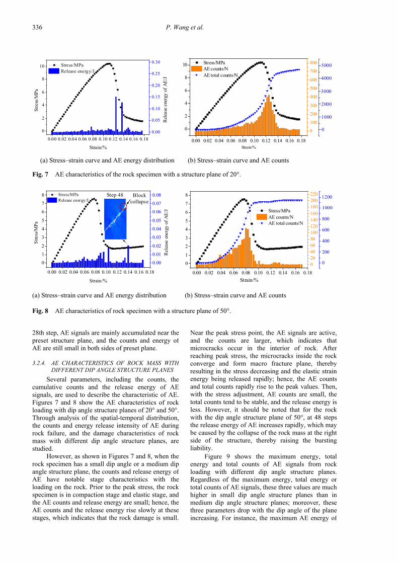
Fig. 7 AE characteristics of the rock specimen with a structure plane of 20°.
(a) Stress–strain curve and AE energy distribution (b) Stress–strain curve and AE counts
Fig. 8 AE characteristics of rock specimen with a structure plane of 50°.
Near the peak stress point, the AE signals are active,and the counts are larger, which indicates thatmicrocracks occur in the interior of rock. Afterreaching peak stress, the microcracks inside the rockconverge and form macro fracture plane, therebyresulting in the stress decreasing and the elastic strainenergy being released rapidly; hence, the AE countsand total counts rapidly rise to the peak values. Then,with the stress adjustment, AE counts are small, thetotal counts tend to be stable, and the release energy isless. However, it should be noted that for the rockwith the dip angle structure plane of 50°, at 48 stepsthe release energy of AE increases rapidly, which maybe caused by the collapse of the rock mass at the rightside of the structure, thereby raising the burstingliability.
Figure 9 shows the maximum energy, totalenergy and total counts of AE signals from rockloading with different dip angle structure planes.Regardless of the maximum energy, total energy ortotal counts of AE signals, these three values are muchhigher in small dip angle structure planes than inmedium dip angle structure planes; moreover, thesethree parameters drop with the dip angle of the planeincreasing. For instance, the maximum AE energy of
28th step, AE signals are mainly accumulated near thepreset structure plane, and the counts and energy ofAE are still small in both sides of preset plane.
3.2.4. AE CHARACTERISTICS OF ROCK MASS WITH
DIFFERENT DIP ANGLE STRUCTURE PLANES
Several parameters, including the counts, thecumulative counts and the release energy of AEsignals, are used to describe the characteristic of AE.Figures 7 and 8 show the AE characteristics of rockloading with dip angle structure planes of 20° and 50°.Through analysis of the spatial-temporal distribution,the counts and energy release intensity of AE duringrock failure, and the damage characteristics of rockmass with different dip angle structure planes, arestudied.
However, as shown in Figures 7 and 8, when therock specimen has a small dip angle or a medium dipangle structure plane, the counts and release energy ofAE have notable stage characteristics with theloading on the rock. Prior to the peak stress, the rockspecimen is in compaction stage and elastic stage, andthe AE counts and release energy are small; hence, theAE counts and the release energy rise slowly at thesestages, which indicates that the rock damage is small.

EFFECTS OF STRENGTH WEAKENING AND INTERFACE SLIPPING ON ROCK MASS … .
337
the rock with small dip angle structure plane, therock with medium dip angle structural plane ismore easily to be broken and its failure steps areless; however, the release total energy and totalAE counts are smaller, which indicates that therock burst caused by rock failure may be lessserious. Studying the micromechanical behaviors of rock
mass with a structure plane can provide the basis forthe precursory characteristics of macro-fracture andlay a solid foundation for the study of the rock burstsnear faults.
ACKNOWLEDGMENTS
The study was funded by the NationalNatural Science Foundation of China (nos.51574155, 51504145, 51804182, and 51704182),Natural Science Foundation of Shandong Province(no. ZR2017BEE050), Scientific Research Foundationof Shandong University of Science and Technologyfor Recruited Talents (no. 2015RCJJ057), ShandongProvinciál Key R & D Plan (Public Welfare SpecialProgram) of China (no. 2017GGX20125), andShandong Provincial Institute of Science andTechnology Plan (no. J17KB041).
REFERENCES
Bahaaddini, M.: 2017, Effect of boundary condition on theshear behaviour of rock joints in the direct shear test.Rock Mech. Rock Eng., 50, 5, 1141–1155. DOI: 10.1007/s00603-016-1157-z
Bahaaddini, M, Hagan, P.C., Mitra, R. and Khosravi, M.H.:2016, Experimental and numerical study of asperitydegradation in the direct shear test. Eng. Geol., 204,41–52. DOI: 10.1016/j.enggeo.2016.01.018
Cai, W.: 2015. Fault rockburst induced by static anddynamic loads superposition and its monitoring andwarning, Ph.D. thesis, China University of Mining andTechnology, Xuzhou, China, 20pp.
Cao, P., Zhong, Y.F., Li, Y.J. and Liu, J.: 2015,Investigations on direct shear tests and PFC2Dnumerical simulations of rock-like materials with ahole and prefabricated cracks. Key Eng. Mater., 627,477–480. DOI: 10.4028/www.scientific.net/KEM.627.477
Cao, R.H., Lin, H. and Cao, P.: 2018, Strength and failurecharacteristics of brittle jointed rock-like specimensunder uniaxial compression: digital speckletechnology and a particle mechanics approach. Int. J.Min. Sci. Technol., 28, No. 4, 669–677. DOI: 10.1016/j.ijmst.2018.02.002
Day, J.J., Diederichs, M.S. and Hutchinson, D.J.: 2017, Newdirect shear testing protocols and analyses forfractures and healed intrablock rockmassdiscontinuities. Eng. Geol., 229, 53–72. DOI: 10.1016/j.enggeo.2017.08.027
Feng, X.T., Zhang, X.W., Yang, C.X., Kong, R., Liu, X.Y.and Peng, S.: 2017, Evaluation and reduction of theend friction effect in true triaxial tests on hard rocks.Int. J. Rock Mech. Min. Sci., 97, 144–148. DOI: 10.1016/j.ijrmms.2017.04.002
Hubbert, M.K. and Rubey, W.W.: 1961, Role of fluidpressure in mechanics of overthrust faulting. Geol.
10 20 30 40 50 600.0
0.2
0.4
0.6
0.8
1.0
AE total counts/N
Rel
ease
ene
rgy
of A
E/J
Dip angle of structure plane/°
Maximum release energy/J Total release energy/J
0
1000
2000
3000
4000
5000
6000
AE
tota
l cou
nts/
N
Fig. 9 Energy and total counts of AE with differentdip angle structure plane.
rock with small dip angle structure plane is in therange of 0.097 J–0.152 J, while that of with mediumdip angle structure plane falls within 0.017 J–0.065 J.The total AE count number of rock with small dipangle structure plane is about 5000, while that of withmedium dip angle structure plane is 1044–1850, muchless than the former. Hence, it can be concluded thatrock burst caused by internal failure with small dipangle structure plane is much more serious than thatof with medium dip angle structure plane, where therock easily slips along the preset plane.
4. CONCLUSIONS
In this study, using mechanical analysis andnumerical simulation, the strength weakening andinterface slipping effects of rock masses with differentdip angle structure planes are studied and revealed.We can obtain several conclusions as follows.
• The rock with a different dip angle structure planeshows a significant strength effect. The strengthof rock with small dip angle structure plane isalmost the same as that of intact rock, whichindicates that the small dip angle structure haslittle effect on rock strength; on the other hand,the strength of rock with medium dip anglestructure drops notably, and the strengthweakening effect is more significant with a risingdip angle.
• The rock with a different dip angle structure planeshows a notable interface slipping effect. Theinterface slipping effect of rock with small dipangle structure is not obvious, and mainlymanifests as failure inside the rock; meanwhile,the effect for a medium dip angle structure isnotable and will be enhance with the dip anglerising, which is easy to slip along the structureplane.
• The bursting liability of rock with different dipangle structure planes is different. Compared to

P. Wang et al.
338
Shen, M.R. and Chen, J.F.: 2006, Rock mechanics, TongjiUniversity Press Shanghai, 78 pp.
Tang, C.A., Wang, J.M. and Zhang, J.J.: 2010, Preliminaryengineering application of microseismic monitoringtechnique to rockburst prediction in tunneling ofJinping II project. Rock Mech. Geotech. Eng., 2, No.3, 193–208. DOI: https://doi.org/10.3724/SP.J.1235.2010.00193
Wang, P., Jiang, L. S., Jiang, J. Q., Zheng, P. Q. and Li, W.:2018, Strata behaviors and rock burst–inducingmechanism under the coupling effect of a hard, thickstratum and a normal fault. International Int. J.Geomech, 18, No. 2, 04017135. DOI:10.1061/(ASCE)GM.1943-5622.0001044
Wang, Y.J., Niu, H.P., and Duan, D.: 2017, RFPA2Dnumerical simulation of carbonaceous mudstone underuniaxial compression. Coal Technology, 36, No. 7,50–51. DOI:10.13301/j.cnki.ct.2017.07.019
Wang, T.: 2012, Mechanism of coal bumps induced by faultreactivation. Ph.D. thesis, China University of Miningand Technology, Beijing, China.
Zhao, S.K., Zhang, Y., Han, R.J., Jiang, H.B., Zhang, N.B.and Xu, Z.J.: 2013, Numerical simulation experimentson bursting liability evolution of compound coal-rockstructure. J. Liaoning Univ. Nat. Sci., 32, No. 11,1441–1446. DOI: 10.3969/j.issn.1008-0562.2013.11.001
Zhang, J.W. and Li, Y.L.: 2017, Ultrasonic vibrations andcoal permeability: Laboratory experimentalinvestigations and numerical simulations. InternationalInt. J. Min. Sci. Technol, 27, No. 2, 221–228. DOI: https://doi.org/10.1016/j.ijmst.2017.01.001
Soc. Am. Bull., 70, 5, 115. DOI: 10.1130/0016-7606(1959)70[167:ROFPIM]2.0.CO;2
Lee, S., Chang, I., Chung, M.K., Kim, Y.Y. and Kee, J.:2017, Geotechnical shear behavior of Xanthan Gumbiopolymer treated sand from direct shear testing.Geomech. Eng., 12, 5, 831–847. DOI: 10.12989/gae.2017.12.5.831
Jiang, J.Q., Wang, P., Jiang, J.S., Zheng, P.Q. and Feng, F.:2018, Numerical simulation on mining effectinfluenced by a normal fault and its induced effect onrock burst. Geomech. Eng., 14, 4, 337–344. DOI: 10.12989/gae.2018.14.4.337
Jiang, L. S., Wang, P., Zhang, P.P., Zheng, P.P. and Xu, B.:2017, Numerical analysis of the effects induced bynormal faults and dip angles on rock bursts. CRMecanique, 345, 10, 690–705. DOI: 10.1016/j.crme.2017.06.009
Jiang, Y.D., Wang, T., Song, Y.M., Wang, X. and Zhang,W.: 2013, Experimental study on the stick-slip processof coal-rock composite samples. J. China Coal Soc.,38, 2, 177–182. DOI:10.13225/j.cnki.jccs.2013.02.013
Kim, B.S., Kato, S., Park, S.W. and Takeshita, Y.: 2016,DEM simulation on opening between shear boxes indirect shear test. Japanese Geotech. J., 11, 1, 21–31.DOI: https://doi.org/10.3208/jgs.11.21
Ma, Y., Jing, H.W. and Chen, Y.H.: 2007, Numericalsimulation of failure mechanism of surrounding rocksin mining induced roadway and its support. J. Min.Saf. Eng., 24, 1, 109–113.
Moayed, R.Z., Alibolandi, M. and Alizadeh, A.: 2016,Specimen size effects on direct shear test of siltysands. Int. J. Geotech. Eng., 11, 2, 198–205. DOI: 10.1080/19386362.2016.1205166
Sainoki, A. and Mitri, H.S.: 2014, Evaluation of fault-slippotential due to shearing of fault asperities. Can.Geotech. J., 52, 10, 1417–1425. DOI: 10.1139/cgj-2014-0375