Embed Size (px)
Citation preview

Effects of Steel Fibre Reinforcement on the Behaviour of Headed Stud Shear Connectors for Composite Steel-Concrete Beams 72
EFFECTS OF STEEL FIBRE REINFORCEMENT ON THE BEHAVIOUR OF HEADED STUD SHEAR CONNECTORS
FOR COMPOSITE STEEL-CONCRETE BEAMS
O.Mirza1 and B.Uy 2, *
1 PhD Candidate, School of Engineering, University of Western Sydney, Australia Telephone: + 612 4736 0402, Fax: +612 4736 0137, Email: [email protected]
2 Professor and Head of School of Engineering, University of Western Sydney, Australia Telephone: + 612 4736 0228, Fax: +612 4736 0137 *(Corresponding author: Email: [email protected])
Locked Bag 1797 Penrith South DC, NSW 1797, Australia
Received: 31 October 2007; Revised: 10 January 2008; Accepted: 16 January 2008
ABSTRACT: Composite steel-concrete beams are becoming increasingly popular in multistorey buildings due to their higher span/depth ratio, reduced deflections and increased stiffness value. However, their performance is highly dependent on the load-slip characteristics of the shear connectors. More recently, trapezoidal profiled slabs are becoming increasingly more popular for high rise buildings when compared with solid slabs because they can achieve large spans with little or no propping and they require less concrete and plywood formwork. However, the profiles used to achieve these savings can have a detrimental effect on the shear connector behaviour. This paper describes a nonlinear finite element model developed using ABAQUS to study the behaviour of shear connectors in both solid and profiled steel sheeting slabs. In addition to analysing the influence of the shear connectors on the structural performance, steel fibres are introduced to further augment the ductility and strength of the shear connection region in the slab. The results obtained from the finite element analyses were verified against experimental results and indicate that the strength and load-slip behaviour are significantly influenced by the inclusion of steel fibres.
Keywords: Composite steel-concrete beams; steel fibres; finite element analysis
1. INTRODUCTION Martin [1] stated that currently, composite structures have been commonly used in construction in order to save time in construction and subsequently reduce structural costs. Composite beam designs are greatly affected by the behaviour of the shear connection. The main factors affecting shear connection are the strength of the shear connectors and the strength of the concrete that surrounds the shear connectors. In the 1960’s, composite beams used welded wire fabric (WWF) as secondary reinforcement for temperature and shrinkage in the concrete. The apparent problems that arose were the correct positioning of the WWF and the cost of labour and time. One improvement to the existing concept is with the application of steel fibres. Steel fibres are preferred to steel reinforcement/mesh because they reduce dead loads; subsequently they reduce the load transferred to the foundations and at the same time improve the moment capacity, fire resistance and control cracking. A three dimensional finite element model has been developed by Lam and El-Lobody [2] to simulate the behaviour of shear connectors in composite steel-concrete beams for solid slabs. The finite element results compared well with the experimental results and all the modes of failure were accurately predicted by the finite element model. Kim et al. [3] studied the behaviour of shear connection for composite steel and concrete beams using experimental studies and the results were compared using a two dimensional finite element analysis using the LUSAS finite element programme. The authors concluded that the inclusion of profiled steel sheeting led to an increase in strength and the finite element result and experimental results were in good agreement. Furthermore the authors also showed that the behaviour of shear connection in composite
Advanced Steel Construction Vol. 5, No. 1, pp. 72-95 (2009)
The Hong Kong Institute of Steel Construction www.hkisc.org

73 O.Mirza and B.Uy
steel-concrete beams is greatly influenced by the loading and boundary conditions. More advanced finite element analysis was performed by El-Lobody and Young [4] to describe the structural performance of shear connectors in composite steel-concrete beams with profiled slabs. A three dimensional nonlinear finite element analysis was used to compare the experimental results and it was concluded that the capacity of shear connection, load-slip behaviour and failure modes predicted were in good correlation with the experimental results. Previously, experimental push tests have been used to evaluate the shear connector capacity, and in this paper the load versus slip relationship of the connectors was compared against a three dimensional finite element model developed using a finite element software package known as ABAQUS. The main objectives of this paper are to develop a three dimensional finite element model to simulate the shear connector behaviour for both solid and profiled slabs with the addition of steel fibres into the concrete slab for the push test and to determine the advantages related to the finite element analysis of push tests. 2. ADVANTAGES OF FIBRES TO SHEAR CONNECTOR BEHAVIOUR AND
STRENGTH Lam and Nip [5] performed horizontal push off tests on six composite beams. The parameters considered were transverse reinforcement and steel fibres. The push off specimens consisted of four 600 mm wide hollow core units connected to a 254 x 254 x 73 universal column with six 19 mm diameter x 100 mm height pre-welded headed shear studs at 150 mm centres. Four 1100 mm long transverse bars were placed in the opened cores and in-situ concrete was placed and compacted in the central gap. Lam and Nip’s experiments showed that by adding 2 % of steel fibres, both the compressive and flexural strength increased by 25 and 20 %, respectively. Shear stud failure occurred where transverse bars of T16 specification were used. Concrete with steel fibres were observed to have a higher ultimate load than their counterparts. Meanwhile, there was greater slip ductility where the increment was up to 75 % and the shear capacity was at 16 % increment. Craig et al. [6] compared the behaviour of composite steel-concrete beams using steel fibres and conventional reinforcement. The authors established that the composite steel-concrete with steel fibres could sustain higher loads than plain concrete. When steel fibre reinforcement was added to the concrete, the concrete exhibited improved confinement and better bond. Moreover, steel fibres also enhanced the rotational and moment capacity. The combination of steel fibres with a composite slab not only increases structural stiffness and ductility, they also provide slabs with a fire rating ranging from 60 to 90 minutes. Two aspects are to be considered when steel fibre reinforced concrete is used in composite beams; shear stud resistance and ductility and the ability of steel fibre reinforced concrete to resist transverse shear in the slabs adjacent to the shear studs, Robery [7]. Roberts-Wollmann et al. [8] used steel fibres to replace welded wire fabric (WWF) as secondary reinforcement and verified that both deflection and cracks decreased in composite beams. They also demonstrated that it was preferable to use steel fibres rather than synthetic fibres. A slab reinforced with 29.6 kg/m3 of steel fibres had a higher ultimate strength (18 %) than a slab reinforced with WWF. Using steel fibres also resulted in a higher ultimate capacity. The researchers also showed that the composite beam reinforced with 0.9 kg/m3 of synthetic fibres failed at a load equivalent to the WWF.

Effects of Steel Fibre Reinforcement on the Behaviour of Headed Stud Shear Connectors for Composite Steel-Concrete Beams 74
3. EXPERIMENTAL INVESTIGATION 3.1 Description of Push Test Specimens Two types of experimental investigations were considered for comparison with the finite element models developed in this paper. They include Becher [9] for solid slabs and Wu [10] for profiled slabs. All experimental tests were based on Eurocode 4, British Standards Institution [11] where a push test specimen consists of a steel beam connected to two concrete slabs, either a solid slab or profiled slab through shear connectors. The concrete slabs were embedded in mortar or gypsum onto the test bed and a uniformly distributed load was applied onto the upper end of the web of the steel beam. However, some compromise has been made due to time limits, equipment and budget restrictions. The modified push test, as shown in Figures 1 and 2 involve a standard push test as described with a roller support at one end to eliminate any horizontal resistance being imposed on the slab. The slab dimensions were 600 mm x 600 mm x 120 mm; 50 mm shorter and 30 mm thinner than that suggested by Eurocode 4, British Standards Institution [11]. In order to provide identical lateral and longitudinal reinforcement strength, 4 x 4 reinforcing mesh bar was used as a substitute for 5 x 4 reinforcing mesh which was outlined in Eurocode 4, British Standards Institution [11]. The steel beam used was a 200UB25. Each specimen was initially loaded to 40 % of the expected failure load then cycled 25 times between 5 % and 40 % of the expected failure load. Finally, each specimen was loaded until failure occurred. Twelve push tests were carried out to determine the load-slip behaviour of the shear connectors for both the solid slab and profiled slab configurations. Three specimens of different steel fibre reinforcement concentrations with two push tests each were tested, as illustrated in Table 1.
4 x 4 reinforcing mesh are provided in both ways with 10 mm diameter
reinforcing bars with 180 mm spacing.
Figure 1. Details of Push Test Specimen for Solid Slab

75 O.Mirza and B.Uy
4 x 4 reinforcing mesh are provided in both ways with 10 mm diameter
reinforcing bars with 180 mm spacing.
Figure 2. Details of Push Test Specimen for Profiled Slab
Table 1. Beam parameters
Test No. Slab Profile Percentage of steel fibres
1 Solid slab 0.0
2 Solid slab 0.3
3 Solid slab 0.6
4 Lysaght W-Dek Profiled slab 0.0
5 Lysaght W-Dek Profiled slab 0.3
6 Lysaght W-Dek Profiled slab 0.6
4. FINITE ELEMENT MODEL 4.1 General The finite element program ABAQUS, Karlsson and Sonrensen [12], [13] and [14] was used to quantify the behaviour of the shear connection in composite beams. The main components affecting the behaviour of the shear connection in composite beams were the concrete slab, steel beam, profiled steel sheeting, reinforcing bars and shear connectors. These components must be carefully modelled to obtain an accurate result from the finite element analysis. A three dimensional finite element model has been developed to simulate the geometric and material nonlinear behaviour of composite beams. The accuracy of the analysis is heavily dependent on the constitutive laws used to define the mechanical behaviour.

Effects of Steel Fibre Reinforcement on the Behaviour of Headed Stud Shear Connectors for Composite Steel-Concrete Beams 76
4.2 Concrete 4.2.1 Plain concrete To model the nonlinear behaviour of the concrete slab, plain concrete was recommended by Carreira and Chu [15], where the stress in compression is linear up to a stress of 0.4f ’c. Beyond this point, it is in the plastic region. The ratio of biaxial compressive stress and uniaxial compressive stress based on Liang et al. [16] was taken to be 1.16 for the analysis.
γεεγεεγσ
)'/(1)'/('
cc
cccc
f+−
= (1)
where cσ is the compressive stress in the concrete in N/mm2, cε is the strain of the concrete,
c'ε is the strain corresponding to 'cf and usually is taken to be 0.002, '
cf is defined as the
cylinder compressive strength of concrete , where 55.14.32
' 3
+= cfγ
For the concrete in tension, the tensile stress is assumed to increase linearly with tensile strain until the concrete cracks. After the concrete cracks, the tensile stresses decrease linearly to zero. The value of strain at zero stress is usually taken as 10 times the strain at failure which is illustrated in Figure 3.
-5
0
5
10
15
20
25
30
35
40
-0.002 -0.001 0 0.001 0.002 0.003 0.004 0.005Strain
Stre
ss (N
/mm
2 )
Figure 3. Stress-strain Relationship for Plain Concrete, Carreira and Chu [15]
4.2.2 Concrete with steel fibres According to Lok and Xiao [17], even though concrete is weak in tension and lacks the necessary toughness and ductility, once it is reinforced, its mechanical properties will be altered. For concrete with steel fibres, Lok and Xiao [17] described the stress-strain relationship as:

77 O.Mirza and B.Uy
εεεε
εεσ ≤⇒
⎥⎥⎦
⎤
⎢⎢⎣
⎡⎟⎟⎠
⎞⎜⎜⎝
⎛−⎟⎟
⎠
⎞⎜⎜⎝
⎛= ,2
2
cococf (2)
)( 0 cucf εεεσ ≤≤⇒= (3)
where fc is the compressive strength taken from the compressive cylinder strength test and usually is defined as 0.85f ’c, the strain coε is defined as the strain value at the yield stress, ε is the concrete strain value and cuε is the ultimate compressive strain and a conservative value for fibre reinforced concrete of 0.003 was used. However, improved values suggested by different researchers which include Swamy and Al-Ta'an [18] recommended the value to be 0.0035 for a 1 % steel fibre concentration. Hassoun and Sahebjam [19] recommended a value of 0.004 for 1 to 3 % of fibre concentration and Lok and Xiao [17] suggested that the recommended value be 0.0038 for 0.5 to 2 % of steel fibres. For the purposes of the finite element analysis, the authors have used the values suggested by Lok and Xiao [17]. For concrete in tension, Lok and Xiao [17] expressed the stress-strain relationship as:
cococo
tf εεεε
εεσ ≤≤⇒
⎥⎥⎦
⎤
⎢⎢⎣
⎡⎟⎟⎠
⎞⎜⎜⎝
⎛−⎟⎟
⎠
⎞⎜⎜⎝
⎛= 0,2
2
(4)
1001
0 ,11 tttt
t
t
tut f
ff εεε
εεεε
σ ≤≤⇒⎥⎦
⎤⎢⎣
⎡⎟⎟⎠
⎞⎜⎜⎝
⎛−
−⎟⎟⎠
⎞⎜⎜⎝
⎛−−= (5)
tuttuf εεεσ ≤≤⇒= 1, (6)
where ft is defined as the ultimate tensile strength which can be determined through a direct tensile test, εt0 is defined as the ultimate strain, ftu is known as the residual strength and is defined as
dLV df τη by Lok and Xiao [20], εt1=
sd Ed
L 1τ , fV = the fibre volume fraction, dτ = the bond stress,
dL = the fibre aspect ratio, sE = the elastic modulus of steel fibres, η = the fibre orientation in three
dimensional random distribution. Hannant [21] suggested that 5.0=η , and Lok and Xiao [17] suggested that the value of 405.0=η , which is used in this paper. The stress-strain relationship of concrete with steel fibre reinforcement is shown in Figure 4. This model is adopted in the analysis due to details that are provided to distinguish the softening behaviour as a result of strain hardening of the steel fibre reinforced concrete. The predicted strengths using the derived expressions were compared with the experimental data, and good agreement was evident. In order to avoid significant error in the prediction, limitations in the material properties and the amount of steel fibres are provided.

Effects of Steel Fibre Reinforcement on the Behaviour of Headed Stud Shear Connectors for Composite Steel-Concrete Beams 78
-10-505
10152025303540
-0.003 -0.002 -0.001 0 0.001 0.002 0.003 0.004
Strain
Stre
ss (N
/mm
2 )
Figure 4. Stress-strain Relationship for Concrete with Steel Fibres, Lok and Xiao [17]
4.3 Structural Steel Beam, Profiled Steel Sheeting and Steel Reinforcing According to Loh et al. [22], the stress-strain relationship for structural steel and profiled steel sheeting is modelled in a piecewise linear fashion as an elastic-plastic material with strain hardening which proved to be sufficiently accurate. The mechanical behaviour for both compression and tension is assumed to be similar. Even though the steel reinforcing mainly transfers large tensile forces, a bilinear model represents the stress-strain relationship adequately. The model according to Loh et al. [22] is shown in Figure 5, and Table 2 indicates the different values of stress and strain for different materials.
Figure 5. Stress-strain Relationship for Structural Steel Beam, Profiled Steel Sheeting and Steel Reinforcing Loh et al. [22]
Stre
ss
Strainys ps us
us
ys

79 O.Mirza and B.Uy
Table 2. Stress-strain value for structural steel beam, shear connectors, profiled steel sheeting and steel reinforcing
Element usσ psε usε
Steel beam ys. σ281 ysε10 ysε30
Steel Reinforcing ys. σ281 ysε9 ysε40
Profiled Sheeting - ysε20 -
Shear Connectors - ysε25 -
4.4 Shear Connectors The most common type of shear connector used in composite construction is the 19 mm diameter headed shear stud. These connectors provide the composite action between the concrete slab and the steel beam, and are not only responsible for transferring shear forces at the slab-steel beam interface, but also prevent vertical separation at the interface. Many researchers have generated various non-linear curves using the approach of Aribert and Labib [23].
αβ )1(maxs
j eFF −−= (7) Aribert and Labib [23] provided a combination of α = 0.8, β = 0.7 mm-1
,while Johnson and Molenstra [24] presented values of α = 0.558, β = 1.0 mm-1, and also α = 0.989, β = 1.535 mm-1. An improvement was given by Gattesco and Giuriani [25] to simulate the actual behaviour of the connectors from Eq. (8) in order to represent the connector load-slip characteristics, with α = 0.97, β = 1.3 mm-1 and γ = 0.0045 mm-1. Moreover, Loh et al. [22] proved that Eqs. (7) and (8) compared well with the experimental data obtained, as shown in Figure 6. From Figure 6, the mechanical properties of shear studs are modelled as a bilinear stress-strain model similar to Figure 5 excluding the strain hardening range.
⎥⎦
⎤⎢⎣
⎡+−=
−
sePFs
j γα αβ
5.0max )1( (8)
Aribert and Labib (1982)Johnson and Molenstra (1990)Gattesco and Giuriani (1996)Uy and Loh Test (2003)
Load (kN)
Fmax
Slip (mm)
Figure 6. Load-Slip Relationship for Shear Studs Loh et al. [22]

Effects of Steel Fibre Reinforcement on the Behaviour of Headed Stud Shear Connectors for Composite Steel-Concrete Beams 80
4.5 Finite Element Mesh, Boundary Conditions and Load Application 4.5.1 Finite element mesh Three dimensional solid elements were used to model the push off test specimens. These included a three dimensional eight node element (C3D8R) for both the concrete slab and the structural steel beam, a three dimensional thirty node quadratic brick element (C3D20R) for the shear connectors, a four node doubly curved thin shell element (S4R) for profiled steel sheeting and a two node linear three dimensional truss element (T3D2) for the steel reinforcing. In this paper, two different analyses were considered. Figures 7 and 8 show the finite element mesh used to represent half a model of the push test to reduce the simulation cost.
Figure 7. Finite Element Model of Push Test Specimen for Solid Slab
4.5.2 Boundary conditions and loading conditions Surface 1 consists of the concrete slab nodes, steel reinforcing nodes and profiled steel sheeting nodes. They are restricted from moving in the Z-direction due to symmetry. The reinforcement was embedded into the concrete element using an embedded constraint type. The profiled surface was tied to the concrete surface by using the constraint enforcement method. Since the shear connectors were welded to the steel, the tie constraint method was used between the shear connectors and structural steel beam. With the load application, a uniformly distributed load is applied to the web using the modified RIKS method. The modified RIKS method is commonly used to predict the unstable and nonlinear collapse of a structure. More importantly, this method can obtain a series of iterations for each increment for the nonlinear behaviour of structures.
Load
Surface 1

81 O.Mirza and B.Uy
Figure 8. Finite Element Model of Push Test Specimen for Profiled Slab 5. FINITE ELEMENT ANALYSIS AND DISCUSSION 5.1 General In order to determine the effect of steel fibres on the composite steel-concrete beams, push tests were carried out to verify the load-slip and shear capacity behaviour. Six specimens of different steel fibre quantities and slab profiles were tested to validate the present finite element model shown in Table 1. Table 3 summarised the ultimate load of the six tests compared with the finite element analysis. Table 3 verifies that the optimum dosage of steel fibres is F=0.3 because an increment of F=0.6 showed that no visible advantage is gained in concrete strength or ductility for this range of concrete strength. The ultimate load discrepancy is in good agreement with the experimental results. Generally, it can be observed that the ultimate load for solid slabs is higher than profiled slabs.
Table 3. Comparison of Experimental Results and Finite Element Analysis
*S.F denotes stud failure and C.F concrete failure
Test No Concrete strength (N/mm2)
Exp. result (kN)
FEM result (kN)
Result Discrepancy (Exp. /FEM)
Failure Mode
(*)
1 31.7 104.8 110.0 0.95 S.F
2 34.9 118.3 125.1 0.95 S.F
3 30.6 106.4 112.8 0.94 S.F and C.F
4 33.9 49.9 52.4 0.95 C.F
5 36.8 51.2 54.6 0.94 S.F
6 33.3 47.5 53.7 0.88 S.F and C.F
Mean value 0.94
Load
Surface 1

Effects of Steel Fibre Reinforcement on the Behaviour of Headed Stud Shear Connectors for Composite Steel-Concrete Beams 82
5.2 Solid Slab The solid push tests showed that no cracks were found on the concrete slab until the ultimate load was reached. Cracks were only observed surrounding the stud after the solid slab failed. All the three tests for the solid slab illustrated that the dominant failure mode was stud fracture where the shear connectors sheared off near the weld collar. The failure mode of the shear connectors is similar to that mentioned by Yam [26] and Lam and El-Lobody [2]. Figures 9, 10 and 11 illustrate that the shear connectors experienced significant deformation around their base. In the experiments, yielding of the stud elements was discerned near the shear connector collar followed by the maximum compressive stress being reached by the concrete elements around the shear connector. It was observed that cracking is lower when the fibre content of F=0.3 was added to the concrete. In the finite element model, the failure mode was determined where the shear connector reached the maximum stress value before the other element reached their maximum stress. The maximum stress value reached when the shear connectors reached the ultimate load and shear off the concrete element. For solid slabs, the failure modes were governed by fractured of shear connectors. The stress contour showed a higher stress value before failure occurred with the increased fibre content which is shown in Figure 12. In Figure 13, additions of steel fibres provided a higher stiffness and ductility. One important observation was that the deformation decreased with the increase in fibre content. There is an optimum value for steel fibre content in concrete. From Table 3, it is illustrated that when the value F=0.6, the concrete strength is lower than F=0.3. The reason for that is due to the fact that when the fibre content is too high in the concrete, the fibres themselves become too congested in the concrete mix. Therefore, in this study, the optimum value for fibre content is assumed to be F=0.3. Furthermore in experimental studies, for fibre content of F=0.6 not only was stud fracture observed but concrete failure crushing also occurred. 5.3 Profiled Slab The profiled slab exhibited initial cracking in the middle of the slab along the trough of the profiled slab which was initiated by concrete failure shown in Figure 14. When steel fibres were added to the concrete, instead of concrete failure, stud failure was initiated. Therefore, it was shown that steel fibres improve the concrete strength and cracking in the surrounding concrete as shown in Figure 15. Whilst Figures 14 and 15 show that a back break type failure has occurred, this is not the primary cause and it has been exacerbated by concrete tensile and compression failure in the specimen which has then given rise to large deformations and a bending failure of the slab. Figure 16 illustrates that two types of failures occurred, these being stud and concrete failure due to clumping of the steel fibres. In the finite element model, when there is no steel fibre in the concrete, the concrete reached its ultimate stress before the shear connectors reached their maximum stress. Therefore the failure mode was concrete failure as observed in the experimental study. When F=0.3 steel fibres were added into the concrete, the shear connector reached the maximum stress value before the concrete reached its cracking stress. For F=0.6, the failure modes were governed by both fractured of shear connectors and concrete failure. In the finite element model, it was observed that the concrete reached the maximum stress before the shear connectors. Figure 17 shows the concrete element in the trough of the profiled slab reaches a maximum stress before the shear connector element attains its maximum value. Profiled slabs indicated that the failure mode was dominated by concrete failure where the concrete cracked before the shear connectors sheared off near the weld collar with the exception of when F=0.3 steel fibres was added into the concrete. The failure mode observed is similar to that mentioned by El-Lobody and Young [4]. It was observed that the profiled slab experienced lower deformation and lower stress in the concrete and shear connector because of the contribution of the profiled steel Lysaght W-Dek sheeting. It was observed that cracking through the trough was lower when the fibre content was F=0.3, which proved that the steel fibres increased the stiffness and ductility of the concrete. Figure 18 shows that a higher fibre content produced a higher stiffness and ductility. The optimal amount of fibres was found to be F=0.3.

83 O.Mirza and B.Uy
Figure 9. Concrete Damage at the Base of the Shear Connectors for Concrete with F=0 fibres
Figure 10. Concrete Damage at the Base of the Shear Connectors for Concrete With F=0.3 Fibres
Figure 11. Concrete Damage at the Base of the Shear Connectors for Concrete With F=0.6 Fibres

Effects of Steel Fibre Reinforcement on the Behaviour of Headed Stud Shear Connectors for Composite Steel-Concrete Beams 84
Fibre Content F = 0
Fibre Content F = 0.3
Fibre Content F = 0.6
Figure 12. Stress Contours and Deformed Shapes for
One Stud of Push Tests for Different Fibre Contents for Solid Slab

85 O.Mirza and B.Uy
0
20
40
60
80
100
120
140
0 2 4 6 8 10 12Slip (mm)
Forc
e (k
N)
Becher Experiment Finite Element Model Becher Experiment Finite Element Model Becher Experiment Finite Element Model
F = 0
F = 0.6F = 0.6
F = 0.3F = 0.3
F = 0
Figure 13. Comparison of Load Versus Slip Relationships with
Different Fibre Contents for Solid Slabs
Figure 14. Concrete Damage at the Thin Layer of Concrete with F=0 Fibres

Effects of Steel Fibre Reinforcement on the Behaviour of Headed Stud Shear Connectors for Composite Steel-Concrete Beams 86
Figure 15. Stud Failure for Concrete with F=0.3 Fibres
Figure 16. Stud Failure and Concrete Failure for Concrete with F=0.6 Fibres
Stud Failure
Stud Failure

87 O.Mirza and B.Uy
Fibre Content F = 0
Fibre Content F = 0.3
Fibre Content F = 0.6
Figure 17. Stress Contours and Deformed Shapes for One Stud of Push Tests for Different Fibre Contents for Profiled Slab

Effects of Steel Fibre Reinforcement on the Behaviour of Headed Stud Shear Connectors for Composite Steel-Concrete Beams 88
0
10
20
30
40
50
60
0 0.5 1 1.5 2 2.5 3 3.5 4Slip (mm)
Forc
e (k
N)
Wu Experiment Finite Element Model Wu Experiment Finite Element Model Wu Experiment Finite Elment Model
F = 0F = 0
F = 0.6F = 0.3
F = 0.3
F = 0.6
Figure 18. Comparison of Load Versus Slip Relationships with
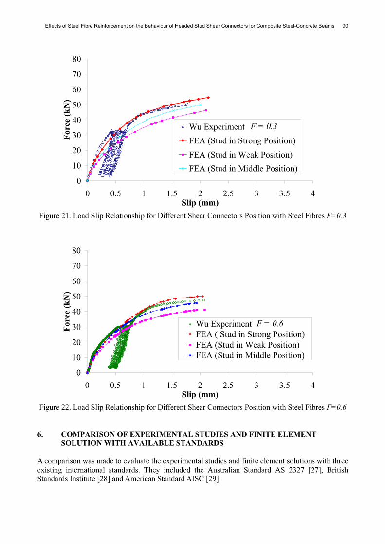
Different Fibre Contents for Profiled Slabs 5.4 Positioning of Shear Connectors in the Profiled Slab Finite element studies have been undertaken in order to look at the effect of shear connectors placed in different positions in the profiled slab. The different positions of the shear connectors are illustrated in Figure 19. In the initial finite element analysis, the shear connectors were placed in the perceived strong position. They are similar to the experimental tests undertaken by Wu [10]. When there were no steel fibres added to the concrete, the load-deflection behaviour of the push test shows that the failure load was 52 kN. In the weak position of the finite element models, the failure load decreased to 41 kN, which is equivalent to a reduction of about 22 % in the strength of the shear connectors. The finite element model demonstrates that the concrete element surrounding the shear connectors starts to fail. When load is applied to the middle position of the profiled slab, the specimen also did not reach the strength attained by the shear connectors that were placed in the strong region. The shear connectors’ strength reduced to a value of 46 kN, which is a 11 % reduction. The results are shown in Figure 20 and it can also be observed that the shear connectors in the strong position are more ductile than the other two positions. For the strong and middle positions of the shear connectors, their stiffness is similar. Conversely, the stiffness in the weak position is lower than the other two positions. When steel fibres with a quantity F=0.3 were added to the concrete, the shear connectors in the strong position attained an ultimate load of 55 kN. In the weak position of the finite element models, the load applied decreases to 46 kN, which is a reduction of 15 % in strength. The middle position of the shear connectors shows a maximum load 50 kN, which is an 8 % reduction when compared with the strong side. This is illustrated in Figure 21. When compared with concrete without steel fibres, the reduction in strength is lower. This observation suggests that the steel fibres assist to prevent concrete from cracking.

89 O.Mirza and B.Uy
When steel fibres F=0.6 were added into the concrete, the strong position had an ultimate load of 50 kN. Both weak and middle positions of the finite element models were analysed, and it was shown in Figure 22 that the load was reduced to 41 kN and 46 kN, respectively. The reductions of 18 % and 8 % in the strengths when compared with the addition of steel fibres F=0.3 showed that there is an optimum value at which the increase in strength in relation to the amount of steel fibres in concrete becomes minimum.
Figure 19. Position of Shear Connectors in Push Test Specimens
0
10
20
30
40
50
60
0 1 2 3 4 5Slip (mm)
Forc
e (k
N)
Wu ExperimentFEA (Stud in Strong Position)FEA (Stud in Weak Position)FEA (Stud in Middle Position)
F = 0
Figure 20. Load Slip Relationship for Different Shear Connectors Position Without Steel Fibres
Effects of Steel Fibre Reinforcement on the Behaviour of Headed Stud Shear Connectors for Composite Steel-Concrete Beams 90
0
10
20
30
40
50
60
70
80
0 0.5 1 1.5 2 2.5 3 3.5 4Slip (mm)
Forc
e (k
N)
Wu Experiment FEA (Stud in Strong Position)FEA (Stud in Weak Position)FEA (Stud in Middle Position)
F = 0.3
Figure 21. Load Slip Relationship for Different Shear Connectors Position with Steel Fibres F=0.3
0
10
20
30
40
50
60
70
80
0 0.5 1 1.5 2 2.5 3 3.5 4Slip (mm)
Forc
e (k
N)
Wu ExperimentFEA ( Stud in Strong Position)FEA (Stud in Weak Position)FEA (Stud in Middle Position)
F = 0.6
Figure 22. Load Slip Relationship for Different Shear Connectors Position with Steel Fibres F=0.6 6. COMPARISON OF EXPERIMENTAL STUDIES AND FINITE ELEMENT
SOLUTION WITH AVAILABLE STANDARDS A comparison was made to evaluate the experimental studies and finite element solutions with three existing international standards. They included the Australian Standard AS 2327 [27], British Standards Institute [28] and American Standard AISC [29].

91 O.Mirza and B.Uy
The strength of the shear connector is dependent on four principal factors; Ec is the mean modulus of elasticity of the concrete, Esc is the modulus of elasticity of the shear connector, fc is the compressive strength of the concrete and fus is the ultimate strength of the shear connector. The failure of a stud when steel fracture dominates is given by:
usAS fdP 263.0= (9a)
usEC fdP 2628.0= (9b)
usAISC fdP 2785.0= (9c) In each equation above, the stud failure will only take place when the concrete strength is relatively high. When the concrete is weak, then Eq. 10a, b and c will tend to govern. The equations below depend greatly on fck which is the characteristic compressive cylinder strength of the concrete and Ec is defined as the mean modulus of the elasticity of concrete.
cckAS EfdP 231.0= (10a)
cckEC EfdP 229.0= (10b)
cckAISC Efd.P 2390= (10c) When the steel profiled slab is taken into consideration, Eq. 9 and 10 above are replaced by a reduction factor k. The value of k is defined in the equations below:
)/18.0(148.1 nk AS −= (11a)
lim,17.0t
pp
oEC k
hh
hb
nk ≤⎟
⎟⎠
⎞⎜⎜⎝
⎛−⎟
⎟⎠
⎞⎜⎜⎝
⎛⎟⎟⎠
⎞⎜⎜⎝
⎛⎟⎟⎠
⎞⎜⎜⎝
⎛= (11b)
11850≤⎟
⎟⎠
⎞⎜⎜⎝
⎛−⎟
⎟⎠
⎞⎜⎜⎝
⎛⎟⎟⎠
⎞⎜⎜⎝
⎛⎟⎟⎠
⎞⎜⎜⎝
⎛=
pp
oAISC h
hhb
n.k (11c)
where n is the number of studs, bo is the width of the steel profiled ribs, hp is the height of the decking profile, h is the height of the stud. A summary of the ultimate loads for the shear connector, P which is calculated using the Australian Standard, British Standard and American Standard is given in Table 4. Table 4 shows that both the experimental results and finite element solution fall between the theoretical values from the three standards. For the solid slab, the calculated theoretical values for both the Australian and British Standards corresponded with the experimental observations. On the other hand, the American Standards seem to be less conservative because the theoretical calculations prove that the shear connectors have higher capacities when compared with the experiments. For the profiled slab, current design rules are adjusted purely based on a reduction factor k to the empirical strengths of solid slab beams. Shear connection behaviour in reality is a complex mechanism and the logic of this approach is questionable, as the theoretical calculations contradict the experimental observations shown in Table 3.

Effects of Steel Fibre Reinforcement on the Behaviour of Headed Stud Shear Connectors for Composite Steel-Concrete Beams 92
Table 4. Comparison of Ultimate Load of Shear Connector for Different Standard Australian Standard British Standard American Standard Slab F Stud Con. Stud Con. Stud Con.
0 113.7 75.3 113.4 79.7 141.7 94.7 0.3 130.8 86.6 130.4 91.7 162.9 108.9
S.S
0.6 142.1 94.1 141.7 99.7 177.1 118.4 0 56.9 37.6 35.1 24.7 53.8 36.0
0.3 65.4 43.3 40.4 28.4 61.9 41.4 P.S
0.6 71.1 47.1 43.9 30.9 67.3 45.0 S.S denotes solid slab, P.S denotes profiled slab, Stud denotes stud failure, Con. denotes concrete failure.
7. CONCLUSIONS This paper discusses five key issues in the push testing of shear stud connectors. An accurate finite element model has been developed to investigate the behaviour of the shear connection in composite steel-concrete beams for both solid and profiled slabs. Based on the comparisons between the results obtained from finite element models and available experimental results, it was observed that they are in good agreement. All the failure modes were accurately predicted by the finite element model. One primary issue that has been solved when steel fibres were included in a composite steel-concrete beam was the improved stiffness and ductility for both the solid and profiled slabs. Even though steel fibres did not show any major gain in concrete strength, the effectiveness of steel fibres is only shown when the concrete begins cracking, particularly in profiled slabs. From both the experimental tests and finite element analysis, it is illustrated that the inclusion of steel fibres in concrete improves the cracking load of the concrete. This is a major advantage especially for continuous beams in hogging moment regions. Moreover, the ultimate load of the push tests also increases with the inclusion of steel fibres for both the solid and profiled slabs. There are three differences between the profiled steel sheeting and solid slab varieties. One of them is the failure mode. For the solid slab, the failure mode is shear connection failure whereas as for the profiled slab, failure is dominated by concrete failure as discussed in section 5. Stresses in the shear connector and concrete are lower compared with those in the solid slab, due to the addition of the steel profile. It also can be observed that the solid slab generally has a higher ultimate load compared with that of the slab with profiled steel sheeting. The positioning of the shear connectors in composite beams has been discussed in this paper. It was concluded that both the strong and middle positions have similar stiffness, whilst the stiffness for the weak position of shear connectors is roughly 10 % lower. The ultimate loads for the shear connectors reduced by 22 % and 11 % for both the weak and middle positions, respectively. When steel fibres of F=0.3 were added to the specimens, the ultimate load was reduced by 15 % and 8 %. When compared with concrete without steel fibres, the load reduction value is less significant. On the other hand, when steel fibres with a factor of F=0.6 were added to the specimens, the ultimate strength showed reductions of 18 % and 8 % for both the weak and middle positions, respectively. As a conclusion, steel fibres are introduced to provide desirable characteristics such as increased strength and ductility in composite steel and concrete beams, but there is an optimum value for the steel fibre dosage included in the concrete.

93 O.Mirza and B.Uy
Lastly, when the Australian, British and American Standards are compared, both experimental and finite element results seem to be in good agreement with the Australian and British Standards, however the American Standard seems to be less conservative for solid slabs. Consequently for profiled slabs this issue should be considered carefully by the designer. Composite steel-concrete beams with the inclusion of steel fibres showed an improvement in cracking load. Studies considering continuous beams in hogging moment regions with the inclusion of steel fibres to look at the cracking behaviour and ductility will be subjected to further research in this project. Moreover, the reduction factor for the profiled slab requires augmentation for all the international standards. LIST OF NOTATION bo width of steel profiled ribs d diameter of shear connectors E elastic modulus of concrete Es elastic modulus of steel fibres and shear connectors Ec mean modulus of elasticity of concrete fc mean compressive strength of concrete fck, f´c characteristic strength of compressive cylinder strength of concrete ft tensile strength of concrete ftu residual strength of concrete fus ultimate stress of shear connectors F fibre content h height of shear connectors hp height of the decking of the profiled slab k reduction factor for profiled slab L/d fibre aspect ratio n number of shear connectors in a shear span P shear capacity of shear connectors s longitudinal shear slip Vf fibre volume fraction α, β parameters in load-slip characteristics of shear connectors εc concrete compressive strain ε'c strain corresponding to f'c
εco strain value at yield stress εcu ultimate compressive strain εps strain value when strain hardening commences εus ultimate yield strain εys yield strain γ parameter used for stress-strain curve for concrete η fibre orientation in three dimensional random distribution σc concrete compressive stress τd bond stress

Effects of Steel Fibre Reinforcement on the Behaviour of Headed Stud Shear Connectors for Composite Steel-Concrete Beams 94
SUBSCRIPTS AS Australian Standard AISC American Standard c concrete slab EC British Standard (Eurocode) s structural steel beam sc shear connection y yield u ultimate ACKNOWLEDGEMENTS The authors would like to thank the Australian Research Council Linkage Grant Scheme and BlueScope Lysaght, Sydney for providing funding for this project and Messrs Becher and Wu from the University of Wollongong for their assistance in the preparation of the experimental work. Furthermore the authors would like to thank the University of Western Sydney for providing a conducive environment for the authors to prepare this paper. REFERENCES [1] Martin, D.A., "Steel-fibre-reinforced Concrete Floors on Composite Metal Decking",
Concrete (London), 2003; Vol. 37, No. 8, pp. 31-32. [2] Lam, D. and El-Lobody, E., "Behaviour of Headed Stud Shear Connectors in Composite
Beam", Journal of Structural Engineering-ASCE, 2005, Vol. 131, No. 1, pp. 96-107. [3] Kim, B., Wright, H.D. and Cairns, R., "The Behaviour of Through-deck Welded Shear
Connectors: An Experimental and Numerical Study", Journal of Constructional Steel Research, 2001, Vol. 57, No. 12, pp. 1359.
[4] El-Lobody, E. and Young, B., "Performance of Shear Connection in Composite Beams with Profiled Steel Sheeting", Journal of Constructional Steel Research, 2006, Vol. 62, No. 7, pp. 682-694.
[5] Lam, D. and Nip, T.F., "Effects of Steel Fibres Reinforcement on Shear Studs Capacity of Composite Beams", Technical Report, School of Civil Engineering, University of Leed, 2002.
[6] Craig, R.J., Mookerjee, A., Roessler, H., Jr. and Kulik, K., "Steel Reinforced Fiber Concrete Composite", Columbus, OH, USA, 1985, pp. 406-407.
[7] Robery, P., "Construction of Composite Floor Slabs Using Steel Fibre Reinforced Concrete", Structural Engineer, 2002, Vol. 80, No. 3-24, pp. 15-17.
[8] Roberts-Wollmann, C.L., Guirola, M. and Easterling, W.S., "Strength and Performance of Fiber Reinforced Concrete Composite Slabs", Journal of Structural Engineering, ASCE, 2004, Vol. 130, No. 3, pp. 520-528.
[9] Becher, L., "Behaviour and Design of Composite Beams Using Fibre Reinforced Composite Slabs", in Faculty of Engineering, 2005, University of Wollongong, Wollongong, pp. 75.
[10] Wu, J., "Behaviour and Design of Composite Beams Using Fibre Reinfroced Composite Slabs", in Faculty of Engineering, 2006, University of Wollongong, Wollongong, pp. 191.
[11] British Standards Institution, "Design of Composite Steel and Concrete Structures, Part 1.1 General Rules and Rules for Buildings, British Standard Institute, London; ENV 1994-1-1; 2004.

95 O.Mirza and B.Uy
[12] Karlsson and Sonrensen, "Analysis User's Manual Version 6.5, Hibbitt, Pawtucket, R.I., 2006.
[13] Karlsson and Sonrensen, "User's Manual Version 6.5", Hibbitt, Pawtucket, R.I., 2006. [14] Karlsson and Sonrensen, "Theory manual version 6.5", Hibbitt, Pawtucket, R.I., 2006. [15] Carreira, D. and Chu, K., "Stress-strain Relationship for Plain Concrete in Compression",
Journal of ACI Structural, 1985; Vol. 82, No. 11, pp. 797-804. [16] Liang, Q., Uy, B., Bradford, M.A. and Ronagh, H.R., "Ultimate Strength of Continuous
Composite Beams in Combined Bending and Shear", Journal of Constructional Steel Research, 2004, Vol. 60, pp. 1109-1128.
[17] Lok, T. and Xiao, J., "Flexural Strength Assessment of Steel Fiber Reinforced Concrete", Journal of Materials in Civil Engineering, 1999, Vol. 11, No. 3, pp. 188-196.
[18] Swamy, R.N. and Al-Ta'an, S.a., "Deformation and Ultimate Strength in Flexural of Reinfroced Concrete Beams Made with Steel Fiber Concrete," Journal of ACI Structural, 1981, Vol. 78, No. 36, pp. 395-405.
[19] Hassoun, M.N. and Sahebjam, K., "Plastic Hinge in Two-span Reinforced Concrete Beams Containing Steel Fibers", in Proceeding Canada Society of Civil Engineering, Canada, 1985, pp. 119-139.
[20] Lok, T.S. and Xiao, J.R., "Tensile Behaviour and Moment-curvature Relationship of Steel Fibre Reinforced Concrete", Magazine of Concrete Research, 1998, Vol. 50, No. 4, pp. 359-368.
[21] Hannant, D.J., "Fiber Cement and Fiber Concrete", New York, Wiley, 1978. [22] Loh, H.Y., Uy, B. and Bradford, M.A., "The Effects of Partial Shear Connection in the
Hogging Moment Region of Composite Beams Part II - Analytical Study", Journal of Constructional Steel Research, 2003, Vol. 60, pp. 921-962.
[23] Aribert, J. and Labib, A., "Modèle calcul èlasto-plastique de pustres mixtes a connexion partielle", Journal of Construct Metallique, 1982, Vol. 4, pp. 3-51.
[24] Johnson, R. and Molenstra, N., "Partial Shear Connection in Composite Beams for Building", in Proceeding Institute Civil Engineer, London, 1991, pp. 679-704.
[25] Gattesco, N. and Giuriani, E., "Experimental Study on Stud Shear Connectors Subjected to Cyclic Loading", Journal of Constructional Steel Research, 1996, Vol. 38, No. 1, pp. 1-21.
[26] Yam, L.C.P., "Design of Composite Steel-concrete Structures", London, Surrey University Press, 1981.
[27] AS 2327, A.S. Composite Structures, Part 1: Simply Supported Beams, Standard Australia International, 2003, AS 2327, pp. 1-2003.
[28] British Standards Institute, "Design of Composite Steel and Concrete Structures", Part 1.1 General Rules and Rules for Buildings, British Standard Institute, London; ENV 1994-1-1; 2004.
[29] AISC, Load and Resistance Factor Design Specification (LRFD), American Institute of Steel Construction, 1999.


![Coir Fibre Reinforcement and Application in Polymer ... · Coir Fibre Reinforcement and Application in Polymer Composites: A Review D. Verma1*, ... Matrices [5] materials in composites](https://img.pdfslide.us/doc/110x75/5e3d60412c5aab7cd60ded2f/coir-fibre-reinforcement-and-application-in-polymer-coir-fibre-reinforcement.jpg)