Embed Size (px)
Citation preview

Effects of Near-Fault Ground Shaking on Sliding SystemsG. Gazetas, M.ASCE1; E. Garini2; I. Anastasopoulos3; and T. Georgarakos4
Abstract: A numerical study is presented for a rigid block supported through a frictional contact surface on a horizontal or an inclinedplane, and subjected to horizontal or slope-parallel excitation. The latter is described with idealized pulses and near-fault seismic recordsstrongly influenced by forward-directivity or fling-step effects �from Northridge, Kobe, Kocaeli, Chi-Chi, Aegion�. In addition to the wellknown dependence of the resulting block slippage on variables such as the peak base velocity, the peak base acceleration, and the criticalacceleration ratio, our study has consistently and repeatedly revealed a profound sensitivity of both maximum and residual slippage: �1�on the sequence and even the details of the pulses contained in the excitation and �2� on the direction �+ or �� in which the shaking ofthe inclined plane is imposed. By contrast, the slippage is not affected to any measurable degree by even the strongest vertical componentsof the accelerograms. Moreover, the slippage from a specific record may often be poorly correlated with its Arias intensity. These findingsmay contradict some of the prevailing beliefs that emanate from statistical correlation studies. The upper-bound sliding displacementsfrom near-fault excitations may substantially exceed the values obtained from some of the currently available design charts.
DOI: 10.1061/�ASCE�GT.1943-5606.0000174
CE Database subject headings: Sliding; Seismic effects; Ground motion; Symmetry; Asymmetry.
Introduction
Ground shaking in the close neighborhood of a rupturing seismicfault may be affected by wave propagation effects known as “for-ward directivity” and by tectonic deformations producing a per-manent ground offset known as “fling step.” The former effect isthe outcome of the coherent arrival of seismic waves emittedfrom a seismogenetic fault when its rupturing propagates towardthe site. It manifests itself with a single long-period high-amplitude pulse occurring near the beginning of shaking, and ori-ented perpendicularly to the fault �Somerville 2000�. The fling-step effect is the outcome of the tectonic permanent deformationof the earth in the proximity of the fault. It manifests itself in therecord with a static residual displacement, oriented parallel to thefault strike with strike-slip earthquakes and perpendicular to thefault with purely dip-slip �normal or thrust� earthquakes �Abraha-mson 2001�.
Fig. 1�a� is a sketch, of a strike-slip event, portraying the ide-alized “signatures” of the two phenomena on the fault-normal andfault-parallel components of the displacement record. Fig. 1�b�depicts two remarkable accelerograms, TCU-068 �from Chi-Chi1999� and Fukiai �from Kobe 1995� exhibiting fling-step andforward-directivity effects, respectively. The velocity time history
1Professor, Laboratory of Soil Mechanics, National Technical Univ.,Athens 15342, Greece �corresponding author�.
2Ph.D. Student, Laboratory of Soil Mechanics, National TechnicalUniv., Athens 15342, Greece.
3Adjunct Lecturer, Laboratory of Soil Mechanics, National TechnicalUniv., Athens 15342, Greece.
4Ph.D. Student, Laboratory of Soil Mechanics, National TechnicalUniv., Athens 15342, Greece.
Note. This manuscript was submitted on September 22, 2008; ap-proved on June 10, 2009; published online on November 13, 2009. Dis-cussion period open until May 1, 2010; separate discussions must besubmitted for individual papers. This paper is part of the Journal ofGeotechnical and Geoenvironmental Engineering, Vol. 135, No. 12,December 1, 2009. ©ASCE, ISSN 1090-0241/2009/12-1906–1921/
$25.00.1906 / JOURNAL OF GEOTECHNICAL AND GEOENVIRONMENTAL ENGIN
Downloaded 05 Dec 2009 to 147.102.161.124. Redistribution subject to
of TCU-068 contains a large pulse �2.6 m/s� of huge duration�6.3 s�, which is consistent with the permanent ground offset ofabout 8 m that can be seen in the derived displacement record,and which has actually been observed in the field. The derivedvelocity time history of Fukiai contains several cycles with adevastating maximum velocity step �V�2.3 m /s. The destruc-tive capacity of this quantity was first elaborated by Bertero et al.�1976�.
A significant amount of research has been devoted to the twophenomena, especially in the aftermath of the Northridge, Kobe,Kocaeli, and Chi-Chi earthquakes. That research has so far fo-cused: first, on identifying, interpreting, and mathematically rep-resenting the effects of “directivity” and “fling” on the groundmotions �Singh 1985; Somerville 2000,2003; Abrahamson 2001;Makris and Roussos 2000; Mavroeidis and Papageorgiou 2003;Hisada and Bielak 2003; Bray and Rodriguez-Marek 2004;Haward et al. 2005�; then, on developing empirical predictiverelationships for the parameter characterization of the directivityor fling related pulses �Somerville et al. 1997; Bray andRodriguez-Marek 2004; Xie et al. 2005�; and finally, on assessingthe potential of directivity and fling pulses to inflict damagein a variety of geotechnical and structural systems �for example,Bertero et al. 1978; Singh 1985; Hall et al. 1995; Gazetas 1996;Kramer and Smith 1997; Iwan et al. 2000; Sasani and Bertero2000; Makris and Roussos 2000; Alavi and Krawinkler 2000;Jangid and Kelly 2001; Pavlou and Constantinou 2004; Shenet al. 2004; Mavroeidis et al. 2004; Xu et al. 2006; Changhai et al.2007�.
The work presented here belongs in the latter category. Itsummarizes studies on the effects of near-fault motions on twoidealized sliding systems: �1� a rigid block in contact with �restingon� a horizontal base; �2� a rigid block resting on an inclinedplane, of angle � �Fig. 2�. In both cases the contact betweenstructure and base is rigid-ideally plastic, obeying Coulomb’s fric-tion law with a constant coefficient of friction, �. The horizontalor inclined base is subjected to parallel excitation, i.e., horizontalmotion in Case 1 and motion inclined at an angle � in Case 2.
Furthermore, the effect of a simultaneous vertical accelerationEERING © ASCE / DECEMBER 2009
ASCE license or copyright; see http://pubs.asce.org/copyright

time history is also explored for Case 1, while a horizontal and avertical acceleration are also imposed in Case 2. As excitation weutilize idealized wavelets and near-fault seismic records stronglyinfluenced by forward-directivity or fling-step effects �Northridge1994; Kobe 1995; Kocaeli 1999; Chi-Chi 1999; Aegion 1995�.Some additional records are also used for comparison.
The destructive potential of long duration acceleration pulses,which is one of the outcomes of directivity and fling effects, hasbeen demonstrated in the pioneering work of Bertero et al. �1976�in connection with the heavy damage of the Olive View Hospitalduring the San Fernando 1971 earthquake. One of the significantconclusions of his research was that:
“The types of excitation that induce the maximum re-sponse in elastic and non-elastic systems are fundamen-tally different and hence one can not derive the maximumnon-elastic response from the corresponding elastic one”�Bertero et al. 1976�.
The preceding remark has motivated our choice of the ideallyrigid-plastic constant-friction systems: in addition to their obviousdirect use in earthquake engineering, they are representative of
Faultstrike
Directivity pulse
Parallel componentof Displacement
Fling step
Dresidual = 0
Dresidual
Site
Normal componentof Displacement
t
t
(a)
6.3 s
Α(t)
V(t)
0.4
0
0.4
0
-3
0
3
0
2.6 m/s
-
0
5
10
0 25
9.2 mD(t)
Fling StepExample:
(TCU 068)
t : s-0.4
0.5
2 16
-1.5
1
2
-10
0
10
2
Α(t)
D(t)
V(t)
0.4 m
1.4 s
Forward DirectivityExample:
(Fukiai)
t : s
∆V ≈ 2.3 m/s
(b)
Fig. 1. �a� Schematic explanation of the forward-directivity andfling-step phenomena as reflected in the displacement records; �b�examples of actual accelerograms bearing the “signature” of the twoeffects: TCU-068 record �Chi-Chi 1999� and Fukiai record �Kobe1995�
extremely inelastic behavior. The anticipation was that such sys-
JOURNAL OF GEOTECHNICAL AND GEOE
Downloaded 05 Dec 2009 to 147.102.161.124. Redistribution subject to
tems would be far more sensitive than the purely linear elasticsystems �the other extreme of reality� to the peculiarity of near-fault ground shaking. The results presented in the paper confirmthis expectation.
Further objectives of our research are:• To quantify the maximum and permanent slippage as a func-
tion: �1� of the amplitude and duration of the near-fault pulses;�2� of the nature of the main pulse and the number and se-quence of pulses.
• To discuss the differences between symmetric and asymmetricsliding �Cases 1 and 2�, and to explore the importance of thedirection �+ or �� of a particular near-fault excitation in theasymmetric Case 2.
• To investigate the role of large vertical accelerations simulta-neously acting with horizontal accelerations, as is appropriatefor near-fault motions.It is hoped that a deeper insight will be gained from our study
into the nature and consequence of directivity- and fling-affectedmotion. However, the development of design charts/equations tocomplement the presently available statistical relations is only asecondary goal of this paper.
Seismic Sliding of Rigid Blockon Horizontal Plane
This problem is of direct application to seismic base isolation ofrigid structures using low-friction bearings, and to isolation ofembankments from the underlying ground using geosynthetic lin-ers. Moreover, in an indirect qualitative sense, it can be consid-ered as an analog for a host of geotechnical and earthquakeproblems, such as the response of a stiff soil crust on an under-lying soft thin layer, the sliding of a stiff light structure with
AP(t)
D(t)
m
β
(c)
AH (t)
D(t)
m
(a)
μ
AH(t)
m
(b)
μ
AV(t)
AV(t)AΗ(t)
D(t)
m (e)
AΗ(t)
D(t)
(d)m
μ
μ
μ
D(t)
Fig. 2. Five rigid block problems studied in the paper: ��a� and �b��sliding on horizontal plane undergoing only-horizontal andhorizontal-and-vertical motion, respectively; �c� sliding on inclinedplane excited by motion parallel to the slope; ��d� and �e�� sliding oninclined plane undergoing only-horizontal and horizontal-and-verticalmotion, respectively
surface foundation on dense ground, the in-ground isolation of
NVIRONMENTAL ENGINEERING © ASCE / DECEMBER 2009 / 1907
ASCE license or copyright; see http://pubs.asce.org/copyright

structures using geomembranes. Perhaps equally important is theresemblance of the restoring force-displacement mechanism ofthis system to that of a very stiff elastoplastic system.
The mechanics of the system are well understood and need nofurther explanation here. The rigid block, simply resting on a basewith an interface obeying Coulomb’s friction law with a singlecoefficient of friction �, will experience accelerations that cannotexceed, by Newton’s law, a critical value
AC � �Cg = �g �1�
�s long as the peak ground acceleration AH��Hg does not ex-ceed AC in absolute value, the block does not slide but moveswith the ground. When AH��Hg surpasses AC=�g the blockacceleration remains constant �and equal to �g�, and sliding takesplace until the velocities of the block and the ground equalize. Atthat moment, if ground acceleration is smaller than the criticalacceleration, AC=�g, sliding stops.
0.30 g
Ricker, fo = 2 Hz
T-Ricker, fo = 2 Hz
0
0.5
1
0 0.2 0.4 0.6 0.8 1
T : s
SA : g
0.3
RickerT-Ricker
0.30 g
Fig. 3. Two idealized time histories �“wavelets”� used as base exci-tation, with their response acceleration spectra SA :g−T �peak groundacceleration: 0.30g�
0.42 g
TCU 068( Chi-Chi 1999)
0.54 g
AEGION( Aegion 1995)
Fig. 4. Accelerograms of actual near-fault recordings used in th
1908 / JOURNAL OF GEOTECHNICAL AND GEOENVIRONMENTAL ENGIN
Downloaded 05 Dec 2009 to 147.102.161.124. Redistribution subject to
The penalty for limiting the block acceleration to the level ofthe coefficient of friction is a sliding displacement �“slippage”�,which is found to be dependent on four basic variables:• The maximum peak ground acceleration AH��Hg.• The dominant frequency f0 of ground excitation.• The ratio � /�H.• The form and the details of the ground excitation.A large number of analyses were performed to understand theinfluence of these variables. Only the highlights are presented inthe sequel.
Excitation
Two idealized wavelets are used as simple representation of near-fault pulses �Fig. 3�:• A three-pulse Ricker “wavelet,” described by its amplitude
AH=�Hg and characteristic frequency f0.• A one-pulse truncated Ricker wavelet �“T-Ricker”� which is
derived from the original wavelet by ignoring the first and lasthalf-cycles.Moreover, we also use three well-known actual accelerograms
from the near-fault worldwide bank of records: Rinaldi�Northridge 1994�, Fukiai �Kobe 1995�, TCU-068 �Chi-Chi1999�, and Aegion �Aegion 1995�. Fig. 4 shows these records.
Dimensional Analysis and Characteristic Results
It is easily shown that the maximum sliding displacement, D, canbe expressed in one of the following alternative nondimensionalexpressions
Dfo2
AH
or
DAH
VH2 = Func� �
aH; shape and sequence of pulse�s�� �2�
Note that the dimensionless variables on the left-hand side ofEq. �2� had already been suggested in the seminal work ofNewmark 1965. The preceding dimensionless expression is quitesimilar with the one presented by Yegian et al. �1991a� �see alsoKramer �1996��.
The great importance of the dominant �“characteristic”� fre-quency of excitation, f0, is obvious: for given acceleration ampli-
0.85 g FUKIAI( Kobe 1995)
0.93 g
RINALDI( Northridge 1994)
er �all time histories are in the same time and amplitude scale�
e papEERING © ASCE / DECEMBER 2009
ASCE license or copyright; see http://pubs.asce.org/copyright

tude AH and nature of pulses, D is inversely proportional to f02.
Fig. 5 portrays this dependence for a T-Ricker type excitationwith AH=0.60g.
Influence of � /�H Ratio: Safe Gulf Paradox
In view of Eq. �2�, the expectation of course would be that Func isa monotonically decreasing function of � /�H—the latter ratioplaying the role of an instantaneous factor of safety against slid-ing. In other words, one might have expected a monotonic de-crease of slippage with increasing friction coefficient � for agiven excitation. The results prove that this is not always the case.Fig. 6 displays �parametrically with respect to f0� the dimension-less maximum slippage in terms of the � /�H ratio for a Rickerexcitation. It reveals that, while initially the slippage increaseswith the reduction of � /�H, it reaches a peak value for � /�H
�0.4, beyond which it decreases until the value � /�H�0.2,where a local minimum is observed before its final ascent withfurther decreasing � /�H. Apparently, an unexpected safe gulf ex-ists, which would be beneficial in design—a value of � smallerthan about 0.40�H can be chosen �e.g., �=0.20�H� with which
0 1 2 3 40
5
10
15
20
25
30
0.10.20.40.60.8
μ / αΗD
:cm
fO
Fig. 5. Effect of characteristic frequency, fo, and of � /�H ratio onmaximum slippage �excitation: single pulse of T-Ricker wavelet�
�
1.6
3.2
0.2 0.4 0.6 0.
μ / αΗ
00
0.8
2.4
D/(VH2/AH)
�
�
Fig. 6. Effect of � /�H ratio on the dimensionless maximum sliding, freduction of D, with decreasing � /�H, for � /�H�0.4, which leads
JOURNAL OF GEOTECHNICAL AND GEOE
Downloaded 05 Dec 2009 to 147.102.161.124. Redistribution subject to
both structural acceleration and slippage are reduced below their�=0.40�H values. This phenomenon is caused by the presence ofthe first �preceding� smaller cycle in the Ricker wavelet which, asthe friction coefficient decreases, causes increasingly more sub-stantial slippage in the opposite direction �Fig. 7�. For the �trun-cated� T-Ricker excitation, where these two cycles are absent, nosuch a safe gulf is observed, and slippage increases monotonicallywith decreasing � �Fig. 8�. Evidently, the wavelet form and de-tails are of crucial importance—at least as much as the dominantfrequency and the intensity of the motion.
Excitation with Near-Fault Accelerograms:Further Surprising Results
To verify and further reinforce the validity of the aforementionedconclusions, analyses with real records have been performed. Afew characteristic results are highlighted here.
First, to develop a deeper insight into the similarity betweenthe Ricker wavelet and actual directivity-affected motions,Fig. 9�a� compares the Rinaldi record �Northridge, 1994� to afitted Ricker wavelet �AH�0.90g , f0�1 Hz�. Despite the com-plexity of real motions, the resulting sliding behavior of a blockexcited by the two motions is qualitatively similar, as seen inFig. 9�b�. But, surprisingly at first glance, the Ricker motion istwice as detrimental as the actual motion, despite the significantlylarger duration of the latter. The culprit of this unexpected behav-ior is something deceptively small: the larger �not smaller� accel-eration amplitudes of Rinaldi between � and b �i.e., betweenabout 0.16–2.10 s�! This stronger excitation, coming 0.20 s beforethe main damaging pulse �of AH�0.90g�, “displaces” the blocksignificantly in the opposite direction and thus reduces its finalslippage—another evidence of the important role of the �quiteunpredictable� detailed sequence of pulses. Note that the AriasIntensity of the Ricker “wavelet” is only 3.2 compared to 7.1 ofthe record.
A second example is given in Fig. 10. The directivity-affectedAegion accelerogram �recorded in the M =6.4 earthquake of1995� is characterized by a peak acceleration AH=0.54g at adominant period of about 0.60 s �Gazetas 1996�. A block sup-ported through a coefficient of friction �=0.054 �i.e., �C /�H
.5 Hz
Hz
Hz
Hz
0.40.15 0.6 0.8
μ / αΗ
00
Dcrit
“SafeGulf ”
erent Ricker characteristic frequencies, fo. Observe the “paradoxical”dditional safe gulf for lower values of the � /�H ratio.
8
fo = 0
fo = 1
fo = 2
fo = 4
or diffto an a
NVIRONMENTAL ENGINEERING © ASCE / DECEMBER 2009 / 1909
ASCE license or copyright; see http://pubs.asce.org/copyright

-3
-2
-1
0
1
2
2 2.5 3
-3
-2
-1
0
1
2
2 2.5 3
-3
-2
-1
0
1
2
2 2.5 3
μ / αΗ = 0.2
Time : s
μ / αΗ = 0.1
2.5 320
1
2
3
-3
-2
-1
Dres
D
Dres
D
2.5 320
μ / αΗ = 0.4
Dres
320
D
D/(VH2/AH) 1
2
3
-3
-2
-1
1
2
3
-3
-2
-1
� � �
A(t):m/s2
GroundSliding block
Fig. 7. Explanation of the safe gulf paradox of Fig. 6: acceleration and sliding-displacement time histories for a single wavelet frequency fo
=4 Hz and different values of � /�H ratio �0.1, 0.2, and 0.4�
0 0.2 0.4 0.6 0.80
2
4
6
8
10
μ / αΗ
fo = 4 Hz
Df o2/A
H
fo = 2 Hzfo = 1 Hz
fo = 4 Hzfo = 2 Hzfo = 1 Hz
T-Ricker
Ricker
T-Ricker
Ricker
}}
Fig. 8. Dimensionless maximum sliding for Ricker and T-Rickerexcitation, for different values of the wavelet frequency butsame amplitude AH. Notice the dramatic effect of the type of ex-citation.
1910 / JOURNAL OF GEOTECHNICAL AND GEOENVIRONMENTAL ENGIN
Downloaded 05 Dec 2009 to 147.102.161.124. Redistribution subject to
D/(V
H2 /A H)
Ricker
Rinaldi5
0
-5
-10
A(t):m/s2
t : s0 102 4 6 8
10
00
3.2
0.1 0.2
μ / αΗ
1.6
0.8
2.4
0.3 0.4 0.5 0.6 0.8 0.90.7
Ricker
Rinaldi
a b
Fig. 9. Approximation of the Rinaldi-228° record with a simpleRicker wavelet �top plot�. Comparison of sliding induced by thesetwo motions �bottom plot�. Despite the similarity in the form of theresulting curves the �smaller duration� Ricker excitation leads to twotimes higher displacements.
EERING © ASCE / DECEMBER 2009
ASCE license or copyright; see http://pubs.asce.org/copyright

=0.1� experiences the acceleration, velocity, and sliding-displacement histories shown in Fig. 10�a�. When the large accel-eration pulse is cut off at its middle, the slippage of the blockparadoxically increases. The provided velocity time histories ofthe ground and the block in Fig. 10�b� help resolve the paradox.For this particular excitation and this specific ratio of �C /�H,the role of the 0.54g pulse is beneficial: it “puts the breaks”and reverses the sliding—hence the maximum slippage is D=0.08 m and the residual merely Dres=0.02 m. The trimming ofthis pulse to half of its original peak value undermines somewhatthe “breaking” action and eliminates most of the “reversing”action—hence D=0.11 m and Dres=0.10 m!
A third example: comparison of the sliding potential of thetwo components of the Chi-Chi TCU-068 record. Significant flingeffects are present in these components which are portrayed inFig. 11�a�, with their response spectra compared in Fig. 11�b�.
Notice that the east-west �EW� component has greater peakacceleration compared to the north-south �NS� component �0.50gto 0.36g�; in addition, its spectral acceleration values are alsohigher over broad period ranges. Hence, one might have antici-pated the largest slippage to occur with the EW component.Reality �Fig. 11�c�� shows quite the opposite by a large margin�2.5 to 1 for the peak slippage, and 5 to 1 for the residual�! Thisis clearly due exclusively to the long-duration one-sided pulsethat is contained in the NS record.
The reader should not fail to notice that in all the aforemen-
-0.6
-0.3
0
0.3
2
-0.04
0
0.04
0.08
0.12
2 4 6 8
-6
-3
0
3
6
2
0.54 g
0.08 m
0.02 m
Α(t) :
m/s2
V(t) :
m/s
D(t) :
m
Time : s
(a)
Fig. 10. Paradoxical effect of “trimming” the peak ground acceleratislippage time histories for a block on a horizontal plane with �C /�H=and reversing the sliding, is undermining by its removal.
tioned three examples the largest slippage was each and every
JOURNAL OF GEOTECHNICAL AND GEOE
Downloaded 05 Dec 2009 to 147.102.161.124. Redistribution subject to
time associated with one or more of the following:• With the smaller peak ground acceleration.• With the smaller Arias intensity.• With the smaller strong motion duration.• Not even with the larger response spectrum �except in few
cases�.One should therefore be cautious when using empirical statis-
tical correlations �which anticipate the opposite trend� to predictthe response in individual cases. This of course does not neces-sarily negate the role of statistical correlations in probabilisticseismic risk analyses.
Simultaneous Horizontal and Vertical Accelerations:Dispelling a Persevering Myth
Earthquake engineers have always been concerned about the ef-fects of the vertical component of ground acceleration. In recentyears the issue of the possible effects of vertical acceleration ondifferent structural sliding systems such as seismically isolatedbridges and buildings has been debated. Large vertical accelera-tions recorded in numerous earthquakes have fueled the discus-sion in the subject. Geotechnical engineers appear to haveaccepted the important role of vertical acceleration for retainingstructures and slopes. The vectorial synthesis of �H and �V ap-pears as a natural fact in many papers and textbooks on the sub-
.6
.3
0
.3
2
04
0
04
08
12
2 4 6 8 10
-6
-3
0
3
6
2
0.11 m0.10 m
0.27 g
Time : s
GroundSliding block
(b)
he Aegion record is illustrated in terms of acceleration, velocity, ande beneficial role in this particular case of the 0.54g peak, in breaking
-0
-0
0
10-0.
0.
0.
0.
on of t0.1. Th
ject. But is �V really significant for sliding systems?
NVIRONMENTAL ENGINEERING © ASCE / DECEMBER 2009 / 1911
ASCE license or copyright; see http://pubs.asce.org/copyright

To explore the subject, a comprehensive parameter study hasbeen conducted using both idealized and actual horizontal andvertical acceleration time histories. Only a summary of the resultsis highlighted next.
In actual records, the vertical component of the ground accel-eration is of a much higher frequency content than its horizontalcomponents—a fact arising from the nature of the P and S waveswhich dominate the vertical and horizontal ground motion, re-spectively. Exceptions to this rule are not rare. Hence, to be moregeneral in our investigation with idealized motions, a broad rangeof dominant periods of vertical motion �up to TV�0.50 s� hasbeen studied.
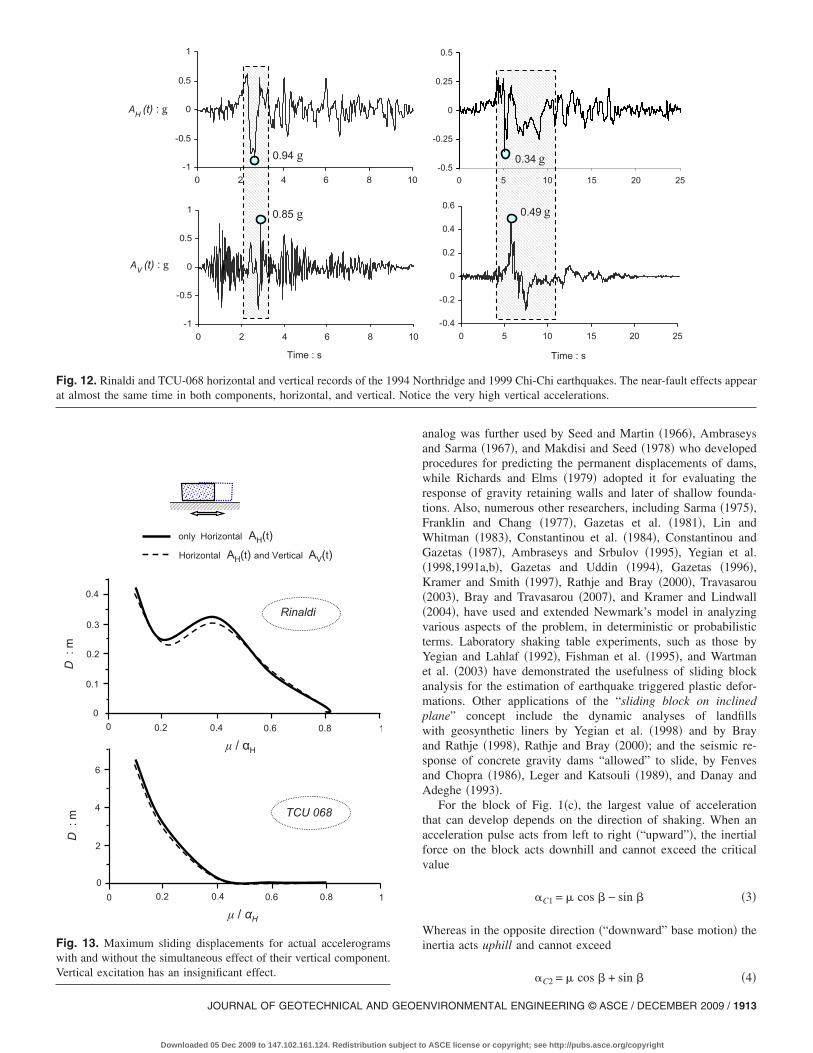
We begin with results using actual motions: pairs of horizontaland vertical components of accelerograms recorded within a fewkilometers from the fault �where the vertical component is usuallyat its strongest�. Only two characteristic results are shown here,for:• Rinaldi �Northridge�: AH�0.94g, AV�0.85g �forward direc-
tivity affected�.• TCU-068 �Chi-Chi�: AH�0.42g, AV�0.50g �fling step
affected�.�he two components of the two records are plotted for com-
parison in Fig. 12. The resulting curves of the maximum slippage,D, versus � /�H are portrayed in Fig. 13. Two curves are com-pared in each plot: one for excitation by the horizontal componentalone, and the other for the simultaneous excitation by the hori-zontal and vertical components �Fig. 13�. Apparently, even theoccurrence of very strong vertical accelerations is of no signifi-cance for the slippage of rigid blocks! A second conclusion from
10.5
SA:g
0.5
1
1.5
0
μ / αΗ
0
8
642D
:m
0.50.1 0.2 0.3 0.4 0.6 0.70
0
AH(t):m/s2
TCU 068 (NS component)
t : s
0
3
6
-3
-65 10 150
--
Fig. 11. Example of the importance of “details” of excitation on slida larger peak acceleration and larger spectral accelerations for a wide�black color� are higher by a factor of almost 3.
Fig. 13 is that for this symmetric sliding problem, the fling-
1912 / JOURNAL OF GEOTECHNICAL AND GEOENVIRONMENTAL ENGIN
Downloaded 05 Dec 2009 to 147.102.161.124. Redistribution subject to
affected Chi-Chi record, with its huge velocity pulse �as will beshown in Fig. 15 in the sequel�, is far more detrimental than thedirectivity-affected Northridge record.
It is interesting to focus on the Chi-Chi record, the verticalacceleration of which seems to be particularly severe, containinga strong and exceptionally long-period pulse �0.3g, 2.5 s� whichleads to uncommonly high �for vertical motion� spectral accelera-tion values �Fig. 12�. Yet the analysis proves that the effect ofsuch a vertical excitation would cause a mere 4% increase of themaximum and residual values of slippage �see Fig. 14�.
Numerous additional results with the Ricker wavelets as hori-zontal and vertical excitation have completely verified the afore-mentioned conclusions. Space limitations do not allow thepresentation of these results. But the reader should not be sur-prised that even when the two components are identical and theirpeak values coincide in time �a very severe and rather unlikelyincident�, the vertical excitation still has a minor effect �see Fardiset al. �2003�, Garini and Gazetas �2007��. In fact it could not bedetermined a priori whether this effect would be positive or nega-tive. Therefore, neglecting it altogether will have no measurableconsequence.
Seismic Sliding of Rigid Block on Inclined Plane
In earthquake geotechnical engineering the analog of dynamicsliding of a block on an inclined plane has been in use for esti-mating the response of earth dams, embankments, and retaining
2
NS component
EW component
0
6
4
2
μ / αΗ0.50.1 0.2 0.3 0.4 0.6 0.7 0.80
Dres:m
2.5 3T : s
NS component
EW component
t : s
TCU 068 (EW component)6
0
3
-3
-65 10 15 200
+
-
lthough the EW component of the TCU-068 record �gray color� hasof periods, the sliding displacements produced by the NS component
0.8
1.5
20
ing. Arange
walls during earthquakes. Introduced in 1965 by Newmark, the
EERING © ASCE / DECEMBER 2009
ASCE license or copyright; see http://pubs.asce.org/copyright
JOURNAL OF GEOTECHNICAL AND GEOE
Downloaded 05 Dec 2009 to 147.102.161.124. Redistribution subject to
analog was further used by Seed and Martin �1966�, Ambraseysand Sarma �1967�, and Makdisi and Seed �1978� who developedprocedures for predicting the permanent displacements of dams,while Richards and Elms �1979� adopted it for evaluating theresponse of gravity retaining walls and later of shallow founda-tions. Also, numerous other researchers, including Sarma �1975�,Franklin and Chang �1977�, Gazetas et al. �1981�, Lin andWhitman �1983�, Constantinou et al. �1984�, Constantinou andGazetas �1987�, Ambraseys and Srbulov �1995�, Yegian et al.�1998,1991a,b�, Gazetas and Uddin �1994�, Gazetas �1996�,Kramer and Smith �1997�, Rathje and Bray �2000�, Travasarou�2003�, Bray and Travasarou �2007�, and Kramer and Lindwall�2004�, have used and extended Newmark’s model in analyzingvarious aspects of the problem, in deterministic or probabilisticterms. Laboratory shaking table experiments, such as those byYegian and Lahlaf �1992�, Fishman et al. �1995�, and Wartmanet al. �2003� have demonstrated the usefulness of sliding blockanalysis for the estimation of earthquake triggered plastic defor-mations. Other applications of the “sliding block on inclinedplane” concept include the dynamic analyses of landfillswith geosynthetic liners by Yegian et al. �1998� and by Brayand Rathje �1998�, Rathje and Bray �2000�; and the seismic re-sponse of concrete gravity dams “allowed” to slide, by Fenvesand Chopra �1986�, Leger and Katsouli �1989�, and Danay andAdeghe �1993�.
For the block of Fig. 1�c�, the largest value of accelerationthat can develop depends on the direction of shaking. When anacceleration pulse acts from left to right �“upward”�, the inertialforce on the block acts downhill and cannot exceed the criticalvalue
�C1 = � cos � − sin � �3�
Whereas in the opposite direction �“downward” base motion� theinertia acts uphill and cannot exceed
-0.4
-0.2
0
0.2
0.4
0.6
0 5 10 15 20 25
Time : s
0.49 g
0.34 g-0.5
-0.25
0
0.25
0.5
0 5 10 15 20 25
rthridge and 1999 Chi-Chi earthquakes. The near-fault effects appeare the very high vertical accelerations.
-1
-0.5
0
0.5
1
0 2 4 6 8 10
Time : s
AH (t) : g
0.94 g
0.85 g
AV (t) : g
-1
-0.5
0
0.5
1
0 2 4 6 8 10
Fig. 12. Rinaldi and TCU-068 horizontal and vertical records of the 1994 Noat almost the same time in both components, horizontal, and vertical. Notic
D:m
μ / αΗ
0.4
0.3
0.2
0.1
0 0.20
0.4 0.6 0.8 1
4
2
6
0 0.20
0.4 0.6 0.8 1
μ / αΗ
TCU 068
D:m
Rinaldi
only Horizontal AH(t)Horizontal AH(t) and Vertical AV(t)
Fig. 13. Maximum sliding displacements for actual accelerogramswith and without the simultaneous effect of their vertical component.Vertical excitation has an insignificant effect.
�C2 = � cos � + sin � �4�NVIRONMENTAL ENGINEERING © ASCE / DECEMBER 2009 / 1913
ASCE license or copyright; see http://pubs.asce.org/copyright

evidently, �C1��C2. Since the geotechnical interest is usually inrelatively large values of � �e.g., �20°� and small values of thecoefficient of friction ���0.70�, the ratio �C2 /�C11. Thus,there is practically only one limiting acceleration
�C � �C1 �5�
and �C2 can be considered as infinitely large. This of courseshould not be unduly generalized: mild slopes and lined landfills,for example, will sustain both downward and upward asymmetricsliding. The results of such an asymmetric sliding are reportedherein in Fig. 20, for an inclination �=5° of the base.
As long as the upward base acceleration �H�t� does not exceed�C the block remains attached to its base, with the acceleration�H�t� of the base. Sliding downhill occurs whenever �H�t��C.Throughout sliding the acceleration remains constant equal to �C.�he movement continues until the velocities of the block and theground equalize. Knowing the critical acceleration and the timehistory of base excitation, permanent displacements in every slid-ing period are calculated by a straightforward integration process.Thanks to the transient nature of the earthquake loading, even ifthe block is subjected to a number of acceleration pulses higherthan its critical acceleration, it may only experience a small per-
-0.3
0
0.3
0.6
0 5
0.5 1
SA:g
TCU
5 10 15 20 25 300
t : sAblock(t):m/s2
0
1.510.5
-1.5
-0.5
-1
only Horizontal excitation
1
4
05
t : s
D(t)
:m
2
3
10 150
AV(t):g
0.3
0.6
0
0.3
-0.3
0.6
0
50
0
Fig. 14. Vertical component of the Chi-Chi, 1999, TCU-068 nearhorizontal acceleration and sliding displacement of the block
manent deformation rather than complete failure.
1914 / JOURNAL OF GEOTECHNICAL AND GEOENVIRONMENTAL ENGIN
Downloaded 05 Dec 2009 to 147.102.161.124. Redistribution subject to
Idealized Excitation: Dimensional Analysis
The nondimensional expressions �Eq. �2�� outlined in the previouschapter are also valid in this case with a small modification
DAH
VH2 = Func� aC
aH; �; shape of pulse, sequence of pulse;
parallel or horizontal excitation; + or − direction��6�
The validity of this expression is demonstrated in Fig. 15, withtwo excitations: a Ricker wavelet and one-cycle sine, for a broadrange of frequencies. Results are presented here only for �=25°which essentially ensures exclusively downward slippage.
Near-Fault Accelerograms: Some Results
A characteristic example showing the evolution of acceleration,velocity, and sliding displacement of a block the base of which isexcited with the fling-affected TCU-068-NS record is illustratedin Fig. 16. The very small value of the chosen critical accelerationratio, �C /�H=0.05, leads understandably to a large �maximum
15 20
2 2.5 3
Vertical
5 10 15 20 25 300
t : s
0
.51.5
1.5
0.5
-1
Horizontal and Vertical excitation
only Horizontal AH (t)
Horizontal AH (t) andVertical AV (t)
25 30 35
t : s
T : s
15 20
record �time history and 5% response spectrum� and its effect on
10
1.5
068 -
1
0
-
-
20
10
-fault
=residual� slippage. But notice that this is primarily the outcome
EERING © ASCE / DECEMBER 2009
ASCE license or copyright; see http://pubs.asce.org/copyright

of the sequence of the few long-duration pulses between about 3.3and 8.9 s. It is precisely those pulses that constitute the substantialfling of this record.
In this asymmetric-sliding case, the direction �+ or �� of thebase excitation can be of great significance. This is because thedirection determines if the most “deleterious” pulses of the recordtend to move the block uphill or downhill. Thus, Fig. 17 portraysfor two excitation directions �+ and �� the response of a slidingblock with �C /�H=0.1 subjected to the directivity-affectedRinaldi record.
�t is evident that completely different velocity and sliding his-tories are experienced by the same block to the same excitationdepending on the orientation of the inclined plane. The explana-
∆:m
ac1 / aΗ
0
0.9
1.8
2.7
3.6
4.5
0 0.1 0.2 0.3 0.4 0.5 0.6 0.
fo = 1 Hz
fo = 2 Hz
ac1 / aΗ
0
0.8
1.6
2.4
3.2
0 0.1 0.2 0.3 0.4 0.5 0.
fo = 0.67 Hz
fo = 1.5 Hz
fo = 3 Hz
αc / αp
αc / αp
D:m
D:m
1 g
1 g
1 g
Fig. 15. Normalization effect of sliding spectra in case of a T-Rickeslippage curves �left figures� vary with frequency fo whereas the nor
tion is straightforward: the highest-amplitude pulse, AH�0.90g at
JOURNAL OF GEOTECHNICAL AND GEOE
Downloaded 05 Dec 2009 to 147.102.161.124. Redistribution subject to
t�3.6 s, in one case provides the driving downward inertia“force” �right-hand side plot�, while in the opposite case it pro-vides the “braking” upward inertia �left-hand side plot�.
Fig. 18 completes the preceding comparison for three differentcritical acceleration ratios: �C /�H=0.05, 0.10, and 0.2. Appar-ently, for this particular excitation the direction-related differenceincreases. Although not shown here, when the TCU-068 recordof Fig. 12 were inverted, a slippage of 25 m rather than 8 moccurred! The importance of these findings can hardly be over-stated: two identical neighboring slopes, one opposite to the other�i.e., as in a canal�, or the two slopes of a tall embankment, mayexperience vastly different sliding deformations during near-fault
ac1 / aΗ
∆a H/V
H2
0
2
4
6
8
10
0 0.1 0.2 0.3 0.4 0.5 0.6 0.7
fo = 1 Hz
fo = 2 Hz
ac1 / aΗ
∆a H/V
H
0
0.3
0.6
0.9
1.2
1.5
0 0.1 0.2 0.3 0.4 0.5 0.6
fo = 0.67 Hz
fo = 1.5 Hz
fo = 3 Hz
αc / αp
αc / αp
ΑΑ
DD
25o Ap
25o Ap
let and a sinusoidal wavelet of one cycle. Observe that dimensionald slippage curves �right plots� converge to a single line.
7
2
6
r wavemalize
shaking!
NVIRONMENTAL ENGINEERING © ASCE / DECEMBER 2009 / 1915
ASCE license or copyright; see http://pubs.asce.org/copyright

Nonparallel and Vertical Excitation
The significance of the more realistic assumption of applying thebase motion horizontally rather than parallel to the slope, and atthe same time imposing the vertical acceleration time history, arehighlighted in Figs. 19 and 20. In this case the downward-slidingacceleration, �C, is time dependent, since it is affected by thenormal to the slope component of motion.
From Fig. 19 we conclude that for the TCU-068 record thehorizontal excitation leads to increased �by about 20%� slippage,but the simultaneous application of the vertical component of thisrecord has a negligible effect �which actually is beneficial in thisparticular case�. In Fig. 20 the preceding results are recast in theform of
0.34 g-4
-2
0
2
4
0 3 6 9
0
3
6
9
12
0 3 6 9
-2
0
2
4
0 3 6 9
2.97 m/s
25o
D(t):m
V(t):m/s
A(t):m/s2
Fig. 16. Asymmetric response time histories for the TCU-068 NSinduced by a large sequence of remarkably long duration accelerationand 3 m/s amplitude.
D = F��c/�H; � = 5 ° and 25 ° ; TCU-068� �7�
1916 / JOURNAL OF GEOTECHNICAL AND GEOENVIRONMENTAL ENGIN
Downloaded 05 Dec 2009 to 147.102.161.124. Redistribution subject to
and then compared with those corresponding to the Rinaldi record�horizontal and vertical components�. Evidently, the aforesaidconclusion is fully verified: in both cases, despite the record-highvertical accelerations, far exceeding the typical values, theslippage of the block is practically unaffected by the verticalcomponent.
Epitome: Comparison
Although it was not a main goal of this paper to provide designcurves for sliding displacements, it is worth comparing the re-sults of our study against the classical relevant charts for slidingpublished by Makdisi and Seed �1978� and Ambraseys and Sarma�1967�. The comparison is portrayed in Fig. 21. Evidently,
12 15 18 21
8.81 m
12 15 18 21
12 15 18 21
GroundSliding block
: s
motion ��=25° and �C /�P=0.05�. The 8.8 m of total slippage isObserve the outstanding ground velocity pulse of almost 6 s duration
Time
groundpulses.
for small �c /�H values ��0.30�, these classical curves, based on
EERING © ASCE / DECEMBER 2009
ASCE license or copyright; see http://pubs.asce.org/copyright

statistically processing a huge number of �mostly “usual”�records, cannot adequately predict the extreme slippage producedwith motions strongly affected by fling and directivity phenom-ena. Our data, admittedly not of a sufficient number to allowderivation of a reliable design diagram, do nevertheless point outthat the upper bound of sliding displacements may be substan-tially higher than is usually considered on the basis of widelyused, if older, charts.
Conclusions
Whether on a horizontal or on an inclined base, the slippage of
d(t):m
t : s
-10
-5
0
5
10
0 2 4 6 8
-2
-1
0
1
2
0 2 4 6 8
0
1.1
2.2
0 2 4 6 8
1.04
t : s
D(t):m
V(t):m/s
A(t):m/s2
25o
+
Fig. 17. Acceleration, velocity, and displacement time histories forinterface �inclination angle �=25° and �C /�P=0.1�. Notice the asymthe well-shaped forward-directivity pulse, shown between the dotted
a rigid block subjected to near-fault directivity or fling affected
JOURNAL OF GEOTECHNICAL AND GEOE
Downloaded 05 Dec 2009 to 147.102.161.124. Redistribution subject to
motions is sensitive not only to the peak acceleration, peak veloc-ity, or dominant frequency, of the main excitation pulse�s� thatsuch motions contain, but also:• On the unpredictable detailed sequence of strong pulses.• On the direction �+ or �� in which the shaking of an inclined
plane is imposed.Such a sensitivity of sliding to the details of the excitation has
also been pointed out by previous researchers �e.g., Franklin andChang 1977; Yegian et al. 1991a; Kramer and Lindwall 2004;Bray and Travasarou 2007� who compiled the results of hugenumber of analyses and performed statistical analyses to derivedesign sliding curves.
By contrast, the slippage is not affected to any measurable
-10
-5
0
5
10
0 2 4 6 8 10
t : s
GroundSliding block
-2
-1
0
1
2
0 2 4 6 8 10
0
1.1
2.2
0 2 4 6 8 10
2.00
t : s
25o
–
naldi record �228° component� when imposed parallel to the slidingresponse of the block when the excitation is inverted �plots in right�;now causes a major slippage of 2 m.
10
10
10
the Rimetriclines,
NVIRONMENTAL ENGINEERING © ASCE / DECEMBER 2009 / 1917
ASCE license or copyright; see http://pubs.asce.org/copyright

degree by even the strongest vertical components of accelero-grams! Several paradoxical results have been illustrated and, wehope, convincingly explained in the paper. Among other findings,it was shown that in many cases, slippage only poorly correlateswith the Arias intensity of the base excitation. Valuable insighthas been gained into the nature of sliding and the role of near-fault motions. To answer the question posed by Abrahamson�2001�: fling and directivity do matter, a lot.
-10
-5
0
5
10
0 2 4 6 8
t : s
0.84 g
0
0.9
1.8
2.7
3.6
4.5
0 2 4 6 8
0
0.9
1.8
2.7
3.6
4.5
0 2 4 6 8
0
0.9
1.8
2.7
3.6
4.5
0 2 4 6 8
1.73
1.04
0.48
αc / αP = 0.05
ac1/ a H = 0.1αc / αP = 0.1
αc / αP = 0.2
25o
D(t):m
A(t):m/s2
D(t):m
D(t):m
+
Fig. 18. Effect of excitation polarity on asymmetric sliding
1918 / JOURNAL OF GEOTECHNICAL AND GEOENVIRONMENTAL ENGIN
Downloaded 05 Dec 2009 to 147.102.161.124. Redistribution subject to
Notation
The following symbols are used in this paper:
AC � critical yielding acceleration of the block=�Cg;AH � peak horizontal ground acceleration=�Hg;AP � peak ground acceleration applied parallel to the
slope=�Pg;AV � peak vertical ground acceleration=�Vg;
-10
-5
0
5
10
0 2 4 6 8 10
t : s
0.84 g
0
0.9
1.8
2.7
3.6
4.5
0 2 4 6 8 10
0
0.9
1.8
2.7
3.6
4.5
0 2 4 6 8 10
0
0.9
1.8
2.7
3.6
4.5
0 2 4 6 8 10
4.00
2.00
0.93
αc / αP = 0.05
αc / αP = 0.1
αc / αP = 0.2
25o
–
Rinaldi record �228° component, inclination angle �=25°�
10
10
10
10
for the
EERING © ASCE / DECEMBER 2009
ASCE license or copyright; see http://pubs.asce.org/copyright

0
4
8
12
0 5 10 15 20 25
0
4
8
12
0 5 10 15 20 25
0
4
8
12
0 5 10 15 20 25
0
4
8
12
0 5 10 15 20 25
0
4
8
12
0 5 10 15 20 25
0
4
8
12
0 5 10 15 20 25
0
4
8
12
0 5 10 15 20 25
0
4
8
12
0 5 10 15 20 25
0
4
8
12
0 5 10 15 20 25
t : s t : s t : s
2.53
10.4
1.70
5.46
8.81
2.62
6.77
10.7
6.54
(a)
(b)
(c)
D(t):m
D(t):m
D(t):m
Fig. 19. Effect of horizontal and vertical acceleration on slippage for the TCU-068 record, inclination angle �=25°, and acceleration ratio: �a�top line figures—�C /�H=0.05; �b� middle line plots—�C /�H=0.1; and �c� bottom line figures—�C /�H=0.2. The simultaneous presence ofvertical and horizontal record results in smaller or equal displacements compared to those induced by exclusively horizontal motion. However,the slippage for horizontally imposed excitation is about 30% larger than the displacement triggered from the parallel to slope ground motion.
0
3
6
9
12
0.05 0.1 0.15 0.2 0.25 0.3 0.35 0.40
0.5
1
1.5
2
2.5
0.05 0.1 0.15 0.2 0.25 0.3 0.35 0.4
αC / αH αC / αH
β = 250
β = 5 0
β = 250β = 5 0
D:m
Rinaldi TCU 068
β = 5o, only horizontal excitation
β = 25o, only horizontal excitation
β = 25o, horizontal and vertical excitation
β = 5o, horizontal and vertical excitation
β
Fig. 20. Asymmetric sliding spectra illustrating the negligible effect of simultaneous vertical acceleration on the slippage produced by horizontalexcitation
JOURNAL OF GEOTECHNICAL AND GEOENVIRONMENTAL ENGINEERING © ASCE / DECEMBER 2009 / 1919
Downloaded 05 Dec 2009 to 147.102.161.124. Redistribution subject to ASCE license or copyright; see http://pubs.asce.org/copyright

D � maximum sliding displacement;Dres � residual �permanent� sliding displacement;
f0 � dominant frequency of ground excitation;M � earthquake magnitude;TV � dominant period of vertical motion;
t � time;VH � peak horizontal ground velocity;�C � AC /g; �H=AH /g, �V=AV /g;
�C1 � critical upward sliding acceleration of the block�in terms of gs�;
�C2 � critical downward sliding acceleration of the block�in terms of gs�;
� � angle of the inclined plane measured from thehorizontal plane;
�V � maximum velocity step �a la Bertero et al. 1976�;and
� � Coulomb’s coefficient of friction.
References
Abrahamson, N. A. �2001�. “Incorporating effects of near fault tectonicdeformation into design ground motions.” University at BuffaloMCEER: Friedman F. V. professional program, webcast.
Alavi, B., and Krawinkler, H. �2000�. “Consideration of near-fault groundmotion effects in seismic design.” Proc., 12th World Conf. on Earth-quake Engineering, New Zealand Society for Earthquake Engineer-ing, Aukland, New Zealand.
Ambraseys, N. N., and Sarma, S. K. �1967�. “The response of earth damsto strong earthquakes.” Geotechnique, 17, 181–213.
Ambraseys, N. N., and Srbulov, M. �1995�. “Earthquake induced dis-placements of slopes.” Soil Dyn. Earthquake Eng., 14�1�, 59–72.
Bertero, V. V., et al. �1976�. “Establishment of design earthquakes: Evalu-
D:cm
0.1
1
10
100
1000
10000
0 0.05 0.1 0.15
Fig. 21. Summary of our analyses: comparison with the widely used csliding response induced by the components of the TCU-068, Fukidirection.
ation of present methods.” Proc., Int. Symp. on Earthquake Structural
1920 / JOURNAL OF GEOTECHNICAL AND GEOENVIRONMENTAL ENGIN
Downloaded 05 Dec 2009 to 147.102.161.124. Redistribution subject to
Engineering, Vol. 1, Univ. of Missouri-Rolla, Rolla, Mo., 551–580.Bertero, V. V., Mahin, S. A., and Herrera, R. A. �1978�. “Aseismic design
implications of near-fault San Fernando earthquake records.” Earth-quake Eng. Struct. Dyn., 6, 31–42.
Bray, J. D., and Rathje, E. M. �1998�. “Earthquake-induced displace-ments of solid-waste landfills.” J. Geotech. Geoenviron. Eng., 124�3�,242–253.
Bray, J. D., and Rodriguez-Marek, A. �2004�. “Characterization offorward-directivity ground motions in the near-fault region.” SoilDyn. Earthquake Eng., 24, 815–828.
Bray, J. D., and Travasarou, T. �2007�. “Simplified procedure for estimat-ing earthquake-induced deviatoric slope displacements.” J. Geotech.Geoenviron. Eng., 133�4�, 381–392.
Changhai, Z., Shuang, L., Xie, L. L., and Yamin, S. �2007�. “Study oninelastic displacement ratio spectra for near-fault pulse-type groundmotions.” Earthquake Eng. Struct. Dyn., 6�4�, 351–356.
Constantinou, M. C., and Gazetas, G. �1987�. “Probabilistic seismic slid-ing deformations of earth dams and slopes.” Proc., Specialty Conf. onProbabilistic Mechanics and Structural Reliability, ASCE, New York,318–321.
Constantinou, M. C., Gazetas, G., and Tadjbakhsh, I. �1984�. “Stochasticseismic sliding of rigid mass against asymmetric coulomb friction.”Earthquake Eng. Struct. Dyn., 12, 777–793.
Danay, A., and Adeghe, L. N. �1993�. “Seismic induced slip of concretegravity dams.” J. Struct. Eng., 119�1�, 108–1129.
Fardis, N., Georgarakos, P., Gazetas, G., and Anastasopoulos, I. �2003�.“Sliding isolation of structures: Effect of horizontal and vertical ac-celeration.” Proc., FIB Int. Symp. on Concrete Structures in SeismicRegions �CD-ROM�, Federation Internationale du Beton, Federal In-stitute of Technology, Lausanne, Switzerland.
Fenves, G., and Chopra, A. K. �1986�. “Simplified analysis for earth-quake resistant design of concrete gravity dams.” Rep. No. UBC/EERC-85/10, Univ. of California, Berkeley, Calif.
Fishman, K. L., Mander, J. B., and Richards, R. �1995�. “Laboratorystudy of seismic free-field response of sand.” Soil Dyn. Earthquake
αP
RinaldiTCU 068Fukiai
25o
Makdisi & Seed}Sarma & Ambraseys
M = 6.5
M = 7.5
0.25 0.3 0.35 0.4
of Makdisi and Seed �1978� and Ambraseys and Sarma �1967� of theRinaldi records. Each excitation is imposed in both the + and �
αC /
0.2
urvesai, and
Eng., 14, 33–43.
EERING © ASCE / DECEMBER 2009
ASCE license or copyright; see http://pubs.asce.org/copyright

Franklin, A., and Chang, F. K. �1977�. “Earthquake resistance of earthand rock-fill dams.” Rep. No. 5, Soils and Pavements Laboratory, U.S.Army Engineer Waterways Experiment Station, Vicksburg, Miss.
Garini, E., and Gazetas, G. �2007�. “Sliding of rigid block on slopingplane: The surprising role of the sequence of long-duration pulses.”Proc., 2nd Japan-Greece Workshop on Seismic Design, Observation,and Retrofit of Foundations, Japan Society of Civil Engineers, Tokyo,79–104.
Gazetas, G. �1996�. Soil dynamics and earthquake engineering: Casehistories, Chap. 5, Symeon, Athens, Greece, 269–317.
Gazetas, G., Debchaudhury, A., and Gasparini, D. A. �1981�. “Randomvibration analysis for the seismic response of earth dams.” Geotech-nique, 31�2�, 261–277.
Gazetas, G., and Uddin, N. �1994�. “Permanent deformation on pre-existing sliding surfaces in dams.” J. Geotech. Eng., 120�11�, 2041–2061.
Hall, J. F., Heaton, T. H., Halling, M. W., and Wald, D. J. �1995�. “Near-source ground motion and its effects on flexible buildings.” Earth-quake Spectra, 11�4�, 569–605.
Haward, J. K., Tracy, C. A., and Burns, R. G. �2005�. “Comparing ob-served and predicted directivity in near-source ground motion.”Earthquake Spectra, 21�4�, 1063–1092.
Hisada, Y., and Bielak, J. �2003�. “A theoretical method for computingnear-fault ground motions in layered half-spaces considering staticoffset due to surface faulting, with a physical interpretation of flingstep and rupture directivity.” Bull. Seismol. Soc. Am., 93�3�, 1154–1168.
Iwan, W. D., Huang, C.-T., and Guyader, A. C. �2000�. “Important fea-tures of the response of inelastic structures to near-fault ground mo-tion.” Proc., 12th World Conf. on Earthquake Engineering, Paper No.1740, New Zealand Society for Earthquake Engineering, Aukland,New Zealand.
Jangid, R. S., and Kelly, J. M. �2001�. “Base isolation for near-faultmotions.” Earthquake Eng. Struct. Dyn., 30, 691–707.
Kramer, S. L. �1996�. Geotechnical earthquake engineering, Prentice-Hall, Upper Saddle River, N.J.
Kramer, S. L., and Lindwall, N. W. �2004�. “Dimensionality and direc-tionality effects of Newmark stability analysis.” J. Geotech. Geoenvi-ron. Eng., 130�3�, 303–315.
Kramer, S. L., and Smith, M. �1997�. “Modified Newmark model forseismic displacements of compliant slopes.” J. Geotech. Geoenviron.Eng., 123�7�, 635–644.
Leger, P., and Katsouli, M. �1989�. “Seismic stability of concrete gravitydams.” Earthquake Eng. Struct. Dyn., 18, 889–902.
Lin, J. S., and Whitman, R. V. �1983�. “Decoupling approximation to theevaluation of earthquake-induced plastic slip in earth dams.” Earth-quake Eng. Struct. Dyn., 11, 667–678.
Makdisi, F. I., and Seed, H. B. �1978�. “Simplified procedure for estimat-ing dam and embankment earthquake induced deformations.” J. Geo-tech. Engrg. Div., 104�7�, 849–867.
Makris, N., and Roussos, Y. S. �2000�. “Rocking response of rigid blocksunder near-source ground motions.” Geotechnique, 50�3�, 243–262.
Mavroeidis, P. G., Dong, G., and Papageorgiou, S. A. �2004�. “Near-faultground motions, and the response of elastic and inelastic single-degree-of-freedom �SDOF� systems.” Earthquake Eng. Struct. Dyn.,33, 1023–1049.
Mavroeidis, P. G., and Papageorgiou, S. A. �2003�. “A mathematical rep-resentation of near-fault ground motions.” Bull. Seismol. Soc. Am.,
93�3�, 1099–1131.JOURNAL OF GEOTECHNICAL AND GEOE
Downloaded 05 Dec 2009 to 147.102.161.124. Redistribution subject to
Newmark, N. M. �1965�. “Effects of earthquakes on dams and embank-ments.” Geotechnique, 15�2�, 139–160.
Pavlou, E. A., and Constantinou, M. C. �2004�. “Response of elastic andinelastic structures with damping systems to near-field and soft-soilground motions.” Eng. Struct., 26, 1217–1230.
Rathje, E. M., and Bray, J. D. �2000�. “Nonlinear coupled seismic slidinganalysis of earth structures.” J. Geotech. Geoenviron. Eng., 126�11�,1002–1014.
Richards, R., and Elms, D. G. �1979�. “Seismic behaviour of gravityretaining walls.” J. Geotech. Engrg. Div., 105�4�, 449–464.
Sarma, S. K. �1975�. “Seismic stability of earth dams and embankments.”Geotechnique, 25�4�, 743–761.
Sasani, M., and Bertero, V. V. �2000�. “Importance of severe pulse-typeground motions in performance-based engineering: Historical andcritical review.” Proc., 12th World Conf. on Earthquake Engineering,Paper No. 1302, New Zealand Society for Earthquake Engineering,Aukland, New Zealand.
Seed, H. B., and Martin, G. R. �1966�. “The seismic coefficient in earthdam design.” J. Soil Mech. and Found. Div., 92, 25–58.
Shen, J., Tsai, M. H., Chang, K. C., and Lee, G. C. �2004�. “Performanceof a seismically isolated bridge under near-fault earthquake groundmotions.” J. Struct. Eng., 130�6�, 861–868.
Singh, J. P. �1985�. “Earthquake ground motions: Implications for design-ing structures and reconciling structural damage.” Earthquake Spec-tra, 1, 239–270.
Somerville, P. �2000�. “Seismic hazard evaluation.” Proc., 12th WorldConf. on Earthquake Engineering, Paper No. 2833, New Zealand So-ciety for Earthquake Engineering, Aukland, New Zealand, 325–346.
Somerville, P. �2003�. “Characterization of near fault ground motions fordesign.” Proc., ACI Specialty Conf., Univ. of California, San Diego.
Somerville, P. G., Smith, N. F., Graves, R. W., and Abrahamson, N. A.�1997�. “Modification of empirical strong ground motion attenuationrelations to include the amplitude and duration effects of rupture di-rectivity.” Seismol. Res. Lett., 68, 199–222.
Travasarou, T. �2003�. “Optimal ground motion intensity measures forprobabilistic assessment of seismic slope displacements.” Ph.D. dis-sertation, Civil and Environmental Engineering, Univ. of California,Berkeley, Calif.
Wartman, J., Bray, J. D., and Seed, R. B. �2003�. “Inclined plane studiesof the Newmark sliding block procedure.” J. Geotech. Geoenviron.Eng., 129�8�, 673–684.
Xie, L. L., Xu, L. J., and Rondriguez-Marek, A. �2005�. “Representationof near-fault pulse-type ground motions.” Earthquake Eng. Eng. Vib.,4�2�, 191–199.
Xu, L. J., Rondriguez-Marek, A., and Xie, L. L. �2006�. “Design spectraincluding effect of rupture directivity in near-fault region.” Earth-quake Eng. Eng. Vib., 5�2�, 159–170.
Yegian, M. K., Harb, J. N., and Kadakal, U. �1998�. “Dynamic responseanalysis procedure for landfills and geosynthetic liners.” J. Geotech.Geoenviron. Eng., 124�10�, 1027–1033.
Yegian, M. K., and Lahlaf, A. M. �1992�. “Dynamic interface shearstrength properties of geomembranes and geotextiles.” J. Geotech.Engrg., 118�5�, 760–761.
Yegian, M. K., Marciano, E. A., and Ghahraman, V. G. �1991a�. “Earth-quake induced permanent deformations: A probabilistic approach.”J. Geotech. Engrg., 117�1�, 35–50.
Yegian, M. K., Marciano, E. A., and Ghahraman, V. G. �1991b�. “Seismicrisk analysis for earth dams.” J. Geotech. Engrg., 117, 18–34.
NVIRONMENTAL ENGINEERING © ASCE / DECEMBER 2009 / 1921
ASCE license or copyright; see http://pubs.asce.org/copyright


![Kent Academic Repository · During the past decades, model-based fault diagnosis has been widely studied and applied such as [5] and [6]. The sliding mode observer based FDI (fault](https://img.pdfslide.us/doc/110x75/5f04c2867e708231d40f90ed/kent-academic-repository-during-the-past-decades-model-based-fault-diagnosis-has.jpg)