Embed Size (px)
Citation preview
www.elsevier.com/locate/apcata
Applied Catalysis A: General 321 (2007) 79–85
Effects of impregnation solvent on Co/SiO2 catalyst for
Fischer-Tropsch synthesis: A highly active and stable
catalyst with bimodal sized cobalt particles
Yi Zhang a, Yong Liu a, Guohui Yang a, Shouli Sun b, Noritatsu Tsubaki a,*a Department of Applied Chemistry, School of Engineering, University of Toyama, Gofuku 3190, Toyama 930-8555, Japan
b Gas Reaction Technologies, Inc., 861 Ward Drive, Santa Barbara, CA 93111, USA
Received 8 May 2006; received in revised form 9 January 2007; accepted 15 January 2007
Available online 18 January 2007
Abstract
Silica-supported cobalt (20 wt%) catalysts were prepared by incipient-wetness impregnation of silica with different cobalt nitrate solutions. The
catalyst prepared from dehydration ethanol solution exhibited stable and the highest activity, as well as significantly low methane selectivity.
Cobalt crystalline size of the catalyst prepared from dehydrated ethanol was smaller than that of the catalyst prepared from aqueous solution, and
existed two different size where the large particles showed low bulk density with cluster-like structure. But only larger clusters existed in the
catalyst prepared from aqueous solution. The increased amount of active sites and more reactive adsorbed CO on the surface determined the highest
activity of the catalyst prepared from dehydrated ethanol solution in liquid-phase Fischer-Tropsch synthesis (FTS) reaction.
# 2007 Elsevier B.V. All rights reserved.
Keywords: Fischer-Tropsch synthesis; Co/SiO2 catalyst; Ethanol solvent; Preparation method; Syngas
1. Introduction
Fischer-Tropsch synthesis (FTS), directly converting coal
gasifier gas or natural gas into higher hydrocarbons, has
attracted great attentions because of the increase of demands for
environmentally friendly liquid fuels. A key step in improving
the activity of FTS is the development of highly active catalysts.
Supported cobalt catalysts have been demonstrated as the
preferred catalysts due to its high selectivity for production of
long-chain paraffins and low water-gas shift (WGS) reaction
reactivity [1,2]. Recent studies indicated that the activity of
cobalt catalysts depended on the numbers of active sites after
the reduction, while the active site numbers should be
determined by the metallic Co particle size, loading amount,
dispersion and reduction degree [3,4]. Synthesis of highly
dispersed Co catalysts requires strong interaction between the
support and the Co precursor, which forms fine CoO or Co3O4
* Corresponding author. Tel.: +81 76 445 6846; fax: +81 76 445 6846.
E-mail addresses: [email protected],
[email protected] (N. Tsubaki).
0926-860X/$ – see front matter # 2007 Elsevier B.V. All rights reserved.
doi:10.1016/j.apcata.2007.01.030
clusters [5]. It has been reported that dispersion of supported
cobalt is usually influenced by Co3O4 dispersion, which formed
from the catalyst precursor [6,7].
Silica, as a common support used in the catalysts of FTS, has
the characteristics of a higher surface area, porosity, stability
and weaker metal–support interaction than aluminum as
support. However, the weak interaction between cobalt and
silica in silica-supported catalysts favors the reduction of cobalt
precursor and promotes agglomeration of supported cobalt
particles, reducing the dispersion of supported cobalt and the
numbers of active sites [8]. It is considered that solvents used to
dissolve Co precursors have a remarkable effect on the
interaction between cobalt and silica. Ho et al. [9] observed
ethanol as a solvent of impregnation instead of water for the
catalysts started from cobalt nitrate improved the dispersion of
supported cobalt and retained a high extent of reduction of the
cobalt phase. They found that ethoxyl groups on the silica gel or
Co3O4 surface during impregnation of ethanolic cobalt nitrate
solution might hinder the aggregation of Co3O4 by physically
interfering during the thermal decomposition of cobalt nitrate
and affect the sintering process of the cobalt metal during
reduction as well [10]. Ming and Barker [11] investigated the
Y. Zhang et al. / Applied Catalysis A: General 321 (2007) 79–8580
influence of pH value of impregnation solution on the formation
of cobalt silicates. They observed that cobalt ions reacted with
the surface of silica gel to form various cobalt silicates or
hydrosilicates at pH � 5. Although these species can only been
reduced at elevated temperatures (exceeding 1000 K), it has
been indicated that a certain amount of these cobalt silicates is
necessary to obtain highly dispersed cobalt catalysts [12].
However, none of these studies have been investigated with
respect to the effect of ethanol as a solvent of impregnation on
the catalytic performance for FTS reaction.
It is estimated that solvent used to prepare Co precursors
plays an important role in the precipitation and calcination of
the supported cobalt. In this study, effects of various organic
solvents, which were used to prepare dehydrated cobalt nitrate
precursors, were investigated, and the various catalysts were
characterized by XRD, H2 and CO chemisorption, oxygen
titration, TEM, TPSR, TPD and FT-IR.
2. Experimental
2.1. Preparation of catalysts
Co/SiO2 catalyst containing 20 wt% Co was prepared by
incipient-wetness impregnation of the supports with different
cobalt nitrate solutions. The support was commercially
available silica gel (ID gel, Fuji Davison, specific surface
area: 270 m2 g�1, pore volume: 1.22 cm3 g�1 and average pore
diameter: 8.7 nm). The dehydrated cobalt nitrate, which was
used to form different cobalt nitrate solutions, was prepared by
heating commercially available Co(NO3)2�6H2O at 373 K for
3 h. The impregnated samples were evacuated in a desiccator
for 1 h and dried by slow evaporation at room temperature. The
two catalysts using deionized water and dehydrated ethanol as
solvent were designated by CoH and CoE, respectively.
All samples were sieved to desired pellet sizes (80–100 mesh).
All catalysts were reduced at 373 K for 1 h and 673 K for 10 h in
series and then cooled to room temperature to be passivated by
1% oxygen diluted by nitrogen at room temperature.
2.2. Characterization of catalysts
2.2.1. XRD
X-ray diffraction of the reduced catalyst was carried out with
a RINT 2400 X-ray diffractometer, and all samples were
scanned using Cu Ka radiation in the range of 208 < 2u < 808in the step mode (0.028, 1.5 s). The mean crystallite size (D) of
cobalt metal was determined from the line half broadening of
the diffraction lines using the Scherrer equation.
2.2.2. Hydrogen and carbon monoxide chemisorption
measurement
Hydrogen and carbon monoxide chemisorption experiments
for CoH and CoE were conducted in a static volumetric glass
high-vacuum system. Research grade gases were used for
catalyst pretreatment and adsorption without further purifica-
tion. Before H2 and CO adsorption, the passivated catalysts
were in situ reduced in H2 at 673 K for 1 h, and then evacuated.
H2 adsorption was measured at 673 K for 1 h; CO chemisorp-
tion was implemented at room temperature [13,14]. Dispersion
percentage was based on the chemisorbed H2, assuming H:Co
of 1:1 surface stoichiometry [14].
2.2.3. Oxygen titration measurement
The extent of cobalt reduction was obtained from the weight
gain after reoxidation of reduced catalyst using oxygen titration
method. Experiments were carried out in lab-built equipment
constructed by stainless-steel tubing, fitting, valve and mass
flow controllers in which a quartz microreactor was used. The
passivated catalysts of about 0.1 g were re-reduced by hydrogen
at 673 K for 1 h, and then the whole system was purged by
helium stream of 25 ml/min for 1 h in order to remove the
hydrogen absorbed on the catalyst surface. The oxygen pulses
were introduced into the reactor by a six-port valve to reoxidize
the catalysts. The reduction degree was calculated by assuming
stoichiometric conversion of metallic Co to Co3O4 [15,16],
from the consumed oxygen of the pulses.
2.2.4. TEM measurement
For transmission electron microscope (TEM) measurement,
a catalyst pellet was embedded into resin and cut by microtome
method (Leica Ultracut UCT). The observation was imple-
mented on JEOLTEM-2010. Average particle size is estimated,
according toP
nid3i =P
nid2i .
2.2.5. TPSR and TPD
Temperature-programmed surface reaction (TPSR) experi-
ments were carried out using similar equipment with oxygen
titration. The passivated catalysts were in situ reduced by
hydrogen at 673 K for 1 h, and then the system was purged by
helium stream of 25 ml/min for 1 h. Subsequently, the
absorption of CO was performed at flow rate of 15 ml/min
for 5 min. After removing the physically absorbed CO using
helium stream, hydrogen stream of 30 ml/min was introduced
into the microreactor heated at the rate of 5 K min�1. Products
such as CH4, CO and CO2 were analyzed by a gas
chromatography equipped with a methanator and GC-FID.
Experiments on temperature-programmed desorption (TPD)
were conducted similarly as those of TPSR, only the carrier gas
was helium instead of H2.
2.2.6. FT-IR
FT-IR spectra were recorded using a Nicolet Magna 550
spectrometer. For each sample, catalyst of 30–40 mg was
pressed into a disk with diameter of 10 mm. The disk was
placed in an infrared cell equipped with CaF2 windows. CO was
adsorbed on the catalysts at room temperature (PCO = 200 Torr)
for 10 min. Then, the cell was evacuated for 5 min. The detail
procedure of the measurement was described elsewhere [17].
2.3. Activity tests for FTS
All tests were performed in a typical flow-type semi-batch
reactor at 513 K with 1 MPa overall pressure by feeding a gas
mixture of CO:H2 = 1:2. The passivated catalyst (1 g) and
Y. Zhang et al. / Applied Catalysis A: General 321 (2007) 79–85 81
solvent of 20 ml (n-hexadecane) were poured into the reactor.
Effluent gas released from the reactor was cooled with a dry-ice
trap, and then was analyzed by on-line gas chromatography. CO
and CO2 were analyzed by using an active charcoal GC column
equipped with a thermal conductivity detector (TCD). The light
hydrocarbons were analyzed using Porapak-Q column with FID.
The liquid products collected in the dry-ice trap and those
remaining in the reactor were combined and analyzed using a
Silicone SE-30 column with FID. Argon was employed as an
internal standard with a concentration of 3% in the feed gas.
3. Results and discussion
3.1. Catalytic activity of Co-based catalysts prepared from
different solvents
The activity and selectivity of the catalysts prepared from
different solvent were shown in Table 1. Maximum CO
conversions were used in Table 1 for the deactivated catalysts. It
is clearly shown that the catalyst activity greatly depended on
the type of solvent. The catalyst prepared from dehydrated
ethanol (CoE) exhibited the highest activity and lowest
methane selectivity; but the catalyst prepared from cyclohex-
anol displayed the lowest activity and highest methane
selectivity. Using 95% ethanol as solvent alternatively, the
catalyst activity was much lower than that of catalyst prepared
from dehydrated ethanol. This phenomenon indicated that
solvent other than water was important in the catalyst
preparation. Van Steen et al. used temperature program
reduction (TPR) method to study the reduction behavior of
Co/SiO2 catalysts prepared from different solutions, pointing
out that the TPR spectra of the catalysts prepared from water, n-
alcohols, acetone, or THF were similar [18]. But the reduction
spectrum of the catalyst prepared using 90% dehydrated cobalt
nitrate was remarkably different from that of the catalyst made
using the original Co(NO3)2�6H2O, indicating that the effect of
water ligand in the cobalt complex could not be omitted.
Generally, decreasing the polarity of the solvent caused an
increase in the interaction between the cobalt complex in the
solution and the silica gel surface. It is known that, with silanol
Table 1
Catalytic behaviors of various 20 wt% Co/SiO2 FTS catalysts prepared from
different solvents
Solvent CO conversion
(%)
CH4 sel.
(%)
CO2 sel.
(%)
a
Water 64.28 7.49 4.80 0.85
Methanol 62.40 7.64 3.36 0.85
Ethanola 89.96 5.60 3.45 0.91
Ethanolb 67.81 5.26 3.80 0.91
Acetone 64.05 6.79 3.28 0.85
n-Propanol 64.65 7.22 4.08 0.85
DMF 51.63 5.33 1.62 0.87
THF 57.92 6.25 2.93 0.85
Cyclohexanol 10.31 12.13 0.98 0.82
Reaction conditions: 513 K, 1.0 MPa, W/F = 5 g-cat h mol�1, CO/H2 = 1/2.a Dehydrated ethanol.b Ninety-five percent ethanol.
groups, water, as a solvent, formed a glassy layer of
immobilized water due to the formation of hydrogen bond
on the silica surface [19,20]. If solvents that are less able to
form these hydrogen bonds, such as ethanol, are used, the
silanol group can form these H-bonds directly with the original
water ligands of the cobalt complex, as it is impossible to
remove all water ligands from Co(NO3)2�6H2O. This interac-
tion might promote the fixation of the precursor onto the silica
surface and increase the cobalt dispersion. Different solvent
determined formation type between cobalt nitrate itself and
silica surface, resulting in variation of dispersion, surface
morphology and reduction degree of cobalt particles. On the
other hand, the CoE catalyst exhibited the highest a value
(chain growth probability) as shown in Table 1, and higher C5+
selectivity than CoH catalyst as shown in Table 2, indicating
that CoE catalyst was advantageous for formation of long-chain
hydrocarbons, besides the highest CO conversion.
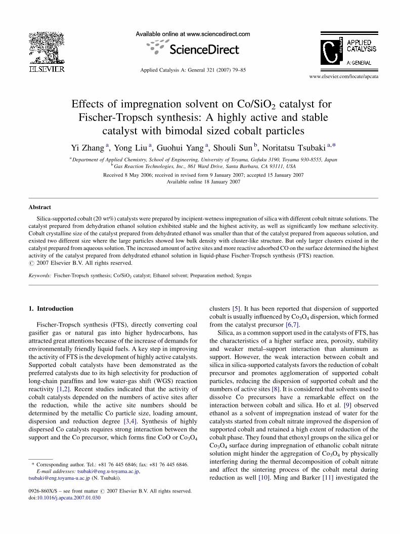
CoE was also very stable, which kept the highest activity and
low methane as well as CO2 selectivity for 100 h continuously.
But CoH was not stable. The activity with stream on time of
both kinds of catalysts was shown in Fig. 1.
3.2. The structure properties of catalysts CoE and CoH
The characterization results of CO or H2 chemisorption, O2
titration, XRD and TEM were summarized in Table 2. CoE had
the smaller cobalt crystallite size than CoH, determined by
H2ad, TEM or XRD. However, its reducibility was slightly
poorer than that of CoH. The lower reduction degree of CoE
Fig. 1. The activity and selectivity stream-on-time for CO hydrogenation over
catalyst CoH and CoE. (A) CoH and (B) CoE. Reaction conditions: 503 K,
1.0 MPa, W/F = 5 g-cat h mol�1, and H2/CO = 2.
Table 2
Characterization of catalyst CoE and CoH
Catalyst Sel. (%) CO uptake (mmol/g) Reduction degree (%) Particle size (nm) TOF (�100 s�1)
C2–C4 C5+ H2ad TEM XRD
CoH 9.8 82.7 95.7 81.9 12.1 10.7 9.2 5.4
CoE 5.2 89.2 125.4 68.8 10.7 7.5 8.7 7.5
Y. Zhang et al. / Applied Catalysis A: General 321 (2007) 79–8582
could be ascribed to the decreased polarity of the solvent, which
increased the interaction between the cobalt complex and the
silica gel surface, resulting in the formation of more cobalt
species that could only be reduced at higher temperature. The
CO uptake of CoE catalyst was larger than that of CoH,
indicating higher activity of this catalyst. The TOFs of CoE and
CoH catalysts were calculated. As shown in Table 2, the TOF of
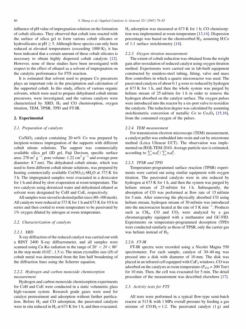
Fig. 2. TEM photos of CoE and CoH clusters.
CoE catalyst was higher than that of CoH catalyst, even though
its reduction degree was lower than that of CoH catalysts.
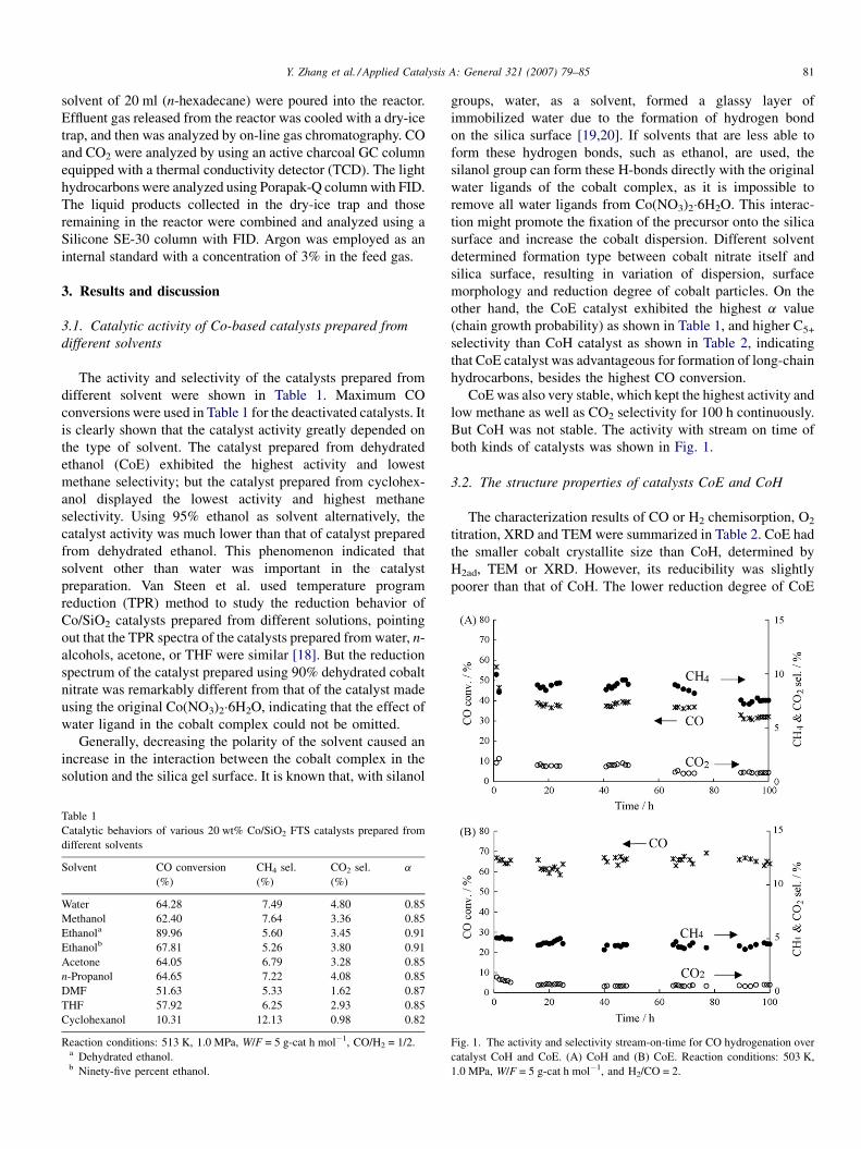
From TEM of CoH in Fig. 2, it is clear that the size of the
dispersed cobalt cluster is uniform. We counted the diameter
sizes of all the observed clusters and showed the statistical
graph in Fig. 3 for CoH. Uniformly distributed cobalt cluster
size of CoH gave a sharply concentrated distribution graph in
Fig. 3, with most clusters having size of 150 nm.
On the other hand, TEM photo of CoE in Fig. 2 distinctly
indicated that large clusters coexisted with small clusters
independently. By counting all the observed clusters, statistical
relationship between cluster size and clusters number exhibited
a dual-peak distribution for CoE in Fig. 3. Most small clusters
had a size of 40 nm while most large clusters were of 150 nm.
The TEM images in Fig. 2 showed that cobalt clusters are
smaller in CoE than in CoH. A significant difference was
observed. For CoH, the size of cobalt clusters was uniform. For
CoE, the size of cobalt clusters was bimodal. Large and small
cobalt clusters coexisted, as illustrated in Fig. 3. TEM images of
Co/SiO2 before reduction, showed the presence of droplets of
cobalt nitrate. The size of these droplets was similar to that of
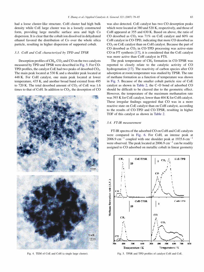
the cobalt cluster in the reduced sample [21]. Fig. 4 represents a
single cluster structure of both catalysts. For CoE, the TEM
photo of large cobalt particle is exhibited. Interestingly, the
large clusters in CoE were not in the condensed bulk state and
Fig. 3. The cobalt clusters diameter distribution of catalyst CoE and CoH.
Y. Zhang et al. / Applied Catalysis A: General 321 (2007) 79–85 83
had a loose cluster-like structure. CoH cluster had high bulk
density while CoE large cluster was in a loosely constructed
form, providing large metallic surface area and high Co
dispersion. It is clear that the cobalt ion dissolved in dehydrated
ethanol favored the distribution of Co over the whole silica
particle, resulting in higher dispersion of supported cobalt.
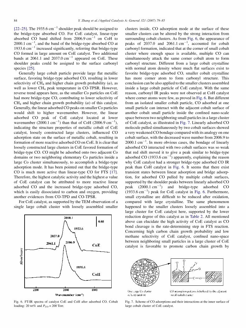
3.3. CoH and CoE characterized by TPD and TPSR
Desorption profiles of CH4, CO2 and CO on the two catalysts
measured by TPD and TPSR were described in Fig. 5. For CO-
TPD profiles, the catalyst CoE had two peaks of desorbed CO2.
The main peak located at 530 K and a shoulder peak located at
448 K. For CoH catalyst, one main peak located at lower
temperature, 435 K, and another broad band existed from 495
to 720 K. The total desorbed amount of CO2 of CoE was 1.6
times to that of CoH. In addition to CO2, the desorption of CO
Fig. 4. TEM of CoE and CoH (a single large cluster).
was also detected. CoE catalyst has two CO desorption peaks
which were located at 380 and 520 K, respectively, and those of
CoH appeared at 355 and 630 K. Based on above, the ratio of
CO desorbed as CO2 was 71% on CoE catalyst and 60% on
CoH catalyst in CO-TPD, indicating that more CO desorbed as
CO2 on CoE catalyst than on CoH catalyst. Because the part of
CO desorbed as CO2 in CO-TPD processing was active-state
CO in FT synthesis [17], it is considered that the CoE catalyst
was more active than CoH catalyst in FTS.
The peak temperature of CH4 formation in CO-TPSR was
reported to closely relate to the catalytic activity of CO
hydrogenation [17]. The reactivity of carbon species after CO
adsorption at room temperature was studied by TPSR. The rate
of methane formation as a function of temperature was shown
in Fig. 5. Because of the smaller cobalt particle size of CoE
catalyst as shown in Table 2, the C–O bond of adsorbed CO
should be difficult to be cleaved due to the geometric effect.
However, the temperature of the maximum methanation rate
was 393 K for CoE catalyst, lower than 404 K for CoH catalyst.
These irregular findings suggested that CO was in a more
reactive state on CoE catalyst than on CoH catalyst, according
to the results of CO-TPD and CO-TPSR, resulting in higher
TOF of this catalyst as shown in Table 2.
3.4. FT-IR measurement
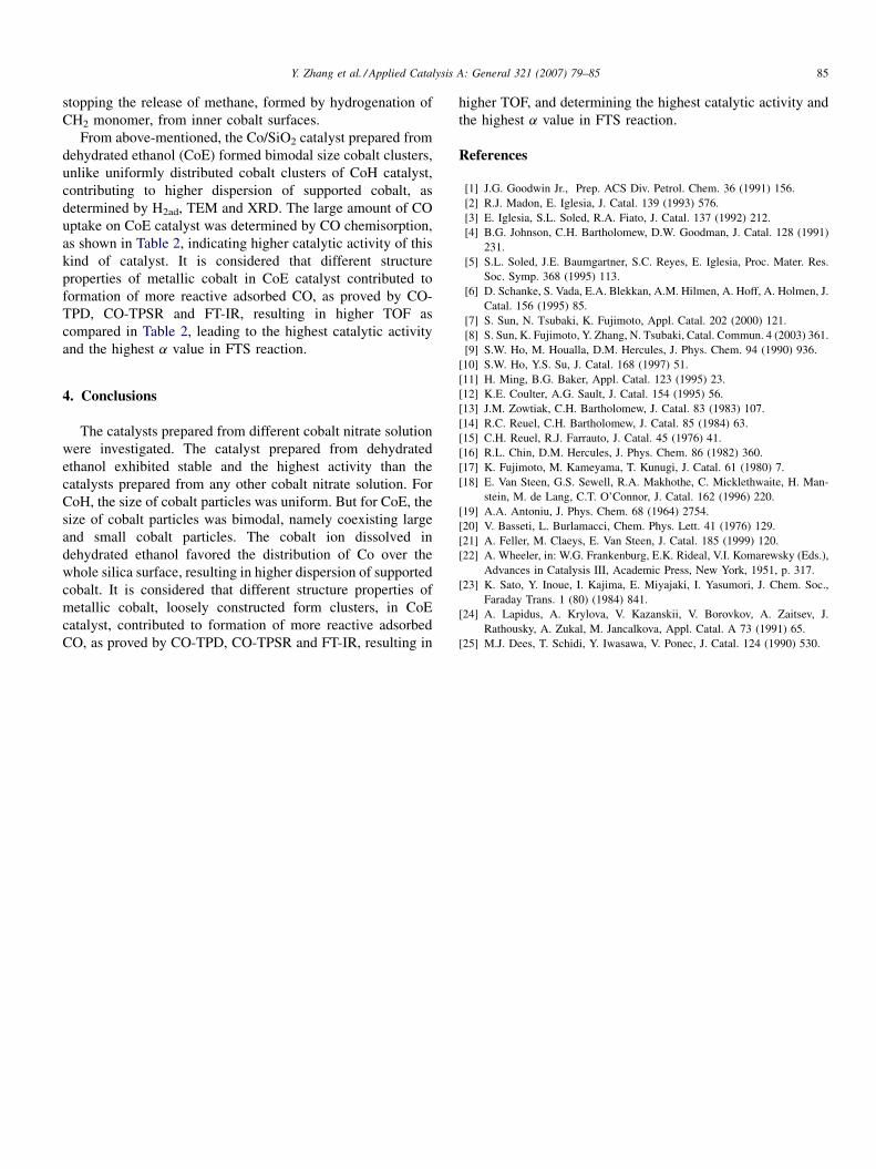
FT-IR spectra of the adsorbed CO on CoH and CoE catalysts
were compared in Fig. 6. For CoH, an intense peak at
2006.9 cm�1 coupled with one shoulder peak at 1935.6 cm�1
were observed. The peak located at 2006.9 cm�1 can be readily
assigned to CO adsorbed on metallic cobalt in linear geometry
Fig. 5. TPSR and TPD profiles of catalyst CoH and CoE.
Y. Zhang et al. / Applied Catalysis A: General 321 (2007) 79–8584
[22–25]. The 1935.6 cm�1 shoulder peak should be assigned to
the bridge-type absorbed CO. For CoE catalyst, linear-type
absorbed CO band shifted from 2006.9 cm�1 on CoH to
2000.1 cm�1, and the band of the bridge-type absorbed CO at
1933.6 cm�1 increased significantly, referring that bridge-type
CO formed in large amount on CoE catalyst. Two additional
bands at 2061.1 and 2037.0 cm�1 appeared on CoE. These
shoulder peaks could be assigned to the surface carbonyl
species [25].
Generally large cobalt particle provide large flat metallic
surface, favoring bridge-type adsorbed CO, resulting in lower
selectivity of CH4 and higher chain growth probability (a), as
well as lower CH4 peak temperature in CO-TPSR. However,
reverse trend appears here, as the smaller Co particles on CoE
had more bridge-type CO, contributing to lower selectivity of
CH4 and higher chain growth probability (a) of this catalyst.
Generally, the linear adsorbed CO peaks on smaller Co particles
would shift to higher wavenumber. However, the linear
adsorbed CO peak of CoE catalyst located at lower
wavenumber (2000.1 cm�1) than that of CoH (2006.9 cm�1),
indicating the structure properties of metallic cobalt of CoE
catalyst, loosely constructed large clusters, influenced CO
adsorption state on the surface of metallic cobalt, resulting in
formation of more reactive adsorbed CO on CoE. It is clear that
loosely constructed large clusters in CoE favored formation of
bridge-type CO. CO might be adsorbed onto two adjacent Co
domains or two neighboring elementary Co particles inside a
large Co cluster simultaneously, to accomplish a bridge-type
adsorption mode. It has been pointed out that the bridge-type
CO is much more active than linear-type CO for FTS [17].
Therefore, the highest catalytic activity and the highest a value
of CoE catalyst can be attributed to more reactive linear
adsorbed CO and the increased bridge-type adsorbed CO,
which is easily dissociated to carbon and oxygen, providing
another evidences from CO-TPD and CO-TPSR.
For CoE catalyst, as supported by the TEM observation of a
single large cobalt cluster with loosely assembled smaller
Fig. 6. FT-IR spectra of catalyst CoE and CoH after adsorbed CO. Cobalt
loading: 20 wt% and PCO = 200 Torr.
clusters inside, CO adsorption mode at the surface of these
smaller clusters can be altered by the strong interaction from
surrounding cobalt clusters. As from Fig. 6, the appearance of
peaks of 2037.0 and 2061.1 cm�1, accounted for cobalt
carbonyl formation, indicated that at the corner of small cobalt
cluster where enough space is available, multiple CO can
simultaneously attack the same corner cobalt atom to form
carbonyl structure. Different from a large cobalt crystalline
with normal atom density where much flat surfaces exist to
favorite bridge-type adsorbed CO, smaller cobalt crystalline
has more corner atom to form carbonyl structure. This
conclusion can be also applied to the smaller clusters assembled
inside a large cobalt particle of CoE catalyst. With the same
reason, carbonyl IR peaks were not observed at CoH catalyst
where corner atoms were few, as proved in Fig. 6. But different
from an isolated smaller cobalt particle, CO adsorbed at one
small particle can interact with the adjacent cobalt surface of
another cobalt small particle inside the confined nano-scale
space between two neighboring small particles in a large cluster
of CoE catalyst, as illustrated in Fig. 7. Linearly adsorbed CO
molecule pulled simultaneously by two cobalt surfaces showed
a very weakened CO bondage compared with its analogy on one
cobalt surface, with the decreased wave number from 2006.9 to
2000.1 cm�1. In more obvious cases, the bondage of linearly
adsorbed CO interacted with two cobalt surfaces was so weak
that red shift moved it to give a peak similar to bridge-type
adsorbed CO (1933.6 cm�1) apparently, explaining the reason
why CoE catalyst had a stronger bridge-type adsorbed CO IR
peak than CoH catalyst in Fig. 6. It seems that there exist
transient states between linear adsorption and bridge adsorp-
tion, for adsorbed CO pulled by multiple cobalt surfaces,
supported by the shoulder peaks between linearly adsorbed CO
peak (2000.1 cm�1) and bridge-type adsorbed CO
(1933.6 cm�1) peak for CoE catalyst in Fig. 6. Furthermore,
small crystalline are difficult to be reduced after oxidation,
compared with large crystalline. The same phenomenon
happened to the smaller clusters loosely assembled into a
large cluster for CoE catalyst here, supported by the lower
reduction degree of this catalyst as in Table 2. All mentioned
above can elucidate the high activity of CoE catalyst as CO
bond cleavage is the rate-determining step in FTS reaction.
Concerning high carbon chain growth probability and low
methane selectivity of CoE catalyst, confined nano-space
between neighboring small particles in a large cluster of CoE
catalyst is favorable to promote carbon chain growth by
Fig. 7. Scheme of CO adsorptions and their interactions at the inner surface of
large cobalt cluster of CoE catalyst.
Y. Zhang et al. / Applied Catalysis A: General 321 (2007) 79–85 85
stopping the release of methane, formed by hydrogenation of
CH2 monomer, from inner cobalt surfaces.
From above-mentioned, the Co/SiO2 catalyst prepared from
dehydrated ethanol (CoE) formed bimodal size cobalt clusters,
unlike uniformly distributed cobalt clusters of CoH catalyst,
contributing to higher dispersion of supported cobalt, as
determined by H2ad, TEM and XRD. The large amount of CO
uptake on CoE catalyst was determined by CO chemisorption,
as shown in Table 2, indicating higher catalytic activity of this
kind of catalyst. It is considered that different structure
properties of metallic cobalt in CoE catalyst contributed to
formation of more reactive adsorbed CO, as proved by CO-
TPD, CO-TPSR and FT-IR, resulting in higher TOF as
compared in Table 2, leading to the highest catalytic activity
and the highest a value in FTS reaction.
4. Conclusions
The catalysts prepared from different cobalt nitrate solution
were investigated. The catalyst prepared from dehydrated
ethanol exhibited stable and the highest activity than the
catalysts prepared from any other cobalt nitrate solution. For
CoH, the size of cobalt particles was uniform. But for CoE, the
size of cobalt particles was bimodal, namely coexisting large
and small cobalt particles. The cobalt ion dissolved in
dehydrated ethanol favored the distribution of Co over the
whole silica surface, resulting in higher dispersion of supported
cobalt. It is considered that different structure properties of
metallic cobalt, loosely constructed form clusters, in CoE
catalyst, contributed to formation of more reactive adsorbed
CO, as proved by CO-TPD, CO-TPSR and FT-IR, resulting in
higher TOF, and determining the highest catalytic activity and
the highest a value in FTS reaction.
References
[1] J.G. Goodwin Jr., Prep. ACS Div. Petrol. Chem. 36 (1991) 156.
[2] R.J. Madon, E. Iglesia, J. Catal. 139 (1993) 576.
[3] E. Iglesia, S.L. Soled, R.A. Fiato, J. Catal. 137 (1992) 212.
[4] B.G. Johnson, C.H. Bartholomew, D.W. Goodman, J. Catal. 128 (1991)
231.
[5] S.L. Soled, J.E. Baumgartner, S.C. Reyes, E. Iglesia, Proc. Mater. Res.
Soc. Symp. 368 (1995) 113.
[6] D. Schanke, S. Vada, E.A. Blekkan, A.M. Hilmen, A. Hoff, A. Holmen, J.
Catal. 156 (1995) 85.
[7] S. Sun, N. Tsubaki, K. Fujimoto, Appl. Catal. 202 (2000) 121.
[8] S. Sun, K. Fujimoto, Y. Zhang, N. Tsubaki, Catal. Commun. 4 (2003) 361.
[9] S.W. Ho, M. Houalla, D.M. Hercules, J. Phys. Chem. 94 (1990) 936.
[10] S.W. Ho, Y.S. Su, J. Catal. 168 (1997) 51.
[11] H. Ming, B.G. Baker, Appl. Catal. 123 (1995) 23.
[12] K.E. Coulter, A.G. Sault, J. Catal. 154 (1995) 56.
[13] J.M. Zowtiak, C.H. Bartholomew, J. Catal. 83 (1983) 107.
[14] R.C. Reuel, C.H. Bartholomew, J. Catal. 85 (1984) 63.
[15] C.H. Reuel, R.J. Farrauto, J. Catal. 45 (1976) 41.
[16] R.L. Chin, D.M. Hercules, J. Phys. Chem. 86 (1982) 360.
[17] K. Fujimoto, M. Kameyama, T. Kunugi, J. Catal. 61 (1980) 7.
[18] E. Van Steen, G.S. Sewell, R.A. Makhothe, C. Micklethwaite, H. Man-
stein, M. de Lang, C.T. O’Connor, J. Catal. 162 (1996) 220.
[19] A.A. Antoniu, J. Phys. Chem. 68 (1964) 2754.
[20] V. Basseti, L. Burlamacci, Chem. Phys. Lett. 41 (1976) 129.
[21] A. Feller, M. Claeys, E. Van Steen, J. Catal. 185 (1999) 120.
[22] A. Wheeler, in: W.G. Frankenburg, E.K. Rideal, V.I. Komarewsky (Eds.),
Advances in Catalysis III, Academic Press, New York, 1951, p. 317.
[23] K. Sato, Y. Inoue, I. Kajima, E. Miyajaki, I. Yasumori, J. Chem. Soc.,
Faraday Trans. 1 (80) (1984) 841.
[24] A. Lapidus, A. Krylova, V. Kazanskii, V. Borovkov, A. Zaitsev, J.
Rathousky, A. Zukal, M. Jancalkova, Appl. Catal. A 73 (1991) 65.
[25] M.J. Dees, T. Schidi, Y. Iwasawa, V. Ponec, J. Catal. 124 (1990) 530.