Embed Size (px)
Citation preview
ARTICLE IN PRESS
Tribology International 42 (2009) 311–319
Contents lists available at ScienceDirect
Tribology International
0301-67
doi:10.1
� Corr
Gyeong
701, Rep
E-m
journal homepage: www.elsevier.com/locate/triboint
Effects of friction laws on metal forming processes
M.S. Joun a,b,�, H.G. Moon c, I.S. Choi d, M.C. Lee d, B.Y. Jun d
a School of Mechanical and Aerospace Engineering, Gyeongsang National University, 900 Gazwa-dong, Jinju-City, GyeongNam 660-701, Republic of Koreab Research Center for Aircraft Parts Technology, Gyeongsang National University, Republic of Koreac FAG Schaeffler Korea Corporation, R&D Center, Republic of Koread Department of Mechanical Engineering, Gyeongsang National University, Republic of Korea
a r t i c l e i n f o
Article history:
Received 20 August 2007
Received in revised form
19 June 2008
Accepted 24 June 2008Available online 26 July 2008
Keywords:
Bulk metal forming
Friction law
Friction-sensitive metal forming process
Coulomb friction law
Constant shear friction law
9X/$ - see front matter & 2008 Elsevier Ltd. A
016/j.triboint.2008.06.012
esponding author at: School of Mechanical
sang National University, 900 Gazwa-dong,
ublic of Korea. Tel./fax: +82 55 7515316.
ail address: [email protected] (M.S. Joun).
a b s t r a c t
In this paper, the Coulomb friction law and the constant shear friction law were compared and
investigated in detail using a rigid-plastic finite element method with emphasis on their application in
bulk metal forming. The ring compression test for two different materials was used to evaluate the two
friction laws, and then their effects on metal flow lines and forming loads for various friction-sensitive
metal forming processes including strip rolling, ring gear forging, multistep extrusion, and pipe
shrinkage and expansion were investigated. It was shown that considerable differences exist between
the two friction laws, especially in friction-sensitive metal forming processes.
& 2008 Elsevier Ltd. All rights reserved.
1. Introduction
Friction is a major factor in determining the characteristics ofmetals as they are formed. Friction is essential in rolling becausethe friction force maintains equilibrium against the backwardpush force caused by the roll-separating force at the roll bite.However, excessive friction in rolling increases the roll-separatingforce and accelerates roller wear. In forging, friction is a key factorin the pattern of metal flow and die wear. In general, excessivefriction has a negative influence on die wear, product quality,product cost, and productivity. It is therefore common to usevarious lubricants to reduce friction during the formation ofmetals.
Major factors affecting friction include the normal stress alongthe die–material interface, the lubrication condition, the relativevelocity, the temperature, the roughness, and the mechanicalproperties of the material and/or the die. A detailed investigationof these factors is not easy because the die–material interface inmetal forming is under high pressure and temperature. Thus,friction in this area is still somewhat of a mystery even thoughmany researchers have studied on it in various ways for a longtime. For an example, the friction in hot rolling [1–4] is extremely
ll rights reserved.
and Aerospace Engineering,
Jinju-City, GyeongNam 660-
complex because it depends on various parameters includingoxide scale, material composition, temperature and the like.
In metal forming simulations, friction has traditionally beenassumed to follow the Coulomb friction law [5–14] and theconstant shear friction law [15–20]. Several variations [21–25] ofthese laws have been developed.
According to the Coulomb friction law, the frictional stress isproportional to the normal stress or force, while the constantshear friction law states that the frictional stress is a certainfraction of the shear yield stress of the material, and does notreflect the effects of the normal stress on the frictional stress. It isclear that frictional stress is related to the normal stress, and thatthe Coulomb friction law or its variants can describe the realbehavior of friction better than the constant shear friction law.However, the constant shear friction law has been widely used insimulations of bulk metal forming due to its theoretical simplicityand numerical rigidity. At room temperature, the two laws givenearly the same results for ring compression because the normalstress distribution in this case is relatively uniform over thecontact area even though ring compression itself is very friction-sensitive. Since the normal stress variation along the die–materialinterface for rod drawing and streamlined die extrusion isrelatively small, the two friction laws predict similar results forthose cases. However, for rolling and complex forging in which thenormal stress may vary widely across the die–material interface,the two friction laws may give results that are quite different.
Friction dominates not only the material flow, but also the diewear. Despite the importance of the friction law, it is hard to find
ARTICLE IN PRESS
60
70
Coulomb frictionConstant shear frictionet
er,
m = 0.60µ = 0.24
m = 0.50
M.S. Joun et al. / Tribology International 42 (2009) 311–319312
studies on the subject. In this study, we used a rigid-viscoplasticfinite element method to analyze the Coulomb friction law andthe constant shear friction law to compare the results of severalfriction-sensitive metal forming processes.
0 10 20 30 40 50 60-30
-20
-10
0
10
20
30
40
50
Red
uctio
n in
min
imum
inte
rnal
dia
md 0
-dd 0
X 10
0%
h0
h0-hReduction in height, X 100%
m = 0.10
µ = 0.04
m = 0.20
µ = 0.08
m = 0.30µ = 0.12
µ = 0.16m = 0.40
µ = 0.20
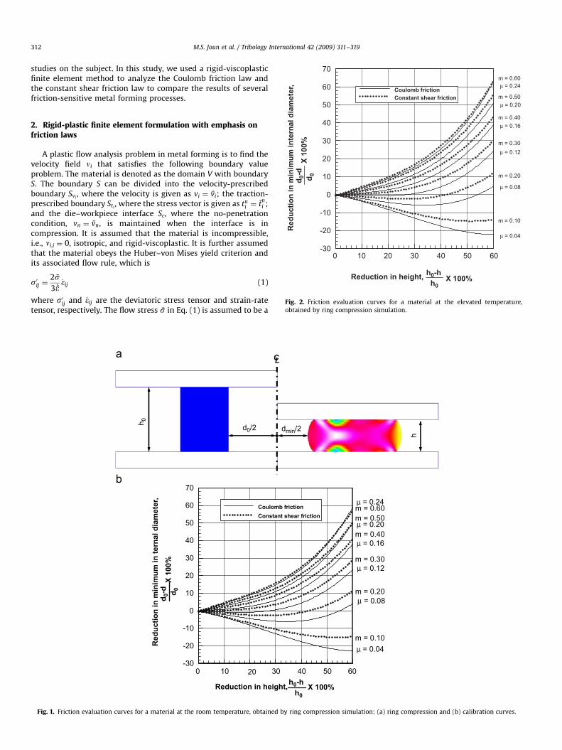
Fig. 2. Friction evaluation curves for a material at the elevated temperature,
obtained by ring compression simulation.
2. Rigid-plastic finite element formulation with emphasis onfriction laws
A plastic flow analysis problem in metal forming is to find thevelocity field ni that satisfies the following boundary valueproblem. The material is denoted as the domain V with boundaryS. The boundary S can be divided into the velocity-prescribedboundary Svi
, where the velocity is given as vi ¼ v̄i; the traction-prescribed boundary Sti
, where the stress vector is given as tni ¼ t̄
ni ;
and the die–workpiece interface Sc, where the no-penetrationcondition, vn ¼ v̄n, is maintained when the interface is incompression. It is assumed that the material is incompressible,i.e., ni,i ¼ 0, isotropic, and rigid-viscoplastic. It is further assumedthat the material obeys the Huber–von Mises yield criterion andits associated flow rule, which is
s0ij ¼2s̄3 _̄�
_�ij (1)
where s0ij and _�ij are the deviatoric stress tensor and strain-ratetensor, respectively. The flow stress s̄ in Eq. (1) is assumed to be a
h 0 d0/2 dmin/2
CL
h
0 10 20 30 40 50 60-30
-20
-10
0
10
20
30
40
50
60
70
Coulomb frictionConstant shear friction
Red
uctio
n in
min
imum
in te
rnal
dia
met
er,
d 0-d d 0
X 10
0%
h0
h0-hReduction in height, X 100%
m = 0.60µ = 0.24
m = 0.10µ = 0.04
m = 0.20µ = 0.08
m = 0.30µ = 0.12
µ = 0.16m = 0.40
m = 0.50µ = 0.20
Fig. 1. Friction evaluation curves for a material at the room temperature, obtained by ring compression simulation: (a) ring compression and (b) calibration curves.

ARTICLE IN PRESS
Fig. 3. Comparison of metal flow lines formed from compression of the ring with
small aspect ratio and small ratio of contact region: (a) Coulomb friction law and
(b) constant shear frictional law.
Stroke (mm)
Load
(kN
)
0 10 20 30 40 50 60 700
20
40
60
80
100
120
140
Coulomb friction lawConstant shear friction law
Fig. 4. Stroke-forming load curves of the ring compression with small aspect ratio
and small ratio of contact region.
Fig. 5. Comparison of metal flow lines formed from compression of the ring with
large aspect ratio and large ratio of contact region: (a) Coulomb friction law and (b)
constant shear friction law.
M.S. Joun et al. / Tribology International 42 (2009) 311–319 313
function of the effective strain �̄ and the effective strain rate _̄�, i.e.,s̄ ¼ s̄ð�̄; _̄�Þ. It is also assumed that the effect of accelerationand gravity on force equilibrium is negligible, and that theprocess is isothermal. Thus, the equation of equilibrium can bewritten as
sij;j þ f i ¼ 0 (2)
ARTICLE IN PRESS
Load
(kN
)
0 5 10 15 20 250
150
300
450
600
750
Coulomb frictionConstant shear friction
Stroke (mm)
Fig. 6. Stroke-forming load curves of the ring compression with large aspect ratio
and large ratio of contact region.
0 1-20
-10
0
10
20
30
40µ = 0.1µ = 0.2µ = 0.3µ = 0.4µ = 0.5µ = 0.6µ = 0.7m = 1.0
v tv t
x 10
0|vt|
Roll
Strip
Normalized angle of contact (�/�max)0.2 0.4 0.6 0.8
�max
�
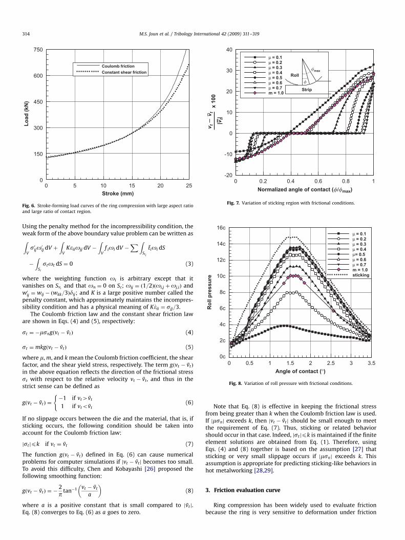
Fig. 7. Variation of sticking region with frictional conditions.
Rol
l pre
ssur
e
0 1 2 3
µ = 0.1µ = 0.2µ = 0.3µ = 0.4µ= 0.5µ = 0.6µ = 0.7m = 1.0sticking
16c
14c
12c
10c
8c
6c
4c
2c
0c
Angle of contact (°)0.5 1.5 2.5 3.5
Fig. 8. Variation of roll pressure with frictional conditions.
M.S. Joun et al. / Tribology International 42 (2009) 311–319314
Using the penalty method for the incompressibility condition, theweak form of the above boundary value problem can be written asZ
Vs0ijo
0ij dV þ
ZV
K�iiojj dV �
ZV
f ioi dV �XZ
Sti
t̄ioi dS
�
ZSc
stot dS ¼ 0 (3)
where the weighting function oi is arbitrary except that itvanishes on Svi
and that on ¼ 0 on Sc; oij ¼ ð1=2Þðoi;j þoj;iÞ andw0ij ¼ wij � ðwkk=3Þdij; and K is a large positive number called thepenalty constant, which approximately maintains the incompres-sibility condition and has a physical meaning of K _�ii ¼ sjj=3.
The Coulomb friction law and the constant shear friction laware shown in Eqs. (4) and (5), respectively:
st ¼ �msngðvt � v̄tÞ (4)
st ¼ mkgðvt � v̄tÞ (5)
where m, m, and k mean the Coulomb friction coefficient, the shearfactor, and the shear yield stress, respectively. The term gðvt � v̄tÞ
in the above equation reflects the direction of the frictional stressst with respect to the relative velocity vt � v̄t, and thus in thestrict sense can be defined as
gðvt � v̄tÞ ¼�1 if vt4v̄t
1 if vtov̄t
((6)
If no slippage occurs between the die and the material, that is, ifsticking occurs, the following condition should be taken intoaccount for the Coulomb friction law:
jstjpk if vt ¼ v̄t (7)
The function gðvt � v̄tÞ defined in Eq. (6) can cause numericalproblems for computer simulations if jvt � v̄tj becomes too small.To avoid this difficulty, Chen and Kobayashi [26] proposed thefollowing smoothing function:
gðvt � v̄tÞ ¼ �2
p tan�1 vt � v̄t
a
� �(8)
where a is a positive constant that is small compared to jv̄tj.Eq. (8) converges to Eq. (6) as a goes to zero.
Note that Eq. (8) is effective in keeping the frictional stressfrom being greater than k when the Coulomb friction law is used.If jmsnj exceeds k, then jvt � v̄t j should be small enough to meetthe requirement of Eq. (7). Thus, sticking or related behaviorshould occur in that case. Indeed, jstjpk is maintained if the finiteelement solutions are obtained from Eq. (1). Therefore, usingEqs. (4) and (8) together is based on the assumption [27] thatsticking or very small slippage occurs if jmsnj exceeds k. Thisassumption is appropriate for predicting sticking-like behaviors inhot metalworking [28,29].
3. Friction evaluation curve
Ring compression has been widely used to evaluate frictionbecause the ring is very sensitive to deformation under friction

ARTICLE IN PRESS
Fig. 9. Variation of metal flow lines with the two frictional laws: (a) Coulomb friction law and (b) constant shear friction law.
Fig. 10. Detailed comparison of metal flow lines: (a) Coulomb friction law and (b)
constant shear friction law.
Load
(kN
)
10 20 30 40 500
2000
4000
6000
8000
10000
12000
Coulomb frictionConstant shear friction
Stroke (mm)
Fig. 11. Comparison of forming loads in the ring gear forging, predicted by the two
different frictional laws.
M.S. Joun et al. / Tribology International 42 (2009) 311–319 315
conditions [10,30–34]. Specifically, the inner and outer radii of thedeformed ring vary with respect to its height, and the deformationpattern is highly dependent on the friction conditions. Through
finite element analysis, one can construct the friction evaluationcurves by plotting the minimum ring radius versus height. Forexample, Fig. 1 shows the friction evaluation curves for a material

ARTICLE IN PRESS
CL
Punch
0.71.0
0.7
0.5
0.30.1
� = 0.02
0.04
0.06
1.0
0.7
0.5
0.30.7
0.1
� = 0.1
Plasticregion
M.S. Joun et al. / Tribology International 42 (2009) 311–319316
with a flow stress of s̄ ¼ 50:3ð1þ �̄=0:05Þ0:26 MPa. Thus, ringcompression tests can be used to estimate the Coulomb frictioncoefficient or friction factor by comparing the experimental curveof the minimum ring radius versus height to the theoreticalfriction evaluation curves.
Note that the initial ratio of the outer diameter to the innerdiameter to the height of the ring is 6:3:2.
Fig. 1 shows a set of friction evaluation curves at roomtemperature and Fig. 2 shows the same curves for a material at anelevated temperature, where the flow stress is s̄ ¼ 66:0 _̄�
0:195MPa.
To obtain Fig. 2, we used the following conditions: initial outerdiameter of the ring, 60 mm; height of the ring, 40 mm; punchvelocity, �200 mm/s; and reduction ratio, 60%.
Comparing the slopes of the curves in Figs. 1 and 2 show thatthe Coulomb friction law and the constant shear friction lawproduce nearly the same results, especially for a smaller reductionand lower friction. However, as friction and reduction increase,the difference in the slope of the friction evaluation curvesincreases. This is because the Coulomb friction law reflects thenormal stress variation at high friction and high reduction, whilethe constant shear friction law does not.
Die 1.0
0.08
1.0
Fig. 12. Variation of plastic region and effective strain with the Coulomb friction
coefficients: (a) variant Coulomb friction coefficient and (b) constant Coulomb
friction coefficient.
Gapl
d
CL
CL
Fig. 13. A long-pipe simultaneously shrinking and expanding process: (a) initial
and (b) final.
4. Effects of friction laws and conditions
The aspect ratio of the process is defined as the width of thematerial divided by its height. The ratio of the contact region isthe area of the die–material interface divided by the entire surfacearea of the material.
4.1. Low aspect ratio cylinder compression
Fig. 3 shows the predicted results of metal flow lines formed bycompressing a cylinder with a relatively low aspect ratio and alow contact ratio. The process information used for the simulationwas the same as that for obtaining the friction evaluation curvesin Fig. 2. Fig. 3(a) shows the results obtained with m ¼ 0.2, whileFig. 3(b) gives the results for m ¼ 0.48. The friction factorm ¼ 0.48 corresponds closely to the Coulomb friction coefficientof m ¼ 0.2 shown in Fig. 2. The metal flow lines in Fig. 3 indicatethat the Coulomb friction law and the constant shear friction lawpredict very similar results when the aspect ratio and the contactratio are both small. This can also be seen in the forming loadcurves in Fig. 4.
4.2. Compression of a cylinder with a large aspect ratio
The process information to simulate the compression of acylinder is same as that used to obtain the friction evaluationcurves in Fig. 2. Figs. 5 and 6 show the analysis results of a cylindercompression process when the aspect ratio of the cylinder isrelatively large. Fig. 5(a) shows the results obtained with m ¼ 0.2while Fig. 5(b) gives the results for m ¼ 0.48. Fig. 6 showsthe variation of forming load. Together, these figures indicatethat the results are nearly the same in the beginning stroke butthat differences in both metal flow lines and forming loadsbecome more pronounced as the stroke proceeds. This impliesthat the difference between the two friction laws increases asthe aspect ratio of the material and the contact ratio of the regionincrease.
4.3. Hot strip rolling
Hot strip rolling is a representative example of a process with alarge aspect ratio and a large contact ratio. Thus, it is the extreme
ARTICLE IN PRESS
�� = 0.05 m = 0.096
� = 0.75 m = 0.153
� = 0.25 m = 0.43
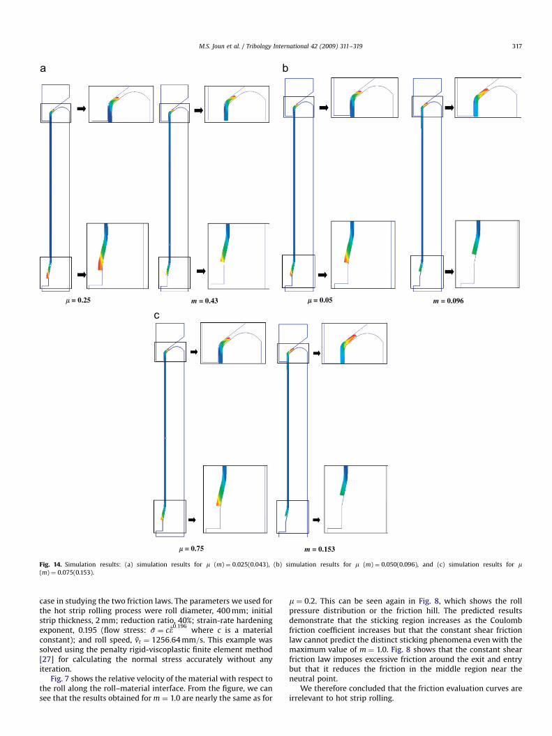
Fig. 14. Simulation results: (a) simulation results for m (m) ¼ 0.025(0.043), (b) simulation results for m (m) ¼ 0.050(0.096), and (c) simulation results for m(m) ¼ 0.075(0.153).
M.S. Joun et al. / Tribology International 42 (2009) 311–319 317
case in studying the two friction laws. The parameters we used forthe hot strip rolling process were roll diameter, 400 mm; initialstrip thickness, 2 mm; reduction ratio, 40%; strain-rate hardeningexponent, 0.195 (flow stress: s̄ ¼ c _̄�
0:196where c is a material
constant); and roll speed, v̄t ¼ 1256:64 mm=s. This example wassolved using the penalty rigid-viscoplastic finite element method[27] for calculating the normal stress accurately without anyiteration.
Fig. 7 shows the relative velocity of the material with respect tothe roll along the roll–material interface. From the figure, we cansee that the results obtained for m ¼ 1.0 are nearly the same as for
m ¼ 0.2. This can be seen again in Fig. 8, which shows the rollpressure distribution or the friction hill. The predicted resultsdemonstrate that the sticking region increases as the Coulombfriction coefficient increases but that the constant shear frictionlaw cannot predict the distinct sticking phenomena even with themaximum value of m ¼ 1.0. Fig. 8 shows that the constant shearfriction law imposes excessive friction around the exit and entrybut that it reduces the friction in the middle region near theneutral point.
We therefore concluded that the friction evaluation curves areirrelevant to hot strip rolling.
ARTICLE IN PRESS
0
Nos
e le
ngth
(mm
)0
0
10
20
30
40
Coulomb frictionConstant shear friction
Coefficient of Coulomb friction0.10.0750.050.025
0.2140.1530.0960.043Friction factor
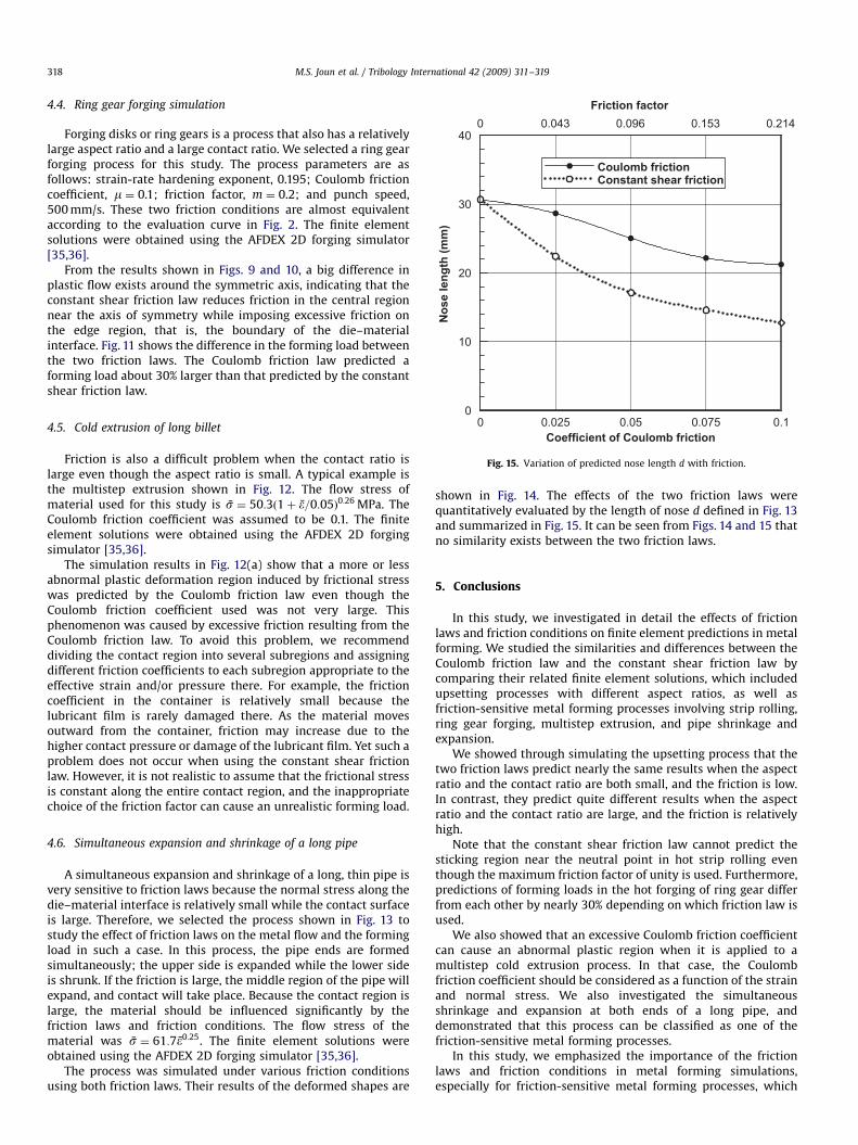
Fig. 15. Variation of predicted nose length d with friction.
M.S. Joun et al. / Tribology International 42 (2009) 311–319318
4.4. Ring gear forging simulation
Forging disks or ring gears is a process that also has a relativelylarge aspect ratio and a large contact ratio. We selected a ring gearforging process for this study. The process parameters are asfollows: strain-rate hardening exponent, 0.195; Coulomb frictioncoefficient, m ¼ 0.1; friction factor, m ¼ 0.2; and punch speed,500 mm/s. These two friction conditions are almost equivalentaccording to the evaluation curve in Fig. 2. The finite elementsolutions were obtained using the AFDEX 2D forging simulator[35,36].
From the results shown in Figs. 9 and 10, a big difference inplastic flow exists around the symmetric axis, indicating that theconstant shear friction law reduces friction in the central regionnear the axis of symmetry while imposing excessive friction onthe edge region, that is, the boundary of the die–materialinterface. Fig. 11 shows the difference in the forming load betweenthe two friction laws. The Coulomb friction law predicted aforming load about 30% larger than that predicted by the constantshear friction law.
4.5. Cold extrusion of long billet
Friction is also a difficult problem when the contact ratio islarge even though the aspect ratio is small. A typical example isthe multistep extrusion shown in Fig. 12. The flow stress ofmaterial used for this study is s̄ ¼ 50:3ð1þ �̄=0:05Þ0:26 MPa. TheCoulomb friction coefficient was assumed to be 0.1. The finiteelement solutions were obtained using the AFDEX 2D forgingsimulator [35,36].
The simulation results in Fig. 12(a) show that a more or lessabnormal plastic deformation region induced by frictional stresswas predicted by the Coulomb friction law even though theCoulomb friction coefficient used was not very large. Thisphenomenon was caused by excessive friction resulting from theCoulomb friction law. To avoid this problem, we recommenddividing the contact region into several subregions and assigningdifferent friction coefficients to each subregion appropriate to theeffective strain and/or pressure there. For example, the frictioncoefficient in the container is relatively small because thelubricant film is rarely damaged there. As the material movesoutward from the container, friction may increase due to thehigher contact pressure or damage of the lubricant film. Yet such aproblem does not occur when using the constant shear frictionlaw. However, it is not realistic to assume that the frictional stressis constant along the entire contact region, and the inappropriatechoice of the friction factor can cause an unrealistic forming load.
4.6. Simultaneous expansion and shrinkage of a long pipe
A simultaneous expansion and shrinkage of a long, thin pipe isvery sensitive to friction laws because the normal stress along thedie–material interface is relatively small while the contact surfaceis large. Therefore, we selected the process shown in Fig. 13 tostudy the effect of friction laws on the metal flow and the formingload in such a case. In this process, the pipe ends are formedsimultaneously; the upper side is expanded while the lower sideis shrunk. If the friction is large, the middle region of the pipe willexpand, and contact will take place. Because the contact region islarge, the material should be influenced significantly by thefriction laws and friction conditions. The flow stress of thematerial was s̄ ¼ 61:7�̄0:25. The finite element solutions wereobtained using the AFDEX 2D forging simulator [35,36].
The process was simulated under various friction conditionsusing both friction laws. Their results of the deformed shapes are
shown in Fig. 14. The effects of the two friction laws werequantitatively evaluated by the length of nose d defined in Fig. 13and summarized in Fig. 15. It can be seen from Figs. 14 and 15 thatno similarity exists between the two friction laws.
5. Conclusions
In this study, we investigated in detail the effects of frictionlaws and friction conditions on finite element predictions in metalforming. We studied the similarities and differences between theCoulomb friction law and the constant shear friction law bycomparing their related finite element solutions, which includedupsetting processes with different aspect ratios, as well asfriction-sensitive metal forming processes involving strip rolling,ring gear forging, multistep extrusion, and pipe shrinkage andexpansion.
We showed through simulating the upsetting process that thetwo friction laws predict nearly the same results when the aspectratio and the contact ratio are both small, and the friction is low.In contrast, they predict quite different results when the aspectratio and the contact ratio are large, and the friction is relativelyhigh.
Note that the constant shear friction law cannot predict thesticking region near the neutral point in hot strip rolling eventhough the maximum friction factor of unity is used. Furthermore,predictions of forming loads in the hot forging of ring gear differfrom each other by nearly 30% depending on which friction law isused.
We also showed that an excessive Coulomb friction coefficientcan cause an abnormal plastic region when it is applied to amultistep cold extrusion process. In that case, the Coulombfriction coefficient should be considered as a function of the strainand normal stress. We also investigated the simultaneousshrinkage and expansion at both ends of a long pipe, anddemonstrated that this process can be classified as one of thefriction-sensitive metal forming processes.
In this study, we emphasized the importance of the frictionlaws and friction conditions in metal forming simulations,especially for friction-sensitive metal forming processes, which

ARTICLE IN PRESS
M.S. Joun et al. / Tribology International 42 (2009) 311–319 319
have aspect ratios that are larger or smaller than normallyencountered.
Acknowledgment
This study was supported by Grant no. RTI04-01-03 from theRegional Technology Innovation Program of the Republic of KoreaMinistry of Commerce, Industry and Energy.
References
[1] Munther PA, Lenard G. Tribology during hot, flat rolling of steels. Ann CIRP1995;44:213–6.
[2] Kryzanowski M, Beynon JH. Modelling the boundary conditions for thermo—
mechanical process—oxide scale behaviour and composition effects. ModelSimul Mater Sci Eng 2000;8:927–45.
[3] Kryzanowski M, Beynon JH. Modelling the behaviour of oxide scale in hotrolling. ISIJ Int 2006;46:1533–47.
[4] Lenard JG, Barbulov-Nad L. The coefficient of friction during hot rolling of lowcarbon steel strips. ASME Trans J Tribol 2002;124(4):840–5.
[5] Zienkiewicz OC, Jain PC, Onate E. Flow of solids during forming and extrusion:some aspects of numerical solutions. Int J Solids Struct 1978;14:15–38.
[6] Tran DV, Lewis RW, Gethin DT, Afriffin AK. Numerical modelling of powdercompaction processes: displacement based finite element method. PowderMetall 1993;36:257–66.
[7] Li GJ, Kobayashi S. Rigid plastic finite element analysis of plane strain rolling.ASME Trans J Eng Ind 1982;104:55–64.
[8] Hirai T, Ishise T. Plastic metal flow under frictional boundary in forwardextrusion die and stress distribution of the die. Int J Mach Tool Des Res1986;26:217–29.
[9] Mori K, Osakada K. Finite element simulation of three-dimensional deforma-tion in shape rolling. Int J Numer Methods Eng 1990;30:1431–40.
[10] Hwang SM, Joun MS, Park JS. A penalty rigid-plastic finite element method forthe determination of stress distributions at the tool–workpiece interface inmetal forming. Trans NAMRI SME 1990;18:13–9.
[11] Hwang SM, Joun MS, Kang YH. Finite element analysis of temperatures, metalflow, and roll pressure in hot strip rolling. ASME Trans J Eng Ind 1993;115:290–8.
[12] Joun MS, Hwang SM. Die shape optimal design in three-dimensional shapemetal extrusion by the finite element method. Int J Numer Methods Eng1998;41:311–35.
[13] Joun MS. Iterative and non-iterative schemes for coulomb frictional law inmetal forming simulation and their numerical characteristics. CommunNumer Methods Eng 1999;15(7):515–25.
[14] Fedorciuc-Onisa C, Farrugia DCJ. Simulation of frictional conditions duringlong product hot rolling. The 6th ESAFORM conference on material forming,2003. p. 763–766.
[15] Lee CH, Kobayashi S. New solutions to rigid-plastic deformation problemsusing a matrix method. ASME Trans J Eng Ind 1973;95:865–73.
[16] Park JJ, Oh SI. Application of three dimensional finite element analysis ofshape rolling processes. ASME Trans J Eng Ind 1990;112:34–46.
[17] Coupez T, Soyris N, Chenot JL. 3-d finite element modeling of the forg-ing process with automatic remeshing. J Mater Proc Technol 1991;27:119–33.
[18] Cho JR, Park CY, Yang DY. Investigation of the cogging processes by three-dimensional thermo-viscoplastic finite element analysis. Proc Inst Mech Eng1992;206:277–86.
[19] Oh SI, Wu WT, Tang JP. Simulations of cold forging processes by the DEFORMsystem. J Mater Proc Technol 1992;35:357–70.
[20] Sivaprasad PV, Davies CHJ. An assessment of the interface friction factor usingthe geometry of upset specimens. Model Simul Mater Sci Eng 2005;13:355–60.
[21] Petersen SB, Martins PAF, Bay N. Friction in bulk metal forming: a generalfriction model vs. the law of constant friction. J Mater Proc Technol 1997;66:186–94.
[22] Tan X. Comparison of friction models in bulk metal forming. Tribol Int2002;35:385–93.
[23] Lebon F. Contact problems with friction: models and simulations. SimulModel Pract Theory 2003;11:229–463.
[24] Fereshteh-Saniee F. Friction modelling for the physical simulation of the bulkmetal forming processes. J Mater Proc Technol 2004;153–154:151–6.
[25] Fedorciuc-Onisa C, Farrugia DCJ. Through process characterisation offrictional conditions under lubrication for long product hot rolling. Steelrolling 2006—9th international and 4th European conferences, Paris, June2006. p. 19–21.
[26] Chen CC, Kobayashi S. Rigid plastic finite element analysis of ringcompression. ASME Pubrication AMD 1978;28:163–74.
[27] Hwang SM, Joun MS. Analysis of hot strip rolling by a penalty rigid-visoplasticfinite element method. Int J Mech Sci 1992;34(12):971–84.
[28] Orowan E. The calculation of roll pressure in hot and cold flat rolling. Proc InstMech Eng 1944;150:140–67.
[29] Thomsen EG, Yang CT, Kobayashi S. Mechanics of plastic deformation in metalforming process. New York: Macmillan; 1965.
[30] Hawkyard JB, Johnson W. An analysis of the changes in geometry of ashort hollow cylinder during axial compression. Int J Mech Sci 1967;9:163–82.
[31] Male AT, Depierre V. The validity of mathematical solutions for determiningfriction from the ring compression test. ASME Trans J Lubr Technol1970;92(2):389–97.
[32] Lee CH, Altan T. Influence of flow stress and friction upon metal flow in upsetforging of rings and cylinders. ASME Trans J Eng Ind 1972;94(3):775–85.
[33] Hwang SM, Kobayashi S. A note on evaluation of interface friction in ringtests. In: Proceedings of the XIth NAMRC, SME, 1983, p. 193–196.
[34] Park CY, Yang DY. Effects of work-hardening exponent and strain-ratehardening exponent on the determination of friction factor. KSPE1992;1(1):42–51.
[35] Joun MS, Lee MC. Quadrilateral finite-element generation and mesh qualitycontrol for metal forming simulation. Int J Numer Methods Eng1997;40:4059–75.
[36] Joun MS, Moon HK, Shivpuri R. Automatic simulation of a sequence of hot-former forging processes by a rigid thermoviscoplastic finite element method.Trans ASME J Eng Mater Technol 1998;120(4):291–6.