Embed Size (px)
Citation preview
Third International Conference on Applied Energy - 16-18 May 2011 - Perugia, Italy
Yukun HU, Jinyue YAN, Hailong LI
Effects of flue gas recycle on the performance of particles, SOx and NOx removal in oxy-coal
power generation system
pages 841-852
Yukun HU, [email protected], Tel. +46 87 90 6223, Fax +46 87 23 0858.
Jinyue YAN, [email protected], Tel. +46 87 90 6528, Fax +46 87 23 0858.
Effects of flue gas recycle on the performance of particles, SOx and
NOx removal in oxy-coal power generation system
Yukun HU a, Jinyue YAN
a, b, Hailong LI
b
a Royal Institute of Technology (KTH), Department of Chemical Engineering and
Technology/Energy Processes, SE-100 44 Stockholm, Sweden b Mälardalen University, School of Sustainable Development of Society and Technology, SE-
721 23,Västerås, Sweden
Abstract
This paper examined and assessed various configuration options regarding emission removal
including particles, SOx and NOx in an oxy-coal combustion system for CO2 capture. Without
significant changes of technology in a conventional pulverized coal boiler, a performance
analysis was conducted in the aspects of process design, process operation and system
efficiency. Results show that the recycle options have significant impact on the heat transfer
area of heat exchangers (up to 40% difference) in air preheater and selective catalytic reduction
preheater due to the largely changed operating temperatures. The dew point of flue gas in the
oxy-coal combustion is about 15 °C higher than that in the air-coal combustion, mainly due to
the higher moisture content in the flue gas. Boiler efficiency in the oxy-coal combustion is
relatively higher than that in the air-coal combustion, owing to the higher preheat temperature.
However, the change of recycle options has little effects on electrical efficiency.
Keywords
Oxy-coal combustion, CO2 capture, flue gas recycle, energy balance, emissions removal
Introduction
Today, fossil fuels are considered as the dominant sources of primary energy supply and are
expected to be continuously increased in the next two decades [1]. Emissions of CO2 arising
from fossil fuel combustion in the power generation make a considerable contribution to the
rise of global temperature. CO2 capture and storage (CCS) has potential to reduce greenhouse
gas emissions with the reduced overall mitigation costs [2]. There are three technology routes
to capture CO2: pre-combustion, post-combustion, and oxyfuel combustion [3]. Compared to
the other two technologies, the oxy-coal combustion has its inherent advantages, like low
volume of flue gas and less NOx formation etc [4,5].
The oxy-coal combustion system needs to be carefully designed and optimized to ensure
efficient operation. Due to the nitrogen-free combustion environment, the flue gas mainly
consists of CO2 and H2O in the oxy-coal combustion process, which has high thermal capacity
and high thermal raditaion compared with it in the air-coal combustion process, namely, the
conventional combustion process [6,7]. These factors will act to increase heat transfer in
radiative section and lower it in convective section, and further impact on the boiler design [8].
Third International Conference on Applied Energy - 16-18 May 2011 - Perugia, Italy
2
Moreover, the element sulfur and nitrogen transfer behavior of coal are considerably different
from that in an air-coal combustion process [9,10,11]. Due to flue gas recirculation, the flue gas
of oxy-coal combustion may have higher concentrations of acid gas impurities, such as SOx and
NOx. The increased acid gases could have great effects on the purification and compression
processes through their effects on the thermodynamic properties of CO2 stream [12]. Further
information about the oxy-coal combustion process can be found in a comprehensive review by
Toftegaard [ 13 ], which particularly focuses on the combustion fundamentals, i.e. flame
temperatures and heat transfer, ignition and burnout, emissions, and fly ash characteristics.
Although many studies have been done concerning system efficiency and unit optimization,
such as air separation unit and boiler, system integration and process control strategies have not
been well developed [2]. A performance analysis of the oxy-coal combustion system with
detailed considerations of emission removal including particulates, SOx and NOx was
conducted in this paper. The objective is to examine and assess the application of possible
configuration options, concerning their effects on the design of flue gas cleaning and heat
exchangers. In addition, other important parameters, such as flue gas dew point, and boiler
efficiency, are also analyzed based on plant operational conditions.
2. Methodology
The study has been conducted without significant changes of technology in the radiative and
convective parts of a conventional pulverized coal boiler. Two power generation systems,
including an air-coal combustion system without CO2 capture (reference system) and an oxy-
coal combustion system with CO2 capture were simulated by Aspen Plus [14]. Particles, SOx
and NOx emission removal were considered, based on mass and energy balance. The real
experimental data [15] were used to regress the conversion coefficient for the combustion
model.
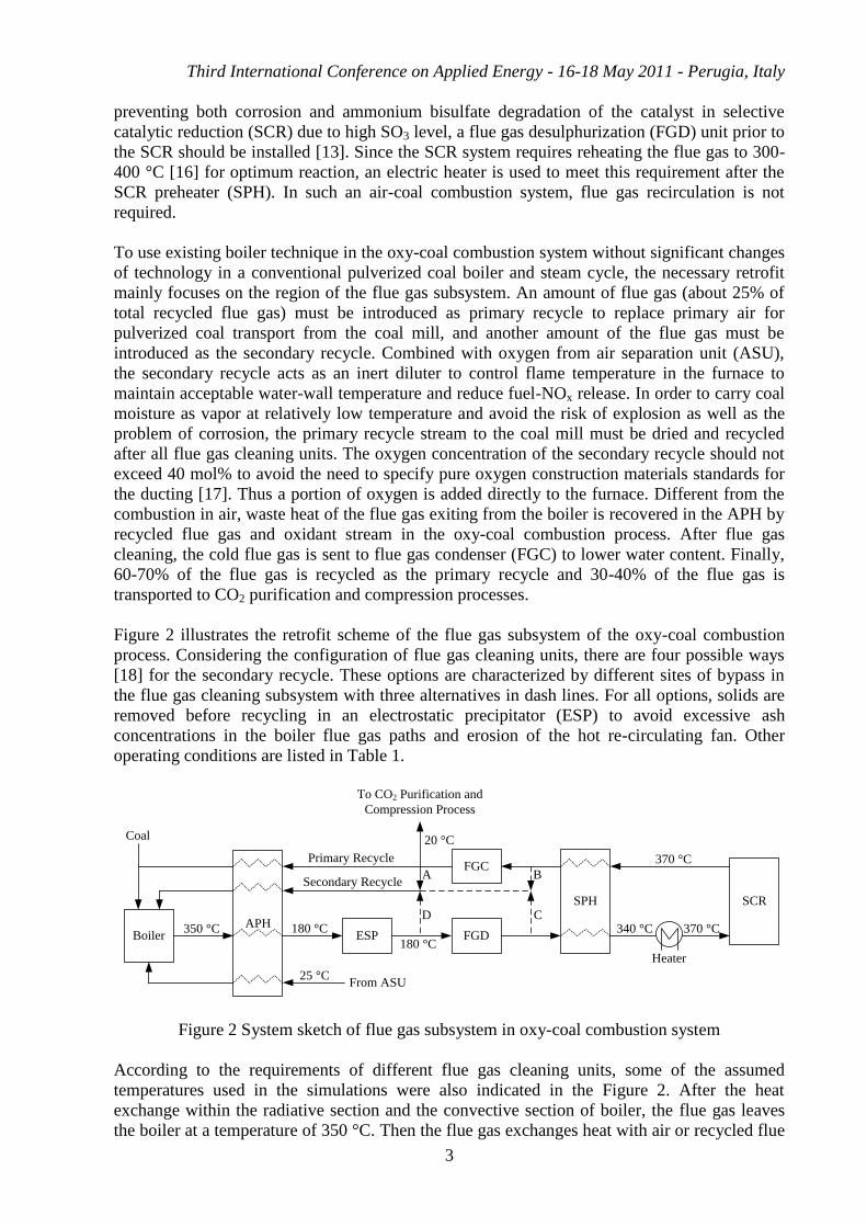
3. System description
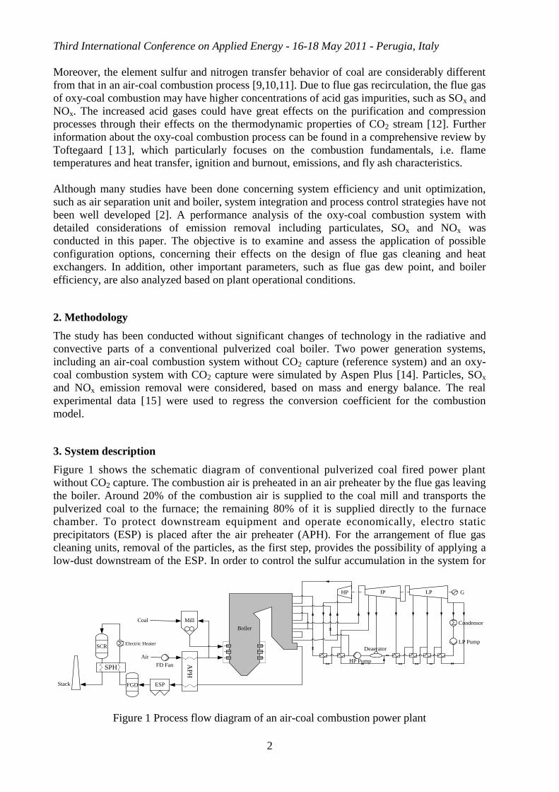
Figure 1 shows the schematic diagram of conventional pulverized coal fired power plant
without CO2 capture. The combustion air is preheated in an air preheater by the flue gas leaving
the boiler. Around 20% of the combustion air is supplied to the coal mill and transports the
pulverized coal to the furnace; the remaining 80% of it is supplied directly to the furnace
chamber. To protect downstream equipment and operate economically, electro static
precipitators (ESP) is placed after the air preheater (APH). For the arrangement of flue gas
cleaning units, removal of the particles, as the first step, provides the possibility of applying a
low-dust downstream of the ESP. In order to control the sulfur accumulation in the system for
ESPFGD
MillCoal
Air
Deaerator
HP G
Boiler
FD Fan
Condensor
LP Pump
HP PumpAP
H
Electric HeaterSCR
SPH
Stack
IP LP
Figure 1 Process flow diagram of an air-coal combustion power plant
Third International Conference on Applied Energy - 16-18 May 2011 - Perugia, Italy
3
preventing both corrosion and ammonium bisulfate degradation of the catalyst in selective
catalytic reduction (SCR) due to high SO3 level, a flue gas desulphurization (FGD) unit prior to
the SCR should be installed [13]. Since the SCR system requires reheating the flue gas to 300-
400 °C [16] for optimum reaction, an electric heater is used to meet this requirement after the
SCR preheater (SPH). In such an air-coal combustion system, flue gas recirculation is not
required.
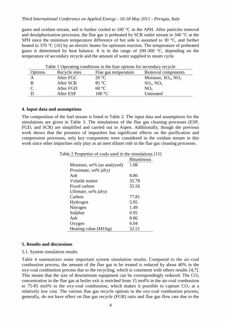
To use existing boiler technique in the oxy-coal combustion system without significant changes
of technology in a conventional pulverized coal boiler and steam cycle, the necessary retrofit
mainly focuses on the region of the flue gas subsystem. An amount of flue gas (about 25% of
total recycled flue gas) must be introduced as primary recycle to replace primary air for
pulverized coal transport from the coal mill, and another amount of the flue gas must be
introduced as the secondary recycle. Combined with oxygen from air separation unit (ASU),
the secondary recycle acts as an inert diluter to control flame temperature in the furnace to
maintain acceptable water-wall temperature and reduce fuel-NOx release. In order to carry coal
moisture as vapor at relatively low temperature and avoid the risk of explosion as well as the
problem of corrosion, the primary recycle stream to the coal mill must be dried and recycled
after all flue gas cleaning units. The oxygen concentration of the secondary recycle should not
exceed 40 mol% to avoid the need to specify pure oxygen construction materials standards for
the ducting [17]. Thus a portion of oxygen is added directly to the furnace. Different from the
combustion in air, waste heat of the flue gas exiting from the boiler is recovered in the APH by
recycled flue gas and oxidant stream in the oxy-coal combustion process. After flue gas
cleaning, the cold flue gas is sent to flue gas condenser (FGC) to lower water content. Finally,
60-70% of the flue gas is recycled as the primary recycle and 30-40% of the flue gas is
transported to CO2 purification and compression processes.
Figure 2 illustrates the retrofit scheme of the flue gas subsystem of the oxy-coal combustion
process. Considering the configuration of flue gas cleaning units, there are four possible ways
[18] for the secondary recycle. These options are characterized by different sites of bypass in
the flue gas cleaning subsystem with three alternatives in dash lines. For all options, solids are
removed before recycling in an electrostatic precipitator (ESP) to avoid excessive ash
concentrations in the boiler flue gas paths and erosion of the hot re-circulating fan. Other
operating conditions are listed in Table 1.
BoilerAPH
ESP FGD
SPH SCR
350 °C
Heater
370 °C
370 °C
340 °C
FGCPrimary Recycle
Secondary Recycle
From ASU
To CO2 Purification and
Compression Process
20 °C
25 °C
A B
CD180 °C
180 °C
Coal
Figure 2 System sketch of flue gas subsystem in oxy-coal combustion system
According to the requirements of different flue gas cleaning units, some of the assumed
temperatures used in the simulations were also indicated in the Figure 2. After the heat
exchange within the radiative section and the convective section of boiler, the flue gas leaves
the boiler at a temperature of 350 °C. Then the flue gas exchanges heat with air or recycled flue
Third International Conference on Applied Energy - 16-18 May 2011 - Perugia, Italy
4
gases and oxidant stream, and is further cooled to 180 °C in the APH. After particles removal
and desulphurization processes, the flue gas is preheated by SCR outlet stream to 340 °C at the
SPH since the minimum temperature difference of hot side is assumed to 30 °C, and further
heated to 370 °C [16] by an electric heater for optimum reaction. The temperature of preheated
gases is determined by heat balance. It is in the range of 200-300 °C, depending on the
temperature of secondary recycle and the amount of water supplied to steam cycle.
Table 1 Operating conditions in the four options for secondary recycle
Options Recycle sites Flue gas temperature Removal components
A After FGC 20 °C Moisture, SOx, NOx
B After SCR 85 °C SOx, NOx
C After FGD 60 °C NOx
D After ESP 180 °C Untreated
4. Input data and assumptions
The composition of the fuel stream is listed in Table 2. The input data and assumptions for the
simulations are given in Table 3. The simulations of the flue gas cleaning processes (ESP,
FGD, and SCR) are simplified and carried out in Aspen. Additionally, though the previous
work shows that the presence of impurities has significant effects on the purification and
compression processes, only key components were considered in the oxidant stream in this
work since other impurities only play as an inert diluter role in the flue gas cleaning processes.
Table 2 Properties of coals used in the simulations [15]
Bituminous
Moisture, wt% (as analyzed) 1.08
Proximate, wt% (dry)
Ash 8.86
Volatile matter 35.78
Fixed carbon 55.56
Ultimate, wt% (dry)
Carbon 77.81
Hydrogen 5.05
Nitrogen 1.49
Sulphur 0.95
Ash 8.86
Oxygen 6.04
Heating value (MJ/kg) 32.51
5. Results and discussions
5.1. System simulation results
Table 4 summarizes some important system simulation results. Compared to the air -coal
combustion process, the amount of the flue gas to be treated is reduced by about 40% in the
oxy-coal combustion process due to the recycling, which is consistent with others results [4,7].
This means that the size of downstream equipment can be correspondingly reduced. The CO2
concentration in the flue gas at boiler exit is enriched from 15 mol% in the air-coal combustion
to 75-85 mol% in the oxy-coal combustion, which makes it possible to capture CO2 at a
relatively low cost. The various flue gas recycle options in the oxy-coal combustion process,
generally, do not have effect on flue gas recycle (FGR) ratio and flue gas flow rate due to the

Third International Conference on Applied Energy - 16-18 May 2011 - Perugia, Italy
5
same combustion parameters, such as oxygen concentration and excess oxygen etc. However,
the flue gas composition at the exit of boiler is changed with them, particularly H2O and SO2
which play decisive roles for flue gas dew point [19]. Since flue gas is recycled before FGD
and SCR, Option D results in the highest concentrations of NO and SO2. For the same reason,
Table 3 Input data and assumptions for the simulations
Unit Value
Fuel input kg/sec 30.76
Oxidant stream
T °C 15
P bar 1
Air composition
N2 mol% 79
O2 mol% 21
Oxygen composition
Ar mol% 1
O2 mol% 99
Energy consumption MJ/kgO2 0.9 [20]
Intercooling temperature of air compression °C 10
Boiler
Excess O2 mol% 2.1
O2 content of oxidant mol% 35
Steam cycle
Turbine isentropic efficiency % 87
Pump efficiency % 75
Steam temperature* °C 540/540
Steam pressure** bar 190/0.06
1st extracted steam of IP bar/°C 20/473
2nd
extracted steam of IP bar/°C 10.5/386
3rd
extracted steam of IP bar/°C 5.2/302
1st extracted steam of LP bar/°C 2.2/210
2nd
extracted steam of LP bar/°C 0.7/110
3rd
extracted steam of IP bar/°C 0.3/70
Flue gas cleaning process
ESP removal efficiency % 99
FGD removal efficiency % 99
SCR removal efficiency % 95
Other assumptions
ΔTmin gas/gas °C 30
ΔTmin gas/liquid °C 20
Gas/Gas heat transfer coefficient W/m2°C 30
*Temperature of superheated steam/ temperature of reheated steam
**Inlet pressure/back pressure
Third International Conference on Applied Energy - 16-18 May 2011 - Perugia, Italy
6
Options C results in a much higher concentration of NO than Options A and B, and Option A
results in the lowest water content. Even though the concentrations of NO and SO2 are higher
in oxy-coal combustion system than those in air-coal combustion system, the emitted amounts
(mol) of NO and SO2 are lower in oxy-coal combustion systems due to the largely reduced
flow rate of flue gas. This means that the oxy-coal combustion has a lower NO and SO2
formation rate compared to the air-coal combustion under the combustion conditions (oxygen
concentration = 35 mol%; excess oxygen = 2 mol%). After flue gas cleaning processes, all
recycle options can reach around 96 mol% (dry basis) of CO2%, and such high CO2% flue gas
stream can be captured and compressed without further separation.
Table 4 Summary of system simulation results
Air-coal Oxy-coal
Option A Option B Option C Option D
FGR ratio*, % N/A 61.7 61.6 61.6 61.6
Exit of boiler
Flow rate, kmol/hr 45463 26646 26645 26642 26641
Composition, mol%
CO2 15.6 84.4 75.7 75.0 78.9
H2O 6.2 11.9 21.1 21.1 17.6
NO (ppm) 548 705 624 918 1002
SO2 (ppm) 576 735 736 735 1367
After flue gas cleaning
processes
Flow rate, kmol/hr 49326 7467 7489 7489 7503
Composition, mol%
CO2 14.3 93.8 93.6 93.6 93.7
H2O 13.5 2.2 2.2 2.2 2.2
NO (ppm) 25 39 39 57 60
SO2 (ppm) 5 8 8 8 15
Flue gas dew points, °C 114 122 129 129 131
Boiler efficiency, % 85.5 94.6 95.3 95.0 96.0
Gross el. efficiency, % 41.0 41.7 42.1 41.9 42.4
*
5.2. Design of flue gas cleaning
5.2.1. Heat exchangers
There are two main heat exchangers in the process of each system to recovery the waste heat of
the flue gas. One is in the air preheater (APH), which is located at the exit of the economizer. It
is used to preheat the air supplied in combustion in the air-coal combustion, and the oxygen
stream and recycled flue gases in the oxy-coal combustion. The various recycle options result
in the recycled flue gases with different temperatures, therefore the heat exchange area of the
air preheater is changed correspondingly. Another one is in the SCR preheater (SPH), which is
located at the exit of SCR. It is used to preheat the flue gas treated in the SCR in both the air-
coal and oxy-coal combustion with different flow rate due to various recycle options. The heat
duties of heat exchangers are listed in Table 5. Compared to the air-coal combustion system,
the heat duties are decreased by about 20% and 30-55% for the APH and the SPH respectively
in the oxy-coal combustion system due to the reduced flow rate of fuel gas. Various options
don’t vary the heat duty of APH clearly. However, Options A and B result in a much higher
heat duty in the APH than Options C and D.
Third International Conference on Applied Energy - 16-18 May 2011 - Perugia, Italy
7
Table 5 Summary of heat integration sources (MW) Air-coal Oxy-coal
Hot source Cold source Option A Option B Option C Option D
APH Flue gas at
exit of boiler
Oxidant stream 70.62 14.97 17.24 16.23 18.74
Primary recycle N/A 16.48 18.80 17.65 20.37
Secondary recycle N/A 24.17 18.40 20.61 15.81
Total 70.62 55.62 54.44 54.49 54.92
SPH Flue gas at
SCR outlet
Flue gas at exit of
FGD
127.33 94.34 89.64 59.13 56.99
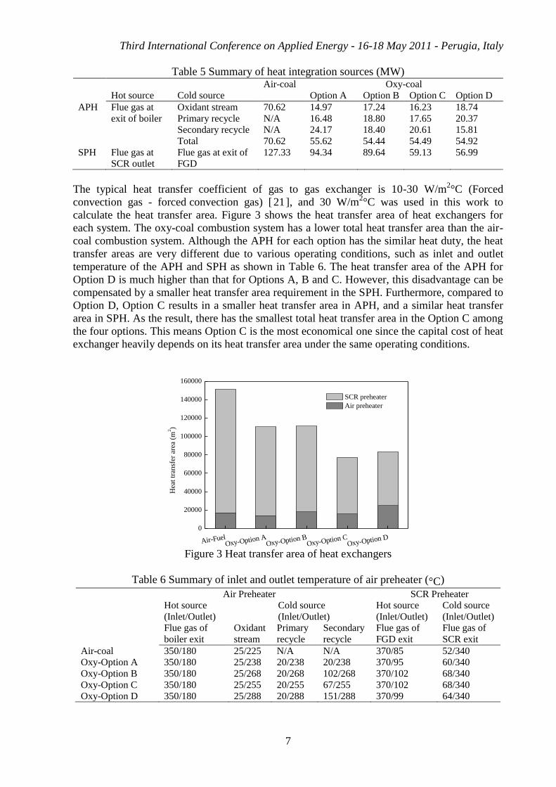
The typical heat transfer coefficient of gas to gas exchanger is 10-30 W/m2°C (Forced
convection gas - forced convection gas) [21], and 30 W/m2°C was used in this work to
calculate the heat transfer area. Figure 3 shows the heat transfer area of heat exchangers for
each system. The oxy-coal combustion system has a lower total heat transfer area than the air-
coal combustion system. Although the APH for each option has the similar heat duty, the heat
transfer areas are very different due to various operating conditions, such as inlet and outlet
temperature of the APH and SPH as shown in Table 6. The heat transfer area of the APH for
Option D is much higher than that for Options A, B and C. However, this disadvantage can be
compensated by a smaller heat transfer area requirement in the SPH. Furthermore, compared to
Option D, Option C results in a smaller heat transfer area in APH, and a similar heat transfer
area in SPH. As the result, there has the smallest total heat transfer area in the Option C among
the four options. This means Option C is the most economical one since the capital cost of heat
exchanger heavily depends on its heat transfer area under the same operating conditions.
Air-FuelOxy-Option A
Oxy-Option BOxy-Option C
Oxy-Option D
0
20000
40000
60000
80000
100000
120000
140000
160000
Hea
t tr
ansf
er a
rea
(m2)
SCR preheater
Air preheater
Figure 3 Heat transfer area of heat exchangers
Table 6 Summary of inlet and outlet temperature of air preheater (°C)
Air Preheater SCR Preheater
Hot source
(Inlet/Outlet) Cold source
(Inlet/Outlet) Hot source
(Inlet/Outlet) Cold source
(Inlet/Outlet)
Flue gas of
boiler exit
Oxidant
stream
Primary
recycle
Secondary
recycle
Flue gas of
FGD exit
Flue gas of
SCR exit
Air-coal 350/180 25/225 N/A N/A 370/85 52/340
Oxy-Option A 350/180 25/238 20/238 20/238 370/95 60/340
Oxy-Option B 350/180 25/268 20/268 102/268 370/102 68/340
Oxy-Option C 350/180 25/255 20/255 67/255 370/102 68/340 Oxy-Option D 350/180 25/288 20/288 151/288 370/99 64/340

Third International Conference on Applied Energy - 16-18 May 2011 - Perugia, Italy
8
5.2.2. Considerations on cold end corrosion
The condensation of acidic aqueous species on the heat exchanger surfaces may cause serious
corrosion problems, for this reason, the air preheater needs very careful design. Several factors
can affect the oxidation of SO2, including the combustion mode, catalytic oxidation of SO2
with the oxides of vanadium and iron, the fly ash etc. However, they cannot be implemented in
the simulation. Empirical methods are often used in engineering practice to calculate the dew
point temperature of H2SO4. The method proposed by Okkes (1987) is used in this work, which
has the expression [22]:
( )
(1)
It assumes that 1.0% of the SO2 converts to SO3 during combusting. Table 7 lists the results of
flue gas dew point estimation. The dew point of flue gas in the oxy-coal combustion is always
higher than that in the air-coal combustion for all options mainly due to the higher moisture
content in raw flue gas. Option D results in the highest dew point temperature. The largely
difference appears compared Option D to air-coal combustion, which is 17 °C. The largest
difference amongst those four options in oxy-coal combustion is 9 °C, compared Option A to
Option D. Basically, there are two approaches to deal with the problem of cold end corrosion.
Corrosion can be avoided by maintaining a high cold end temperature above flue gas dew point
or using corrosion resistant materials, such as polypropylene and glass reinforced plastics.
Former approach will reduce the overall efficiency by 1-2% points; while the latter approach,
taking polypropylene costing as example, will increase about 5% of the total capital cost [23].
Table 7 Flue gas dew point estimation
Air-coal Oxy-coal
Option A Option B Option C Option D
PH2O, bar 0.062 0.119 0.211 0.211 0.176
PSO3, μbar 5.76 7.35 7.36 7.35 13.67
TDP, °C 114 122 129 129 131
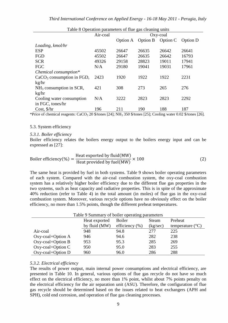
5.2.3. Operation of flue gas cleaning processes
Since the volume of the flue gas was reduced largely due to the flue gas recycle, the
downstream equipment will benefit from the reduced flow amount in equipment sizes or
loadings. Table 8 lists the results of operation parameters of flue gas cleaning units for each
system. In general the loadings of flue gas cleaning units in the air-coal combustion system are
much higher than the oxy-coal combustion system, particularly for the system with more prior
upstream recycle options.
For the oxy-coal combustion system, Option D results in the smallest loading in FGD, SCR and
FGC among all options. Additionally, the chemical consumption is proportional to the amount
(mol) of impurity. With consideration of different flue gas compositions (Table 4), therefore,
Option D causes the highest CaCO3 consumption in the FGD and Option A causes the highest
NH3 consumption in the SCR. Furthermore, Option A causes the highest cooling water
consumption in the FGC due to all flue gas condensed before the recycling. However, chemical
reagents have much different prices, as the results, Options B, C, D result in the similar total
chemical costs, and Option A is the most costly option.
Third International Conference on Applied Energy - 16-18 May 2011 - Perugia, Italy
9
Table 8 Operation parameters of flue gas cleaning units
Air-coal Oxy-coal
Option A Option B Option C Option D
Loading, kmol/hr
ESP 45502 26647 26635 26642 26641
FGD 45502 26647 26635 26642 16793
SCR 49326 29158 28823 19011 17941
FGC N/A 29180 19041 19031 17961
Chemical consumption*
CaCO3 consumption in FGD,
kg/hr
2423 1920 1922 1922 2231
NH3 consumption in SCR,
kg/hr
421 308 273 265 276
Cooling water consumption
in FGC, tones/hr
N/A 3222 2823 2823 2292
Cost, $/hr 196 211 190 188 187 *Price of chemical reagents: CaCO3 20 $/tones [24]; NH3 350 $/tones [25]; Cooling water 0.02 $/tones [26].
5.3. System efficiency
5.3.1. Boiler efficiency
Boiler efficiency relates the boilers energy output to the boilers energy input and can be
expressed as [27]:
( ) ( )
( ) ( )
The same heat is provided by fuel in both systems. Table 9 shows boiler operating parameters
of each system. Compared with the air-coal combustion system, the oxy-coal combustion
system has a relatively higher boiler efficiency due to the different flue gas properties in the
two systems, such as heat capacity and radiative properties. This is in spite of the approximate
40% reduction (refer to Table 4) in the total amount (in moles) of flue gas in the oxy-coal
combustion system. Moreover, various recycle options have no obviously effect on the boiler
efficiency, no more than 1.5% points, though the different preheat temperatures.
Table 9 Summary of boiler operating parameters
Heat exported
by fluid (MW)
Boiler
efficiency (%)
Steam
(kg/sec)
Preheat
temperature (°C)
Air-coal 948 94.8 277 225
Oxy-coal+Option A 946 94.6 282 238
Oxy-coal+Option B 953 95.3 285 269
Oxy-coal+Option C 950 95.0 283 255
Oxy-coal+Option D 960 96.0 286 288
5.3.2. Electrical efficiency
The results of power output, main internal power consumptions and electrical efficiency, are
presented in Table 10. In general, various options of flue gas recycle do not have so much
effect on the electrical efficiency, no more than 1% point, whilst about 7% points penalty on
the electrical efficiency for the air separation unit (ASU). Therefore, the configuration of flue
gas recycle should be determined based on the issues related to heat exchangers (APH and
SPH), cold end corrosion, and operation of flue gas cleaning processes.
Third International Conference on Applied Energy - 16-18 May 2011 - Perugia, Italy
10
Table 10 Main results of simulations
Air-coal Oxy-coal
Unit Option A Option B Option C Option D
Flue gas dew point °C 114 122 129 129 131
Chemical cost $/hour 196 211 190 188 187
Boiler efficacy % 94.8 94.6 95.3 95.0 96.0
ASU plant MW N/A 68 68 68 68
SCR heater MW 13.9 11.0 10.6 7.0 6.7
Gross power output MW 410 417 421 419 424
Gross el. efficiency %LHV 41.0 41.7 42.1 41.9 42.4
6. Conclusions
This paper examined and assessed various configurations of emissions removal in the oxy-coal
combustion system. The following conclusions can be drawn:
(1) Compared to the air-coal combustion, much lower amount of the flue gas (about 40%
reduction) needs to be treated in the oxy-coal combustion, resulting in lower emitted flow rates
of NO and SO2. Various flue gas recycle options have no effects on flue gas recycle (FGR)
ratio and flue gas flow rate, but they have clear effects on the flue gas composition at the exit of
boiler.
(2) Various recycle configurations in the oxy-coal systems require different heat exchanger
areas in air preheater and SCR preheater. The difference can be up to 40% in the total heat
transfer area.
(3) The dew point of flue gas in the oxy-coal combustion is higher than that in the air-coal
combustion for all options mainly due to the higher moisture content in raw flue gas. Recycling
flue gas after or before FGC result in the lowest or the highest dew point, respectively.
(4) Loadings of flue gas cleaning units and chemical consumptions for various recycle options
are quite different due to their effects on the flow rate and impurity content.
(5) Boiler efficiency in the oxy-coal combustion system is relatively higher than that in the air-
coal combustion system. Various recycle options result in quite similar electrical efficiency,
and the differences are no more than 1% point.
7. Acknowledgments
One of the authors, Yukun Hu, appreciates the financial support by China Scholarship Council
(CSC) and Royal Institute of Technology (KTH), Sweden.
Abbreviations
APH Air preheater
ASU Air separation unit
CCS CO2 capture and storage
DP Dew point
ESP Electro static precipitators
FGC Flue gas condenser
FGD Flue gas desulphurization
Third International Conference on Applied Energy - 16-18 May 2011 - Perugia, Italy
11
FGR Flue gas recycle
HP High pressure
IP Intermediate pressure
LHV Lower heating value
LP Low pressure
N/A No applicable
SCR Selective catalytic reduction
SPH SCR preheater
References
[1] EIA, 2009, “EIA Annual Energy Outlook 2009 with Projections to 2030”.
[2] IPCC, 2005, “IPCC Special Report on Carbon Dioxide Capture and Storage”. Cambridge
University Press, Cambridge, United Kingdom and New York, NY, USA, 442 pp
[3] Wall T.F., 2007, “Combustion processes for carbon capture”, Proceedings of the
Combustion Institute, Vol 31, pp. 31-47.
[4] Chen J., Liu Z., Huang J., 2007, “Emission characteristics of coal combustion in different
O2/N2, O2/CO2 and O2/RFG atmosphere”, Journal of Hazardous Materials, Vol 142, pp. 266-
271.
[5] Kim H.K., Kim Y., Lee S.M., Ahn K.Y., 2007, “NO reduction in 0.03-0.2 MW oxy-fuel
combustor using flue gas recirculation technology”, Proceedings of the combustion institute,
Vol 31, pp. 3377-3384.
[6] Buhre B.J.P., Elliott L.K., Sheng C.D., Gupta R.P., Wall T.F., 2005, “Oxy-fuel combustion
technology for coal-fired power generation”, Progress in Energy and Combustion Science, Vol
31, pp. 283-307.
[7] Wall T.F., Liu Y., Spero C., Elliott L., Khare S., Rathnam R., Zeenathal F., Moghtaderi B.,
Buhre B., Sheng C., Gupta R., Yamada T., Makino K., Yu J., 2009, “An overview on oxyfuel
coal combustion—State of the art research and technology development”, Chemical
Engineering Research and Design, Vol 87, pp. 1003-16.
[8] Kakaras E., Koumanakos A., Doukelis A., Goukelis D., Giannakopoulos D., Vorrias I.,
2007, “Oxyfuel boiler design in a lignite-fired power plant”, Fuel, Vol 86, pp. 2144-55.
[9] Hu Y., Naito S., Kobayashi N., Hasatani M., 2000, “CO2, NOx and SO3 emissions from the
combustion of coal with high oxygen concentration gases”, Fuel, Vol 79, pp. 1925-1932.
[10] Normann F., Andersson K., Leckner B., Johnsson F., 2009, “Emission control of nitrogen
oxides in the oxy-fuel process”, Progress in Energy and Combustion Science, Vol 35, pp. 385-
397.
[11] Liu H., Shao Y., 2010, “Predictions of the impurities in the CO2 stream of an oxy-coal
combustion plant”, Applied Energy, Vol 87, pp. 3162-70.
Third International Conference on Applied Energy - 16-18 May 2011 - Perugia, Italy
12
[12] Li H., Yan J., Yan J., Anheden M., 2009, “Impurity impacts on the purification process in
oxy-fuel combustion based CO2 capture and storage system”, Applied Energy, Vol 86, pp. 202-
13.
[ 13 ] Toftegaard M.B., Brix J., Jensen P.A., Glarborg P., Jensen A.D., 2010, “Oxy-fuel
combustion of solid fuels”, Progress in Energy and Combustion Science, Vol 36, pp. 581-625.
[14] Aspen Plus, 2007, “Aspen Plus User Guide”, Aspen Technology, Massachusetts, 2007.
[15] Tan Y., Croiset E., Douglas M.A., Thambimuthu K.V., 2006, “Combustion characteristics
of coal in a mixture of oxygen and recycled flue gas”, Fuel, Vol 85, pp. 507-12.
[16] Nalbandian H., 2004, “Air pollution control technologies and their interactions”. CCC/92,
IEA Clean Coal Centre, ISBN 92-9029-407-8, 75 pp, November 2004.
[17] IEA Greenhouse Gas R&D Programme: Oxy-Combustion Processes for CO2 Capture from
Power Plant, Report No: E/04/031.
[18] Hu Y., Yan J., “Characterization of flue gas in oxy-coal combustion processes for CO2
capture”, Applied Energy, In Press.
[19] Ganapathy V., 1989, “Cold end corrosion: causes and cures”, Hydrocarbon Processing, pp.
57-59.
[20] Bolland O., Mathieu P., 1998, “Comparison of two CO2 removal options in combined
cycle power plants”, Energy Conversion and Management, Vol 39, pp. 1653-63.
[21] Overall Heat Transfer Coefficient, Calculate overall heat transfer coefficient - walls or
heat exchangers,
http://www.engineeringtoolbox.com/overall-heat-transfer-coefficient-d_434.html, access date:
February 3, 2011.
[ 22 ] Okkes A.G., Badger B.V., 1987, “Get acid dew point of flue gas”, Hydrocarbon
Processing pp. 53-55.
[23] Guidetti G.P., Rigosi G.L., Marzola R., 1996, “The use of polypropylene in pipeline
coatings”, Progress in organic coatings, Vol 27, pp. 79-85.
[24] Gansley R., 2008, “Wet FGD system overview and operation”, WPCA wet FGD seminar,
Orlando, December 1, 2008.
[25] Wu S., Fan Z., Seltzer A.H., 2005, “Ammonia-free NOx control system”. Quarterly
technical progress report, NO. 41865R8, Foster Wheeler North America Corp., Issued: October
31, 2005.
[26] Turton R., Bailie R.C., Whiting W.B., Shaeiwitz J.A., 2003, “Analysis, synthesis, and
design of chemical processes (2nd
Edition)”. Prentice Hall PTR, 2003.
[27] Basu P., Cen K., Jestin L., 2000, “Boilers and Burners”. Springer & Verlag, New York,
2000.