Embed Size (px)
Citation preview
HAL Id: hal-01569451https://hal.archives-ouvertes.fr/hal-01569451
Submitted on 26 Jul 2017
HAL is a multi-disciplinary open accessarchive for the deposit and dissemination of sci-entific research documents, whether they are pub-lished or not. The documents may come fromteaching and research institutions in France orabroad, or from public or private research centers.
L’archive ouverte pluridisciplinaire HAL, estdestinée au dépôt et à la diffusion de documentsscientifiques de niveau recherche, publiés ou non,émanant des établissements d’enseignement et derecherche français ou étrangers, des laboratoirespublics ou privés.
Effects of Ageing on the Bond Properties of CarbonFiber Reinforced Polymer/Concrete Adhesive Joints:
Investigation Using a Modified Double Shear TestMarc Quiertant, Karim Benzarti, Julien Schneider, Fabrice Landrin, Mathieu
Landrin, Frédéric Boinski
To cite this version:Marc Quiertant, Karim Benzarti, Julien Schneider, Fabrice Landrin, Mathieu Landrin, et al.. Effectsof Ageing on the Bond Properties of Carbon Fiber Reinforced Polymer/Concrete Adhesive Joints:Investigation Using a Modified Double Shear Test. Journal of Testing and Evaluation, ASTM Inter-national, 2017, 45 (6), �10.1520/JTE20160587�. �hal-01569451�
For Review O
nly
Effect of ageing on the bond properties of CFRP/Concrete
adhesive joints: investigation using a modified double shear test
Journal: Journal of Testing and Evaluation
Manuscript ID JTE-2016-0587.R1
Manuscript Type: Technical Manuscript
Date Submitted by the Author: n/a
Complete List of Authors: Quiertant, Marc; IFSTTAR, Benzarti, Karim; IFSTTAR Schneider, Julien; cerema direction territoriale Ile-de-France Landrin, Fabrice; cerema direction territoriale Ile-de-France Landrin, Mathieu; cerema direction territoriale Ile-de-France Boinski, Frédéric; cerema direction territoriale Ile-de-France
ASTM Committees and Subcommittees:
D04.20 Mechanical Tests of Bituminous Mixtures < D04 ommittee on Road and Paving Materials
Keywords: CFRP, hydrothermal ageing, epoxy, shear test
https://mc04.manuscriptcentral.com/astm-jote
Journal of Testing and Evaluation
For Review O
nly
Effects of ageing on the bond properties of carbon fiber reinforced
polymer /concrete adhesive joints: investigation using a modified
double shear test
Marc Quiertant, Karim Benzarti
Université Paris-Est, IFSTTAR, Département Matériaux et Structures, France
[email protected] (Corresponding author)
Julien Schneider, Fabrice Landrin, Mathieu Landrin, Frédéric Boinski
CEREMA - DT Id/LEM/UCMA, France
Abstract Although externally bonded carbon Fiber Reinforced Polymer (FRP) composites are now commonly
used for the strengthening and repair of reinforced concrete structures, the durability of the adhesive bond at the
concrete/composite interface is still a matter of investigation and remains a critical issue to be addressed in order
to assess the long-term performance of FRP strengthening methods. The proposed paper aims at presenting the
results of an investigation on the time evolution of the adhesive bond strength of concrete/composite assemblies
exposed to accelerated ageing. Such an evolution was studied by performing double lap shear tests at several
intermediate periods of ageing up to 1 year, while changes in the mechanical properties of the weakest
constitutive materials, namely polymer adhesive and concrete, were investigated by means of tensile and
compressive tests respectively. Considering that an increase in the transfer length of aged samples can
counterbalance the ageing-induced degradation of the mechanical properties of the bulk adhesive and can finally
lead to an unchanged shear capacity of the joint, a new geometry of double-shear test specimens is proposed.
This geometry involves a smaller bonded length and consequently restricts the possible increase in transfer
length during ageing. Moreover, their reduced size allows the storage of a large number of samples in standard
climatic chambers. A specific anchorage device was designed, so that double lap shear tests could be carried out
Page 1 of 28
https://mc04.manuscriptcentral.com/astm-jote
Journal of Testing and Evaluation
123456789101112131415161718192021222324252627282930313233343536373839404142434445464748495051525354555657585960
For Review O
nly
2
using a conventional universal testing machine. The obtained results show that the shear tests based on this
original setup are able to reveal the evolutions of both the bond strength and the failure mode of
concrete/composite assemblies subjected to various accelerated ageing conditions. Ageing conditions were found
to have only slight detrimental effects on the mechanical characteristics of samples, and finally a partial recovery
was observed.
Keywords CFRP, epoxy, hydrothermal ageing, shear test.
1 Introduction
The effectiveness of field externally bonded Fiber Reinforced Polymers (FRPs) for the strengthening and repair
of Reinforced Concrete (RC) structures has been widely demonstrated and is now worldwide accepted [1-5].
However, the durability of the adhesive bond at the concrete/FRP interface is still a matter of investigation and
remains a critical issue to be addressed in order to assess the long-term performance of FRP strengthening
methods [6-11].
The purpose of this paper is to present the results of a 12-month experimental investigation on the
environmental durability of the concrete/carbon FRP (CFRP) adhesive bond conducted (preliminary results were
also reported in [12]. Since some detrimental effects of moisture on the mechanical properties of FRP/concrete
assemblies have been reported, especially with the use of cold-curing epoxy adhesives [11, 13, 14], and since the
rate of moisture diffusion increases with temperature, hygrothermal ageing conditions are considered in the
present study. Moreover, as underlined by Yun and Wu [15], the durability of FRP/concrete joints under freeze-
thaw cycling has received insufficient attention, and contradictory results were reported by different authors. On
the one hand, a decrease in residual strength as a function of the number of cycles was observed by many authors
[16-18], which is consistent with the fact that constituents of the joint (FRP, adhesive and concrete) exhibit
different thermal expansion behaviors. On the other hand, several studies [19-23] reported a preservation, and
sometimes an increase in bond strength after freeze-thaw cycling. Thus, freeze-thaw conditions are also
considered in the present durability study. The evolution of the mechanical properties of the bulk adhesive and
concrete are investigated through tensile and compressive tests respectively, and the time evolution of the
adhesive bond strength is studied through characterization with double lap shear tests.
Page 2 of 28
https://mc04.manuscriptcentral.com/astm-jote
Journal of Testing and Evaluation
123456789101112131415161718192021222324252627282930313233343536373839404142434445464748495051525354555657585960
For Review O
nly
3
Many different experimental set-ups, loading conditions and sample geometries have been used to study the
shear behavior of FRP-strengthened concrete samples (see for example the classification proposed in [24]). The
principles of such shear tests are presented further in the paper. However, in most cases, the concrete prisms used
are long enough to bond the FRP reinforcement with a bonded length greater than the effective anchorage length.
Besides, previous studies [9, 25] have reported that an increase in the transfer length of aged samples can
counterbalance the ageing-induced degradation of the mechanical properties of the polymer adhesive. In this
case, the shear capacity of the joint remains globally unchanged, which makes the shear test potentially
inefficient to detect the degradation of the adhesive joint properties (except for a possible change in the failure
mode as reported in [9]). To overcome this difficulty, a new geometry of double-shear test specimens is
proposed in this work, with a small bonded length that limits the possible increase in transfer length during
ageing. Moreover, the reduced size of the double shear specimens allows storing a large number of samples in
standard climatic chambers. A specific fixture device was also designed for the specimens, so that the double lap
shear tests can be performed using a conventional universal testing machine.
Finally, the observed time evolutions of the shear capacities of CFRP/concrete assemblies (strength and
failure mode) subjected to the various abovementioned environments (hygrothermal ageing at 40°C under
constant relative humidity or hygric cycles, freeze thaw cycles) are presented and discussed in view of the
changes in mechanical properties of the constitutive materials (bulk adhesive and concrete).
2 Experimental program
To investigate the effects of accelerated ageing on the adhesive bond between concrete substrate and externally
bonded Carbon FRP (CFRP) plates, specific shear test specimens were first designed. Then 84 of such
specimens were constructed, exposed to various environments and finally tested. Double shear test experiments
were periodically carried out over a period of 1 year, to monitor the bond strength of aged specimens. The
evolutions of the concrete compressive strength and the tensile strength of the bulk polymer adhesive were also
monitored over time. The durability of the pultruded CFRP plate was not investigated here, as this material is
supposed to be not significantly affected by environmental ageing conditions [10].
Page 3 of 28
https://mc04.manuscriptcentral.com/astm-jote
Journal of Testing and Evaluation
123456789101112131415161718192021222324252627282930313233343536373839404142434445464748495051525354555657585960
For Review O
nly
4
2.1 Double shear test experiments
2.1.1 Principle of the double-shear test
In FRP strengthened RC beams, the load between FRP plate and concrete substrate is primarily transferred
through interfacial shear stresses. Then, simplified shear tests are usually considered suitable to assess the bond
strength of concrete–FRP interfaces [26]. In the experimental program described in this paper, double shear test
experiments were carried out. Test specimens are composed of two concrete blocks attached by two parallel
bonded FRP plates (Fig. 1.a). A load applied (F) to the concrete blocks produces a shear stress along the
adhesive joint (Fig. 1.b). Each lap joint is then submitted to the average shear stress (τave), which can be
calculated according to:
adh
aveA
F
2=τ (MPa) (1)
where Aadh is the bonded area of each lap joint [27].
It will be discussed later in this paper that the concrete prisms used in the present study are smaller than those
commonly used for double lap shear tests (see for example the standard test proposed by the Japanese Concrete
Institute in [28]). Since a realistic concrete mixture was adopted, based on a maximum gravel size of 20mm, it
was not possible to embed a steel rod in the concrete without weakening the prisms. Such embedded steel rods
are usually used to transmit the load from the universal testing machine to the concrete prisms, but preliminary
tests showed that this type of fixture led to the systematic failure of the concrete prisms in our case, as illustrated
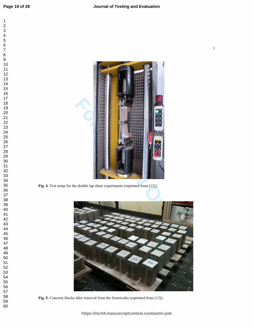
in Fig. 2. Consequently, alternative fixture devices were designed. One of the two devices is shown in Fig. 3,
whereas the overall shear test setup is presented in Fig. 4.
2.1.2 Double-shear test specimens
As reported by Aydin, Gravina, and Visintin [29], and previously underlined in the introduction section, several
researchers have observed changes in the effective transfer length of FRP after ageing. Moreover, in Benzarti et
al. [9] it was also noticed that, in the condition of the study, this phenomenon was accompanied by a roughly
Page 4 of 28
https://mc04.manuscriptcentral.com/astm-jote
Journal of Testing and Evaluation
123456789101112131415161718192021222324252627282930313233343536373839404142434445464748495051525354555657585960
For Review O
nly
5
constant value of the shear capacity (and thus of the average shear stress) of aged samples, even though an
evolution of their failure modes was observed and decreases in the Young’s modulus and tensile strength of the
bulk adhesive were obtained. To explain their results, these authors analyzed the strain profiles along the lap
joint (as measured by strain gages stuck at the surface of the CFRP plates) and they concluded that the ageing-
induced degradation of the polymer properties was counterbalanced by a redistribution of the shear load transfer
along the bonded interface (i.e., a large increase in the effective transfer length), resulting in unchanged shear
capacity of the joint. In this case, the shear test potentially lose its effectiveness to detect degradation of the
adhesive. To overcome this difficulty in the present study, it was decided to lower the bonded length of the
CFRP plates for the double shear specimens. Moreover, the reduced size of the test specimens allows storing a
large number of samples in standard climatic chamber.
In a preliminary step, relying on the characterization of different specimen geometries, the design of the
double shear specimens was optimized. The best configuration was defined as the geometry providing the lowest
standard deviation (calculated on a series of six tests). Another important criterion of acceptability was the
failure mode, which had to be a cohesive shear failure in the concrete just underneath the adhesive joint. Any
other failure mode was rejected (Fig. 2). Finally the best configuration consisted of two concrete blocks of
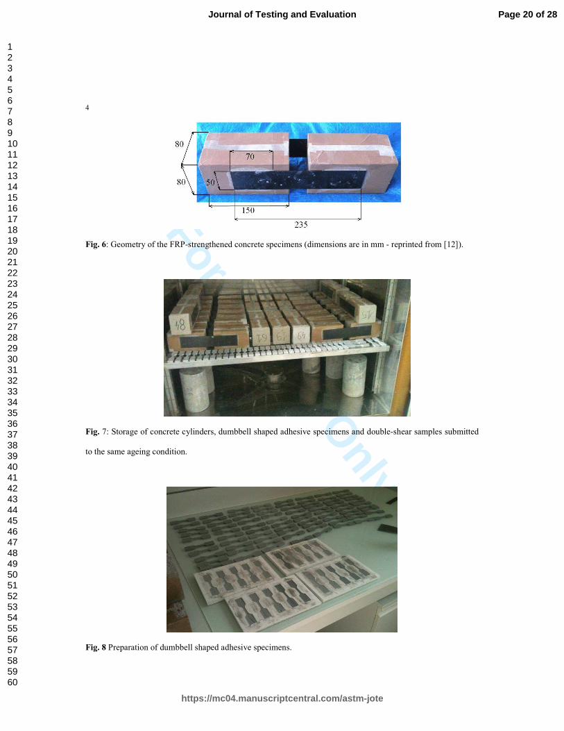
dimensions 80 x 80 x 150mm3 (see Fig. 6) connected together (with a separating gap of 35mm) by two CFRP
plates symmetrically bonded to the lateral faces.
Considering that most experimental campaigns based on shear test report that the concrete layer near the
bonded surface is the weakest part of the joint before ageing (cohesive failure in concrete is the usual failure
mode), it is then difficult to observe the ageing-induced evolution of the shear capacity of the bonded joint if the
FRP system is bonded on a low grade concrete. Therefore in this study, it was decided to use high strength
concrete to lower the ageing time necessary to sufficiently alter the adhesive layer to change the failure mode
and shear capacity. The same concrete mixture was used to cast the concrete blocks devoted to the preliminary
tests (in order to determine the best specimen geometry) as well as the blocks used in the durability study. All
these concrete prisms were prepared using type I Portland cement, water, sand and gravel with respective mass
ratios (with reference to the weight of cement) of 1.0:0.55:2.48:2.74. Maximum gravel size was 2 cm. At 28 days
of age, the mean cylinder compressive strength of the concrete was 63.6 MPa.
Page 5 of 28
https://mc04.manuscriptcentral.com/astm-jote
Journal of Testing and Evaluation
123456789101112131415161718192021222324252627282930313233343536373839404142434445464748495051525354555657585960
For Review O
nly
6
Commercially available pultruded CFRP plates [30] and a bi-component low temperature curing epoxy
adhesive [31] were used to prepare the specimens. This system (FRP and adhesive) is commonly used in the
field for the strengthening of civil structures by externally bonded CFRP plates. Before performing any bonding
operations, the laboratory staff received a one-day training period, provided by technical experts from SIKA
France. The main mechanical properties of the strengthening system and its components (FRP and adhesive) are
reported in the Technical Data Sheets provided by SIKA [30-31] and in the technical approval document
published by the French approval center [32]. Only the formed sides of the concrete prisms were used to bond
the CFRP plates. As prescribed in the technical data sheet, the concrete substrate was previously ground and
vacuum-cleaned before the application of a thin (approximately 1.5 mm) uniform layer of epoxy adhesive. A
similar layer of adhesive was also applied on the surface of the CFRP plate. No primer was used in accordance
with the manufacturer’s application guidelines. Then each plate was positioned on the concrete surface and
rolled, using a paint roller, to push out all air bubbles. To avoid premature corner failure of the concrete blocks
[33], plates were bonded with a gap of 30mm starting from the edge of each block. The bonding of the second
plate on each specimen was achieved one day after the bonding of the first plate. The surface area of each of the
four bonded joints was 70 x 50mm2. It is to note that the 7cm bonded length cannot provide the full capacity of
the system, considering that the anchorage length of such systems was measured to be approximately 10cm in a
previous study [34]. The geometry of the FRP-strengthened concrete specimens is presented on Fig. 6.
Finally, 168 concrete prisms of dimensions 80 x 80 x 150mm3 and 28 concrete cylinders were cast
respectively for the construction of 84 double-shear test specimens and for the measurement of concrete strength
at selected stages of ageing (Fig. 5).
The epoxy adhesive was cured at ambient temperature for at least 3 weeks before the beginning of the
durability study (i.e. before initial mechanical characterization of unaged specimens and beginning of the
exposure of the other specimens to the various ageing conditions).
Page 6 of 28
https://mc04.manuscriptcentral.com/astm-jote
Journal of Testing and Evaluation
123456789101112131415161718192021222324252627282930313233343536373839404142434445464748495051525354555657585960
For Review O
nly
7
2.2 Characterization of the constitutive materials
To monitor the property evolutions of concrete and polymer adhesive during hydrothermal ageing, specific
samples were prepared and stored with the double-shear samples in the climatic chambers (Fig. 7). Concrete
compressive strength was measured on 11cm-diameter by 22cm-tall cylinders. Moreover, tensile tests were
performed on dumbbell-shaped polymer samples (Fig. 8) in order to assess the possible degradation of the
tensile strength of the epoxy induced by accelerated ageing.
2.3 Ageing conditions
All specimens (FRP-strengthened concrete, concrete cylinders and polymer samples) were exposed to three
different hygrothermal conditions in various climatic chambers (Fig. 7). These environments consisted of:
• A constant relative humidity (RH) of 95% at a temperature of 40°C (climatic chamber N°1: CC1)
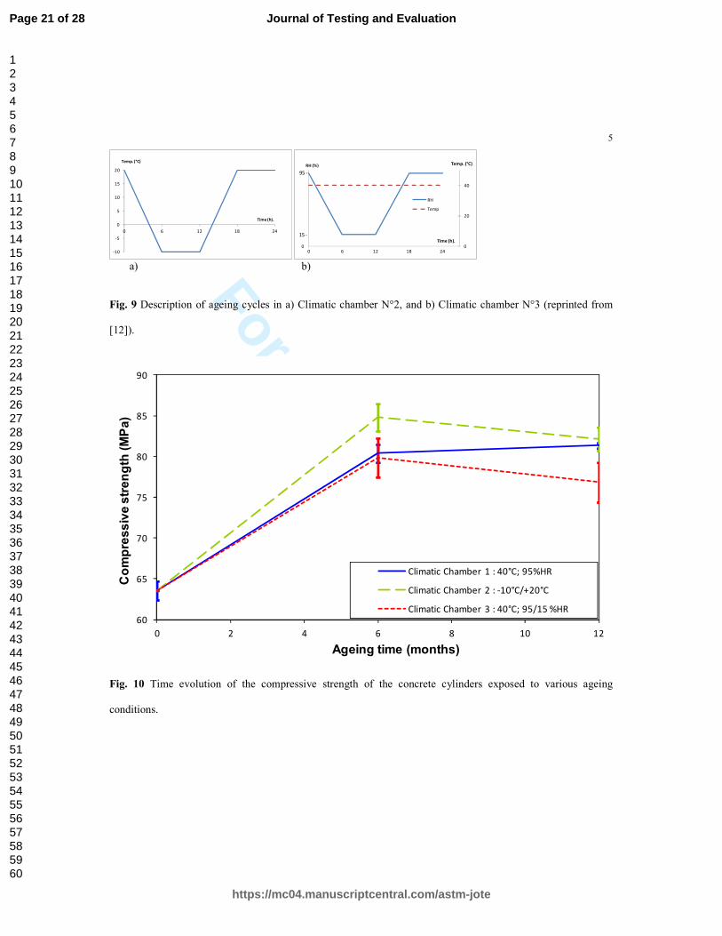
• Cycles of temperature, with temperature varying between -10°C and +20°C (see Fig. 9.a), without humidity
control (climatic chamber N°2: CC2);
• Cycles of relative humidity, with relative humidity varying between 15% and 95% at a constant temperature
of 40°C (see Fig. 9.b; climatic chamber N°3: CC3).
These ageing conditions were chosen considering that i) the water absorbed by the epoxy adhesive may affect
the mechanical performance of the CFRP/concrete adhesive bond, that ii) the chosen temperature of 40°C
accelerates water sorption kinetics, while remaining below the glass transition temperature of the epoxy
adhesive, and that iii) exposure to subzero temperatures and freeze-thaw cycles may also contribute to a
degradation of the bond properties.
The climatic chambers were controlled in temperature and humidity, using the dedicated software provided
by the manufacturer, and the daily thermal cycles described in Fig. 9 were continuously run during one year.
Samples were removed periodically from the various climatic chambers and the evolutions of their bond
properties were investigated over the 12-month period of study. The experimental program is summarized in
Table 1.
Page 7 of 28
https://mc04.manuscriptcentral.com/astm-jote
Journal of Testing and Evaluation
123456789101112131415161718192021222324252627282930313233343536373839404142434445464748495051525354555657585960
For Review O
nly
8
3 Experimental results
In this section, the effects of ageing conditions on the property evolutions of polymer and concrete, considered in
this study to be the two weakest constituents of the FRP-strengthened concrete specimens, are first investigated.
Then, the second part of the section focuses on the evolutions of the FRP-concrete bond properties when subjected to
the same environments.
3.1 Evolution of concrete and adhesive
The evolutions of constitutive material properties were determined by testing four concrete cylinders and six
dumbbell shaped adhesive specimens at each scheduled time period and for each type of ageing condition. The
results of these characterizations over the 12-month ageing period are presented in Fig. 10 and Fig. 11. To
simplify the analysis, all the values presented in the following figures and related to aged specimens (except for
Fig. 10) are normalized with respect to corresponding control values (related to unaged specimens). Error bars
are plotted based on standard deviations calculated for each series of samples. The stages of ageing under
consideration are 0, 6 and 12 months for the measurement of compressive strength while tensile tests on epoxy
specimens were performed after 0, 2, 4, 8 and 12 months. The initial time (0 month) corresponds to the moment
when the samples are first exposed to the chosen environmental conditions. It also refers to 28 days after casting
for the concrete cylinders and three weeks after fabrication for the bulk adhesive samples. The three week period
of cure of the epoxy was chosen considering that the technical data sheet still reports slight changes in its
mechanical properties after a curing period of 7-14 days at room temperature. Both concrete and adhesive
samples were cured in laboratory conditions (21±2°C, 50% RH).
In view of the three available ageing stages (0; 6 and 12 months),the property evolution of the concrete can
only be discussed considering two ageing periods (0 to 6 months and 6 to 12 months). As a first result, it appears
that concrete strength increases, whatever the ageing conditions, during the initial period of ageing and then
slightly degrades (for CC2 and CC3 storage conditions) or slightly continues to increase for samples stored in
CC1.
Page 8 of 28
https://mc04.manuscriptcentral.com/astm-jote
Journal of Testing and Evaluation
123456789101112131415161718192021222324252627282930313233343536373839404142434445464748495051525354555657585960
For Review O
nly
9
The continuous strength development observed for concrete stored in CC1 is an expected trend due to the
ageing condition that offers adequate amount of moisture for a continuous hydration process. In the second
period of ageing in CC2, it is believed that freeze-thaw cycling damages the concrete, leading to a reduction in
tensile strength. However, no clear explanation is proposed for the strength reduction of concrete during the
second period of storage in CC3. Considering that the most commonly reported failure mode encountered in
adhesive bond tests is concrete delamination, these results are of significant interest.
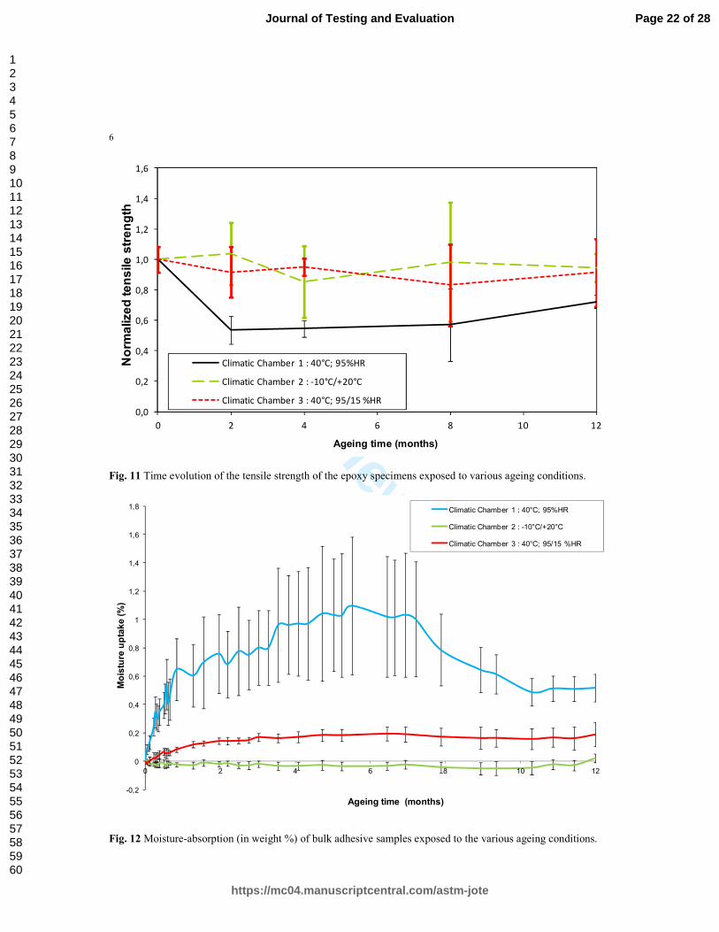
After analyzing the results presented in Fig. 11, it was observed that time evolution of the tensile strength of
epoxy specimens stored in CC2 and CC3 remains roughly unchanged over the 12-month ageing period, although
there is some scatter in the data. However, epoxy samples exposed to the high and constant relative humidity
condition of CC1 exhibit rapid strength degradation over the first 2 months. After this period of 2 months, their
tensile strength slightly but continuously re-increase.
To investigate the possible correlation between tensile strength evolutions and moisture absorptions, fifteen
dumbbell shaped adhesive samples were specially fabricated to investigate the moisture uptake under ageing
conditions. All these bulk specimens were weighed before being stored in climatic chambers. Five samples were
placed in each chamber. Then, polymer samples were periodically weighed, and the moisture uptake of a
specimen i at the time t was calculated using:
100
0
0×
−=
w
wwM i
iiti
t (1)
where:
wi0 is the weight of the sample i before ageing
wit is the weight of the sample i at the time t
The time evolutions of the moisture uptake of the adhesive exposed to the three studied ageing conditions are
shown in Fig. 12. As expected, the higher moisture uptake was evidenced for specimens submitted to the ageing
condition provided by CC1. These samples reach a saturation state with maximum moisture uptake around 1%
after 150 days of exposure. Surprisingly, the storage condition in CC2 produced a weight loss, but recorded
changes are very low. With regard to CC3 condition, the moisture absorption of samples reaches an asymptotic
Page 9 of 28
https://mc04.manuscriptcentral.com/astm-jote
Journal of Testing and Evaluation
123456789101112131415161718192021222324252627282930313233343536373839404142434445464748495051525354555657585960
For Review O
nly
10
level of approximately 0.2 % after 6 months. However, it can be considered that the mass of bulk samples stored
in CC2 and CC3 remained roughly unchanged over the 12-month ageing period compared to the changes
observed for samples exposed in CC1.
By comparing curves presented in Fig. 11 and Fig. 12, similar trends are observed, in particular globally
unchanged tensile strength and moisture uptake for samples stored in CC2 and CC3 and a two period behavior of
CC1 samples (first period with weight gain and tensile strength loss followed by a second period characterized
by weight loss and partial recovery of tensile strength). Even if the phase of weight gain is longer than the phase
of tensile strength loss, respectively 2 and 6 months, it is believed that the two phenomena are strongly linked, as
already observed in many publications (for example [35]). When water alters the mechanical properties of the
polymer in a reversible manner, it is usually attributed to a plasticization of the polymer network by water
molecules [36-37].
These results are in line with those reported by Benzarti et al. in [9]. These authors showed that polymer
samples exposed to ageing conditions similar to those in CC1 (moisture saturated air, temperature of 40°C) are
subjected to 2 antagonistic phenomena:
- a plasticization effect by water, related to the breakage of physical interactions, leading both to a decrease in
the mechanical properties (tensile strength and Young’s modulus) and in the glass transition temperature (Tg)
of the polymer.
- a crosslinking effect, related to the reaction of residual monomers, which is favored by both the temperature
of 40°C and the increased molecular mobility due to plasticization. This mechanism has opposite effects,
with increases in both mechanical properties and Tg.
In the present study, plasticization seems to be the predominant mechanism during the first stage of ageing in
CC1 (0-2 months), as the sorption kinetics is high during this period (Fig. 12). Then, after water saturation of the
polymer, crosslinking becomes progressively predominant, and leads ultimately to a partial recovery of the
tensile strength.
Page 10 of 28
https://mc04.manuscriptcentral.com/astm-jote
Journal of Testing and Evaluation
123456789101112131415161718192021222324252627282930313233343536373839404142434445464748495051525354555657585960
For Review O
nly
11
3.2 Evolution of FRP-concrete bond failure
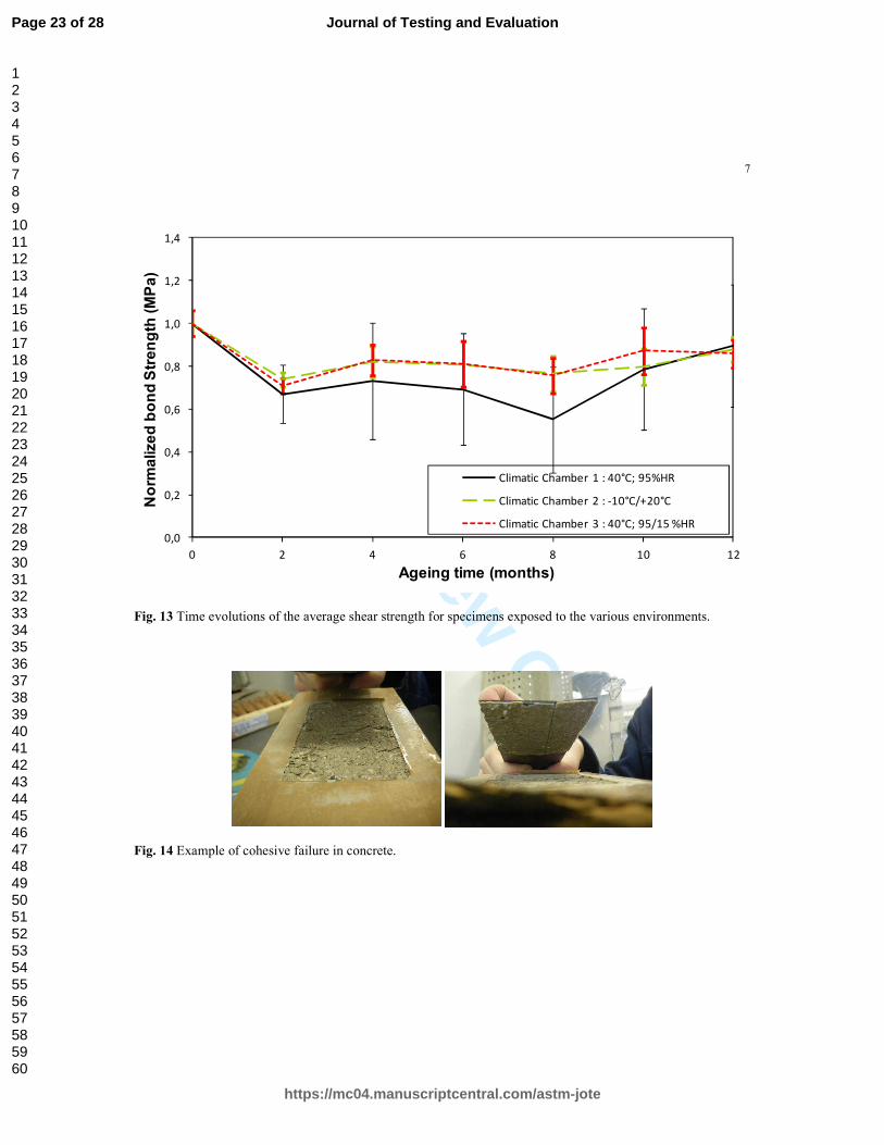
The evolutions of the average shear strength of aged specimens are illustrated in Fig. 13 for each
environmental conditions considered in this study. As a first result, it can be noticed that there is a large
dispersion of experimental average bond strength values especially for samples stored in CC1. However,
whatever the ageing condition, it is possible to observe a slight decrease in the average shear strength during the
early period of exposure (in respectively the first 8 months for samples stored in CC1 and the first 2 months for
samples stored in CC2 or in CC3). During the early period, cyclic exposure conditions in CC2 and CC3 induce
very similar effects, when exposure in CC1 (40°C and 95% R.H.) produces a more significant degradation of the
bond properties. After this first period, all the bond strength curves showed an increase, and at the end of the 12-
month exposure time, bond strength capacities were approximately restored up to 89%, 88% and 86% for
samples stored in CC1, CC2 and CC3 respectively.
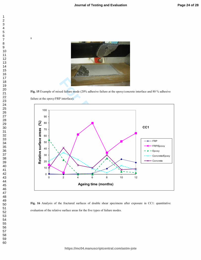
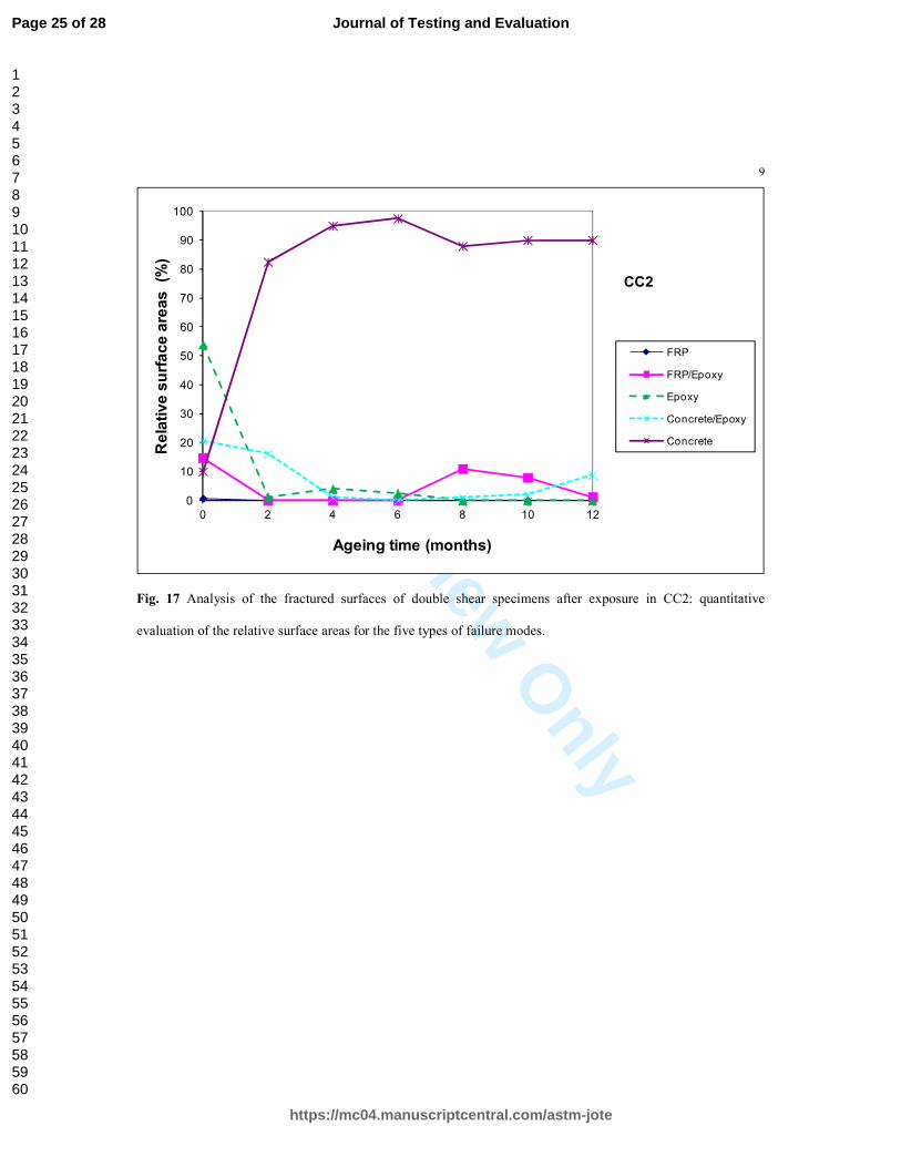
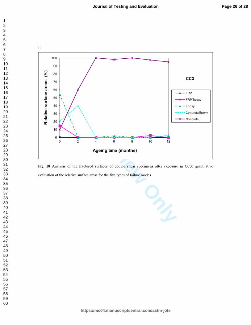
Moreover, a careful observation of the fractured surfaces indicated an evolution of the shear failure mode of
specimens after ageing, whatever the type of environment. To analyse more precisely this phenomenon, each
fracture pattern was observed considering five types of failure: cohesive failure in concrete, adhesive failure at
the epoxy/concrete interface, cohesive failure in the epoxy layer, adhesive failure at the epoxy/FRP interface and
interlaminar failure within the FRP. The surface areas of failure bond were visually evaluated and quantified (see
for example Fig. 14 and Fig. 15). Results of these observations are shown in Fig. 16, Fig. 17 and Fig. 18 for
fracture patterns of samples exposed to environmental conditions of CC1, CC2 and CC3 respectively.
From the observation of fractured surfaces, it appears that the initial failure mode was mostly mixed failure
(see T0 in Fig. 16 and Fig. 17) and shifted to concrete failure after ageing in CC2 and CC3. With respect to the
positive evolution of the concrete properties over ageing (Fig. 10), these results seem to indicate that the bond
properties of the adhesive are not significantly altered by ageing in CC2 and CC3. This conclusion is
corroborated by the mostly unchanged tensile strength of the bulk epoxy specimens exposed to the same ageing
conditions. It can also be suspected that the ageing conditions in CC2 and CC3 are detrimental to the external
layers of the concrete prisms, while having no significant effect on bulk concrete in the core of the concrete
cylinders, (which represents a relatively high volume).
Page 11 of 28
https://mc04.manuscriptcentral.com/astm-jote
Journal of Testing and Evaluation
123456789101112131415161718192021222324252627282930313233343536373839404142434445464748495051525354555657585960
For Review O
nly
12
As previously discussed, the bulk epoxy samples stored in CC1 are the only ones exhibiting a significant loss
of tensile strength associated with a moisture induced plasticization, over the first months of ageing. This is
consistent with the decrease in the shear capacity of the joint observed for CFRP/concrete assemblies exposed to
CC1 conditions. As stated previously in section 3.1, the crosslinking mechanism of the polymer adhesive
becomes more predominant over plasticization as the sorption process reaches saturation, which may explain the
partial recovery of the shear strength of the bonded joints on the long term. However, due to all these
mechanisms, no predominant mode of failure is observed (see Fig. 16). It is also believed that the external layers
of the concrete prisms of the FRP-strengthened concrete specimens are not significantly affected by the
conditions provided by CC1, contrary to the surface damage suspected for the concrete prisms stored in CC2 and
CC3. Concrete failure is then rarely observed for FRP-strengthened concrete specimens under ageing conditions
provided by CC1.
4 Conclusions
The results of an experimental study on the degradation of the adhesive bond between CFRP plates and concrete
under accelerated ageing conditions are presented. Test specimens were exposed to various ageing conditions,
i.e. saturated moist air at 95% RH, hygric cycles and freeze-thaw cycles. The evolutions of the bond properties
were monitored by performing double lap shear tests at periodic intervals, while changes in the mechanical
properties of the weakest constituent materials, namely the bulk polymer adhesive and the concrete, were
investigated by means of tensile and compressive tests respectively. A new geometry of double-shear test
specimens is proposed, which restricts the possible variation of the effective transfer length that may compensate
the decrease in the mechanical properties of the polymer adhesive during ageing. In this way, it is ensured that
the double shear test is actually sensitive to variations in the adhesive properties. It is to note that in a previous
study [9] carried-out on concrete samples strengthened with the same CFRP systems as in this research and
involving an ageing condition similar to that found in the climatic chamber 1, authors reported that no evolution
of the shear capacity was observed after 1 year of ageing for specimens designed with a 200mm FRP bonded
length. With the proposed new geometry of sample (with small bonded length), it was possible to observe a
Page 12 of 28
https://mc04.manuscriptcentral.com/astm-jote
Journal of Testing and Evaluation
123456789101112131415161718192021222324252627282930313233343536373839404142434445464748495051525354555657585960
For Review O
nly
13
slight decrease in the average shear strength during the first 8 months of samples stored in CC1. From the
authors’ point of view, this result justifies the proposed experimental procedure.
The results of the mechanical tests carried out over the 12-month ageing period show that
- Only small reductions in tensile strength were observed for bulk adhesive samples exposed to freeze-
thaw and hygric cycles (residual strengths were respectively 95% and 91%, with respect to initial
strength).
- After a first period of tensile strength loss (roughly during the first two months of ageing), a partial
recovery was observed for bulk adhesive samples subjected to constant humidity conditions (95% R.H.,
at 40°C). At the end of the 12-month ageing period in these conditions, a residual tensile strength of
72% was measured.
- Trends observed for evolutions of the tensile strength of bulk adhesive samples seem highly correlated
to water absorption: the higher the moisture uptake, the higher the reduction in tensile strength.
Moreover, the curves describing moisture absorption and strength loss exhibit almost identical two-
period evolutions with reversible behaviors (even if the duration of periods was different). In
accordance with previous studies, such a behavior can be explained by a competition between 2
antagonistic phenomena, i.e. a plasticization of the adhesive driven by moisture ingress, and a
crosslinking mechanism due to the reaction of residual monomers which becomes more predominant
when the sorption process reaches saturation.
- Whatever the ageing condition, only a limited reduction in the average shear strength was observed for
bonded assemblies at the end of the 12-month ageing period (residual values of 89%, 87% and 85%
with respect to initial bond properties, after exposure to constant humidity, freeze-thaw cycles and
hygric cycles, respectively). However, a higher loss of the shear capacity was observed under constant
humidity at intermediate period (roughly, after 8 months), suggesting that prolonged exposure to
moisture is the most detrimental condition. Nevertheless, a partial recovery is also observed in the long
term, which can be attributed to a crosslinking mechanism similar to that evidenced for the bulk
adhesive samples.
- For double shear specimens subjected to constant humidity conditions, deterioration mechanisms
related to moisture ingress in the epoxy network / at interfaces are complex and result in multiple failure
Page 13 of 28
https://mc04.manuscriptcentral.com/astm-jote
Journal of Testing and Evaluation
123456789101112131415161718192021222324252627282930313233343536373839404142434445464748495051525354555657585960
For Review O
nly
14
modes, as evidenced by the analysis of the fracture patterns on tested samples. Differently, concrete
failure remains the predominant failure mode on the fractured surfaces of specimens subjected to the
other ageing conditions.
References
[1] Meier, U., and Kaiser, H.-P., “Strengthening of structure with CFRP laminates,” ASCE specialty conference
Advanced composite materials in civil engineering structures, S. L. Iyer, and R. Sen, Eds., Las Vegas, NV. 1991.
[2] Fib, “Externally bonded FRP reinforcement for RC structures,” Fédération Internationale du Béton fib-Bulletin 14,
Lausanne, Switzerland, 2001.
[3] National Research Council, CNR-DT 200/2004 “Guide for the design and construction of externally bonded FRP
systems for strengthening existing structures,” 2004.
[4] ACI Committee 440.2R-08 “Guide for the Design and Construction of Externally Bonded FRP Systems for
Strengthening Concrete Structures,” 2008.
[5] AFGC, “Réparation et renforcement des structures en béton au moyen des matériaux composites.
Recommandations provisoires,” Bulletin scientifique et technique de l’Association française de génie civil (in
french), 2011.
[6] Sen, R., “Developments in the durability of FRP-concrete bond,” Constr Build Mater, Vol. 78, 2015, pp. 112–125.
[7] Chu, W., Wu, L., and Karbhari, V. M., “Durability evaluation of moderate temperature cured E-glass/vinylester
systems,” Compos. Struct., Vol. 66, 2004, pp. 367–376.
[8] Abanilla, M. A., Li, Y., and Karbhari, V. M., “Durability characterization of wet layup graphite/epoxy composites
used in external strengthening,” Compos. Part B: Eng., Vol. 37, No. 2, 2005, pp. 200–212.
[9] Benzarti, K., Chataigner, S., Quiertant, M., Marty, C., and Aubagnac, C., “Accelerated ageing behaviour of the
adhesive bond between concrete specimens and CFRP overlays,” Constr Build Mater, Vol. 25, No. 2, Sp. Iss, 2011,
pp. 523-538.
[10] Sen, R., “Developments in the durability of FRP-concrete bond,” Constr Build Mater, Vol. 78, 2015, pp. 112–125.
[11] Pan, Y., Xian, G., and Silva, M. A. G., “Effects of water immersion on the bond behavior between CFRP plates and
concrete substrate,” Constr Build Mater, Vol. 101, 2015, pp. 326–337.
Page 14 of 28
https://mc04.manuscriptcentral.com/astm-jote
Journal of Testing and Evaluation
123456789101112131415161718192021222324252627282930313233343536373839404142434445464748495051525354555657585960
For Review O
nly
15
[12] Quiertant, M., Benzarti, K., Landrin, F., Landrin, M., Schneider, J., Boinski, F., “Durability of FRP to concrete
bonded interface under accelerated ageing” 8th RILEM International Conference on Mechanisms of Cracking and
Debonding in Pavements, A. Chabot, W.G., Buttlar, E.V., Dave, C., Petit, G. Tebaldi, Eds., Springer Netherlands,
2016, pp. 605-611.
[13] Lau, D., and Büyüköztürk, O., “Fracture characterization of concrete/epoxy interface affected by moisture,”
Mechanics of Materials, Vol. 42, 2010, pp. 1031–1042.
[14] Shrestha, J., Ueda, T., and Zhang, D. “Durability of FRP Concrete Bonds and Its Constituent Properties under the
Influence of Moisture Conditions,” J. Mater. Civ. Eng., Vol. 27, No. 2, 2015, A4014009
[15] Yun, Y., and Wu, Y.-F., “Durability of CFRP–concrete joints under freeze–thaw cycling,” Cold Reg. Sci. Technol.,
Vol. 65, 2011, pp. 401–412.
[16] Karbhari, V.M., and Engineer, M., “Investigation of bond between concrete and composites: use of a peel test,” J.
Reinforced Plast. Compos., Vol. 15, No 2, 1996, pp. 208–227.
[17] Davalos, J.F., Kodkani, S.S., Ray, I., and Boyajian, D.M., 2005. “A fracture mechanic approach for interface
durability of bonded FRP to concrete,” presented at the 7th Int. Symp. on FRP Reinforcement for R.C. Structures
(FRPRCS-7). ACI, Kansas City, Kan, USA, pp. 1465–1479.
[18] Kolluru, V., Ali-Ahmad, M., and Ghosn, M., “Freeze–thaw degradation of FRP–concrete interface: impact on
cohesive fracture response,” Eng. Fract. Mech., Vol. 75, 2008, pp. 3924–3940.
[19] Green, M.F., Soudki, K.A., and Johnson, M.M., “Freeze–thaw behaviour of reinforce concrete beams strengthened
by fibre reinforced plastic sheets,” Proc. Canadian Soci. Civ. Eng., Sherbrooke. 27–30 May 1997.
[20] Mukhopadhyaya, P., Swamy, R.N., and Lynsdale, C.J., “Influence of aggressive exposure conditions on the
behaviour of adhesive bonded concrete–GFRP joints,” Constr. Build. Mater., Vol. 18, No 12, 1998, pp. 427–446.
[21] Green, M.F., Bisby, L.A., Beaudoin, Y., and Labossiere, P., “Effect of freeze–thaw cycles on the bond durability
between fibre reinforced polymer plate reinforcement and concrete,” Can. J. Civ. Eng., Vol. 27, 2000, pp. 949–959.
[22] Bisby, L.A., and Green, M.F., “Resistance to freezing and thawing of fiber–reinforced polymer–concrete bond,”
ACI Struct. J. Vol. 99, No 2, 2002, pp. 215–223.
[23] Pavel, D., “Environmental durability of FRP bond to concrete subjected to freeze–thaw action,” M. Phil. thesis,
Massachusetts Institute of Technology, 2006.
[24] Yao, J., Teng, J.G., and Chen, J.F., “Experimental study on FRP-to-concrete bonded joints,” Compos. Part B: Eng.,
Vol. 36, No. 2, 2005, pp. 99–113.
[25] Leone, M., Matthys, S., and Aiello, M-A., “Effect of elevated service temperature on bond between FRP EBR
systems and concrete,” Compos. Part B, Vol. 40, No. 1, 2009, pp. 85–93.
Page 15 of 28
https://mc04.manuscriptcentral.com/astm-jote
Journal of Testing and Evaluation
123456789101112131415161718192021222324252627282930313233343536373839404142434445464748495051525354555657585960
For Review O
nly
16
[26] Serbescu, A., Guadagnini, M., and Pilakoutas, K., “Standardised double-shear test for determining bond of FRP to
concrete and corresponding model development” Compos. Part B, Vol. 55, 2013, pp. 277–297.
[27] Ferrier, E., Quiertant, M., Benzarti, K., and Hamelin, P., “Influence of the properties of externally bonded CFRP on
the shear behavior of concrete/composite adhesive joints,” Compos. Part B: Eng., Vol 41, No. 5, 2010, pp. 354-
362.
[28] Japanese Concrete Institute. Report II of research committee on continuous fiber-reinforced concrete, vol. 5, 1998.
[29] Aydin, H., Gravina, R. J., and Visintin, P., “Durability of Adhesively Bonded FRP-to-Concrete Joints,” J. Compos.
Constr., Vol. 20, No 5, 2016, 04016016
[30] Sika Corporation US Sika CarboDur® Carbon fiber laminate for structural strengthening. Product Data Sheet
Edition 5.4. 2011.
[31] SIKA Distributor Sikadur® 30 High-modulus, high-strength, structural epoxy paste adhesive for use with Sika®
CarboDur® reinforcement.
[32] CSTB, Avis Technique 3/10-669 Sika CarboDur® SikaWrap® 026, Available from:
https://archive.org/details/22FrAtSikaCarbodurSikaWrap
[33] Chataigner, S., Caron, J.-F., Benzarti, K., Quiertant, M., and Aubagnac, C., “Characterization of composite to
concrete bonded interface. Description of the single lap shear test,” Eur J Environ Civil Eng, Vol. 13, No 9, 2009,
pp. 1073–1082.
[34] Chataigner, S., Caron, J.-F., Benzarti, K., Quiertant, M., and Aubagnac, C., “Use of a single lap shear test to
characterize composite-to-concrete or composite-to-steel bonded interfaces.” Constr Build Mater, Vol. 25, No. 2,
Sp. Iss, 2011, pp. 468-478.
[35] Shaw, S. J., Epoxy resin adhesives. In: Ellis B, editor. Chemistry and technology of epoxy resins. London: Blackie
Academic & Professional 1994. p. 206–55.
[36] Frigione, M., Aiello, M. A., and Naddeo, C., “Water effects on the bond strength of concrete/concrete adhesive
joints,” Constr. Build. Mater., Vol. 20, 2006, pp. 957–970.
[37] Zhou, J., and Lucas, J.-P., “Hygrothermal effects of epoxy resins. Part I: the nature of water in epoxy,” Polymer,
1999, Vol. 40, 1999, pp. 5505–5512.
Page 16 of 28
https://mc04.manuscriptcentral.com/astm-jote
Journal of Testing and Evaluation
123456789101112131415161718192021222324252627282930313233343536373839404142434445464748495051525354555657585960
For Review O
nly
List of figure captions
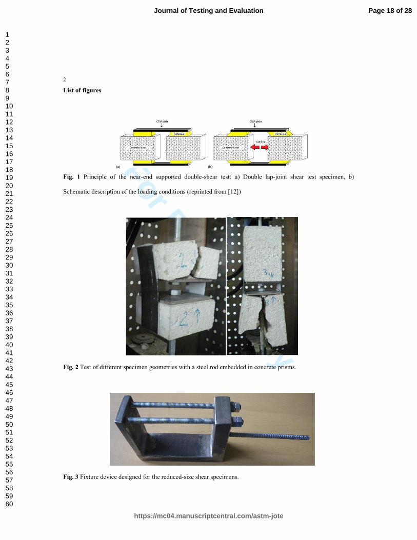
Fig. 1 Principle of the near-end supported double-shear test: a) Double lap-joint shear test specimen, b)
Schematic description of the loading conditions (reprinted from [12])
Fig. 2 Test of different specimen geometries with a steel rod embedded in concrete prisms.
Fig. 3 Fixture device designed for the reduced-size shear specimens.
Fig. 4. Test setup for the double lap shear experiments (reprinted from [12]).
Fig. 5. Concrete blocks after removal from the formworks (reprinted from [12]).
Fig. 6: Geometry of the FRP-strengthened concrete specimens (dimensions are in mm - reprinted from [12]).
Fig. 7 Storage of concrete cylinders, dumbbell shaped adhesive specimens and double-shear samples submitted
to the same ageing condition.
Fig. 8 Preparation of dumbbell shaped adhesive specimens.
Fig. 9 Description of ageing cycles in a) Climatic chamber N°2, and b) Climatic chamber N°3 (reprinted from
[12]).
Fig. 10 Time evolution of the compressive strength of the concrete cylinders exposed to various ageing
conditions.
Fig. 11 Time evolution of the tensile strength of the epoxy specimens exposed to various ageing conditions.
Fig. 12 Moisture-absorption (in weight %) of bulk adhesive samples exposed to the various ageing conditions.
Fig. 13 Time evolutions of the average shear strength for specimens exposed to the various environments.
Fig. 14 Example of cohesive failure in concrete.
Fig. 15 Example of mixed failure mode (20% adhesive failure at the epoxy/concrete interface and 80 % adhesive
failure at the epoxy/FRP interface).
Fig. 16 Analysis of the fractured surfaces of double shear specimens after exposure in CC1: quantitative
evaluation of the relative surface areas for the five types of failure modes.
Fig. 17 Analysis of the fractured surfaces of double shear specimens after exposure in CC2: quantitative
evaluation of the relative surface areas for the five types of failure modes.
Fig. 18 Analysis of the fractured surfaces of double shear specimens after exposure in CC3: quantitative
evaluation of the relative surface areas for the five types of failure modes.
Page 17 of 28
https://mc04.manuscriptcentral.com/astm-jote
Journal of Testing and Evaluation
123456789101112131415161718192021222324252627282930313233343536373839404142434445464748495051525354555657585960
For Review O
nly
2
List of figures
(a) (b)
Fig. 1 Principle of the near-end supported double-shear test: a) Double lap-joint shear test specimen, b)
Schematic description of the loading conditions (reprinted from [12])
Fig. 2 Test of different specimen geometries with a steel rod embedded in concrete prisms.
Fig. 3 Fixture device designed for the reduced-size shear specimens.
Page 18 of 28
https://mc04.manuscriptcentral.com/astm-jote
Journal of Testing and Evaluation
123456789101112131415161718192021222324252627282930313233343536373839404142434445464748495051525354555657585960
For Review O
nly
3
Fig. 4. Test setup for the double lap shear experiments (reprinted from [12]).
Fig. 5. Concrete blocks after removal from the formworks (reprinted from [12]).
Page 19 of 28
https://mc04.manuscriptcentral.com/astm-jote
Journal of Testing and Evaluation
123456789101112131415161718192021222324252627282930313233343536373839404142434445464748495051525354555657585960
For Review O
nly
4
Fig. 6: Geometry of the FRP-strengthened concrete specimens (dimensions are in mm - reprinted from [12]).
Fig. 7: Storage of concrete cylinders, dumbbell shaped adhesive specimens and double-shear samples submitted
to the same ageing condition.
Fig. 8 Preparation of dumbbell shaped adhesive specimens.
Page 20 of 28
https://mc04.manuscriptcentral.com/astm-jote
Journal of Testing and Evaluation
123456789101112131415161718192021222324252627282930313233343536373839404142434445464748495051525354555657585960
For Review O
nly
5
-10
-5
0
5
10
15
20
0 6 12 18 24
Temp. (°C)
Time (h).
0
20
40
00 6 12 18 24
Temp. (°C)RH (%)
Time (h).
RH
Temp
15 -
95 -
a) b)
Fig. 9 Description of ageing cycles in a) Climatic chamber N°2, and b) Climatic chamber N°3 (reprinted from
[12]).
60
65
70
75
80
85
90
0 2 4 6 8 10 12
Compressive strength (MPa)
Ageing time (months)
Climatic Chamber 1 : 40°C; 95%HR
Climatic Chamber 2 : -10°C/+20°C
Climatic Chamber 3 : 40°C; 95/15 %HR
Fig. 10 Time evolution of the compressive strength of the concrete cylinders exposed to various ageing
conditions.
Page 21 of 28
https://mc04.manuscriptcentral.com/astm-jote
Journal of Testing and Evaluation
123456789101112131415161718192021222324252627282930313233343536373839404142434445464748495051525354555657585960
For Review O
nly
6
0,0
0,2
0,4
0,6
0,8
1,0
1,2
1,4
1,6
0 2 4 6 8 10 12
Norm
alized tensile strength
Ageing time (months)
Climatic Chamber 1 : 40°C; 95%HR
Climatic Chamber 2 : -10°C/+20°C
Climatic Chamber 3 : 40°C; 95/15 %HR
Fig. 11 Time evolution of the tensile strength of the epoxy specimens exposed to various ageing conditions.
-0,2
0
0,2
0,4
0,6
0,8
1
1,2
1,4
1,6
1,8
0 2 4 6 8 10 12
Moisture uptake (%)
Ageing time (months)
Climatic Chamber 1 : 40°C; 95%HR
Climatic Chamber 2 : -10°C/+20°C
Climatic Chamber 3 : 40°C; 95/15 %HR
Fig. 12 Moisture-absorption (in weight %) of bulk adhesive samples exposed to the various ageing conditions.
Page 22 of 28
https://mc04.manuscriptcentral.com/astm-jote
Journal of Testing and Evaluation
123456789101112131415161718192021222324252627282930313233343536373839404142434445464748495051525354555657585960
For Review O
nly
7
0,0
0,2
0,4
0,6
0,8
1,0
1,2
1,4
0 2 4 6 8 10 12
Norm
alized bond Strength (MPa)
Ageing time (months)
Climatic Chamber 1 : 40°C; 95%HR
Climatic Chamber 2 : -10°C/+20°C
Climatic Chamber 3 : 40°C; 95/15 %HR
Fig. 13 Time evolutions of the average shear strength for specimens exposed to the various environments.
Fig. 14 Example of cohesive failure in concrete.
Page 23 of 28
https://mc04.manuscriptcentral.com/astm-jote
Journal of Testing and Evaluation
123456789101112131415161718192021222324252627282930313233343536373839404142434445464748495051525354555657585960
For Review O
nly
8
Fig. 15 Example of mixed failure mode (20% adhesive failure at the epoxy/concrete interface and 80 % adhesive
failure at the epoxy/FRP interface).
0
10
20
30
40
50
60
70
80
90
100
0 2 4 6 8 10 12
Relative surface areas (%
)
Ageing time (months)
CC1
FRP
FRP/Epoxy
Epoxy
Concrete/Epoxy
Concrete
Fig. 16 Analysis of the fractured surfaces of double shear specimens after exposure in CC1: quantitative
evaluation of the relative surface areas for the five types of failure modes.
Page 24 of 28
https://mc04.manuscriptcentral.com/astm-jote
Journal of Testing and Evaluation
123456789101112131415161718192021222324252627282930313233343536373839404142434445464748495051525354555657585960
For Review O
nly
9
0
10
20
30
40
50
60
70
80
90
100
0 2 4 6 8 10 12
Relative surface areas (%
)
Ageing time (months)
CC2
FRP
FRP/Epoxy
Epoxy
Concrete/Epoxy
Concrete
Fig. 17 Analysis of the fractured surfaces of double shear specimens after exposure in CC2: quantitative
evaluation of the relative surface areas for the five types of failure modes.
Page 25 of 28
https://mc04.manuscriptcentral.com/astm-jote
Journal of Testing and Evaluation
123456789101112131415161718192021222324252627282930313233343536373839404142434445464748495051525354555657585960
For Review O
nly
10
0
10
20
30
40
50
60
70
80
90
100
0 2 4 6 8 10 12
Relative surface areas (%
)
Ageing time (months)
CC3
FRP
FRP/Epoxy
Epoxy
Concrete/Epoxy
Concrete
Fig. 18 Analysis of the fractured surfaces of double shear specimens after exposure in CC3: quantitative
evaluation of the relative surface areas for the five types of failure modes.
Page 26 of 28
https://mc04.manuscriptcentral.com/astm-jote
Journal of Testing and Evaluation
123456789101112131415161718192021222324252627282930313233343536373839404142434445464748495051525354555657585960
For Review O
nly
11
List of table captions
Table 1: Experimental program
Page 27 of 28
https://mc04.manuscriptcentral.com/astm-jote
Journal of Testing and Evaluation
123456789101112131415161718192021222324252627282930313233343536373839404142434445464748495051525354555657585960
For Review O
nly
12
List of tables
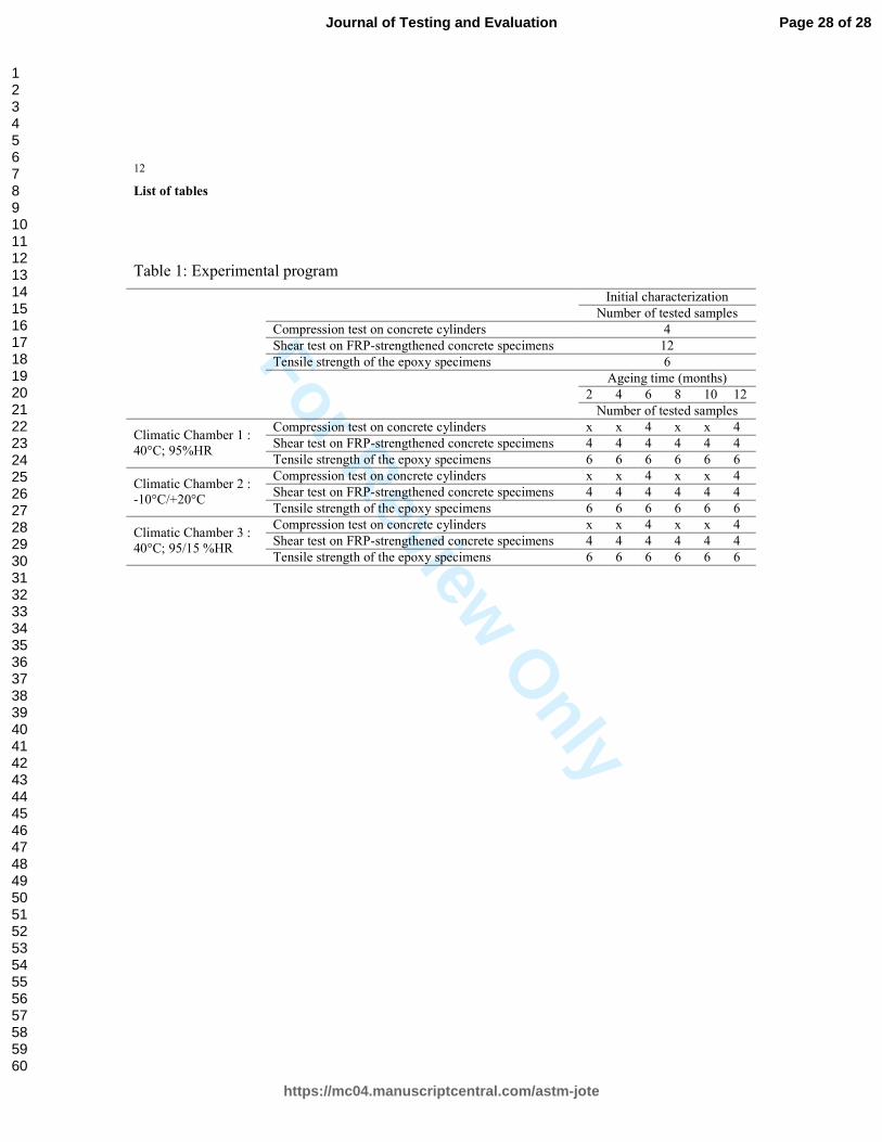
Table 1: Experimental program
Initial characterization
Number of tested samples
Compression test on concrete cylinders 4
Shear test on FRP-strengthened concrete specimens 12
Tensile strength of the epoxy specimens 6
Ageing time (months)
2 4 6 8 10 12
Number of tested samples
Climatic Chamber 1 :
40°C; 95%HR
Compression test on concrete cylinders x x 4 x x 4
Shear test on FRP-strengthened concrete specimens 4 4 4 4 4 4
Tensile strength of the epoxy specimens 6 6 6 6 6 6
Climatic Chamber 2 :
-10°C/+20°C
Compression test on concrete cylinders x x 4 x x 4
Shear test on FRP-strengthened concrete specimens 4 4 4 4 4 4
Tensile strength of the epoxy specimens 6 6 6 6 6 6
Climatic Chamber 3 :
40°C; 95/15 %HR
Compression test on concrete cylinders x x 4 x x 4
Shear test on FRP-strengthened concrete specimens 4 4 4 4 4 4
Tensile strength of the epoxy specimens 6 6 6 6 6 6
Page 28 of 28
https://mc04.manuscriptcentral.com/astm-jote
Journal of Testing and Evaluation
123456789101112131415161718192021222324252627282930313233343536373839404142434445464748495051525354555657585960