Embed Size (px)
Citation preview

Research ArticleEffect of Neutral Grounding Protection Methods for CompensatedWind/PV Grid-Connected Hybrid Power Systems
Nurettin Çetinkaya1 and Farhana Umer2
1Nurettin ÇETINKAYA, Electrical-Electronics Engineering Department, Selçuk University, Konya, Turkey2Farhana UMER, Electrical Engineering Department, The Islamia University of Bahawalpur Pakistan, Bahawalpur, Pakistan
Correspondence should be addressed to Nurettin Çetinkaya; [email protected]
Received 3 June 2017; Revised 5 September 2017; Accepted 9 October 2017; Published 19 November 2017
Academic Editor: Leonardo Sandrolini
Copyright © 2017 Nurettin Çetinkaya and Farhana Umer. This is an open access article distributed under the Creative CommonsAttribution License, which permits unrestricted use, distribution, and reproduction in any medium, provided the original work isproperly cited.
The effects of the wind/PV grid-connected system (GCS) can be categorized as technical, environmental, and economic impacts. Ithas a vital impact for improving the voltage in the power systems; however, it has some negative effects such as interfacing and faultclearing. This paper discusses different grounding methods for fault protection of High-voltage (HV) power systems. Influences ofthese grounding methods for various fault characteristics on wind/PV GCSs are discussed. Simulation models are implemented inthe Alternative Transient Program (ATP) version of the Electromagnetic Transient Program (EMTP). The models allow fordifferent fault factors and grounding methods. Results are obtained to evaluate the impact of each grounding method on the3-phase short-circuit fault (SCF), double-line-to-ground (DLG) fault, and single-line-to-ground (SLG) fault features. Solid,resistance, and Petersen coil grounding are compared for different faults on wind/PV GCSs. Transient overcurrent andovervoltage waveforms are used to describe the fault case. This paper is intended as a guide to engineers in selecting adequategrounding and ground fault protection schemes for HV, for evaluating existing wind/PV GCSs to minimize the damage of thesystem components from faults. This research presents the contribution of wind/PV generators and their comparison with theconventional system alone.
1. Introduction
Sustainable energy sources (SESs) are about using energywisely and using energy generated from clean sources andclean technologies. The larger number of SESs needs newschemes to improve or maintain the power quality and stabil-ity [1]. A grid interface with wind/PV farms improves systemreliability [2].
SESs have direct influence on the integration of wind/PVdue to changeable and uncertain condition in wind speed,solar irradiance, and location. The SCF value is a basic featurefor a safe and protective system. SCF magnitude is mostsignificant for coupling location to the GCS which must notincrease the designed value [3, 4]. The instability of SCF cur-rent sharing by distributed generation (DG) is a significantconstraint in integrating the DG to the conventional system[5, 6]. Transients occur in the power system due to variousreasons such as faults, switch closing and opening, or
lightning strikes [7, 8]. The sudden connection of inductiongenerators (IGs) to the busbars results in altering thetransient current that also impacts the power quality [9].
Grounded systems have many advantages as comparedto ungrounded systems [10–12]. The grounding methodshave small impact when a system runs at normal operationbut become effective and significant when fault occurs to anoverhead line (OHL). The suitable grounding solution isachieved through calculations and simulations of the systemunder fault condition [13]. Resonant grounding supportextinguished the fault arc in OHL for about 80 percent oftemporary ground faults [14].
Many researchers previously discussed different typesof neutral grounding, SLG fault, and fault location anddetection in middle-voltage (MV) or HV conventional sys-tems such as Al-Zyoud et al. who worked on JordanianMV distribution systems (DSs) by using various tech-niques for grounding. Impacts of these earthing methods
HindawiInternational Journal of PhotoenergyVolume 2017, Article ID 4860432, 9 pageshttps://doi.org/10.1155/2017/4860432
on the SLG fault are discussed [13]. Jacob and Nithiyanthanin their paper emphasized on the type of grounding basedon rated voltage of the faulted network [15]. Pillai et al. intheir paper discuss ground fault protection techniques forthe MV stator of a generator and their merits anddemerits [16]. Bapat et al. worked on application whenthe DSs considered multiple sources operating in parallel.Hybrid grounding was proposed for low and medium volt-age systems [17]. In [18–21], the authors analyzed varioustypes of neutral grounding. In [22, 23], the authors exam-ined the voltage and current behaviour under fault condi-tion for various parameters of systems. An isolated neutralsystem has low-value fault current. Many researcherscreated protection algorithms for compensation [24–28].Overvoltage generated by single-line-to-ground (SLG)faults by using Petersen coil for MV systems is given in[29]. In [30], the authors analyzed the effect of neutralgrounding techniques on the features of fault in Al AinDS in UAE. In [31], a few experimental fault cases wereexamined under various conditions on a DS in CzechRepublic with Petersen coil grounding. In [32], the authorsanalyzed and compared the features of earth fault in MVsystems, that is, 20 kV with high-impedance grounding.The results are based on the evaluation of real case record-ings, achieved in 3 years.
Most of the researchers worked on MV networks andduring the SLG fault on the conventional system, but noone worked on HV networks and during short-circuit faults(SCFs). In this paper, the authors worked on wind/PV GCSsunder the SCF and will study the contribution of wind/PVgenerators under SCF condition and their comparison withthe conventional system alone, the percentage reduction inmagnitude of SC currents, and the wave distortion by usingfault resistance and Peterson coil.
2. Types of Grounding Systems
Selection of a grounding system depends on the applicationand situation of the systems. Classification of groundingsystems is given in Figure 1 [15].
Basically, there are two ways to ground a system, andneutral grounding is the most commonly used. It could beused to ground the whole system or to ground equipmentsuch as generators and transformers [33].
These techniques are applied at a generating station or ata substation. A solid grounding system is directly groundedwith no intentional impedance. Most of the low-voltage gen-erators are chosen to be solidly grounded for fast clearingtime of high fault currents which can have significant riskto the generator for high-level SLG magnitudes. In a
Ungroundedsystems
Grounding systems
Neutralgrounded
Nonneutralgrounded
Solidgrounding/e�ective
Zigzagtransformergrounding
Voltagetransformergrounding
Reactancegrounding
Resistancegrounding
Low-resistancegrounding
Ground faultneutralizer
High-resistancegrounding
Hybrid high-resistancegrounding (HHRG)
Grounding systems
Figure 1: Types of grounding systems.
2 International Journal of Photoenergy

resistance grounding system, a resistor is connected from thesource wye point to the ground with a grounding conductorfor minimizing fault currents.
Recently, low-resistance grounding is preferred forgenerators as compared to solid grounding, to increase goodreliability against overvoltage and harmonics [15]. A hybridresistance grounding (HRG) system is most suited in sys-tems with medium-voltage [16] generators. Fault current isreduced by using Petersen coil due to the compensatingimpact. The system charging and discharging during faultdepend on the fault location and the line capacitances tothe ground. Fault current compensates through Petersen coiland reduces the capacitive current.
When the SLG fault takes place, the faulted phasedischarges current to the ground during fault, which returnsthrough the 2 unfaulted phases [13]. This can elevate the line-to-ground voltages of the 2 unfaulted phases which in turncharge the line-to-ground fault capacitance (insulation).
Resonant coil (Peterson coil) condition is obtained when
3ωC0 −1ω L
= 0 1
In the case of complete compensation,
3 LC ω2 = 1 2
3. Wind/PV Grid-Connected System
The wind/PV generators are connected with the conven-tional power system. The 100MW wind/PV generators areconnected with the conventional system at the midpoint of200 km OHL at a voltage of 400 kV as shown in Figure 2. Inthis studied system, a synchronous machine (SM59_NC)-type synchronous generator (SG), an induction generator(IG), and 3-phase hybrid transformers (XFMR) are used;
one hybrid transformer XFMR is used with SG, that is,22/400 kV; the second XFMR is used with a PV generatoron the ac side, that is, 0.44/400 kV (the interim medium-voltage systems through which the PV is fed to get to400 kV are not mentioned in Figure 2); and the third XFMR[34] is used with IG, that is, 34/400 kV. All parameters areavailable in [35].
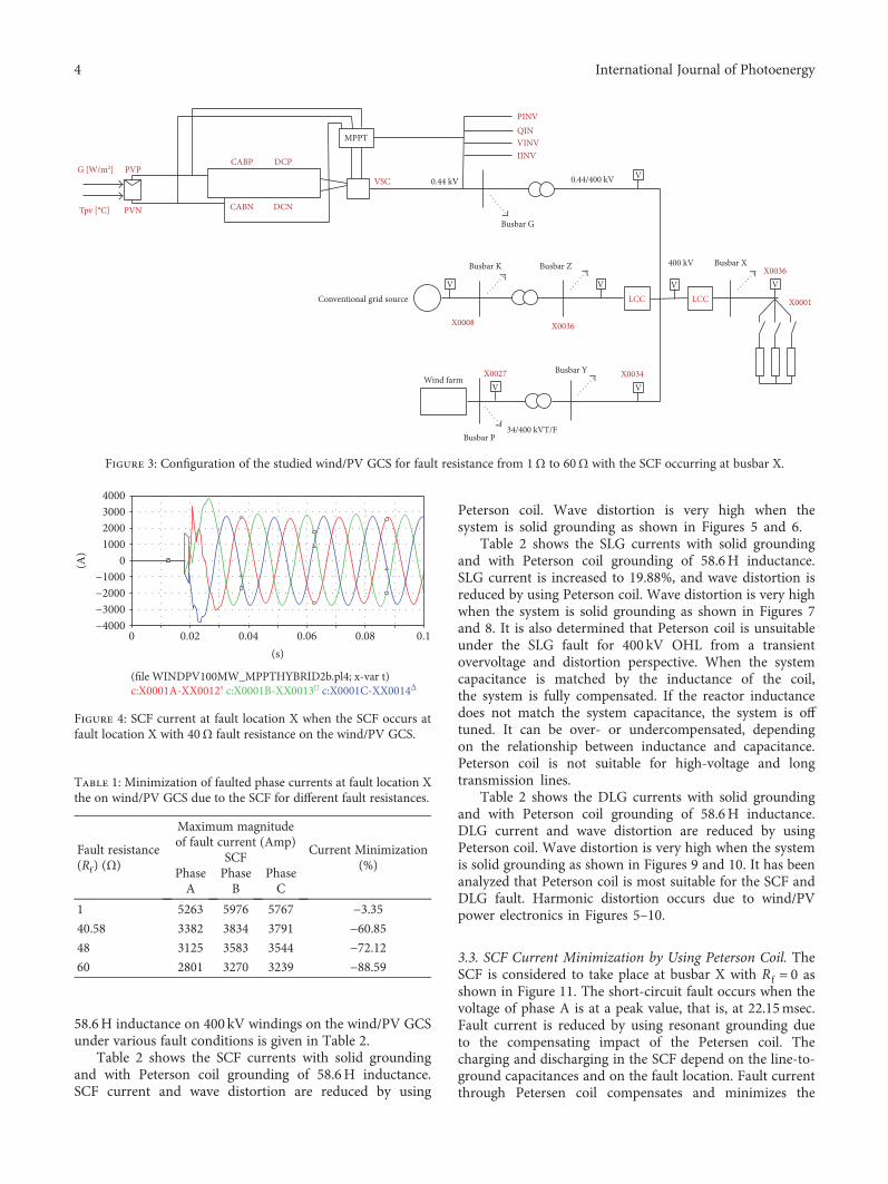
3.1. SCF Current Controlled by a Fault Resistor. The SCF isconsidered to take place at busbar X on the line as shownin Figure 3. The short-circuit fault occurs when the voltageof phase A is at a peak value, that is, at 22.15msec. Thewaveforms of the fault current at fault location X are givenin Figure 4. Minimization of faulted phase currents at faultlocation X on the wind/PV GCS due to the SCF for differentfault resistances is given in Table 1.
The maximum magnitude of fault currents at faultlocation X decreases as the fault resistance increases. Faultcurrent at fault location X decreases from 3.35% at 1Ω faultresistance to 88.59% at 60Ω fault resistances. It is alsoobserved that SCF current is reduced as fault resistance isincreased. Transients in the fault current waveform arehigher at a lower value of the fault resistance as comparedto a higher value expected. It is also analyzed that the waveattenuation is also higher due to the SCF as compared tothe LG fault.
3.2. Comparison between the Wind/PV GCS with SolidGrounding and That with Peterson Coil Grounding underVarious Faults. On this wind/PV GCS, different types offaults are considered such as the SLG fault, DLG fault, andSCF. The LG fault occurs on phase A at the end OHL, thatis, 400 kV. In the case of the DLG fault, the fault occurs atthe receiving end of the line on phases A and B. A compari-son between solid grounding and Peterson coil grounding of
LCC LCCV
Busbar G
Busbar K Busbar Z 400 kV Busbar X
X0007 X0033
X0035
Conventional grid
Busbar YWind farm
34/400 kVBusbar P
X0031X0024
V V V
MPPT
CABN DCN
CABP DCPPVP
PVN
G [W/m2]
Tpv [°C]
V V
V0.44/400 kV
PINVQINVINVIINV
VSC 0.44 kVINVP
Figure 2: No-load wind/PV GCS.
3International Journal of Photoenergy
58.6H inductance on 400 kV windings on the wind/PV GCSunder various fault conditions is given in Table 2.
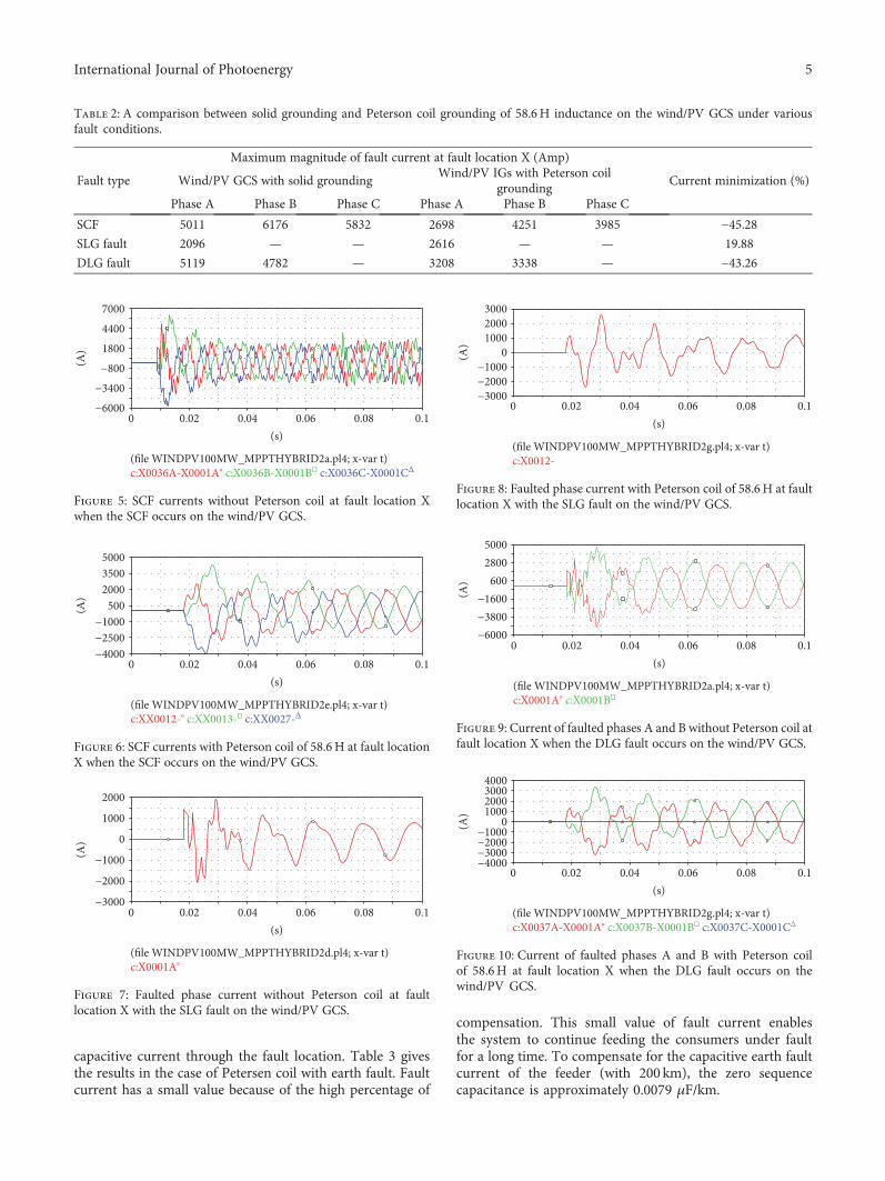
Table 2 shows the SCF currents with solid groundingand with Peterson coil grounding of 58.6H inductance.SCF current and wave distortion are reduced by using
Peterson coil. Wave distortion is very high when thesystem is solid grounding as shown in Figures 5 and 6.
Table 2 shows the SLG currents with solid groundingand with Peterson coil grounding of 58.6H inductance.SLG current is increased to 19.88%, and wave distortion isreduced by using Peterson coil. Wave distortion is very highwhen the system is solid grounding as shown in Figures 7and 8. It is also determined that Peterson coil is unsuitableunder the SLG fault for 400 kV OHL from a transientovervoltage and distortion perspective. When the systemcapacitance is matched by the inductance of the coil,the system is fully compensated. If the reactor inductancedoes not match the system capacitance, the system is offtuned. It can be over- or undercompensated, dependingon the relationship between inductance and capacitance.Peterson coil is not suitable for high-voltage and longtransmission lines.
Table 2 shows the DLG currents with solid groundingand with Peterson coil grounding of 58.6H inductance.DLG current and wave distortion are reduced by usingPeterson coil. Wave distortion is very high when the systemis solid grounding as shown in Figures 9 and 10. It has beenanalyzed that Peterson coil is most suitable for the SCF andDLG fault. Harmonic distortion occurs due to wind/PVpower electronics in Figures 5–10.
3.3. SCF Current Minimization by Using Peterson Coil. TheSCF is considered to take place at busbar X with Rf = 0 asshown in Figure 11. The short-circuit fault occurs when thevoltage of phase A is at a peak value, that is, at 22.15msec.Fault current is reduced by using resonant grounding dueto the compensating impact of the Petersen coil. Thecharging and discharging in the SCF depend on the line-to-ground capacitances and on the fault location. Fault currentthrough Petersen coil compensates and minimizes the
LCC LCCV
Busbar G
Busbar K Busbar Z 400 kV Busbar X
X0008 X0036
X0036
Conventional grid source
Busbar YWind farm
34/400 kVT/FBusbar P
X0034X0027
V V V
MPPT
CABN DCN
CABP DCPPVP
PVN
G [W/m2]
Tpv [°C]
V V
V0.44/400 kV
PINVQINVINVIINV
VSC 0.44 kV
X0001
Figure 3: Configuration of the studied wind/PV GCS for fault resistance from 1Ω to 60Ω with the SCF occurring at busbar X.
0.040.02 0.06 0.08 0.1(s)
−2000
−4000−3000
3000
0
(A)
2000
4000
10000
−1000
(�le WINDPV100MW_MPPTHYBRID2b.pl4; x‐var t)c:X0001A‐XX0012∘ c:X0001B‐XX0013�㐀 c:X0001C‐XX0014Δ
Figure 4: SCF current at fault location X when the SCF occurs atfault location X with 40Ω fault resistance on the wind/PV GCS.
Table 1: Minimization of faulted phase currents at fault location Xthe on wind/PV GCS due to the SCF for different fault resistances.
Fault resistance(Rf) (Ω)
Maximum magnitudeof fault current (Amp)
Current Minimization(%)
SCFPhaseA
PhaseB
PhaseC
1 5263 5976 5767 −3.3540.58 3382 3834 3791 −60.8548 3125 3583 3544 −72.1260 2801 3270 3239 −88.59
4 International Journal of Photoenergy
capacitive current through the fault location. Table 3 givesthe results in the case of Petersen coil with earth fault. Faultcurrent has a small value because of the high percentage of
compensation. This small value of fault current enablesthe system to continue feeding the consumers under faultfor a long time. To compensate for the capacitive earth faultcurrent of the feeder (with 200 km), the zero sequencecapacitance is approximately 0.0079 μF/km.
Table 2: A comparison between solid grounding and Peterson coil grounding of 58.6H inductance on the wind/PV GCS under variousfault conditions.
Fault type
Maximum magnitude of fault current at fault location X (Amp)
Current minimization (%)Wind/PV GCS with solid groundingWind/PV IGs with Peterson coil
groundingPhase A Phase B Phase C Phase A Phase B Phase C
SCF 5011 6176 5832 2698 4251 3985 −45.28SLG fault 2096 — — 2616 — — 19.88
DLG fault 5119 4782 — 3208 3338 — −43.26
0.040.02 0.06 0.08 0.1(s)
−800
−6000−3400
4400
0
(A) 1800
7000
(�le WINDPV100MW_MPPTHYBRID2a.pl4; x‐var t)c:X0036A‐X0001A∘ c:X0036B‐X0001B�㐀 c:X0036C‐X0001CΔ
Figure 5: SCF currents without Peterson coil at fault location Xwhen the SCF occurs on the wind/PV GCS.
0.040.02 0.06 0.08 0.1(s)
−1000
−4000−2500
3500
0
(A) 500
2000
5000
(�le WINDPV100MW_MPPTHYBRID2e.pl4; x‐var t)c:XX0012‐∘ c:XX0013‐�㐀 c:XX0027‐Δ
Figure 6: SCF currents with Peterson coil of 58.6H at fault locationX when the SCF occurs on the wind/PV GCS.
0.040.02 0.06 0.08 0.1(s)
−1000
−3000
−2000
2000
0
(A) 0
1000
(�le WINDPV100MW_MPPTHYBRID2d.pl4; x‐var t)c:X0001A∘
Figure 7: Faulted phase current without Peterson coil at faultlocation X with the SLG fault on the wind/PV GCS.
0.040.02 0.06 0.08 0.1(s)
−1000
−3000−2000
30002000
0
(A) 0
1000
(�le WINDPV100MW_MPPTHYBRID2g.pl4; x‐var t)c:X0012‐
Figure 8: Faulted phase current with Peterson coil of 58.6H at faultlocation X with the SLG fault on the wind/PV GCS.
0.040.02 0.06 0.08 0.1(s)
−1600
−6000−3800
600
50002800
0
(A)
(�le WINDPV100MW_MPPTHYBRID2a.pl4; x‐var t)c:X0001A∘ c:X0001B�㐀
Figure 9: Current of faulted phases A and B without Peterson coil atfault location X when the DLG fault occurs on the wind/PV GCS.
0.040.02 0.06 0.08 0.1(s)
0−1000−2000
−4000−3000
10002000
40003000
0
(A)
(�le WINDPV100MW_MPPTHYBRID2g.pl4; x‐var t)c:X0037A‐X0001A∘ c:X0037B‐X0001B�㐀 c:X0037C‐X0001CΔ
Figure 10: Current of faulted phases A and B with Peterson coilof 58.6H at fault location X when the DLG fault occurs on thewind/PV GCS.
5International Journal of Photoenergy
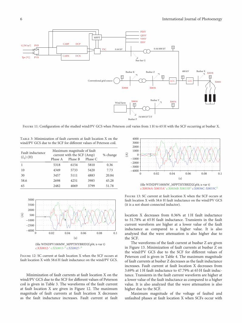
Minimization of fault currents at fault location X on thewind/PV GCS due to the SCF for different values of Petersoncoil is given in Table 3. The waveforms of the fault currentat fault location X are given in Figure 12. The maximummagnitude of fault currents at fault location X decreasesas the fault inductance increases. Fault current at fault
location X decreases from 0.36% at 1H fault inductanceto 51.78% at 65H fault inductance. Transients in the faultcurrent waveform are higher at a lower value of the faultinductance as compared to a higher value. It is alsoanalyzed that the wave attenuation is also higher due tothe SCF.
The waveforms of the fault current at busbar Z are givenin Figure 13. Minimization of fault currents at busbar Z onthe wind/PV GCS due to the SCF for different values ofPeterson coil is given in Table 4. The maximum magnitudeof fault currents at busbar Z decreases as the fault inductanceincreases. Fault current at fault location X decreases from3.69% at 1H fault inductance to 47.79% at 65H fault induc-tance. Transients in the fault current waveform are higher ata lower value of the fault inductance as compared to a highervalue. It is also analyzed that the wave attenuation is alsohigher due to the SCF.
Maximum magnitude of the voltage of faulted andunfaulted phases at fault location X when SCFs occur with
LCC LCCV
Bus‐bar G
Busbar K Busbar Z 400 kV Busbar X
X0008 X0036
X0038
Conventional grid source
Busbar YWind farm
34/400 kVT/FBusbar P
X0034X0026
V V V
MPPT
CABN DCN
CABP DCPPVP
PVN
G [W/m2]
Tpv [°C]
V V
V0.44/400 kV
PINVQINVVINVIINV
VSC 0.44 kV
X0001
Figure 11: Configuration of the studied wind/PV GCS when Peterson coil varies from 1H to 65H with the SCF occurring at busbar X.
Table 3: Minimization of fault currents at fault location X on thewind/PV GCS due to the SCF for different values of Peterson coil.
Fault inductance(Lf) (H)
Maximum magnitude of faultcurrent with the SCF (Amp) % change
Phase A Phase B Phase C
1 5318 6154 5810 0.36
10 4349 5733 5420 7.73
30 3457 5111 4883 20.84
58.6 2698 4251 3985 45.28
65 2482 4069 3799 51.78
0.040.02 0.06 0.08 0.1(s)
−1000−2500−4000
5002000
50003500
0
(A)
(�le WINDPV100MW_MPPTHYBRID2f.pl4; x‐var t)c:XX0012‐∘ c:XX0013‐�㐀 c:XX0027‐Δ
Figure 12: SC current at fault location X when the SCF occurs atfault location X with 58.6H fault inductance on the wind/PV GCS.
0.040.02 0.06 0.08 0.1(s)
0−1000−2000
−4000−3000
10002000
40003000
0
(A)
(�le WINDPV100MW_MPPTHYBRID2f.pl4; x‐var t)c:X0036A‐X0033A∘ c:X0036B‐X0033B�㐀 c:X0036C‐X0033CΔ
Figure 13: SC current at fault location X when the SCF occurs atfault location X with 58.6 H fault inductance on the wind/PV GCS(it is a not shunt-connected inductor).
6 International Journal of Photoenergy
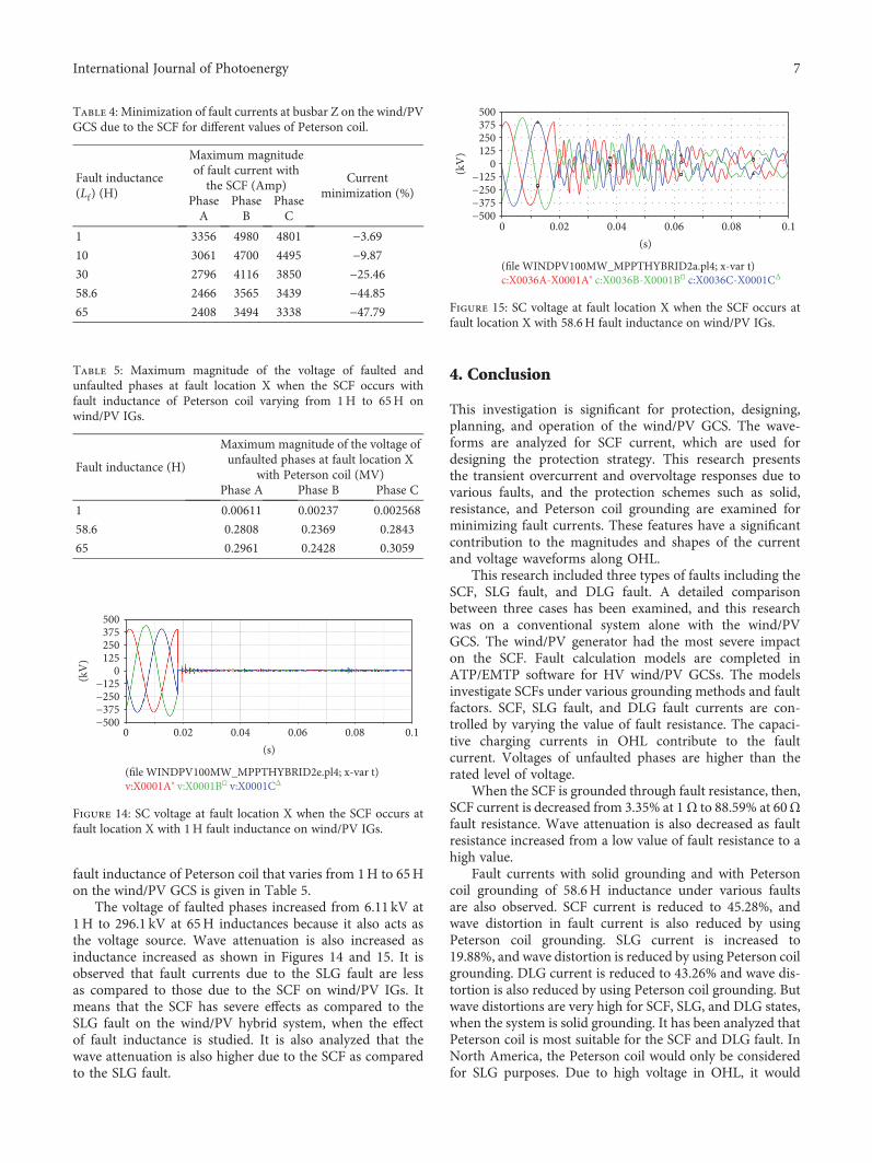
fault inductance of Peterson coil that varies from 1H to 65Hon the wind/PV GCS is given in Table 5.
The voltage of faulted phases increased from 6.11 kV at1H to 296.1 kV at 65H inductances because it also acts asthe voltage source. Wave attenuation is also increased asinductance increased as shown in Figures 14 and 15. It isobserved that fault currents due to the SLG fault are lessas compared to those due to the SCF on wind/PV IGs. Itmeans that the SCF has severe effects as compared to theSLG fault on the wind/PV hybrid system, when the effectof fault inductance is studied. It is also analyzed that thewave attenuation is also higher due to the SCF as comparedto the SLG fault.
4. Conclusion
This investigation is significant for protection, designing,planning, and operation of the wind/PV GCS. The wave-forms are analyzed for SCF current, which are used fordesigning the protection strategy. This research presentsthe transient overcurrent and overvoltage responses due tovarious faults, and the protection schemes such as solid,resistance, and Peterson coil grounding are examined forminimizing fault currents. These features have a significantcontribution to the magnitudes and shapes of the currentand voltage waveforms along OHL.
This research included three types of faults including theSCF, SLG fault, and DLG fault. A detailed comparisonbetween three cases has been examined, and this researchwas on a conventional system alone with the wind/PVGCS. The wind/PV generator had the most severe impacton the SCF. Fault calculation models are completed inATP/EMTP software for HV wind/PV GCSs. The modelsinvestigate SCFs under various grounding methods and faultfactors. SCF, SLG fault, and DLG fault currents are con-trolled by varying the value of fault resistance. The capaci-tive charging currents in OHL contribute to the faultcurrent. Voltages of unfaulted phases are higher than therated level of voltage.
When the SCF is grounded through fault resistance, then,SCF current is decreased from 3.35% at 1Ω to 88.59% at 60Ωfault resistance. Wave attenuation is also decreased as faultresistance increased from a low value of fault resistance to ahigh value.
Fault currents with solid grounding and with Petersoncoil grounding of 58.6H inductance under various faultsare also observed. SCF current is reduced to 45.28%, andwave distortion in fault current is also reduced by usingPeterson coil grounding. SLG current is increased to19.88%, and wave distortion is reduced by using Peterson coilgrounding. DLG current is reduced to 43.26% and wave dis-tortion is also reduced by using Peterson coil grounding. Butwave distortions are very high for SCF, SLG, and DLG states,when the system is solid grounding. It has been analyzed thatPeterson coil is most suitable for the SCF and DLG fault. InNorth America, the Peterson coil would only be consideredfor SLG purposes. Due to high voltage in OHL, it would
Table 5: Maximum magnitude of the voltage of faulted andunfaulted phases at fault location X when the SCF occurs withfault inductance of Peterson coil varying from 1H to 65H onwind/PV IGs.
Fault inductance (H)
Maximum magnitude of the voltage ofunfaulted phases at fault location X
with Peterson coil (MV)Phase A Phase B Phase C
1 0.00611 0.00237 0.002568
58.6 0.2808 0.2369 0.2843
65 0.2961 0.2428 0.3059
0.040.02 0.06 0.08 0.1(s)
0−125−250
−500−375
125250
500375
0
(kV
)
(�le WINDPV100MW_MPPTHYBRID2e.pl4; x‐var t)v:X0001A∘ v:X0001B�㐀 v:X0001CΔ
Figure 14: SC voltage at fault location X when the SCF occurs atfault location X with 1H fault inductance on wind/PV IGs.
0.040.02 0.06 0.08 0.1(s)
0
0−125−250
−500−375
125250
500375
(kV
)
(�le WINDPV100MW_MPPTHYBRID2a.pl4; x‐var t)c:X0036A‐X0001A∘ c:X0036B‐X0001B�㐀 c:X0036C‐X0001CΔ
Figure 15: SC voltage at fault location X when the SCF occurs atfault location X with 58.6H fault inductance on wind/PV IGs.
Table 4: Minimization of fault currents at busbar Z on the wind/PVGCS due to the SCF for different values of Peterson coil.
Fault inductance(Lf) (H)
Maximum magnitudeof fault current withthe SCF (Amp)
Currentminimization (%)
PhaseA
PhaseB
PhaseC
1 3356 4980 4801 −3.6910 3061 4700 4495 −9.8730 2796 4116 3850 −25.4658.6 2466 3565 3439 −44.8565 2408 3494 3338 −47.79
7International Journal of Photoenergy
require hundreds of higher voltage insulators over km; thus,it is never selected.
Minimization of fault currents at fault location X andbusbar Z on the wind/PV GCS due to the SCF for differentvalues of Peterson coil at fault location X is also examined.The maximum magnitude of fault currents at fault locationX decreases as the fault inductance increases. Fault currentat fault location X decreases from 0.36% at 1H fault induc-tance to 51.78% at 65H fault inductance. Transients in thefault current waveform are higher at a lower value of the faultinductance as compared to a higher value. The maximummagnitude of fault currents at busbar Z decreases as the faultinductance increases. Fault current at busbar Z decreasesfrom 3.69% at 1H fault inductance to 47.79% at 65H faultinductance. Transients in the fault current waveform arehigher at a lower value of the fault inductance as comparedto a higher value. It is also analyzed that the wave attenuationis also higher due to the SCF.
Conflicts of Interest
The authors declare that they have no conflicts of interest.
References
[1] J. M. Carrasco, L. G. Franquelo, J. T. Bialasiewicz et al.,“Power-electronic systems for the grid integration of renew-able energy sources: a survey,” IEEE Transactions on IndustrialElectronics, vol. 53, no. 4, pp. 1002–1016, 2006.
[2] R. Chedid and S. Rahman, “Unit sizing and control of hybridwind-solar power systems,” IEEE Transactions on EnergyConversion, vol. 12, no. 1, pp. 79–85, 1997.
[3] T. N. Boutsika and S. A. Papathanassiou, “Short-circuit calcu-lations in networks with distributed generation,” ElectricPower Systems Research, vol. 78, no. 7, pp. 1181–1191, 2008.
[4] H. R. Baghaee, M. Mirsalim, M. J. Sanjari, and G. B.Gharehpetian, “Effect of type and interconnection of DGunits in the fault current level of distribution networks,” in2008 13th International Power Electronics and Motion ControlConference, pp. 313–319, Poznan, Poland, September 2008.
[5] S. Boljevic andM. F. Conlon, “The contribution to distributionnetwork short-circuit current level from the connection ofdistributed generation,” in 2008 43rd International Universi-ties Power Engineering Conference, pp. 1–6, Padova, Italy,September 2008.
[6] S. Barghi, M. A. Golkar, and A. Hajizadeh, “Impacts of distri-bution network characteristics on penetration level of winddistributed generation and voltage stability,” in 2011 10thInternational Conference on Environment and ElectricalEngineering, pp. 1–4, Rome, Italy, May 2011.
[7] J. A. Martinez-Velasco, Transient Analysis of Power Systems:Solution Techniques, Tools and Applications, John Wiley &Sons Ltd., United Kingdom, 2014.
[8] L. van der Sluis, Transients in Power Systems, John Wiley &Sons Ltd., United Kingdom, 2001.
[9] M. Parkkonen, “The use of EMTPIATP program in inductiongenerator connection studies to the electrical network,” inMinutes of the 23rd EMTP User Group Meeting, Lisbon,Portugal, June 1993.
[10] IEEE, STANDARD 142-2007-IEEE Recommended Practice forGrounding of Industrial and Commercial Power Systems(Green Book), IEEE, USA, 2007.
[11] IEEE, STANDARD 1100-2005-IEEE Recommended Practice forPowering and Grounding Electronic Equipment (EmeraldBook), IEEE, USA, 2006.
[12] D. D. Shipp and F. J. Angelini, “Characteristics of differentpower systems neutral grounding techniques: fact and fiction,”in IEEE Textile, Fiber and Film Industry Technical Conference1991, Greenville, SC, USA, May 1991.
[13] A. R. Al-Zyoud, A. Alwadie, A. Elmitwally, and A. Basheer,“Effect of neutral grounding methods on the earth fault char-acteristics,” in PIERS Proceedings, pp. 1144–1151, Prague,Czech Republic, July 2015.
[14] M. Pühringer, Resonant Grounding as Approach to SystemNeutral Grounding, Haefely Trench, Austria, 1998.
[15] D. Jacob and K. Nithiyanthan, “Effective methods for powersystems grounding,” WSEAS Transactions on Business andEconomics, vol. 5, no. 5, pp. 151–160, 2008.
[16] P. Pillai, A. Pierce, B. Bailey et al., “Grounding and groundfault protection of multiple generator installations onmedium-voltage industrial and commercial systems, part 2:grounding methods,” in Conference Record of the 2002 IEEEIndustry Applications Conference. 37th IAS Annual Meeting(Cat. No.02CH37344), vol. 3, pp. 1888–1895, Pittsburgh, PA,USA, October 2002.
[17] A. Bapat, R. Hanna, and S. Panetta, “Advanced concepts inhigh resistance grounding,” in Petroleum and Chemical Indus-try Technical Conference (PCIC), 2012 Record of ConferencePapers Industry Applications Society 59th Annual IEEE,pp. 1–9, Chicago, IL, USA, September 2012.
[18] M. T. Al-Hajri, “Neutral ground resistor monitoringschemes,” in 2004 Conference Record of the IEEE Interna-tional Symposium on Electrical Insulation, Indianapolis IN,USA, September 2004.
[19] J. Roberts, H. J. Altuve, and D. Hou, Review of GroundFault Protection Methods for Grounded, Ungrounded, andCompensated Distribution Systems, Schweitzer EngineeringLaboratories, Inc., Pullman, WA USA, 2001.
[20] T. Welfonder and V. Leitloff, “Location strategies and evalua-tion of detection algorithms for earth faults in compensatedMV distribution systems,” IEEE Transactions on PowerDelivery, vol. 15, no. 4, pp. 1121–1128, 2000.
[21] D. Griffel, Y. Harmand, V. Leitloff, and J. Bergeal, “A new dealfor safety and quality on MV networks,” IEEE Transactions onPower Delivery, vol. 12, no. 4, pp. 1428–1433, 1997.
[22] M. Abdel-Fattah, “A transient fault detection technique withvarying fault detection window of earth modes in unearthedMV systems,” in 2008 Power Quality and Supply ReliabilityConference, Parnu, Estonia, August 2008.
[23] L. F. Hunt and J. H. Vivian, “Sensitive ground protection forradial distribution feeders,” Transactions of the AmericanInstitute of Electrical Engineers, vol. 59, pp. 84–90, 1940.
[24] I. Zamora, A. J. Mazon, F. Antepara, M. Puhringer, andJ. R. Saenz, “Experiences of neutral resonant system imple-mentation in Gorliz substation,” in CI RED 17th Interna-tional Conference on Electricity Distribution, Barcelona,May 2003.
[25] R. Van de Sandt, J. Lowen, J. Paetzold, and I. Erlich, “Neutralearthing in off-shore wind farm grids,” in 2009 IEEE BucharestPowerTech, Bucharest, Romania, June–July 2009.
8 International Journal of Photoenergy
[26] S. H. Dumitru Toader, C. Blaj, and I. Cata, NumericalSimulation of Single Phase Faults in Medium Voltage ElectricalNetworks, University of Timisoara, Romania, 2010.
[27] A. K. Gernot Druml and O. Seifert, “A new directionaltransient relay for high ohmic earth faults,” in CI RED17th International Conference on Electricity Distribution,Barcelona, Spain, May 2003.
[28] T. Henriksen and A. Petteteig, “Detection of earth fault in amedium voltage distribution network,” in International Con-ference on Power System Transients, Lyon, France, June 2007.
[29] A. Cerretti, F. M. Gatta, A. Geri, S. Lauria, M. Maccioni, andG. Valtorta, “Temporary overvoltages due to ground faults inMV networks,” in 2009 IEEE Bucharest PowerTech, Bucharest,Romania, June–July 2009.
[30] A. B. S. Mariappan, M. Rayees, and M. AlDahmi, “Earthingsystem analysis to improve protection system performance indistribution networks,” in 12th IET International Conferenceon Developments in Power System Protection (DPSP 2014),pp. 1–6, Copenhagen, Denmark, March–April 2014.
[31] P. Toman, J. Dvorak, J. Orsagova, and S. Misak, “Experimentalanalysis of electrical values during earth faults,” in Proceedingsof the 2010 Electric Power Quality and Supply ReliabilityConference, pp. 185–190, Kuressaare, Estonia, June 2010.
[32] M. Lehtoneen, “Characteristics of earth faults in electricaldistribution networks with high impedance earthing,” ElectricPower Systems Research, vol. 44, no. 3, pp. 155–161, 1998.
[33] IEEE, C37.101-1993-IEEE Guide for Generator Ground Protec-tion, IEEE, USA, 1994.
[34] B. A. Mork, F. Gonzalez, D. Ishchenko, D. L. Stuehm, andJ. Mitra, “Hybrid transformer model for transient simulation-part I: development and parameters,” IEEE Transactions onPower Delivery, vol. 22, pp. 248–255, 2007.
[35] F. Umer, N. Cetinkaya, and G. S. Shehu, “Transient analysis ofshort circuit faults in PV hybrid systems,” in EEETEM IEEEConference, pp. 28–35, Beirut, Lebanon, April 2017.
9International Journal of Photoenergy

Submit your manuscripts athttps://www.hindawi.com
Hindawi Publishing Corporationhttp://www.hindawi.com Volume 2014
Inorganic ChemistryInternational Journal of
Hindawi Publishing Corporation http://www.hindawi.com Volume 201
International Journal ofInternational Journal ofPhotoenergy
Hindawi Publishing Corporationhttp://www.hindawi.com Volume 2014
Carbohydrate Chemistry
International Journal ofInternational Journal of
Hindawi Publishing Corporationhttp://www.hindawi.com Volume 2014
Journal of
Chemistry
Hindawi Publishing Corporationhttp://www.hindawi.com Volume 2014
Advances in
Physical Chemistry
Hindawi Publishing Corporationhttp://www.hindawi.com
Analytical Methods in Chemistry
Journal of
Volume 2014
Bioinorganic Chemistry and ApplicationsHindawi Publishing Corporationhttp://www.hindawi.com Volume 2014
SpectroscopyInternational Journal of
Hindawi Publishing Corporationhttp://www.hindawi.com Volume 2014
The Scientific World JournalHindawi Publishing Corporation http://www.hindawi.com Volume 2014
Medicinal ChemistryInternational Journal of
Hindawi Publishing Corporationhttp://www.hindawi.com Volume 2014
Chromatography Research International
Hindawi Publishing Corporationhttp://www.hindawi.com Volume 2014
Applied ChemistryJournal of
Hindawi Publishing Corporationhttp://www.hindawi.com Volume 2014
Hindawi Publishing Corporationhttp://www.hindawi.com Volume 2014
Theoretical ChemistryJournal of
Hindawi Publishing Corporationhttp://www.hindawi.com Volume 2014
Journal of
Spectroscopy
Analytical ChemistryInternational Journal of
Hindawi Publishing Corporationhttp://www.hindawi.com Volume 2014
Journal of
Hindawi Publishing Corporationhttp://www.hindawi.com Volume 2014
Quantum Chemistry
Hindawi Publishing Corporationhttp://www.hindawi.com Volume 2014
Organic Chemistry International
ElectrochemistryInternational Journal of
Hindawi Publishing Corporation http://www.hindawi.com Volume 2014
Hindawi Publishing Corporationhttp://www.hindawi.com Volume 2014
CatalystsJournal of


![HighlyEfficientOrganicUVPhotodetectorsBasedon ...downloads.hindawi.com/journals/ijp/2012/936075.pdf · to 10− 2cm /Vs) [18, 19] and therefore find application in many different](https://img.pdfslide.us/doc/110x75/5e792269277d16014a5d3d49/highlyeficientorganicuvphotodetectorsbasedon-to-10a-2cm-vs-18-19-and.jpg)


![Development of a Daily Databank of Solar Radiation ...downloads.hindawi.com/journals/ijp/2019/6067539.pdfspatial variables [16] in different sky conditions [17, 18]. Also, this model](https://img.pdfslide.us/doc/110x75/5f4c69aa98954b29f8529b43/development-of-a-daily-databank-of-solar-radiation-spatial-variables-16-in.jpg)