Embed Size (px)
Citation preview
INTERNATIONAL JOURNAL OF MICROWAVE AND OPTICAL TECHNOLOGY,
Effectiveness of Linear FM Interference Signal on Tracking
Performance of PLL in Monopulse Radar Receivers
Harikrishna Paik*, Dr.N.N.Sastry, Dr.I.SantiPrabha
Assoc.Professor, Dept. of E&I Engg, VRSEC, Vijayawada, India
Professor & Dean, R&D Wing, VRSEC, Vijayawada, India
Professor, Dept. of ECE, JNT University, Kakinada, India
E-mail: [email protected], [email protected], [email protected]
Abstract—Monopulse radar receivers employing
phase locked loop (PLL) invariably track the
target in range and angle (frequency) domains. In
this paper, the tracking performance of PLL for a
highly application specific airborne tracking radar
in frequency domain is presented. Two different
signals such as the linear frequency modulated
(LFM) interference signal from a repeater source
and the radar echo signal are injected into the PLL
simultaneously with an assumption that initially,
the PLL locks onto the echo signal frequency. The
effectiveness of key parameters of LFM signal such
as frequency deviation, modulation rate and LFM
signal power on break-lock are demonstrated. The
simulation result shows that break-lock is achieved
at a frequency deviation of 0.36 MHz for a typical
LFM signal power of -14 dBm and 200 kHz
modulation rate when the radar echo power at the
PLL input is -14 dBm. The break-lock is studied
for a typical loop bandwidth of 200 kHz and
different values of radar echo signal power at the
PLL input. The computer simulation is carried out
using visual system simulator (VSS) AWR software
and potential conclusions are demonstrated.
Index Terms—frequency modulation, jamming,
monopulse, radar receiver, radar echo, tracking
I. INTRODUCTION
Several advanced techniques have been
employed in modern tracking radar against
electronic attack (EA) threat in electronic warfare scenario. These include pulse compression, Pulse
Doppler, Monopulse, Ultralow sidelobe antennas
and Coherent sidelobe cancellation etc. All these
techniques make modern radars difficult to jam and require special EA techniques for effective
jamming. Of these techniques, monopulse
technique is invariably used in all the tracking
radars and modern missile seekers [1]. However,
monopulse angle (frequency) tracking systems are difficult to jam because this technique
provides an inherent resistance to amplitude-
modulated jamming waveforms from point target
sources [2]. Several jamming techniques have been employed against monopulse tracking
systems which include noise jamming, deception
jamming, transponder jamming and support jamming. In these techniques, the radar receiver
is jammed either by introducing imperfections in
the monopulse design or by using multiple repeater sources in order to distort the angle of
arrival of the echo signal. Thus, the monopulse
tracker is caused to move away from the target
and results break-lock in the missile radar [3]. In this paper, the jamming of monopulse radar
receiver using deception jamming is illustrated.
The basic objective of the deception jamming scheme is to cause frequency (angular) break-
lock by injecting suitable modified replica of
radar echo signal into the tracking radar receiver.
The linear frequency modulated (LFM) signal from a repeater source is used as an interference
signal which is injected into the phase locked
loop (PLL) along with radar echo signal and break-lock in the PLL is analyzed.
The effects of LFM interference signal on
tracking performance of PLL in monopulse radar receiver have been presented in several studies
[4-7]. The statistical parameters of the monopulse
receiver such as steady state gain; tracking index
and range Doppler coupling coefficients in the presence of linear frequency modulation signal
have been derived in [4]. The time-frequency
characteristics of non-stationary LFM signal is estimated more precisely using Wigner Ville
VOL.10, NO.3, MAY 2015
202
IJMOT-2015-2-685 © 2015 IAMOT
INTERNATIONAL JOURNAL OF MICROWAVE AND OPTICAL TECHNOLOGY,
Transform to detect the presence of wrong
frequency component [5]. The maximum
likelihood angle estimation technique is analyzed [6-7] for the detection of two closely unresolved
targets in the sea clutter environment by
implementing modified generalized likelihood ratio. Here, we propose the generation of the
LFM signal by frequency modulating the
sinusoidal carrier by sawtooth waveform using a
frequency modulator. The PLL is assumed to be operating at an intermediate frequency (IF) of 50
MHz with a typical bandwidth of 200 kHz. The
radar echo and LFM jamming signal are applied to the PLL simultaneously. Initially, it is assumed
that the PLL locks onto the radar echo signal
frequency. The frequency deviation of LFM signal is increased such that the frequency
separation between these two signals increases.
Thus, the PLL loses the frequency lock from the
echo signal and locks on to the jamming signal frequency. The frequency deviation required for
break-lock is estimated as a function of LFM
jammer power for different modulation rates such as 200, 300, 400 kHz, and so. The break-lock is
studied for different values of jammer signal
power in the range between -14 and -2 dBm and the echo signal powers of -14 and -10 dBm.
II. SYSTEM CONFIGURATION ANDMODELLING
A. Monopulse Radar Receiver
The basic block diagram of two channel
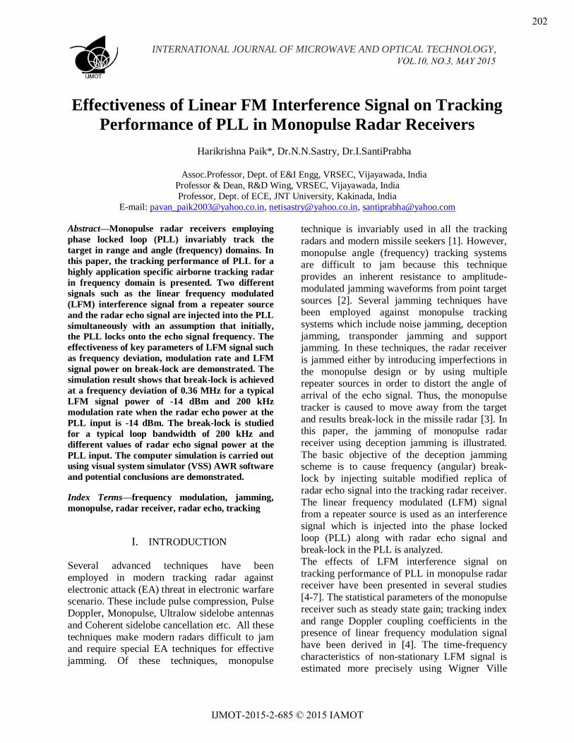
monopulse receiver is shown in Fig.1.
Fig.1. Block diagram of Monopulse Receiver
As shown in Fig. 1, the antenna feeds at the
receiver front end receive the echo signal
reflected from the target and the repeater interference signal. The outputs of antenna feeds
are then given to two inputs of hybrid junction,
which is a four port microwave device with two
input and two output ports. When the signals from two antenna feeds are applied at the input
ports, the sum and difference of the two are
obtained at the output ports. The resulting signals in each sum and difference channel are
heterodyned to an intermediate frequency (IF)
and then amplified by an IF amplifier as necessary. The amplitude of the difference signal
indicates the magnitude of the angular error, and
its phase indicates the direction of the off-axis
error. The sum channel signal is applied to the PLL to predict the break-lock behavior of the
receiver. The monopulse radar receiver
implemented using visual system simulation (VSS) AWR software is shown in Fig.2.
VOL.10, NO.3, MAY 2015
203
IJMOT-2015-2-685 © 2015 IAMOT
INTERNATIONAL JOURNAL OF MICROWAVE AND OPTICAL TECHNOLOGY,
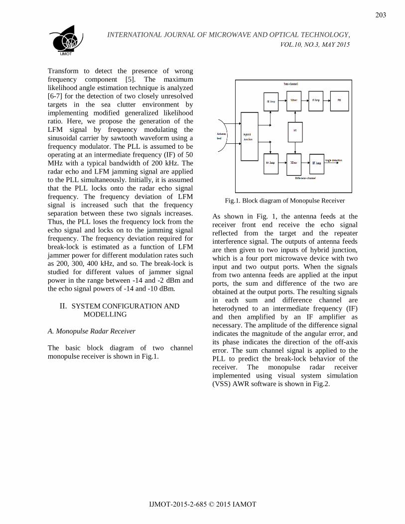
Fig.2. Monopulse receiver implemented using VSS
As shown in Fig.2, the sinusoidal CW radar echo
and the LFM interference signal are applied at
the receiver input simultaneously. The quadrature hybrid coupler at the receiver front end divides
the input signal into sum and difference channel
signals which are 900 out of phase to each other.
The signals in each channel are then amplified by
an RF amplifier and heterodyned to an IF
frequency centered at 50 MHz. The sum channel
signal is applied to the PLL and break-lock is predicted.
B. Phase locked loop
The monopulse radar receiver invariably employs
PLL as a frequency tracking subsystem. The PLL mainly includes a phase detector (PD), loop filter
and a voltage controlled oscillator (VCO). In a
classical PLL, when the reference signal and
repeat jamming signal are simultaneously applied at its input, the PLL acquires lock onto the
reference signal if the strength of the reference
signal is larger than the interference signal strength. When strength of interference signal
exceeds the echo signal strength, the PLL loses
the frequency lock from the reference signal and
locks onto certain other frequency [8]. Thus, break-lock is said to occur in the PLL. For our
simulation, the PLL with charge pump PD and a
third order passive loop filter is designed and
implemented VSS software. The charge pump
PD is chosen due to the fact that the charge pump
PD provides infinite pull-in range and zero steady state error [9]. Furthermore, a third order
filer is generally recommended for the most of
RF applications and it is rare that a PLL is constructed with a filter higher than third order.
In addition, the passive loop filter has the
advantage over active filter that there is no active
device to add noise into the PLL. The loop filter is designed using exact method. The exact
method of filter design involves with solving the
time constants and then determining the loop filter components from these time constants. The
different key parameters considered for design of
the loop filter are phase margin (), loop
bandwidth (fc), phase detector gain (K in mA), VCO gain (Kvco in MHz/volt) and pole ratio
(T31). The pole ratio is the ratio of third order pole and reference pole of the loop filter. The
phase margin determines the loop stability which
is typically chosen between 48 and 55 degree.
The loop bandwidth is the crucial parameter in filter design which determines the spur rejection
and lock time of the loop. The selection of pole
ratio has an impact on reference spur in the loop. The time constants of filter are determined from
phase margin () of the loop forward gain [G(s)] given by [10].
)311(tan 1)1(tan 1)2(tan 1TTTT
(1)
where, T1,T2 and T3 are the filter time constants.
The loop forward gain G(s) is given by:
)()( sZS
sGkk vco
(2)
where, Z(s) is loop impedance, K is phase detector gain, Kvco is gain of VCO. In equation
(1), the value of phase margin () and the pole ratio (T31) are known, so an equation containing
T1 and T2 can be obtained. Another equation of
T1 and T2 can be obtained by finding the maximum value of phase margin at a frequency
equal to the loop bandwidth. It is seen that the
loop maximizes the phase margin at a frequency equal to loop bandwidth [11]. So, we can write
VOL.10, NO.3, MAY 2015
204
IJMOT-2015-2-685 © 2015 IAMOT
INTERNATIONAL JOURNAL OF MICROWAVE AND OPTICAL TECHNOLOGY,
0
d
d
c
(3)
Solving the above equation, we can express
)3
(2
1
3
)1
(2
1
1
)2
(2
1
2
Tc
Tc
Tc
Tc
Tc
Tc
(4)
Now, solving equation (1) and (4) for two unknowns, the time constants T1 and T2 can be
determined. The time constant T3 can be obtained
by using the relation
TTT 3113 (5)
Once the time constants are determined, the loop
filter components are obtained by defining the
constants k1, k2, k3 and k4 given as:
c totk 1
(6)
kTTk 1)
31(
2 (7)
T
kTT
k
2
131
3
(8)
c
c
k
1
3
4 (9)
By solving the above four equations, the filter components R1, R2, C1, C2 and C3 are determined.
The typical parameters chosen for design of the
loop filter are: phase margin () = 55 deg., input frequency (fcomp) = 50MHz, loop bandwidth (fc) =
200 kHz, VCO output frequency (fout) = 4 GHz,
phase detector gain (K) = 2.5 mA and VCO gain
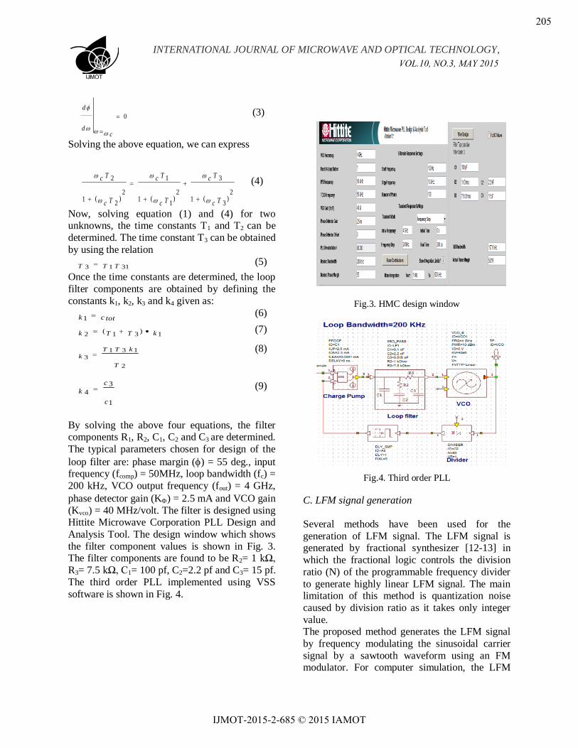
(Kvco) = 40 MHz/volt. The filter is designed using Hittite Microwave Corporation PLL Design and
Analysis Tool. The design window which shows
the filter component values is shown in Fig. 3. The filter components are found to be R2= 1 kΩ,
R3= 7.5 kΩ, C1= 100 pf, C2=2.2 pf and C3= 15 pf.
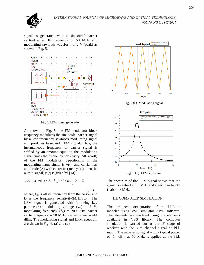
The third order PLL implemented using VSS
software is shown in Fig. 4.
Fig.3. HMC design window
Fig.4. Third order PLL
C. LFM signal generation
Several methods have been used for the
generation of LFM signal. The LFM signal is generated by fractional synthesizer [12-13] in
which the fractional logic controls the division
ratio (N) of the programmable frequency divider
to generate highly linear LFM signal. The main limitation of this method is quantization noise
caused by division ratio as it takes only integer
value. The proposed method generates the LFM signal
by frequency modulating the sinusoidal carrier
signal by a sawtooth waveform using an FM modulator. For computer simulation, the LFM
VOL.10, NO.3, MAY 2015
205
IJMOT-2015-2-685 © 2015 IAMOT
INTERNATIONAL JOURNAL OF MICROWAVE AND OPTICAL TECHNOLOGY,
signal is generated with a sinusoidal carrier
centred at an IF frequency of 50 MHz and
modulating sawtooth waveform of 2 V (peak) as shown in Fig. 5.
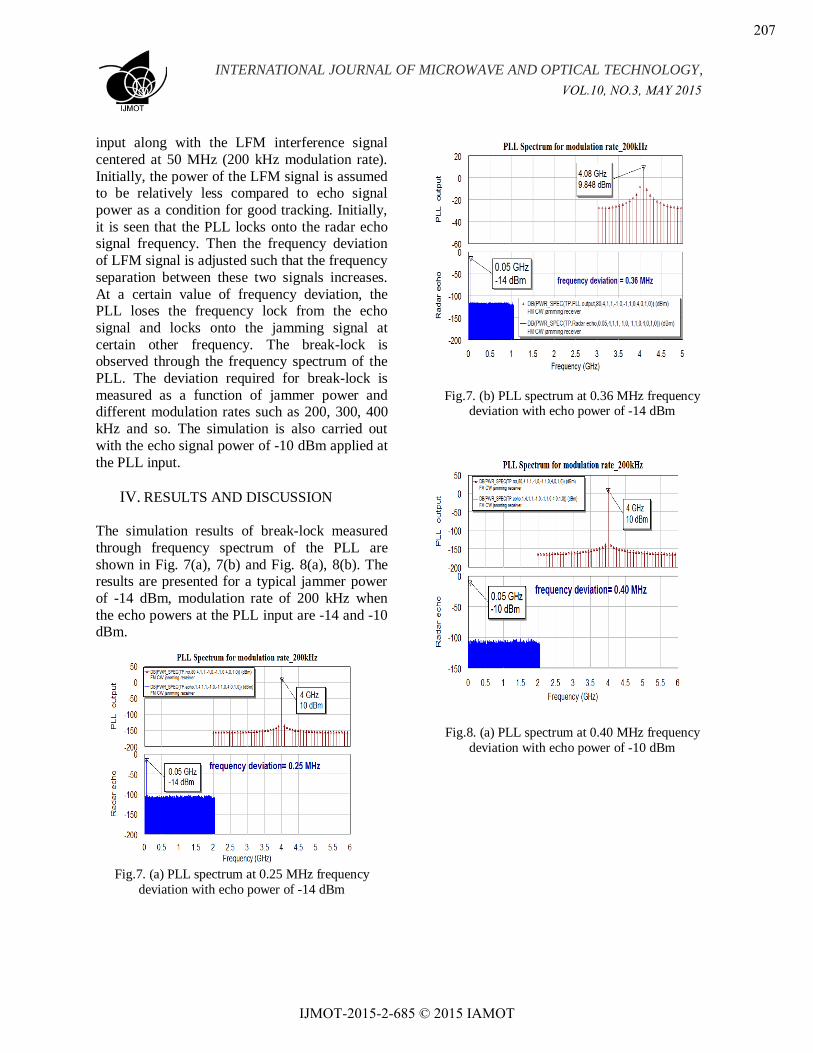
Fig.5. LFM signal generation
As shown in Fig. 5, the FM modulator block
frequency modulates the sinusoidal carrier signal by a low frequency sawtooth modulating signal
and produces baseband LFM signal. Thus, the
instantaneous frequency of carrier signal is shifted by an amount equal to the modulating
signal times the frequency sensitivity (MHz/volt)
of the FM modulator. Specifically, if the modulating input signal is v(t), and carrier has
amplitude (A) with center frequency (fc), then the
output signal, y (t) is given by [14]:
t
foff
dvtjty kfA0
)])(22(exp[)(
(10) where, foff is offset frequency from the carrier and
kf is the frequency sensitivity(MHz/volt). The
LFM signal is generated with following key parameters: modulating voltage (vm) = 2 V,
modulating frequency (fm) = 200 kHz, carrier
center frequency = 50 MHz, carrier power = -14
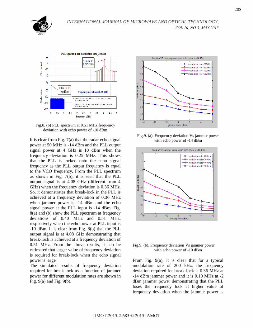
dBm. The modulating signal and LFM spectrum are shown in Fig. 6. (a) and (b).
Fig.6. (a). Modulating signal
Fig.6. (b). LFM spectrum
The spectrum of the LFM signal shows that the
signal is centred at 50 MHz and signal bandwidth
is about 5 MHz.
III. COMPUTER SIMULATION
The designed configuration of the PLL is modeled using VSS simulator AWR software.
The elements are modeled using the elements
available in VSS library. The computer simulation is carried out at the IF stage of
receiver with the sum channel signal at PLL
input. The radar echo signal with a typical power
of -14 dBm at 50 MHz is applied at the PLL
VOL.10, NO.3, MAY 2015
206
IJMOT-2015-2-685 © 2015 IAMOT
INTERNATIONAL JOURNAL OF MICROWAVE AND OPTICAL TECHNOLOGY,
input along with the LFM interference signal
centered at 50 MHz (200 kHz modulation rate).
Initially, the power of the LFM signal is assumed to be relatively less compared to echo signal
power as a condition for good tracking. Initially,
it is seen that the PLL locks onto the radar echo signal frequency. Then the frequency deviation
of LFM signal is adjusted such that the frequency
separation between these two signals increases.
At a certain value of frequency deviation, the PLL loses the frequency lock from the echo
signal and locks onto the jamming signal at
certain other frequency. The break-lock is observed through the frequency spectrum of the
PLL. The deviation required for break-lock is
measured as a function of jammer power and different modulation rates such as 200, 300, 400
kHz and so. The simulation is also carried out
with the echo signal power of -10 dBm applied at
the PLL input.
IV. RESULTS AND DISCUSSION
The simulation results of break-lock measured
through frequency spectrum of the PLL are
shown in Fig. 7(a), 7(b) and Fig. 8(a), 8(b). The results are presented for a typical jammer power
of -14 dBm, modulation rate of 200 kHz when
the echo powers at the PLL input are -14 and -10 dBm.
Fig.7. (a) PLL spectrum at 0.25 MHz frequency
deviation with echo power of -14 dBm
Fig.7. (b) PLL spectrum at 0.36 MHz frequency deviation with echo power of -14 dBm
Fig.8. (a) PLL spectrum at 0.40 MHz frequency
deviation with echo power of -10 dBm
VOL.10, NO.3, MAY 2015
207
IJMOT-2015-2-685 © 2015 IAMOT
INTERNATIONAL JOURNAL OF MICROWAVE AND OPTICAL TECHNOLOGY,
Fig.8. (b) PLL spectrum at 0.51 MHz frequency
deviation with echo power of -10 dBm
It is clear from Fig. 7(a) that the radar echo signal
power at 50 MHz is -14 dBm and the PLL output
signal power at 4 GHz is 10 dBm when the
frequency deviation is 0.25 MHz. This shows that the PLL is locked onto the echo signal
frequency as the PLL output frequency is equal
to the VCO frequency. From the PLL spectrum as shown in Fig. 7(b), it is seen that the PLL
output signal is at 4.08 GHz (different from 4
GHz) when the frequency deviation is 0.36 MHz. So, it demonstrates that break-lock in the PLL is
achieved at a frequency deviation of 0.36 MHz
when jammer power is -14 dBm and the echo
signal power at the PLL input is -14 dBm. Fig. 8(a) and (b) show the PLL spectrum at frequency
deviations of 0.40 MHz and 0.51 MHz,
respectively when the echo power at PLL input is -10 dBm. It is clear from Fig. 8(b) that the PLL
output signal is at 4.08 GHz demonstrating that
break-lock is achieved at a frequency deviation of
0.51 MHz. From the above results, it can be estimated that larger value of frequency deviation
is required for break-lock when the echo signal
power is large. The simulated results of frequency deviation
required for break-lock as a function of jammer
power for different modulation rates are shown in Fig. 9(a) and Fig. 9(b).
Fig.9. (a). Frequency deviation Vs jammer power
with echo power of -14 dBm
Fig.9. (b). Frequency deviation Vs jammer power
with echo power of -10 dBm
From Fig. 9(a), it is clear that for a typical modulation rate of 200 kHz, the frequency
deviation required for break-lock is 0.36 MHz at
-14 dBm jammer power and it is 0.19 MHz at -2 dBm jammer power demonstrating that the PLL
loses the frequency lock at higher value of
frequency deviation when the jammer power is
VOL.10, NO.3, MAY 2015
208
IJMOT-2015-2-685 © 2015 IAMOT
INTERNATIONAL JOURNAL OF MICROWAVE AND OPTICAL TECHNOLOGY,
less. Similarly, when the jammer is high, the
break-lock is achieved at lower value of
frequency deviation. It is also estimated that when the modulation rate of LFM signal is low,
break-lock is achieved at lower value of
frequency deviation. Similarly, larger value of deviation is required for break-lock when
modulation rate is high. From Fig. 9(a), it is seen
that the break-lock is achieved at 0.36 MHz when
modulation rate is 200 kHz and it is 0.91 MHz when modulation rate is 500 kHz. So, from the
above results it can be demonstrated that the
jammer power and frequency deviation are the key parameters for breaking the frequency lock in
the PLL. Thus, for effective jamming of the
monopulse receiver, the LFM jamming signal with suitable power and frequency deviation is to
be injected into the receiver along with the radar
echo signal.
V. CONCLUSIONS
The break-lock of phase locked loop in monopulse receiver in the presence of LFM
jamming signal has been presented. It is
demonstrated that the break-lock is achieved at a frequency deviation of 0.36 MHz for a typical
modulation rate of 200 kHz when both the echo
and LFM signal powers are -14 dBm. Furthermore, it is estimated that at jammer power
of -14 dBm, the frequency deviations required for
break-lock are 0.36 and 0.91 MHz when the
modulation rates of LFM signal are 200 and 500 kHz respectively. It is also verified that break-
lock is achieved at lower value of frequency
deviation when the modulation rate is less and at higher modulation rate, larger value of frequency
deviation is required for break-lock. So, from the
above simulation results, conclusions can be
drawn that for effective jamming of monopulse receiver using LFM jamming signal, the jammer
power and frequency deviation are to be selected
suitably. ACKNOWLEDGMENT
The authors would thanks to Siddhartha Academy of General & Technical Education who
provided the research facilities and technical
support. We are also indebted to Director and
Principal of the institute who extended support in
many useful technical discussions during the progress of this work.
REFERENCES
[1] D. C. Schleher, Introduction to Electronic
Warfare, 1st ed., Norwood, MA: Artech House, 1986.
[2] Samuel M Sherman, Monopulse Principles and Techniques, 2nd ed., Artech House, 1984.
[3] D. C. Schleher, Electronic Warfare in the Information Age, 2nd ed., Norwood, MA: Artech House, 1999.
[4] Winnie Wong, W. D. Blair, “Steady-State Tracking with LFM Waveforms,” IEEE
Transactions on Aerospace and Electronic Systems, Vol. 36, no. 2, pp. 701-709, April 2000.
[5] Christophe De Luigi, Eric Moreau, “An Iterative Algorithm for Estimation of Linear Frequency Modulated Signal Parameters,” IEEE Signal Processing Letters, Vol. 9, no. 4, pp. 127-129, April 2002.
[6] A. Sinha, T. Kirubarajan, Y. Bar-Shalom,
“Tracker and Signal Processing for the Benchmark Problem with Unresolved Targets,” IEEE Transactions on Aerospace and Electronic Systems, Vol. 42, no. 1 pp. 279-300, Jan. 2006.
[7] Blair W.D., Brandt-Pearce M., “Monopulse DOA Estimation of Two unresolved Rayleigh Targets,” IEEE Transactions on AES, Vol.37, no.2, pp. 452-469, April 2001.
[8] F M. Gardner, Phase lock Techniques, 2nd ed., John Wiley, 1979.
[9] Gardner F.M., Charge-Pump Phase-Lock Loops, IEEE Trans. Comm., Vol. COM-28, pp. 1849-1858, 1980.
[10] Keese, William O., An Analysis and Performance Evaluation of a Passive Filter Design Technique for Charge Pump Phased Locked Loops,
Application Note, National Semiconductor, 2001. [11] Franklin F., Powell D., and Emami-Naeini A.,
Feedback Control of Dynamic Systems, 3rd ed., Addison-Wesley, 1994.
[12] T. Musch and B.Schiek, “A highly linear frequency ramp generator based on a fractional divider phase locked loop,” IEEE Trans. Instrum. Meas., Vol. 48, pp. 634-637, April 1999.
[13] T. Musch, I. Rolfes and B. Schiek, “ Fractional divider concepts with phase locked control for the generation of precise linear frequency ramp,” in 28th EUMC Proc.., Amsterdam, Netherlands, pp. 451-456, Oct. 1998.
[14] S. Haykin, Communication Systems, 3rd ed., John Wiley & Sons, New York, 1994.
VOL.10, NO.3, MAY 2015
209
IJMOT-2015-2-685 © 2015 IAMOT