Embed Size (px)
Citation preview

Effectiveness ofBeaver Plastics’ INSULWORKS insulation
system used below radiant floor slabs
For:Beaver Plastics
Edmonton, Alberta, Canada
By:Dr John Straube and Chris Schumacher, B.Tech, B.A.Sc.
John Straube Building Envelope EngineeringWaterloo, Ontario, Canada
April 2000

Beaver Plastics INSULWORKS Effectiveness Page 1 of 10
Introduction
Beaver Plastics produces an expanded polystyrene (EPS) foam insulation board, namedINSULWORKS, for use below concrete slabs with radiant hydronic heating systems. The foamis preformed in such a way as to allow easy fixing of the hydronic tubing.
Beaver Plastics has noted market resistance to the use of insulation below concrete slabs becausethe existing research suggests that little or no insulation is required in this location for energysavings. However, there is no existing research into floor slabs that contain a heat source, suchas radiant floor heating. Also, in many cases slabs are placed over wet soils (i.e., highlyconductive) or even over high water tables (very high capacity heat sinks).
Despite the perceived benefits of underslab insulation in hydronic heating applications, thepotential benefits have not been studied or documented. Beaver Plastics requested that JohnStraube Building Envelope Engineering conduct a series of computer simulations to documentthe size of the energy savings from using below slab insulation in hydronically heated slabs.
Objectives and Scope
The objective of the proposed work is to estimate and demonstrate the magnitude of the energysavings from using insulation below concrete slabs on grade with radiant heating.
There are hundreds of possible combinations of insulation, soil type, and building configuration.To provide a reasonable scope, the number of situations has been restricted to the most practicaland likely combinations.
The study used the two-dimensional dynamic heat flow simulation software package Heat2D.This simulation program allows one to model the heat delivered to the slab by the individualradiant floor tubes. It also accounts for the ability of the soil and foundation materials to storeheat (termed thermal mass or heat capacity). Different floor finishes (e.g., carpet or woodflooring) can also be accurately modelled. These features of the dynamic simulation programallow for accurate and realistic results.
Program Outline
A series of simulations were conducted which modeled the two most commonfoundation/basement situations, a range of insulation values, and a range of soil properties.
Each model considered a house 8 meters wide and infinitely long. Narrower basements willhave slightly higher heat loss, and wider basements will have slightly less heat loss. Three-dimensional effects at corners also tend to increase heat loss somewhat. These additional lossescan be easily quantified but were not included in the limited scope of this work.
The two basement foundation systems considered are shown in Figure 1 as a function of thelocation of the heated slab. Additional important construction variables include the amount of

Beaver Plastics INSULWORKS Effectiveness Page 2 of 10
sub-slab insulation (either 2” of INSULWORKS or none) and the amount of insulation on thewall (2” of exterior EPS (R8) or R12 interior stud wall with batt insulation.
Typical finishes over radiantly heated concrete floor slabs range from ceramic tiles (practicallyno thermal resistance) to deep pile carpet (high thermal resistance). The more thermallyinsulating the floor finish, the higher temperature that the slab must be heated to deliversufficient heat into the house. The hotter the slab is operated, the more heat lost to the soil. Thethermal resistance of a ¾” wood floor (approximately RSI0.18) as the slab floor covering wasused for all simulations. Wood flooring is both a common finish over radiant slabs and itsthermal resistance falls in the middle of the range of values for finishes. An interior basementwall finish of ½” drywall was assumed for all basement cases.
2.1 m below grade At grade
Grade
Grade
4 m tocenter
4 m tocenter
Figure 1: Slab Locations Considered
Three different soil types have been considered and are listed in Table 1. The thermalconductivity and volumetric heat capacity for each type of soil has also been adjusted to accountfor the different densities and moisture contents.
Soil Description Conductivity(W/mK)
Heat Capacity(MJ/m3 K)
Dry Sandy Loam 0.70 1.50
Moist Clay 1.50 1.65
Wet Sand 2.30 1.80
Table 1: Soil Properties

Beaver Plastics INSULWORKS Effectiveness Page 3 of 10
The outdoor temperature has been assumed to vary in a manner representative of a moderatelycold climate. The peak summer temperature was fixed at 20 °C and the minimum winter averageat –10 °C. The monthly average temperatures of Toronto and Calgary have been plottedalongside the simulated climate in Figure 2. The interior temperature also was assumed to varysinusoidally, from a minimum of 20 °C on January 21st to a maximum of 24 °C on July 21st.Note that these values are averages for periods of about a week. Short-term variations will havelittle effect on the results since these variations are damped by the very high thermal storagecapacity of the soil.
-15
-10
-5
0
5
10
15
20
25
0 60 120 180 240 300 360
Days from June 21st
Te
mpe
ratu
re (
C)
Simulated Temperature
Toronto
Calgary
Figure 2: Interior and Exterior Temperature Conditions Assumed
It has been assumed that the slab will be heated from late October through to late March with aheat source strong enough to maintain a well-insulated house at proper temperatures. A peakheat flux of 40 W/m2 on January 21 was chosen, and the flux decreased sinusoidally (much likethe exterior temperature) during other times (Figure 3). The total annual amount of heat energydelivered to the house interior was maintained at about 130 kWh/m2. Houses with poorinsulation or excessive air leakage would require a higher heat flux and thus higher slabtemperature to maintain interior temperatures, and hence heat losses to the soil would also behigher.

Beaver Plastics INSULWORKS Effectiveness Page 4 of 10
0
10
20
30
40
50
0 60 120 180 240 300 360Days from June 21st
Hea
t F
lux
(W/m
2 )
Figure 3: Assumed Radiant Slab Heat Flux
The table below summarizes the range of variables considered in the research program. Thesevariables result in a total of 24 possible simulations.
Sub-slab Insulation None and 2” INSULWORKS
Slab location At Grade and 2.1 m below
Soil Conductivity, k 0.7, 1.5, 2.3 W/m•K
Foundation Wall Insulation 2” EPS exterior and interior RSI 2.1 batt
Table 2: Summary of Simulation Variables
As has been found by others, the heat flow situation below grade requires approximately 3 to 5years to stabilize from a uniform temperature start. Based on our preliminary simulation runs,the fifth heating season was chosen as the comparison period. All simulations began with auniform temperature of 5 °C on April 21st.
The simulation was conducted over a domain 20 m below grade, 0.3 m above grade and a total of24 m width. Because symmetry was assumed only half of the basement (e.g., from the center-line of the house) was modeled. Therefore the results are valid for an 8 m wide basement with20 m (24 m less the 4 m basement width) of soil on each side.

Beaver Plastics INSULWORKS Effectiveness Page 5 of 10
Results
Figures 4 through 7 provide snap shots of part of the result of the computer model (about 10 mwide and 6 m deep) at a specific time of the year, either Feb 21 or Aug 21. The black isothermlines provide a map of the temperatures, as do the colours (see the colour legend next to thefigures). The arrows show the direction and relative magnitude of the heat flow. The model isof exactly half of a basement, meaning that the mirror image could be attached to the right sideof the diagram to make a whole basement. The examples are all of a full basement situation, amoderately well insulated house, and a conductive soil type (i.e., wet sand). Hence, thesegraphical representations demonstrate the greatest heat loss of all the full basement simulationsconducted.
Figure 4 presents the temperatures and heat flux during August around a basement with 2” ofEPS foam below the slab. The warm air temperatures and warm house temperatures at this timeof year are heating the soil. Note that there is heat loss to the ground all year long (i.e. the soiltemperatures never reach the indoor air temperature).
Figure 4: Insulated Slab in August
Beaver Plastics INSULWORKS Effectiveness Page 6 of 10
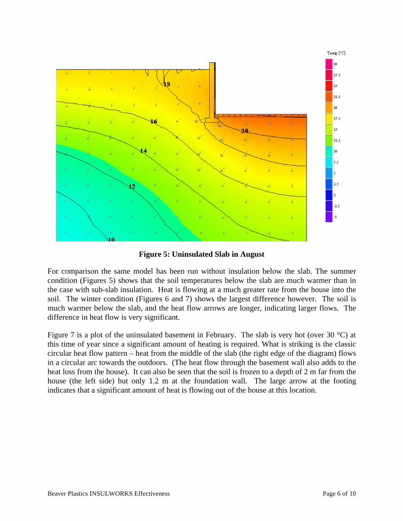
Figure 5: Uninsulated Slab in August
For comparison the same model has been run without insulation below the slab. The summercondition (Figures 5) shows that the soil temperatures below the slab are much warmer than inthe case with sub-slab insulation. Heat is flowing at a much greater rate from the house into thesoil. The winter condition (Figures 6 and 7) shows the largest difference however. The soil ismuch warmer below the slab, and the heat flow arrows are longer, indicating larger flows. Thedifference in heat flow is very significant.
Figure 7 is a plot of the uninsulated basement in February. The slab is very hot (over 30 °C) atthis time of year since a significant amount of heating is required. What is striking is the classiccircular heat flow pattern – heat from the middle of the slab (the right edge of the diagram) flowsin a circular arc towards the outdoors. (The heat flow through the basement wall also adds to theheat loss from the house). It can also be seen that the soil is frozen to a depth of 2 m far from thehouse (the left side) but only 1.2 m at the foundation wall. The large arrow at the footingindicates that a significant amount of heat is flowing out of the house at this location.

Beaver Plastics INSULWORKS Effectiveness Page 7 of 10
Figure 6: Insulated Slab in February
Figure 7: Uninsulated Slab in February

Beaver Plastics INSULWORKS Effectiveness Page 8 of 10
Figure 8 plots the average heat loss through the insulation into the soil over a typical year(centered about January, since this is the time when the slab is heated the most). The differencein heating energy that would have to be purchased for the case of 2” of EPS below the slab andthe case of the uninsulated slab is the difference between the two lines. The difference over theheating season is approximately 28 kWh/m2. Considering an energy cost of 10 cents per kWh,the annual cost savings would be about $2.80/m2/yr.
-3.0
-2.5
-2.0
-1.5
-1.0
-0.5
0.0180 240 300 360 420 480 540
Days From January 1st
Hea
t lo
ss (
kWh
/m2 w
eek)
Insulated, RSI1.41
Uninsulated
Figure 8: Heat Loss Compared for Insulated and Uninsulated Radiantly Heated BasementSlab (soil conductivity k=2.3 W/m•K)
The results in Figure 8 apply to a basement with the slab installed on moist, conductive soil.Table 3 and 4 summarize the results for 23 other combinations. In all cases, the use of insulationbelow the slab results in large reductions in heat flow. In fact, in the case of an uninsulatedheated slab, almost half of the purchased energy is lost to the soil. The more insulating the soil,the less the effect. The effect of a water table at a reasonable distance below the slab (not anunlikely scenario) would likely cause an even higher heat loss than shown for the high soilconductivity case.
Most existing recommendations for sub-slab insulation are based on unheated slabs. Twosimulations for an average soil case (i.e., moist clay soil, k=1.5, cp=1.65) were conducted. Theresults of these simulations are listed in Table 5. They show that the heat loss through both anuninsulated and insulated radiantly heated slab were over twice that of uninsulated and insulatedunheated slabs. Since heat loss through radiantly heated floors is so much higher than throughunheated slabs, the normal rules and practice for insulating unheated slabs clearly do not apply toradiantly heated slabs – more insulation is required for heated slabs.
Savings:
28.2 kWh/yr

Beaver Plastics INSULWORKS Effectiveness Page 9 of 10
Soil Properties Insulation Strategy Energy Use
ThermalConductivity, k
(W/mK)
Thermal HeatCapacity, cp
(kJ/kg K)
Wall(m2•K/W)
Slab(m2•K/W)
AnnualHeat Loss(kWh/m2)
AnnualSavings(kWh/m2)
2.3 1.8 1.41 1.41 -33.2 -28.2
2.3 1.8 1.41 0.00 -61.5
2.3 1.8 2.11 1.41 -35.9 -27.8
2.3 1.8 2.11 0.00 -63.7
1.5 1.65 1.41 1.41 -26.1 -16.6
1.5 1.65 1.41 0.00 -42.7
1.5 1.65 2.11 1.41 -28.9 -15.9
1.5 1.65 2.11 0.00 -44.8
0.7 1.5 1.41 1.41 -16.0 -6.8
0.7 1.5 1.41 0.00 -22.7
0.7 1.5 2.11 1.41 -18.3 -6.8
0.7 1.5 2.11 0.00 -25.1
Table 3: Full Basement Heat Loss Simulation Results
Soil Properties Insulation Strategy Energy Use
ThermalConductivity, k
(W/mK)
Thermal HeatCapacity, cp
(kJ/kg K)
Wall(m2•K/W)
Slab(m2•K/W)
AnnualHeat Loss(kWh/m2)
AnnualSavings(kWh/m2)
2.3 1.8 1.41 1.41 -38.1 -31.2
2.3 1.8 1.41 0.00 -69.3
2.3 1.8 0.70 1.41 -39.8 -34.6
2.3 1.8 0.70 0.00 -74.4
1.5 1.65 1.41 1.41 -30.9 -18.6
1.5 1.65 1.41 0.00 -49.5
1.5 1.65 0.70 1.41 -32.6 -20.7
1.5 1.65 0.70 0.00 -53.3
0.7 1.5 1.41 1.41 -20.1 -7.0
0.7 1.5 1.41 0.00 -27.0
0.7 1.5 0.70 1.41 -21.4 -8.1
0.7 1.5 0.70 0.00 -29.5
Table 4: Slab at Grade Heat Loss Simulation Results
Soil Properties Insulation Strategy Energy Use
ThermalConductivity, k
(W/mK)
Thermal HeatCapacity, cp
(kJ/kg K)
Wall(m2•K/W)
Slab(m2•K/W)
AnnualHeat Loss(kWh/m2)
Percentage ofRadiantly
Heated Slab1.5 1.65 1.41 1.41 -13.8 45%1.5 1.65 1.41 0.00 -20.8 42%
Table 5: Full Basement Heat Loss Simulation Results for Unheated Slabs

Beaver Plastics INSULWORKS Effectiveness Page 10 of 10
Another issue is the importance of slab edge insulation for local heat loss. As we have found inother studies, a piece of 4” high and ¾” thick EPS between the slab and the wall is likely themost cost effective piece of insulation in the entire house. If possible, this insulation between theheated slab and the unheated wall should be at least 1” thick.
Conclusions
Detailed two-dimensional dynamic computer simulations of radiantly-heated slabs has shownthat under-slab insulation can significantly reduce heat loss. The size of the energy savings willdepend on many variables such as climate, house design, and soil properties. Only the effect ofsoil properties was investigated in this study, and found to be significant in the cold climateconditions simulated.
Heat loss for a slab on grade averaged only about 15% greater than heat loss through a slab in afull basement. Placing the slab about 2 m (6 feet) lower in the ground therefore does not reduceenergy loss to any great extent. It can be concluded that the additional 2 m (6 feet) of soil is notan effective insulator.
It was found that the heat loss through an uninsulated radiantly heated slab can be reduced by asmuch as 46% if insulated with 50 mm (2" or R8) of EPS. Therefore, 75 mm (3" or R12) couldbe expected to reduce sub-slab heat loss by more than 50% in many situations.
Heat losses through radiantly heated slabs were found to be over twice that of otherwise similarunheated slabs for the conditions considered. Since heat loss through radiantly heated floors canbe so much higher than heat losses through unheated slabs, it can be concluded that the normalrules and practices for insulating unheated slabs clearly do not apply to radiantly heated slabs.
Sincerely,
John Straube, Ph.D. Chris Schumacher, B.Tech (Arch), B.A.Sc.
JS/js


![BEAVER PAGE - furharvesters.com · beaver page - 3-----|-----|----- con't eastern [ 18.00] | |](https://img.pdfslide.us/doc/110x75/5c12044b09d3f2602c8cd5df/beaver-page-beaver-page-3-cont-eastern-1800-.jpg)